Huace Navigation Technology A020012 GNSS Infrastructure User Manual
Shanghai Huace Navigation Technology LTD. GNSS Infrastructure
UserManual.wiki
>
Huace Navigation Technology
>
A020012 User Manual
User Manual
Navigation menu
Upload a User Manual
Namespaces
Wiki Guide
HTML
PDF
Info
Views
User Manual
Discussion / Help
Navigation
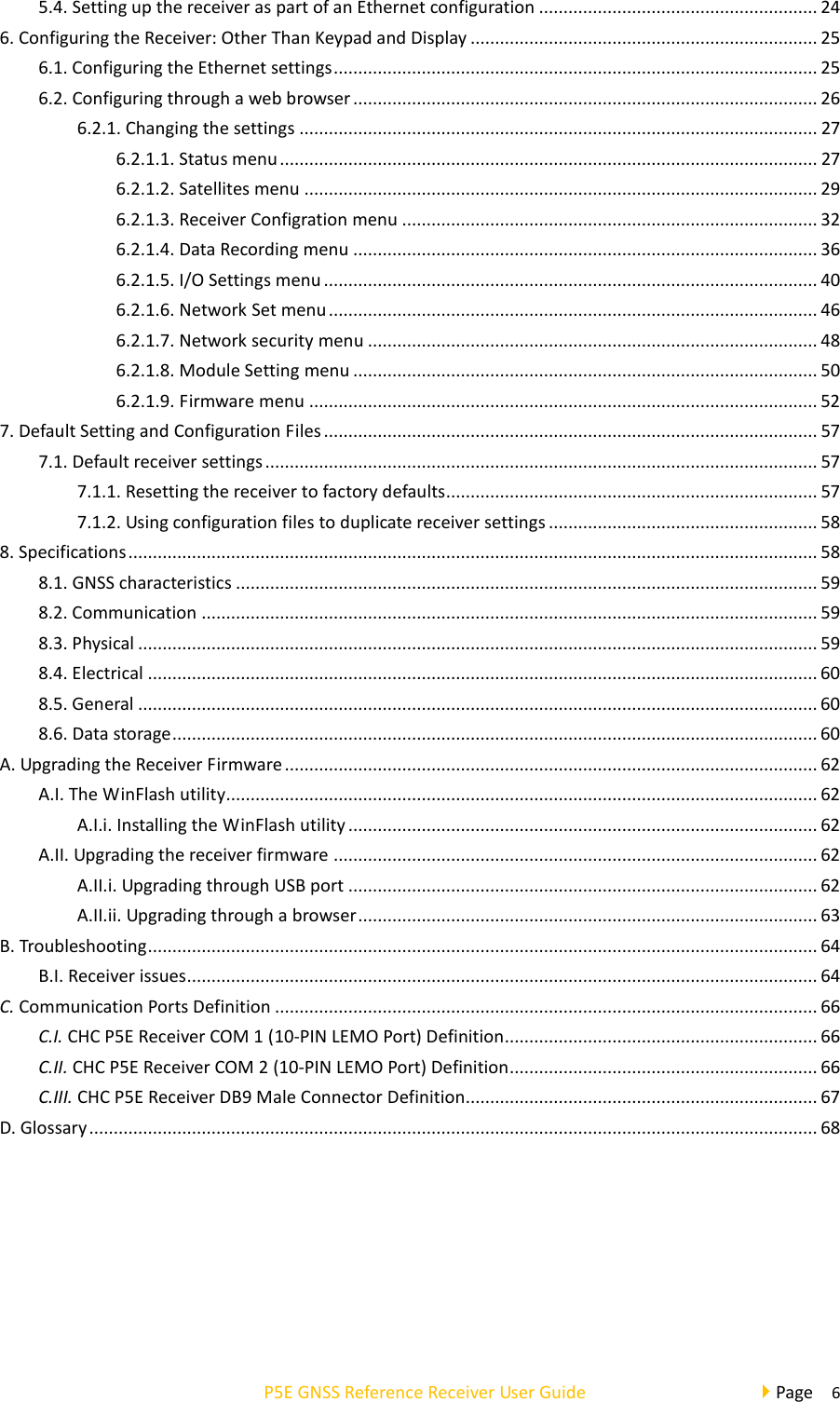

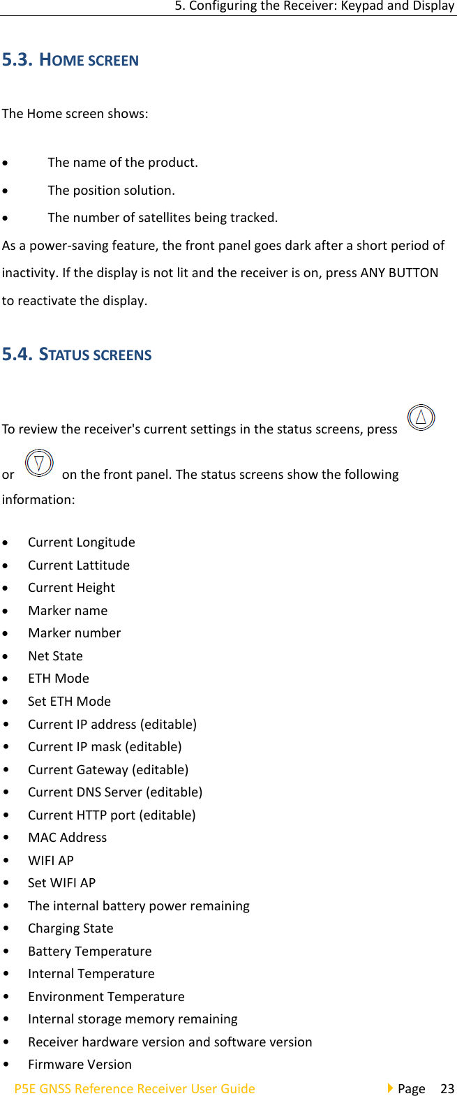
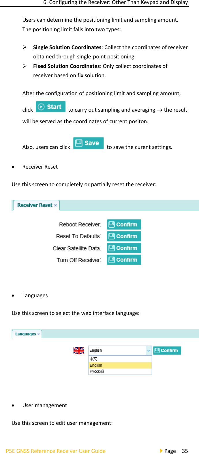
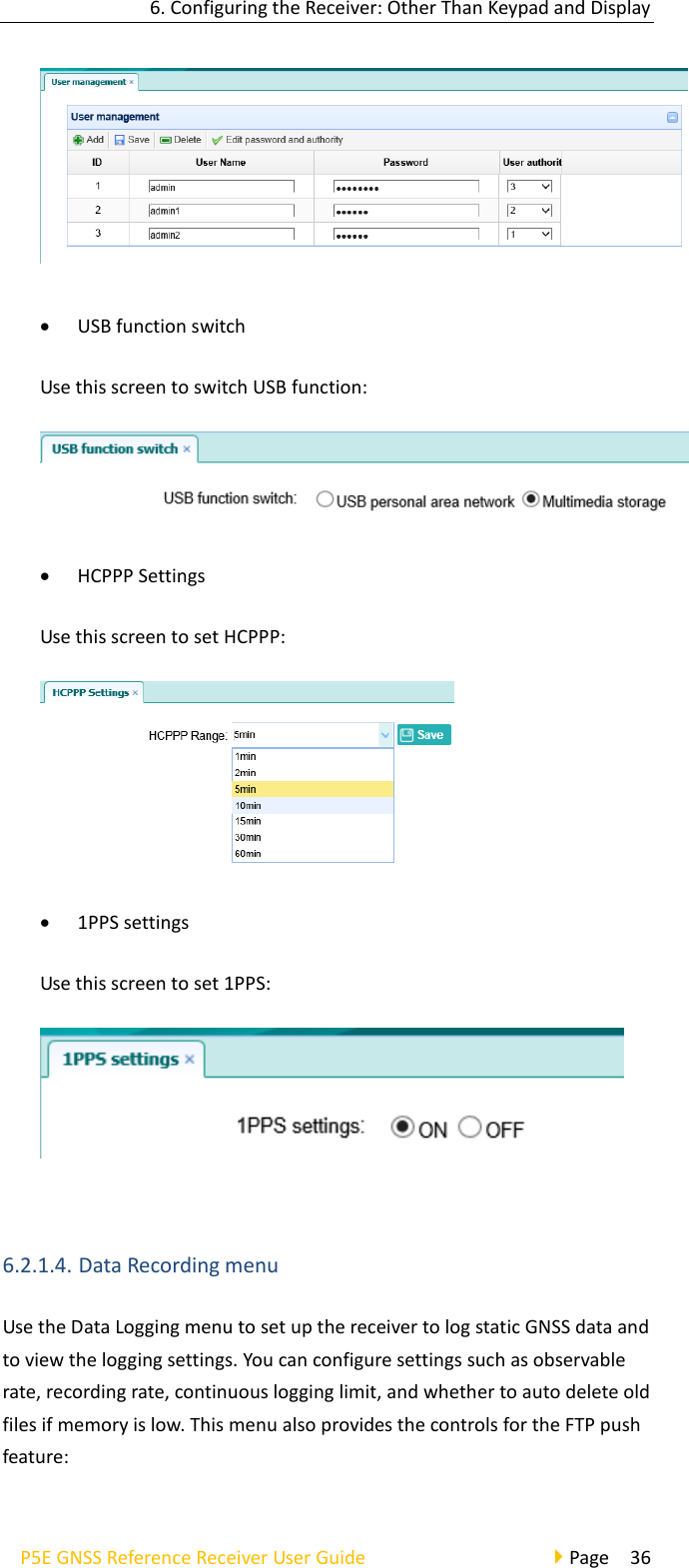
![6. Configuring the Receiver: Other Than Keypad and Display P5E GNSS Reference Receiver User Guide Page 37 • Log Settings Shows the data logging status, internal and external storage usage and data logging status of each storage thread. Also, users can configure the data logging settings for each storage thread, including recording name, saving location, storage limit, store formats, start time, etc. To open or close all the storage threads, click the [ON] or [OFF] button to the right of Log Status field. NOTE – The [ON] and [OFF] button to the right of Log Status field are the Master Log Switch. Every storage thread can log data only when the Master Log Switch is ON. And users can edit the settings of storage threads only when the Master Log Switch is OFF. To edit the settings of each storage thread, click the [Modify] button to the right of the required storage thread, and then the Recording Edit screen appears:](https://usermanual.wiki/Huace-Navigation-Technology/A020012/User-Guide-3907363-Page-38.png)
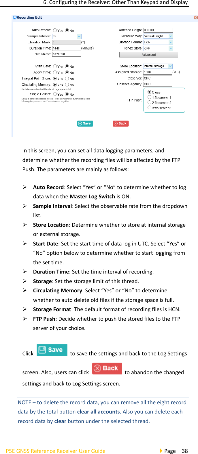
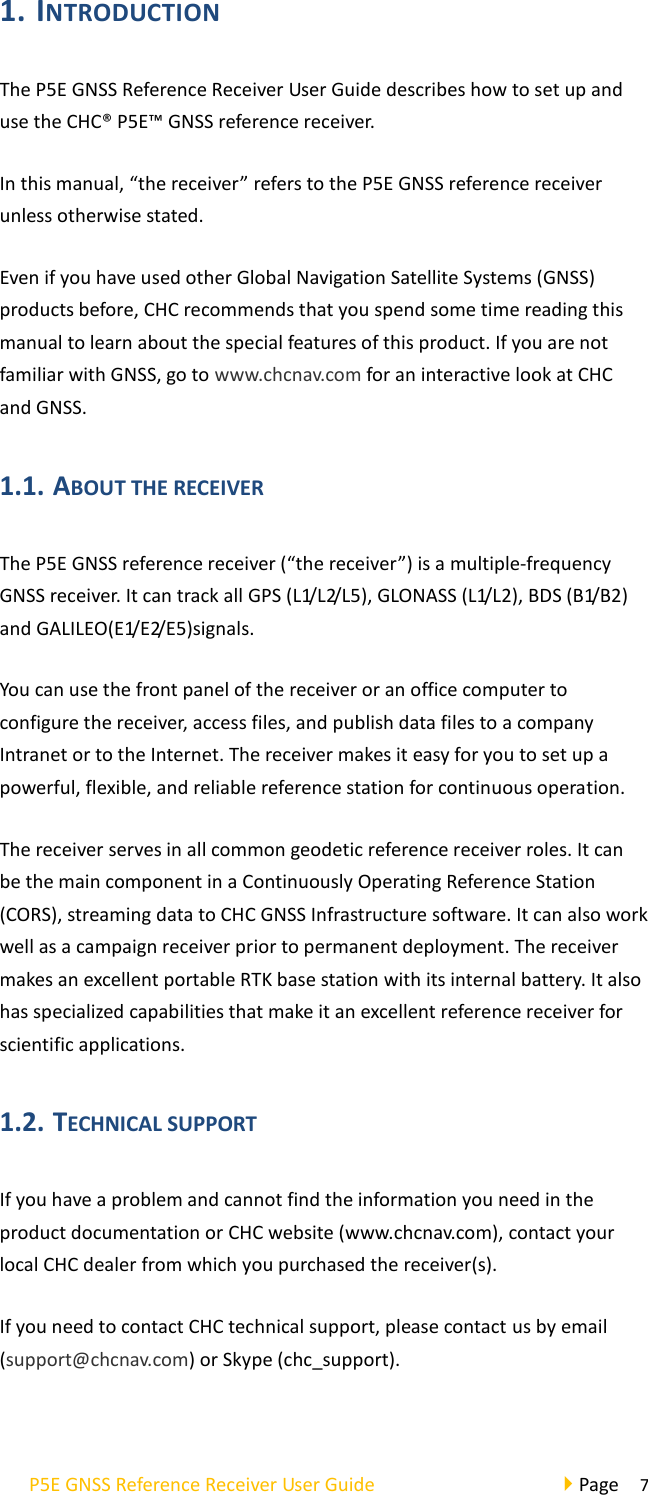
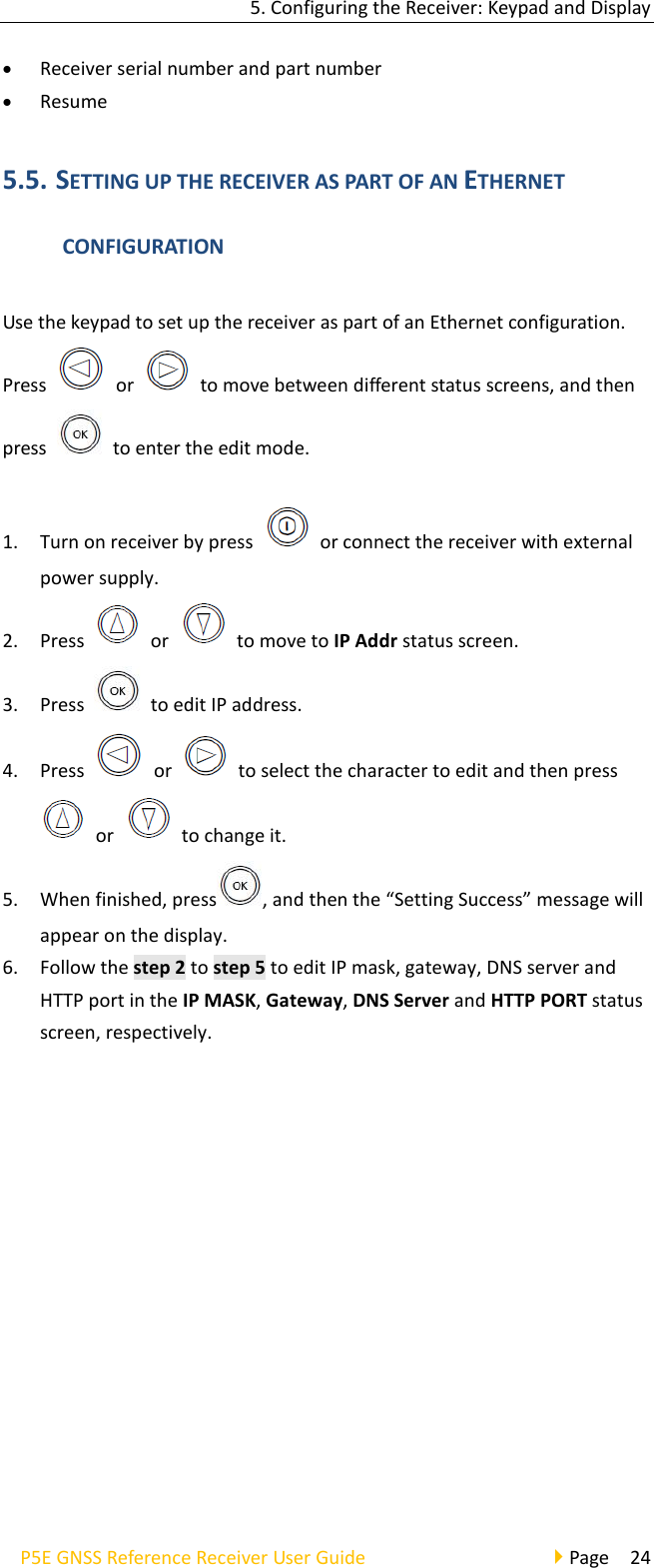
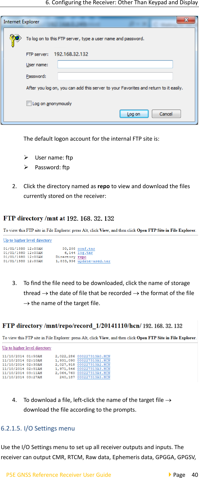
![6. Configuring the Receiver: Other Than Keypad and Display P5E GNSS Reference Receiver User Guide Page 39 To delete the recorded files of ANY storage thread, click the to the right of the required storage thread. To delete the recorded files of ALL storage threads, click [Clear All] button. • FTP Push Settings Use this screen to configure the receiver to push stored files to the FTP server of your choice. Only files that are configured to use FTP push are transmitted. Click to the right of the required FTP server and the FTP Push Settings screen appears: • FTP Push Recording Shows the related information about the recorded filed that be pushed. And users can click [Clear FTP Push Log] in the upper right corner to clear the status of FTP Push operations. • Data Download In this submenu, users can download the data files that recorded in the internal storage through the internal FTP site. 1. Click this submenu, and then the log on dialogue box will prompt you to enter a user name and password:](https://usermanual.wiki/Huace-Navigation-Technology/A020012/User-Guide-3907363-Page-40.png)
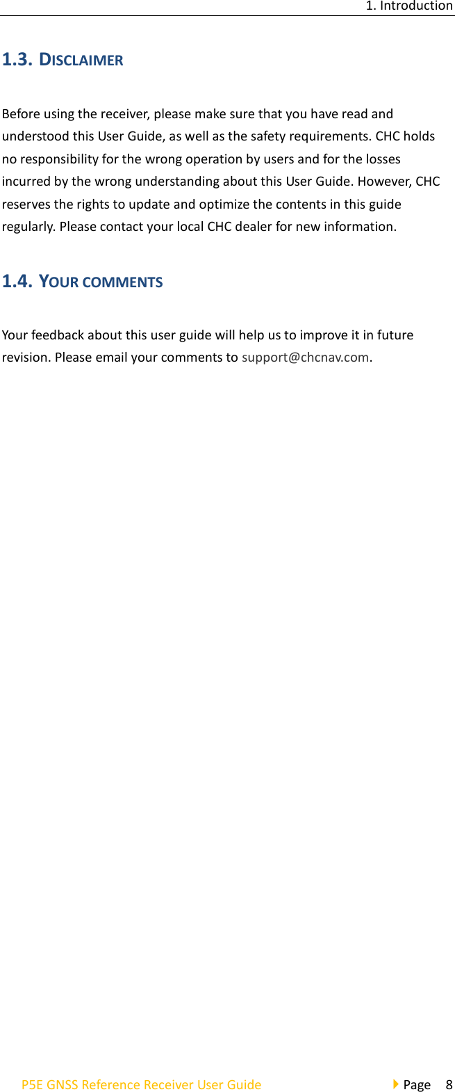
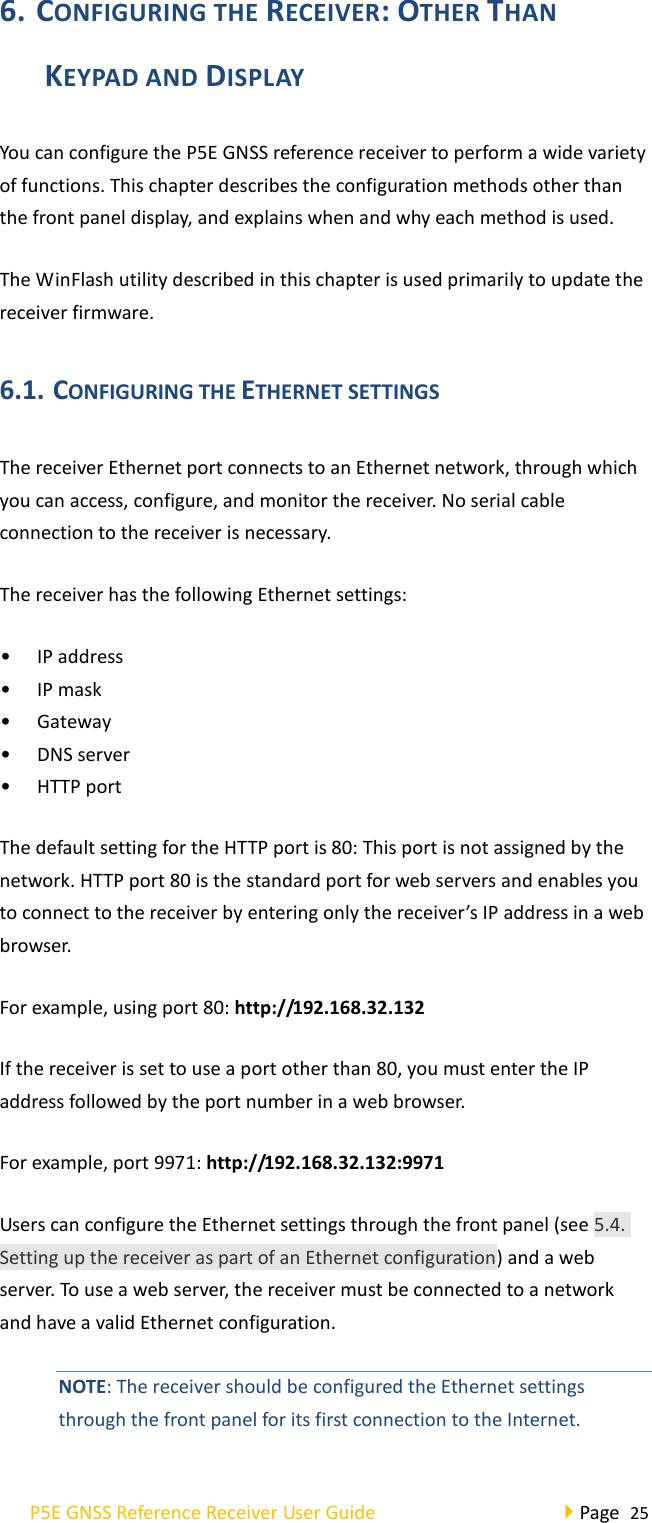
![6. Configuring the Receiver: Other Than Keypad and Display P5E GNSS Reference Receiver User Guide Page 41 on TCP/IP, UDP, serial port, or Bluetooth ports. • I/O Settings The following figure shows an example of the screen that appears when you select this submenu. In this submenu, users can configure 6 types of input and output settings. 1. RTK Client After configuring the settings of RTK client, users can log on CORS or APIS. Click the [Connect] button to the right the I/O Settings screen will appear choose one of the connection protocols among the NTRIP, APIS_BASE and APIS_ROVER configure the related parameters click [Confirm] to log on CORS or APIS. ➢ Connection Protocol: NTRIP](https://usermanual.wiki/Huace-Navigation-Technology/A020012/User-Guide-3907363-Page-42.png)
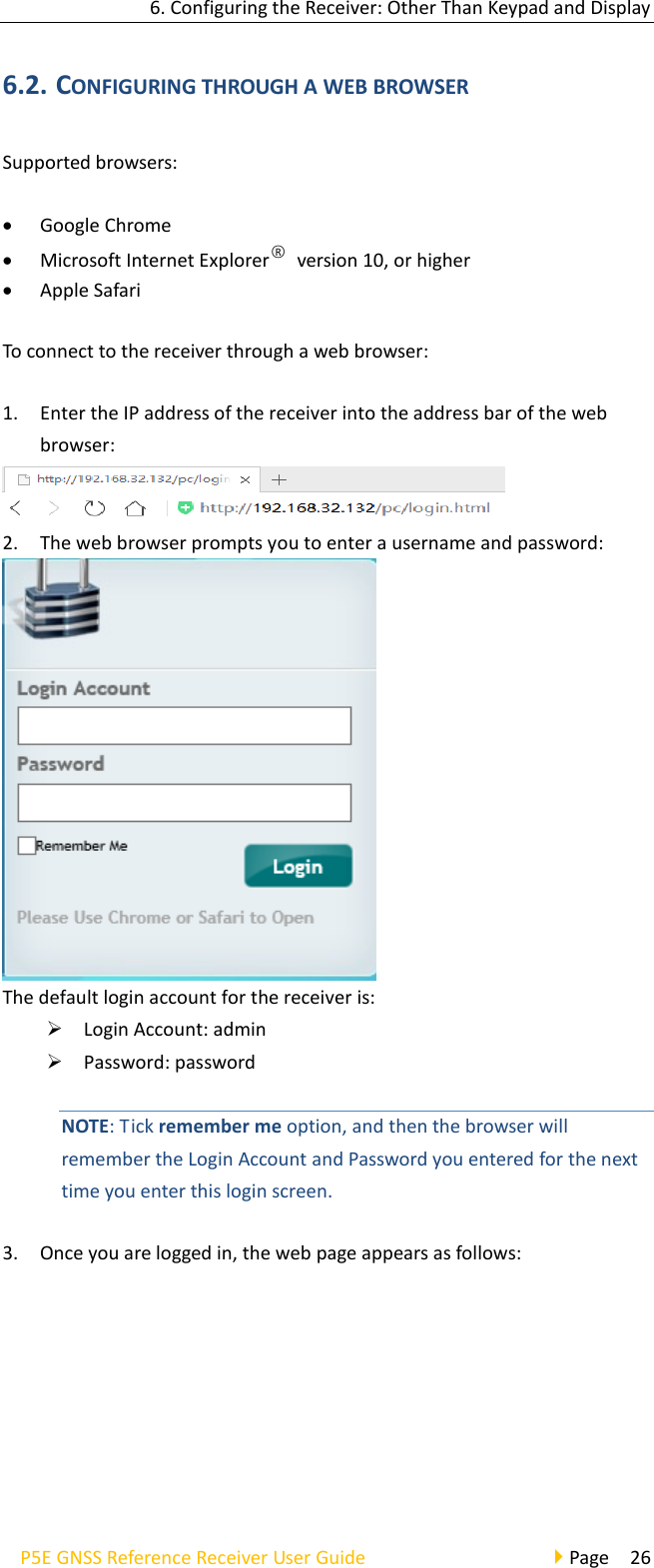
![6. Configuring the Receiver: Other Than Keypad and Display P5E GNSS Reference Receiver User Guide Page 42 ➢ Connection Protocol: APIS_BASE ➢ Connection Protocol: APIS_ROVER 2. TCP/UDP Client Click the [Connect]button to the right of required TCP/UDP Client the TCP/UDP Client screen will appear select the connection protocol from the dropdown list enter the IP and Port of the target server configure messages that you want to output to the target server click [Confirm] to save and complete the connection.](https://usermanual.wiki/Huace-Navigation-Technology/A020012/User-Guide-3907363-Page-43.png)
![6. Configuring the Receiver: Other Than Keypad and Display P5E GNSS Reference Receiver User Guide Page 43 NOTE: If the receiver and server are under the same Local Area Network (LAN), users can use the IP address in LAN of the server with any Port. However, if the receiver and server are under the two different LAN, users should use the public IP address of the server and configure the port mapping of the server. 3. TCP/IP Server Click the [Connect] button to the right of required TCP/IP Server the TCP Server/Ntrip Caster screen will appear select one of the connection protocols between NTRIP and TCP configure the other related parameters click [Confirm] to save the settings and open the server. ➢ Connection Protocol: NTRIP](https://usermanual.wiki/Huace-Navigation-Technology/A020012/User-Guide-3907363-Page-44.png)
![6. Configuring the Receiver: Other Than Keypad and Display P5E GNSS Reference Receiver User Guide Page 44 ➢ Connection Protocol: TCP 4. COM Port Click the [Settings] button to the right of required COM Port the Serial Port Setup screen will appear select Baud Rate used to transmit data configure the messages that you want to output through the serial port click [Confirm] to save the settings and start to transmit.](https://usermanual.wiki/Huace-Navigation-Technology/A020012/User-Guide-3907363-Page-45.png)
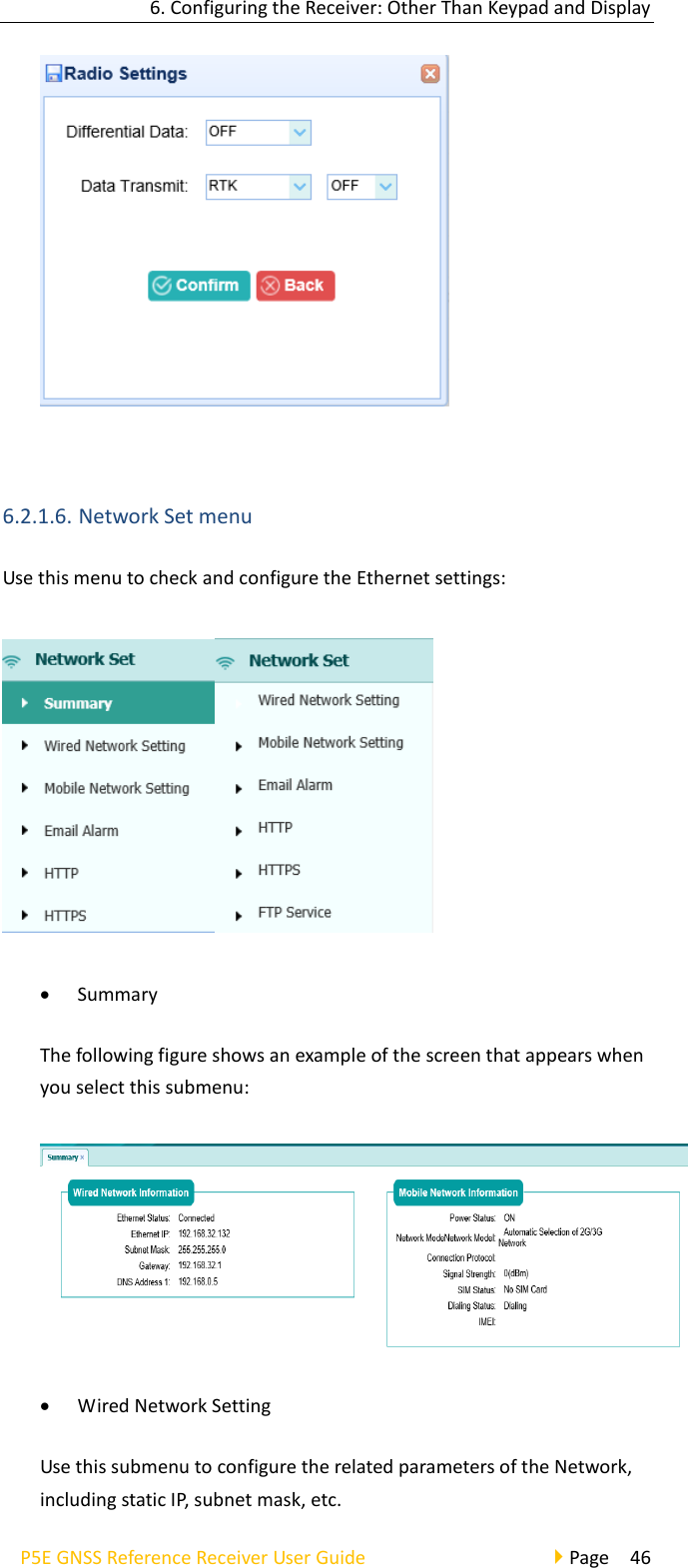
![6. Configuring the Receiver: Other Than Keypad and Display P5E GNSS Reference Receiver User Guide Page 45 5. Bluetooth Click the [Settings] button to the right of Bluetooth the Bluetooth Set screen will appear configure the messages that you want to transmit through Bluetooth click [Confirm] to save the settings and start to transmit. 6. Radio Click the [Settings] button to the right of Radio the Radio Settings screen will appear configure the messages that you want to transmit through Radio click [Confirm] to save the settings and start to transmit.](https://usermanual.wiki/Huace-Navigation-Technology/A020012/User-Guide-3907363-Page-46.png)
![6. Configuring the Receiver: Other Than Keypad and Display P5E GNSS Reference Receiver User Guide Page 53 following figure shows an example of the hardware information. • Config File In this submenu, users can download the configuration file by clicking [Download] button and determine a saving path to download the configuration file (.cfg file). Also, users can click the [Browse] button to locate the existing configuration file click [Confirm] button to confirm the selected file and start updating. • System Log Use this submenu to download the system log of the receiver. • User Log Use this submenu to tick which log files and download the user log of](https://usermanual.wiki/Huace-Navigation-Technology/A020012/User-Guide-3907363-Page-54.png)
![6. Configuring the Receiver: Other Than Keypad and Display P5E GNSS Reference Receiver User Guide Page 54 the receiver. • Firmware Update Use this submenu to load new firmware to the receiver across the network. Click the [Browse] button to locate the upgrade file click [Confirm] button to confirm the selected upgrading file and start upgrading. NOTE: It will take about 2 or 3 minutes to complete the firmware upgrading. • Board Upgrade Use this submenu to upgrade board. Click [Browse] to choose upgrade files and Click [Confirm] to upgrade.](https://usermanual.wiki/Huace-Navigation-Technology/A020012/User-Guide-3907363-Page-55.png)
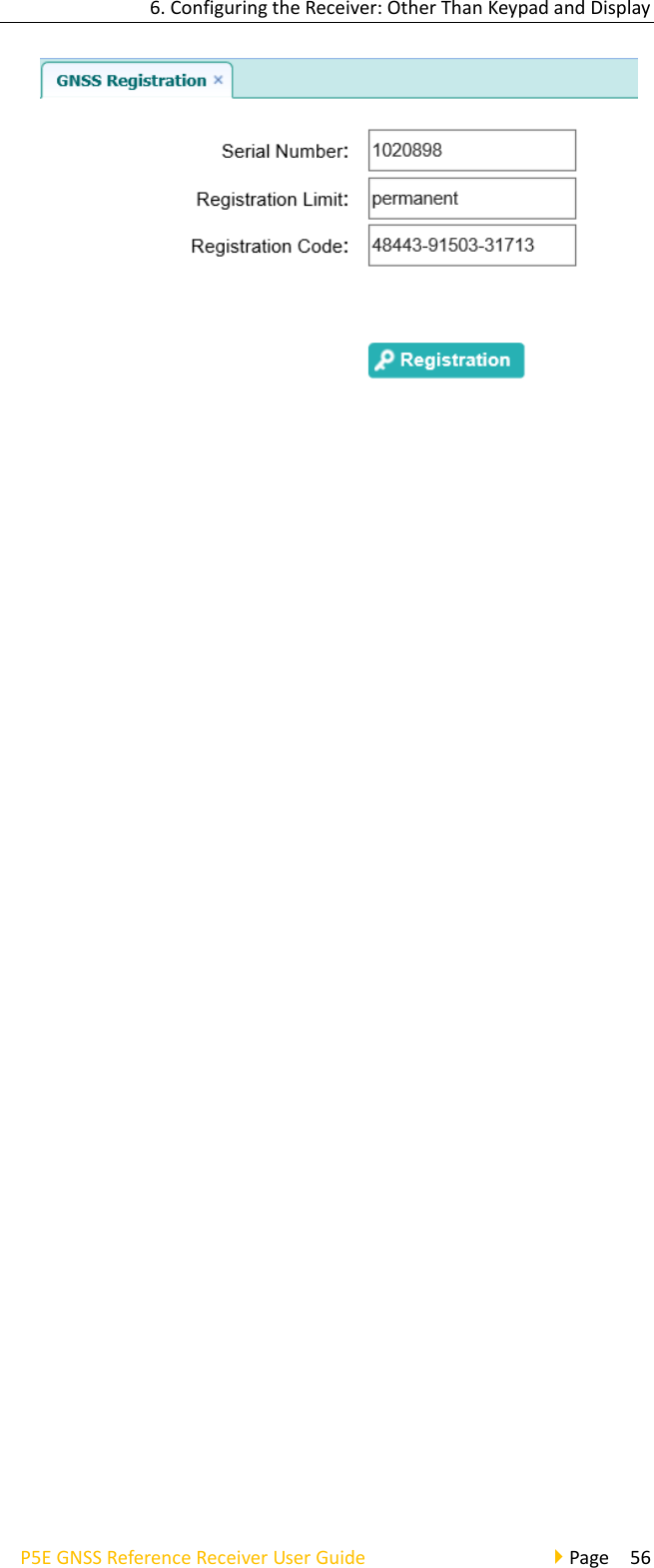
![6. Configuring the Receiver: Other Than Keypad and Display P5E GNSS Reference Receiver User Guide Page 55 • Radio Upgrade Use this submenu to upgrade radio. Click [Browse] to choose upgrade files and Click [Confirm] to upgrade. • Upgrade Online • GNSS Registration Use this submenu to register the receiver. Paste or enter the registration code to the Registration Code field click [Registration] button to complete the registration.](https://usermanual.wiki/Huace-Navigation-Technology/A020012/User-Guide-3907363-Page-56.png)
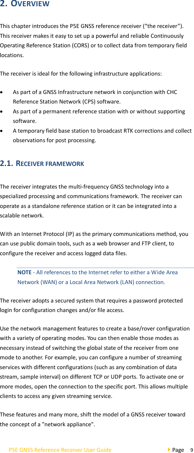
![P5E GNSS Reference Receiver User Guide Page 57 7. DEFAULT SETTING AND CONFIGURATION FILES Most of the receiver settings are stored in application files. The default application file, Default.cfg, is stored permanently in the receiver, and contains the factory default settings for the P5E GNSS reference receiver. Whenever the receiver is reset to its factory defaults, the current settings (stored in the current configuration file, copy.cfg) are reset to the values in the default application file. The P5E GNSS reference receiver extends the use of configuration files to allow simplified receiver setting duplication in multiple receivers. This is sometimes referred to as receiver cloning and is very useful when preparing a large group of receivers for a field data collection campaign. 7.1. DEFAULT RECEIVER SETTINGS Function Factory default values SV Enable All SVs enabled General controls Elevation mask PDOP mask 0° 6 Lemo port Baud rate Format Flow control 9600 8-None-1 None DB9 port Baud rate Format Flow control 9600 8-None-1 None Log status OFF Differential data OFF Raw data OFF Ephemeris data OFF NMEA (GPGGA, GPGSV) OFF Reference position Latitude Longitude Height 0°0’0.00000000’’ 0°0’0.00000000’’ 0.000 Antenna Type Measure Method Height None 2.0000 (Meter) Antenna Phase Center 7.1.1. RESETTING THE RECEIVER TO FACTORY DEFAULTS Log in the web page of the receiver tap and unfold the Receiver Reset menu tap the Receiver Reset submenu click the [Confirm] button to the right of Reset to Defaults field.](https://usermanual.wiki/Huace-Navigation-Technology/A020012/User-Guide-3907363-Page-58.png)
![8. Specifications P5E GNSS Reference Receiver User Guide Page 58 7.1.2. USING CONFIGURATION FILES TO DUPLICATE RECEIVER SETTINGS The P5E GNSS reference receiver allows the extensive use of application files in order to retain a unique receiver configuration. With this receiver, you can create a configuration file that includes most of the receiver's unique configuration settings. You can then update that configuration file onto one or more other P5E GNSS reference receivers to quickly configure them to match the receiver which creates that configuration file. NOTE: The configuration file includes most of the configuration settings except IP Address, IP Mask, Gateway and DNS Server. This is called receiver configuration cloning or cloning. Receiver cloning greatly reduces the time required to prepare a large group of receivers for field operations. Log in the web page of the receiver tap and unfold the Firmware menu tap the Config File submenu click the [Browse] button to locate the existing configuration file click [Confirm] button to confirm the selected file and start updating. 8. SPECIFICATIONS](https://usermanual.wiki/Huace-Navigation-Technology/A020012/User-Guide-3907363-Page-59.png)