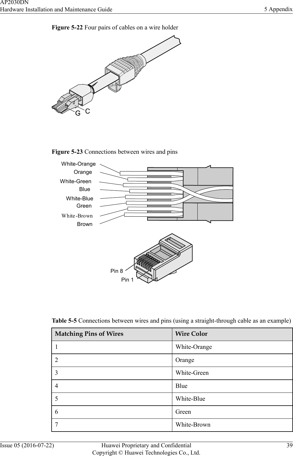
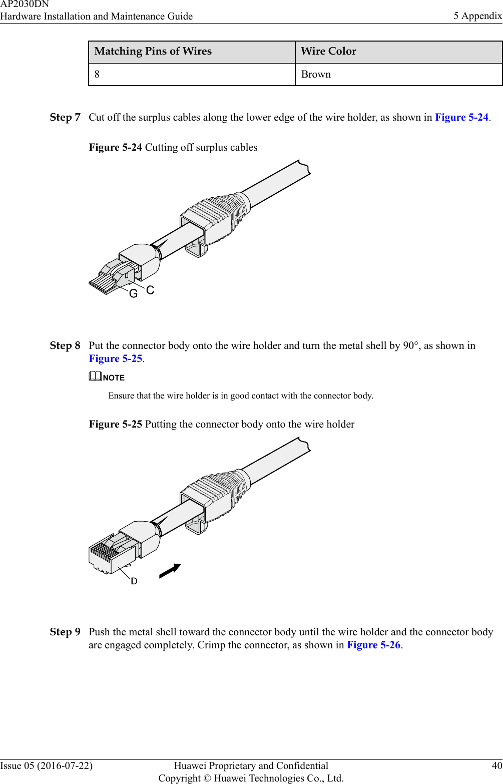
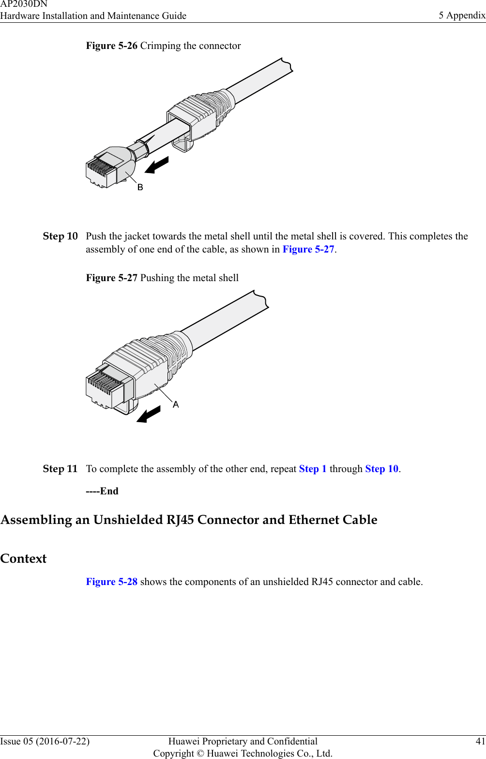
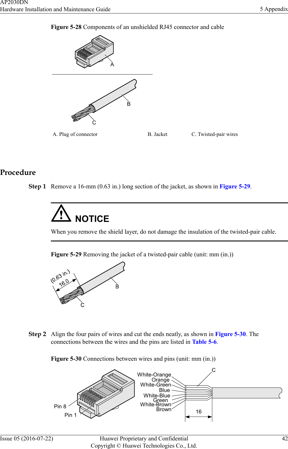
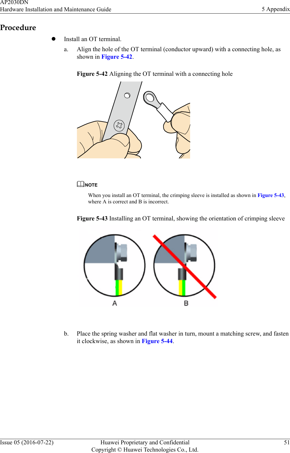
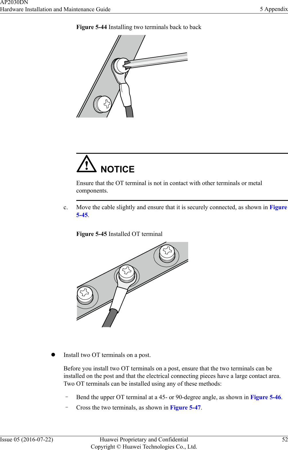
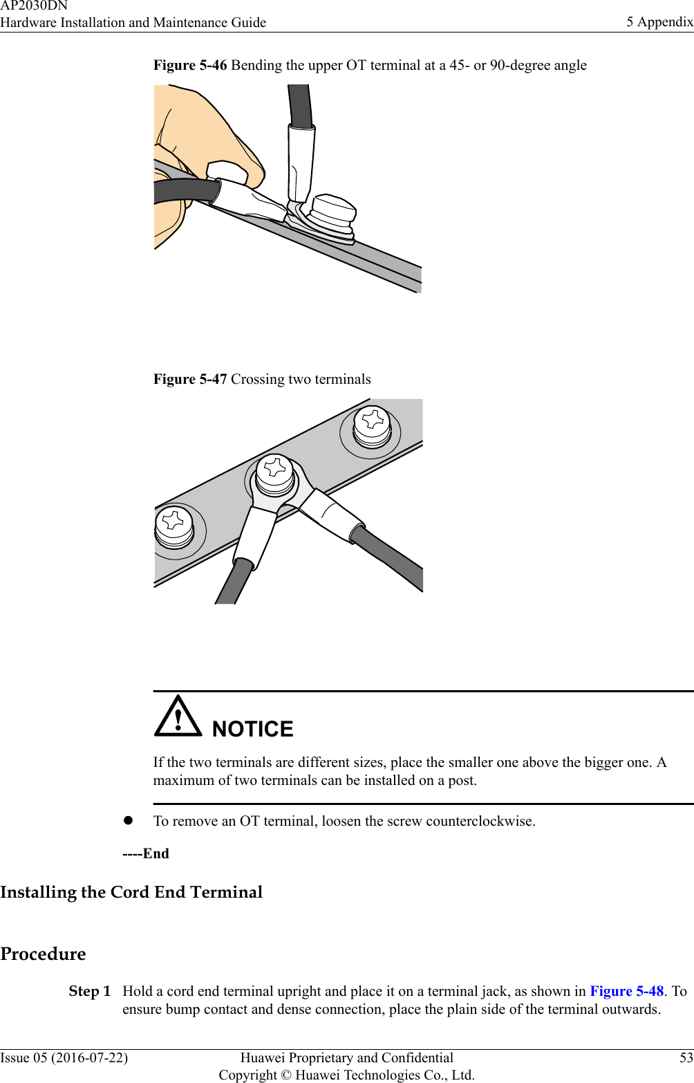
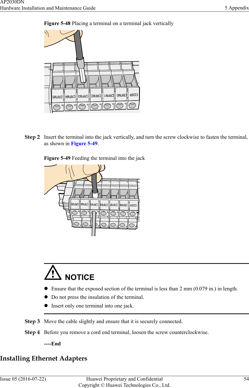
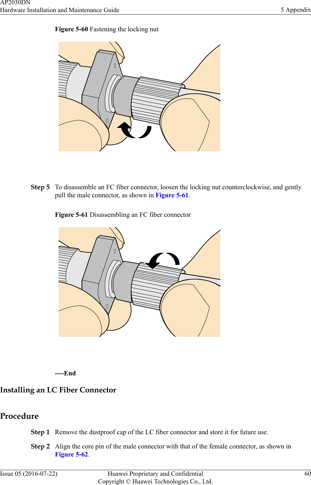
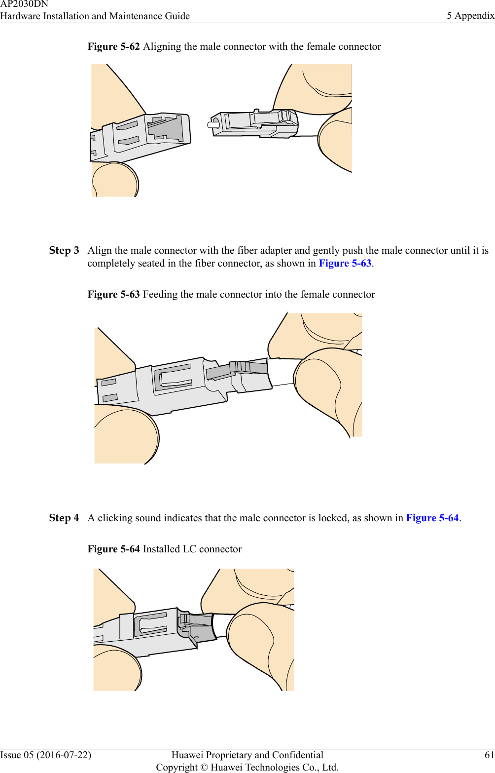
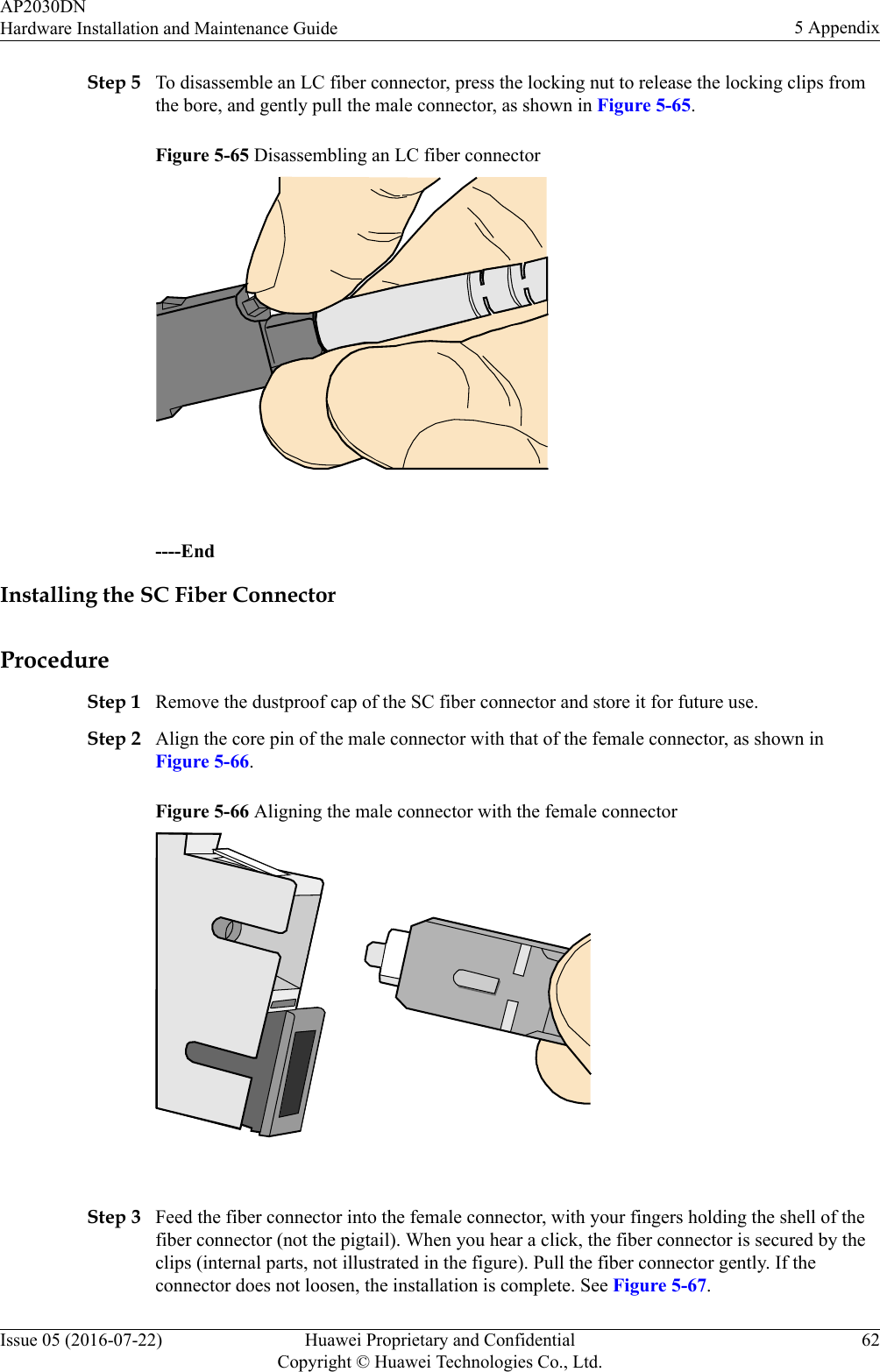
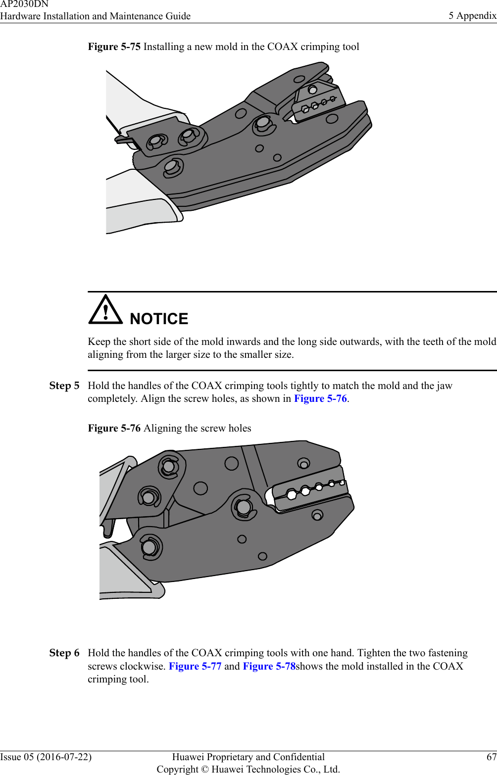
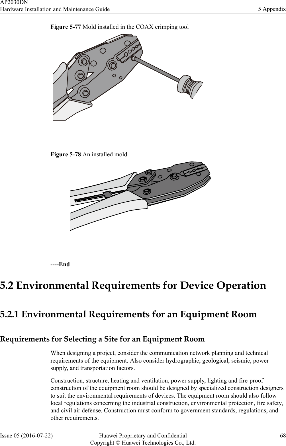
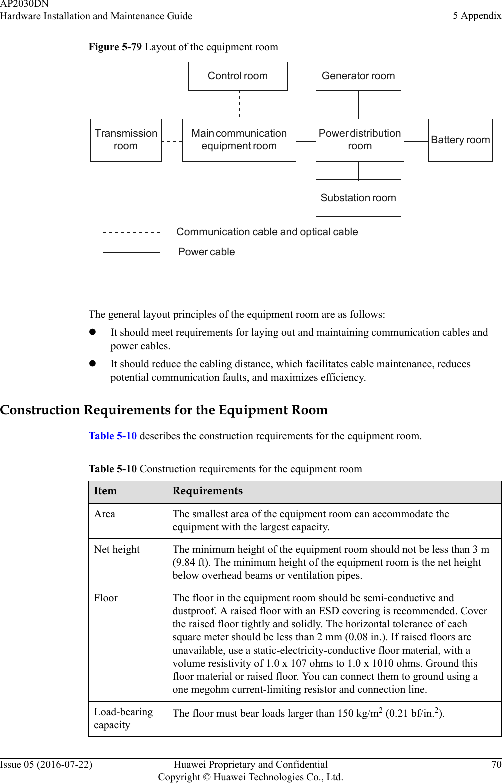
Huawei Technologies AP2030DN Wireless LAN Access Point User Manual Hardware Installation and Maintenance Guide
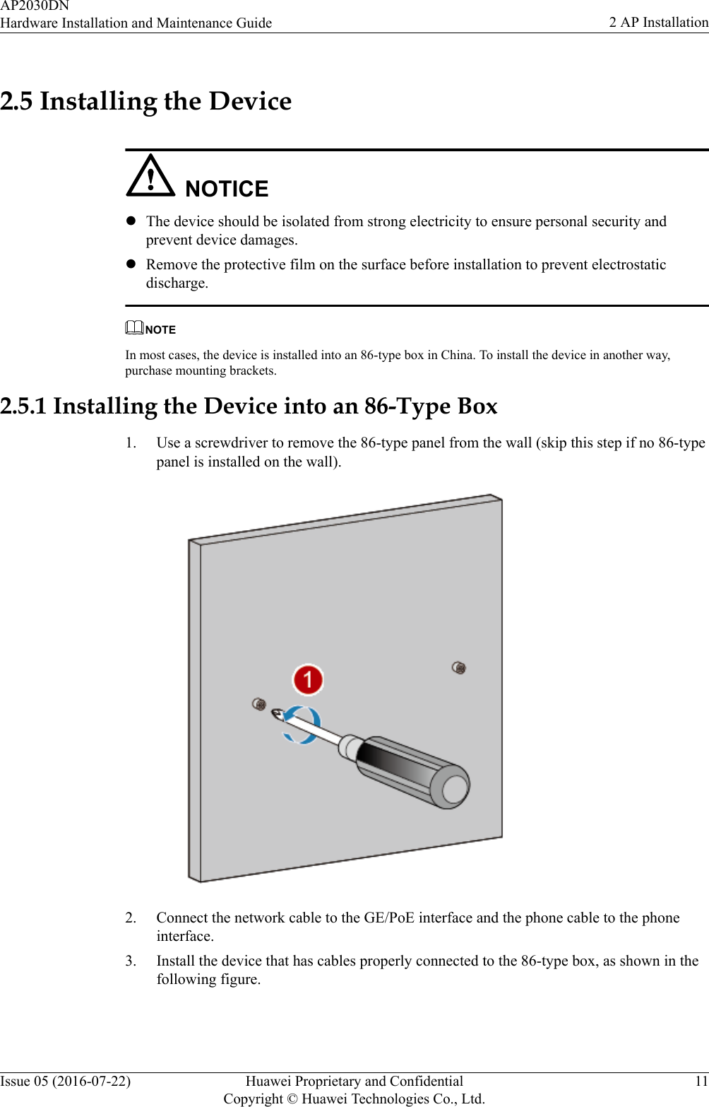
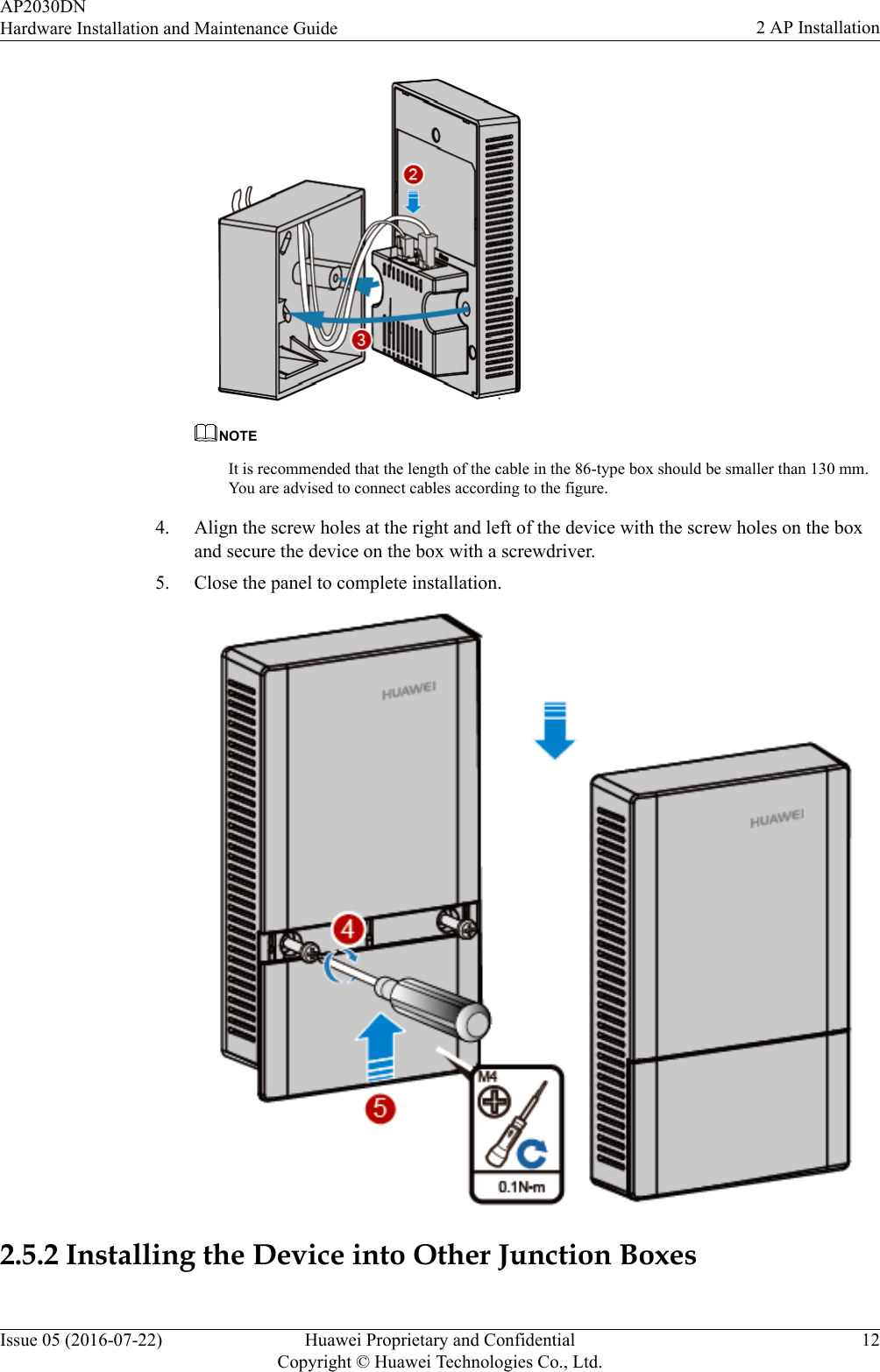
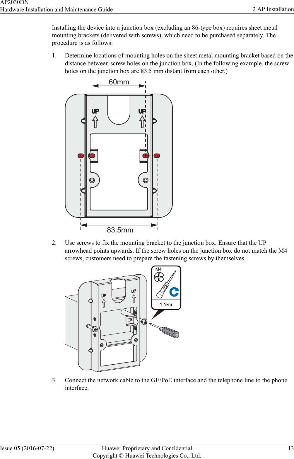
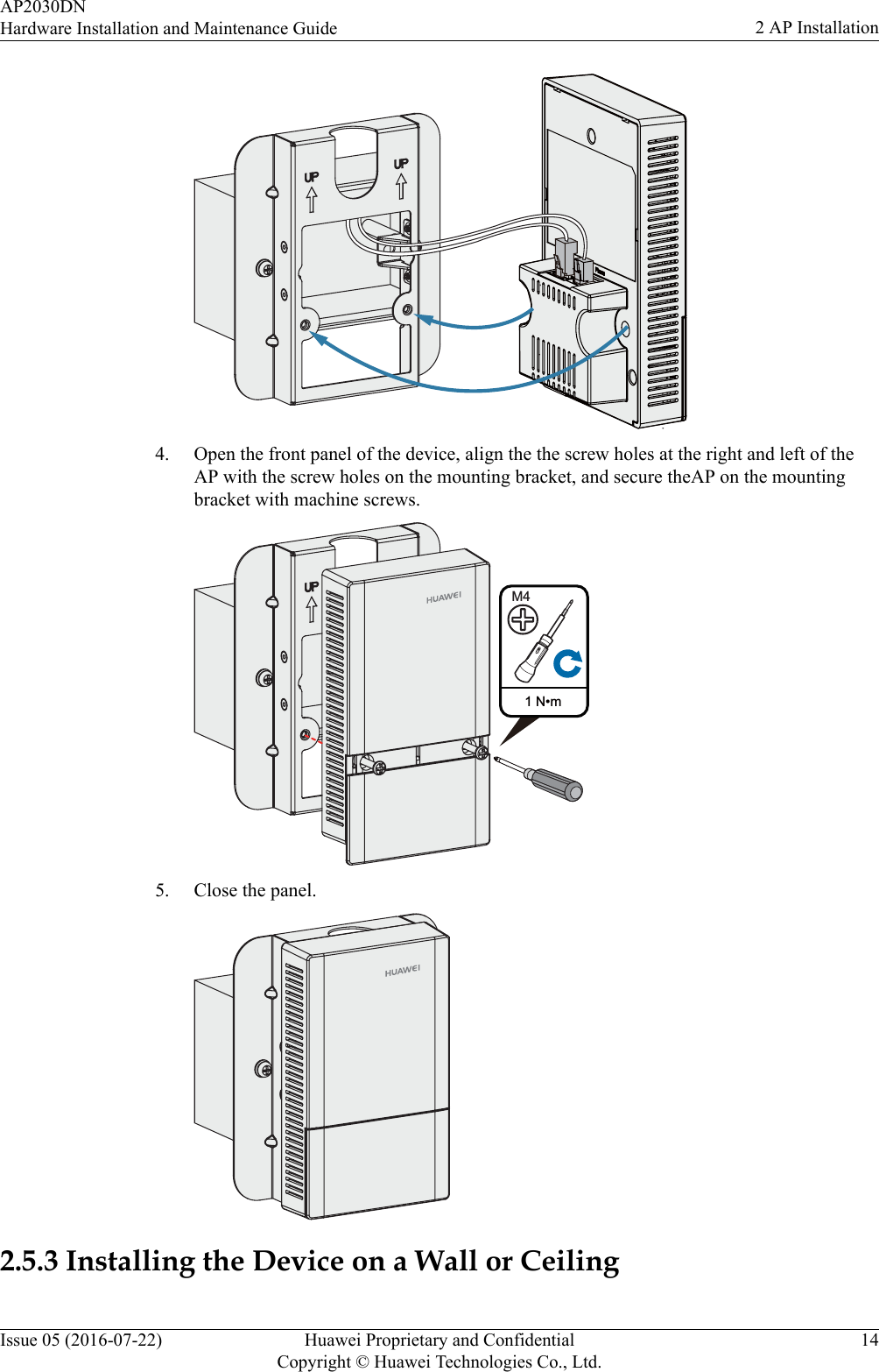
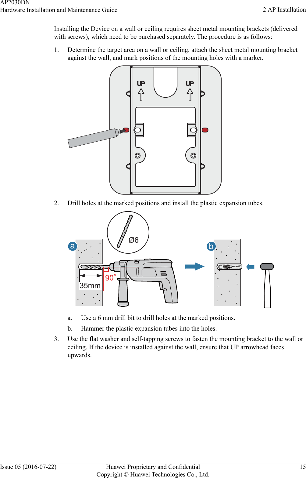
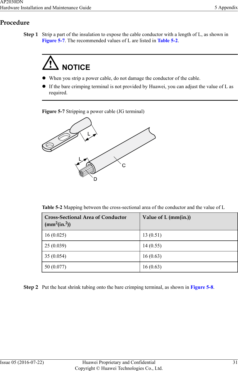
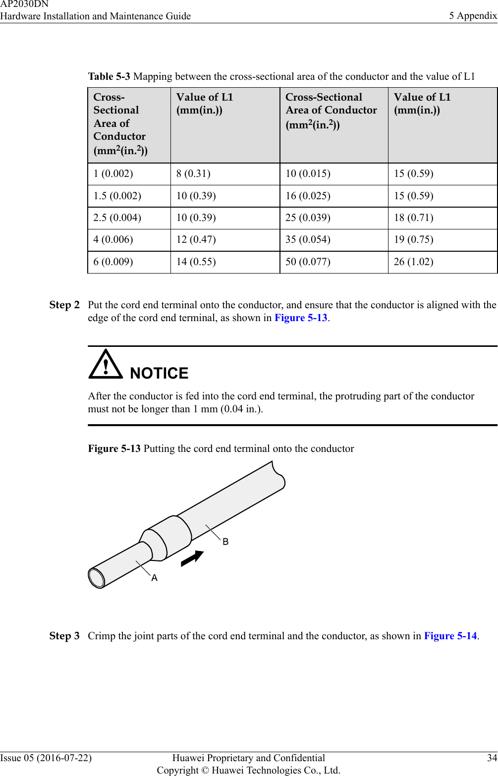
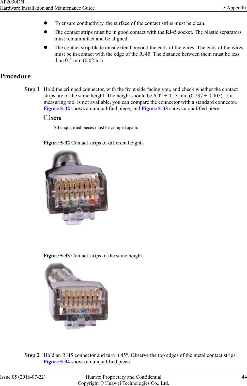
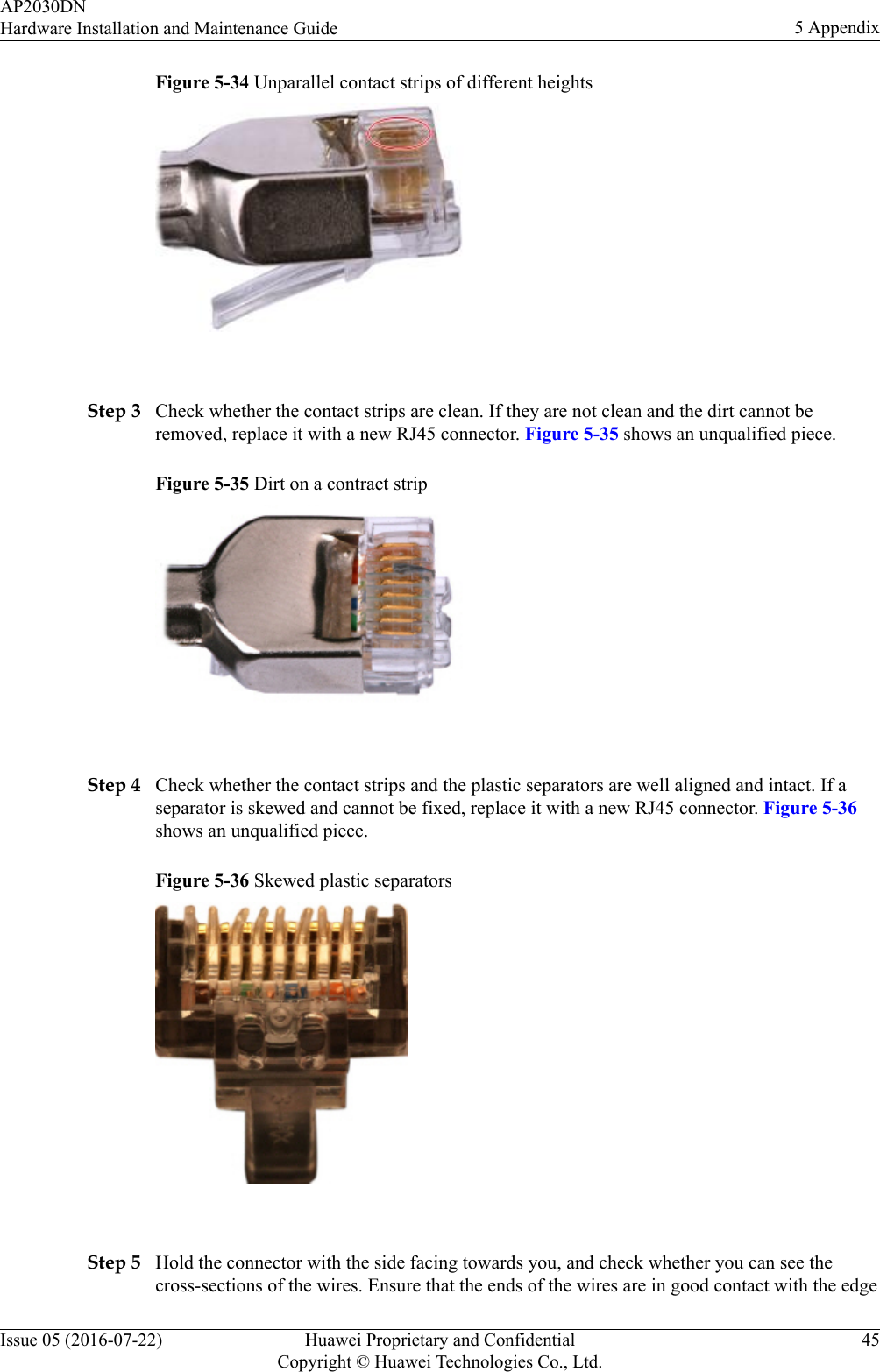
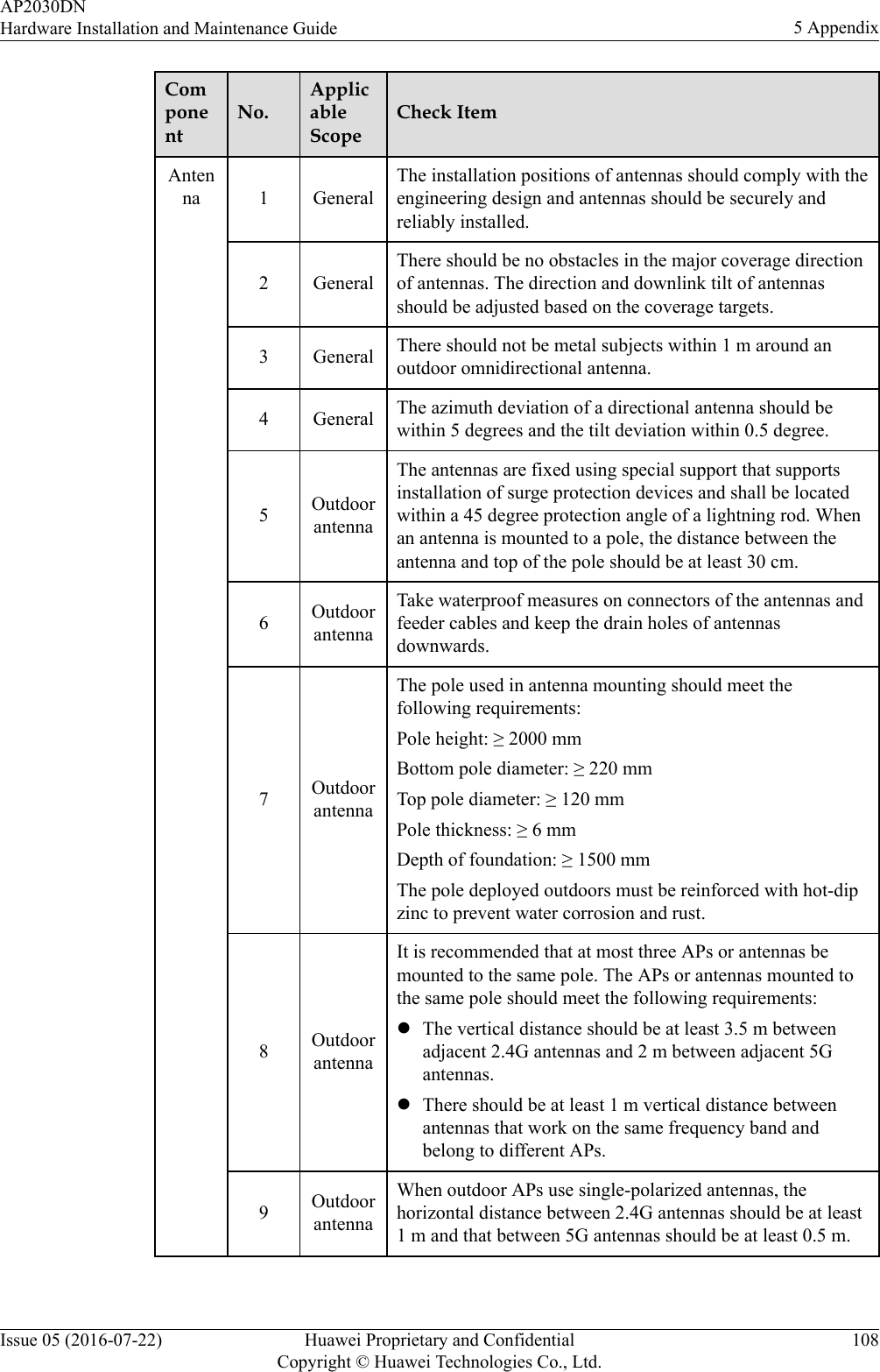
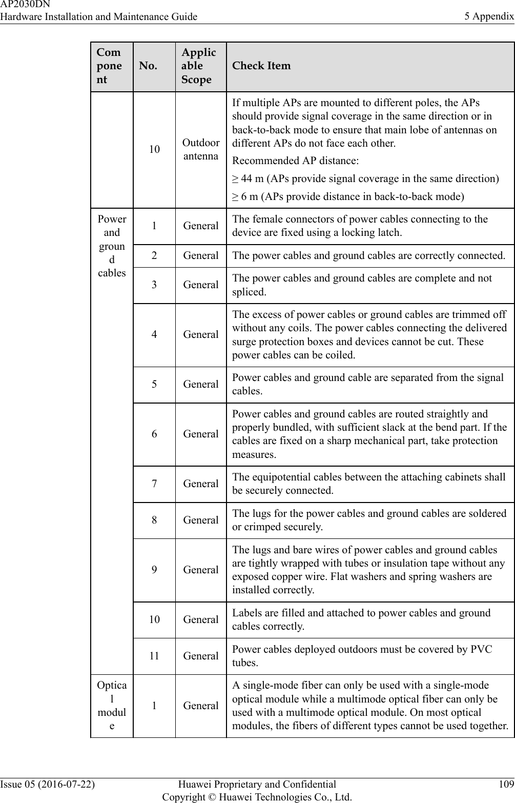
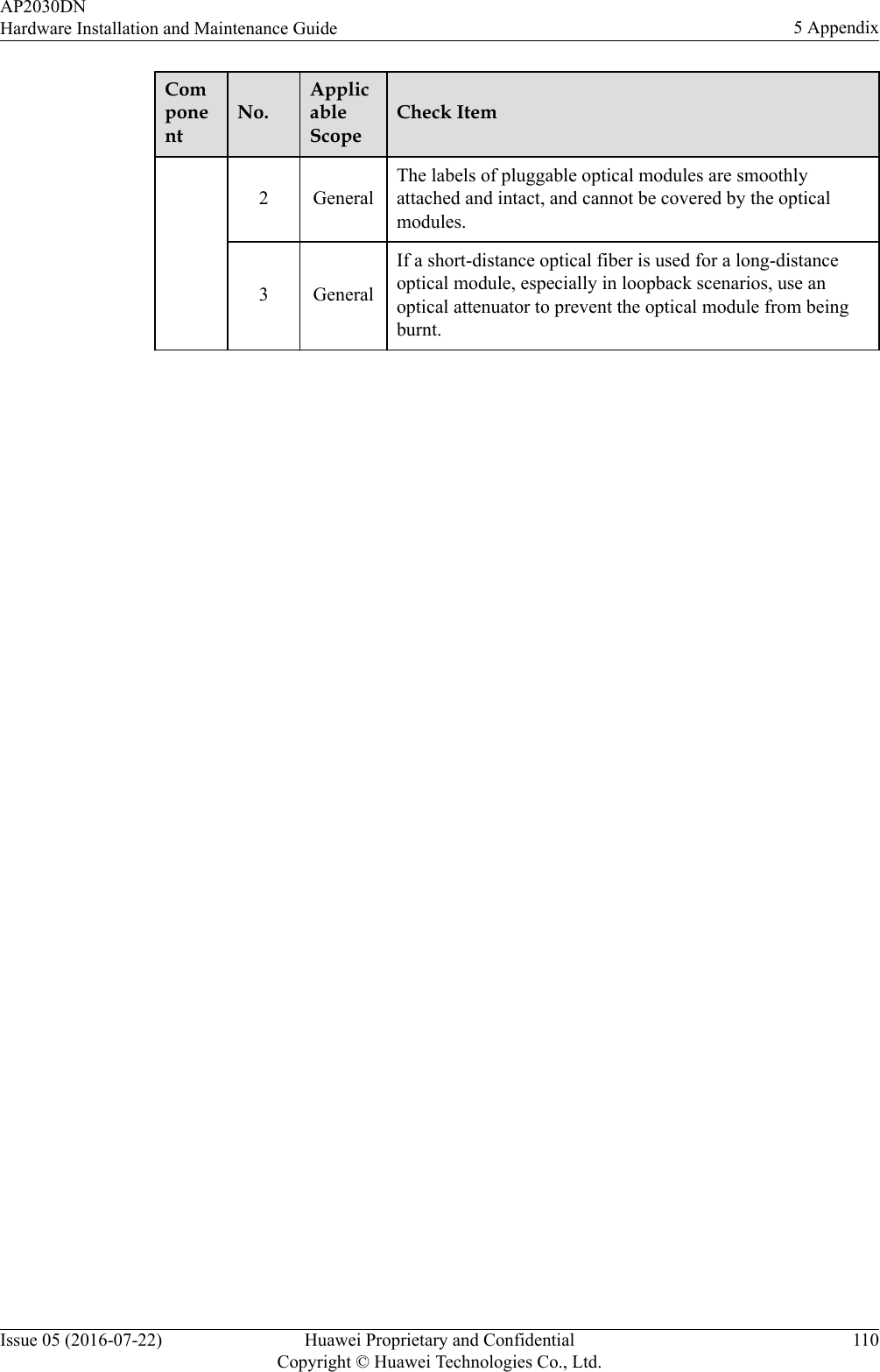
Huawei Technologies Co.,Ltd Wireless LAN Access Point Hardware Installation and Maintenance Guide
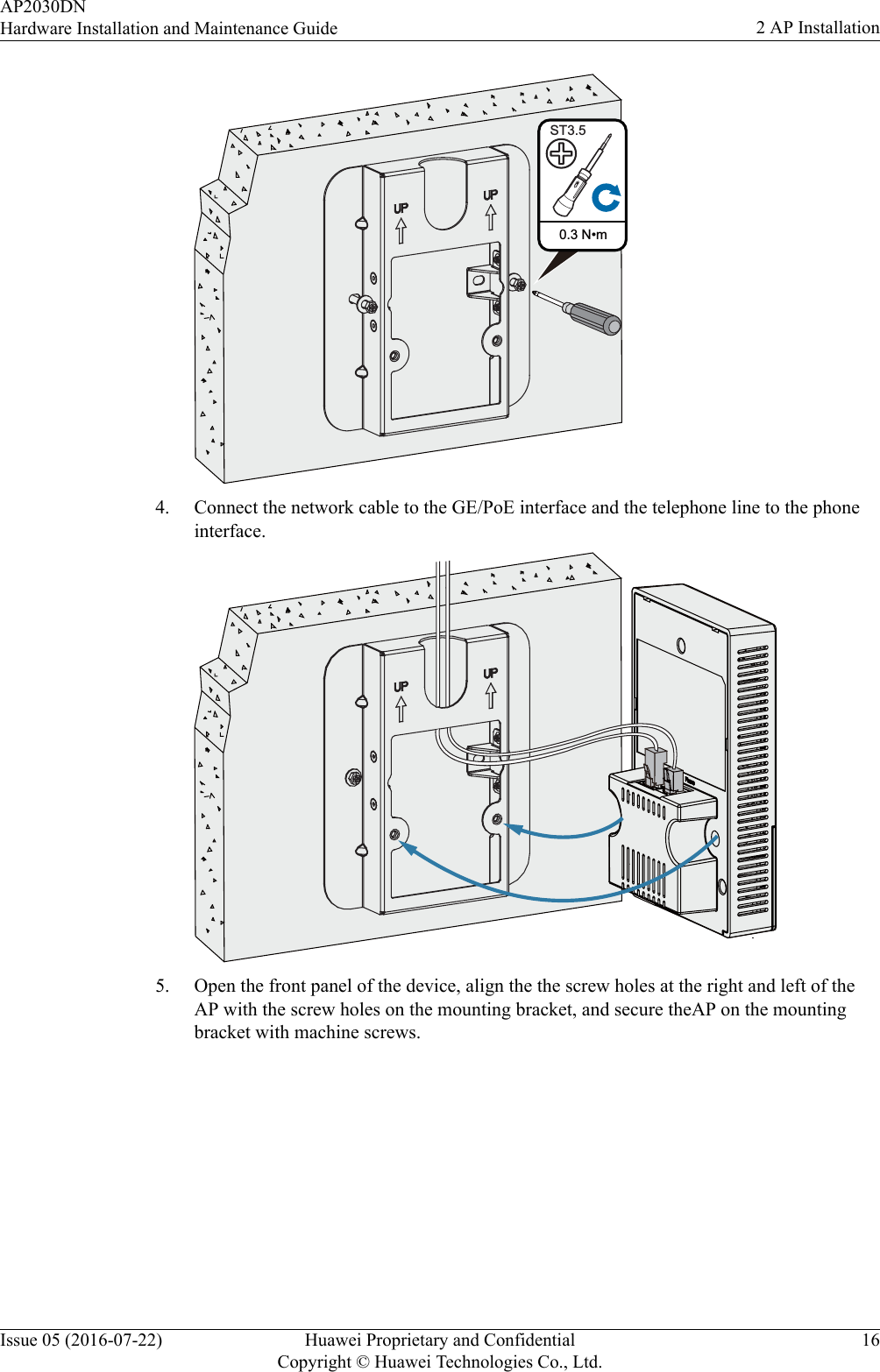
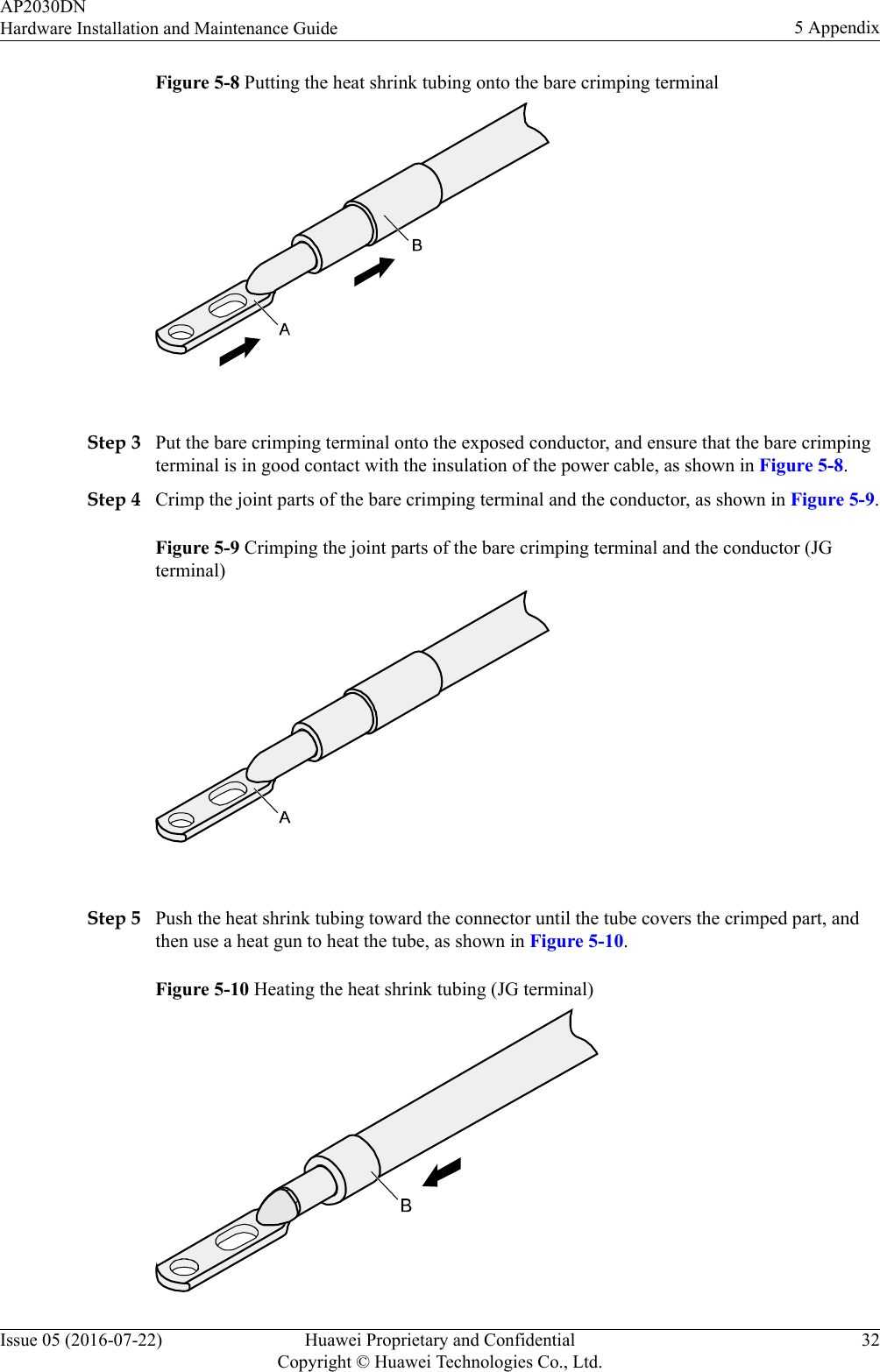
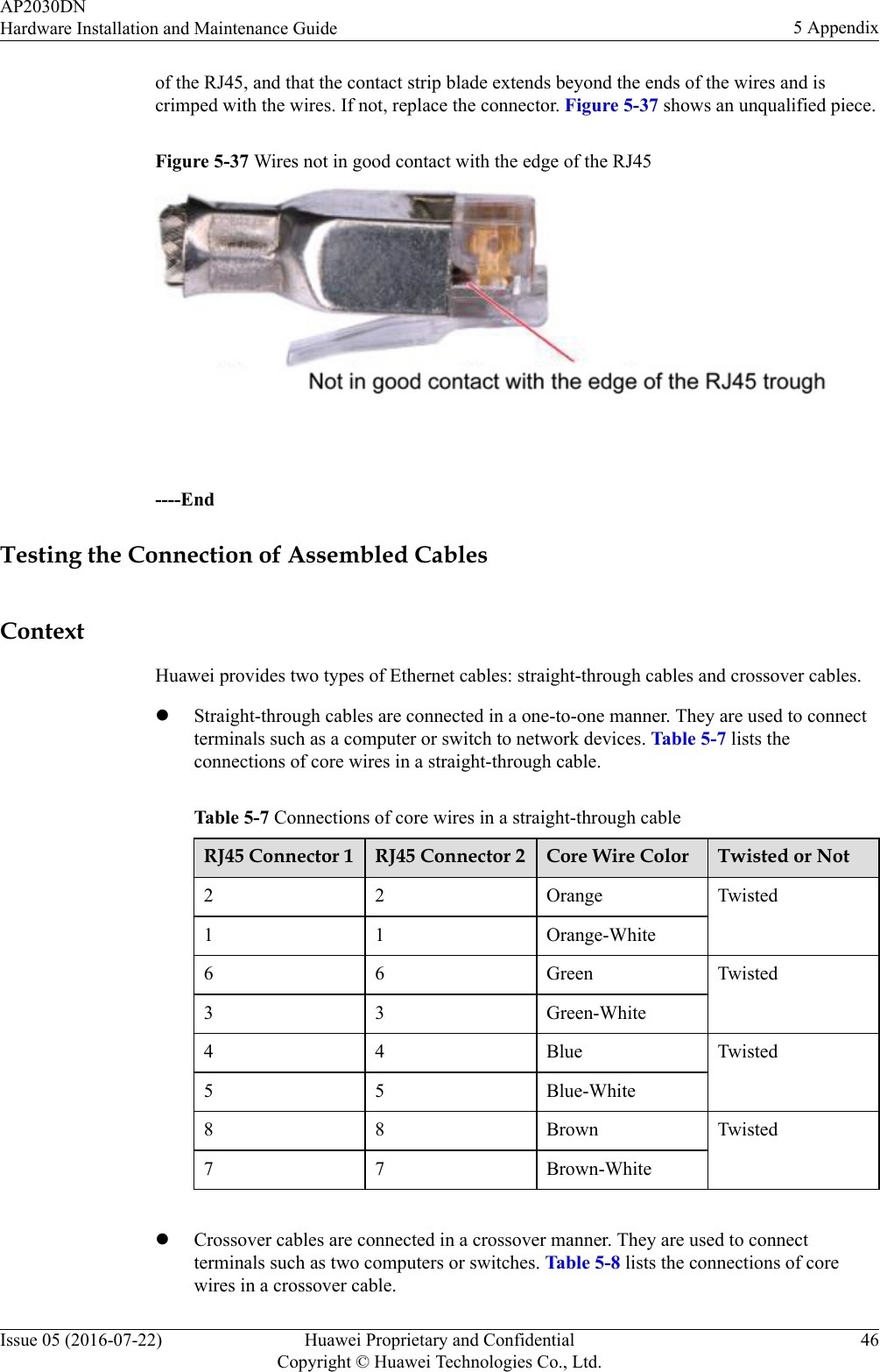
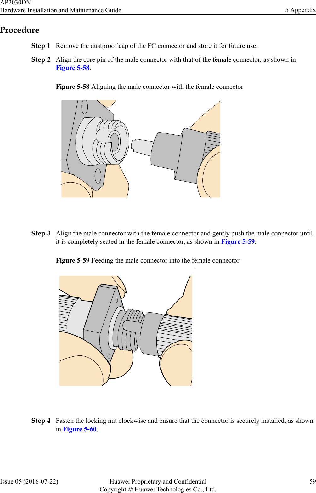
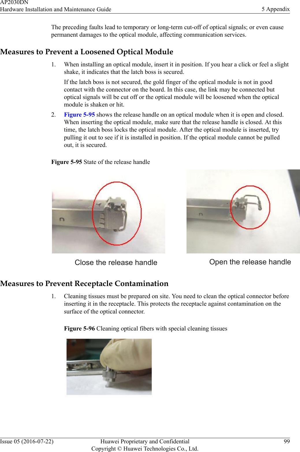
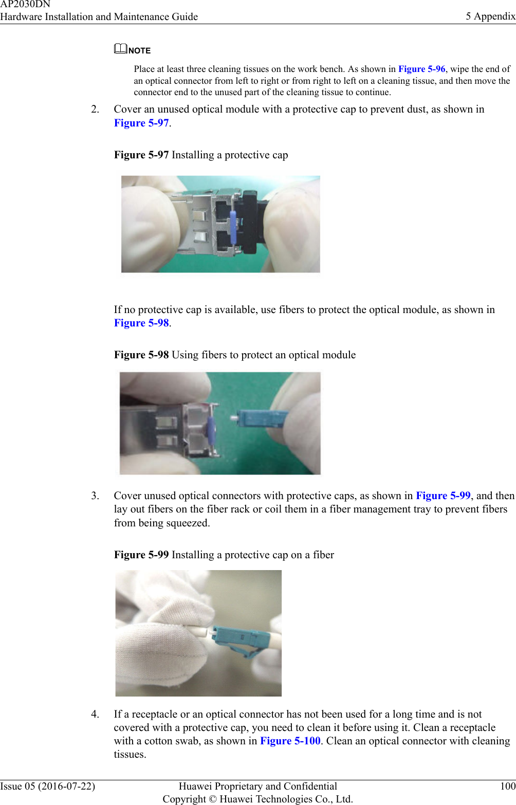
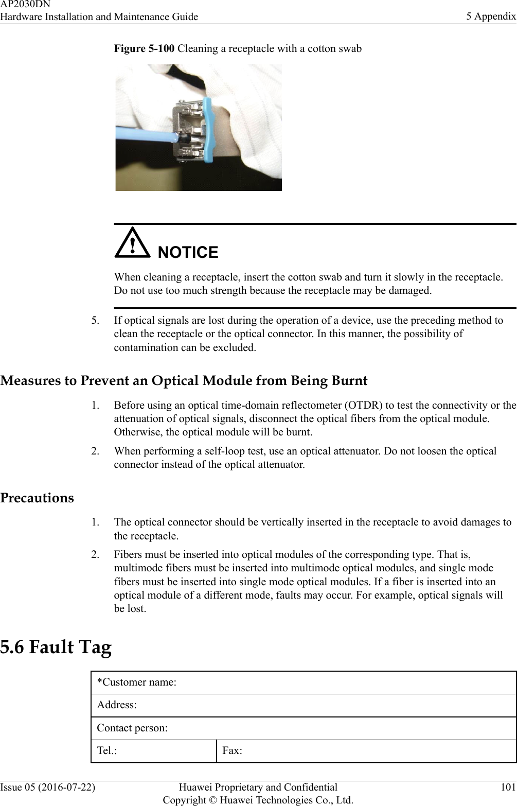
Contents
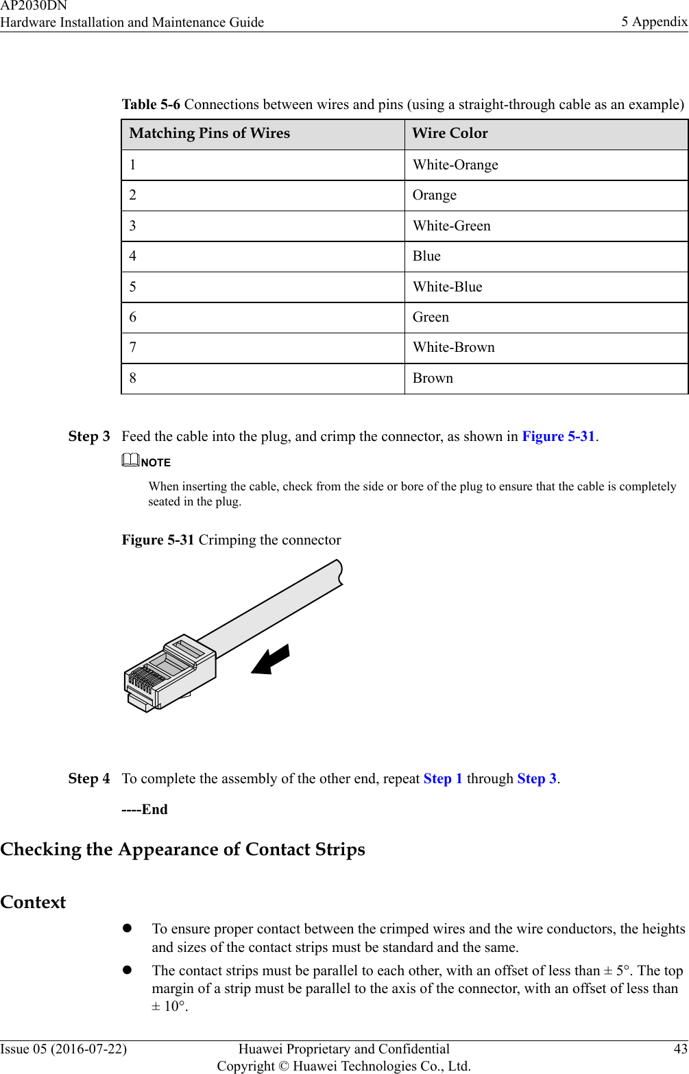
- 1. Users Manual
- 2. Regulatory Compliance Statement
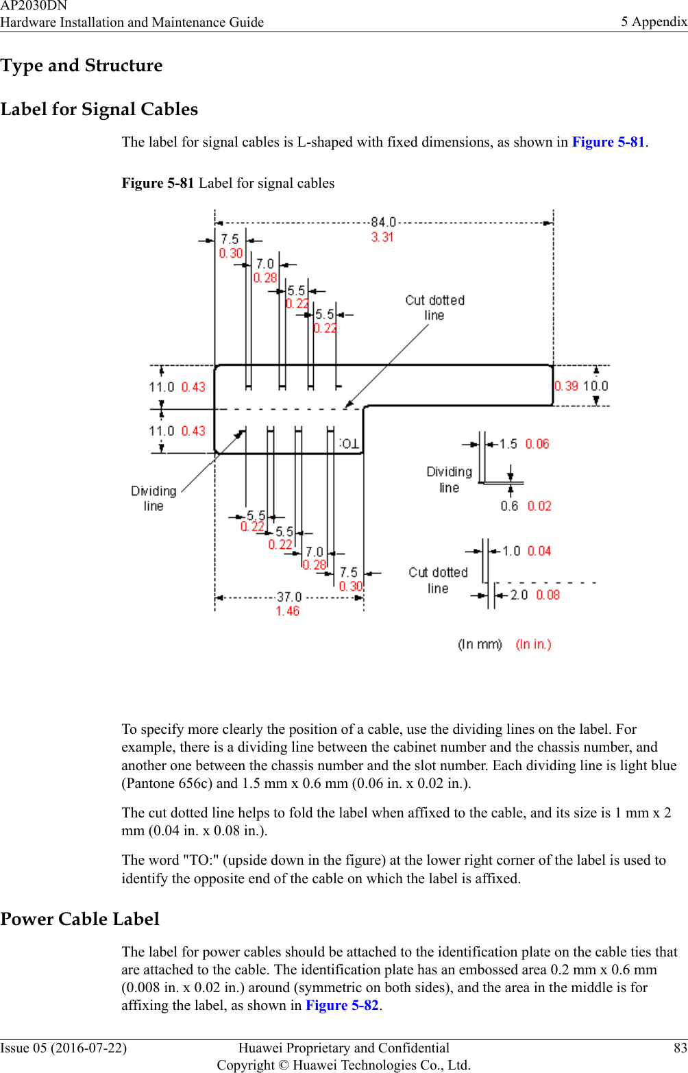
Users Manual