Huawei Technologies AP4050DN-HD Wireless LAN Access Point User Manual AP4050DN HD Hardware Installation and Maintenance Guide
Huawei Technologies Co.,Ltd Wireless LAN Access Point AP4050DN HD Hardware Installation and Maintenance Guide
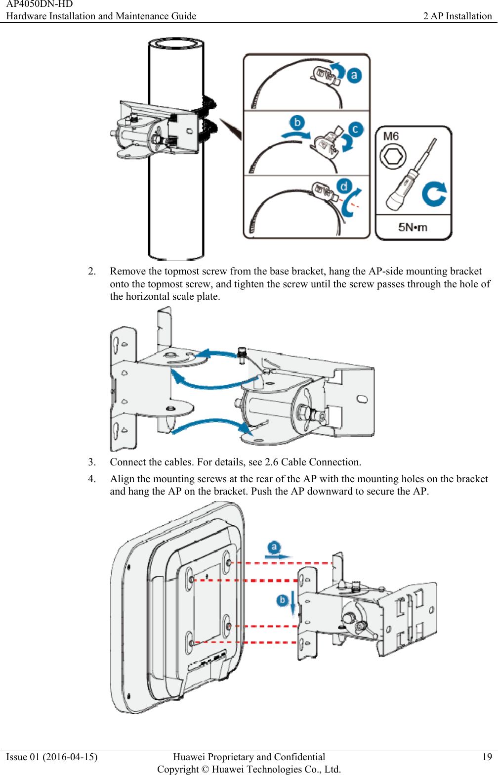
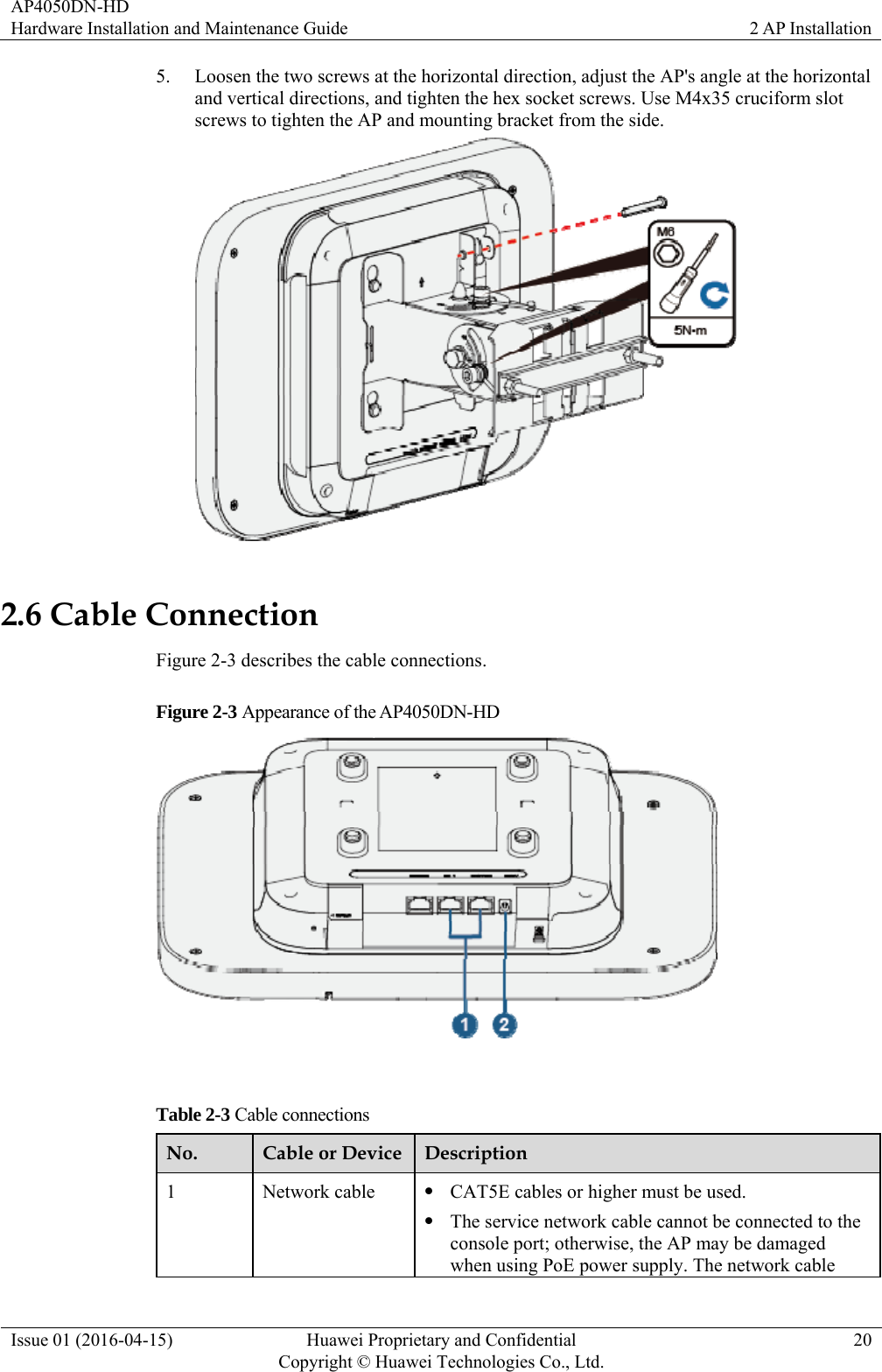
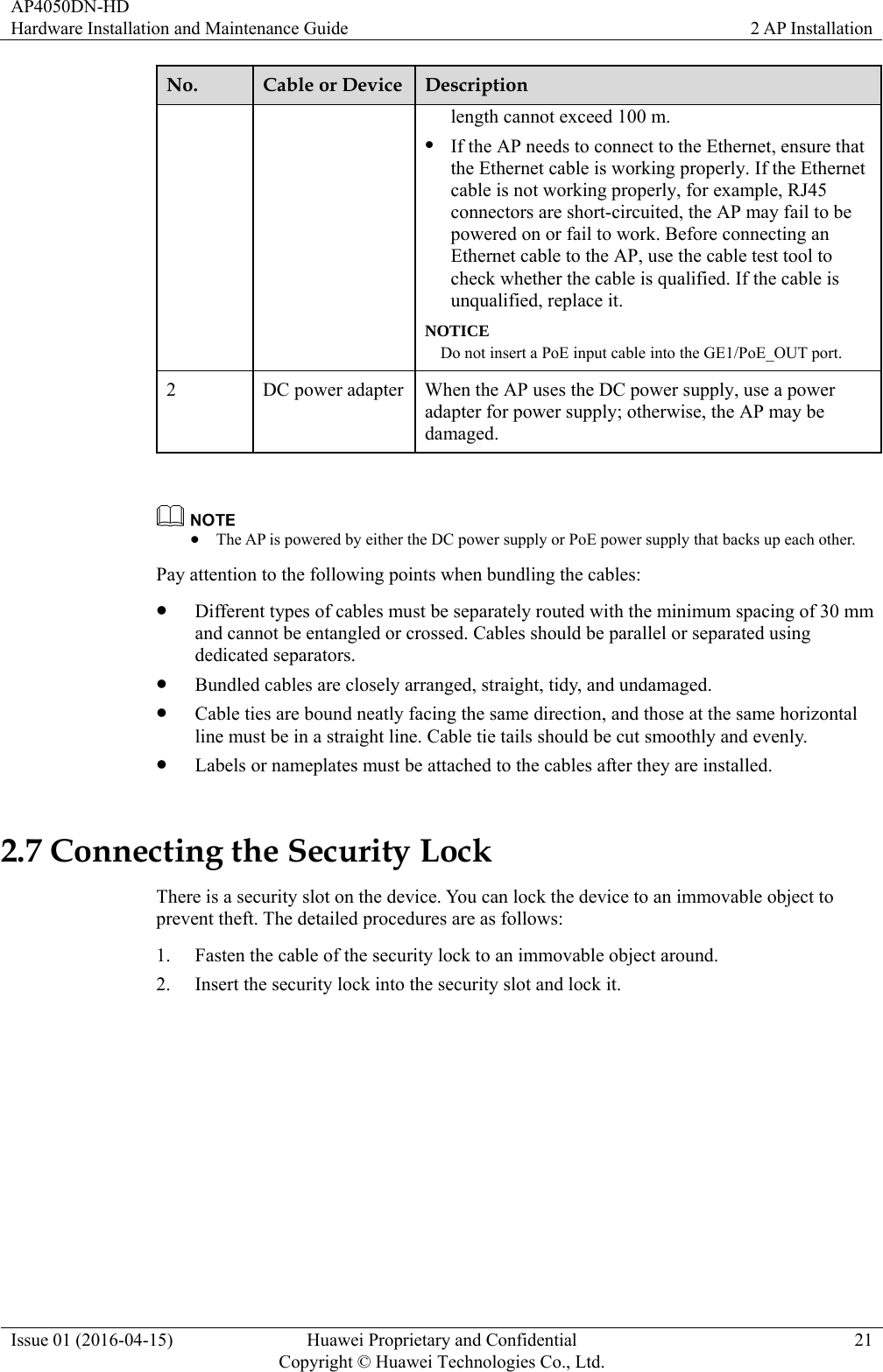
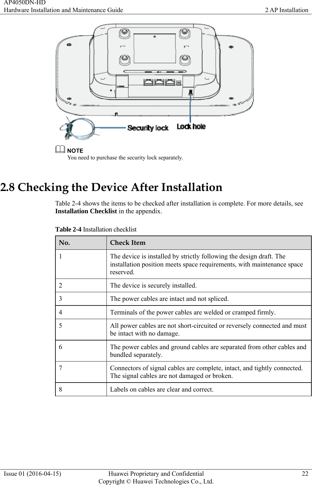
Contents
- 1. User Manual
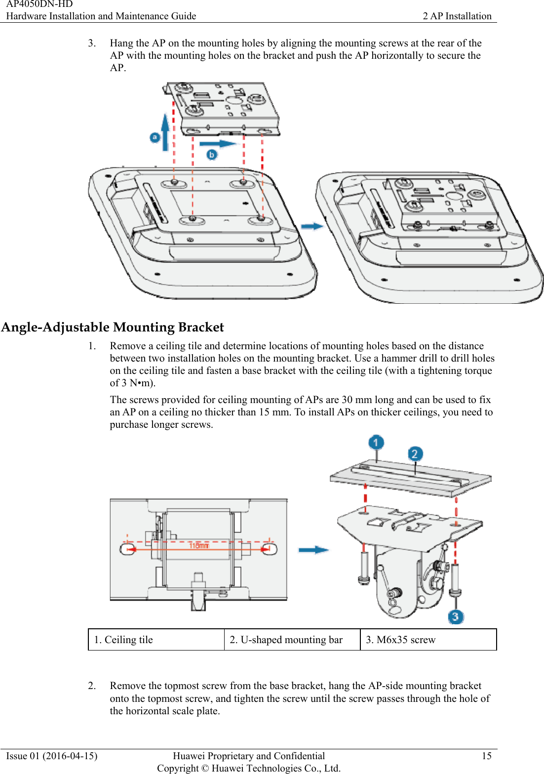
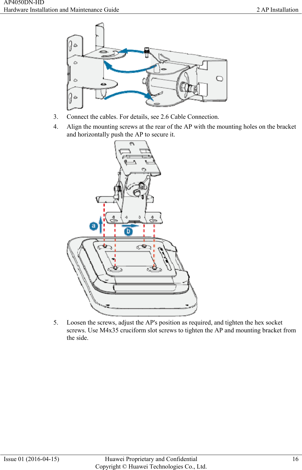
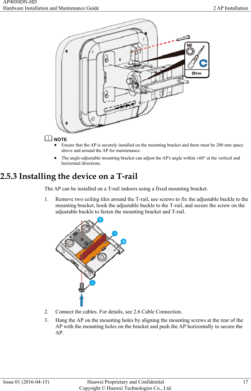
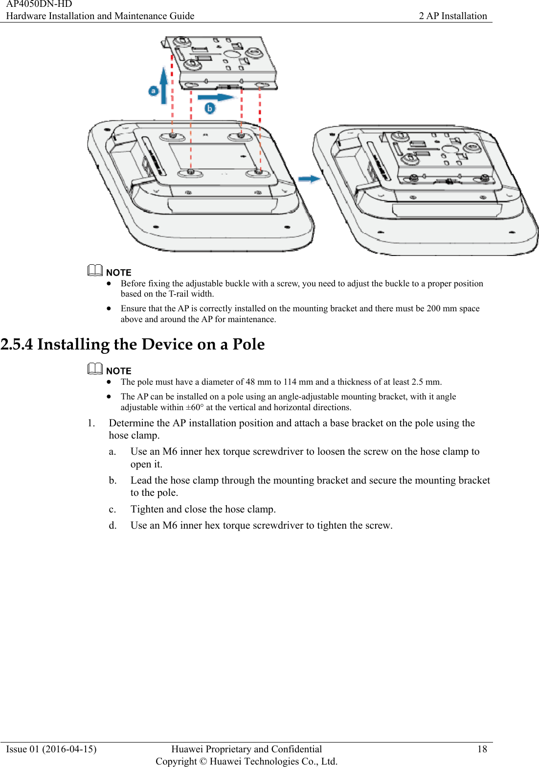
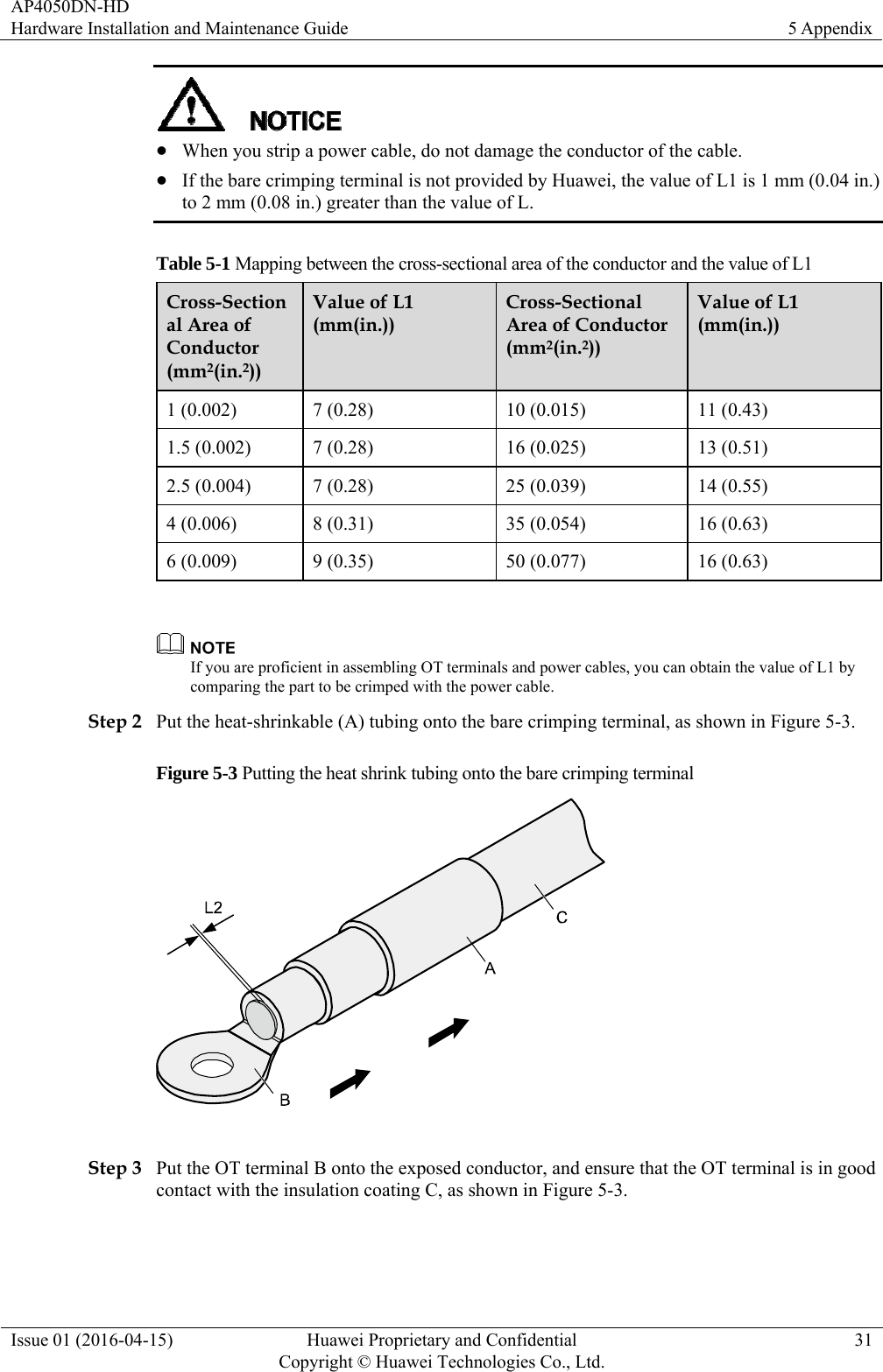
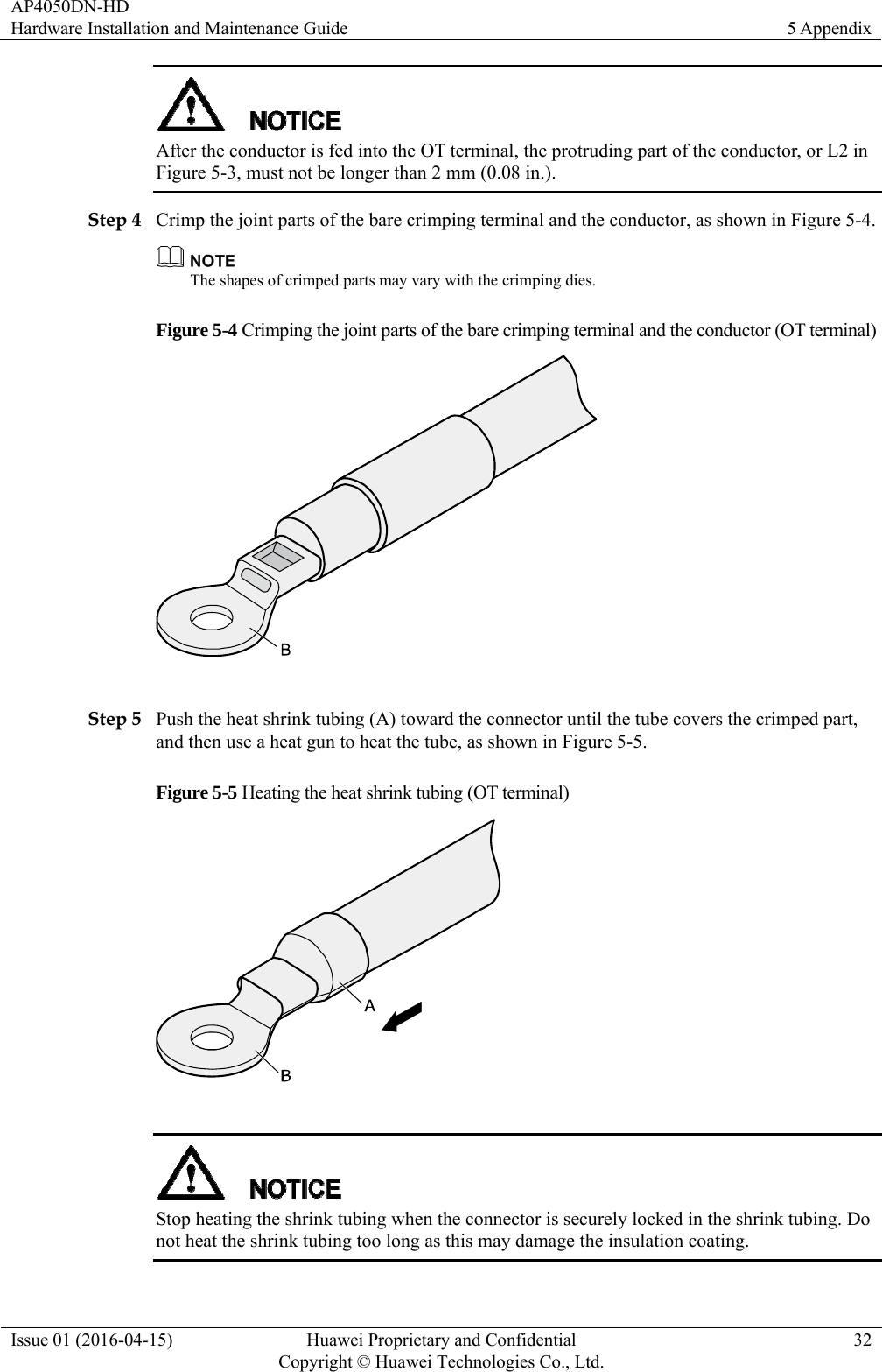
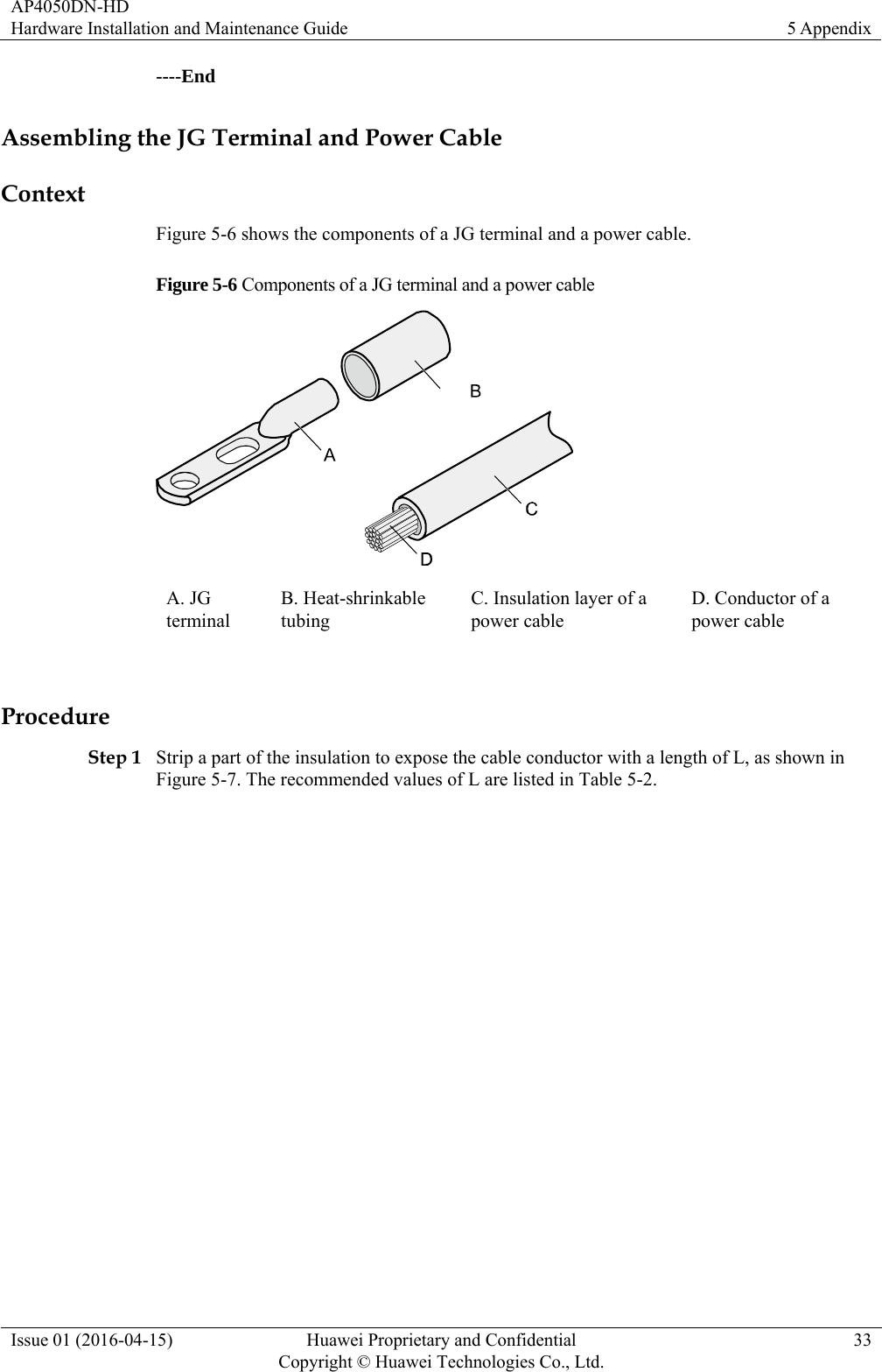
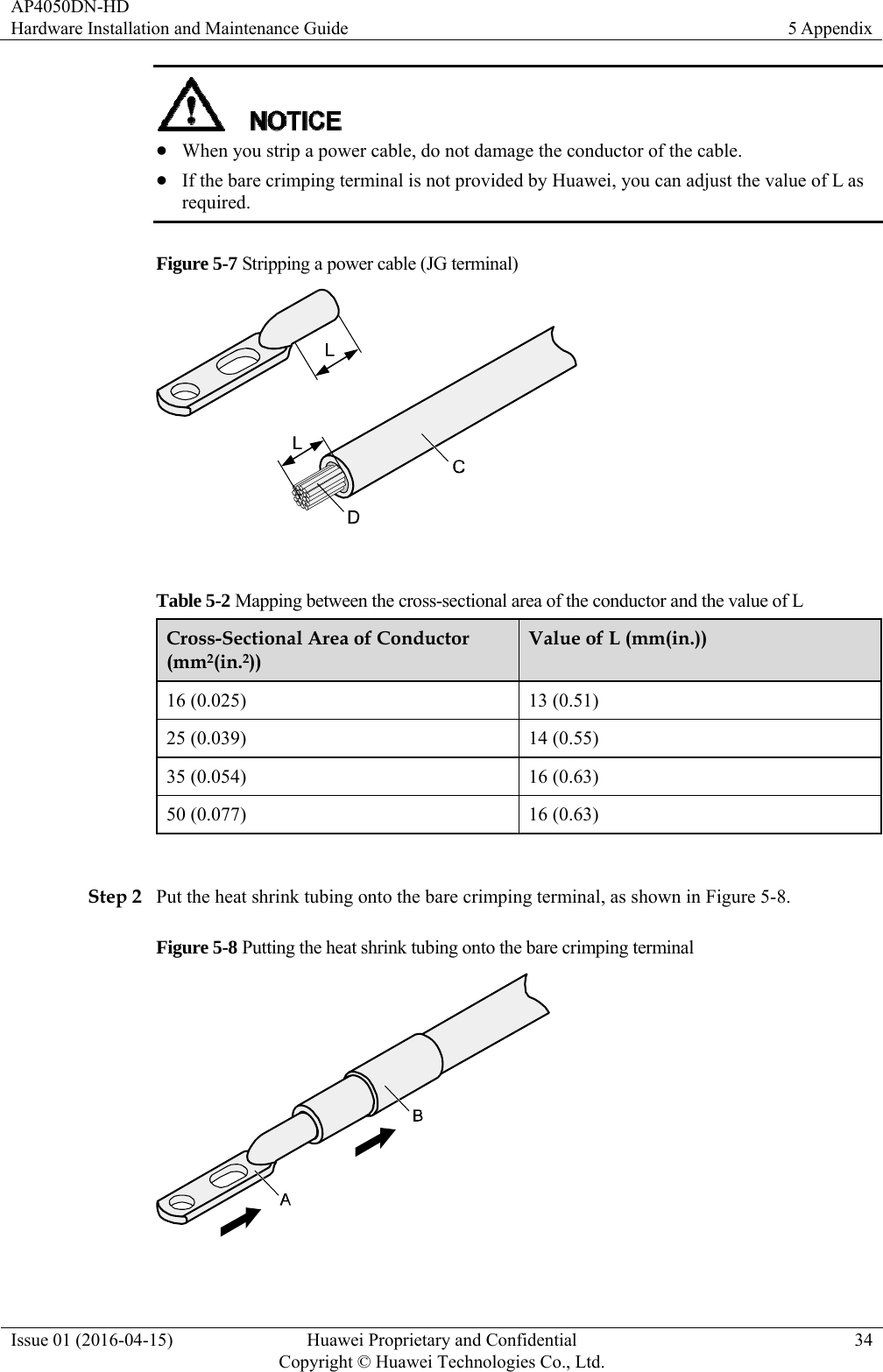
- 2. User ManualHardware Installation and Maintenance Guide
- 3. Users Manual
- 4. Hardware Installation and Maintenance Guide
User ManualHardware Installation and Maintenance Guide