Huawei Technologies AP6310SN-GN WLAN Access Point User Manual
Huawei Technologies Co.,Ltd WLAN Access Point
UserManual.wiki
>
Huawei Technologies
>
AP6310SN-GN User Manual
>
User Manual
Contents
1.
User Manual
2.
Compliance and Safety Manual
User Manual
Navigation menu
Upload a User Manual
Namespaces
Wiki Guide
HTML
PDF
Info
Views
User Manual
Discussion / Help
Navigation
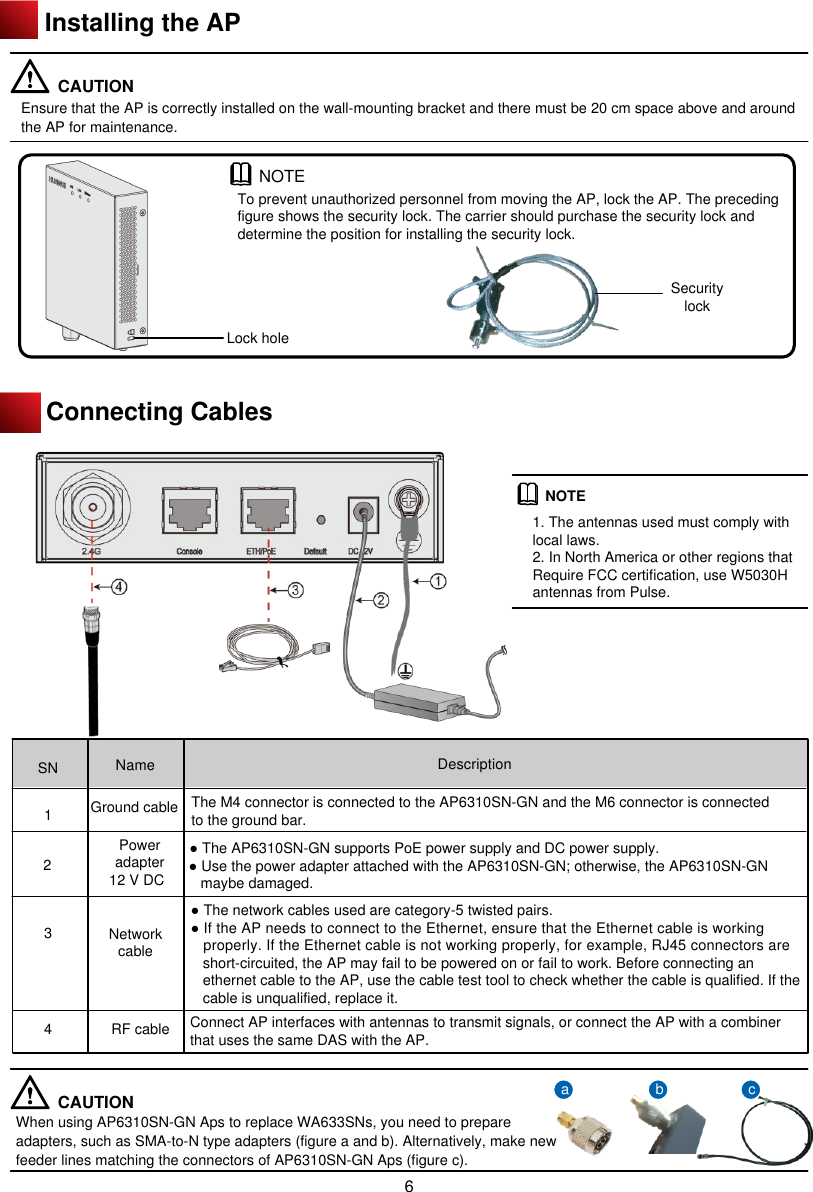
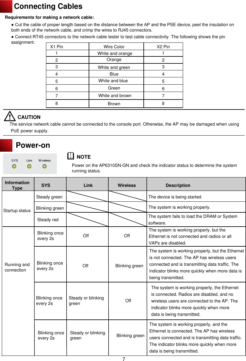
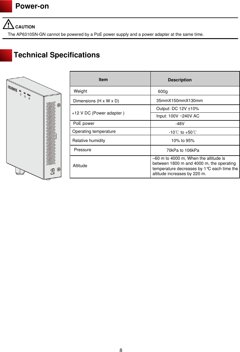
![AP Local Configuration ● Configuring the AP to go online in PPPoE mode 1. Use Telnet to log in to the AP from a PC. login: admin Password: // The default password is admin. ~ # 2. Configure the AP to go online in PPPoE mode. ~ # cli Enterprise AP# configure interface ethernet // Enter the AP interface view. Enter Ethernet configuration commands, one per line. Enterprise AP (if-ethernet) # ip mode pppoe // Set the mode in which the AP goes online. Please reboot the AP, configuration will take effect Enterprise AP (if-ethernet) # 3. Configure a user name and password for going online in PPPoE mode. By default, the user name and password are both wlan@huawei and the password type is simple. Enterprise AP(if-ethernet) # user admin password simple admin //Set the user name and password to admin. 4. Restart the AP to make the configuration take effect. ~ # reboot NOTE ● After the configuration is complete, run the reboot command to restart the AP. ● After the configuration is complete, run the show sysinfo command to check the configuration. Enterprise AP(if-ethernet) # show sysinfo ap_ipmode=pppoe ap_ipaddr= ap_ipversion=4 ap_netmask= ap_gateway= ac_ip1= ac_ip2= ac_ip3= ac_ip4= pppoe_username=wlan@huawei pppoe_pwd_type=simple pppoe_password=wlan@huawei NOTE By default, the PVID of a wired-side interface is 0, and no VLAN is configured on the interface. 1. Use Telnet to log in to the AP from a PC. login: admin Password: //The default password is admin. ~ # 2. Configure VLANs and PVID on the wired interface. ~ # cli Enterprise AP# configure interface ethernet // Enter the AP interface view. Enter Ethernet configuration commands, one per line. Enterprise AP (if-ethernet) # ether-port 0 [1-4095] [tag/untag] // Configure the VLANs allowed by the wired interface. Enterprise AP (if-ethernet) # ether-port 0 pvid [1-4095] //Configure the PVID of the wired interface. NOTE The configuration takes effect immediately, and you do not need to restart the AP.2. Configuring VLANs on Wired Interfaces of an AP This section describes how to configure VLANs on wired interfaces of an AP. ● Introduction to the Wired Interfaces A wired interface on an AP is connected to an AC or a switch. When the AP assigns service VLANs to packets, you can configure VLANs on wired interfaces of the AP. ●Configuring VLANs on a Wired Interface 13](https://usermanual.wiki/Huawei-Technologies/AP6310SN-GN.User-Manual/User-Guide-1778117-Page-14.png)