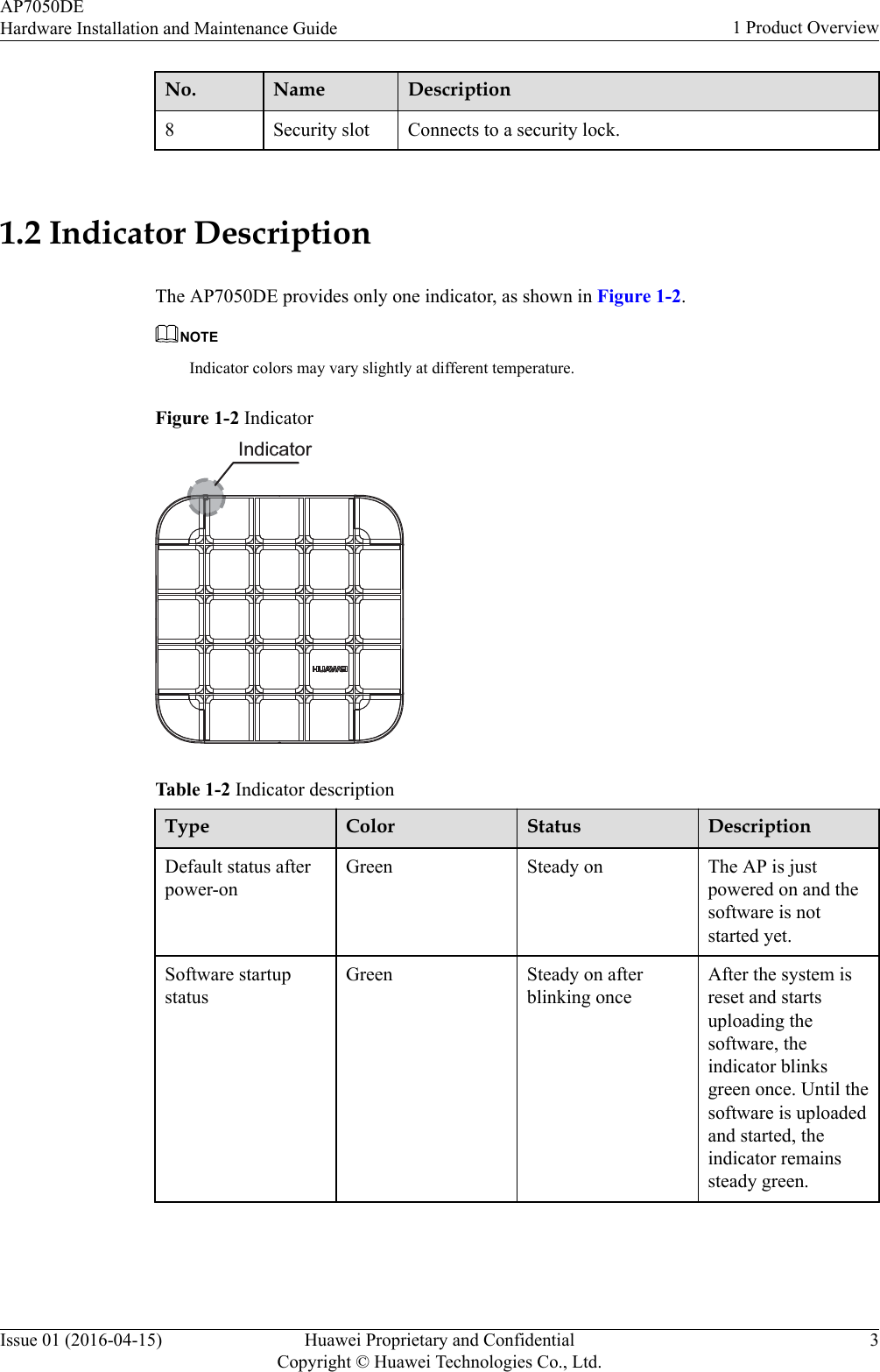
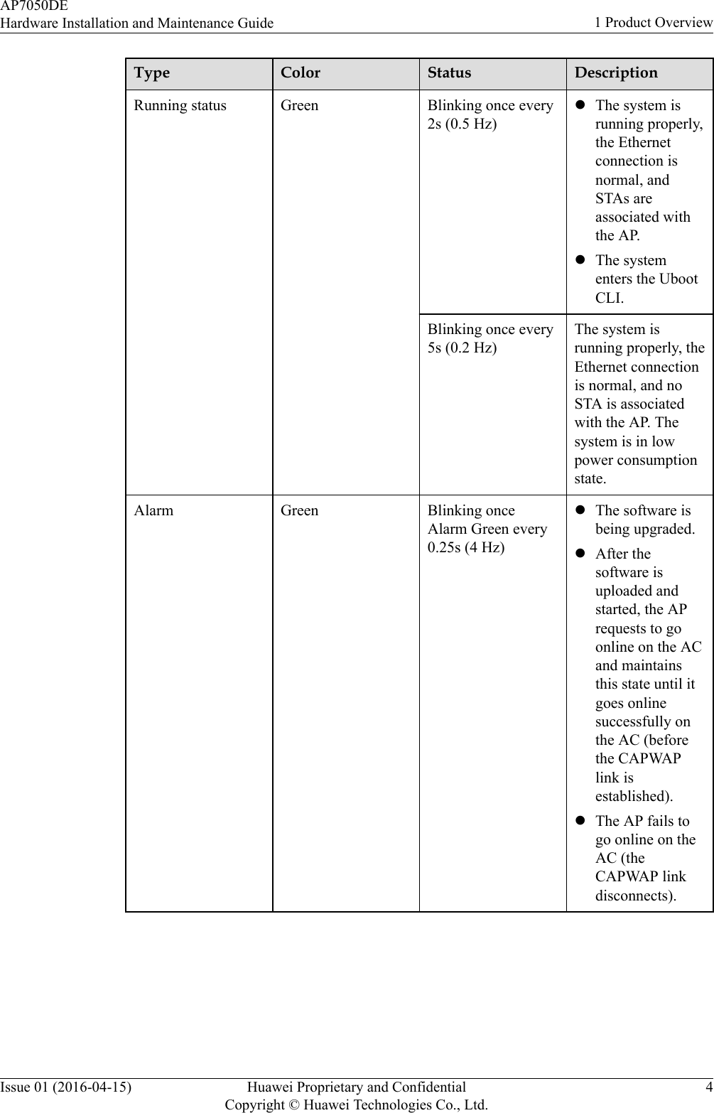
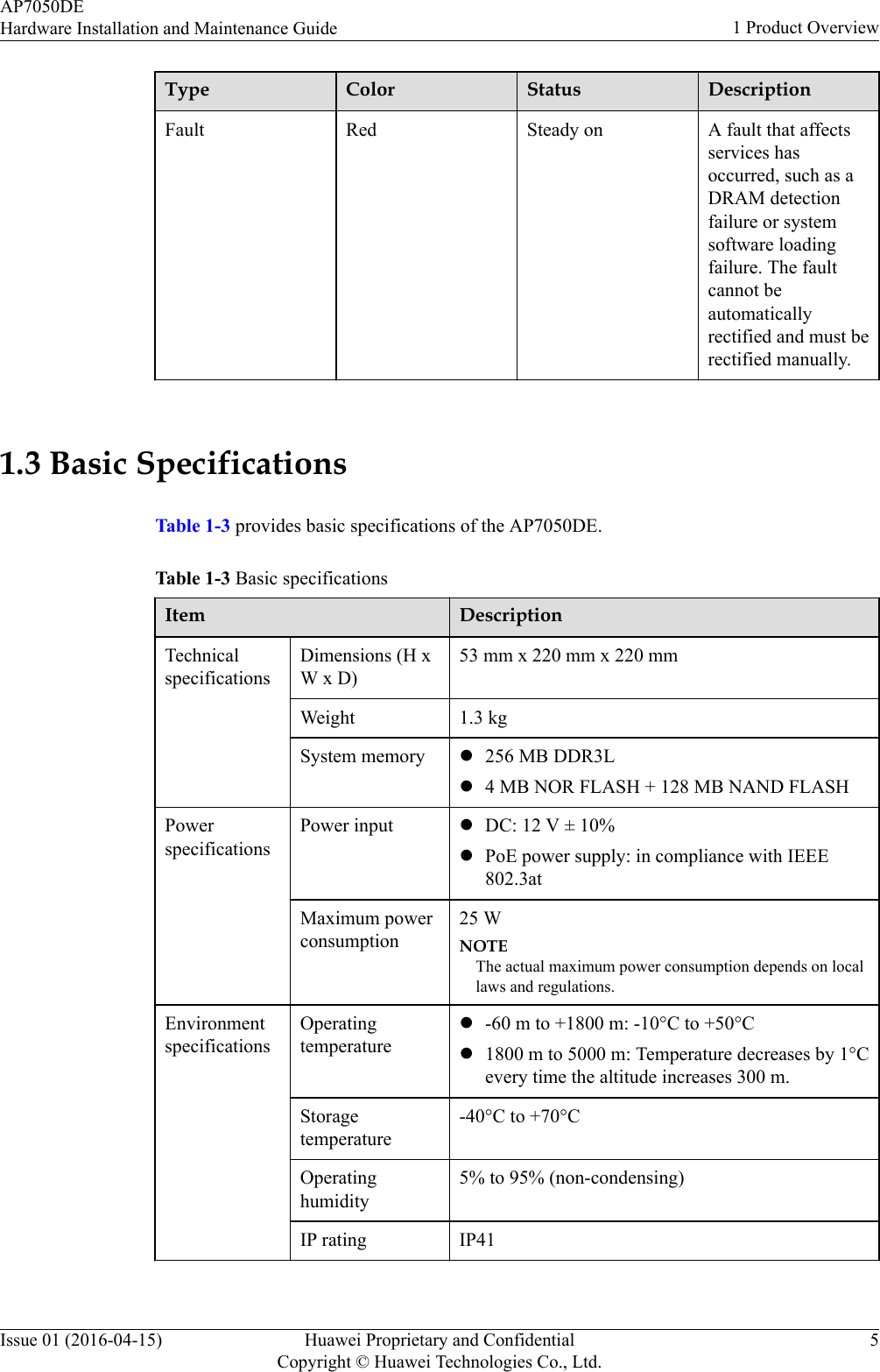
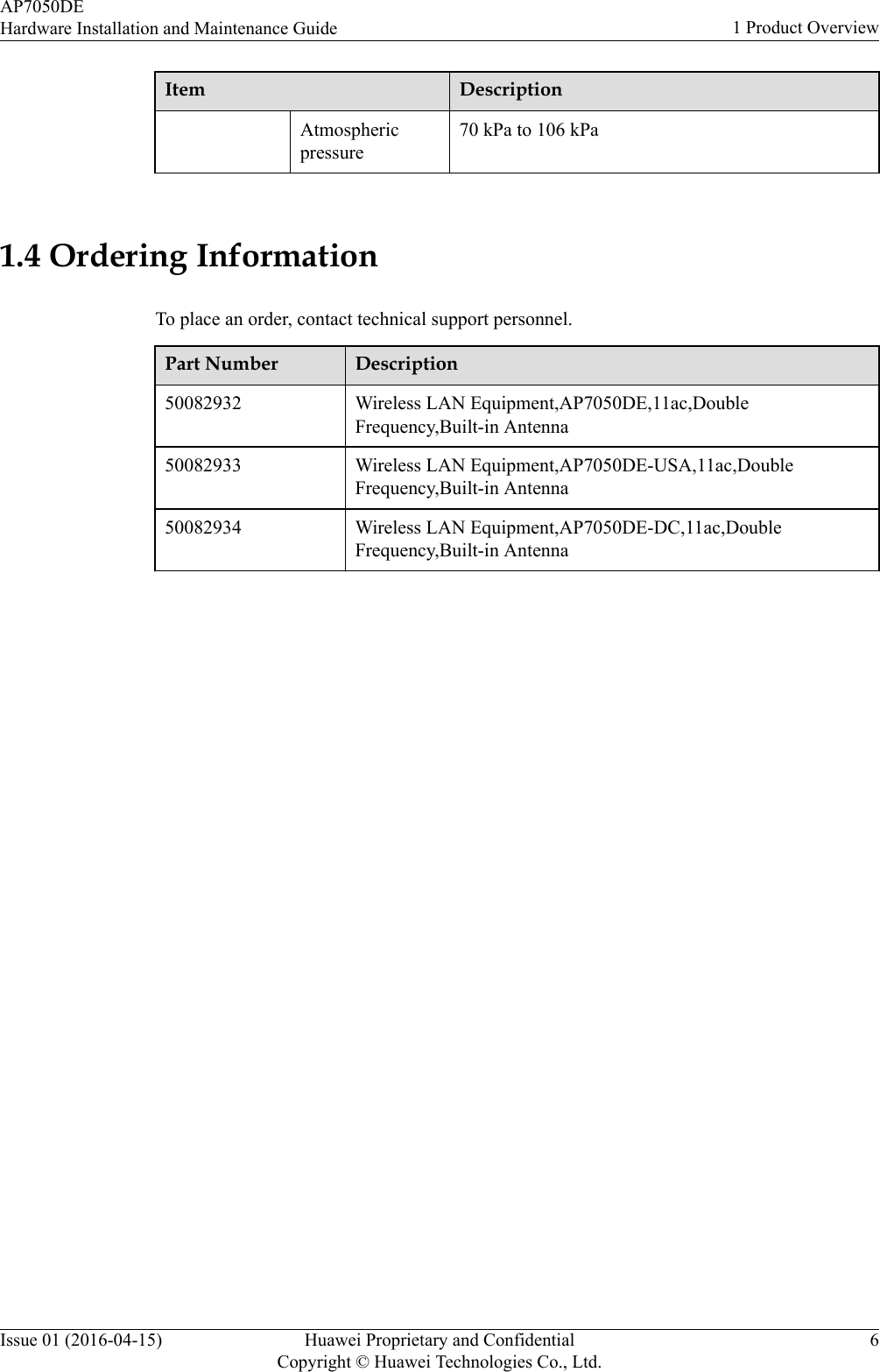
Huawei Technologies AP7050DE Wireless LAN Access Point User Manual Hardware Installation and Maintenance Guide
Huawei Technologies Co.,Ltd Wireless LAN Access Point Hardware Installation and Maintenance Guide
Contents
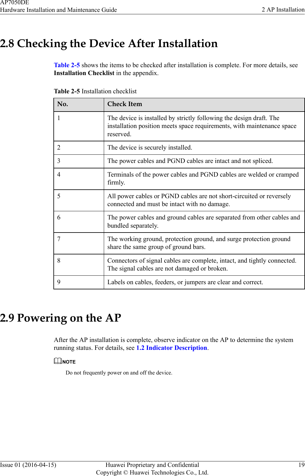
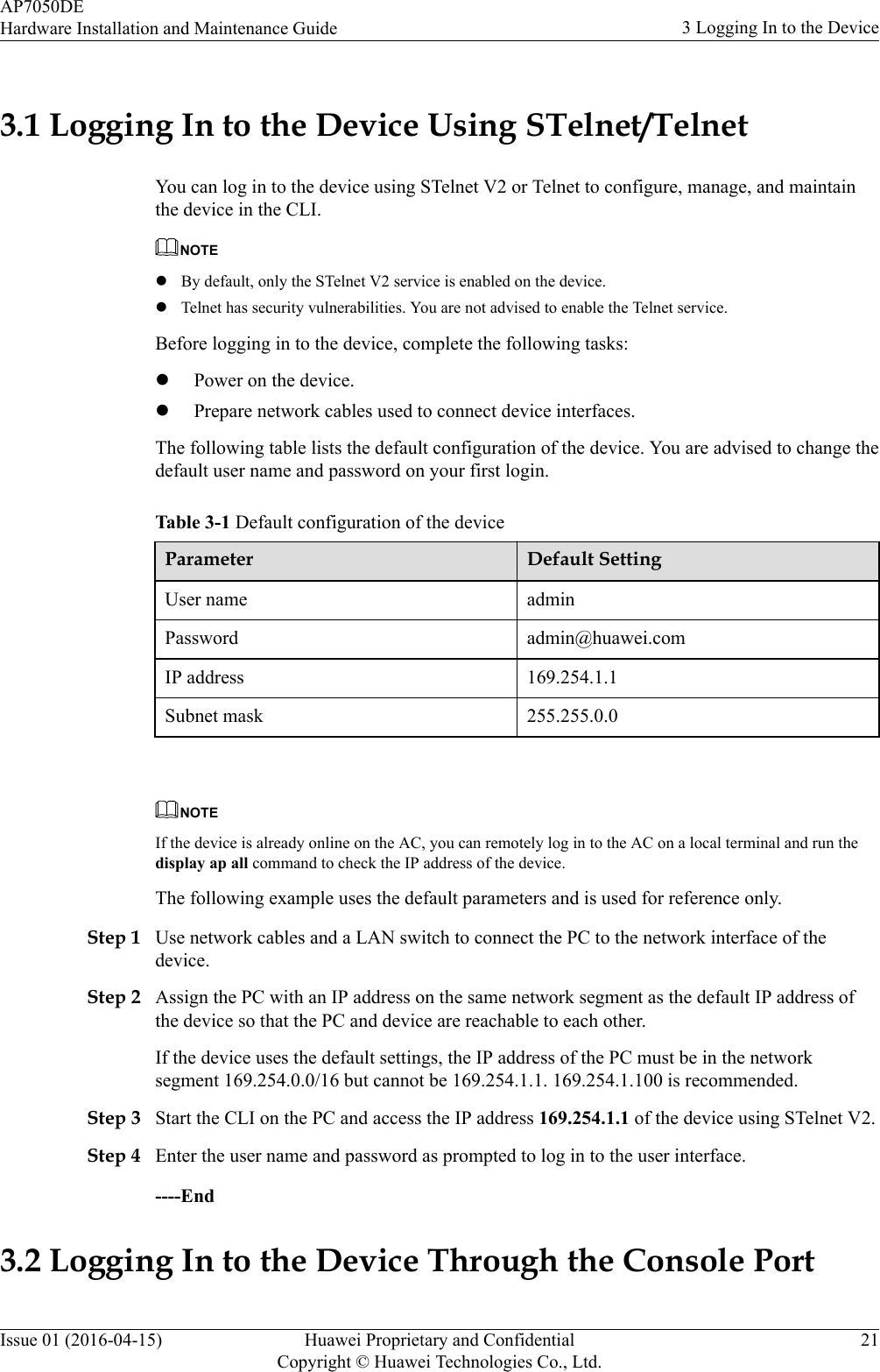
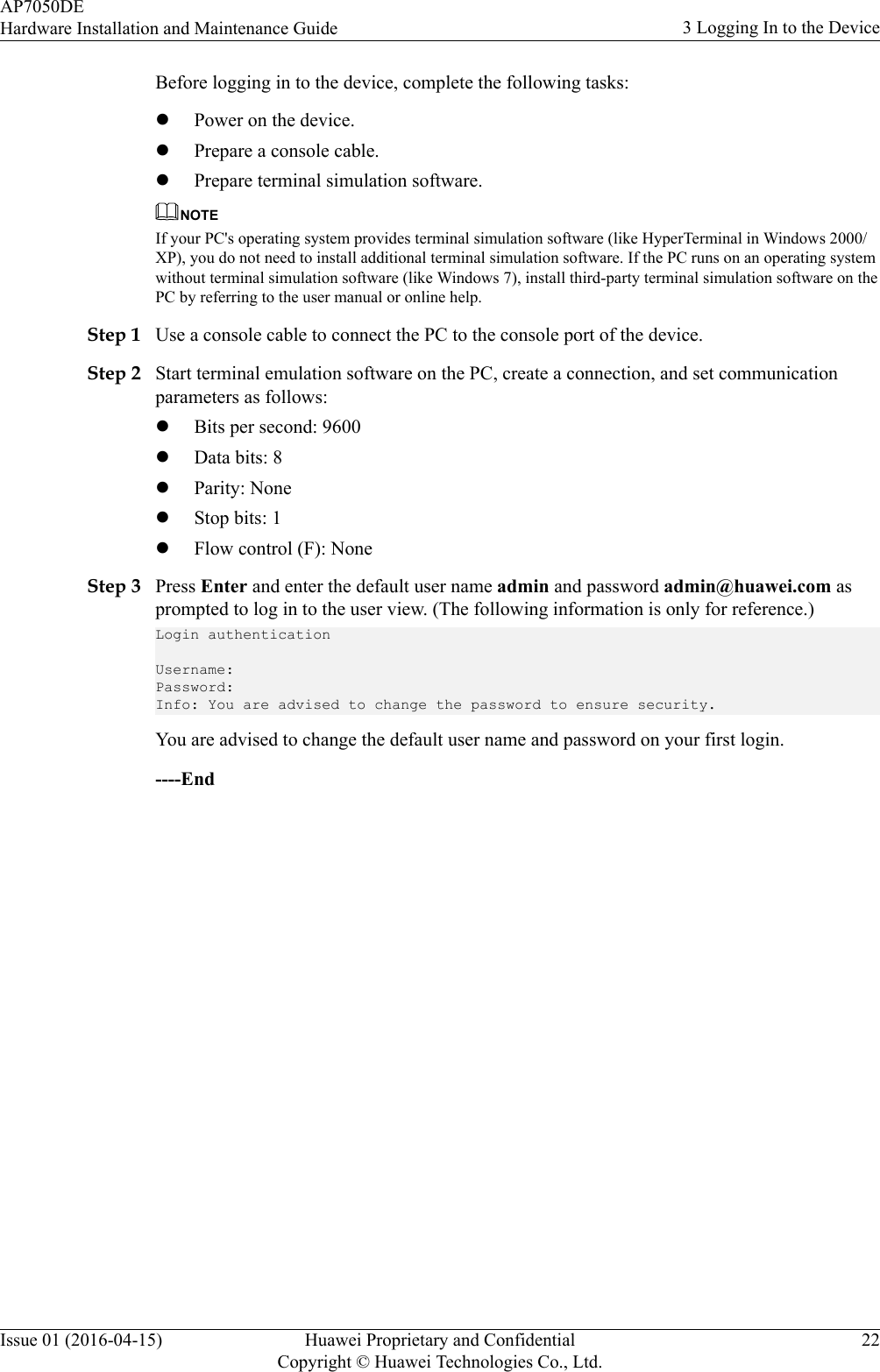
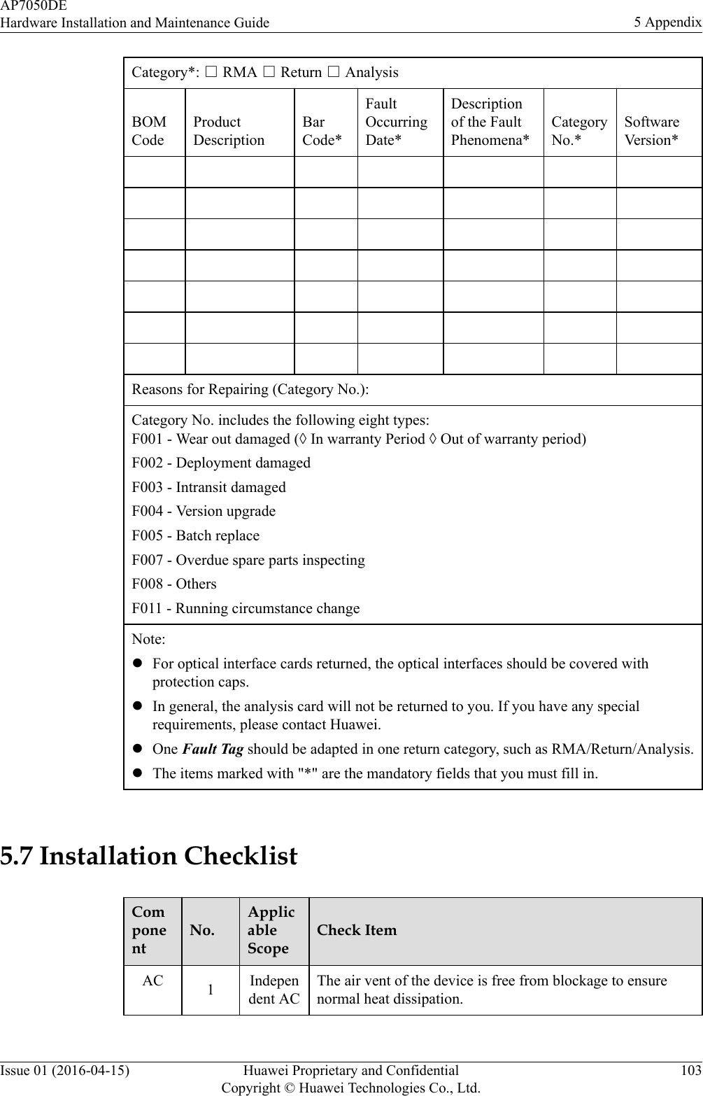
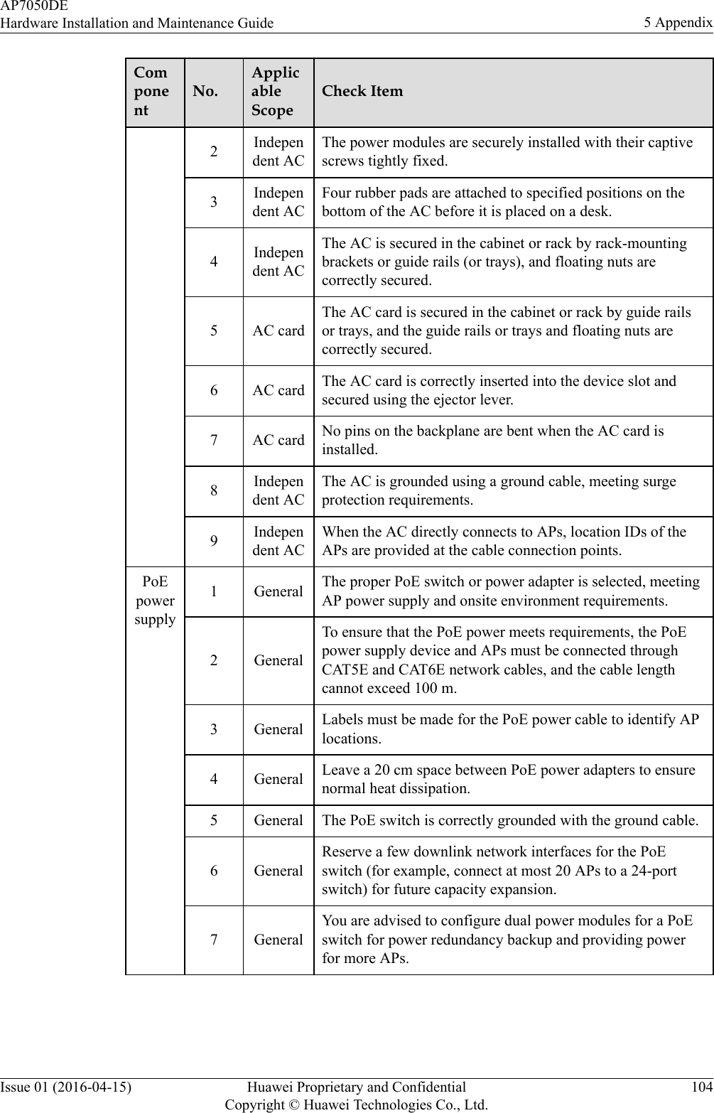
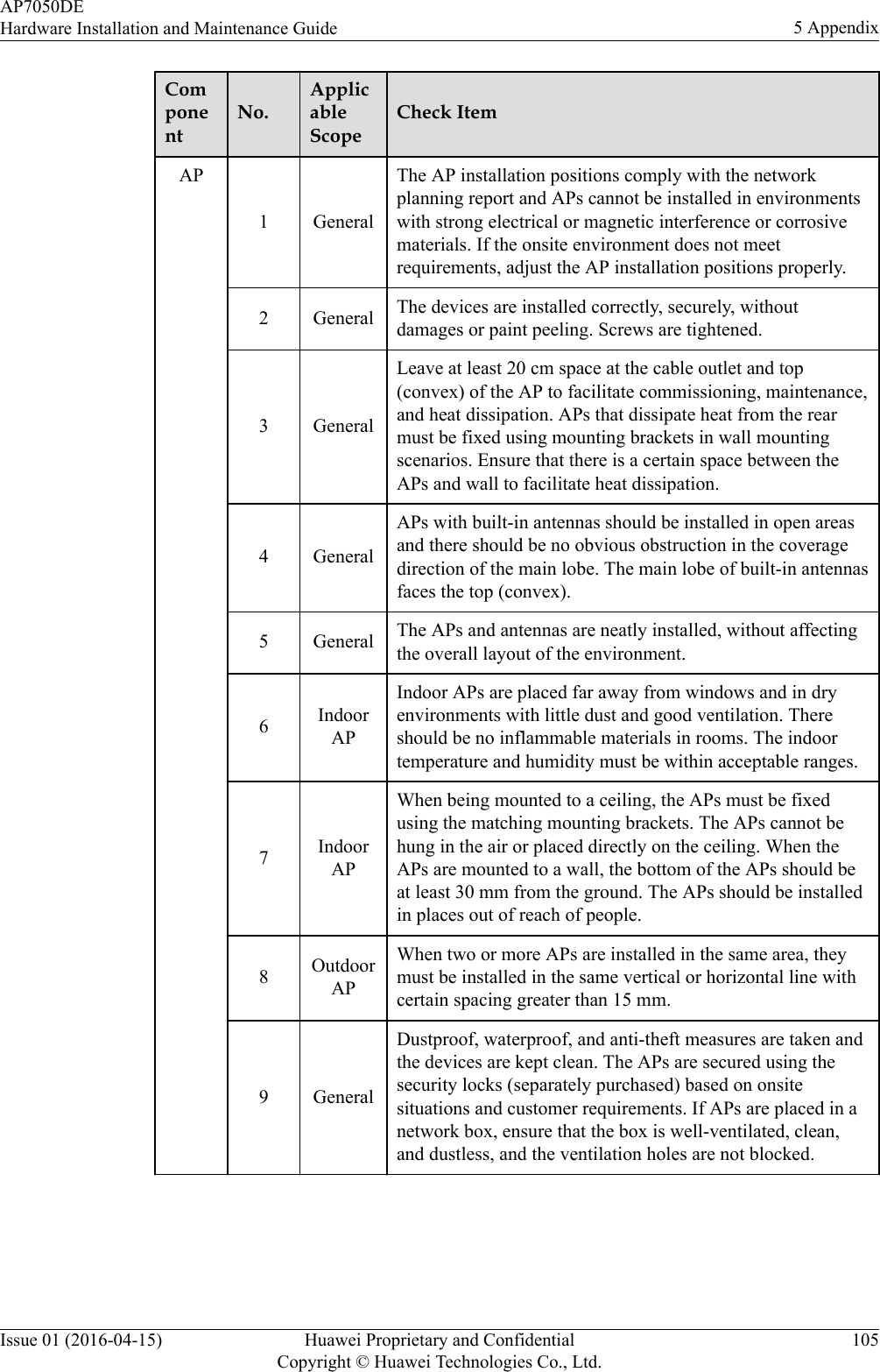
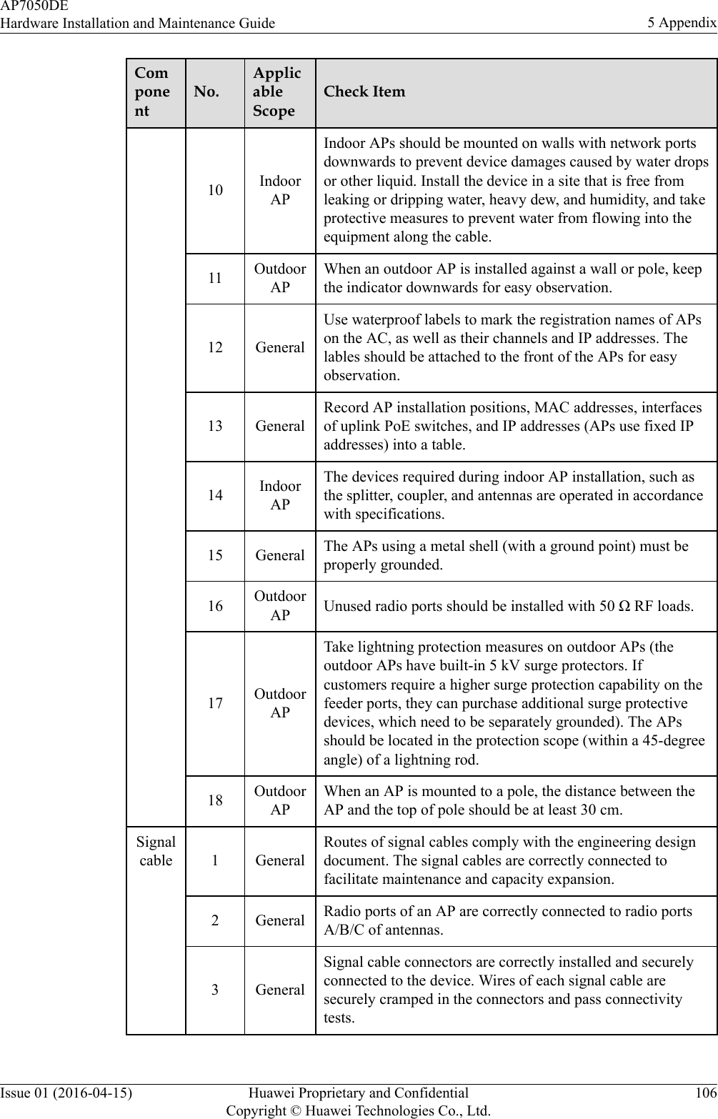
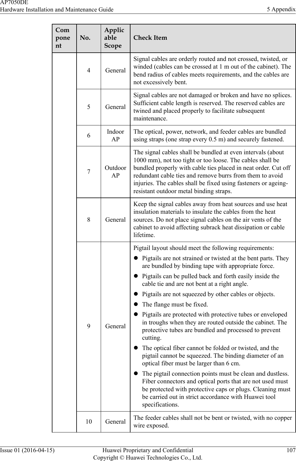
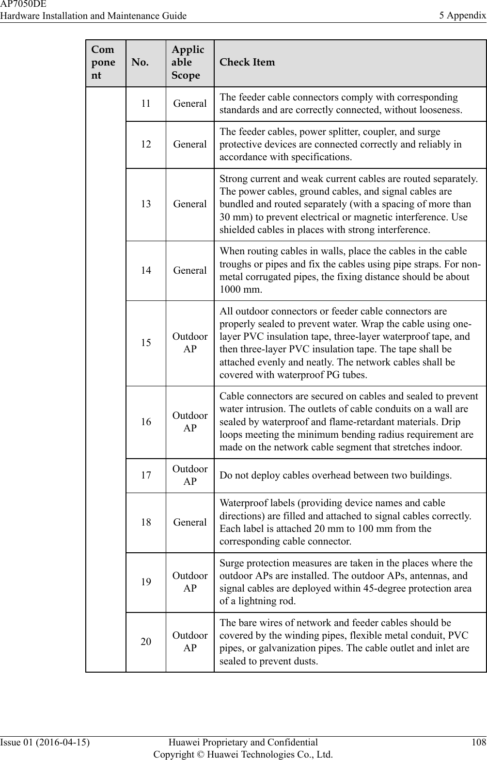
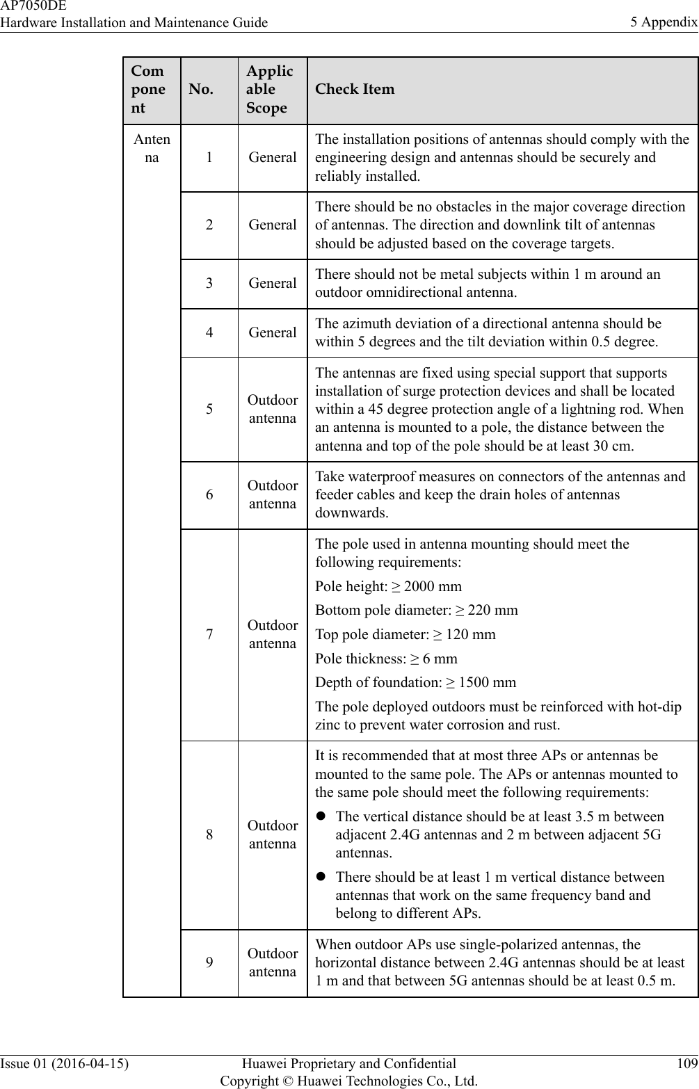
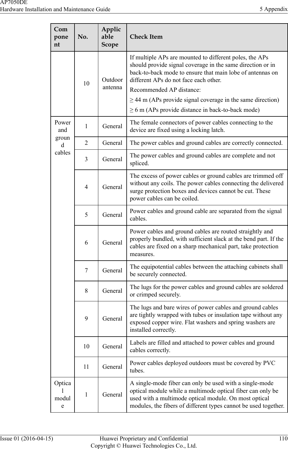
- 1. User ManualHardware Installation and Maintenance Guide
- 2. User Manual
- 3. User Manual Revised
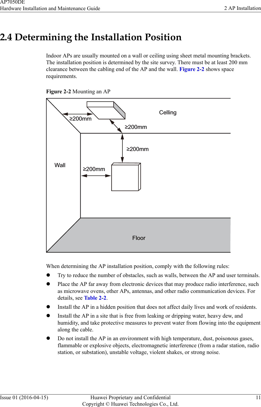
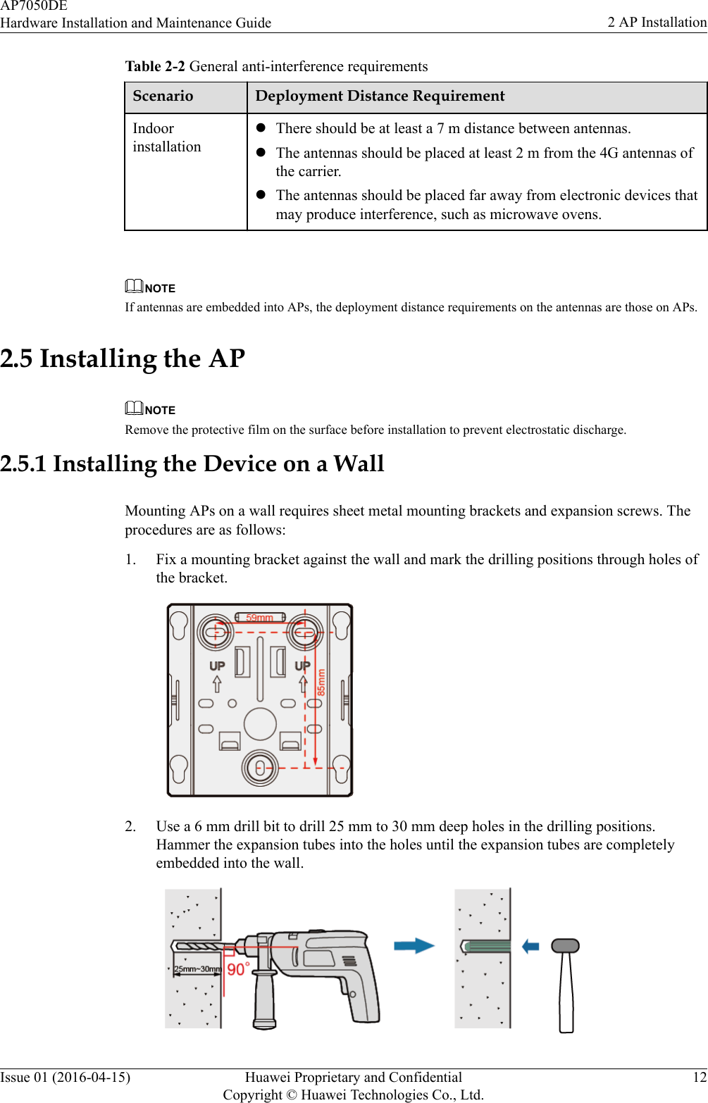
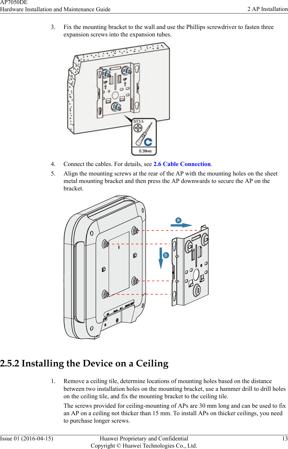
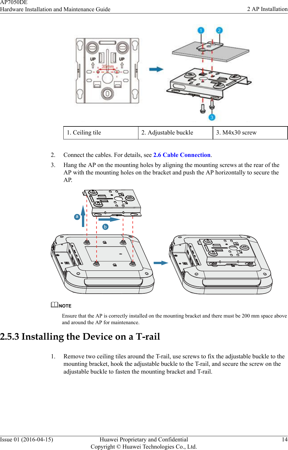
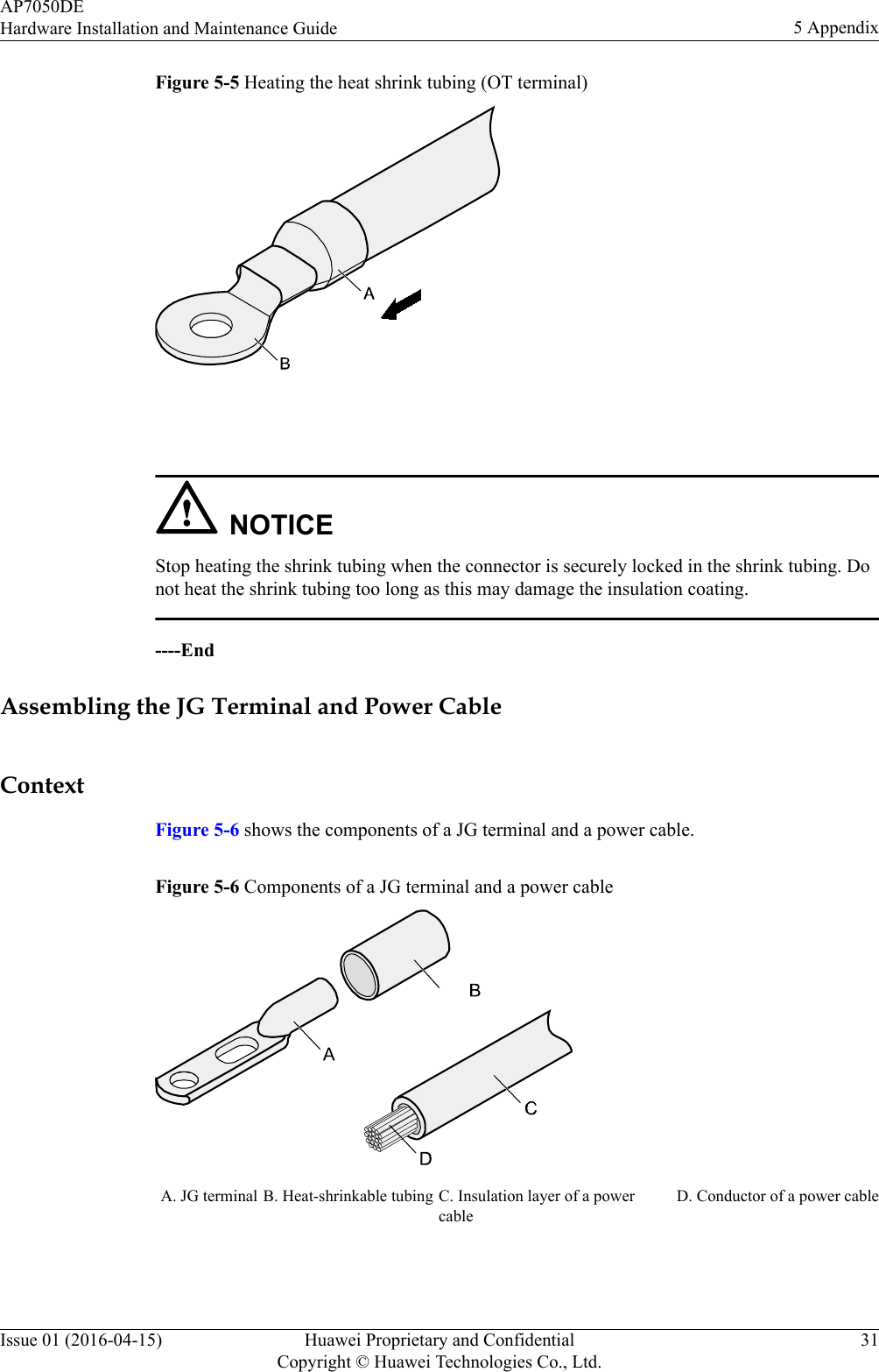
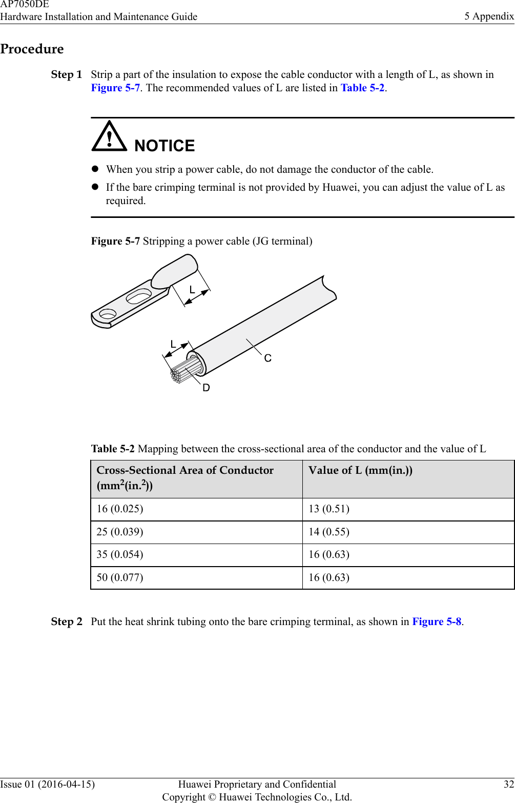
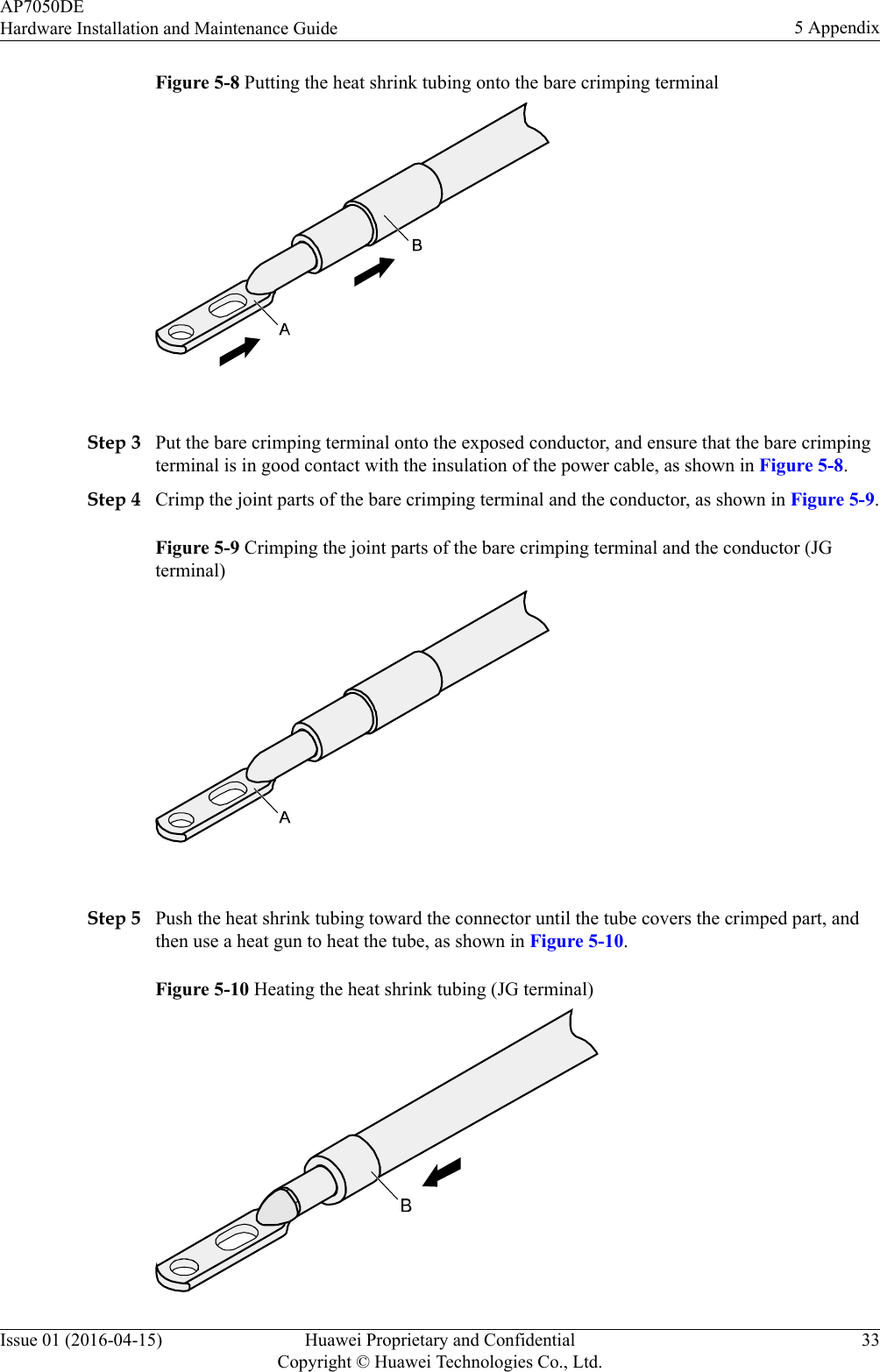
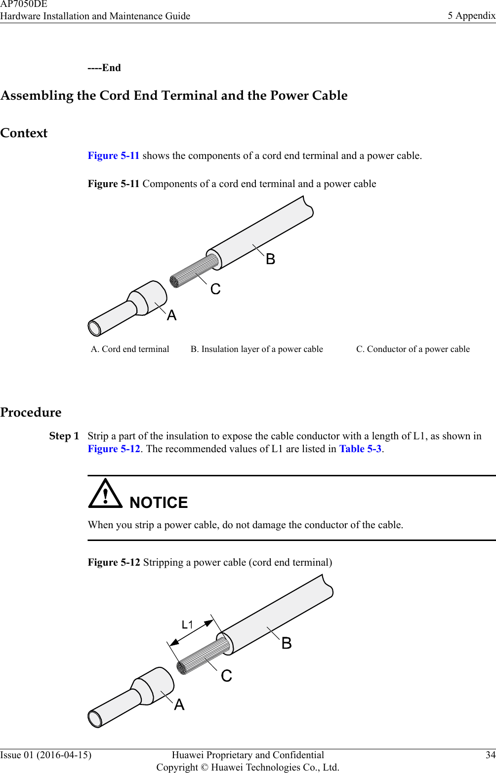
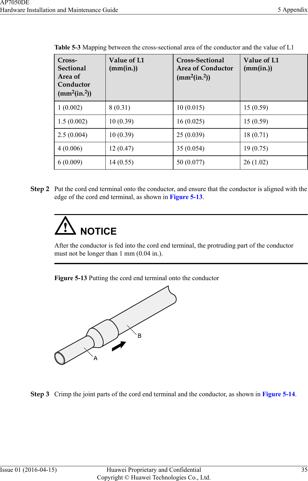
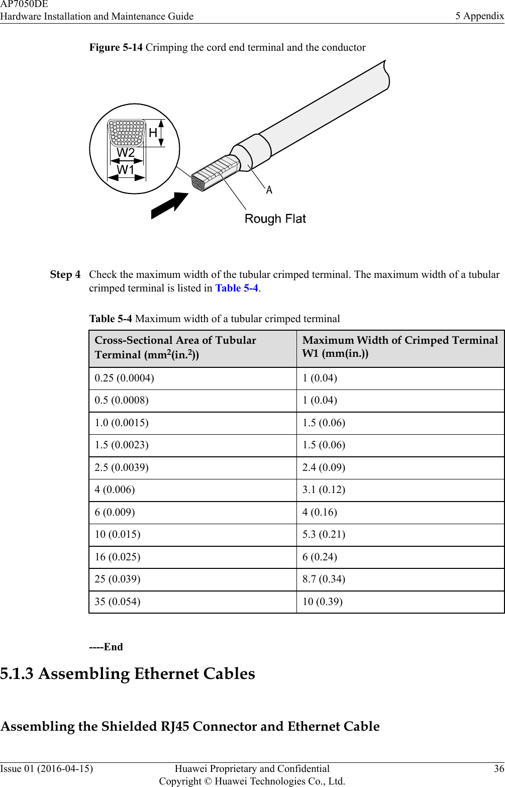
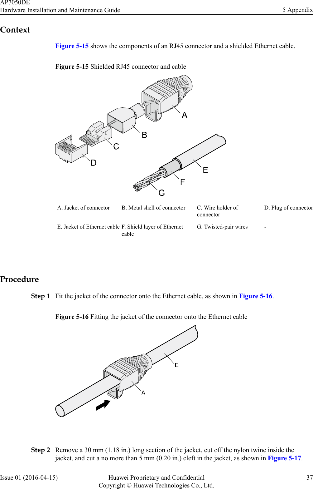
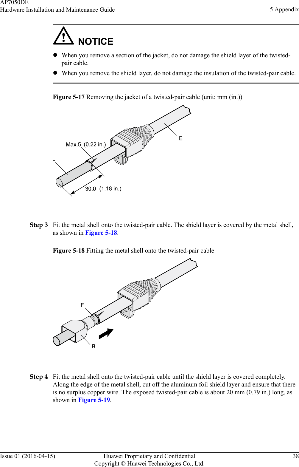
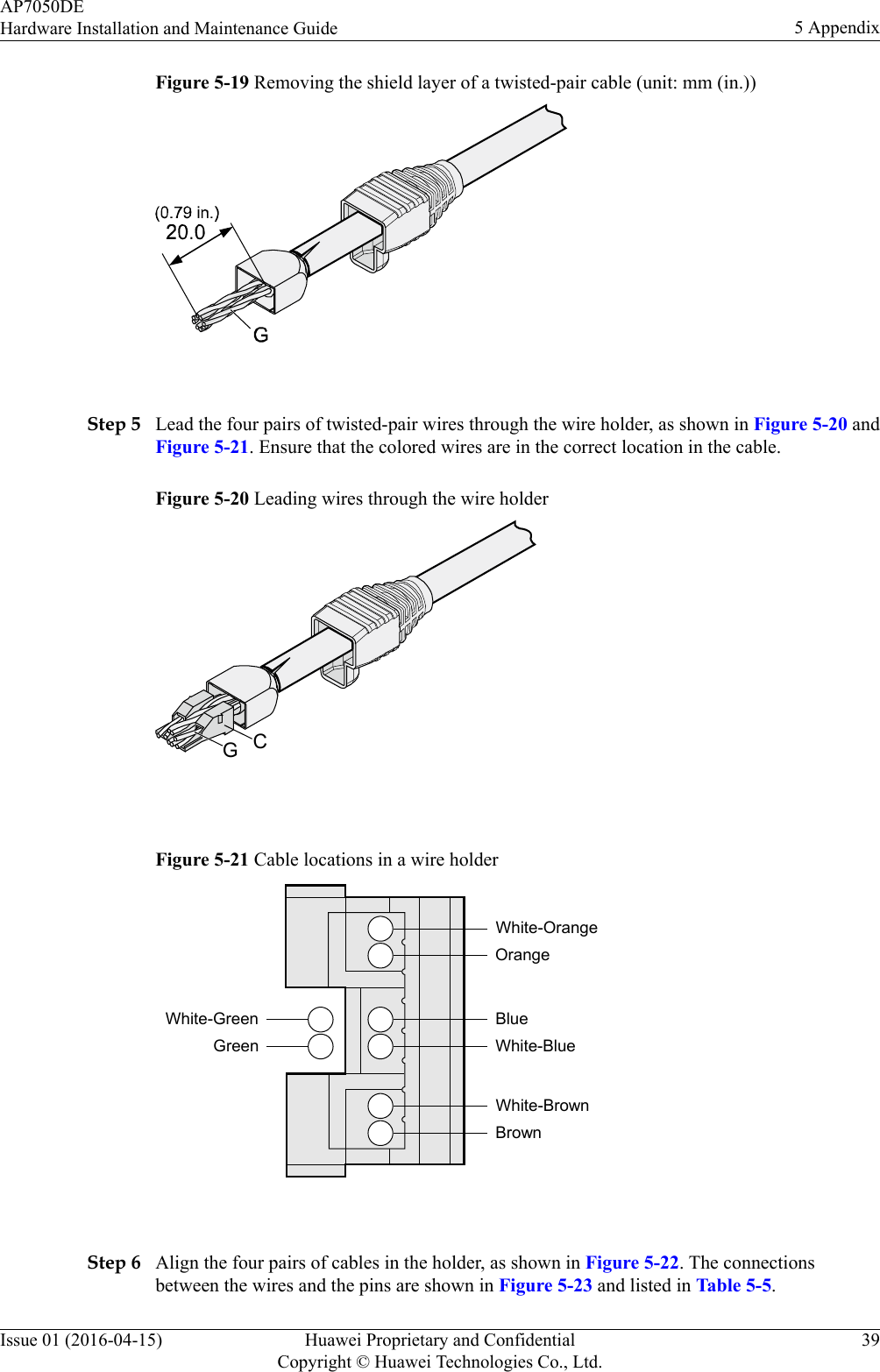
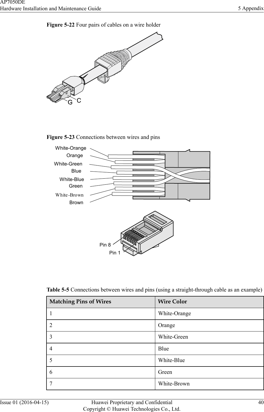
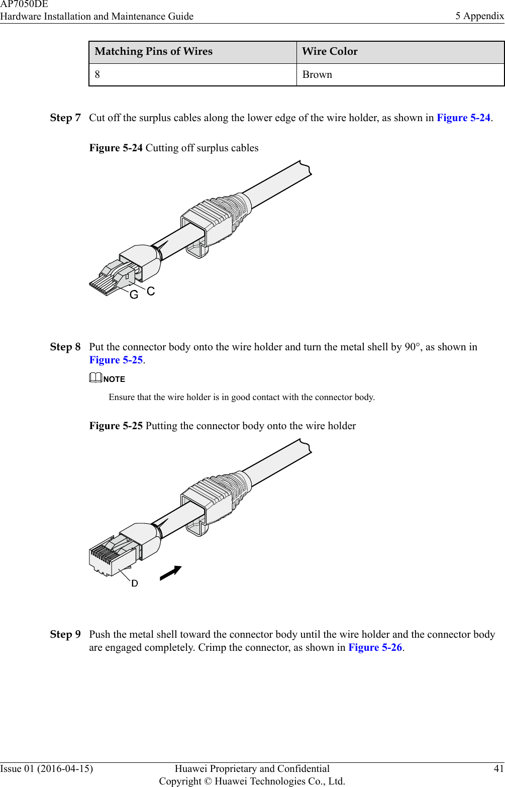
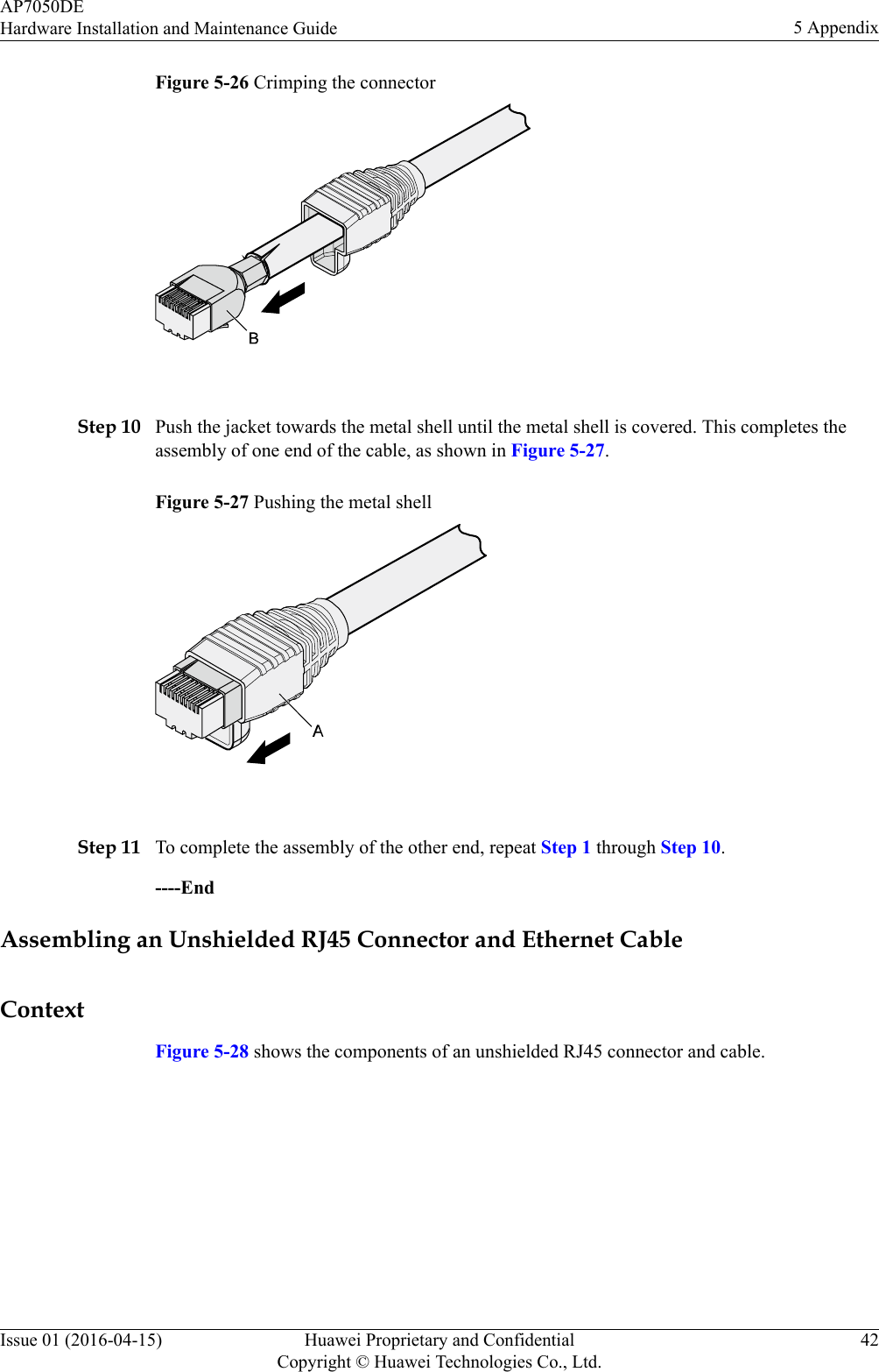
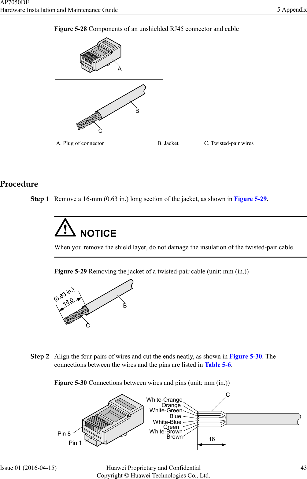
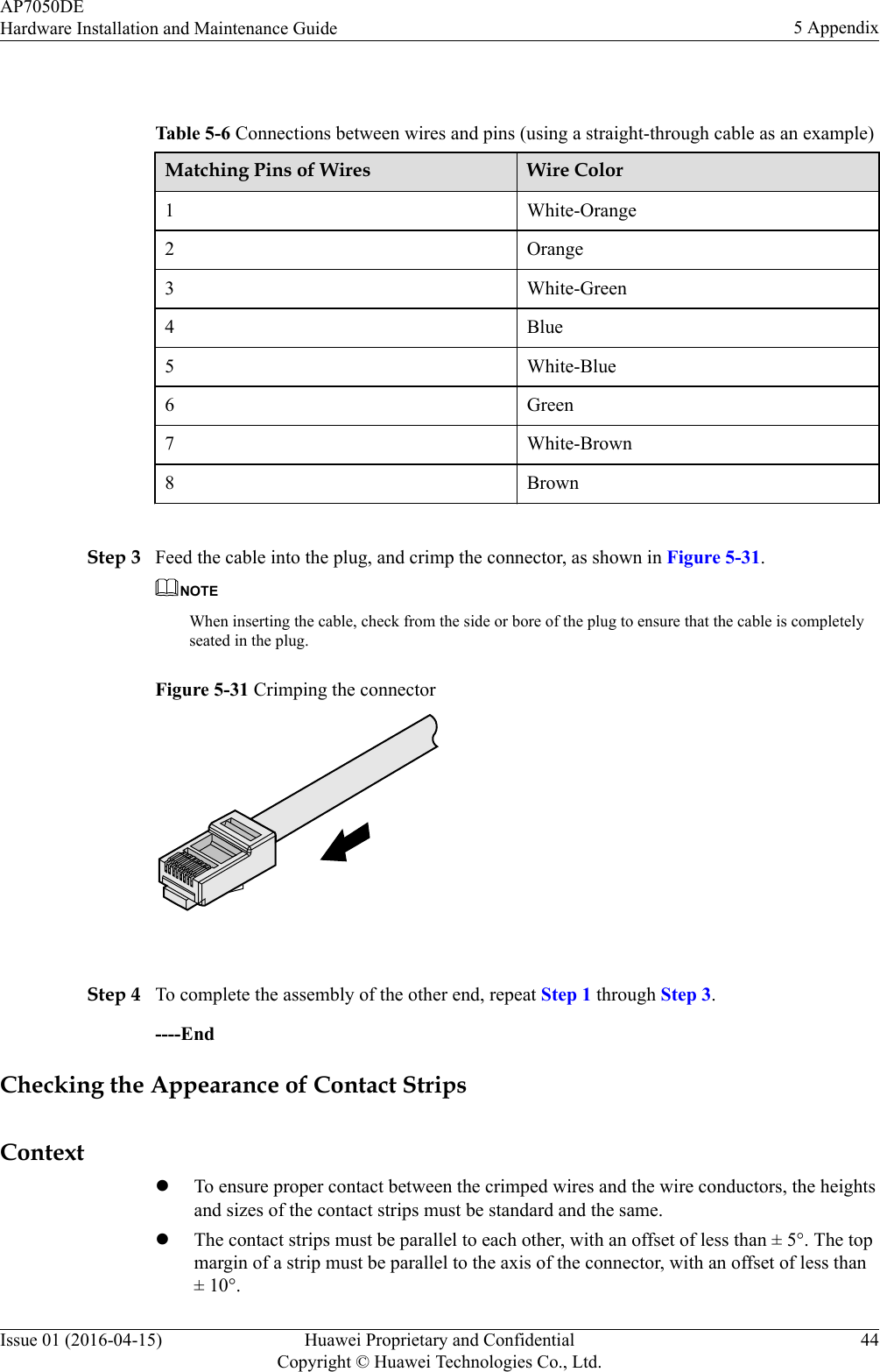
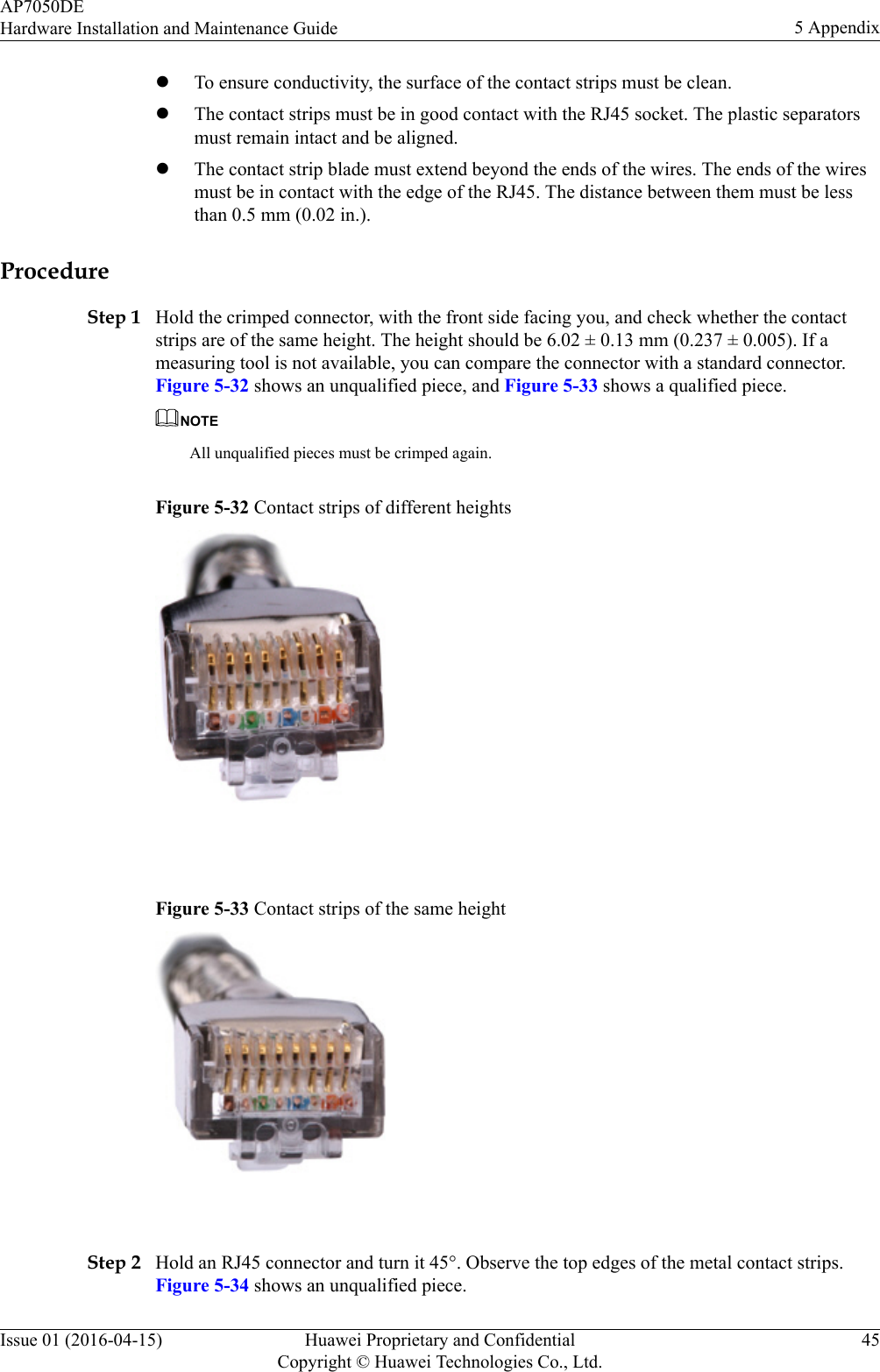
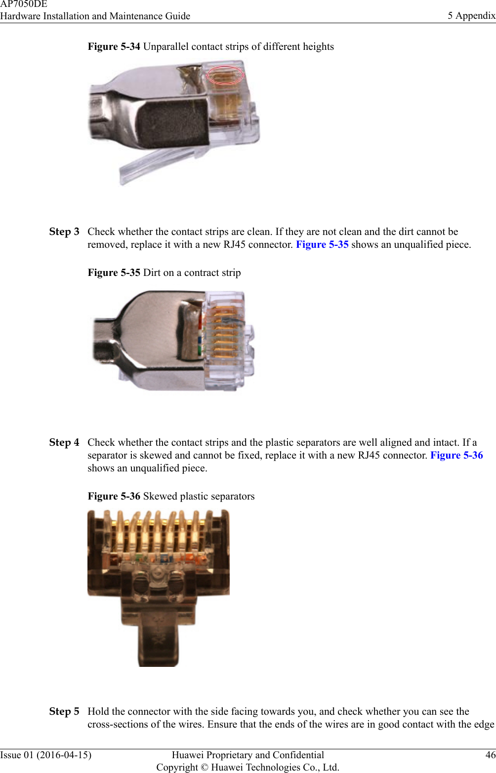
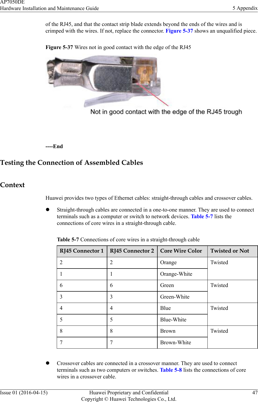
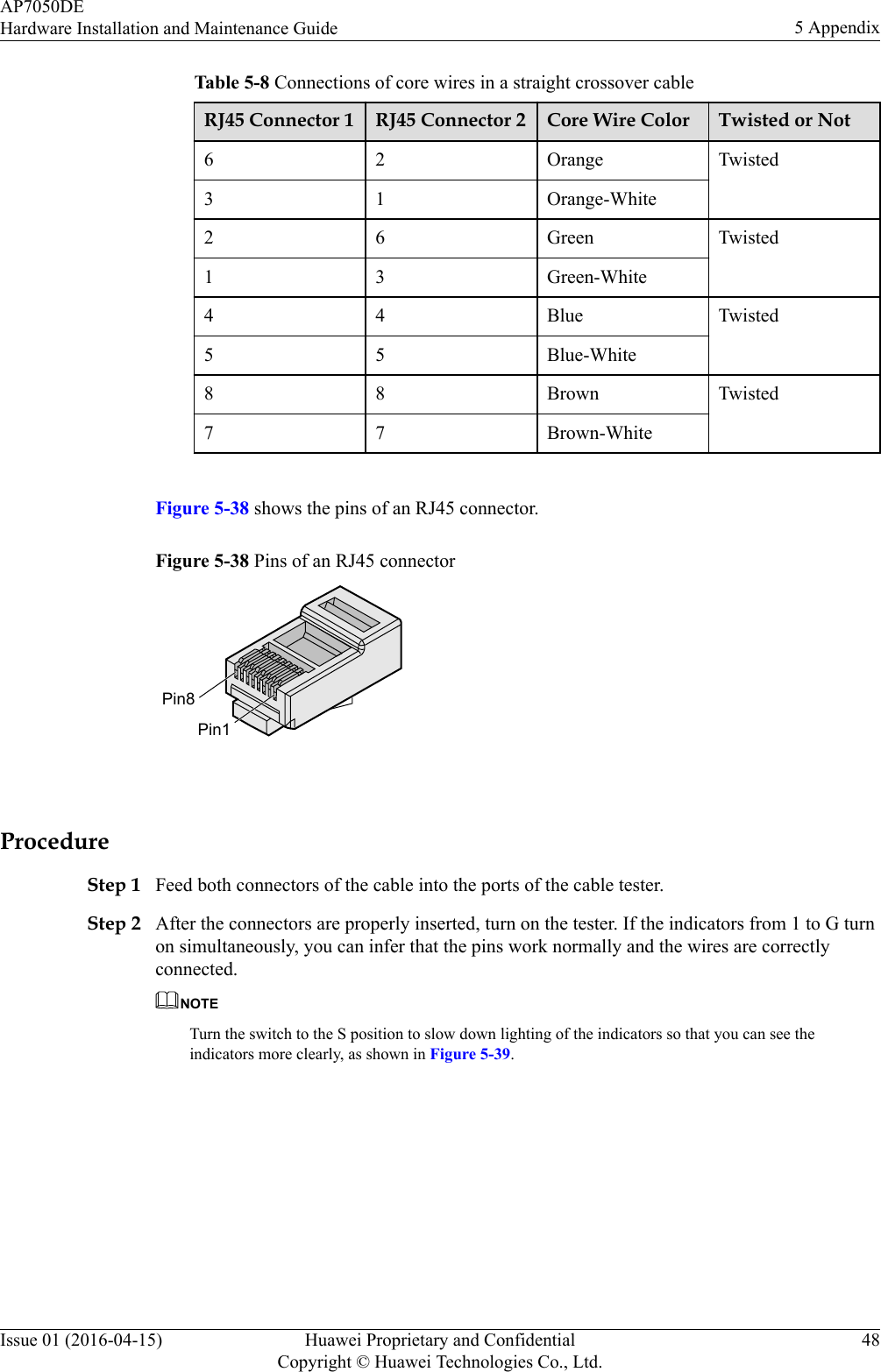
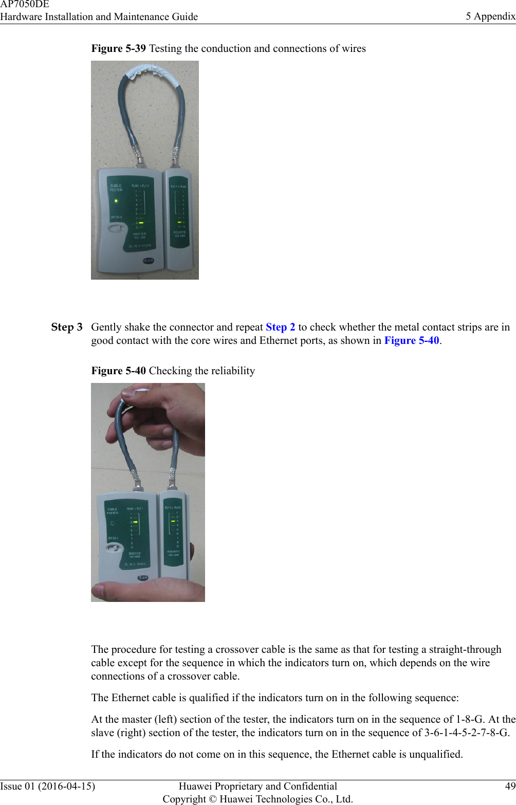
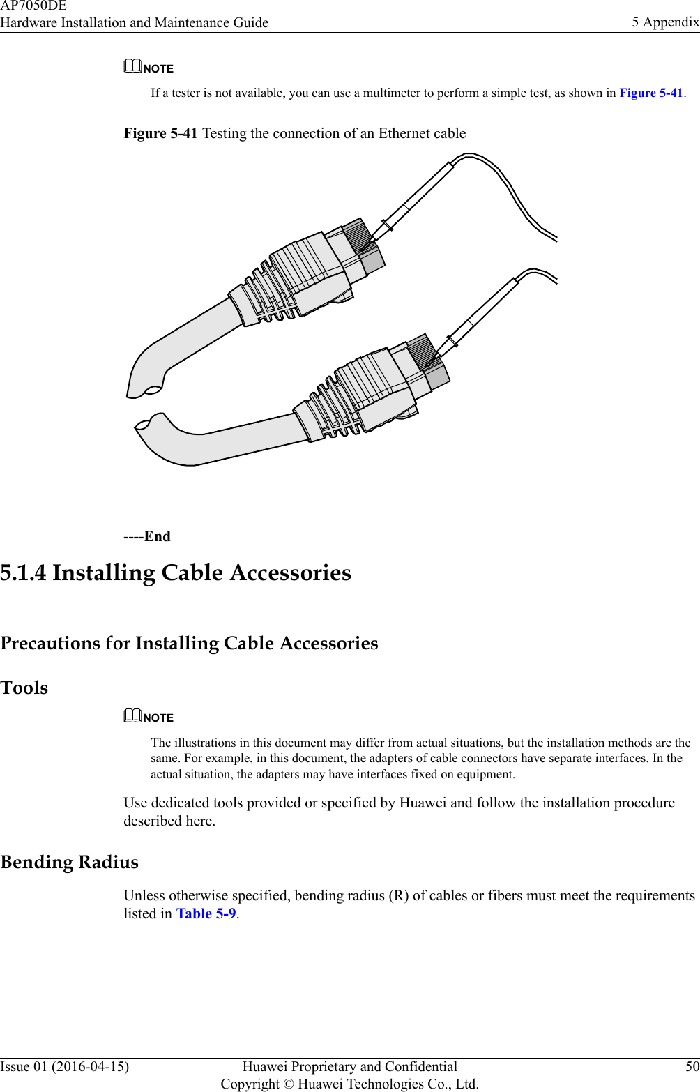
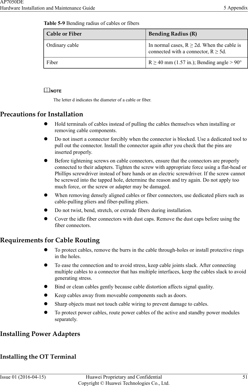
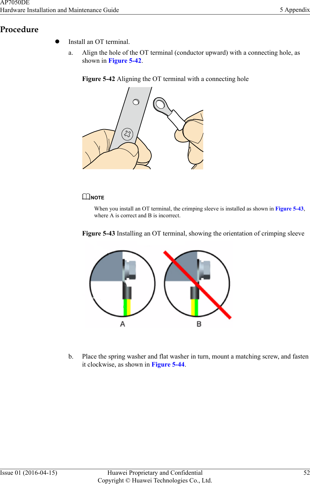
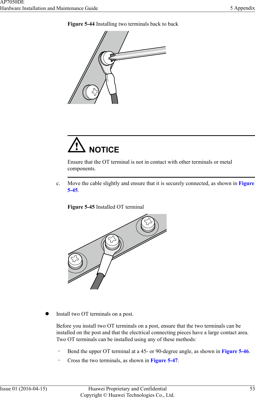
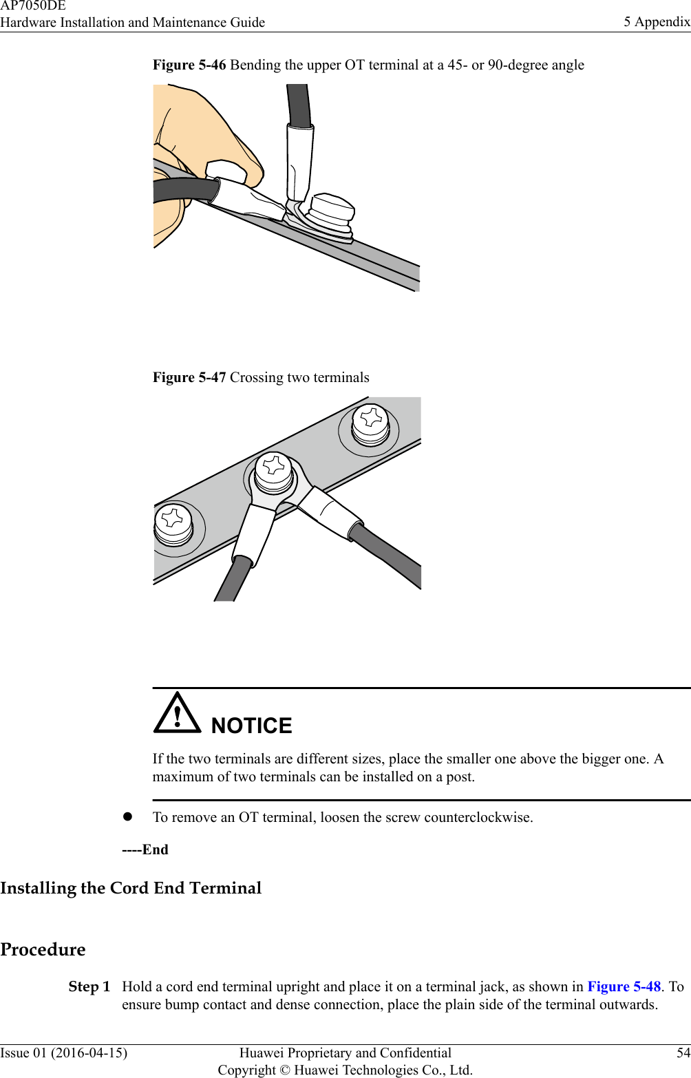
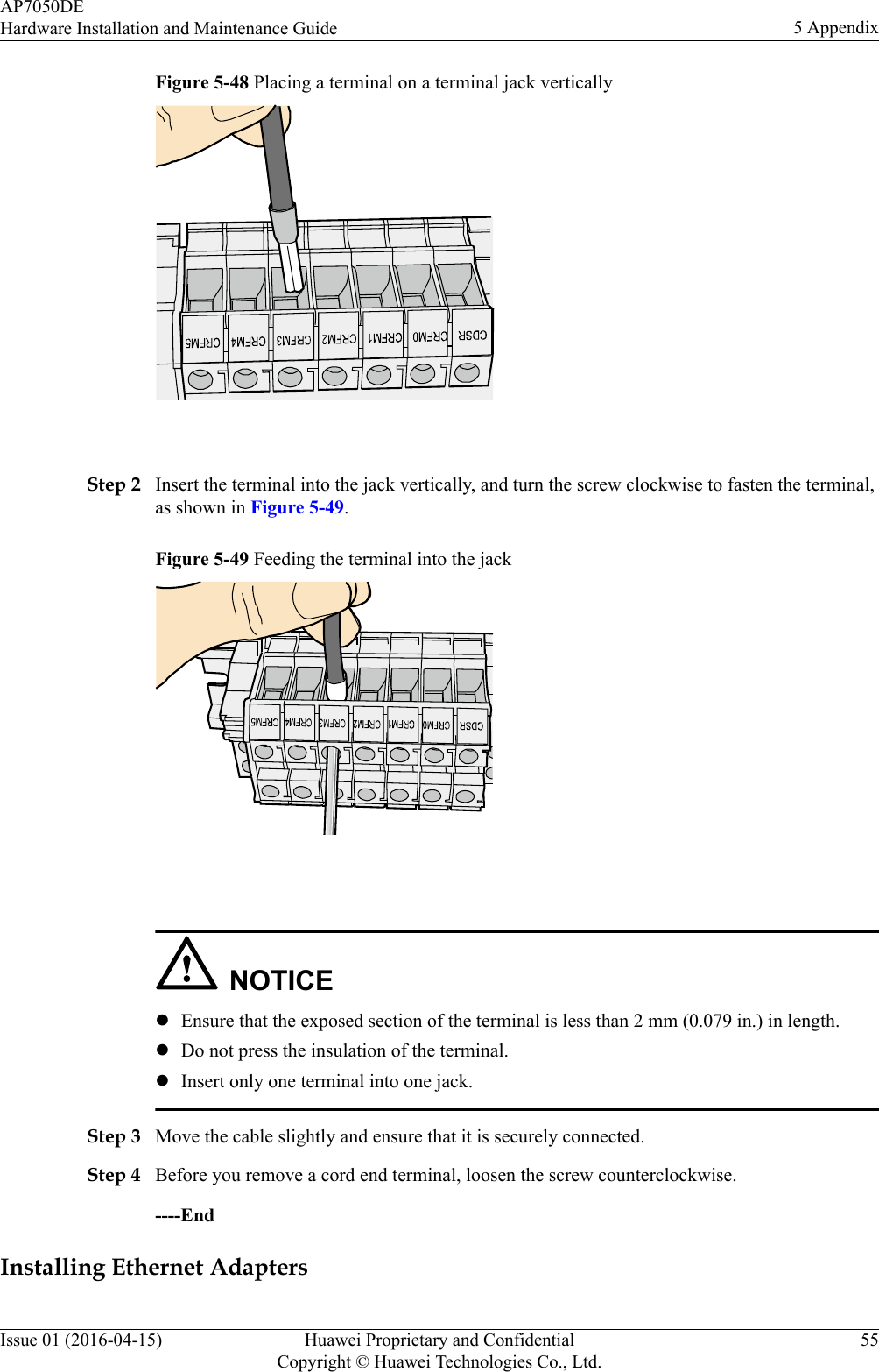
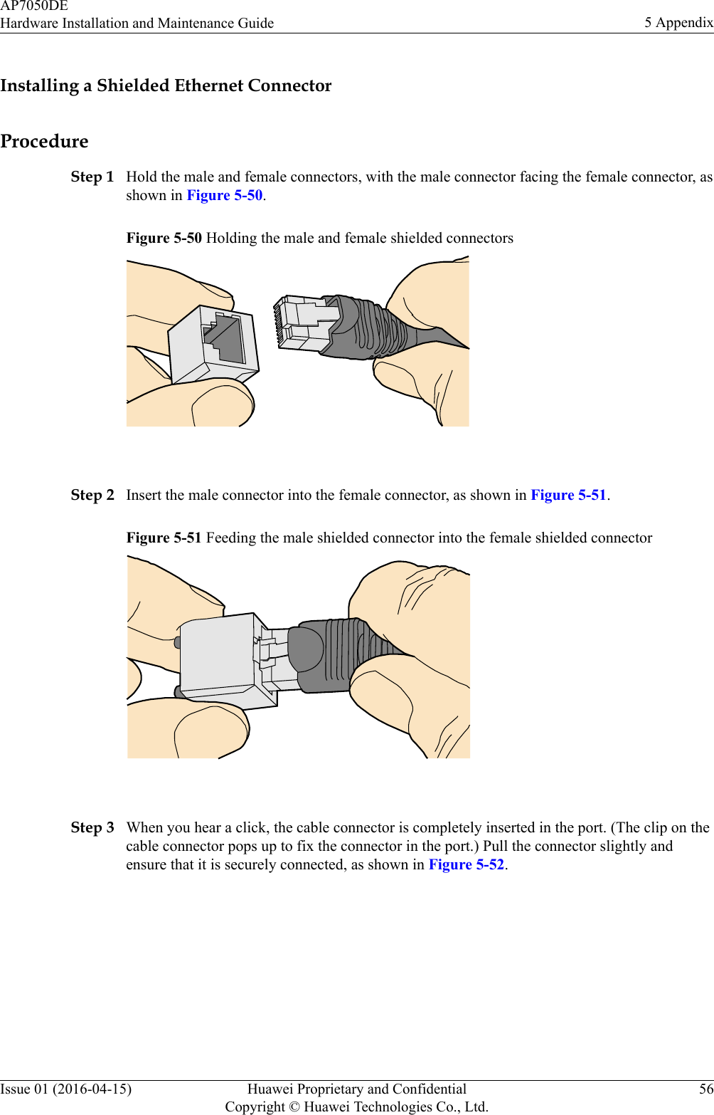
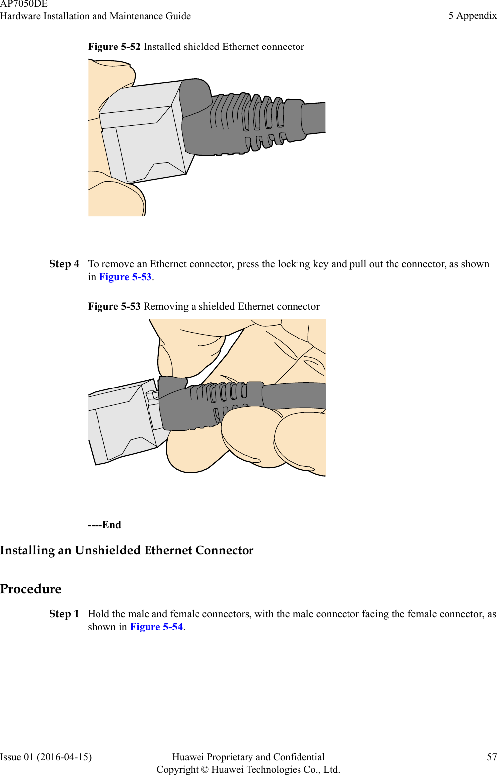
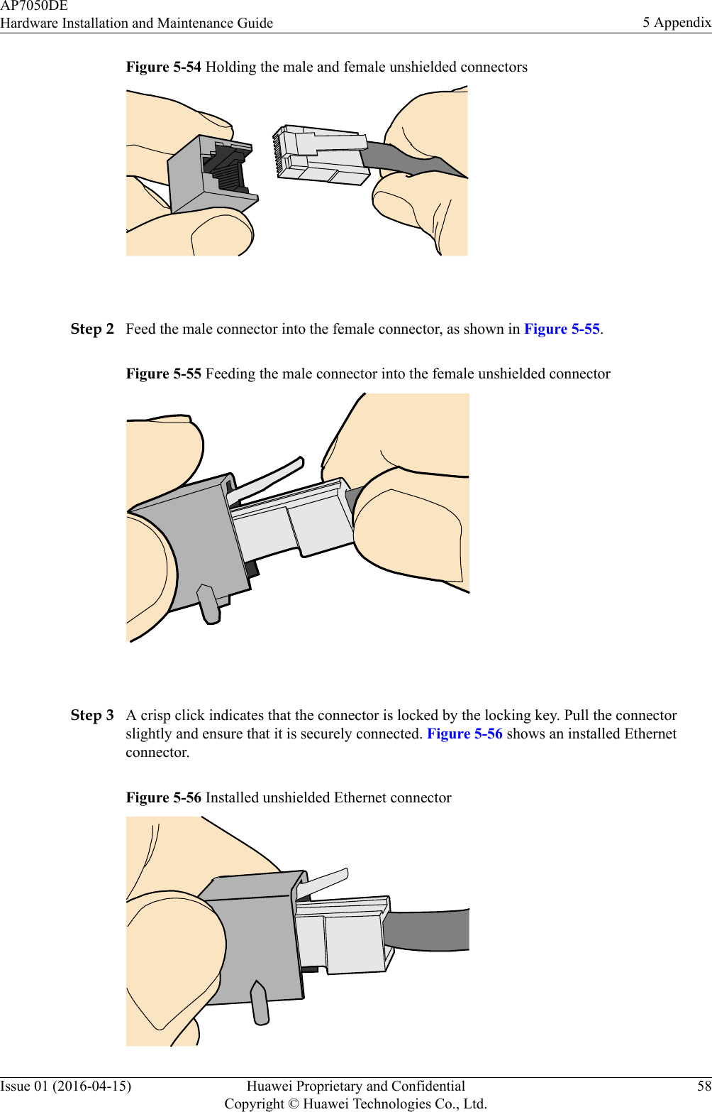
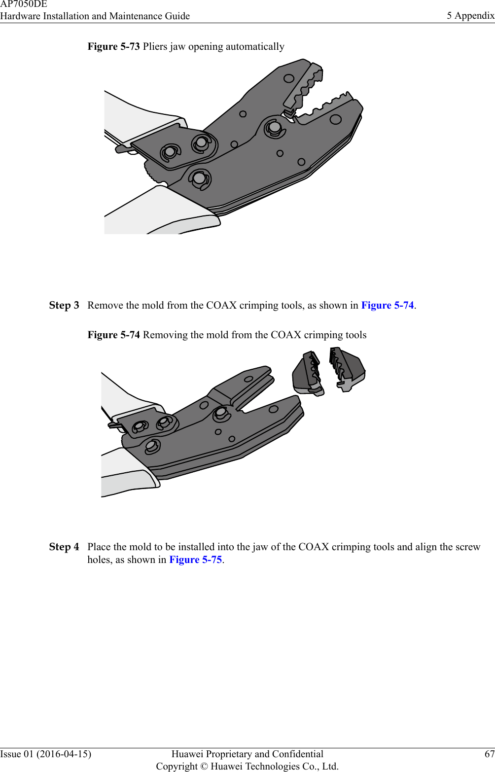
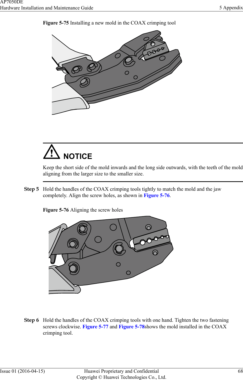
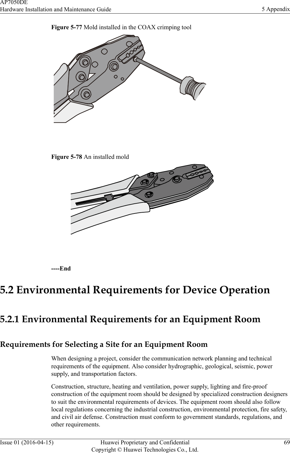
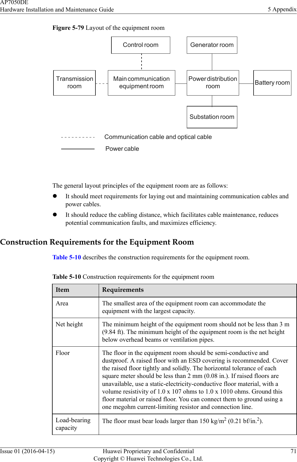
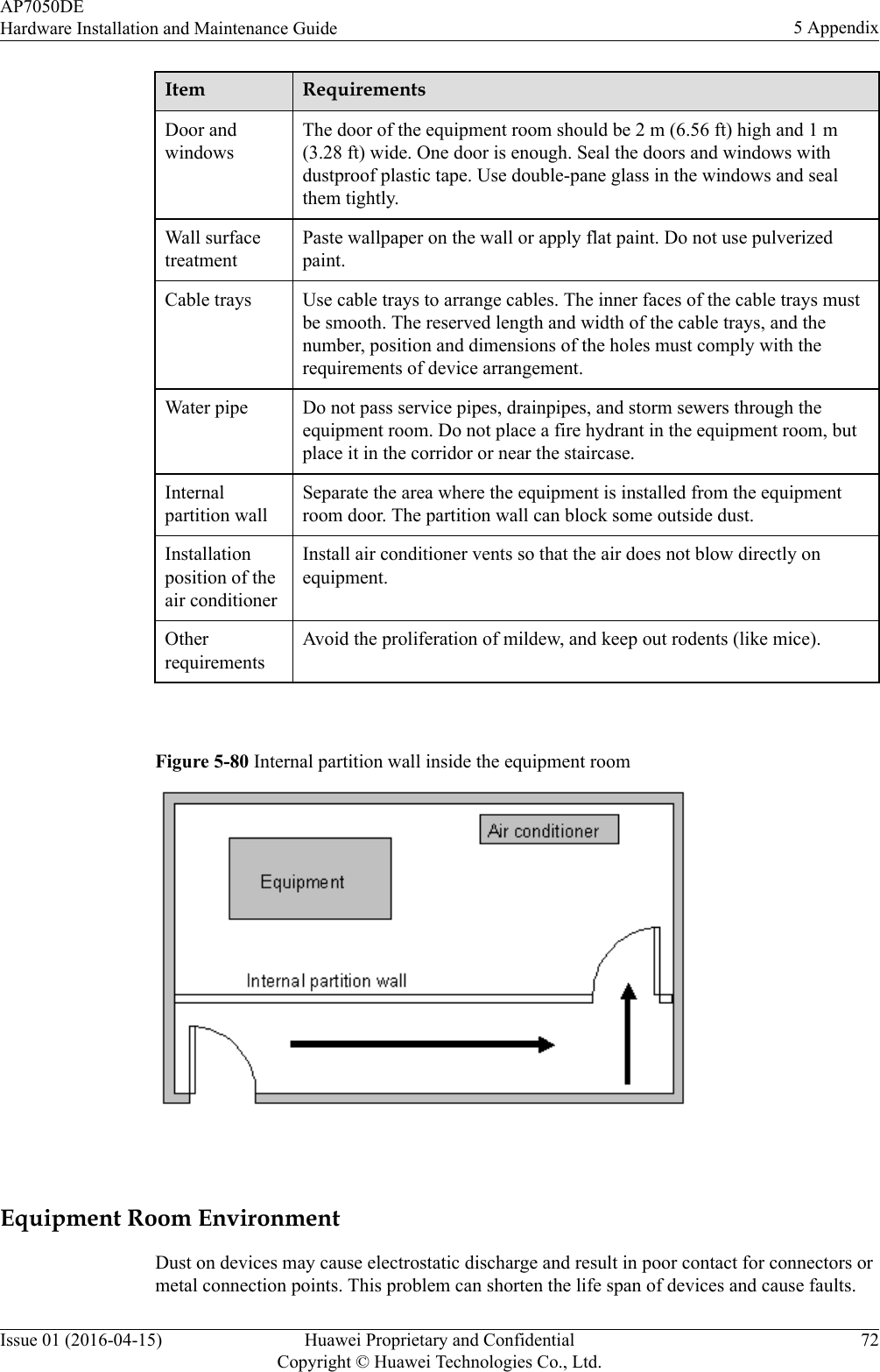
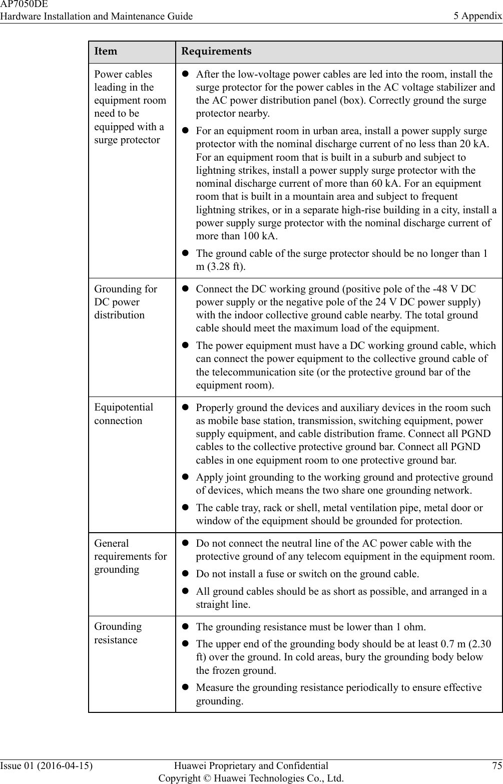
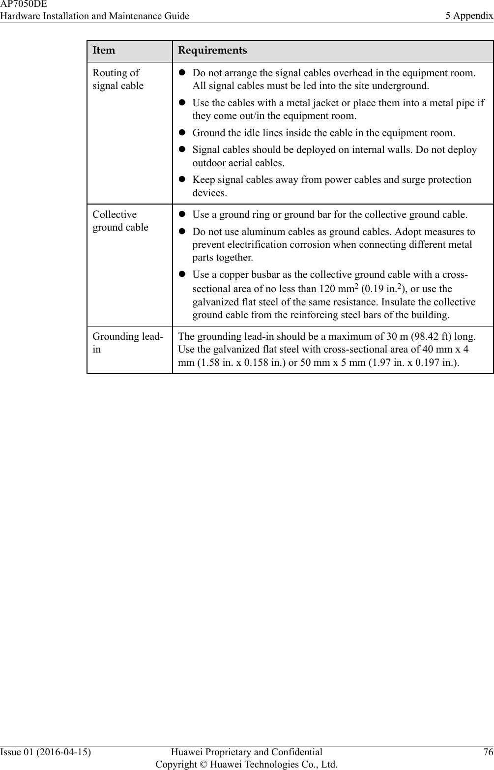
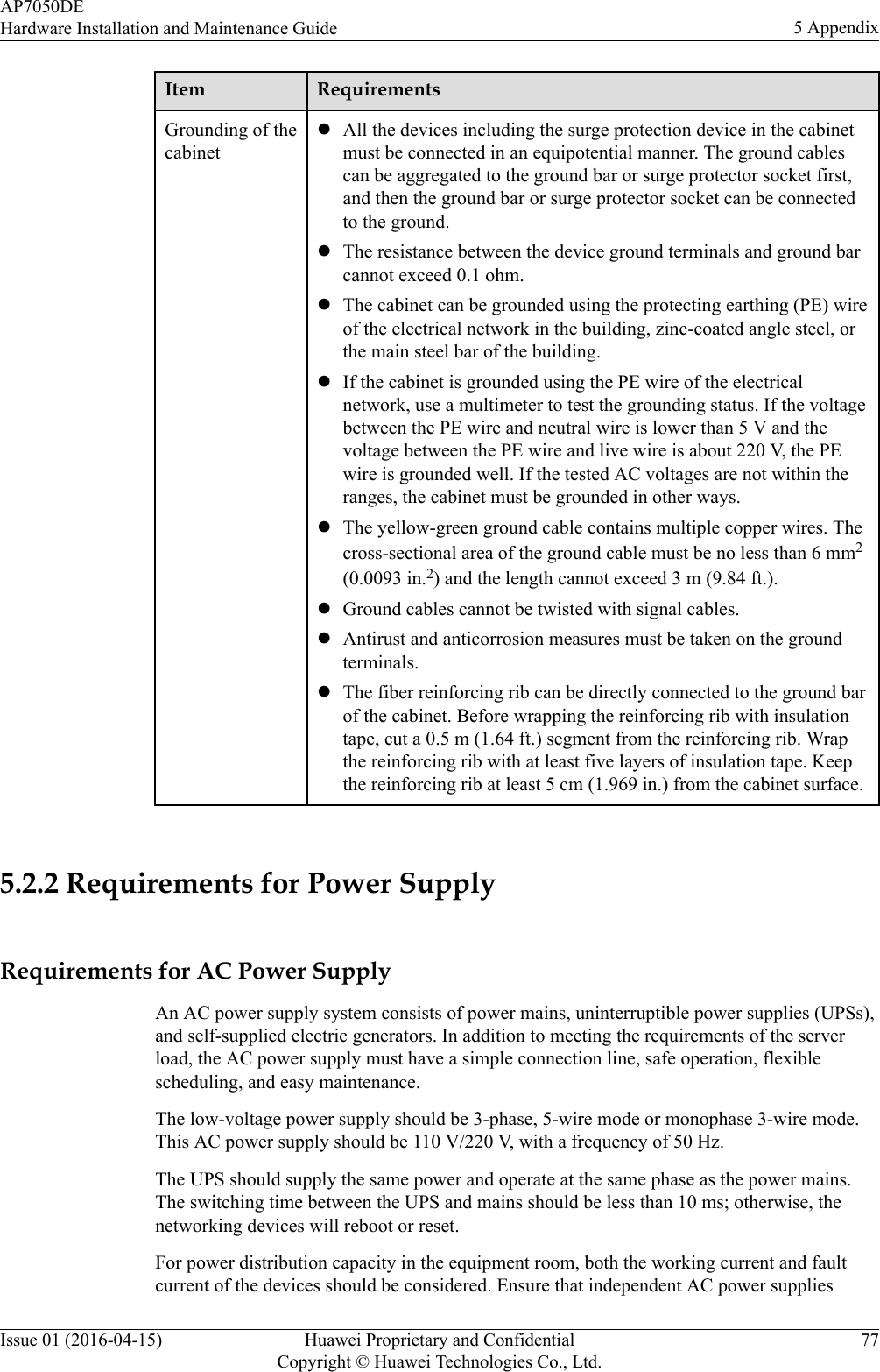
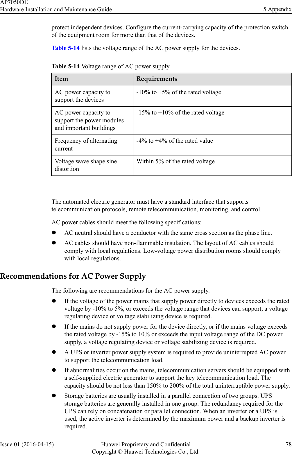
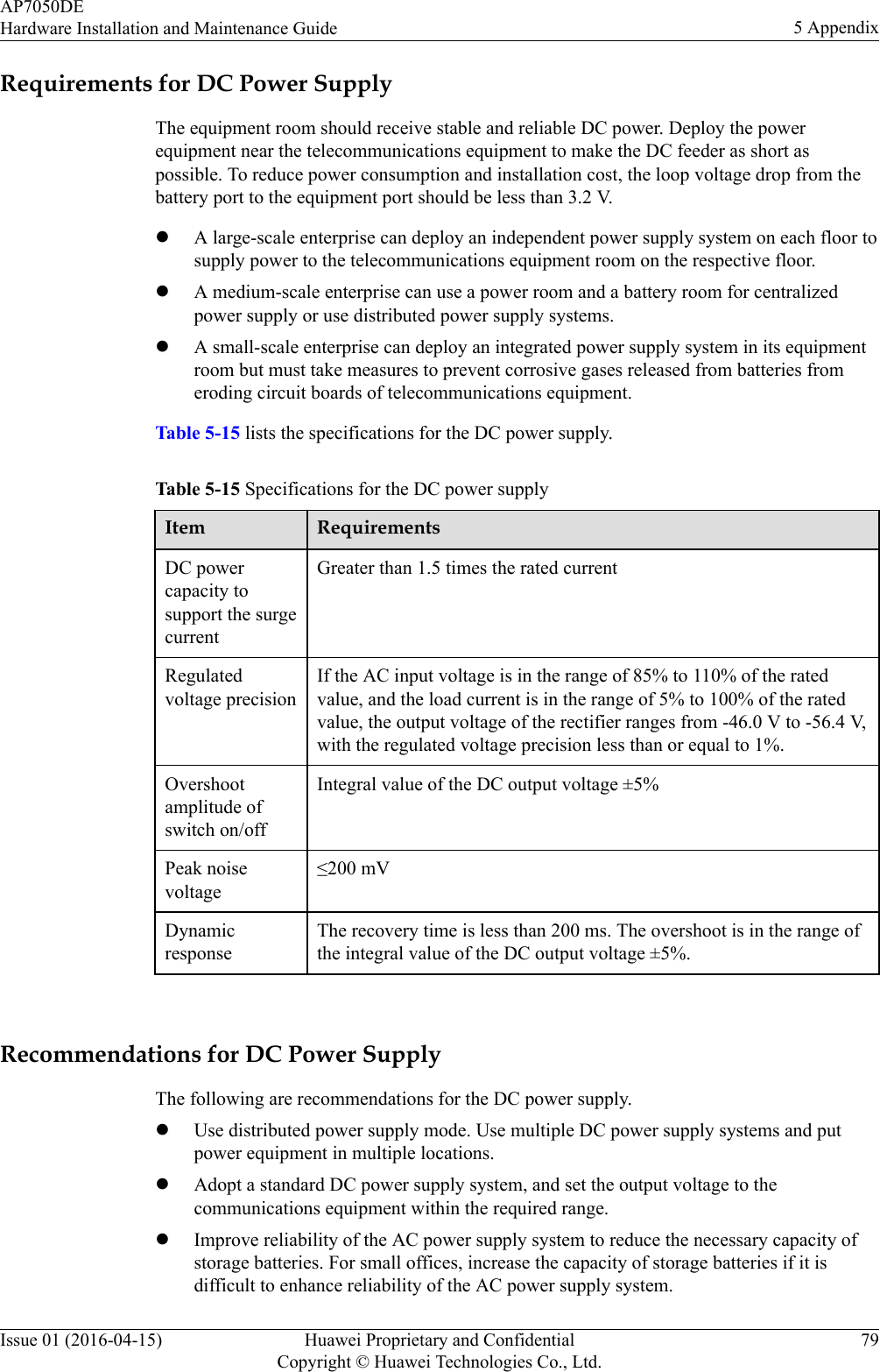
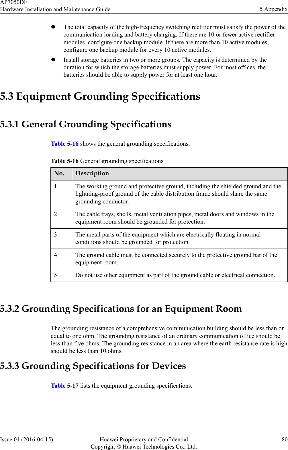
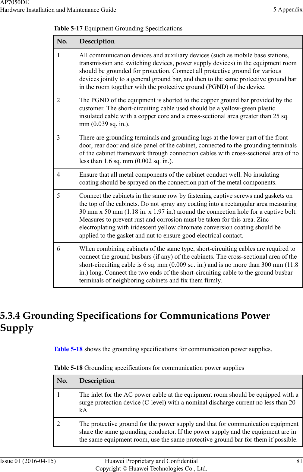
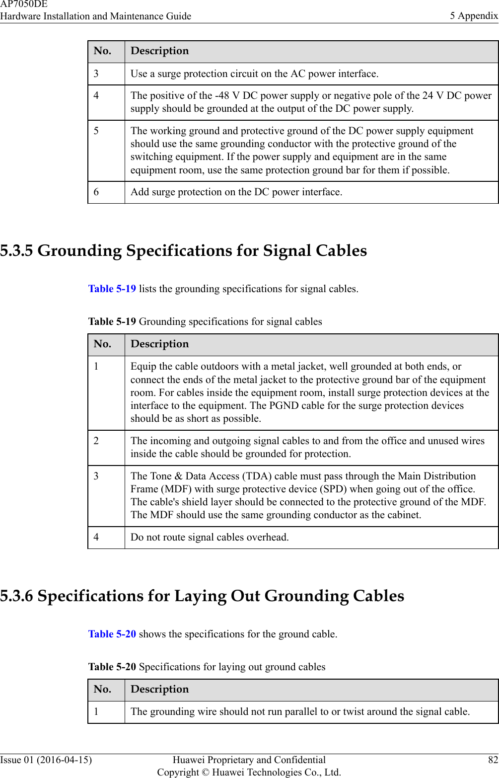
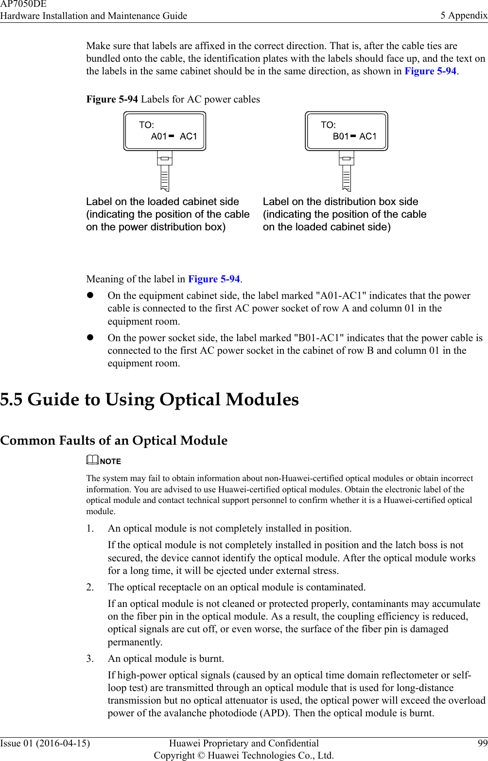
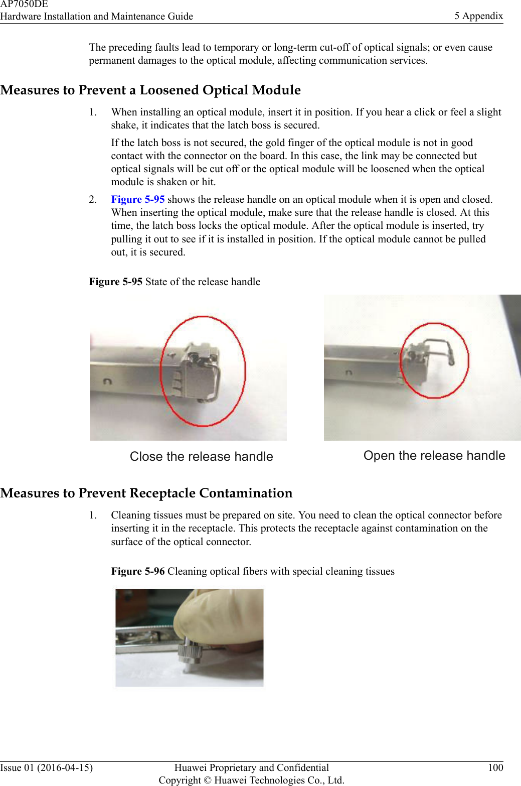
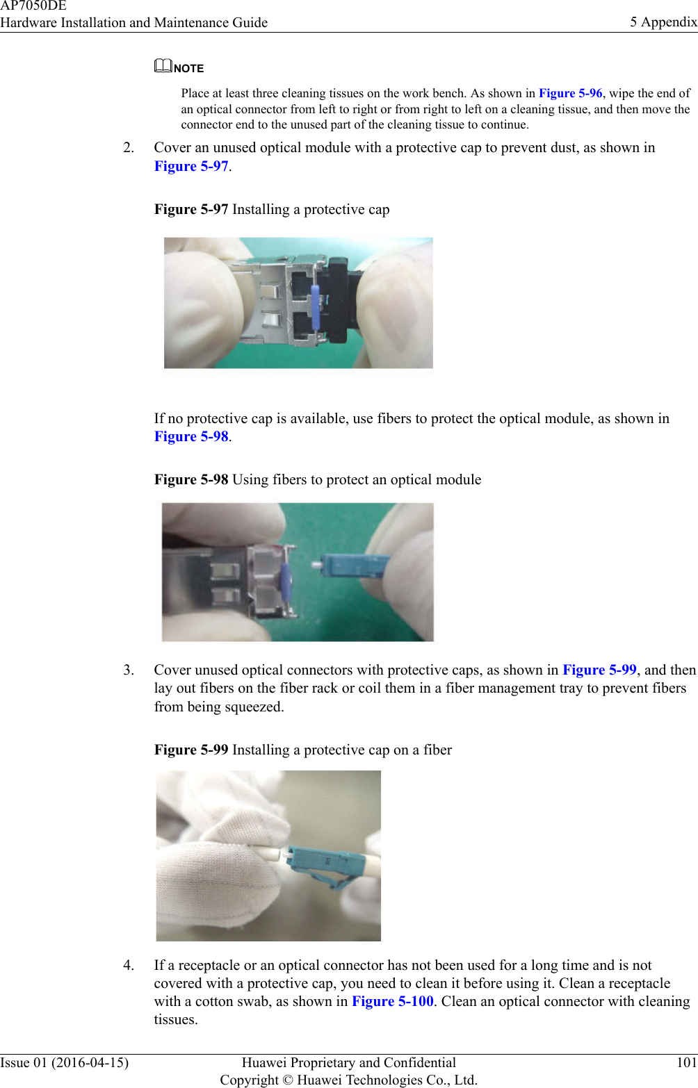
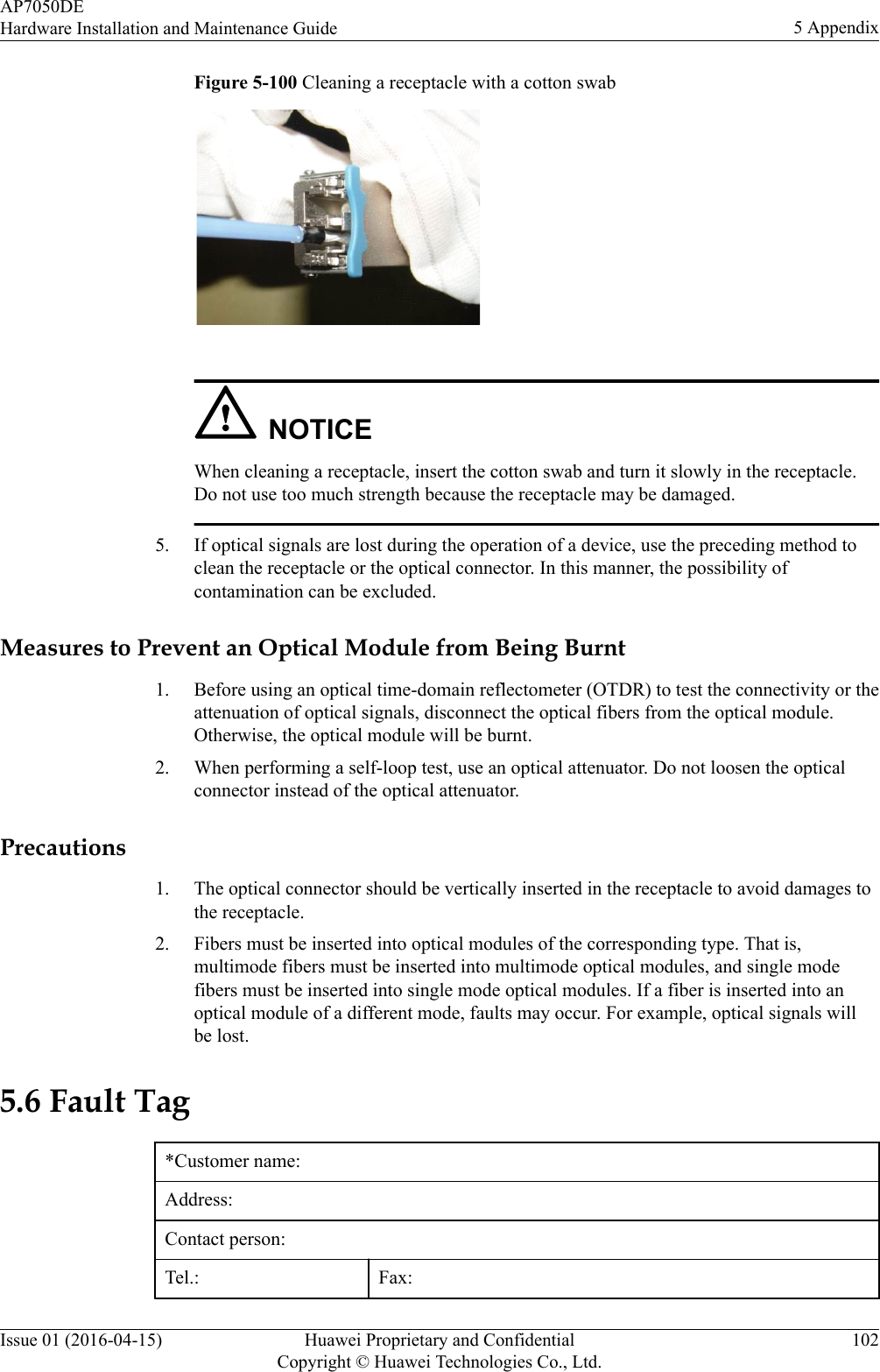
User ManualHardware Installation and Maintenance Guide