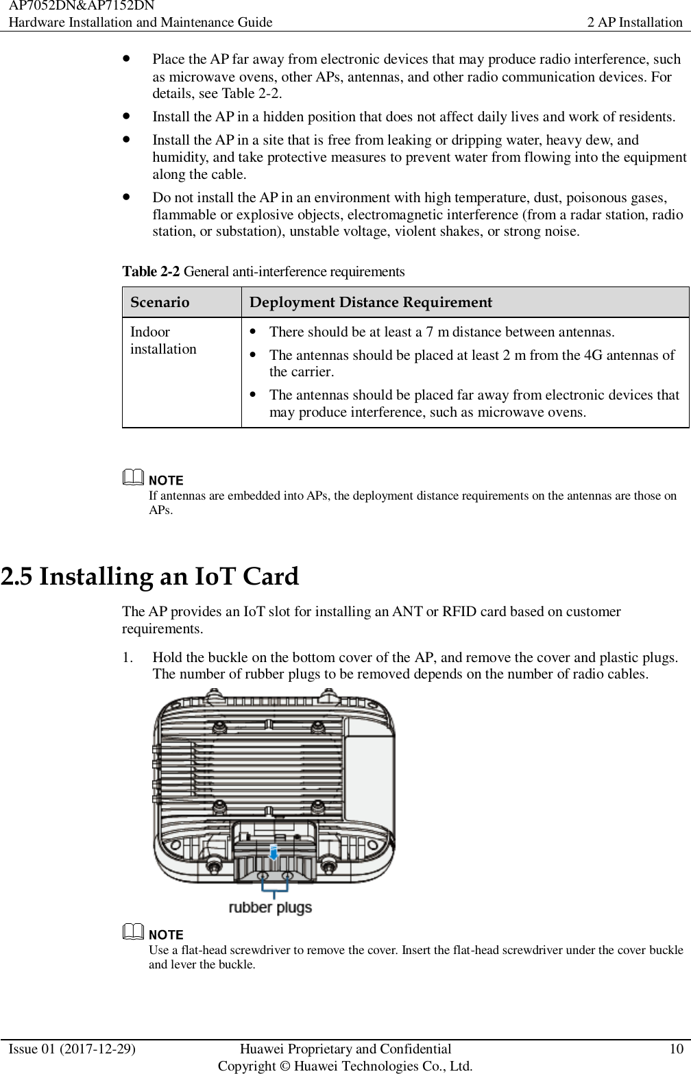
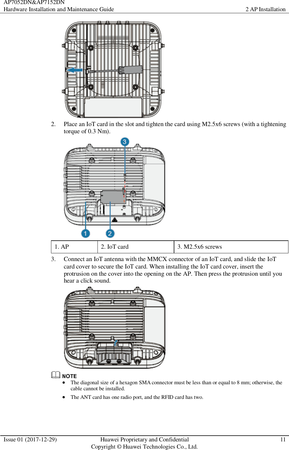
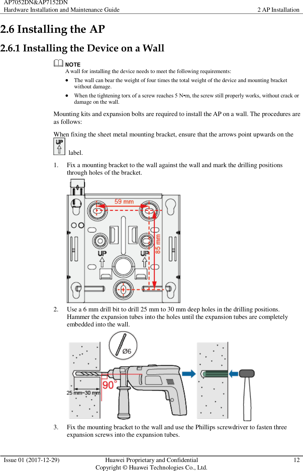
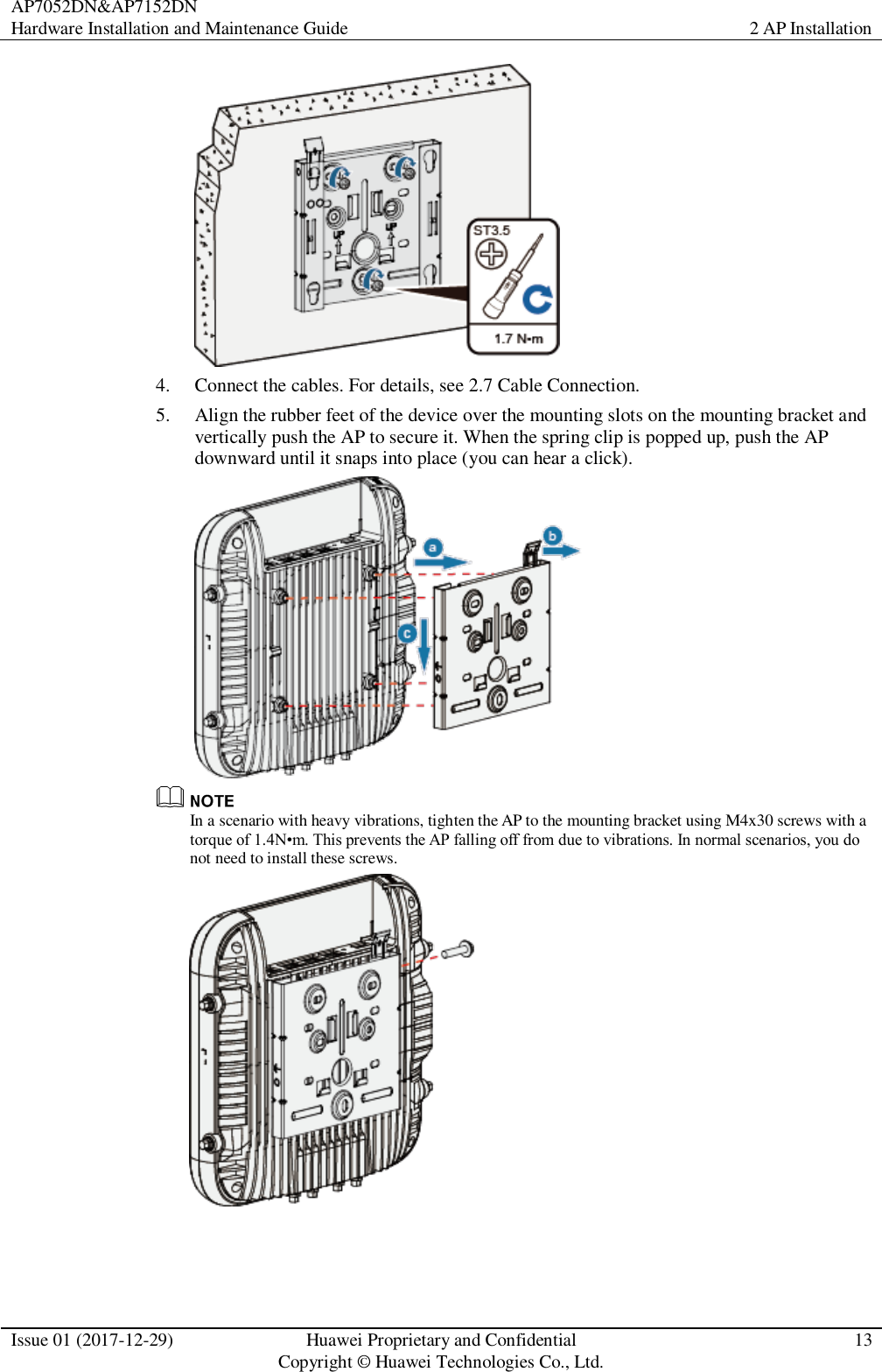
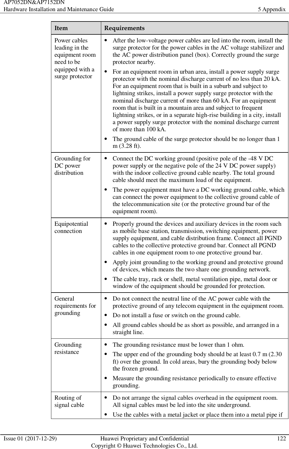
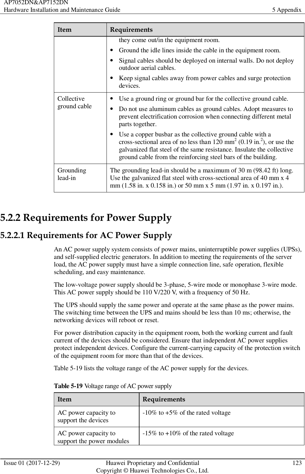
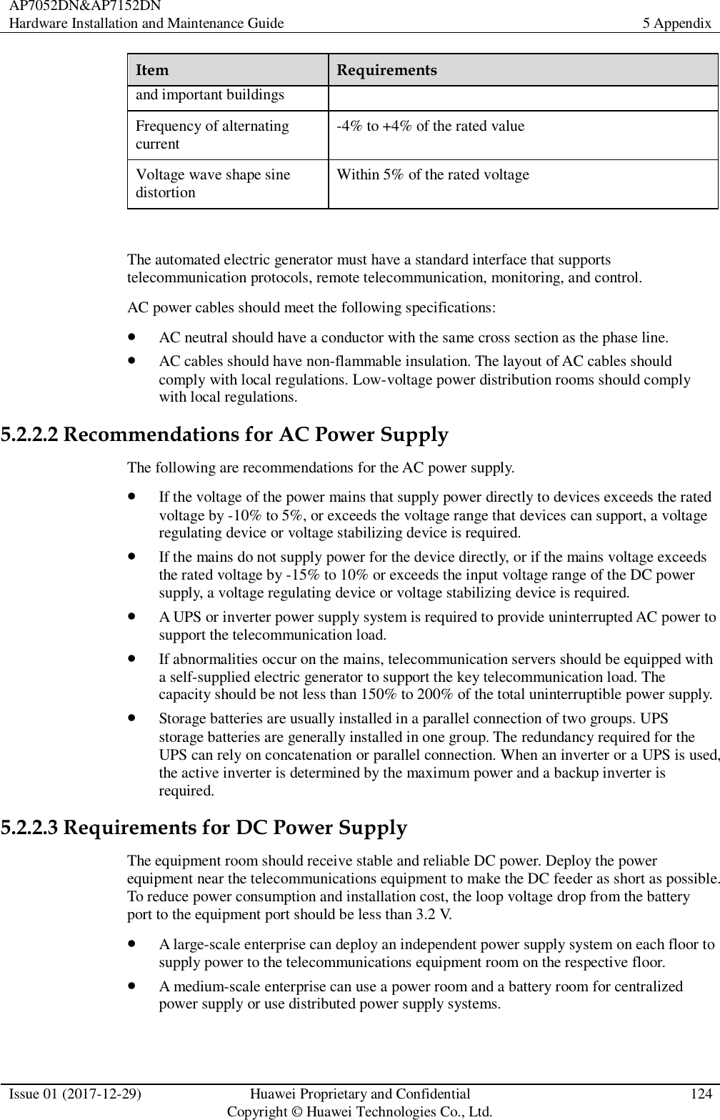
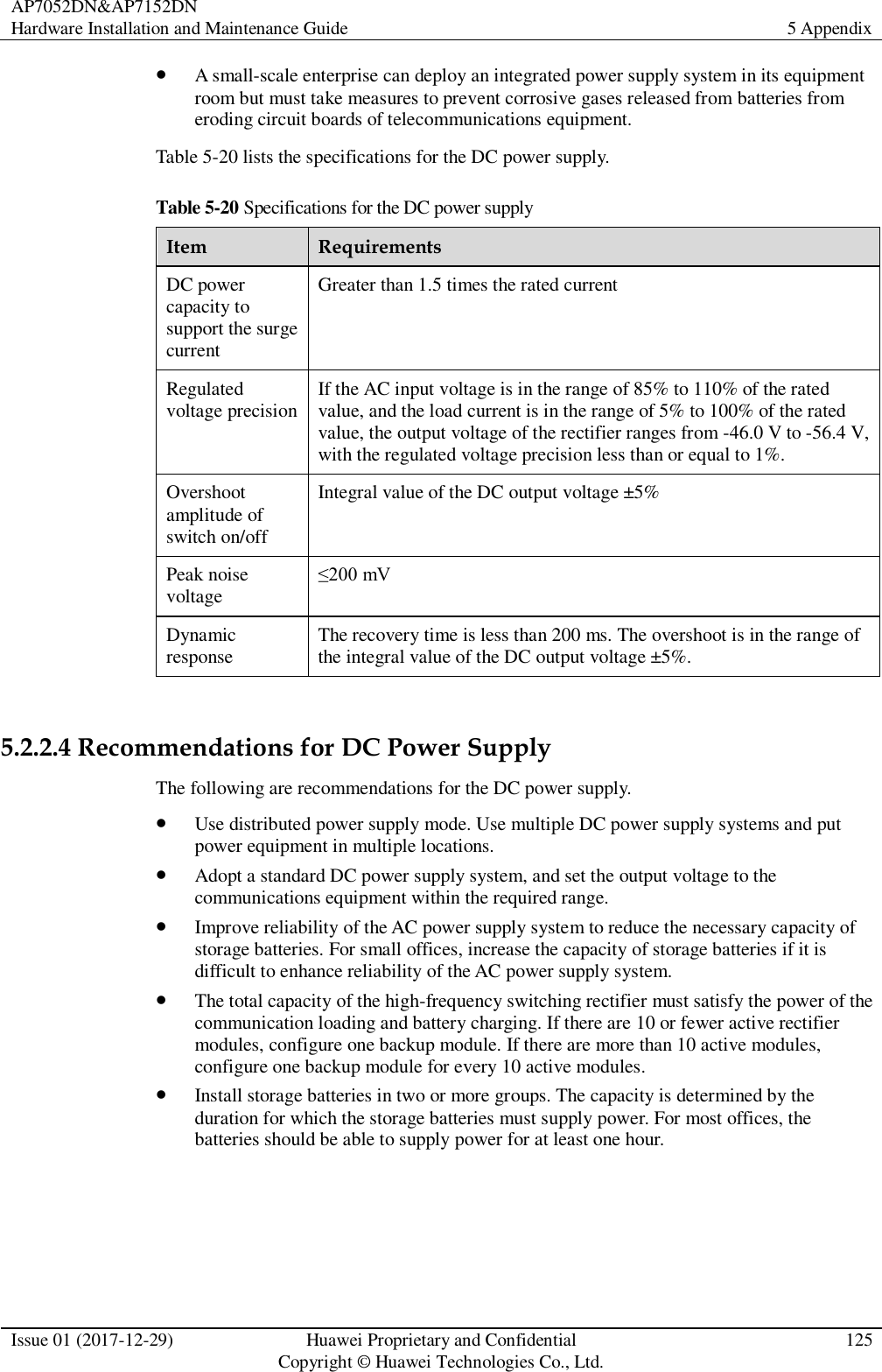
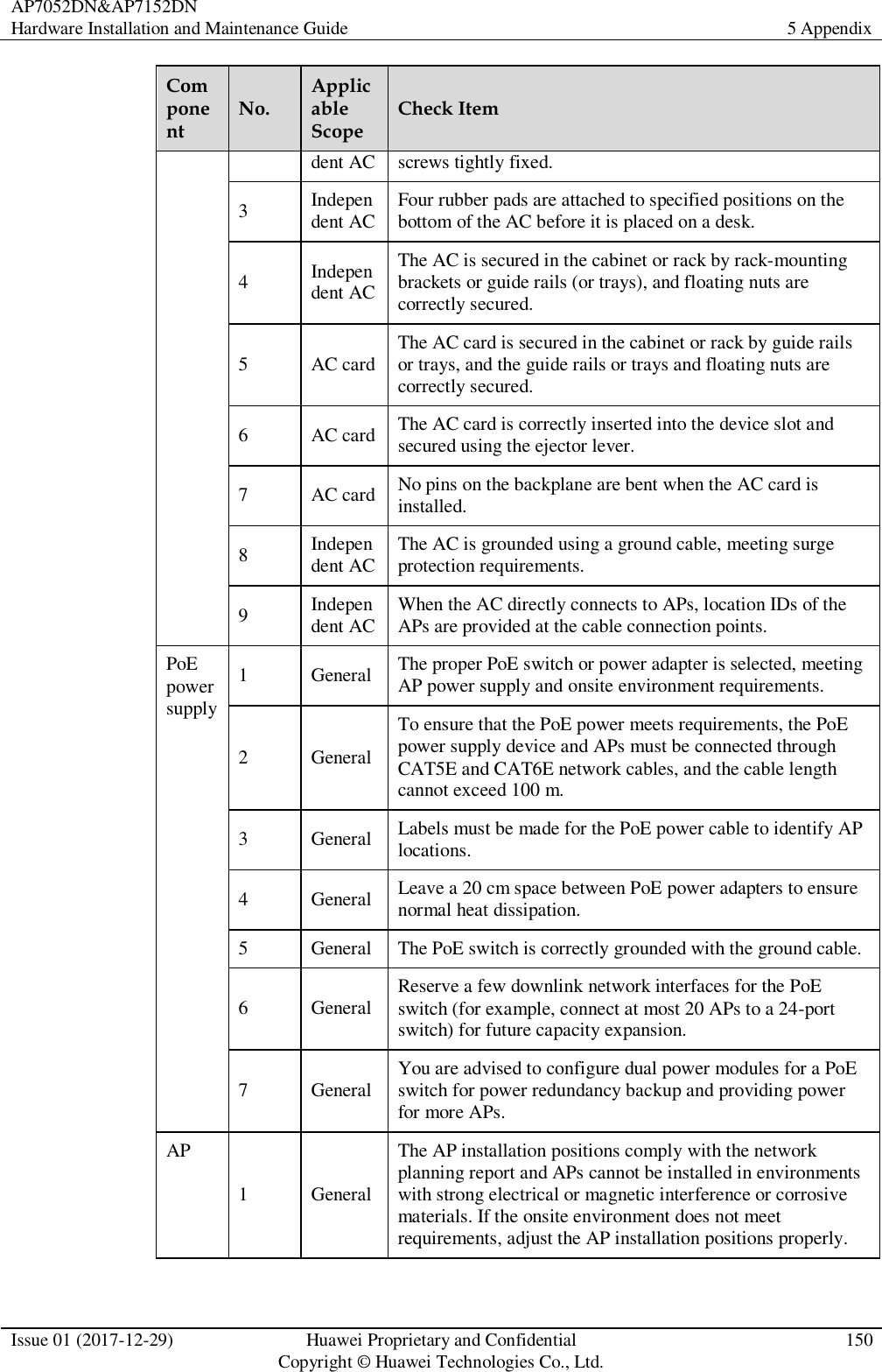
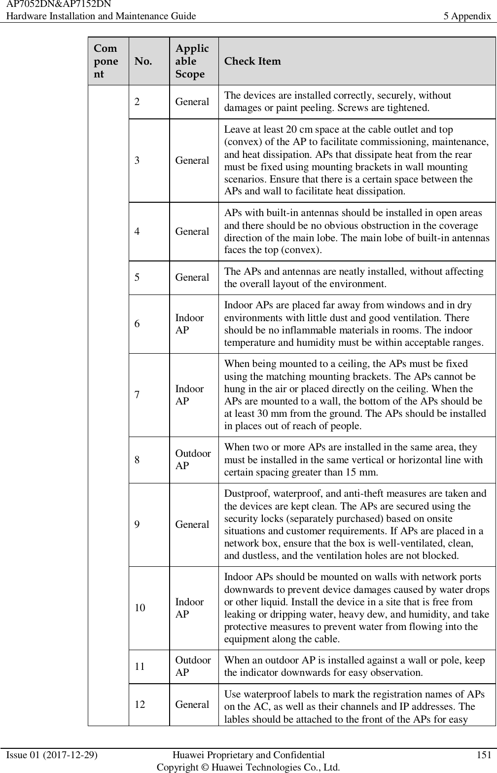
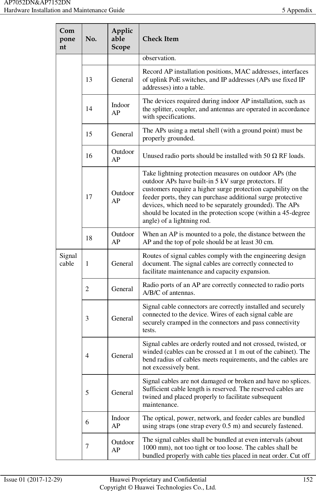
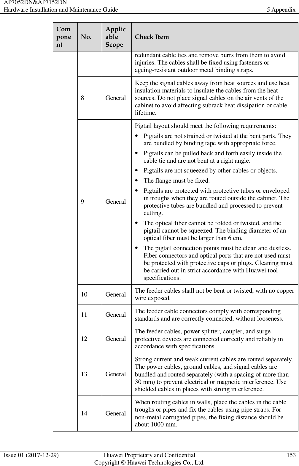
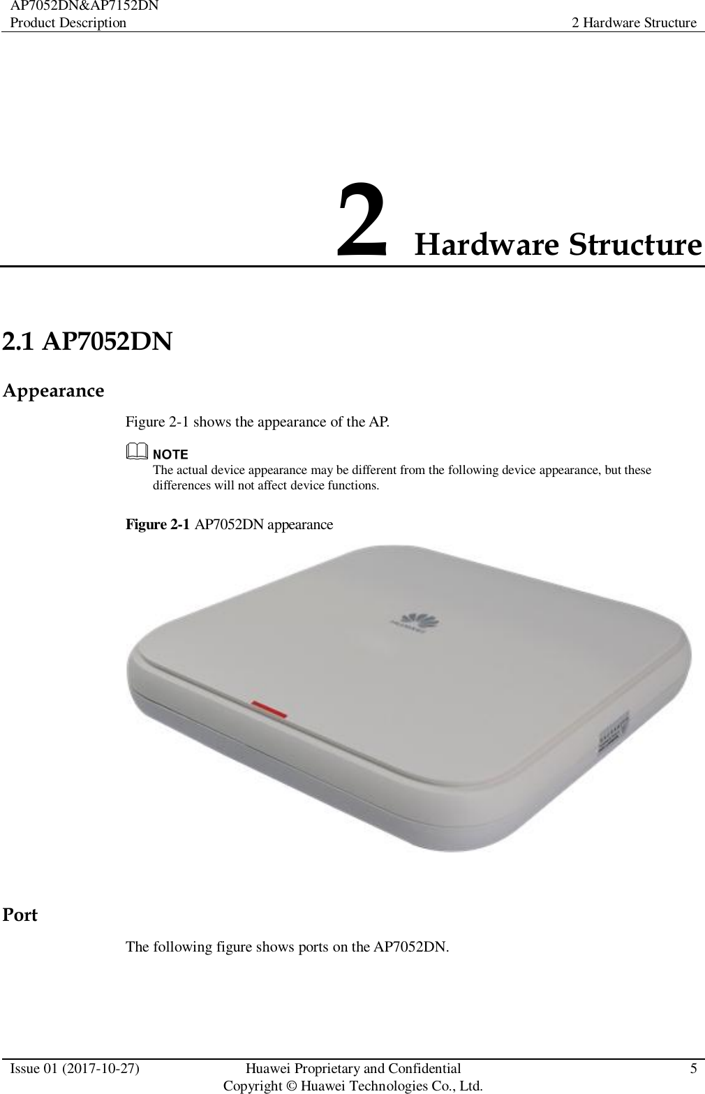
Huawei Technologies AP7052DN Wireless LAN Access Point User Manual Hardware Installation and Maintenance Guide
Huawei Technologies Co.,Ltd Wireless LAN Access Point Hardware Installation and Maintenance Guide
Contents
- 1. User guide
- 2. User manual
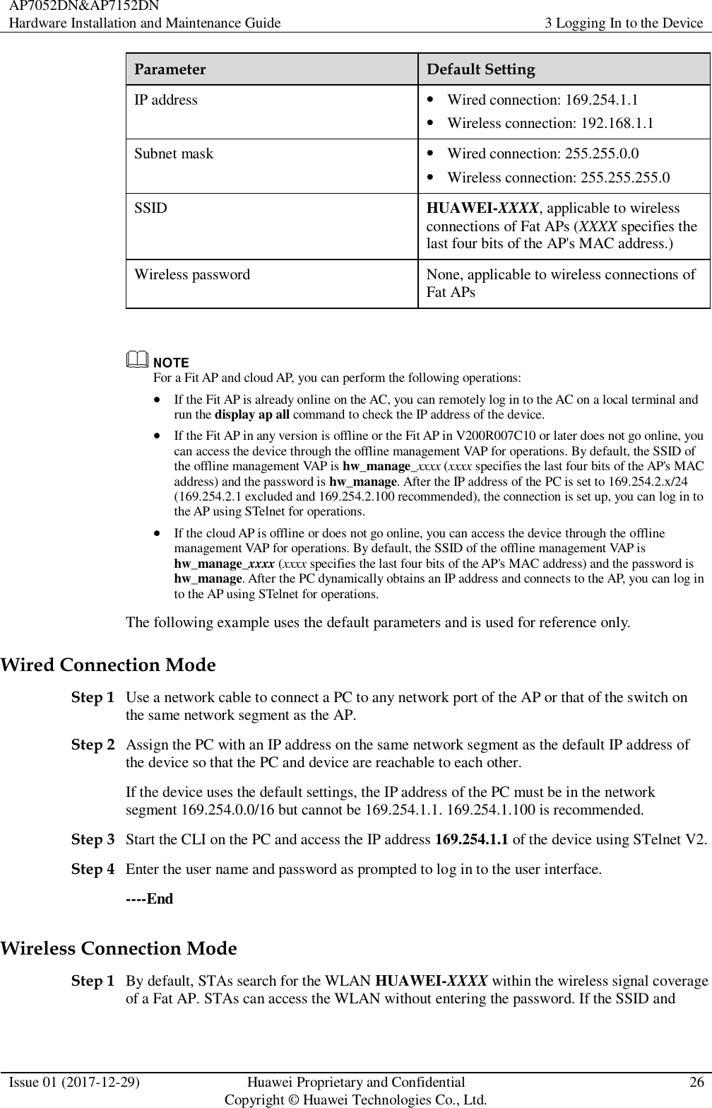
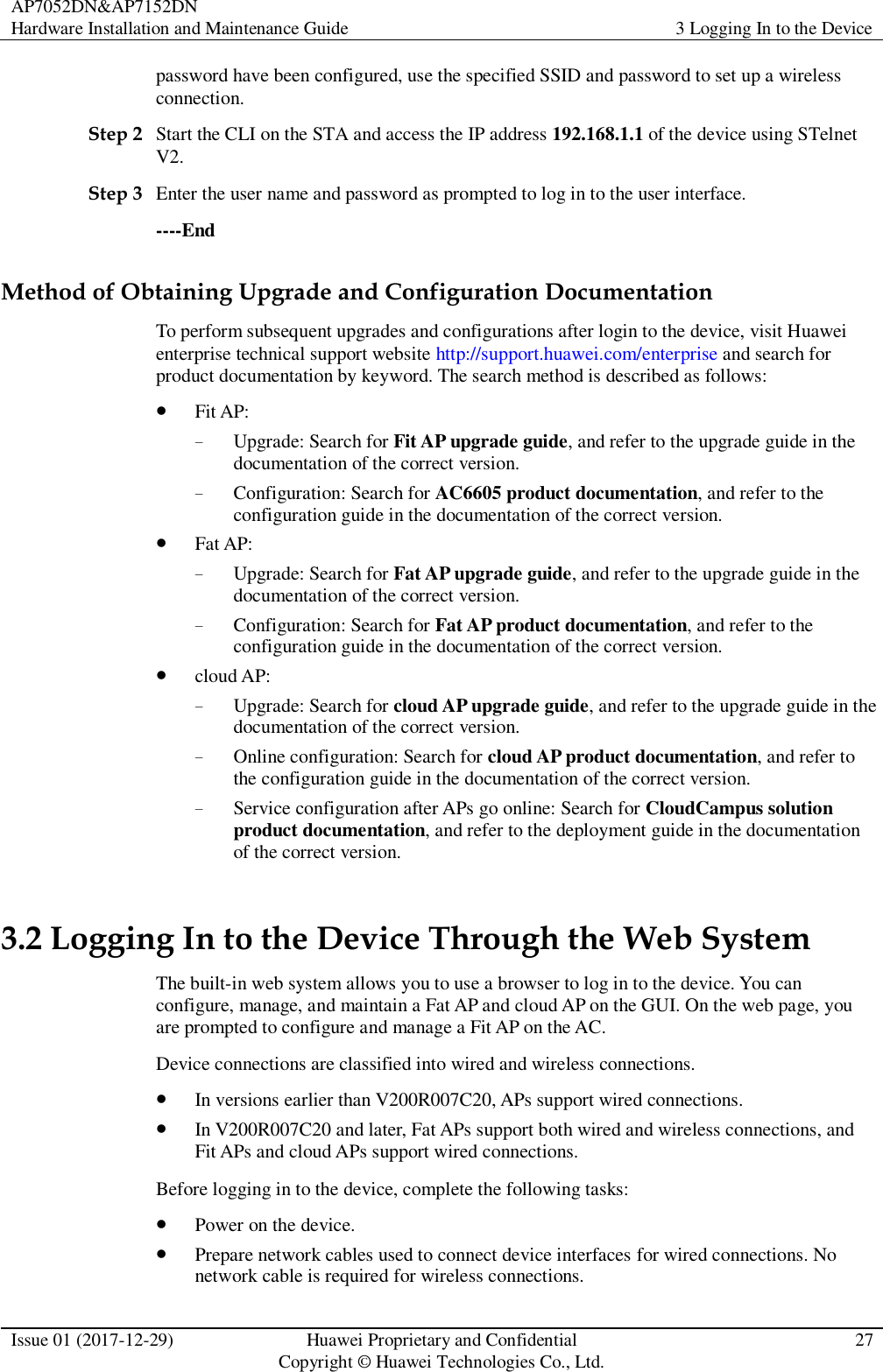
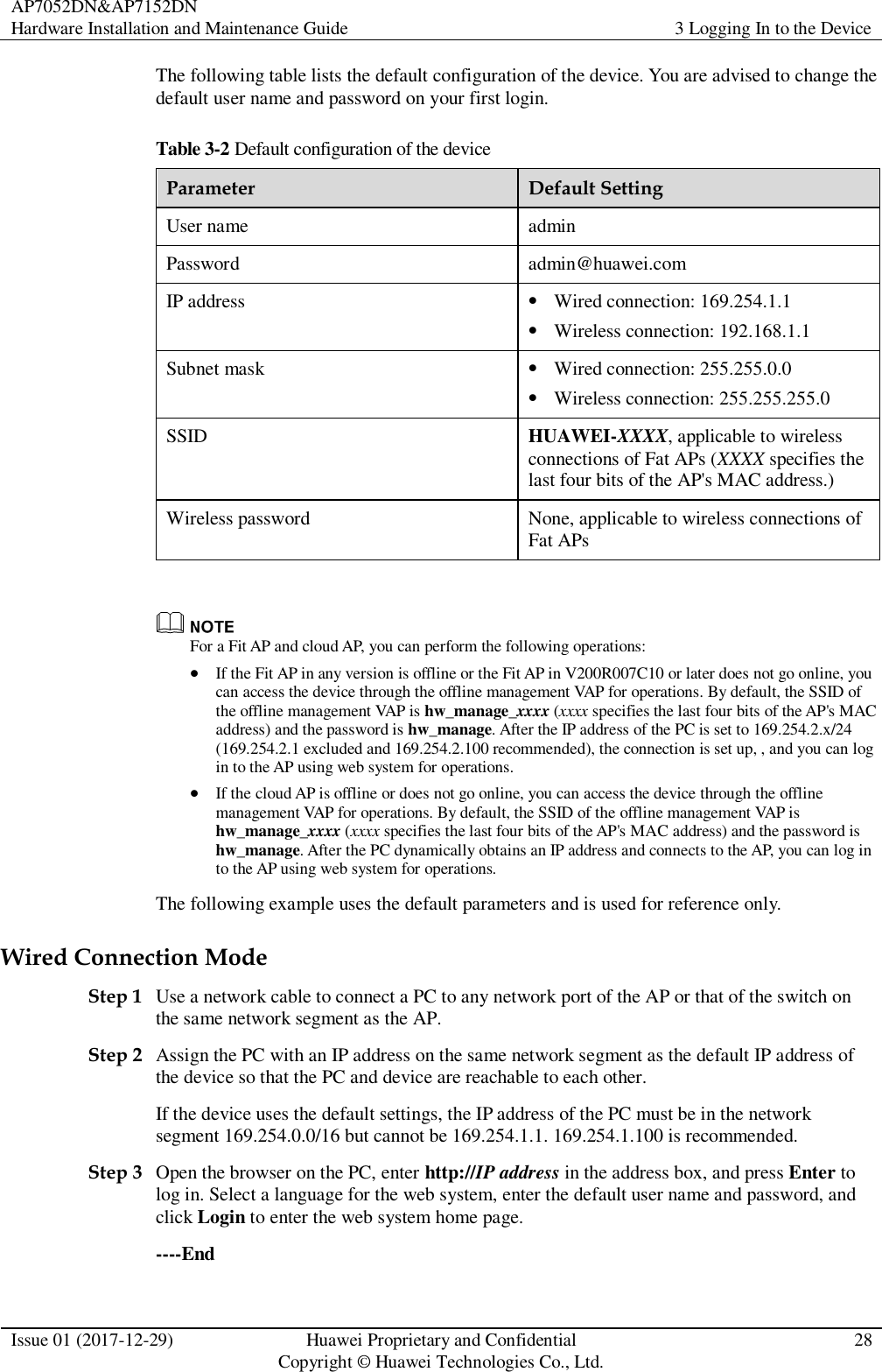
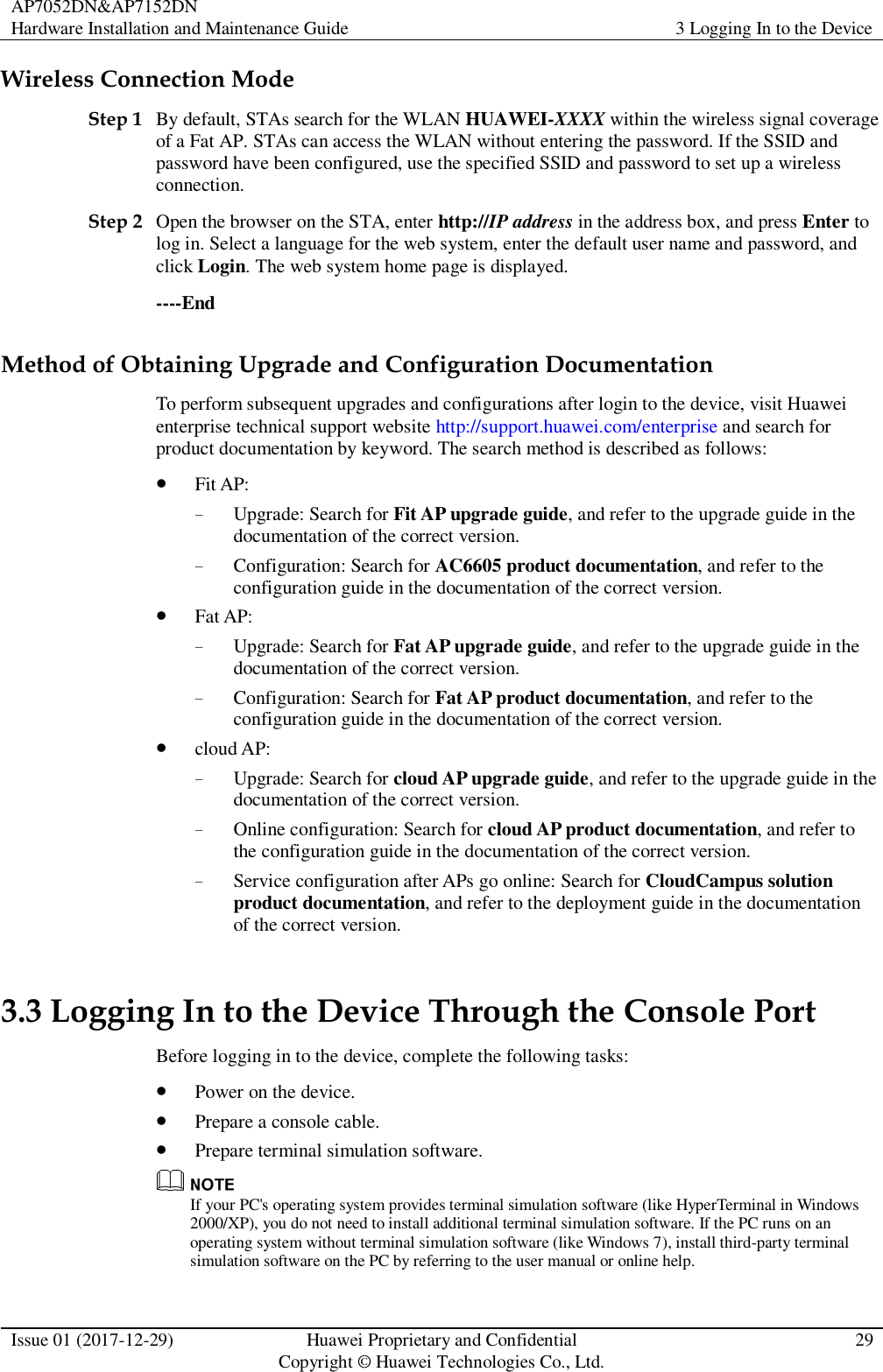
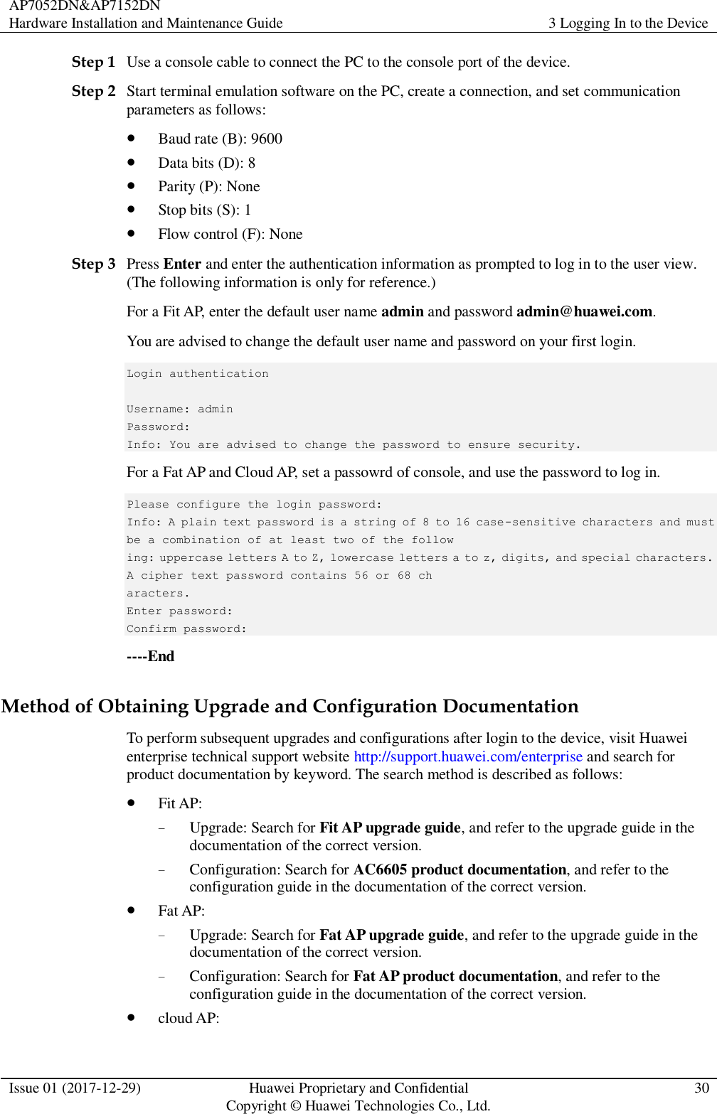
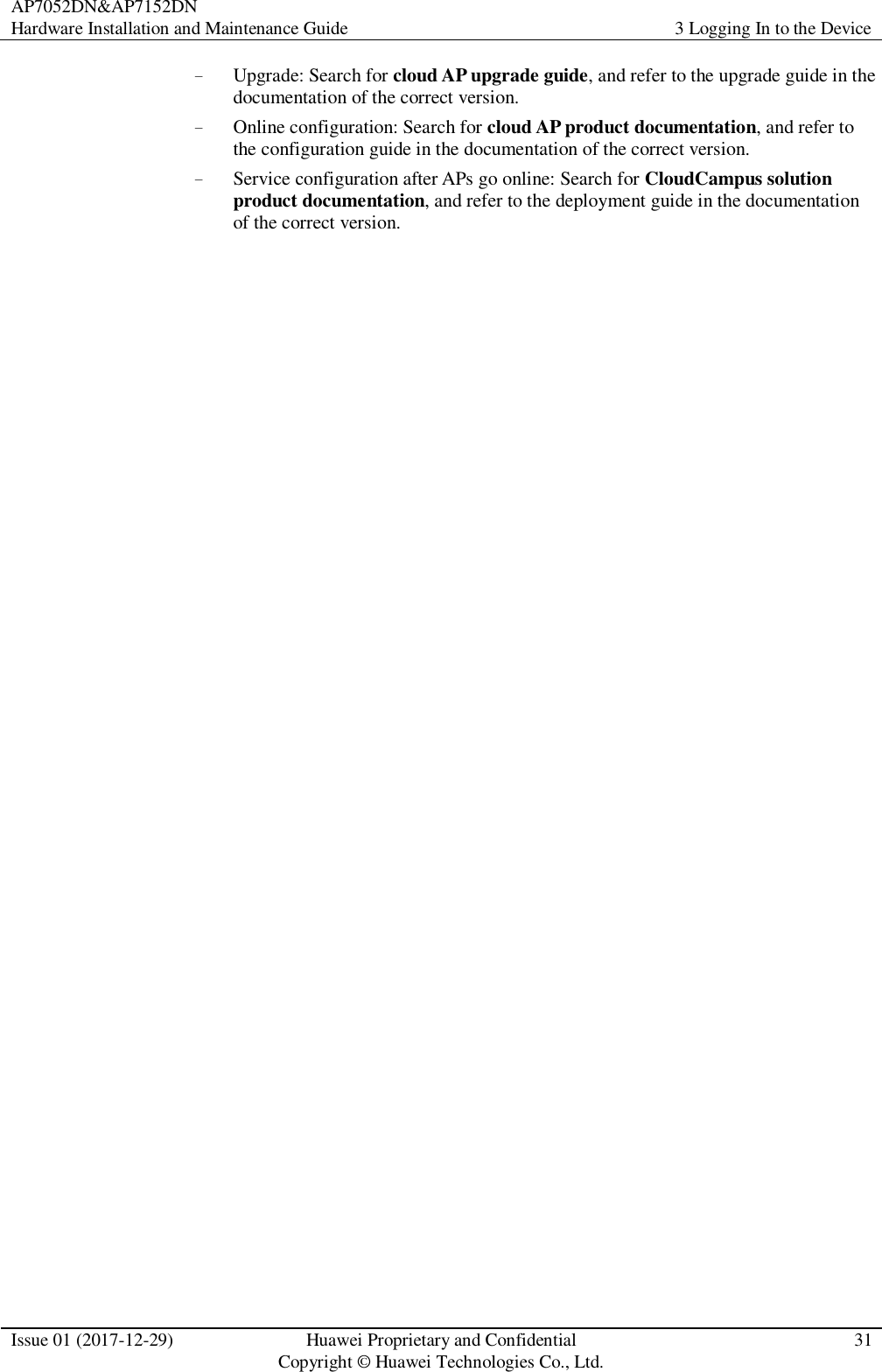
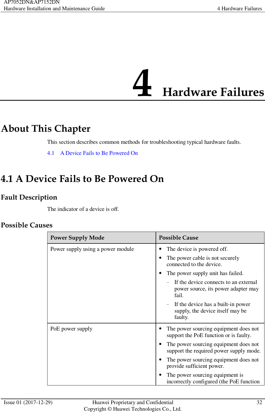
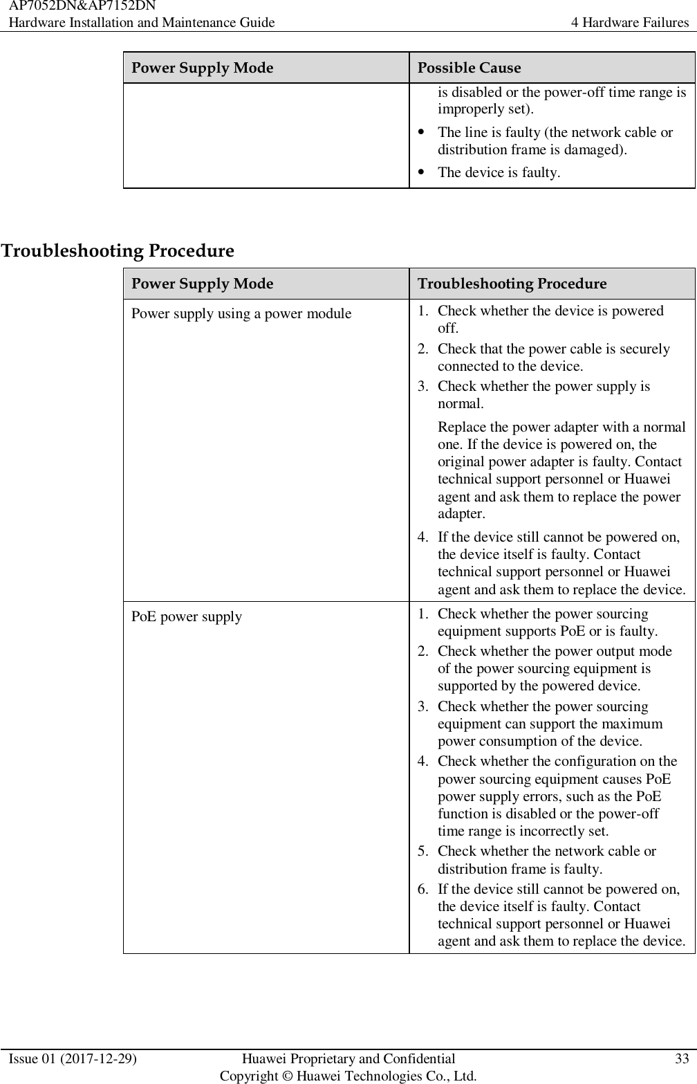
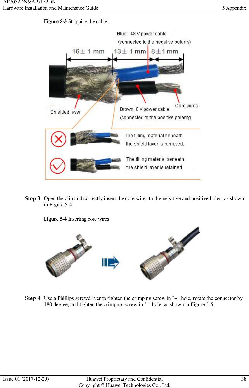
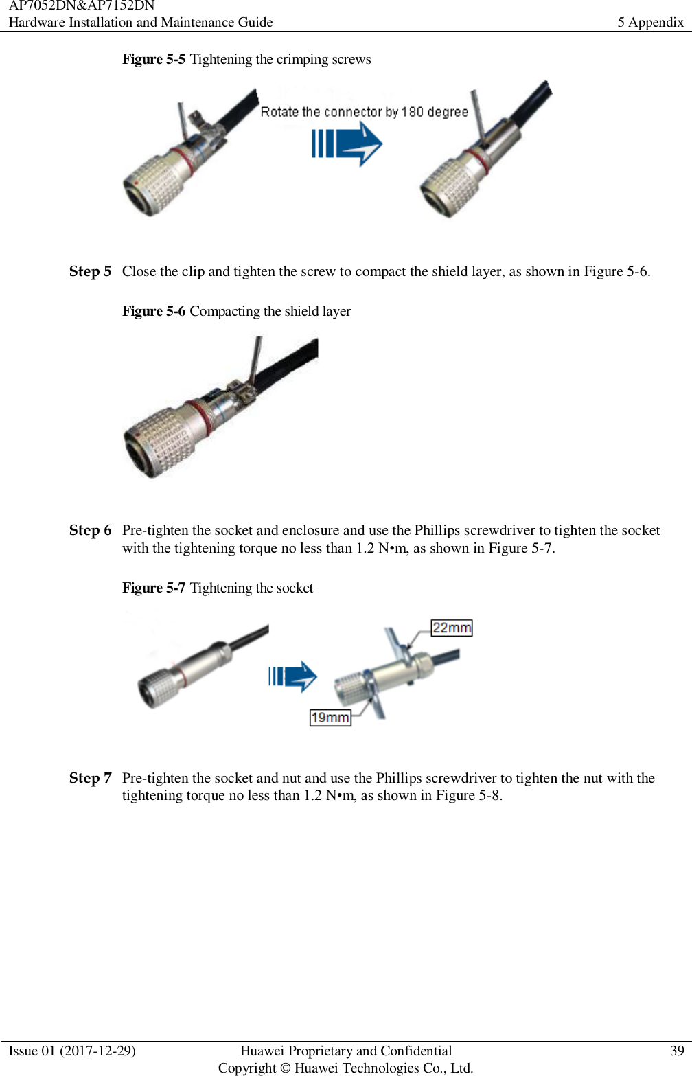
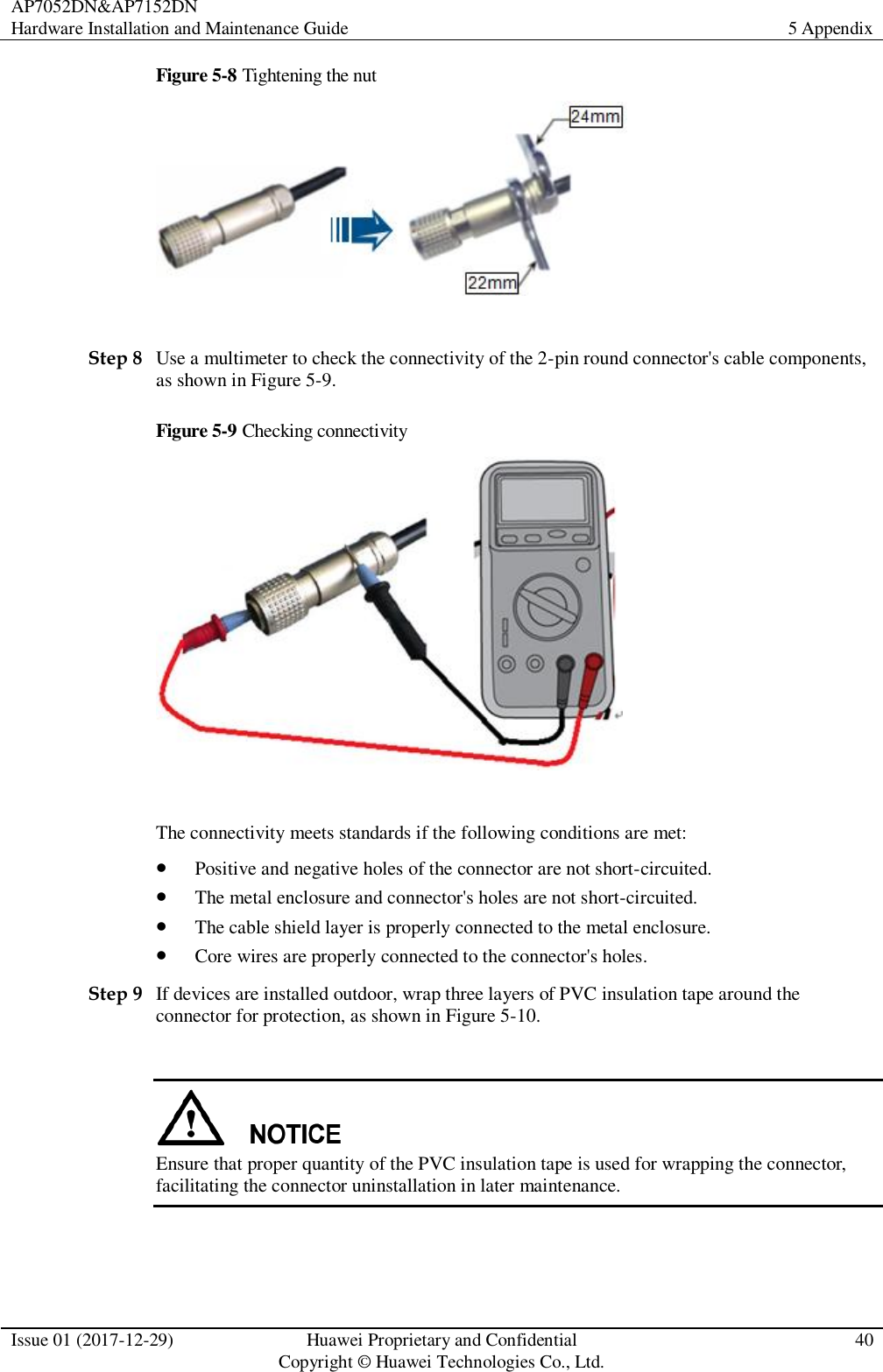
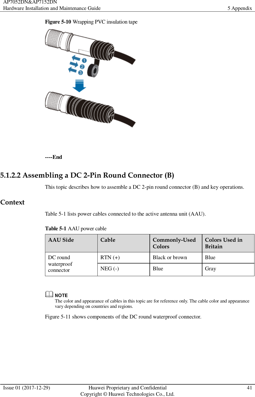
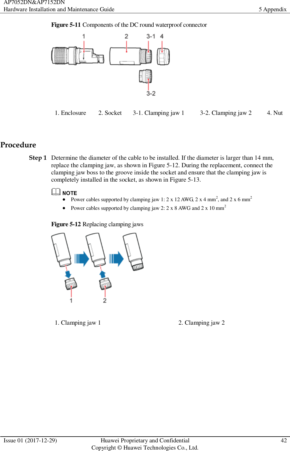
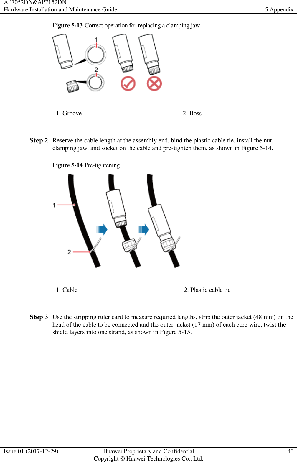
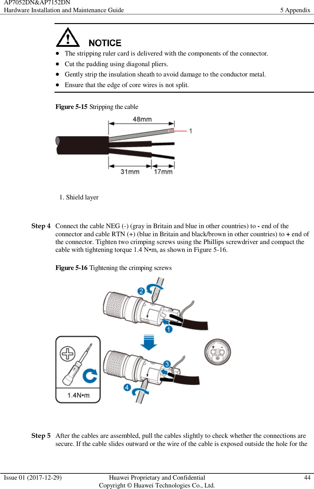
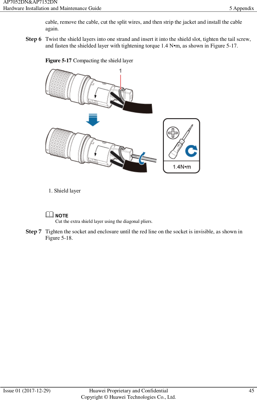
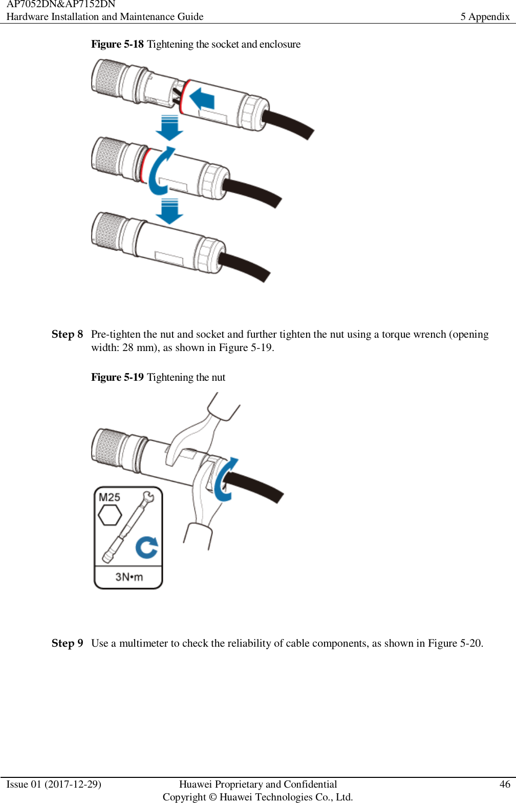
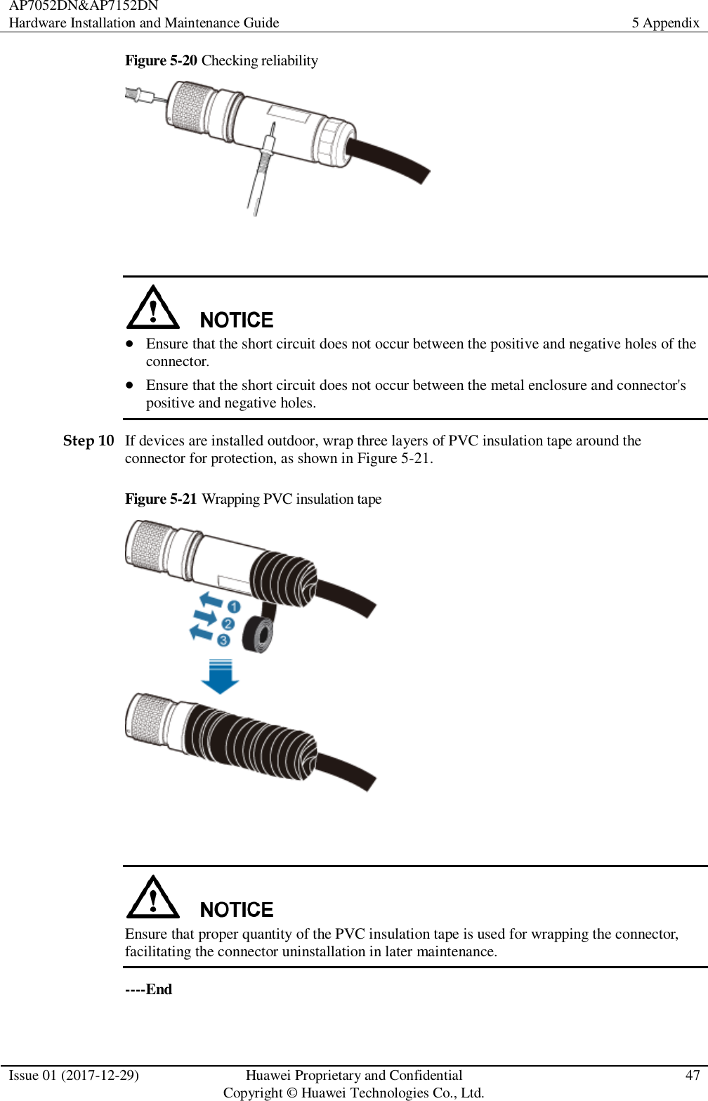
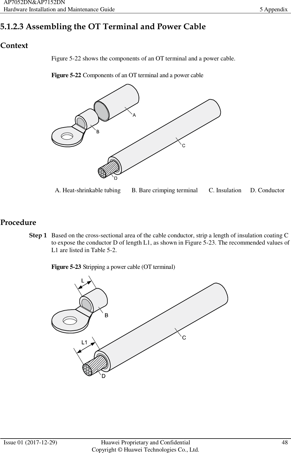
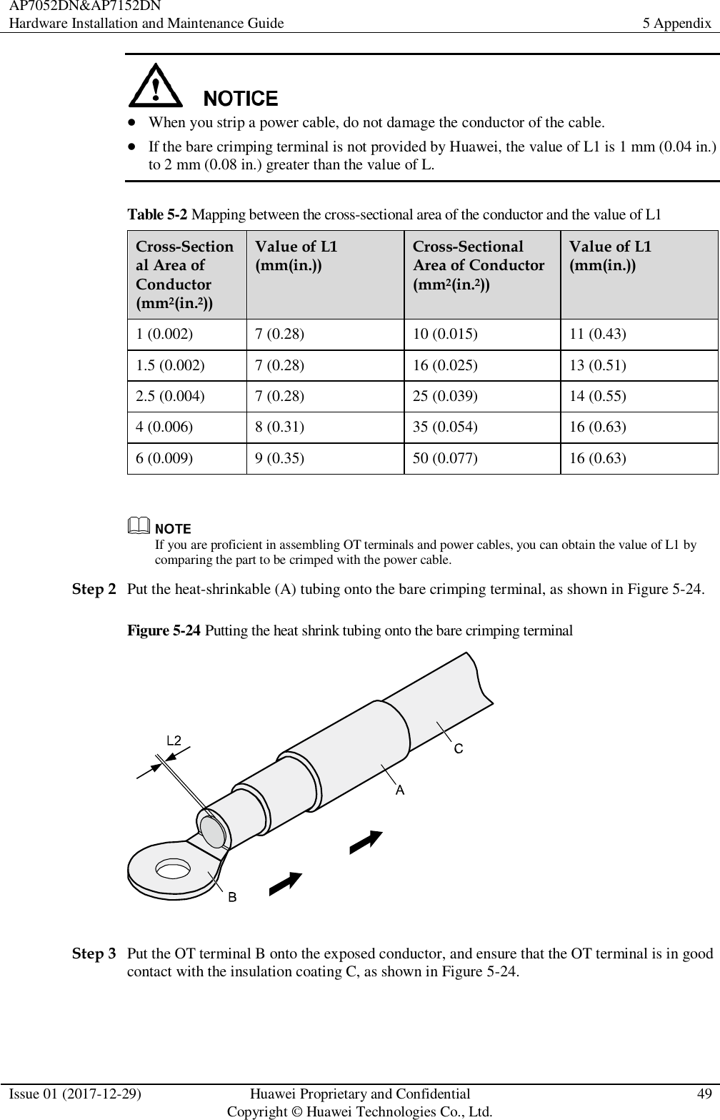
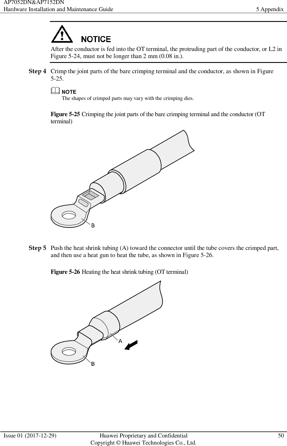
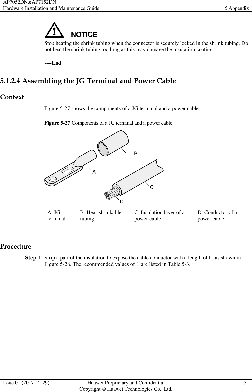
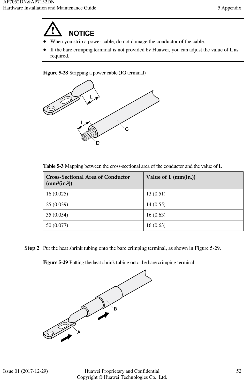
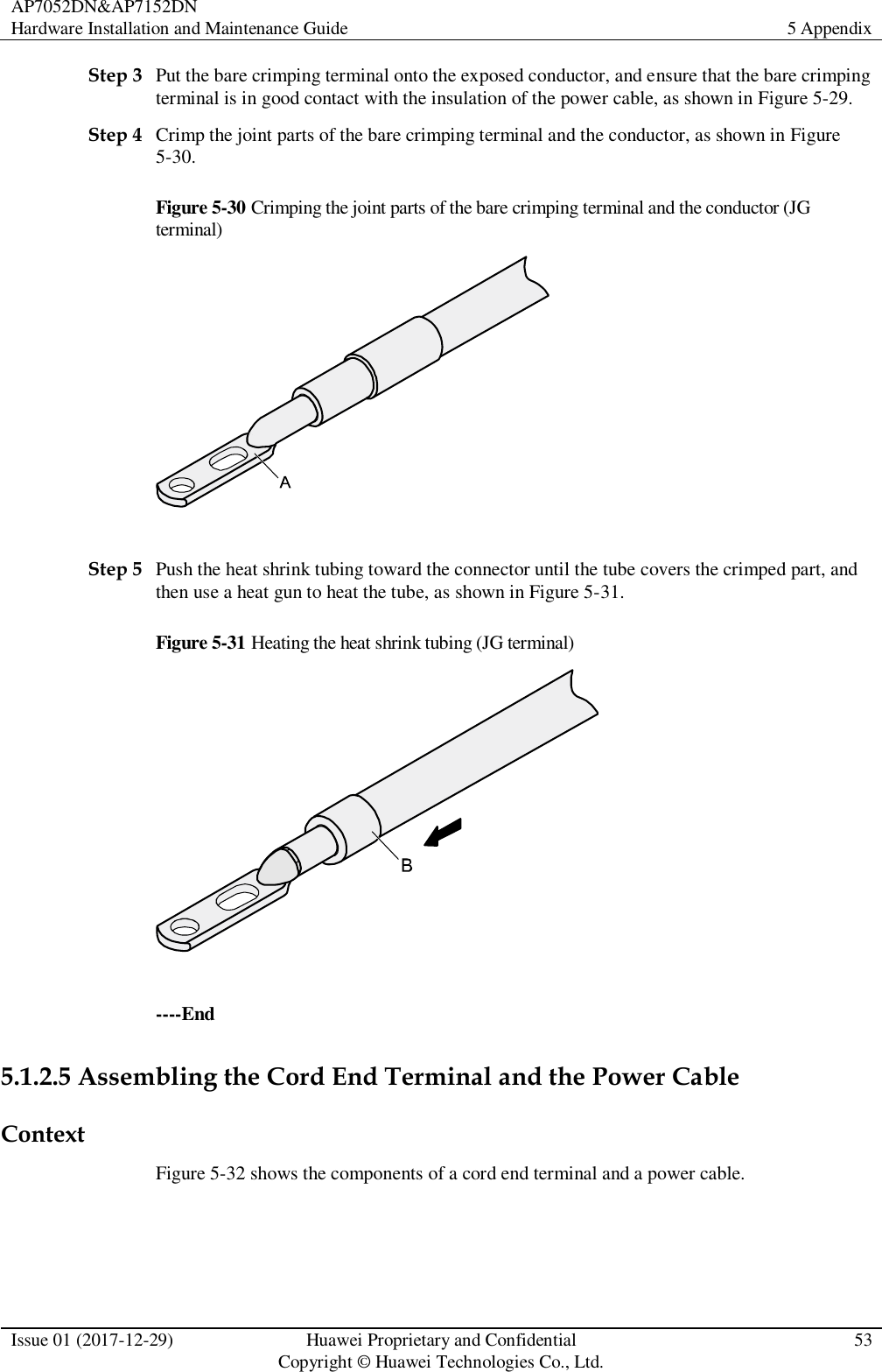
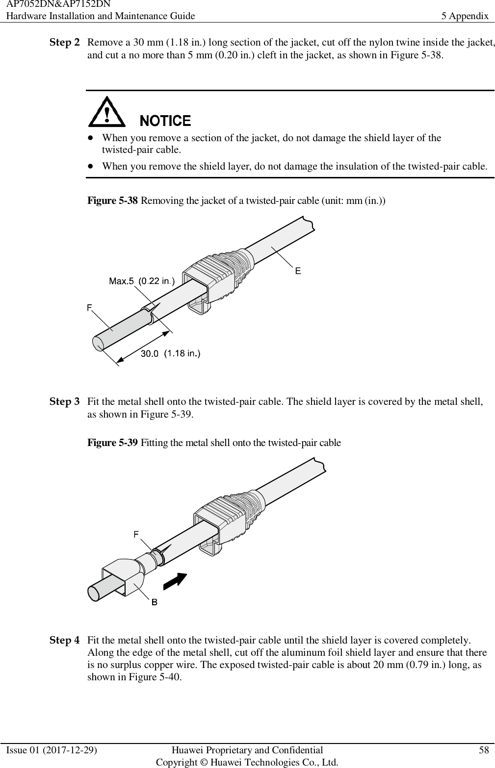
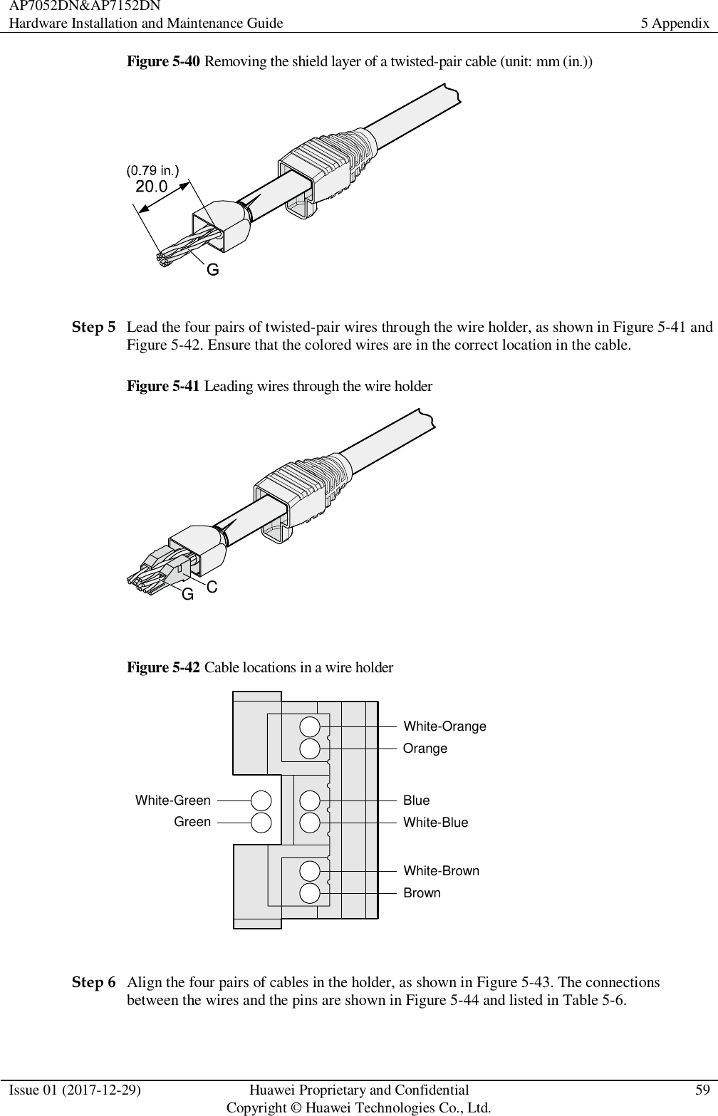
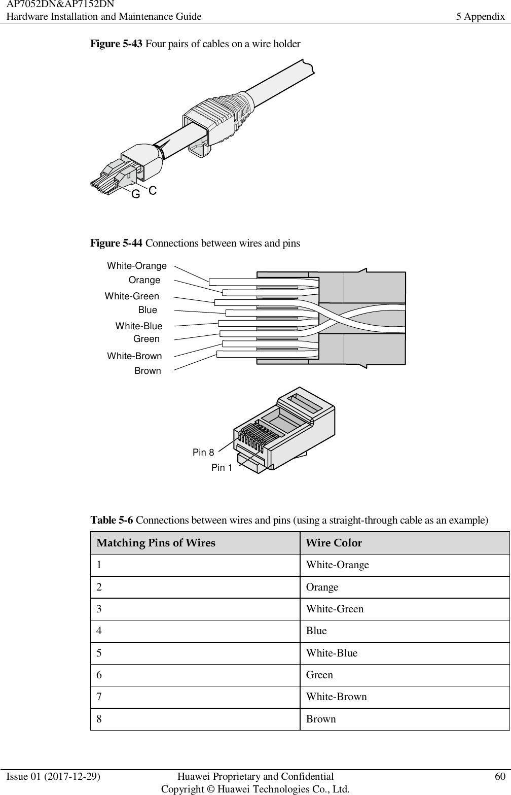
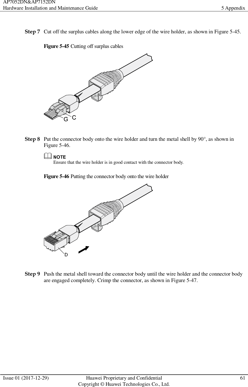
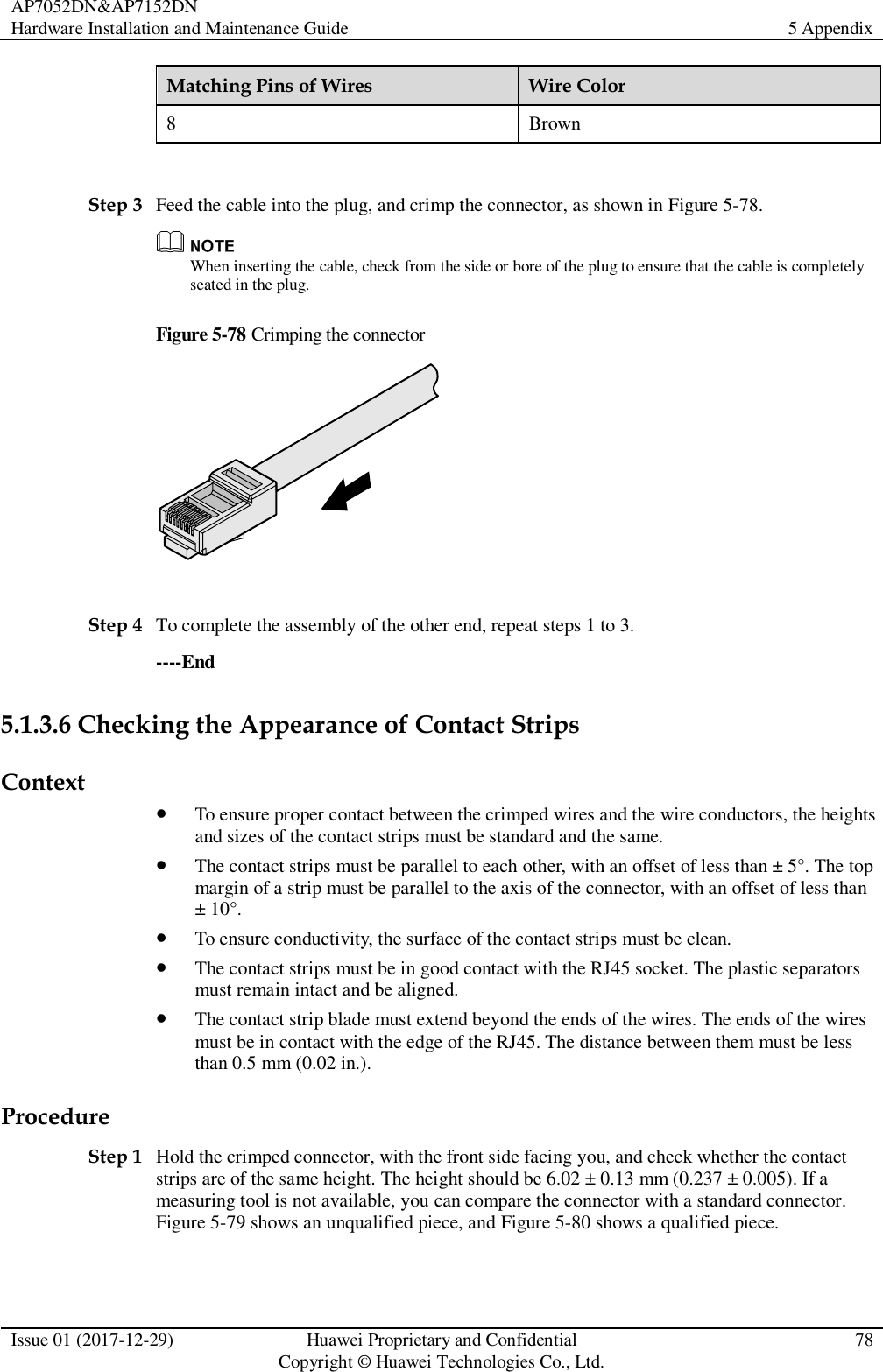
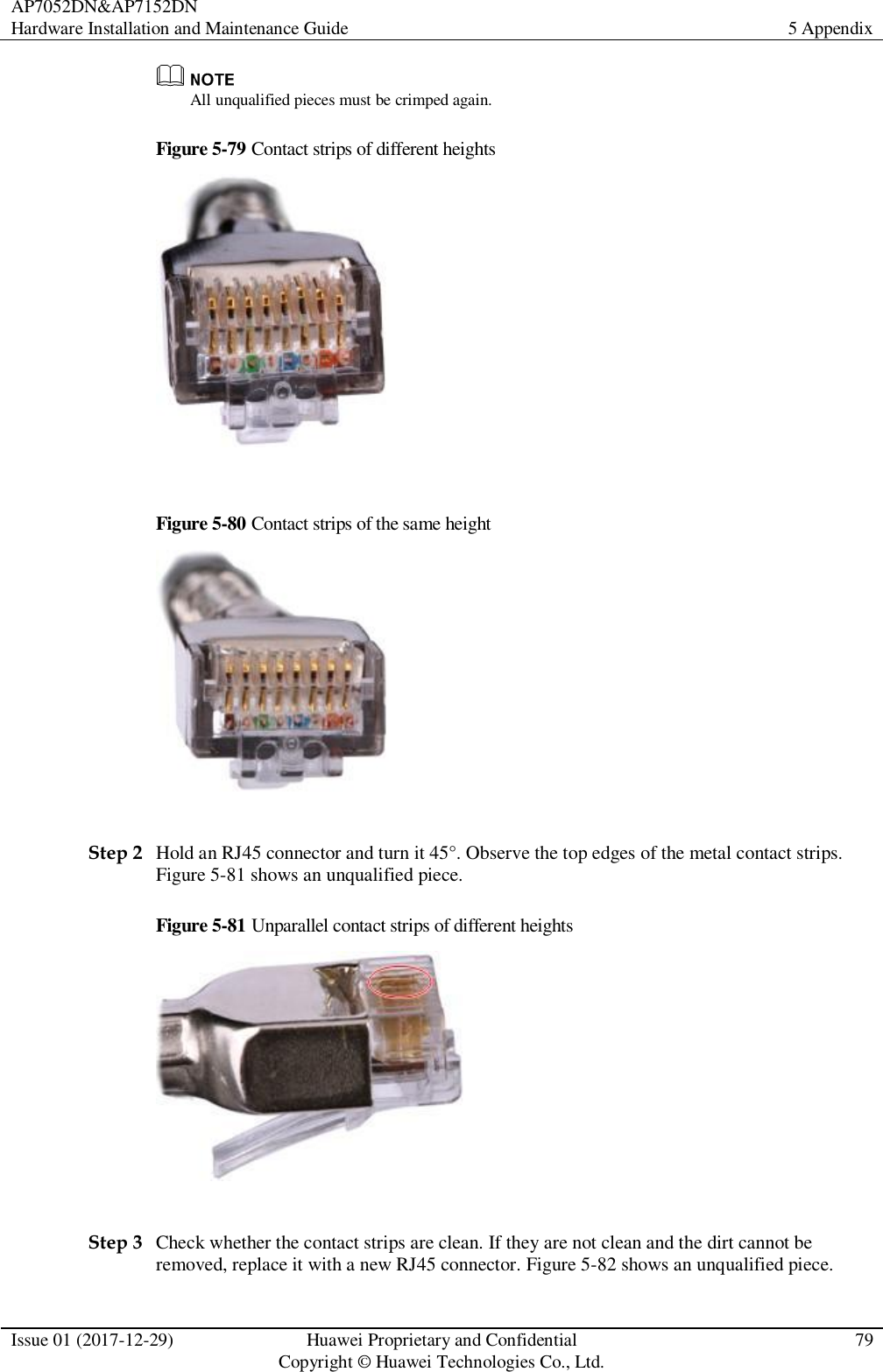
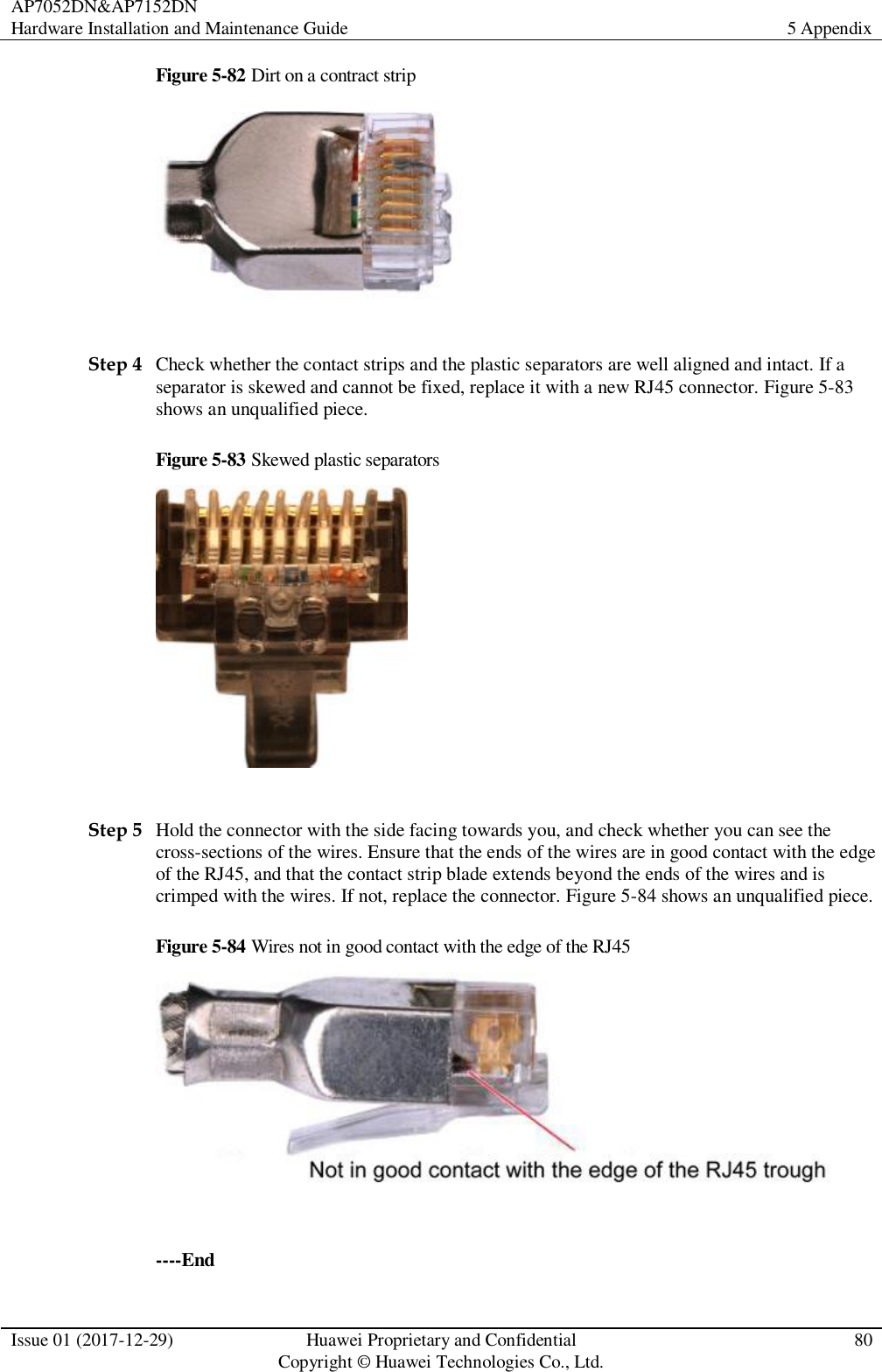
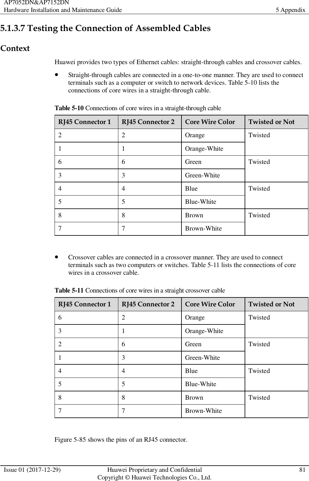
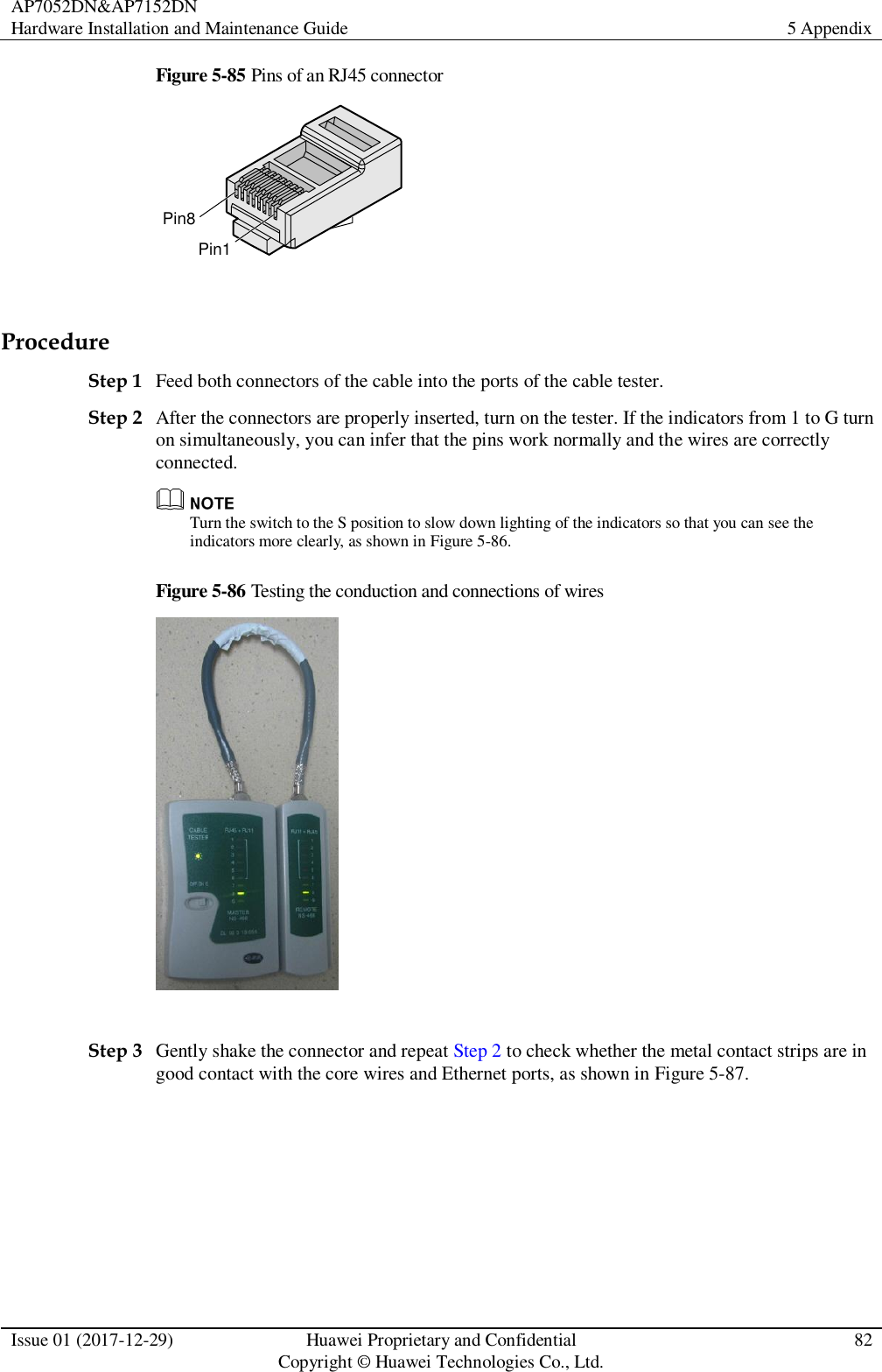
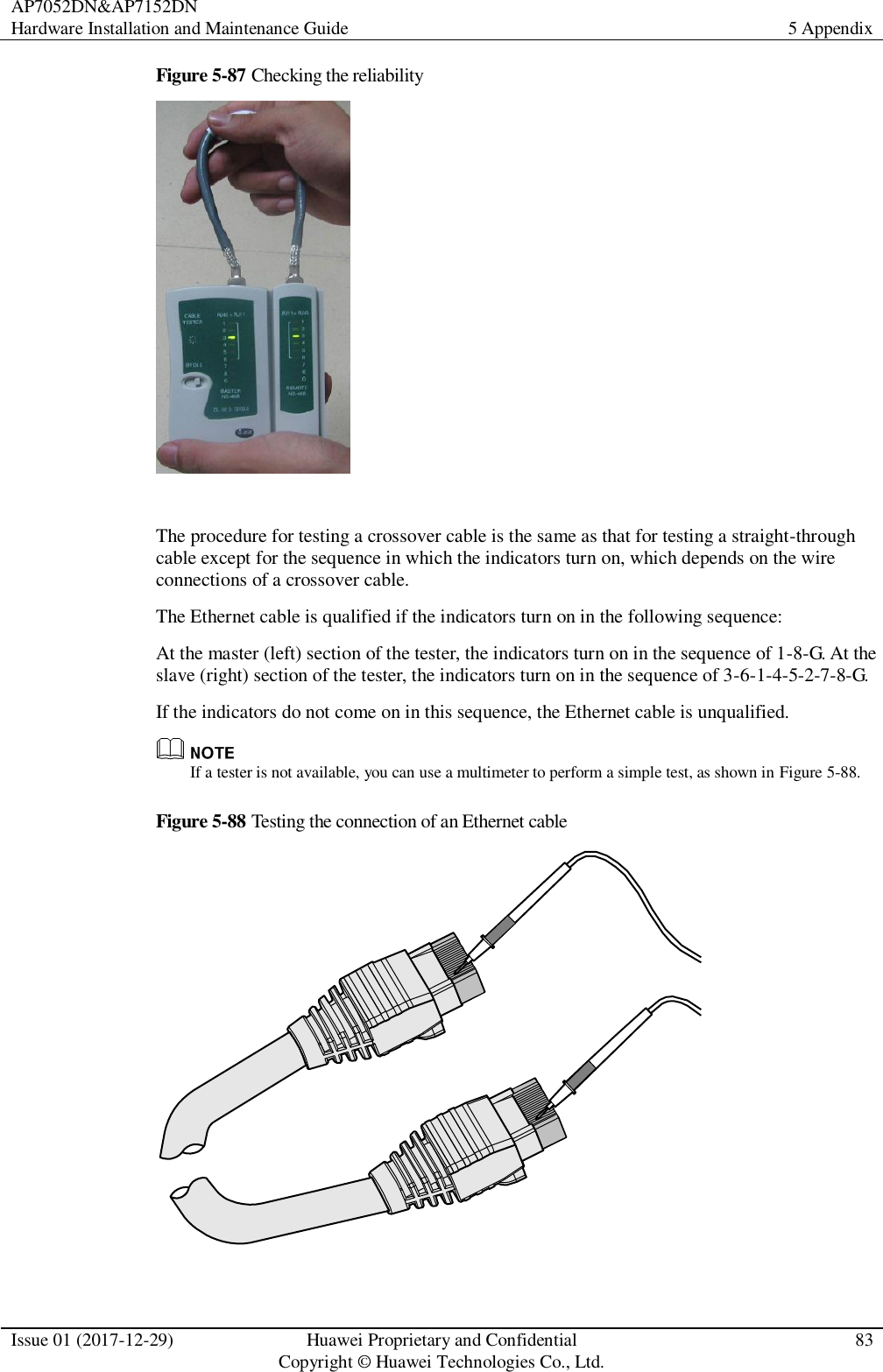
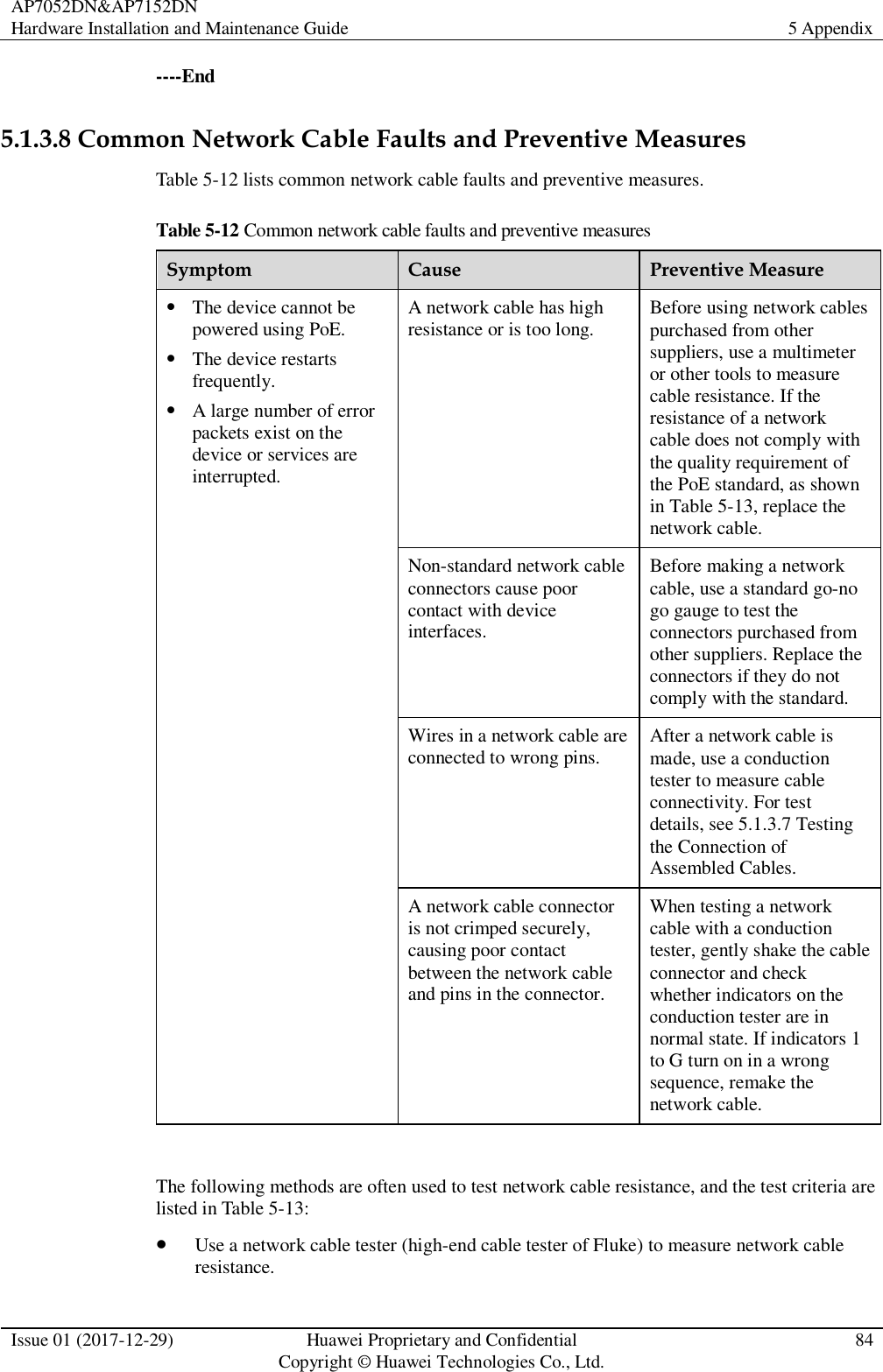
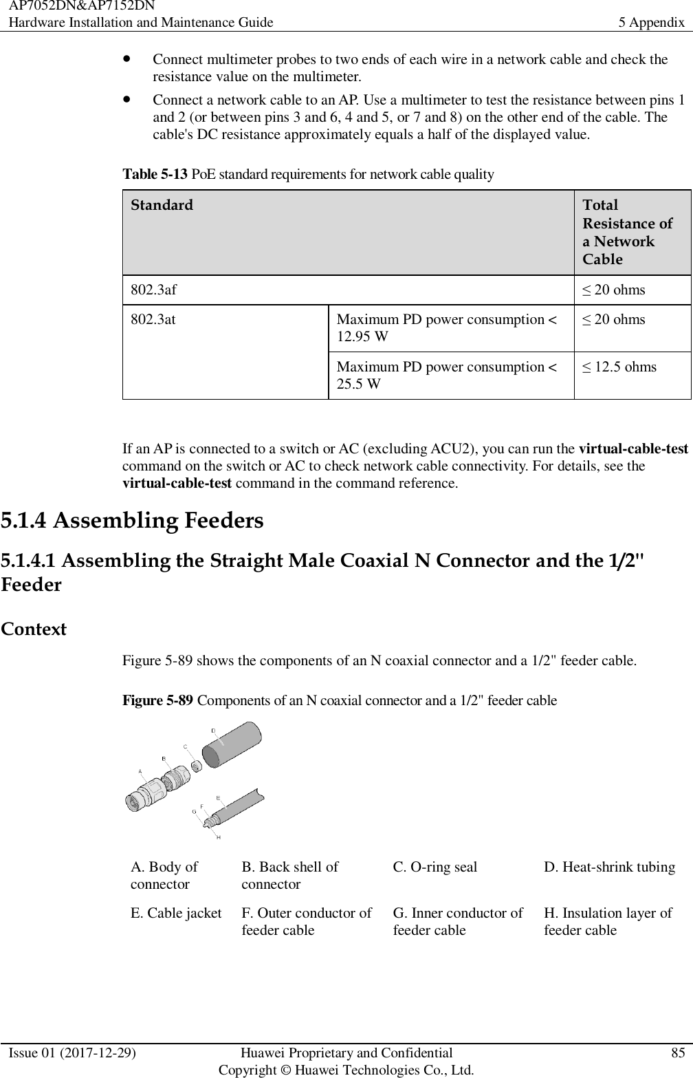
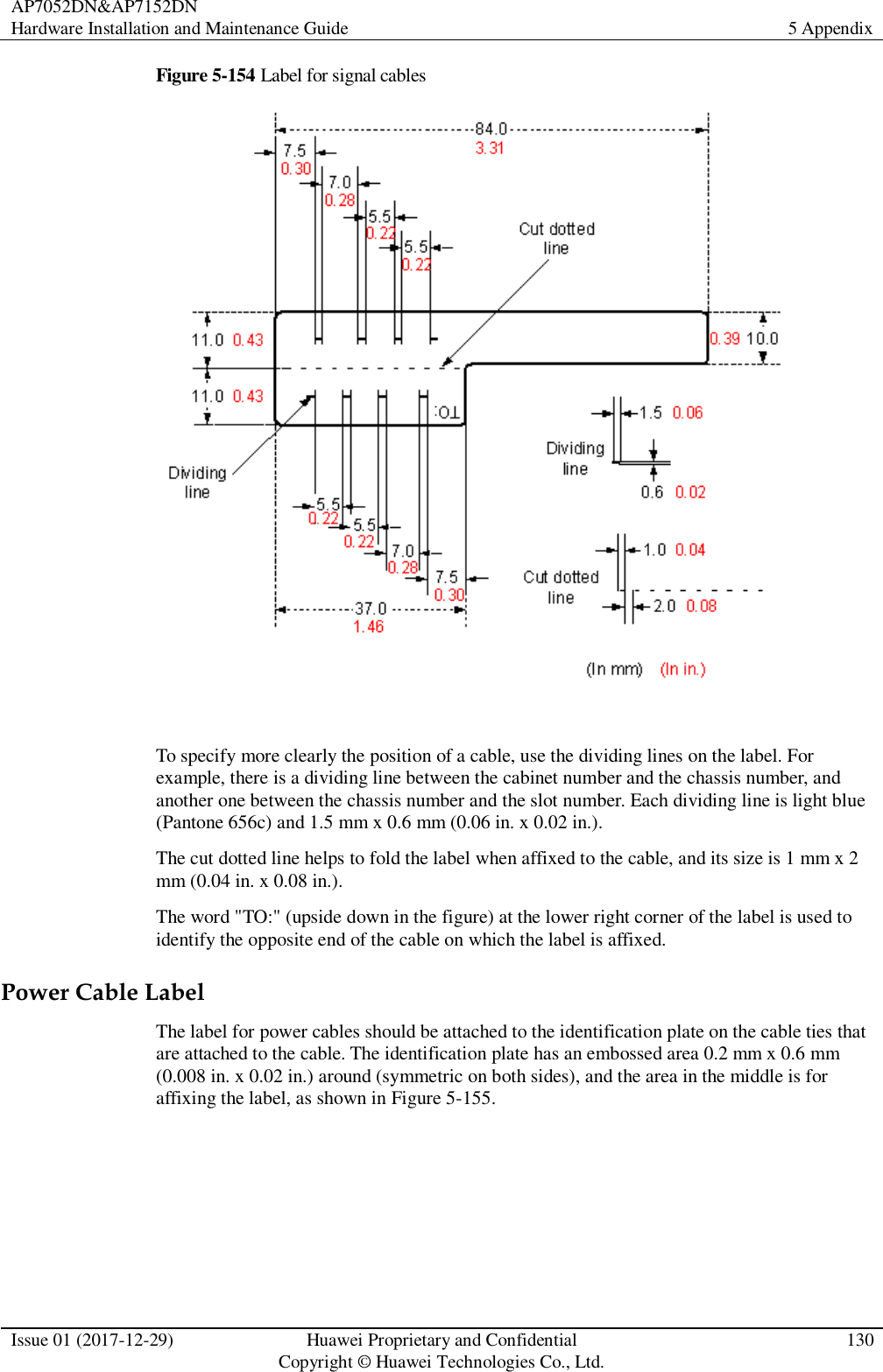
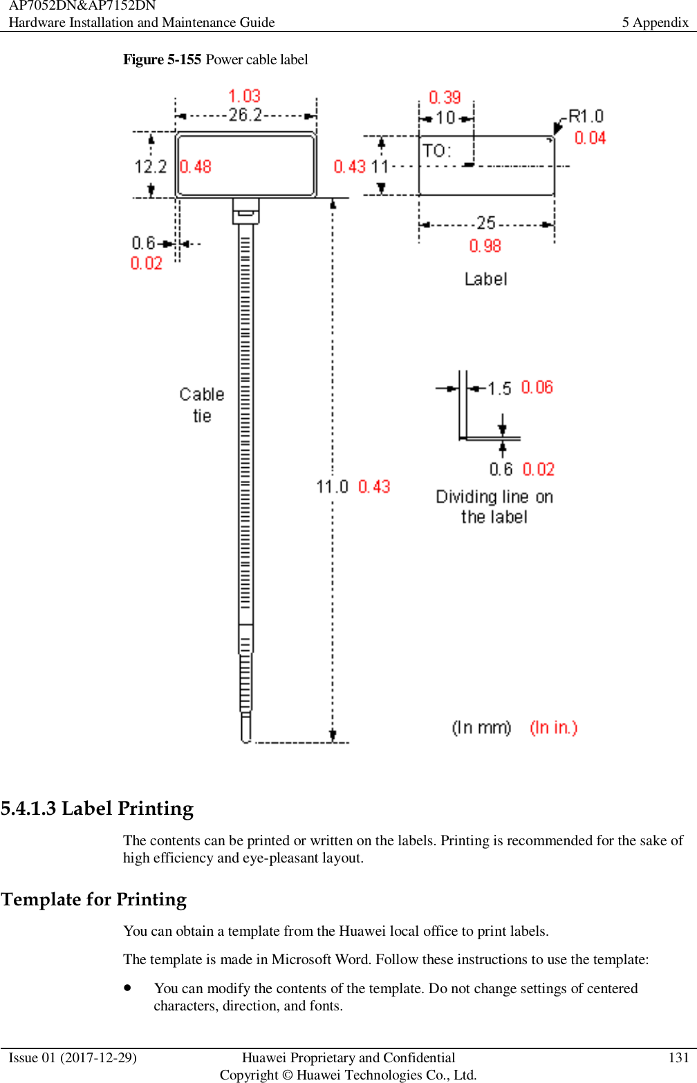
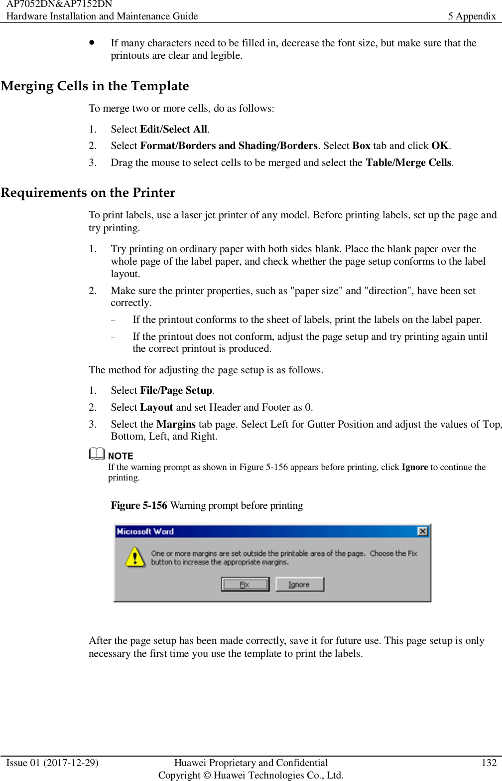
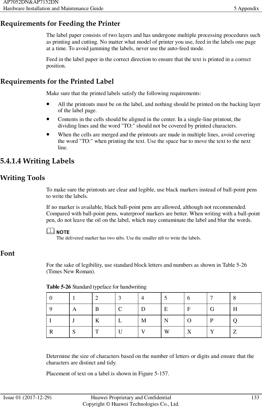
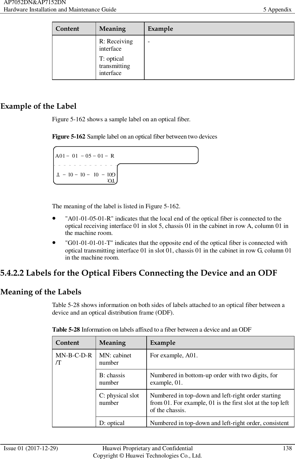
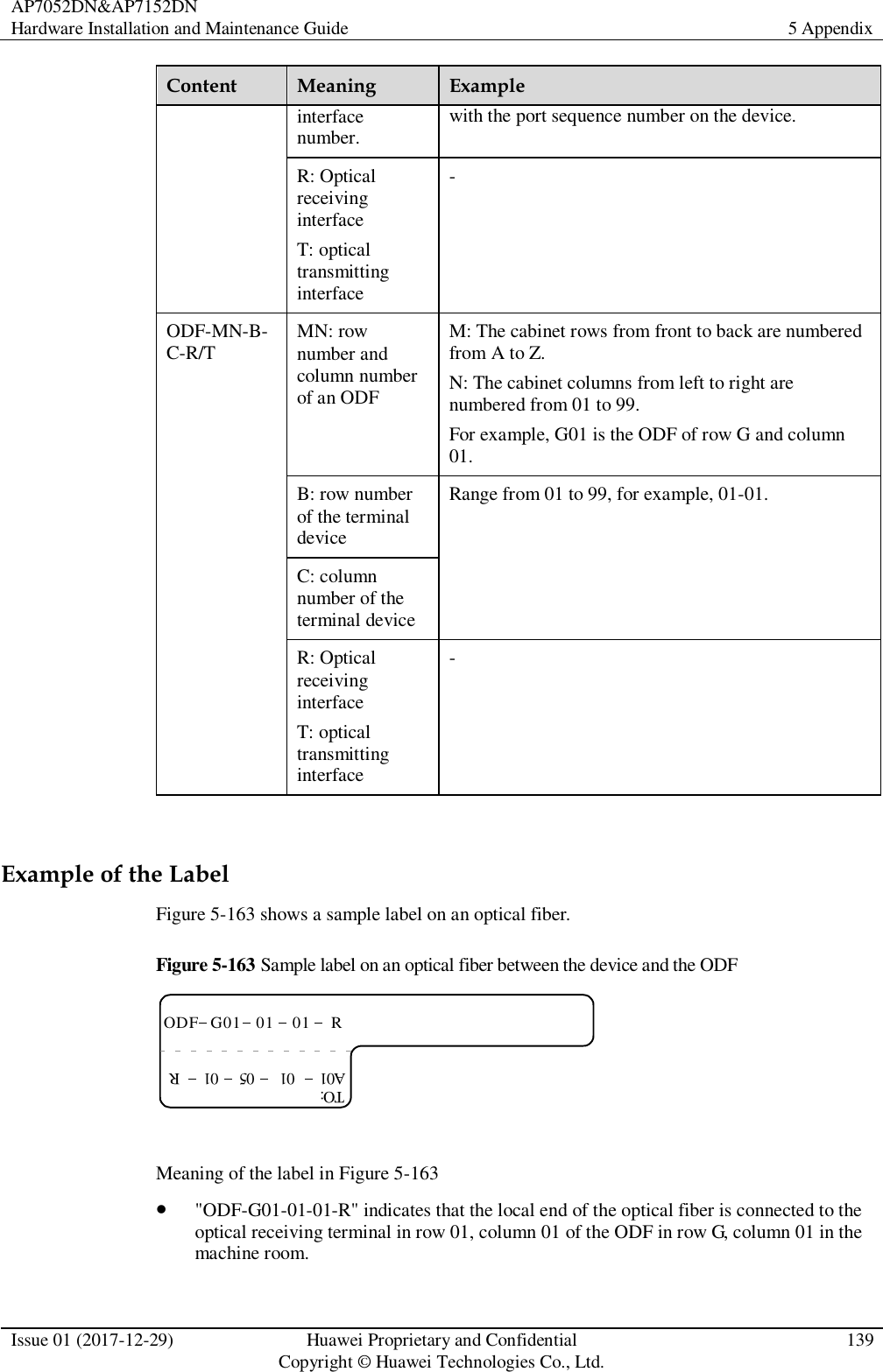
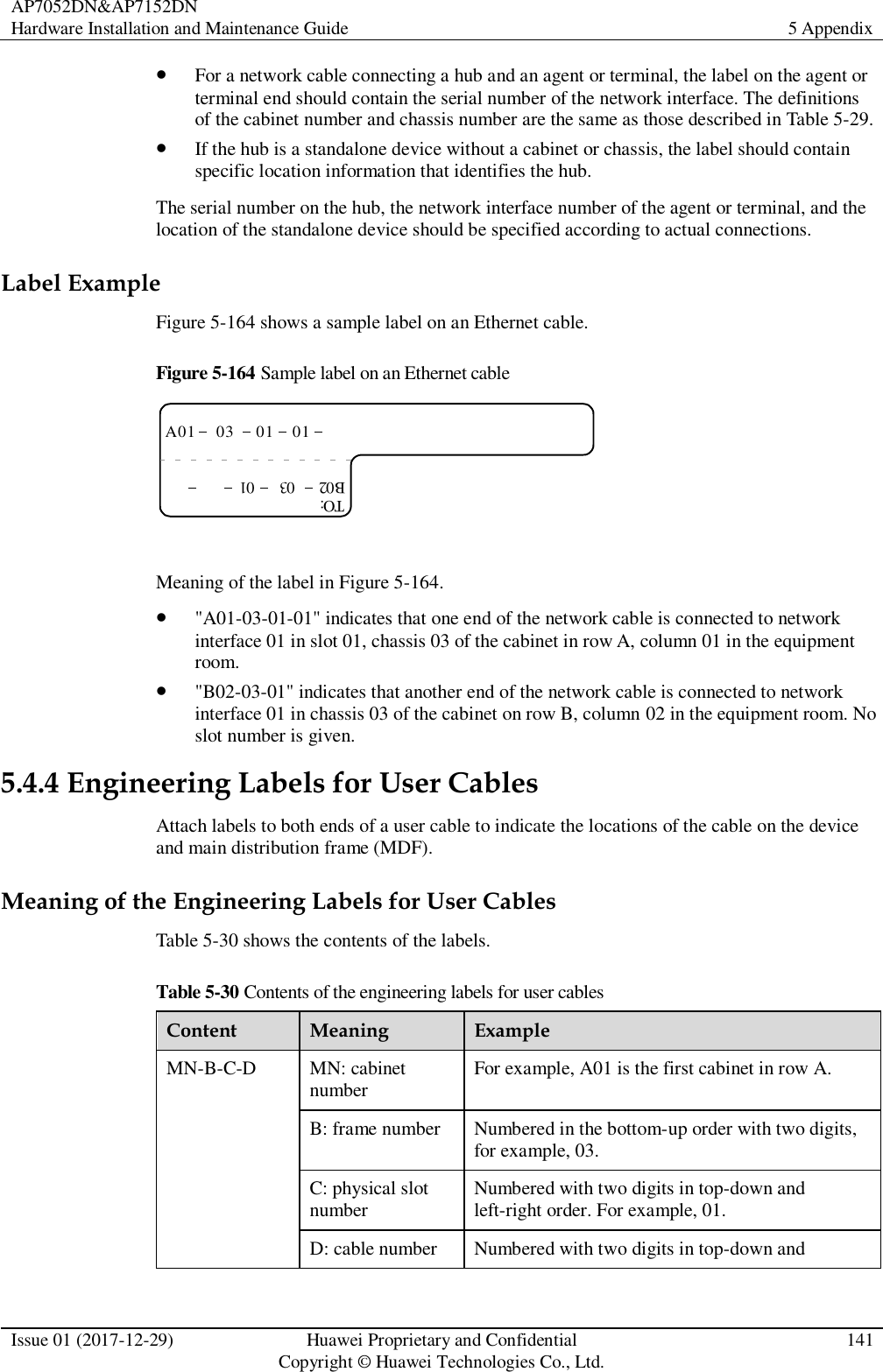
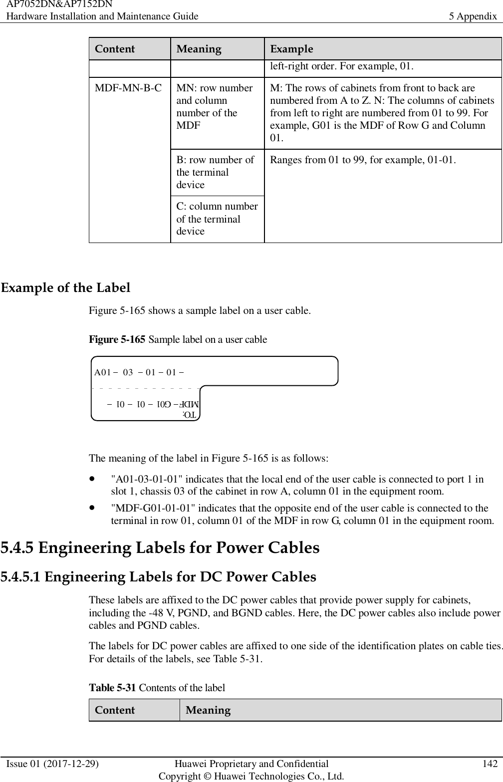
User guide