Huawei Technologies AR-SE-MC Access Router User Manual Part 1
Huawei Technologies Co.,Ltd Access Router Part 1
Contents
- 1. User Manual Part 1
- 2. User Manual Part 2
User Manual Part 1

Quick Start Guide
01 (2017-07-15) Part number: 31508106
AR-Sc&AR-Se&AR-Sa
&AR-So Series Elevator Gateways
Installation accessories:
LTE remote antenna (1) Quick Start Guide (1)
Packing List
Router (1, with product model on the nameplate)
The types and quantities of items in the installation accessory package vary
depending on the router configuration.
Appearance
1
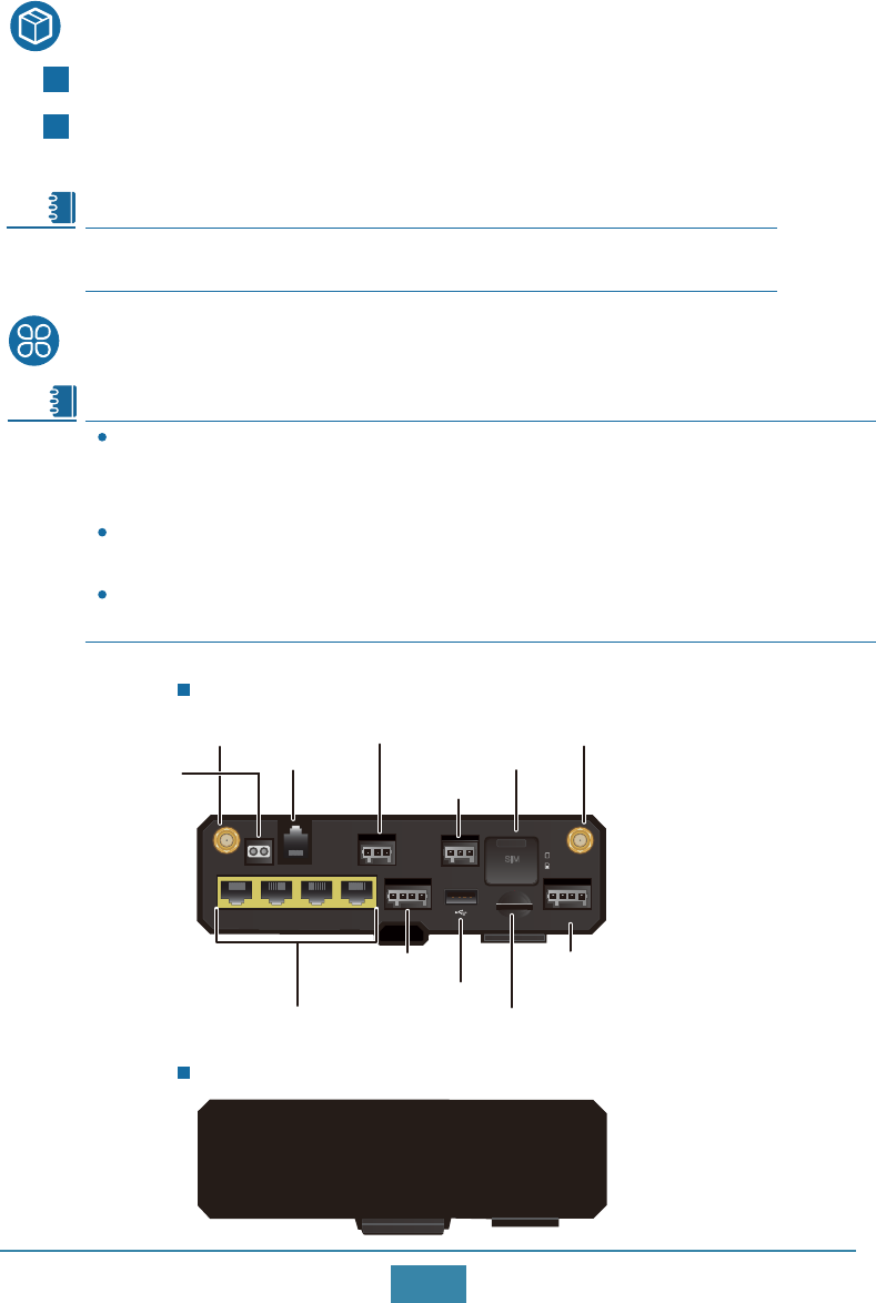
AR-Sc-Lc-BC (front view)
The AR-Sc-Lc-BC, AR-SC-U-BC, AR-Se-U-BC, AR-Se-L-BC, AR-Sa-U-BC, and
AR-Sa-La-BC routers are the same in appearance and indicators and only differ in
nameplates. AR-Sc-Lc-BC is used as an example here.
The AR-Sc-Lc-MC, AR-Se-L-MC, and AR-Sa-La-MC routers are the same in appearance
and indicators and only differ in nameplates. AR-Sc-Lc-MC is used as an example here.
The AR-Sc-MC and AR-Se-MC routers are the same in appearance and indicators and
only differ in nameplates. AR-Sc-MC is used as an example here.
AR-Sc-Lc-BC (rear view)
Note
Note
micro SD
SIM DIVMAIN 2
1
+ - TX RX
PWR
CANRS485RS232FXS
DI DO
Eth0/WAN Eth1 Eth2 Eth3
+ - + -
Four 100M electrical interfaces
USB interface
Primary LTE antenna interface Secondary LTE antenna interface
DI/DO interface
Micro SD card slot
Power socket
SIM card slot
CAN interface
RS485 interface
RS232 interface
FXS interface
2
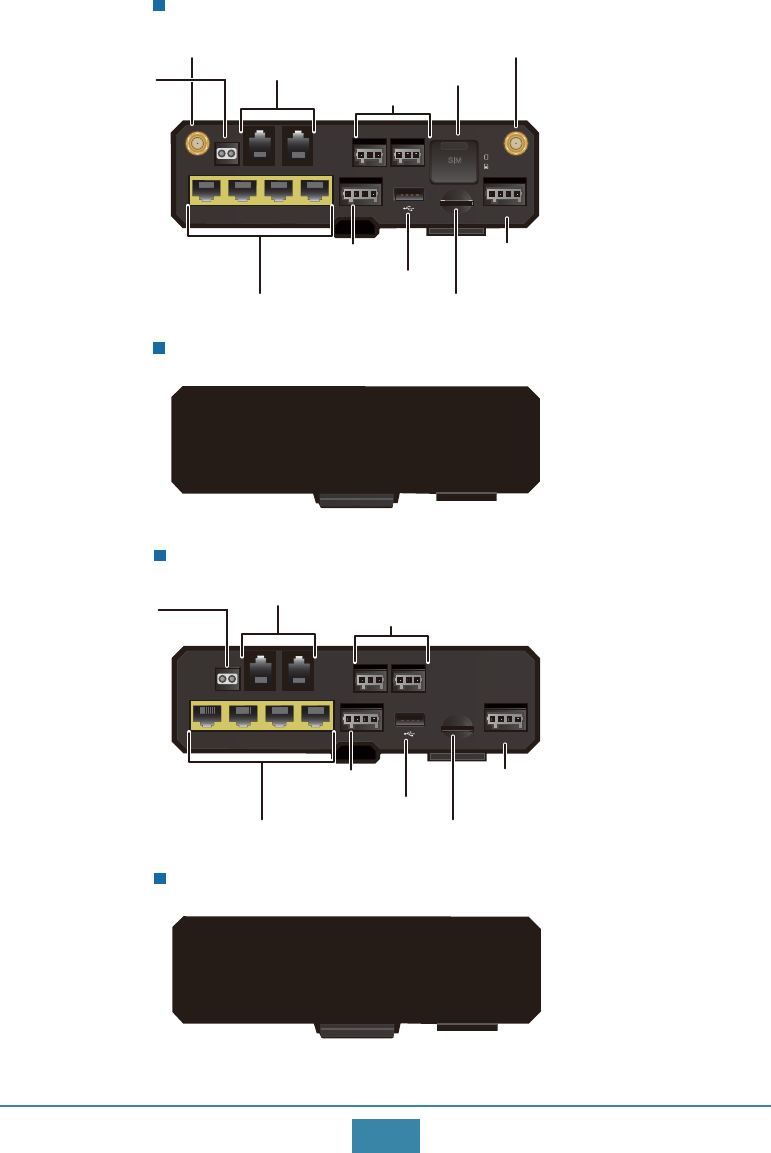
AR-Sc-Lc-MC (front view)
AR-Sc-Lc-MC (rear view)
AR-Sc-MC (front view)
AR-Sc-MC (rear view)
micro SD
SIM DIVMAIN 2
1
+ - TX RX
PWR
CAN-1CAN-0RS232-0 RS232-1FXS
DI DO
Eth0/WAN Eth1 Eth2 Eth3
+ - + -
Two CAN interfaces
Two RS232 interfaces SIM card slot
USB interface
DI/DO interface
Micro SD card slot
Power socket
Primary LTE antenna interface Secondary LTE antenna interface
FXS interface
Four 100M electrical interfaces
micro SD
+ - TX RX
PWR
CAN-1CAN-0RS232-0 RS232-1FXS
DI DO
Eth0/WAN Eth1 Eth2 Eth3
+ - + -
USB interface
DI/DO interface
Micro SD card slot
Power socket
FXS interface Two RS232 interfaces
Two CAN interfaces
Four 100M electrical interfaces
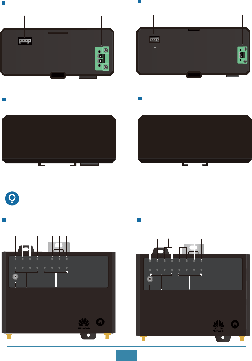
12V GND RX TX
OUTPUT: 12V;0.8A
INPUT:~100-240V;50/60Hz;0.8A
L/+
N/-
12V GND RX TX
OUTPUT: 12V;0.8A
INPUT:~100-240V;50/60Hz;0.8A
L
N
3
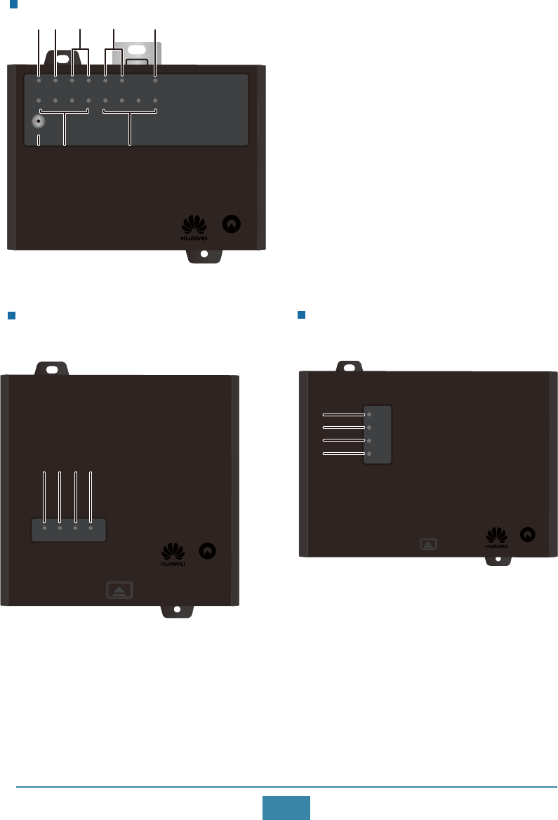
Indicator Description
Indicators of AR-Sc-Lc-MC
Indicators of AR-Sc-Lc-BC
Schindler
PWR FXS RS232 RS485 CAN SIGNAL DI
Eth0/WAN
BLE/RST
Eth1 Eth2 Eth3 CIL1 CIL2 CIL3 CIL4
1 2 3 4 5 6
8 79
10
Schindler
PWR FXS RS232-0 RS232-1 CAN-0 CAN-1 SIGNAL DI
Eth0/WAN
BLE/RST
Eth1 Eth2 Eth3 CIL1 CIL2 CIL3 CIL4
12 3 4 5 6
8 79
AR-PM1 (front view)
AR-PM1 (rear view)
AR-PM4 (front view)
AR-PM4 (rear view)
InputOutput InputOutput
4
Indicators of AR-Sc-MC
Schindler
PWR FXS RS232-0 RS232-1 CAN-0 CAN-1 DI
Eth0/WAN
BLE/RST
Eth1 Eth2 Eth3 CIL1 CIL2 CIL3 CIL4
12 3 4 6
8 79
Indicators of AR-PM4
Indicators of AR-PM1
Schindler
SYS DC/BAT RS232 STA
11 12 1314
Schindler
SYS
DC/BAT
RS232
STA
11
12
13
14

FXS2
Steady green: The power supply to the router is normal.
Off: The router receives no power supply.
PWR
1
Number Indicator Description
RS2323
CAN4
Steady green: The FXS channel is idle.
Blinking green: There is an ongoing call on the FXS channel.
Off: The FXS channel is occupied.
Indicator states can be user defined.
5
6
SIGNAL
Eth(Eth0/WAN~Eth3)
Steady green: A link has been established on the corresponding
interface.
Blinking green: Data is being transmitted on the corresponding
link.
Of: No link is established on the corresponding interface.
7CIL(CIL1~CIL4)
DI
8
9 BLE/RST
Press once to
enable Bluetooth
10 RS485
5
CL1 CL2 CL3 CL4
Press twice to
reset the router
Press 3 times to
restore factory
settings
Fast blink Steady on
Indicator states can be user defined.
Indicator states can be user defined.
Indicator states can be user defined.
Indicator states can be user defined.
Fast blink Fast blink
Steady on
Steady on
Steady on
Steady onSteady on
Fast blink Fast blink
Fast blink
Indicator states can be user defined.
11 SYS
Steady green: The UPS is starting.
Blinking green: The UPS has started successfully.
Off: The UPS has not started.
12 DC/BAT
Steady green: The power module of the router is working.
Blinking green: The UPS is working.
Off: The UPS is not working.
13 RS232 Steady green: The router is connected to the UPS.
Off: The router is not connected to the UPS.
14 STA
Steady green: The battery of the UPS is working normally.
Fast blinking green: The batter of the UPS can provide power
supply for less than 1 hour (4 hours).
Slow blinking green: The battery of the UPS has failed or run
out of power.
Off: The UPS is not working.
6
Installing the Router
Before the installation, ensure the following:
Sufficient space has been reserved for the router.
The DIN rail has been fixed.
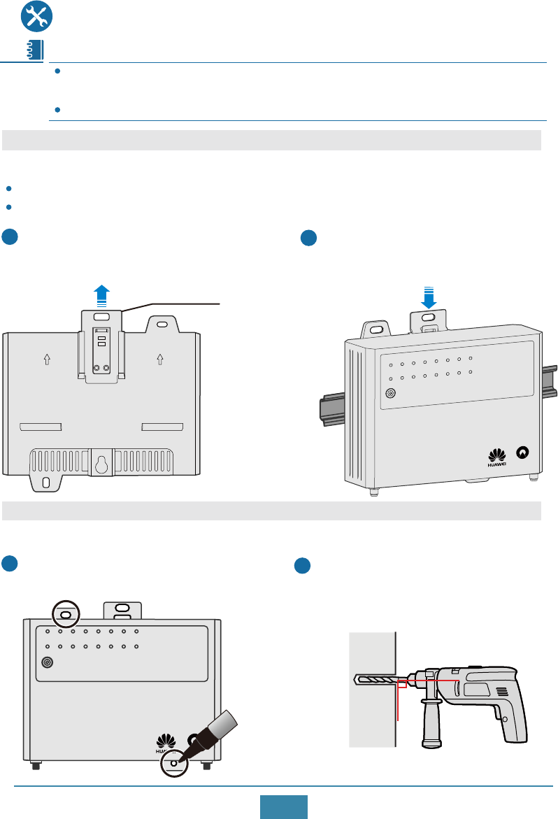
Pull the fixture on the DIN rail mounting
kit at the back of the router.
1
Place the DIN rail mounting kit onto
the DIN rail and press the fixture to
secure the router on the DIN rail.
2
Scenario 1: Installing the Router on a DIN Rail
Fixture
Scenario 2: Mounting the Router on a Wall
Mark the positions of two mounting
holes on the wall.
1
Installation Method 1
Drill holes for ST4.2 tapping screws on
the wall using a hammer drill with an
appropriate drill bit.
2
The methods for installing, connoting and logging in to the AR-Sc, AR-Se, AR-Sa, AR-So
series routers and AR-PM series UPS are similar. AR-Sc-Lc-MC is used as an example here.
AR-PM series UPS cannot be mounted on a Wall.
Note
Schindler
PWR FXS RS232-0 RS232-1 CAN-0 CAN-1 SIGNAL DI
Eth0/WAN
BLE/RST
Eth1 Eth2 Eth3 CIL1 CIL2 CIL3 CIL4
Schindler
PWR FXS RS232-0 RS232-1 CAN-0 CAN-1 SIGNAL DI
Eth0/WAN
BLE/RST
Eth1 Eth2 Eth3 CIL1 CIL2 CIL3 CIL4
90°
7
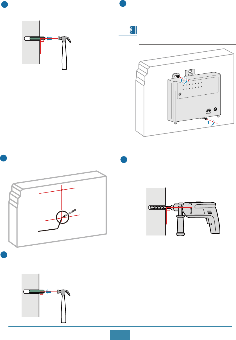
The torque for an ST4.2 screw is 0.8 N·m.
Hammer hollow wall anchors
into the mounting holes.
3
90°
Hold the bottom of the router and
fix it on the wall with two ST4.2
tapping screws.
4
Installation Method 2
Mark the positions of two mounting
holes on the wall.
1
Drill holes for ST4.2 tapping screws on
the wall using a hammer drill with an
appropriate drill bit.
2
Hammer hollow wall anchors
into the mounting holes.
3
90°
Note
Schindler
PWR FXS RS232-0 RS232-1 CAN-0 CAN-1 SIGNAL DI
Eth0/WAN
BLE/RST
Eth1 Eth2 Eth3 CIL1 CIL2 CIL3 CIL4
105.3mm
pre-mounting hole
90°
8
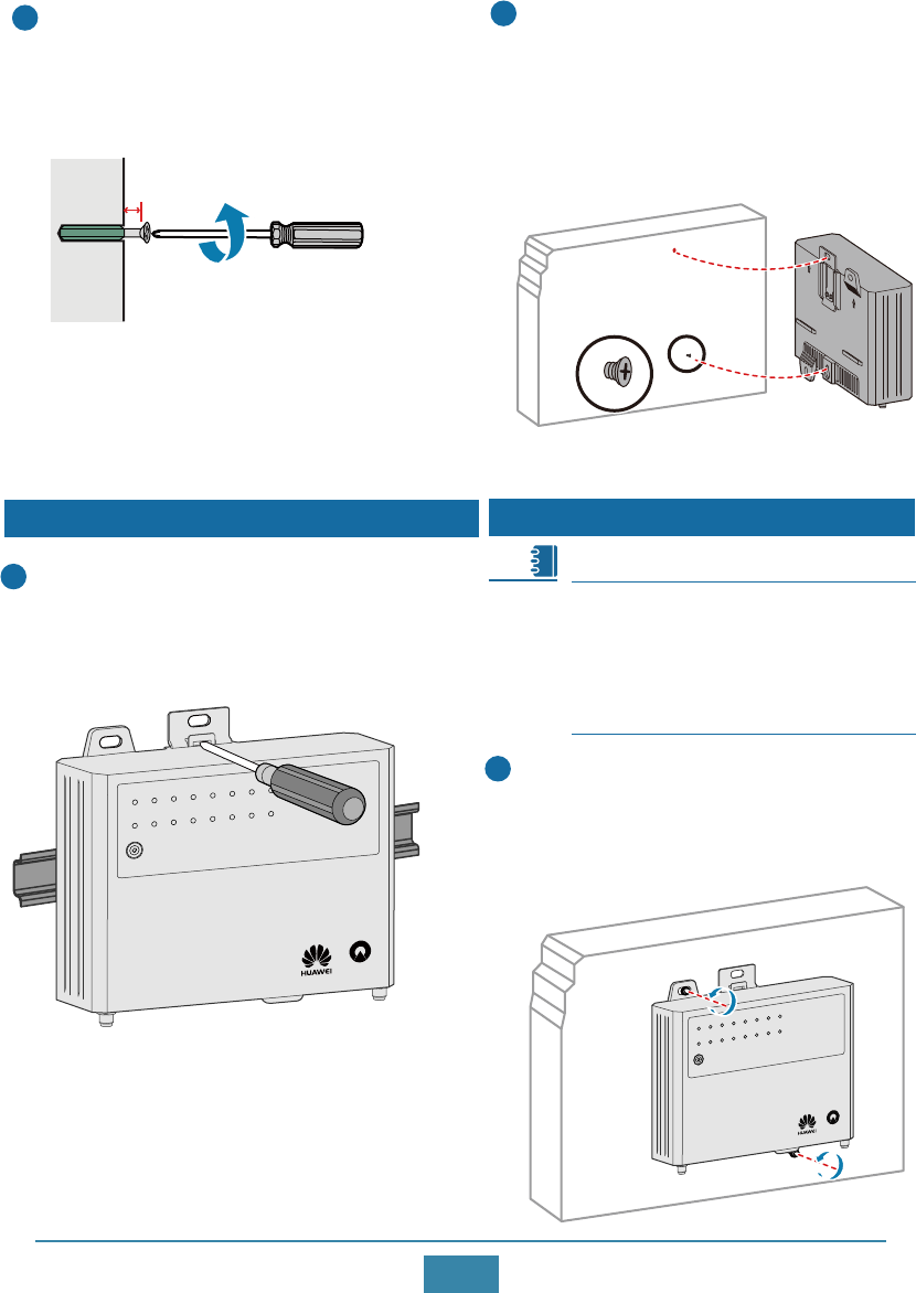
Removing the Router from the Wall
Hold the bottom of the router, use a
Phillips screwdriver to loosen the
tapping screws, and then remove the
router from the wall.
1
The router is removed in the same way
regardless of whether it has been
installed using method 1 or 2. In this
example, the router is installed using
method 1.
Use a Phillips screwdriver to screw an
ST4.2 tapping screw into the
pre-mounting hole. Leave 4 mm length
of the screw out of the wall.
4
Hang the router on the tapping
screw through the pre-mounting
hole at the back. Hold the bottom
of the router and use another ST4.2
tapping screw to secure the router
on the wall.
5
Removing the Router from the DIN Rail
Use a flat-head screwdriver to press the
metal plate on the DIN rail mounting kit,
remove the fixture, and then remove the
router from the DIN rail.
1
Note
Schindler
PWR FXS RS232-0 RS232-1 CAN-0 CAN-1 SIGNAL DI
Eth0/WAN
BLE/RST
Eth1 Eth2 Eth3 CIL1 CIL2 CIL3 CIL4
Schindler
PWR FXS RS232-0 RS232-1 CAN-0 CAN-1 SIGNAL DI
Eth0/WAN
BLE/RST
Eth1 Eth2 Eth3 CIL1 CIL2 CIL3 CIL4
4mm
9
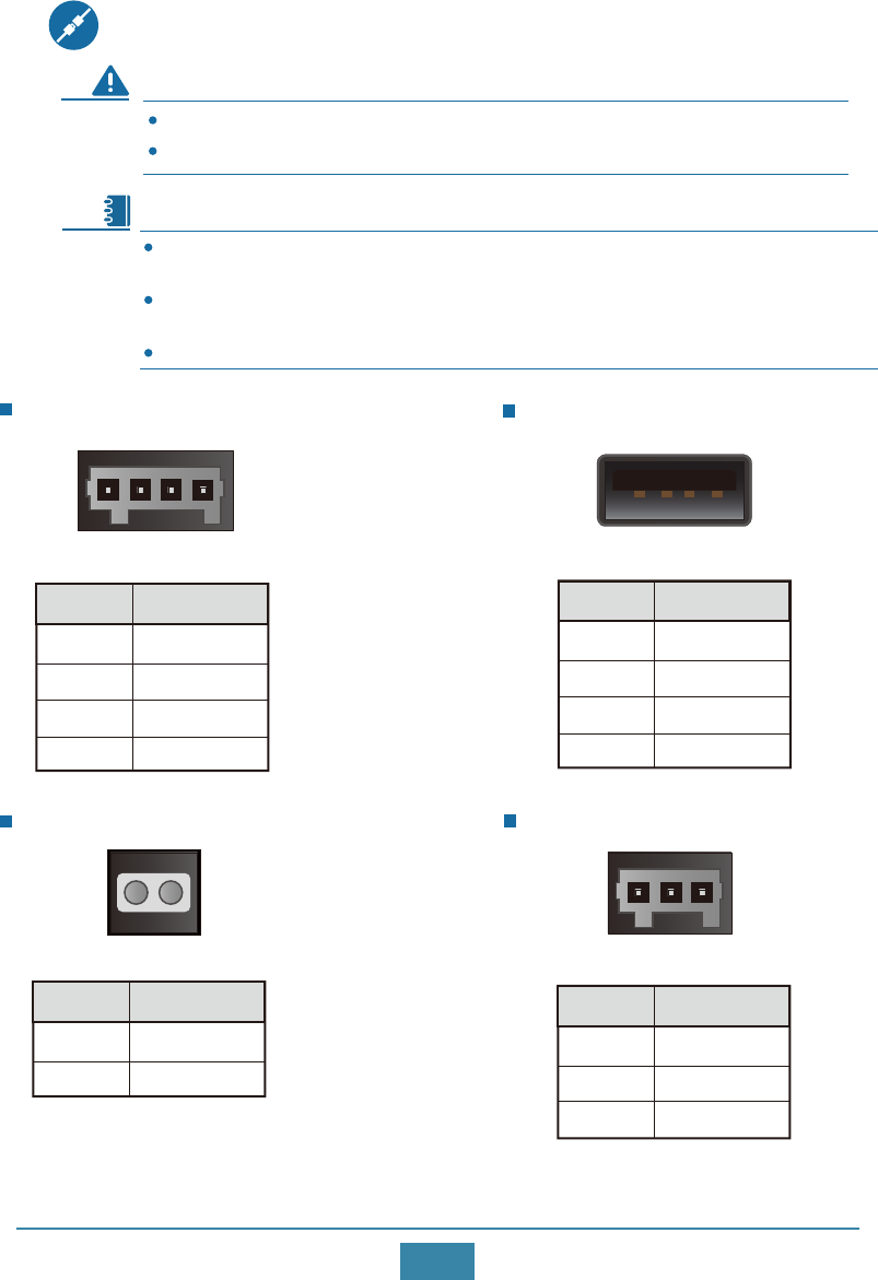
Connecting the Router
WARNING To avoid electric shock, do not connect power cables while the power is on.
Do not power on the router before you finish connecting and arranging cables.
An LTE remote antenna is delivered with the router. Connect it to the LTE MAIN
interface of the router.
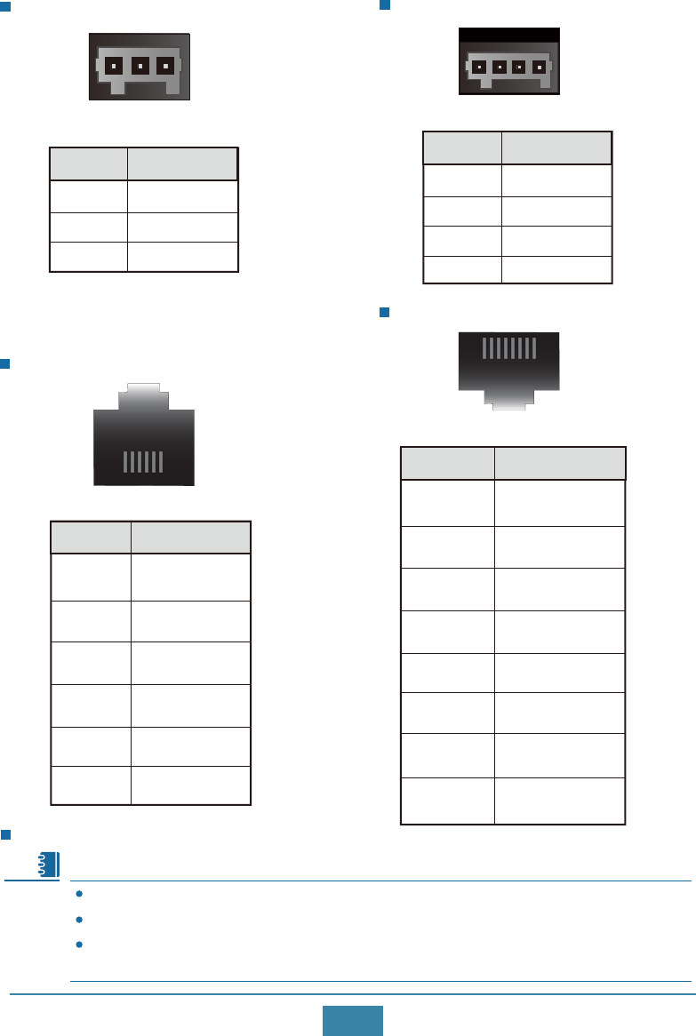
For other interfaces, make cables onsite using self-provided terminals. The following
tables provide pin assignments of different interfaces.
The FXS interface cannot connect to a PSTN network and is only used for internal.
Power socket pin assignments USB interface pin assignments
RS485 interface pin assignments
Note
2
+
1
Pin
3
4
-
TX
RX
Signal Type
2
1
3
4
VBUS
D-
D+
GND
Pin Signal Type
2
1
3
RS485 a
RS485 b
C_GND
Pin Signal Type
FXS interface pin assignments
2
1a
b
Pin Signal Type
1 2
1 4
1 4
13
10
CAN interface pin assignments
Eth interface pin assignments
2
1
3
CAN_L
CAN_H
NC
Pin Signal Type
RS232 interface pin assignments
2
COM1
3
4
RX
TX
NC
5
6
RTS
CTS
2
TX+1
3
4
TX-
RX+
NC
5
6RX-
7
8
NC
NC
NC
DI/DO interface pin assignments
2
1
3
4
DI+
DI-
DO+
DO-
Pin Signal Type
Pin Signal Type
Pin Signal Type
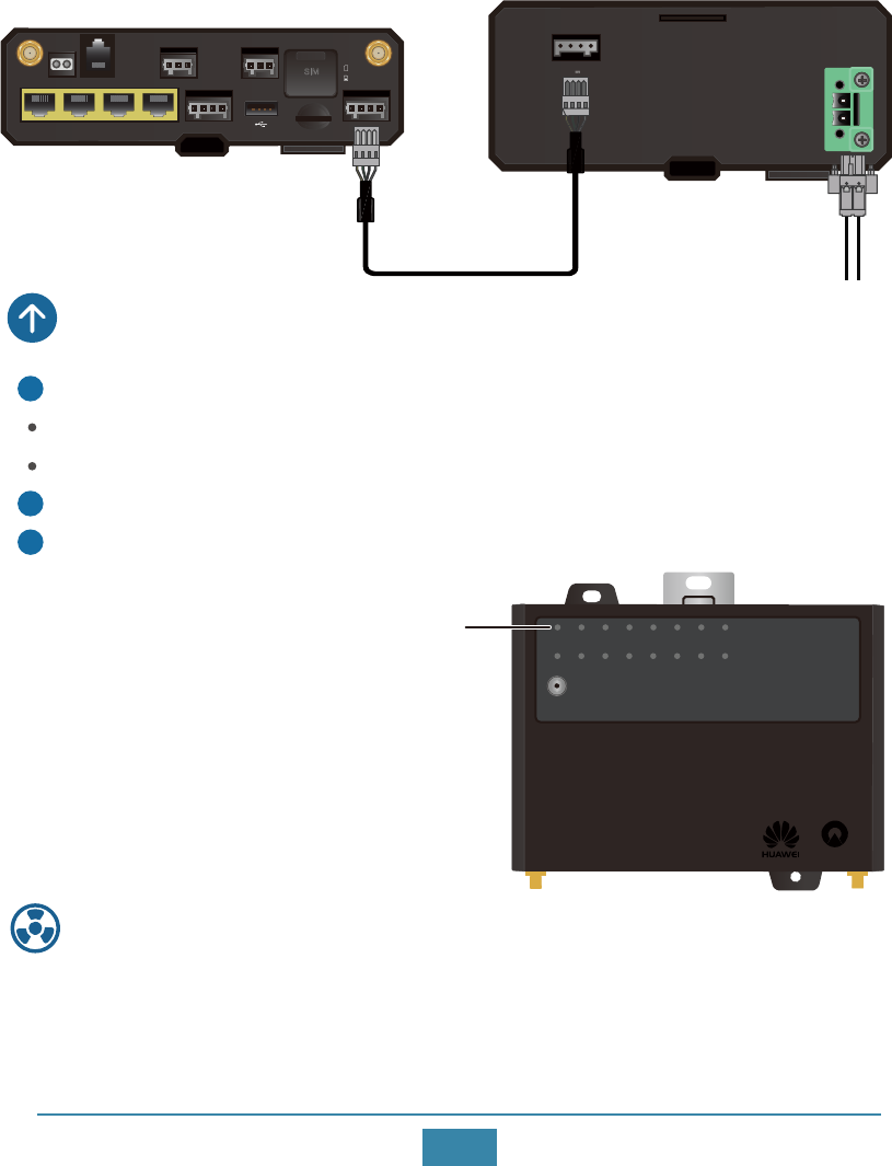
Connecting the Router to a UPS
The AR-Sc and AR-Se series routers support AR-PM1 UPS power supplies.
The AR-Se-MC, AR-So and AR-Sa series routers support AR-PM4 UPS power supplies.
The routers are connected to a UPS in the same way. The following example connects an
AR-Sc-Lc-BC router to an AR-PM1 UPS.
Note
131 4
1 6
1 8
12V GND RX TX
OUTPUT: 12V;0.8A
INPUT:~100-240V;50/60Hz;0.8A
L
N
Schindler
PWR FXS RS232-0 RS232-1 CAN-0 CAN-1 SIGNAL DI
Eth0/WAN
BLE/RST
Eth1 Eth2 Eth3 CIL1 CIL2 CIL3 CIL4
Powering On the Router
Before you power on the router, ensure the following:
The power cable has been properly connected.
The input voltage is within the normal range (12 V DC to 24 V DC).
Turn on the power switch of the external power supply system.
Check the PWR indicator on the front panel of the router.
1
2
3
PWR Steady green: The system power
supply is normal.
11
Hereby, Huawei Technologies Co., Ltd. declares that the radio equipment type
is in compliance with Directive 2014/53/EU.
The full text of the EU declaration of conformity is available at the following
internet address: www.huawei.com/en/product-certification.
Declaration of Conformity
Power output cable: delivered with the UPS.
Power input cable: made onsite using the 2-pin terminal block delivered with the UPS.
The diameter of the cable must be 16-22 AWG.
micro SD
SIM DIVMAIN 2
1
+ - TX RX
PWR
CANRS485RS232FXS
DI DO
Eth0/WAN Eth1 Eth2 Eth3
+ - + -
Power output cable External power source