Huawei Technologies BTS3606-1900D CDMA Base Station User Manual
Huawei Technologies Co.,Ltd CDMA Base Station Users Manual
Users Manual
Huawei Technologies Proprietary
HUAWEI
Airbridge BTS3606&3606A CDMA Base Station
Installation Manual – BTS3606 Cabinet Installation
V200R001

Huawei Technologies Proprietary
Airbridge BTS3606&3606A CDMA Base Station
Installation Manual
Volume BTS3606 Cabinet Installation
Manual Version T2-030451-20050202-C-2.11
Product Version V200R001
BOM 31041451
Huawei Technologies Co., Ltd. provides customers with comprehensive technical support
and service. Please feel free to contact our local office or company headquarters.
Huawei Technologies Co., Ltd.
Address: Administration Building, Huawei Technologies Co., Ltd.,
Bantian, Longgang District, Shenzhen, P. R. China
Postal Code: 518129
Website: http://www.huawei.com
Email: support@huawei.com

Huawei Technologies Proprietary
Copyright © 2005 Huawei Technologies Co., Ltd.
All Rights Reserved
No part of this manual may be reproduced or transmitted in any form or by any
means without prior written consent of Huawei Technologies Co., Ltd.
Trademarks
, HUAWEI, C&C08, EAST8000, HONET, , ViewPoint, INtess, ETS, DMC,
TELLIN, InfoLink, Netkey, Quidway, SYNLOCK, Radium, M900/M1800,
TELESIGHT, Quidview, Musa, Airbridge, Tellwin, Inmedia, VRP, DOPRA, iTELLIN,
HUAWEI OptiX, C&C08 iNET, NETENGINE, OptiX, iSite, U-SYS, iMUSE, OpenEye,
Lansway, SmartAX, infoX, and TopEng are trademarks of Huawei Technologies
Co., Ltd.
All other trademarks and trade names mentioned in this manual are the property of
their respective holders.
Notice
The information in this manual is subject to change without notice. Every effort has
been made in the preparation of this manual to ensure accuracy of the contents, but
all statements, information, and recommendations in this manual do not constitute
the warranty of any kind, express or implied.

Huawei Technologies Proprietary
About This Manual
Release Notes
This manual applies to Airbridge BTS3606 CDMA Base Station V200R001.
Related Manuals
The related manuals are listed in the following table.
Manual Content
Airbridge BTS3606&3606A
CDMA Base Station Technical
Manual
Covers the system description, system
architecture and principles, interface protocols,
and services flows of the BTS3606/BTS3606A.
Airbridge BTS3606&3606A
CDMA Base Station
Installation Manual
Covers the hardware installation, software
installation and commissioning, and
installation reference for the
BTS3606/BTS3606A.
Airbridge BTS3606&3606A
CDMA Base Station Data
Configuration Manual
Introduces the data configuration tasks and
configuration procedures of the
BTS3606/BTS3606A.
Airbridge BTS3606&3606A
CDMA Base Station
Maintenance Manual
Introduces the routine/emergency maintenance,
troubleshooting, and part replacement
procedures as well as common operations
involved in the BTS3606/BTS3606A
maintenance.
Organization
The manual introduces the installation procedures of the Airbridge BTS3606 CDMA
Base Station. It is divided into six chapters:
Chapter 1 Installation Preparations introduces how to arrange the personnel
arrangement, check the installation environment check, prepare project plan and make
kickoff coordination, and conduct the unpacking check.
Chapter 2 Installing Cabinet Assemblies introduces how to install different cabinet
assemblies including lower support, support, and U-bar support.

Huawei Technologies Proprietary
Chapter 3 Installing Cabinet and Cabinet Equipment introduces how to install the
BTS3606 cabinet and the combined cabinet, how to install/remove the cabinet doors,
and how to install the boards/modules.
Chapter 4 Installing Cables introduces the categories of cables installed on site,
cable distribution methods, and procedures of connecting various cables in BTS3606
cabinet.
Chapter 5 Installing Digital Distribution Frame covers the physical features of the
75Ω and 120Ω DDF and usage description.
Chapter 6 Checking Cabinet Installation provides the installation checklists after the
installation of cabinet equipment is completed.
Intended Audience
The manual is intended for the following readers:
z Installation engineers and technicians
z Operation and maintenance personnel
Conventions
The manual uses the following conventions:
I. General conventions
Convention Description
Arial Normal paragraphs are in Arial.
Boldface Headings are in Boldface.
Courier New
Terminal Display is in Courier New.
II. Command conventions
Convention Description
Boldface The keywords of a command line are in Boldface.
italic Command arguments are in italic.
[ ] Items (keywords or arguments) in square brackets [ ] are
optional.
{ x | y | ... }
Alternative items are grouped in braces and separated by
vertical bars. One is selected.

Huawei Technologies Proprietary
Convention Description
[ x | y | ... ]
Optional alternative items are grouped in square brackets
and separated by vertical bars. One or none is selected.
{ x | y | ... } *
Alternative items are grouped in braces and separated by
vertical bars. A minimum of one or a maximum of all can be
selected.
[ x | y | ... ] *
Optional alternative items are grouped in square brackets
and separated by vertical bars. Many or none can be
selected.
# A line starting with the # sign is comments.
III. GUI conventions
Convention Description
< > Button names are inside angle brackets. For example, click
the <OK> button.
[ ] Window names, menu items, data table and field names
are inside square brackets. For example, pop up the [New
User] window.
/ Multi-level menus are separated by forward slashes. For
example, [File/Create/Folder].
IV. Keyboard operation
Format Description
<Key> Press the key with the key name inside angle brackets. For
example, <Enter>, <Tab>, <Backspace>, or <A>.
<Key1+Key2> Press the keys concurrently. For example, <Ctrl+Alt+A>
means the three keys should be pressed concurrently.
<Key1, Key2> Press the keys in turn. For example, <Alt, A> means the
two keys should be pressed in turn.
V. Mouse operation
Action Description
Select Press and hold the primary mouse button (left mouse
button by default).
Click Select and release the primary mouse button without
moving the pointer.
Huawei Technologies Proprietary
Action Description
Double-Click Press the primary mouse button twice continuously and
quickly without moving the pointer.
Drag Press and hold the primary mouse button and move the
pointer to a certain position.
VI. Symbols
Eye-catching symbols are also used in the manual to highlight the points worthy of
special attention during the operation. They are defined as follows:
Caution, Warning, Danger: Means reader be extremely careful during the
operation.
Note, Comment, Tip, Knowhow, Thought: Means a complementary description.
Environmental Protection
This product has been designed to comply with the requirements on environmental
protection. For the proper storage, use and disposal of this product, national laws and
regulations must be observed.

Installation Manual – BTS3606 Cabinet Installation
Airbridge BTS3606&3606A CDMA Base Station Table of Contents
Huawei Technologies Proprietary
i
Table of Contents
Chapter 1 Installation Preparations.............................................................................................1-1
1.1 Project Files ....................................................................................................................... 1-1
1.2 Tools and Instruments .......................................................................................................1-1
1.3 Installation Conditions........................................................................................................ 1-2
1.3.1 Construction Conditions of the Equipment Room................................................... 1-3
1.3.2 Environment Conditions of the Equipment Room................................................... 1-3
1.3.3 Load-bearing Capacity of the Equipment Room..................................................... 1-3
1.3.4 Power Supply Conditions of the Equipment Room................................................. 1-4
1.3.5 Grounding Conditions ............................................................................................. 1-4
1.3.6 Auxiliary Equipment ................................................................................................ 1-4
1.4 Unpacking.......................................................................................................................... 1-4
1.4.1 Unpacking Requirements........................................................................................ 1-4
1.4.2 Unpacking Wooden Case ....................................................................................... 1-6
1.4.3 Unpacking Carton ................................................................................................... 1-8
Chapter 2 Installing Cabinet Assemblies.................................................................................... 2-1
2.1 Introduction to Cabinet Assemblies ................................................................................... 2-1
2.1.1 Lower Support......................................................................................................... 2-2
2.1.2 A600 Support .......................................................................................................... 2-3
2.2 U-bar Support .................................................................................................................... 2-4
2.3 Cabinet Layout Principle....................................................................................................2-5
2.4 Installing Assemblies on Cement Floor ............................................................................. 2-6
2.4.1 Installation Flowchart .............................................................................................. 2-6
2.4.2 Installation Procedure ............................................................................................. 2-7
2.5 Installing Assemblies on Antistatic Floor ......................................................................... 2-11
2.5.1 Installation Flowchart ............................................................................................ 2-12
2.5.2 Installation Procedure ........................................................................................... 2-12
2.6 Installing Assemblies on Cement Floor with Poor Bearing Capacity............................... 2-17
2.6.1 Installation Flowchart ............................................................................................ 2-17
2.6.2 Installation Procedure ........................................................................................... 2-18
Chapter 3 Installing Cabinet and Cabinet Equipment ............................................................... 3-1
3.1 Installing Cabinet ............................................................................................................... 3-1
3.2 Installing or Removing Cabinet Doors ............................................................................... 3-3
3.2.1 Installing or Removing Rear Doors ......................................................................... 3-3
3.2.2 Installing or Removing Side Doors.......................................................................... 3-4
3.2.3 Installing or Removing Left-Front and Right-Front Doors ....................................... 3-4
3.3 BTS3606 Cabinet Configuration........................................................................................ 3-4
3.4 Installing Boards in Baseband Subrack............................................................................. 3-5

Installation Manual – BTS3606 Cabinet Installation
Airbridge BTS3606&3606A CDMA Base Station Table of Contents
Huawei Technologies Proprietary
ii
3.4.1 Precautions ............................................................................................................. 3-5
3.4.2 Installation Procedure ............................................................................................. 3-6
3.5 Installing Modules in RF Subrack ...................................................................................... 3-7
3.5.1 Precautions ............................................................................................................. 3-7
3.5.2 Installation Procedure ............................................................................................. 3-7
3.6 Installing Power Module.....................................................................................................3-8
3.6.1 Precautions ............................................................................................................. 3-8
3.6.2 Installation Procedure ............................................................................................. 3-8
3.7 Installing Other Functional Modules .................................................................................. 3-9
3.8 Installing Equipment in Extension Cabinet ........................................................................ 3-9
Chapter 4 Installing Cables .......................................................................................................... 4-1
4.1 Types and Functions of Cables to Be Installed on Site..................................................... 4-1
4.2 Installing RF Cables........................................................................................................... 4-3
4.2.1 Installing GPS/GLONASS Clock RF Cables........................................................... 4-4
4.2.2 Installing RF Cables Between CDDU/CHPA/CTRM (Single-Channel)................... 4-4
4.2.3 Installing RF Cables Between CDDU/CMPA/CMTR (Multi-Channel)................... 4-10
4.3 Installing Power Cables ................................................................................................... 4-15
4.3.1 Preparing Power Cables ....................................................................................... 4-16
4.3.2 Connecting Power Cables..................................................................................... 4-16
4.3.3 Routing Power Cables .......................................................................................... 4-19
4.4 Installing Cabinet Protection Grounding Cables.............................................................. 4-20
4.4.1 Preparing Cabinet Protection Grounding Cables.................................................. 4-20
4.4.2 Connecting Cabinet Protection Grounding Cables ............................................... 4-20
4.4.3 Distributing Protection Grounding Cables for Cabinets ........................................ 4-21
4.5 Installing Optical Fibers ...................................................................................................4-21
4.5.1 Distribution Principle of Optical Fibers.................................................................. 4-21
4.5.2 Installing Optical Fibers to ODU3601C................................................................. 4-21
4.5.3 Installing Optical Fibers of Combined Cabinets.................................................... 4-21
4.6 Installing E1/T1 Trunks.................................................................................................... 4-21
4.6.1 Introduction to E1/T1 Trunks................................................................................. 4-22
4.6.2 Introduction to DB25 Connectors.......................................................................... 4-23
4.6.3 Installation Procedure ........................................................................................... 4-23
4.7 Installing EAC Cables...................................................................................................... 4-24
4.7.1 Connecting Power Cables to the Top of the BTS3606 Cabinet............................ 4-24
4.7.2 Connecting Data Cable......................................................................................... 4-26
4.7.3 Connecting Shared Grounding Cable................................................................... 4-27
4.7.4 Setting User-Defined Extended Port..................................................................... 4-27
4.8 Installing Cables of Combined Cabinets.......................................................................... 4-28
4.8.1 Installing RS485 Serial Port Cable........................................................................ 4-28
4.8.2 Installing Optical Fiber........................................................................................... 4-29
4.8.3 Installing GPS RF Cable ....................................................................................... 4-30

Installation Manual – BTS3606 Cabinet Installation
Airbridge BTS3606&3606A CDMA Base Station Table of Contents
Huawei Technologies Proprietary
iii
Chapter 5 Installing Digital Distribution Frame.......................................................................... 5-1
5.1 Installing the DDF .............................................................................................................. 5-1
5.1.1 Position of DDF in the Equipment Room ................................................................ 5-1
5.1.2 Installation Procedure ............................................................................................. 5-2
5.2 Using 75Ω DDF.................................................................................................................. 5-2
5.2.1 Installing 24-Channel Alarm Extension Connector ................................................. 5-2
5.2.2 Using 75Ω DDF Unit................................................................................................ 5-3
5.2.3 Using the Grounding Busbar................................................................................... 5-3
5.3 Using 120Ω DDF................................................................................................................ 5-3
5.3.1 Installing 24-Channel Alarm Extension Connector ................................................. 5-3
5.3.2 Using 120Ω DDF Unit.............................................................................................. 5-4
5.3.3 Using the Grounding Busbar................................................................................... 5-4
Chapter 6 Checking Cabinet Installation .................................................................................... 6-1
6.1 Checking Cabinet Equipment ............................................................................................ 6-1
6.2 Checking Cable Distribution .............................................................................................. 6-3
6.2.1 Power Cables and Grounding Cables..................................................................... 6-3
6.2.2 Other Cables ........................................................................................................... 6-5
6.3 Checking Room Environment............................................................................................ 6-5
6.4 Power-on Check ................................................................................................................ 6-6
6.4.1 Power-on Check of Power Modules........................................................................ 6-7
6.4.2 Power-on Check of Integrated Equipment.............................................................. 6-7
6.5 Others ................................................................................................................................ 6-7
Index ................................................................................................................................................ i-1

Installation Manual – BTS3606 Cabinet Installation
Airbridge BTS3606&3606A CDMA Base Station Chapter 1 Installation Preparations
Huawei Technologies Proprietary
1-1
Chapter 1 Installation Preparations
This chapter introduces the preparations before BTS3606 installation from the
following aspects:
z Project Files
z Tools and Instruments
z Installation Conditions
z Unpacking
1.1 Project Files
Table 1-1 lists the project files relative to the hardware installation.
Table 1-1 Project files
File type File name Description
Network Planning, Equipment
room Layout, Detailed
Construction Drawing, and
Cable Routing Drawing
The customer must provide the
copies of these documents to the
equipment supplier before the
equipment shipment.
Site Survey Report It is filled in by the supplier engineer
on site.
Instruction
files for the
project
installation
Engineering Design
Huawei engineers make this design
based on the configuration at each
office, which is shipped together with
the equipment.
Product
manuals
Airbridge BTS3606&3606A
CDMA Base Station
Installation Manual
Shipped together with the
equipment.
Contract
Equipment Configuration List
Other
project files
Delivery List
Shipped together with the
equipment.
1.2 Tools and Instruments
Table 1-2 lists the tools and instruments needed for the installation.

Installation Manual – BTS3606 Cabinet Installation
Airbridge BTS3606&3606A CDMA Base Station Chapter 1 Installation Preparations
Huawei Technologies Proprietary
1-2
Table 1-2 Tools and instruments
Measuring
and
marking
instruments
Long tape, ruler (1 m), marker, powder marker,
pencil
Drilling
tools One percussion drill, some matched drill bits, one
cleaner
Clamping
tools
Flathead screwdrivers: M3 – M6
Cross screwdrivers: M3 – M6
Adjustable wrenches
Socket wrenches: M6, M8, M12, M14, M17, and
M19
Double offset ring spanner: M6, M8, M12, M14,
M17, and M19
Pliers Sharp-nose pliers, diagonal pliers, pliers, hand-held
electric drill, file, handsaw, crowbar, and rubber
hammer
General
tools
Auxiliary
tools Brush, nipper, paper knife, bellows, electric irons,
solder wire, fork, and ladders
Special tools Earth resistance tester, ESD-preventive wrist strap, ESD-preventive
gloves, cable peeler, crimping pliers, RJ-45 connector crimping
pliers, optical connector, and wire punchdown tool
Instruments Universal meter, 500 V megaohm meter (for testing the insulation
resistance), BER tester, and optical power meter
Note:
The equipment supplier provides the tool list and consults to the customer to specify
the tool provider. The wire punchdown tool is delivered along with the cabinet.
Check the meters to ensure that they are qualified for use.
1.3 Installation Conditions
The project supervisor must do the following:
z Check the construction conditions.
z Fill out the Installation Environment Checklist.
z Sign the Kickoff Agreement with the customer if all conditions are ready.
z Formulate the Project Installation Plan.
If the installation is not prepared as required, fill out the Onsite Work Liaison Form to
declare the reason for kickoff postpone.

Installation Manual – BTS3606 Cabinet Installation
Airbridge BTS3606&3606A CDMA Base Station Chapter 1 Installation Preparations
Huawei Technologies Proprietary
1-3
If the customer needs immediate kickoff, require the time when the installation will be
prepared.
1.3.1 Construction Conditions of the Equipment Room
Check the following items:
z Area and height of the equipment room
z Load bearing
z Doors
z Windows
z Walls
z Wiring trenches/troughs
If any item fails to meet the requirements, ask the customer to reconstruct to eliminate
potential troubles for future work.
1.3.2 Environment Conditions of the Equipment Room
Check the following items according to the design requirements:
z The room illumination meets the requirements for equipment maintenance, and
whether the daily lighting, standby lighting and emergency lighting systems are
completely available.
z The water supply and drainage system meets the requirements for normal water
supply and fire fighting.
z The air-conditioning and ventilation system is capable of maintaining proper
temperature and humidity conditions in the room.
z Effective anti-static measures have been taken.
z Adequate fire-fighting equipment is available in the equipment room.
z The design of the equipment room meets the earthquake-proof/anti-shock
requirements. The floor in the equipment room must be firm enough for fixing
cabinets securely.
z The lightning protection measures have been taken in the equipment room.
1.3.3 Load-bearing Capacity of the Equipment Room
When installing the equipment inside a building, you must invite an architectural
engineer to check the load-bearing capacity of the building from the following aspects:
z Weight of the equipment
z Floor space of the equipment
z Location to install the equipment
z Structure of the building
If the load-bearing capacity of the building cannot meet the requirements, reinforce the
building.

Installation Manual – BTS3606 Cabinet Installation
Airbridge BTS3606&3606A CDMA Base Station Chapter 1 Installation Preparations
Huawei Technologies Proprietary
1-4
1.3.4 Power Supply Conditions of the Equipment Room
For more details about the power supply requirements for the equipment room, see
Airbridge BTS3606&3606A CDMA Base Station Installation Manual – Installation
Reference.
1.3.5 Grounding Conditions
Satisfactory grounding is the basic requirement for the stable operation of the
equipment, and is the primary precaution of the access network against thunder
strokes or interference. Carefully check the grounding condition of the installation site
and ensure satisfactory grounding according to actual requirements.
1.3.6 Auxiliary Equipment
The auxiliary devices in this section refer to those that must be ready to use before BTS
installation, including:
z Sealing window of feeders
z Indoor grounding bar
z Cabling rack
z Transmission cables or devices for the peer end
Specifically, check the auxiliary devices as follows:
z The sealing window, indoor grounding bar, or cabling rack is installed.
z Enough cabling holes are available on the sealing window.
z The grounding bar can meet the grounding requirements of the BTS, or enough
grounding terminals are available.
z The cabling rack can meet the wiring requirements for the BTS.
z The transmission devices at the peer end are commissioned and ready for use.
z The transmission cables at the peer end are laid down and ready for use.
If there are devices that cannot meet the requirements, it is advised for the customer to
make improvements or reinstall the devices meeting the specified requirements.
1.4 Unpacking
This section describes the requirements and procedures of unpacking wooden cases
and cartons.
1.4.1 Unpacking Requirements
After the project begins, the project supervisor must check the products together with
the customer.
Check the following points:

Installation Manual – BTS3606 Cabinet Installation
Airbridge BTS3606&3606A CDMA Base Station Chapter 1 Installation Preparations
Huawei Technologies Proprietary
1-5
z The total number of products is consistent with the packing list attached to the
packing case.
z The arrival place is the installation site.
z The packing case is in good condition.
z The cabinet is placed upside down.
If the outer package is damaged or soaked; or the equipment is soaked and becomes
rusty, stop unpacking and find the cause. Feed back the situation to the local Huawei
Representative Office.
Note:
To protect the equipment and find out the cause, move the unpacked equipment indoor
for proper storage, and take a photo for the storage site, rusty or corroded equipment,
packing cases, and packaging materials. Keep these photos and store the unpacked
packing cases and packaging materials.
If the outer package is in good condition, follow the procedure below to unpack and
check the equipment:
1) Unpack the case labeled "contains Packing List”, and take out the Packing List.
Check the case according to the Packing List.
2) If shortage and miscarriage occur, fill in the Cargo Shortage and Miscarriage
Report.
3) If cargo damage occurs, fill in the Cargo Replacement Application Form.
4) Sign the Packing List together with the customer.
Caution:
When transporting and moving equipment, components, or parts, avoid them from
colliding with doors, walls, or shelves.
Never touch the uncoated surface of equipment, parts, or components with sweat
soaked or dirty gloves.
Installation Manual – BTS3606 Cabinet Installation
Airbridge BTS3606&3606A CDMA Base Station Chapter 1 Installation Preparations
Huawei Technologies Proprietary
1-6
1.4.2 Unpacking Wooden Case
Caution:
Do not put the wooden case upside down. Otherwise, the equipment will suffer severe
damages.
Wooden cases are generally used to pack heavy objects like racks, batteries, and so on.
A rack is usually packed with wooden boards, steel edges, tongues and foamed angle
wraps.
It is recommended to move the packing case into or near the equipment room (if
possible) to avoid damage to the cabinet during the transportation. The unpacking
procedure is as follows:
1) Insert one end of the ejector lever into a hole of the tongue on the cover of the
wooden case.
2) Turn the ejector lever to straighten the tongue, as shown in Figure 1-1. You can
also use a screwdriver or a hammer to handle the tongue.
SteeledgeWoodenboard
Tongue
Spanner
Figure 1-1 Straightening the tongues
3) After straightening all the tongues on the cover, remove the cover, as shown in
Figure 1-2.
Installation Manual – BTS3606 Cabinet Installation
Airbridge BTS3606&3606A CDMA Base Station Chapter 1 Installation Preparations
Huawei Technologies Proprietary
1-7
Figure 1-2 Removing the cover
4) Straighten all the tongues that join the wooden boards around the wooden case
and remove the wooden boards, as shown in Figure 1-3.
Installation Manual – BTS3606 Cabinet Installation
Airbridge BTS3606&3606A CDMA Base Station Chapter 1 Installation Preparations
Huawei Technologies Proprietary
1-8
Figure 1-3 Removing all left wooden boards
5) Unpack other cases in the same way.
When handling the cabinet, hold on the solid places such as the upper cable rack or
bone frame. Do not use too much force on places with poor rigidity, such as cable
supports, cable fixing beams, to avoid any damage to the cabinet or any accident.
Remove the lining board of the rack at the place where the cabinet is to be installed.
Otherwise, boards and signal cables may be damaged in the conveyance.
1.4.3 Unpacking Carton
Cartons are usually used to pack cables, circuit boards and terminal devices. During
transportation, these circuit boards are usually put in anti-static bags. When unpacking
the circuit boards, you need to take anti-static measures to avoid any damage to these
boards.
Meanwhile, pay attention to the temperature and humidity of the environment. To keep
the anti-static bag dry, you need to put desiccant in the bags so that it can absorb
moisture in the bags. After transporting the equipment to a place with higher
temperature and humidity, do not unpack it immediately until 30 minutes later.
Otherwise, moisture will condense on the surface of the equipment, causing damage to
it.
To open a carton, do as follows:
1) Check the types and quantity of boards inside the carton according to labels.
Installation Manual – BTS3606 Cabinet Installation
Airbridge BTS3606&3606A CDMA Base Station Chapter 1 Installation Preparations
Huawei Technologies Proprietary
1-9
2) Cut the straps using diagonal pliers.
3) Cut the tapes along the seams of the carton cover using a knife. To avoid
damaging equipment inside, do not apply too much force.
4) Open the carton and take out the foam materials.
5) View the labels of boards, and check whether the number of boards is consistent
with what is specified on the label of the carton. Then, take out the boards.
6) Check the number and type of boards against the Packing List, and then accept
them.
Figure 1-4 shows the carton packed with boards.
(1) Board label (2) Foam materials (3) Board
(4) Anti-static bag (5) Board box (6) Pressure-sensitive adhesive tape
(7) Carton label (8) Strap (9) Carton
Figure 1-4 The carton packed with boards
Installation Manual – BTS3606 Cabinet Installation
Airbridge BTS3606&3606A CDMA Base Station Chapter 2 Installing Cabinet Assemblies
Huawei Technologies Proprietary
2-1
Chapter 2 Installing Cabinet Assemblies
This chapter introduces how to install cabinet assemblies on the cement floor and
antistatic floor. The last section also explains how to install cabinet assemblies on the
cement floor without sufficient bearing capacity.
Cabinet assemblies include:
z Lower support, used for the installation on cement floor
z A600 support, used for installation on antistatic floor
z U-bar support, used for the installation on cement floor without sufficient bearing
capacity
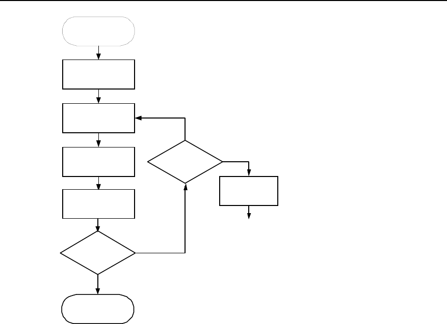
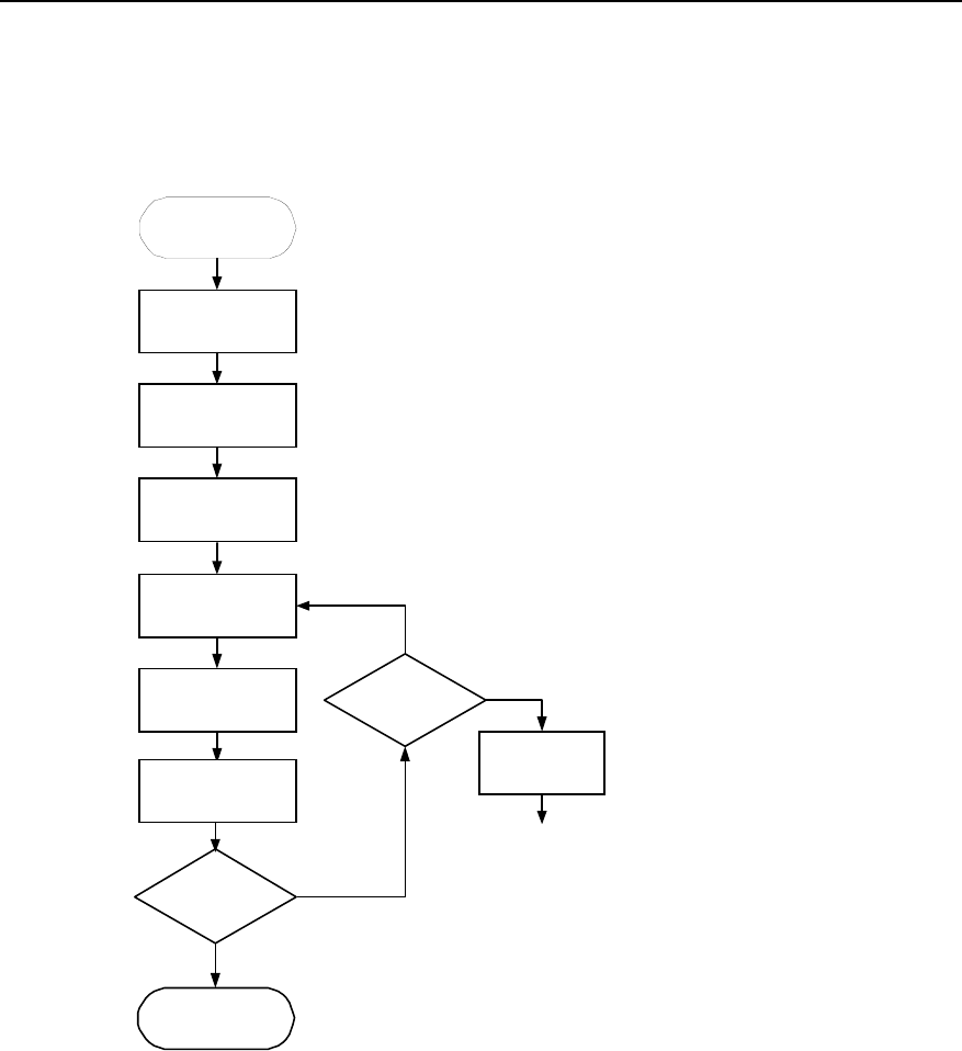
Figure 2-1 shows how to select the support according to environments.
Start
Is there anti-static
floor
Install
support
Is the ground
load is less
than 5.5kN/m2
Install lower
support
Install U-bar
support
Y
NY
N
End
Figure 2-1 Selecting assemblies for installation
2.1 Introduction to Cabinet Assemblies
This section introduces the following information of the lower support, A600 support,
and U-bar support:
z Outline
z Assemblies
Installation Manual – BTS3606 Cabinet Installation
Airbridge BTS3606&3606A CDMA Base Station Chapter 2 Installing Cabinet Assemblies
Huawei Technologies Proprietary
2-2
z Installation method
z Quantity
2.1.1 Lower Support
I. Outline
Figure 2-2 shows the outline of the lower support.
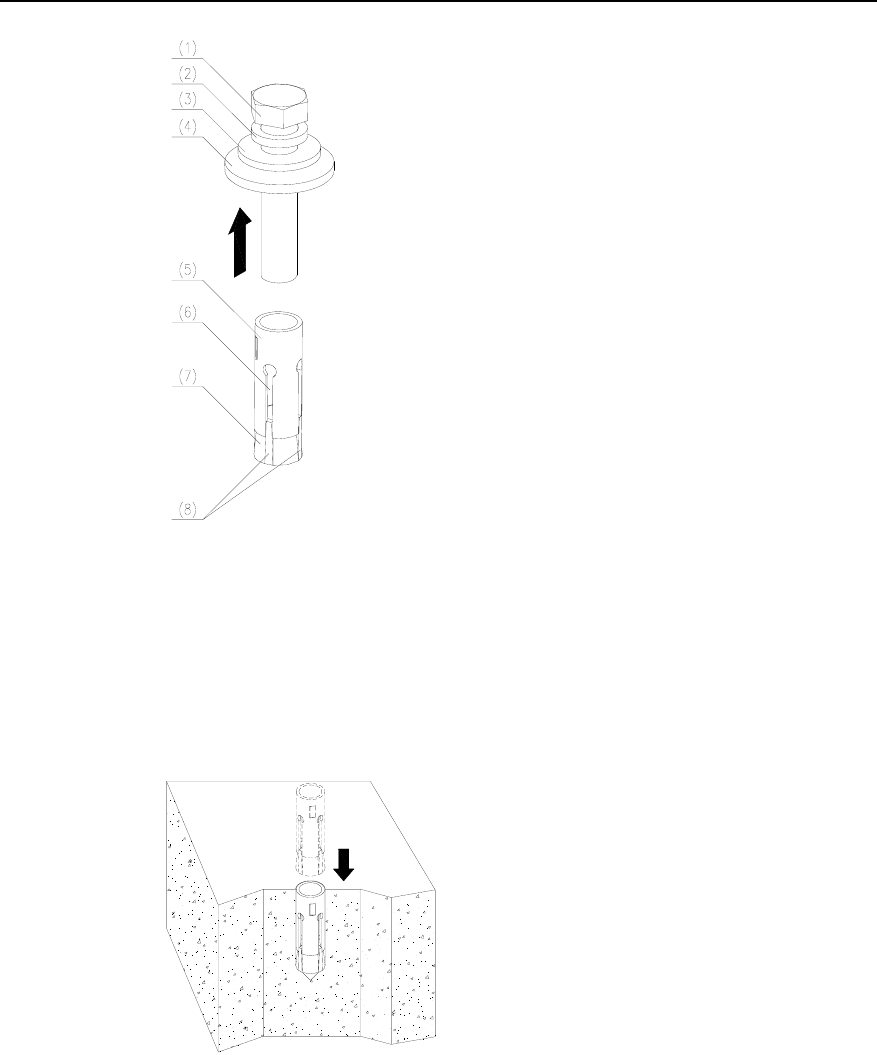
(1) Fastening bolt
Figure 2-2 Lower support
II. Assemblies
None.
III. Installation Method
The lower support is located between the cabinet and the cement floor. It is installed
in different ways depending on the installation environment. For details, see the
description of installation procedures.
IV. Quantity
One lower support is needed for each cabinet.
Installation Manual – BTS3606 Cabinet Installation
Airbridge BTS3606&3606A CDMA Base Station Chapter 2 Installing Cabinet Assemblies
Huawei Technologies Proprietary
2-3
2.1.2 A600 Support
I. Outline
Figure 2-3 shows the outline of A600 series support.
(1) Connecting hole (2) Upper support
(3) Lower support (4) Installation hole
Figure 2-3 A600 series support
II. Assemblies
A600 series includes four types of assemblies: three height-adjustable types and one
height-fixed type. Table 2-1 lists the ranges of the adjustable height.
Table 2-1 Height of A600 series supports assemblies
Assemblies Range of height
I 195 mm – 230 mm (7.7 in. – 9 in.)
II 231 mm – 300 mm (9 in. – 12 in.)
III 301 mm – 445 mm (12 in. – 17.5 in.)
IV Customized according to the floor height.
Minimum height: 140 mm (5.5 in.)

Installation Manual – BTS3606 Cabinet Installation
Airbridge BTS3606&3606A CDMA Base Station Chapter 2 Installing Cabinet Assemblies
Huawei Technologies Proprietary
2-4
Note:
The antistatic floor height refers to the distance between the upper surface of the
antistatic floor and the cement floor.
The heights of A600 series support assemblies I, II, and III can be adjusted steplessly
within their adjustable ranges. You can adjust the heights by moving the upper and
lower supports.
Type IV assembly is a height-fixed support. It is suitable for ultra-high or ultra-low
antistatic floors. But the floor cannot be lower than 140 mm (5.5 in.).
III. Installation Method
Install the support in the floor-bracketing mode. That is, bracket the floor between the
cabinet and the support, and then run the bolts through the antistatic floor to fix the
cabinet and the support. In this way, the cabinet can be firmly fixed and supported.
IV. Quantity
Two supports are needed for each cabinet.
2.2 U-bar Support
I. Outline
The U-bar support is a big base made on the site. The recommended material for the
support is the 14b-3000 type of GB707-88 hot-rolled U-bar.
Figure 2-4 shows the outline of the U-bar support.
Installation Manual – BTS3606 Cabinet Installation
Airbridge BTS3606&3606A CDMA Base Station Chapter 2 Installing Cabinet Assemblies
Huawei Technologies Proprietary
2-5
Figure 2-4 U-bar support
II. Assemblies
None.
III. Installation Method
You need to prepare the U-bar support on the site. For the specific method, see
section 2.6 “Installing Assemblies on Cement Floor with Poor Bearing Capacity”.
IV. Length
Determine the length of the U-bar support as needed.
2.3 Cabinet Layout Principle
The principle of cabinet layout is as follows:
z The space between the cabinet back and the wall must be greater than 0.6m (24
in.).
z The cabinet side can be installed against the wall.
z The path with the width no less than 0.8m (32 in.) must be reserved in front of
the cabinet.
z The cabinet must be positioned as close as possible to the feeder window to
reduce the length of the feeder cable.
It is recommended to lay three BTS cabinets in a row, as shown in Figure 2-5, one as
the main cabinet, the rest as auxiliaries.
Installation Manual – BTS3606 Cabinet Installation
Airbridge BTS3606&3606A CDMA Base Station Chapter 2 Installing Cabinet Assemblies
Huawei Technologies Proprietary
2-6
Power
distribution room
Transmission
equipment
Fe eder wind ow
BTS BTS BTS
Main Auxiliary Auxiliary
Other equipment
Environment
alarm collecting box
Figure 2-5 Layout of the equipment room
2.4 Installing Assemblies on Cement Floor
This section details the procedures of installing lower supports on the cement floor.
2.4.1 Installation Flowchart
Figure 2-6 shows how to install the cabinet assemblies (lower support) on the cement
floor.
Installation Manual – BTS3606 Cabinet Installation
Airbridge BTS3606&3606A CDMA Base Station Chapter 2 Installing Cabinet Assemblies
Huawei Technologies Proprietary
2-7
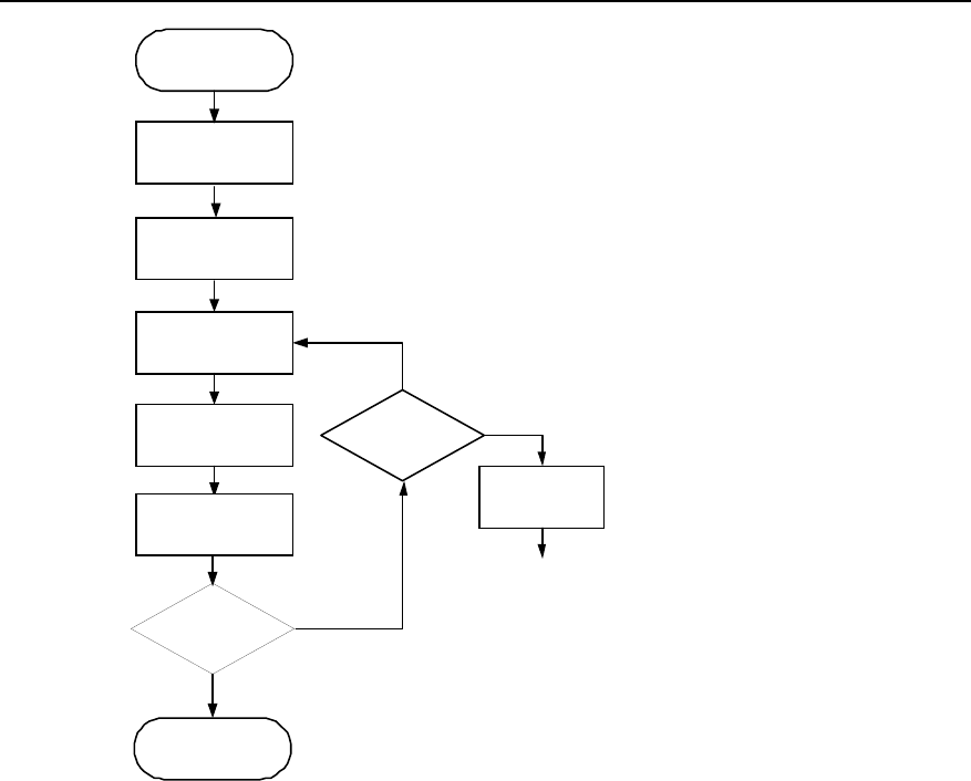
Start
Position the
cabinet
Install expansion
bolts
Fix the lower
support
Conduct
insulation test
End
OK
Failed
Check the
insulating parts
OK
Damaged
or missing
Repair/replace
the parts
Repeat
insulation test
Level the
lower support
Figure 2-6 Installation flowchart of the lower support on cement floor
2.4.2 Installation Procedure
To install lower supports on the cement floor, proceed as follows:
I. Positioning the Cabinet
To position the cabinet, proceed as follows:
1) Determine the installation position of the cabinet according to the positioning
dimensions specified in the project design and construction blueprint.
2) Place the lower support on the floor according to the cabinet layout.
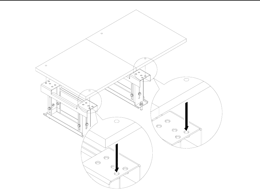
3) Mark the positions of four connecting holes of the cabinet (Each cabinet has four
connecting holes).
Installation Manual – BTS3606 Cabinet Installation
Airbridge BTS3606&3606A CDMA Base Station Chapter 2 Installing Cabinet Assemblies
Huawei Technologies Proprietary
2-8
II. Drilling Holes and Installing Expansion Bolts
Caution:
z The depth of the hole must range from 52 mm (2 in.) to 60 mm (2.4 in.) (the length
of the expansion tube plus that of the drill bit). Otherwise, the expansion bolt
cannot be fastened.
z All holes must have the same depth. Before measuring the hole depth, remove the
dust inside the hole to measure the net depth.
z If the floor is too hard and smooth to settle the drill bit, punch a pit with a chisel to
help positioning the hole.
z Make sure that the expansion tube is completely buried in the ground lest.
z Feed the guiding rib on the nut into the guiding slot of the tube first. Otherwise, the
expansion bolt can not be properly installed and secured.
To drill a hole and install the expansion bolt, proceed as follows:
1) Use the M12 expansion bolt and φ16 bit.
2) Hold the drill stock firmly with two hands, and keep the drill bit vertical to the
ground to drill a hole.
3) Clean the dust with a vacuum cleaner when drilling.
4) Take off the M12×70 bolt, spring washer, plain washer, and insulating washer,
as shown in Figure 2-7.
Installation Manual – BTS3606 Cabinet Installation
Airbridge BTS3606&3606A CDMA Base Station Chapter 2 Installing Cabinet Assemblies
Huawei Technologies Proprietary
2-9
(1) M12 x 70 bolt (2) Spring washer (3) Plain washer
(4) Insulating washer (5) Expansion tube (6) Guiding slot
(7) Nut (8) Guiding rib
Figure 2-7 Disassembling an expansion bolt
5) Feed the tube and the nut into the hole vertically and make sure that the guiding
rib on the nut meets the guiding slot of the tube, as shown in Figure 2-8.
6) Hammer the tube until it is completely buried in the ground.
Figure 2-8 Installing an expansion bolt
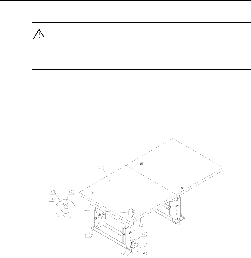
III. Fixing the Lower Support
To fix the lower support, proceed as follows:
1) Place the insulating plate and the lower support in turn aligning with the four
expansion bolts.
Installation Manual – BTS3606 Cabinet Installation
Airbridge BTS3606&3606A CDMA Base Station Chapter 2 Installing Cabinet Assemblies
Huawei Technologies Proprietary
2-10
2) Place in turn the spring washer, plain washer, and insulating covering onto the
four M12%60 bolts.
3) Lead the bolts through the lower support.
4) Diagonally fasten them to a 45 N-m (400 in-lb), as shown in Figure 2-9.
(1) M12%60 expansion bolt (2) Spring washer (3) Plain washer
(4) Insulating covering (5) Insulating plate
Figure 2-9 Installing the lower support
IV. Leveling the Lower Support
To level the lower support, proceed as follows:
1) Place a level bar in vertical direction on the top-plane of the lower support.
2) Check the levelness of the lower support.
3) When an error occurs, adjust the levelness by adding gaskets beneath the lower
support, as shown in Figure 2-10.
Installation Manual – BTS3606 Cabinet Installation
Airbridge BTS3606&3606A CDMA Base Station Chapter 2 Installing Cabinet Assemblies
Huawei Technologies Proprietary
2-11
Figure 2-10 Leveling the lower support
V. Conducting Insulation Test
To conduct an insulation test, proceed as follows:
1) Set the multimeter to "MΩ".
2) Connect the two probes to the paint-free place of the base and the expansion
bolt.
3) If the resistance is larger than 5 MΩ, the insulation is properly done. The
installation ends here. Otherwise, go to step 4.
4) Check whether any insulating covering or insulating washer is missing or
damaged. If any, replace with new parts and then conduct the insulation test
again. Otherwise, reinstall the expansion bolts and conduct the insulation test.
2.5 Installing Assemblies on Antistatic Floor
This section details the procedures of installing lower supports and A600 supports on
the antistatic floor.
Installation Manual – BTS3606 Cabinet Installation
Airbridge BTS3606&3606A CDMA Base Station Chapter 2 Installing Cabinet Assemblies
Huawei Technologies Proprietary
2-12
2.5.1 Installation Flowchart
Figure 2-11 shows how to install cabinet assemblies (support and lower support) on
the antistatic floor.
Start
Position the cabinet
Remove the
floor framework
Locate the support
at the side of
anti-static floor
Fix the support
Install the
lower support
Conduct
insulation test
End
OK
Failed
Check the
insulating parts
OK
Damaged
or missing
Repair/replace
the parts
Repeat
insulation test
Level the
lower support
Figure 2-11 Installation flowchart of support and lower support on antistatic floor
2.5.2 Installation Procedure
The following describes the procedure of installing assemblies on the antistatic floor.

Installation Manual – BTS3606 Cabinet Installation
Airbridge BTS3606&3606A CDMA Base Station Chapter 2 Installing Cabinet Assemblies
Huawei Technologies Proprietary
2-13
I. Positioning the Cabinet and Removing the Floor
Caution:
z When positioning the cabinet, try to avoid the interference between the installation
supports and the antistatic floor framework. Keep the framework intact.
z If the interference is unavoidable, remove the floor framework at the place where
the interference occurs during the installation. Align the first cabinet with the floor
edge.
To position the cabinet and remove the floor framework, proceed as follows:
1) Determine the installation position of the cabinet according to the positioning
dimensions specified in the project design and construction blueprint.
2) Place the lower support on the floor according to the cabinet layout.
3) Mark the positions of four connecting holes of the cabinet (Each cabinet has four
connecting holes).
4) Remove the lower support.
5) Use the φ20 bit to drill holes through the marked places. See section 2.4.2 II.
“Drilling Holes and Installing Expansion Bolts” for details.
6) Remove the antistatic floor for installation using a special tool (for example,
panel lifter).
7) Remove strutting pieces for the antistatic floor.
II. Locating the Support at the Side of Antistatic Floor
Note:
Install the support according to Figure 2-12. Align the connecting holes at the outer
side of the support with the floor holes to prevent the support extruding out of the
cabinet.
Installation Manual – BTS3606 Cabinet Installation
Airbridge BTS3606&3606A CDMA Base Station Chapter 2 Installing Cabinet Assemblies
Huawei Technologies Proprietary
2-14
Figure 2-12 Connection between support connecting holes and floor holes
III. To locate the support at the side of antistatic floor, proceed as follows:
1) Place the support below the antistatic floor.
2) Align the connecting holes of the support with the holes on the antistatic floor.
3) Take the installation hole of the support as the template. Mark positions for the
expansion bolts on the concrete floor.
4) Use a Φ16 drill bit to drill holes at the marked places. Details about the drilling
are available in section 2.4.2 I. "Positioning the Cabinet".
5) Install expansion bolts by following the instructions in section 2.4.2 II. "Drilling
Holes and Installing Expansion Bolts".
6) Finely adjust the height-locking bolts on the upper support until they do not slip
down by themselves.
7) Put the support back to its installation position. Run the expansion bolt through
the installation hole of the support.
Installation Manual – BTS3606 Cabinet Installation
Airbridge BTS3606&3606A CDMA Base Station Chapter 2 Installing Cabinet Assemblies
Huawei Technologies Proprietary
2-15
IV. Fixing Support
Caution:
Fasten the three bolt sets in the following order: Anchor bolt for the floor d expansion
bolt d height-lock bolt (first in the middle, then on both sides)
To fix the support, proceed as follows:
1) Align the holes on the antistatic floor with the connecting holes of the support.
2) Tighten M12×70 bolts from top to bottom.
3) Install the plain washer, spring washer, and insulating covering, as shown in
Figure 2-13.
(1) Antistatic floor (2) M12×70 bolt (3) φ12 spring washer
(4) φ12 plain washer (5) Height-lock bolts (both sides)
(6) Height-lock bolt (middle) (7) M12 nut
(8) M12×80 exploded expansion bolt
Figure 2-13 The position of anchor bolts
4) Gently knock the support with a rubber hammer to adjust the height so that the
antistatic floor falls on its original place on the framework. Make sure that the
upper plane presses against the antistatic floor.
5) Tighten the anchor bolts on the antistatic floor.
6) Make the expansion bolts cross fastened to 45 N-m (400 in-lb) with a torque
wrench one by one to reduce the stress between the bolts and the support.
7) Tighten the height-lock bolts to 45 N-m (400 in-lb) with a torque wrench. First
tighten the bolts in the middle, and then those on both sides.

Installation Manual – BTS3606 Cabinet Installation
Airbridge BTS3606&3606A CDMA Base Station Chapter 2 Installing Cabinet Assemblies
Huawei Technologies Proprietary
2-16
Figure 2-13 shows the position of anchor bolts.
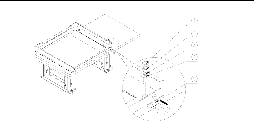
V. Installing the Lower Support
To install the lower support, proceed as follows:
1) Remove four bolts and one gasket that connect the antistatic floor and the
support.
2) Place the insulating plate and the lower support in turn.
3) Level the sections of the subrack in both the longitude and latitude directions
with a level bar, and make sure the level vial is in the middle.
z If the error is small, adjust the levelness by striking the joint between the
lower support and the support with a rubber hammer while measuring.
z If the error is big, add gaskets between the lower support and the insulating
plate to adjust the levelness.
4) Place in turn the spring washer, plain washer, and insulating covering onto the
four bolts.
5) Lead the bolts through the lower support.
6) Diagonally fasten them to 45 N-m (400 in-lb) with a torque wrench.
Note:
Install the insulating plate, insulating covering, and the plain washer as shown in
Figure 2-14. Make sure the cabinet is insulated from the earth.
Installation Manual – BTS3606 Cabinet Installation
Airbridge BTS3606&3606A CDMA Base Station Chapter 2 Installing Cabinet Assemblies
Huawei Technologies Proprietary
2-17
(1) M12%60 expansion bolt (2) Spring washer (3) Plain washer
(4) Insulating covering (5) Gasket
Figure 2-14 Installing the lower support
VI. Leveling the lower support
See section 2.4.2 IV. “Leveling the Lower Support”.
VII. Conducting insulation test
See section 2.4.2 V. “Conducting Insulation Test”.
2.6 Installing Assemblies on Cement Floor with Poor
Bearing Capacity
This section details the procedures of installing lower support and U-bar support on
cement floor of insufficient bearing capacity.
2.6.1 Installation Flowchart
Figure 2-15 shows how to install cabinet assemblies (U-bar support and lower
support) on the cement floor with insufficient bearing capacity.
Installation Manual – BTS3606 Cabinet Installation
Airbridge BTS3606&3606A CDMA Base Station Chapter 2 Installing Cabinet Assemblies
Huawei Technologies Proprietary
2-18
Position the cabinet
Prepare U-bar
support
Fix the U-bar
support
Install the
lower support
Conduct
insulation test
End
OK
Failed
Check the
insulating parts
OK
Damaged
or missing
Repair/replace
the parts
Repeat
insulation test
Level the
lower support
Start
Figure 2-15 Installation flowchart on cement floor without sufficient bearing capacity
2.6.2 Installation Procedure
The following describes the procedure of installing assemblies on the cement floor
with poor bearing capacity.
I. Positioning the Cabinet
To position the cabinet, proceed as follows:
1) Determine the installation position of the cabinet according to the positioning
dimensions specified in the project design and construction blueprint.
2) Position the U-bar support according to the cabinet layout.
3) Measure off several points with a measuring tape.
4) Draw two straight parallel benchmark lines with a marker. The spacing between
the two straight lines is 630 mm (24.8 in.).
5) Determine the position of the first hole for the U-bar support on the two lines
according to the design requirement. Take this hole as the benchmark point to
mark the rest installation holes of the support one by one.
Installation Manual – BTS3606 Cabinet Installation
Airbridge BTS3606&3606A CDMA Base Station Chapter 2 Installing Cabinet Assemblies
Huawei Technologies Proprietary
2-19
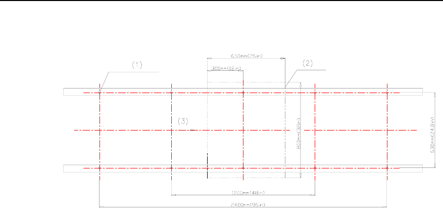
6) Re-measure the lines to confirm the accuracy of each hole. Figure 2-16
illustrates the positions of installation holes for U-bar supports.
(1) M12 expansion bolt (2) Outline of the cabinet (3) Front face of the cabinet
Figure 2-16 Installation hole positions of U-bar supports
7) Place the lower support on the floor according to the cabinet layout.
8) Mark the positions of four connecting holes of the cabinet (each cabinet has four
connecting holes) on the floor under the lower support.
9) Remove the lower support.
10) Use the φ20 bit to drill holes through the marked places.
II. Preparing U-bar Support
To prepare the U-bar support, proceed as follows:
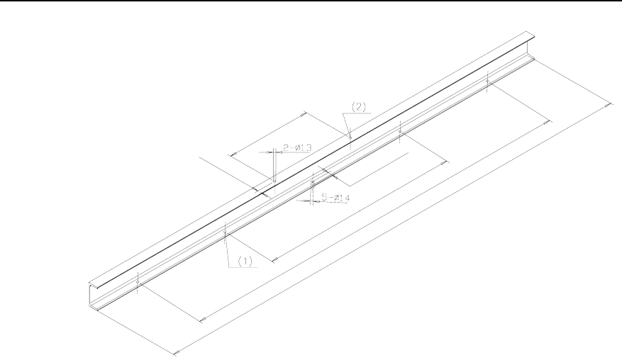
1) Drill installation holes for the cabinet and fixing holes on the U-bar, as shown in
Figure 2-16 and Figure 2-17.
Installation Manual – BTS3606 Cabinet Installation
Airbridge BTS3606&3606A CDMA Base Station Chapter 2 Installing Cabinet Assemblies
Huawei Technologies Proprietary
2-20
1200mm (47in)
2400mm (94in)
3000mm (118in)
520mm (20.5in)
25mm (1in)
25mm (1in)
(1) U-bar fixing hole (2) Installation hole of the base
Figure 2-17 Drilling holes on U-bar support
2) Remove all burrs and sharp edges.
3) Paint the whole support with rustproof coat and top-coat. The color of the coat
must be the same as or similar to that of the cabinet.
III. Fixing the U-bar Support
To fix the U-bar support, proceed as follows:
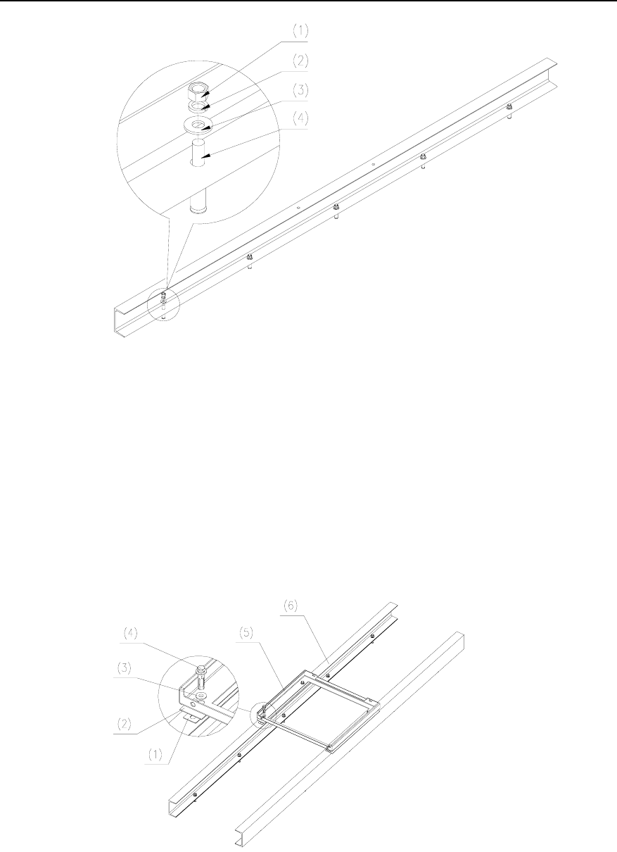
1) Install expansion bolts by following the instructions in section 2.4.2 II. "Drilling
Holes and Installing Expansion Bolts".
2) Place the U-bar support onto the installation position aligning the installation
holes with U-bar fixing holes.
3) Fasten the nuts one by one, as shown in Figure 2-18.
Installation Manual – BTS3606 Cabinet Installation
Airbridge BTS3606&3606A CDMA Base Station Chapter 2 Installing Cabinet Assemblies
Huawei Technologies Proprietary
2-21
(1) M12x80 bolt (2) Φ12 spring washer
(3) Φ12 plain washer (4) M12x80 expansion bolt
Figure 2-18 Installing the U-bar support
4) Cross-fasten the nuts of the lower support one by one to reduce the stress
between the bolts and the lower support.
5) Place the insulating plate and the lower support on the U-bar support. Align the
four holes in the insulating plate and lower support with those in the upper plane
of the U-bar support.
6) Put the spring washer, plain washer, and insulating covering on the M12%45 bolt
one by one. See Figure 2-19.
(1) Gasket (2) Insulating plate (3) Insulating covering
(4) φ12 plain washer (5) φ12 spring washer (6) M12x45 bolt
(7) Lower support (8) U-bar support
Figure 2-19 Installing the lower support

Installation Manual – BTS3606 Cabinet Installation
Airbridge BTS3606&3606A CDMA Base Station Chapter 2 Installing Cabinet Assemblies
Huawei Technologies Proprietary
2-22
7) Place the bolts with fixed fittings into the four holes and tighten them slightly.
8) Make sure the support is level and then cross-fasten the bolts of the lower
support to 45 N-m (400 in-lb) with a torque wrench.
IV. Leveling the Lower Support
See section 2.4.2 IV. “Leveling the Lower Support”.
V. Conducting Insulation Test
See section 2.4.2 V. “Conducting Insulation Test”.
Installation Manual – BTS3606 Cabinet Installation
Airbridge BTS3606&3606A CDMA Base Station Chapter 3 Installing Cabinet and Cabinet Equipment
Huawei Technologies Proprietary
3-1
Chapter 3 Installing Cabinet and Cabinet
Equipment
This chapter introduces the procedures of installing and fixing BTS3606 cabinets and
the equipment in cabinets.
3.1 Installing Cabinet
To install a BTS3606 cabinet, proceed as follows:
1) Lift the cabinet onto the lower support and align the upper support with the lower
support.
2) Push the upper support into the lower support.
3) Tighten the bolts at the front face of the cabinet.
4) Mount the cover.
5) Tighten the bolts on the cover.
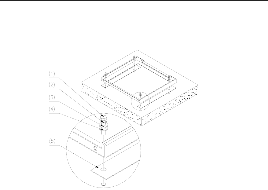
Figure 3-1 shows how to install a BTS3606 cabinet on the cement floor.
(1)
(2)
(3)
(1) Bolt for fastening the upper and lower supports
(2) Cover (3) M6x20 combined screw
Figure 3-1 Installing a cabinet on the cement floor
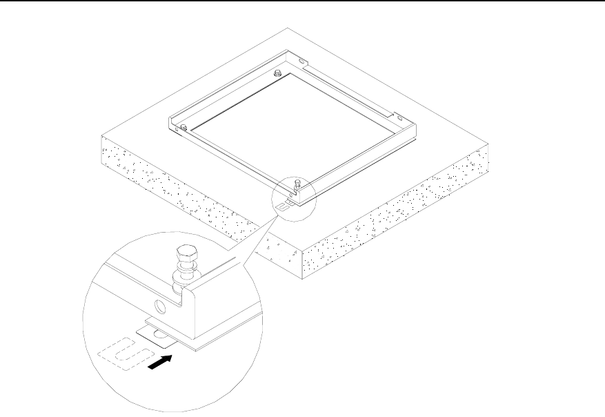
Figure 3-2 shows how to install a BTS3606 cabinet on the antistatic floor.
Installation Manual – BTS3606 Cabinet Installation
Airbridge BTS3606&3606A CDMA Base Station Chapter 3 Installing Cabinet and Cabinet Equipment
Huawei Technologies Proprietary
3-2
(1) (2) (3)
(4)(5)
(1) M12x30 bolt (2) Φ12 spring washer (3) Φ12 plain washer
(4) Cover (5) M6x20 combined screw
Figure 3-2 Installing a cabinet on the antistatic floor
Figure 3-3 shows how to install a BTS3606 cabinet on the floor without sufficient
bearing capacity.
Figure 3-3 Installing a cabinet on the floor without sufficient bearing capacity
Installation Manual – BTS3606 Cabinet Installation
Airbridge BTS3606&3606A CDMA Base Station Chapter 3 Installing Cabinet and Cabinet Equipment
Huawei Technologies Proprietary
3-3
3.2 Installing or Removing Cabinet Doors
The following provides the procedures of installing cabinet doors. To remove cabinet
doors, do it in a reverse order.
3.2.1 Installing or Removing Rear Doors
To install the rear door, proceed as follows:
1) Align the rear door with the positioning pin on the lower part at the back of the
cabinet.
2) Mount and fix six captive screws on the rear door, as shown in Figure 3-4.
Figure 3-4 The position of captive screws

Installation Manual – BTS3606 Cabinet Installation
Airbridge BTS3606&3606A CDMA Base Station Chapter 3 Installing Cabinet and Cabinet Equipment
Huawei Technologies Proprietary
3-4
3.2.2 Installing or Removing Side Doors
To install the side door, proceed as follows:
1) Align the side door with the positioning pin on one side of the cabinet.
2) Install the six captive screws on the side door.
Note:
Be careful of the protection grounding cables when installing or removing the side
doors.
3.2.3 Installing or Removing Left-Front and Right-Front Doors
The following describes the installation of the left-front door, and the installation of the
right-front door is same with it.
To install the left-front door, proceed as follows:
1) Remove the positioning pin base on the top of the cabinet. (The positioning pin on
the top of the cabinet is fixed on the positioning pin base.)
2) Align the left-front door with the positioning pin on the left bottom of the front
cabinet.
3) Match the positioning hole on the lower part of the left-front door with the
positioning pin on the front part of the cabinet base.
4) Insert the positioning pin previously removed to the positioning hole on the upper
part of the front door.
5) Fix the positioning pin base.
3.3 BTS3606 Cabinet Configuration
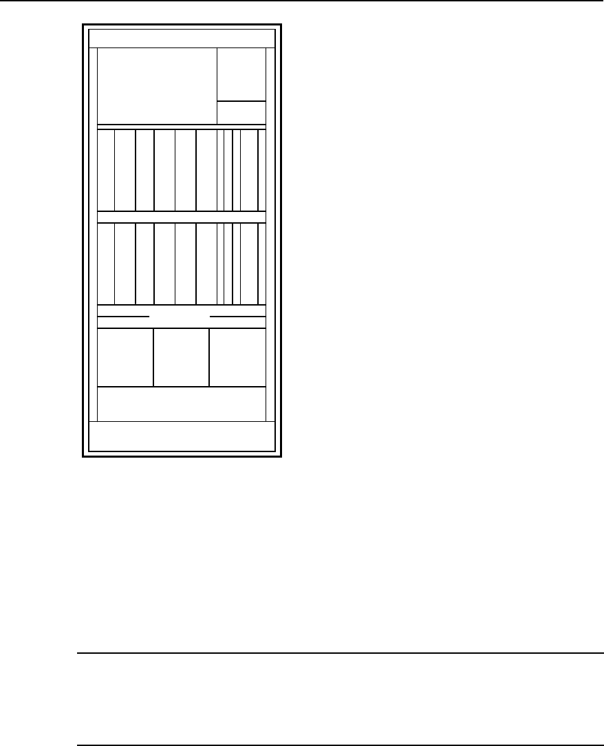
Figure 3-5 shows the BTS3606 cabinet configuration in the full configuration.
When the BTS3606 supports multi-channel configuration, the slots of the CTRMs are
configured with the CMTRs, and the slots of the CHPAs are configured with the
CMPAs.
The slots of the CCPMs in Figure 3-5 can also accommodate the CECM.
Installation Manual – BTS3606 Cabinet Installation
Airbridge BTS3606&3606A CDMA Base Station Chapter 3 Installing Cabinet and Cabinet Equipment
Huawei Technologies Proprietary
3-5
CDDU Switch box
Fan box
C
C
P
M
C
C
P
M
C
C
P
M
B
C
I
M
B
C
K
M
C
C
P
M
C
C
P
M
C
C
P
M
B
C
K
M
C
H
P
A
C
T
R
M
C
H
P
A
C
T
R
M
C
H
P
A
C
T
R
M
C
H
P
A
C
T
R
M
C
H
P
A
C
T
R
M
C
H
P
A
C
T
R
M
Cabling trough
Cabling trough
P
S
U
P
S
U
P
S
U
Tool kit
Figure 3-5 BTS3606 cabinet configuration
3.4 Installing Boards in Baseband Subrack
Baseband boards include BCIM, BCKM, and CCPM/CECM. This section explains
installation of boards in the baseband subrack and the attentions must be paid during
the operation.
Note:
The slot for the channel processing board is marked as “CEM”, that Is, channel element
module. Either the CCPM or the CECM can reside on this slot.
3.4.1 Precautions
Pay attention to the following points:
z Before installing boards and modules, check whether the DIP switches (if any) on
the backplane and the boards are correctly set according to the silk screen printed
on the boards.
Installation Manual – BTS3606 Cabinet Installation
Airbridge BTS3606&3606A CDMA Base Station Chapter 3 Installing Cabinet and Cabinet Equipment
Huawei Technologies Proprietary
3-6
z If a dummy panel is on the slot, loose the bolts and remove the dummy panel
before installing the board.
z Insert the boards according to the names on the relevant nameplates to avoid any
mistake.
z Do not touch the printed circuit board (PCB) and other components on the board,
except jumpers and DIP switches.
z Insert the board vertically and gently lest the pins and components on the
backplane be damaged.
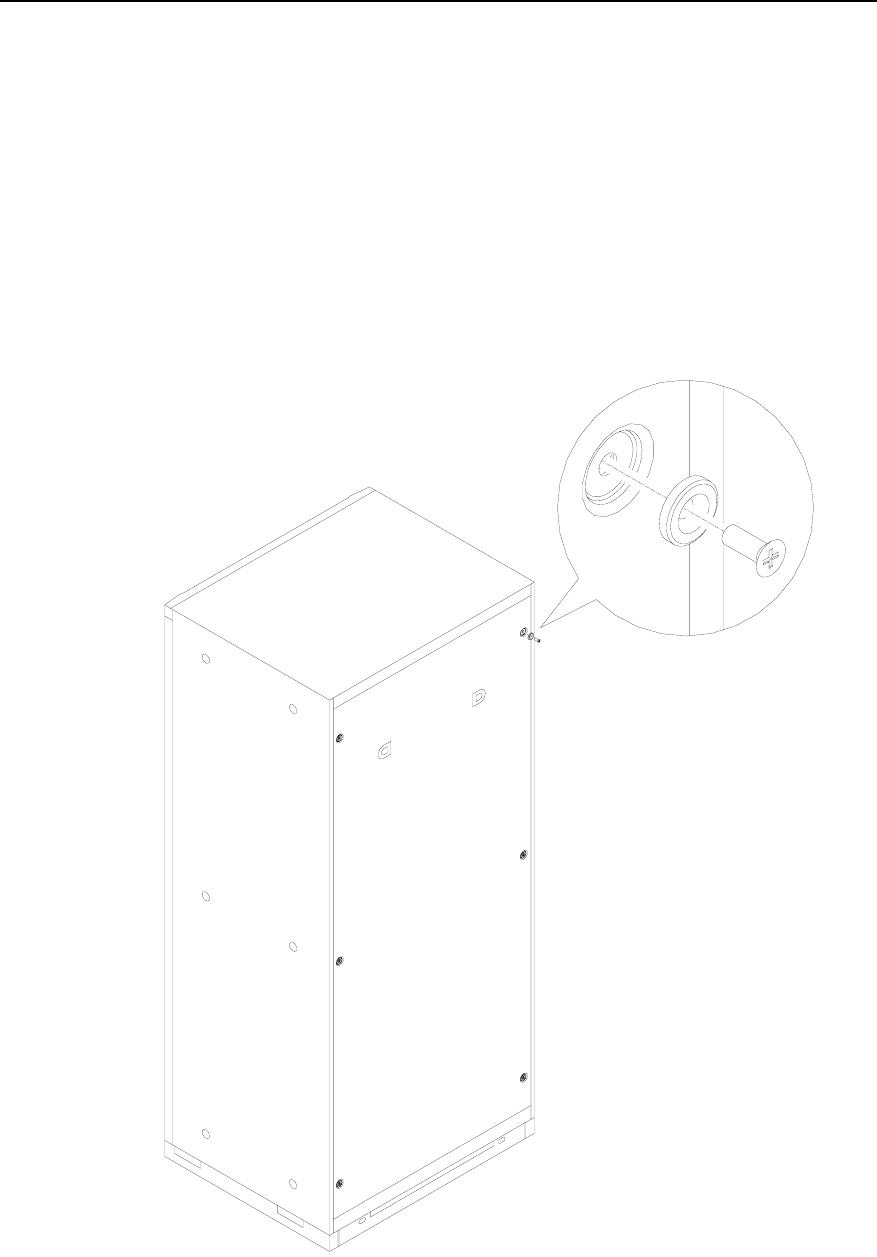
z Insert the grounding plug of the antistatic wrist strap into the antistatic jack on the
side door post of the cabinet.
3.4.2 Installation Procedure
To install the boards in the baseband subrack, proceed as follows:
1) Make sure the subracks are clean.
2) Wear an antistatic wrist strap and ground it by inserting its grounding plug to the
antistatic jack on the side door post of the cabinet.
3) Check whether there are any bent, missing or broken pins on the backplane.
z If any pin is tilted, straighten it using sharp-nose pliers in the case of
emergency.
z If any pin is missing or broken, replace the backplane.
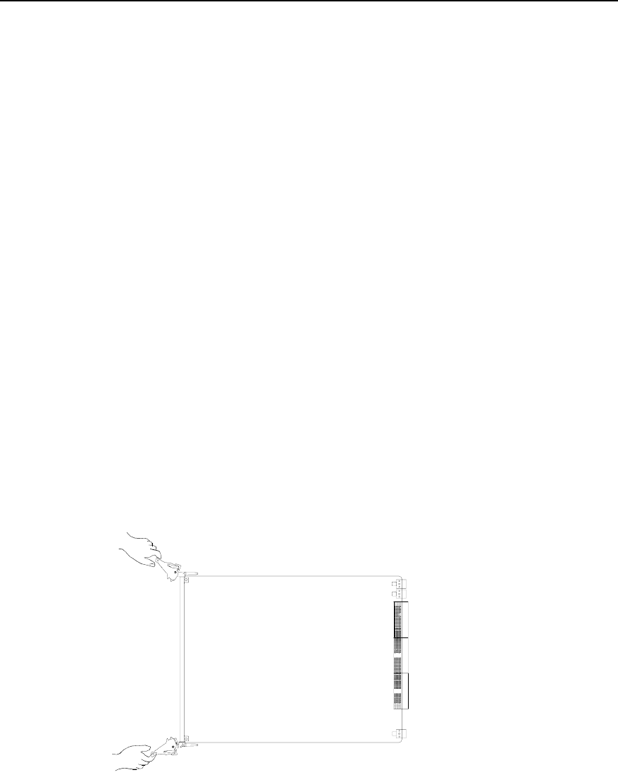
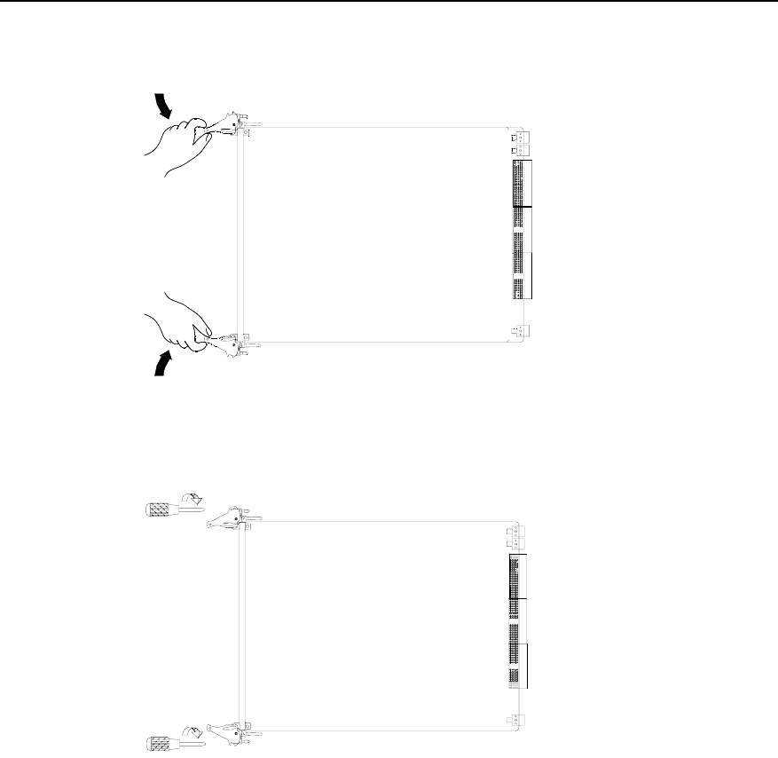
4) Make sure the ejector levers on the front panel are in the state as shown in Figure
3-6.
Figure 3-6 Installing a board (1)
5) Hold the upper ejector lever on the front panel with one hand and uplift the board
with the other.
6) Put the board on the right guide rail.
7) Hold the two ejector levers and insert the board along the guide rail gently until it
is fully engaged.
Installation Manual – BTS3606 Cabinet Installation
Airbridge BTS3606&3606A CDMA Base Station Chapter 3 Installing Cabinet and Cabinet Equipment
Huawei Technologies Proprietary
3-7
8) Turn the two ejector levers towards the middle of the panel to fix the board, as
shown in Figure 3-7.
Figure 3-7 Installing a board (2)
9) Tighten the screws clockwise on the front panel, as shown in Figure 3-8.
Figure 3-8 Installing a board (3)
3.5 Installing Modules in RF Subrack
RF modules include CTRM, CHPA, CMTR, CMPA, and CDDU. This section introduces
the installation of modules in the RF subrack and precautions.
3.5.1 Precautions
The transmit and receive performance of the BTS may degrade if the CTRM/CMTR,
CDDU, or other RF modules are fastened before being inserted in position.
3.5.2 Installation Procedure
To install a module in the RF subrack, proceed as follows:
1) Make sure the subrack is clean.

Installation Manual – BTS3606 Cabinet Installation
Airbridge BTS3606&3606A CDMA Base Station Chapter 3 Installing Cabinet and Cabinet Equipment
Huawei Technologies Proprietary
3-8
2) Wear an antistatic wrist strap and insert the grounding terminal of the wrist strap
into the anti-static jack on the side door of the cabinet.
3) Align the RF module with the relevant subrack.
4) Insert the module gently along the guide rail until it is fully engaged.
5) Fasten all screws onto the panel one by one and ensure that the module panel is
in full contact with the subrack.
Note:
z The modules are removed in the reverse order of installing them.
z CDDUs are installed from the top down, and they are not equipped with RF fans.
3.6 Installing Power Module
The BTS3606 power module is a DC/DC unit. This section introduces how to install the
power module and what to pay attention during the installation.
3.6.1 Precautions
Pay attention to the following points during the installation:
z Insert or remove the boards according to the board names on the nameplates to
avoid any mistake.
z Insert the boards with care to prevent damage to the pins on the backplane.
z Never tighten the captive screw with too much force. If necessary, reinstall the
module and align the mounting holes in the module with those in the subrack.
3.6.2 Installation Procedure
To install the power module, proceed as follows:
1) Clean up the cabinet and the subrack.
2) Check whether there are any bent, missing or broken pins on the backplane (the
side connected with the module).
z If any pin is bent, straighten it.
z If any pin is missing or broken, replace the backplane.
3) Wear the antistatic wrist strap and insert the grounding terminal of the wrist strap
into the anti-static jack on the side door of the cabinet.
4) Remove the dummy panel.
5) Align the board with the corresponding guide rail according to the board name on
the nameplate.
6) Insert the board along the corresponding guide rail until it is in position.
7) Tighten the four captive screws on the panel.

Installation Manual – BTS3606 Cabinet Installation
Airbridge BTS3606&3606A CDMA Base Station Chapter 3 Installing Cabinet and Cabinet Equipment
Huawei Technologies Proprietary
3-9
3.7 Installing Other Functional Modules
The installation procedure of other functional modules such as fan box is the same as
that of RF modules. For details, see section 3.5.2 “Installation Procedure”.
Note:
Normally, the fan box is installed upon delivery. No field installation of the fan box is
required.
3.8 Installing Equipment in Extension Cabinet
When BTS3606 cabinets are combined, the slots for the BCKM and CCPM/CECM in
the extension cabinet are configured with the TMCM and LECM. To install the TMCM
and LECM, proceed as follows:
z Insert the TMCM into the slot of the BCKM in the upper half part of the combined
subrack.
z Insert LECMs into the slots of the CCPM/CECM in the upper half part of the
combined subrack from right to left. A maximum of three LECMs can be
configured.
For instructions on the installation of modules and boards, see sections 3.1 to 3.7 .
Installation Manual – BTS3606 Cabinet Installation
Airbridge BTS3606&3606A CDMA Base Station Chapter 4 Installing Cables
Huawei Technologies Proprietary
4-1
Chapter 4 Installing Cables
This chapter introduces the types of cables to be installed, the procedures of
installing cables, and related precautions.
Note:
Cables on the backplane of the cabinet are installed and checked before delivery.
Thus, you do not need to install these cables on site. For details, see Airbridge
BTS3606&3606A CDMA Base Station Hardware Description Manual. Installation of
feeders is introduced separately in Airbridge BTS3606&3606A CDMA Base Station
Installation Manual – Antenna & Feeder Installation.
4.1 Types and Functions of Cables to Be Installed on Site
Table 4-1 describes cables to be installed on site.
Table 4-1 Cables to be installed on site
Type Description Color Specifications
RF cables between
CDDU/CHPA/CTRM. Black
1/4 in. The two ends of a
jumper are DIN
connectors. The external
connector is a DIN-female
connector.
RF cables between
CDDU/CMPA/CMTR. Black
1/4 in. The two ends of a
RF cable are DIN
connectors. The external
connector is a DIN-female
connector.
RF cables
Jumpers between the
cable inlet of the
cabinet and feeders Black 1/2 in. The two ends of a
jumper are DIN
connectors.

Installation Manual – BTS3606 Cabinet Installation
Airbridge BTS3606&3606A CDMA Base Station Chapter 4 Installing Cables
Huawei Technologies Proprietary
4-2
Type Description Color Specifications
Two-phase power
cables (110 V),
including two live
cables (L) and one
neutral cable (N)
L: red
N: black
L: The sectional area is 35
mm2.
N: The sectional area is
35 mm2.
Three-phase power
cables (220 V),
including three live
cables (L) and one
neutral cable (N)
L: red
N: black
L: The sectional area is 16
mm2.
N: The sectional area is
25 mm2.
Power
cables
Single-phase power
cables (220 V),
including one live cable
(L) and one neutral
cable (N)
L: red
N: black
L: The sectional area is 25
mm2.
N: The sectional area is
25 mm2.
Grounding
cables PGND cables Yellow-green The sectional area is 25
mm2.
Optical
fibers for
connecting
the ODU
Single-mode optical
fibers for connecting
ODU3601Cs Orange 2 x Φ2 mm
75Ω E1 White 75Ω coaxial cables
120Ω E1 White 120Ω twisted pairs
E1/T1
cables
100Ω T1 White 100Ω twisted pairs
Cables
connected
with EAC 8-core shielded cables White
The outer diameter is 5.6
mm. One end is a
DB25PIN-male connector,
and the other is a
9PIN-male connector.
RS485 serial port
cables White The outer diameter is 7
mm.
Optical fibers Orange 2 x Φ2 mm
Cables of
combined
cabinets
RF cables of GPS Black
1/4 in. The two ends of a
jumper are DIN
connectors. The external
connector is a DIN-female
connector.
Table 4-2 describes functions of the cables to be installed on site.

Installation Manual – BTS3606 Cabinet Installation
Airbridge BTS3606&3606A CDMA Base Station Chapter 4 Installing Cables
Huawei Technologies Proprietary
4-3
Table 4-2 Functions of cables
Type Description
RF cables RF cables include the GPS/GLONASS clock RF cables, RF
cables connected to the CDDU, and jumpers for multi-channel
configuration.
Grounding
cables
Grounding cables include PGND cables of the cabinet and GND
cables for cabling racks. Grounding cables for cabling racks
include GND cables for indoor cabling racks and for outdoor
cabling racks.
Power cables The –48 V DC power is led to the terminal block on top of
BTS3606 through the power cable to supply power for the whole
BTS.
Optical fibers
Optical fibers connect the CCPM/CECM of the BTS baseband
subrack and the MTRM of the soft site.
Optical fibers of combined cabinets transmit signals between the
basic cabinet and extension cabinet.
Transmission
cables
A transmission cable is made up of E1/T1 trunks (Generally, a
transmission cable contains four E1/T1 trunks). It provides trunk
connection from BTS to the BSC or other BTSs.
Cables
connected with
EAC
Cables connecting the EAC and the BTS3606 cabinet include a
data cable and a shared grounding cable.
The EAC report environment alarm information collected to the
BTS through the data cable. The EAC shares the same ground
with the BTS through the shared grounding cable.
Cables of
combined
cabinets
RF cables and optical fibers connect the basic cabinet and
extension cabinet when BTS3606 cabinets are combined to
realize communication between them.
4.2 Installing RF Cables
The RF cables to be installed on site include:
z GPS/GLONASS clock RF cables
z RF cables between CDDU/CHPA/CTRM (single-channel)
z RF cables between CDDU/CMPA/CMTR (multi-channel)
Installation Manual – BTS3606 Cabinet Installation
Airbridge BTS3606&3606A CDMA Base Station Chapter 4 Installing Cables
Huawei Technologies Proprietary
4-4
4.2.1 Installing GPS/GLONASS Clock RF Cables
Note:
The BTS3606 is configured with two black flexible RF cables. One end of the RF
cable is connected to the GPS/GLONASS feeder interface on top of the cabinet, and
the other end is placed in the cable trough of the baseband subrack upon delivery
and is to be connected to the front panel of BCKM in the baseband subrack during
cable installation.
To install GPS/GLONASS clock RF cables, proceed as follows:
1) Check that the feeder is connected to the GPS connector on the top of the
cabinet.
2) Select a cable marked with GPS_0.
3) Connect the cable to the ANT connector of the BCKM front panel.
If the BTS3606 is configured with two BCKM boards, each board must be configured
with a set of GPS/GLONASS synchronization antenna feeder. In this case, connect
cables to the ANT connectors on the BCKM front panel according to cables labels.
4.2.2 Installing RF Cables Between CDDU/CHPA/CTRM (Single-Channel)
The connection of RF cables varies with the configurations of RF modules. Table 4-3
provides the typical configuration of a single cabinet.
Table 4-3 Typical configuration of a single cabinet
Typical
configuration Quantity
of CDDU Quantity
of CHPA Diversity LNA
status in CRRM Quantity of
CPCM
O(1) 1 1
Normal
amplification 0
O(2) 1 2 Bypass 0
S(1/1/1) 3 3
Normal
amplification 0
S(2/2/2/) 3 6 Bypass 0
O(1) power synthesis 1 2 Normal
amplification 1
S(1/1/1) power
synthesis 3 6
Normal
amplification 3
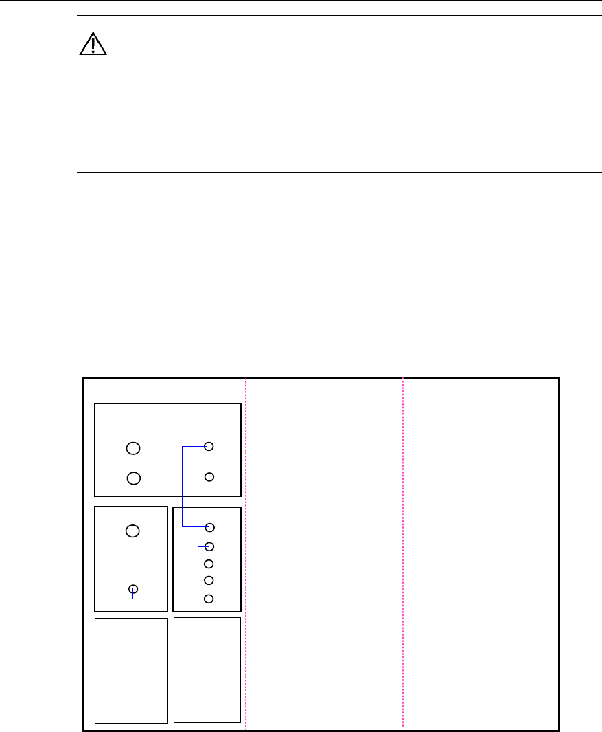
Installation Manual – BTS3606 Cabinet Installation
Airbridge BTS3606&3606A CDMA Base Station Chapter 4 Installing Cables
Huawei Technologies Proprietary
4-5
Caution:
z Watch out for the sharp edges on the RF fan panel during the installation of RF
cables lest it hurt your fingers.
z When installing the RF cable, connect unused connectors to matching load and
secure them.
The following describes the connections of the RF cables in various typical
configurations.
I. O(1) Configuration
The O(1) refers to an omni cell with one carrier. Figure 4-1 shows RF cable
connections, indicated by blue lines.
Sector A Sector B Sector C
TX1
TX2
CTRM
RX2
PAout
TX1
TX2
MRO
MRI
DRI
PAin
CHPA
RX1
CDDU
D1 D2
D4
D3
Figure 4-1 O(1) configuration
II. O(2) Configuration
The O(2) refers to an omni cell with two carriers. Figure 4-2 shows RF cable
connections, indicated by blue lines.
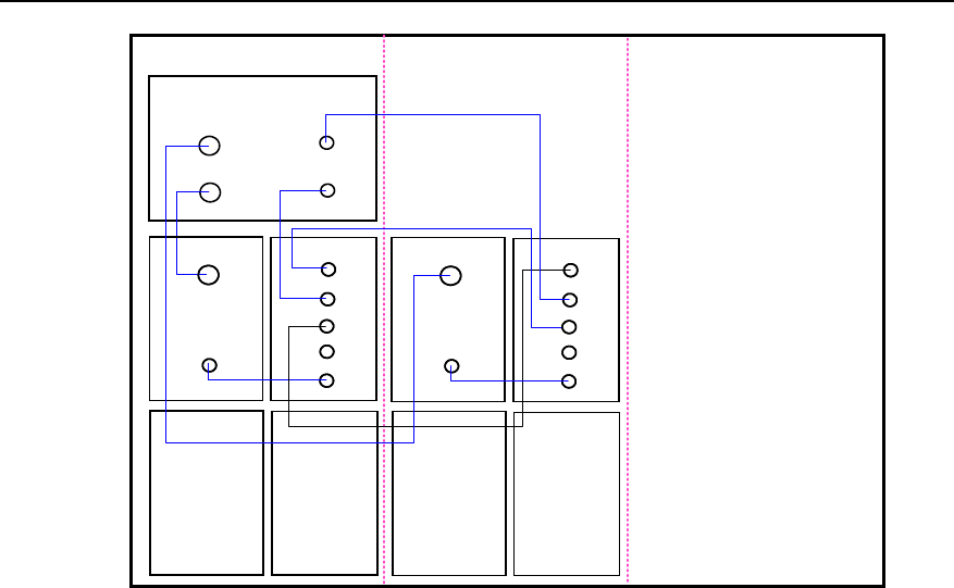
Installation Manual – BTS3606 Cabinet Installation
Airbridge BTS3606&3606A CDMA Base Station Chapter 4 Installing Cables
Huawei Technologies Proprietary
4-6
Sector A Sector B Sector C
TX1
TX2
CTRM
RX2
PAout
TX1
TX2
MRO
MRI
DRI
PAin
CHPA
RX1
CDDU
CTRM
PAout
TX1
TX2
MRO
MRI
DRI
PAin
CHPA CTRM
PAout
TX1
TX2
MRO
MRI
DRI
PAin
CHPA CTRM
PAout
TX1
TX2
MRO
MRI
DRI
PAin
CHPA
D4
D8
D7
D6
D3
D5
D1
D2
Figure 4-2 O(2) configuration
III. S(1/1/1) Configuration
The S(1/1/1) refers to the configuration of three sectors, each of which is configured
with one carrier. Figure 4-3 shows RF cable connections, indicated by blue lines.
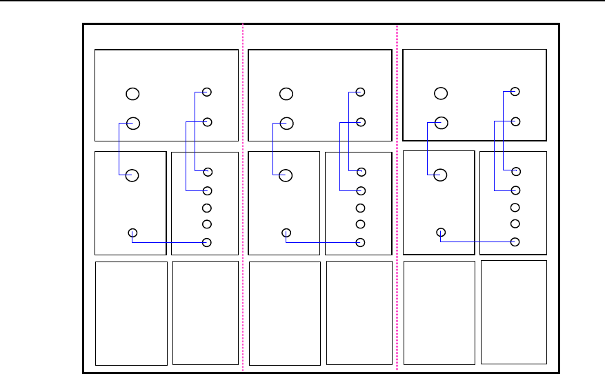
Installation Manual – BTS3606 Cabinet Installation
Airbridge BTS3606&3606A CDMA Base Station Chapter 4 Installing Cables
Huawei Technologies Proprietary
4-7
Sector A Sector B Sector C
TX1
TX2
CTRM
RX2
PAout
TX1
TX2
MRO
MRI
DRI
PAin
CHPA
RX1
CDDU
TX1
TX2
CTRM
RX2
PAout
TX1
TX2
MRO
MRI
DRI
PAin
CHPA
RX1
CDDU
TX1
TX2
CTRM
RX2
PAout
TX1
TX2
MRO
MRI
DRI
PAin
CHPA
RX1
CDDU
D1
D4
D3
D2
D7
D12
D11
D10
D9
D8
D6D5
Figure 4-3 S(1/1/1) configuration
IV. S(2/2/2) Configuration
The S(2/2/2) refers to the configuration of three sectors, each of which is configured
with two carriers. Figure 4-4 shows RF cable connections, indicated by blue lines.
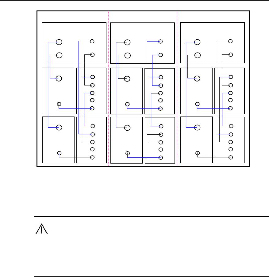
Installation Manual – BTS3606 Cabinet Installation
Airbridge BTS3606&3606A CDMA Base Station Chapter 4 Installing Cables
Huawei Technologies Proprietary
4-8
Sector A Sector B Sector C
TX1
TX2
CTRM
RX2
PAout
TX1
TX2
MRO
MRI
DRI
PAin
CHPA
RX1
CDDU
CTRM
PAout
TX1
TX2
MRO
MRI
DRI
PAin
CHPA
CTRM
PAout
TX1
TX2
MRO
MRI
DRI
PAin
CHPA
TX1
TX2
CTRM
RX2
PAout
TX1
TX2
MRO
MRI
DRI
PAin
CHPA
RX1
CDDU
CTRM
PAout
TX1
TX2
MRO
MRI
DRI
PAin
CHPA
CTRM
PAout
TX1
TX2
MRO
MRI
DRI
PAin
CHPA
TX1
TX2
CTRM
RX2
PAout
TX1
TX2
MRO
MRI
DRI
PAin
CHPA
RX1
CDDU
CTRM
PAout
TX1
TX2
MRO
MRI
DRI
PAin
CHPA
CTRM
PAout
TX1
TX2
MRO
MRI
DRI
PAin
CHPA
D8
D20
D10
D5
D6
D19
D18
D16
D17
D2
D4
D3
D14
D13
D23
D11
D22
D9
D7 D12
D24
D15
D1
D21
Figure 4-4 S(2/2/2) configuration
V. O(1) Power Synthesis
Caution:
When configuring the power synthesis function, use the RF cables supplied by the
same manufacturer. In addition, the cables connecting CTRMs and CDDUs must be
of the same length.
Figure 4-5 illustrates the connections of RF cables for the power synthesis in the case
of O(1) configuration. The connections are indicated by blue lines.
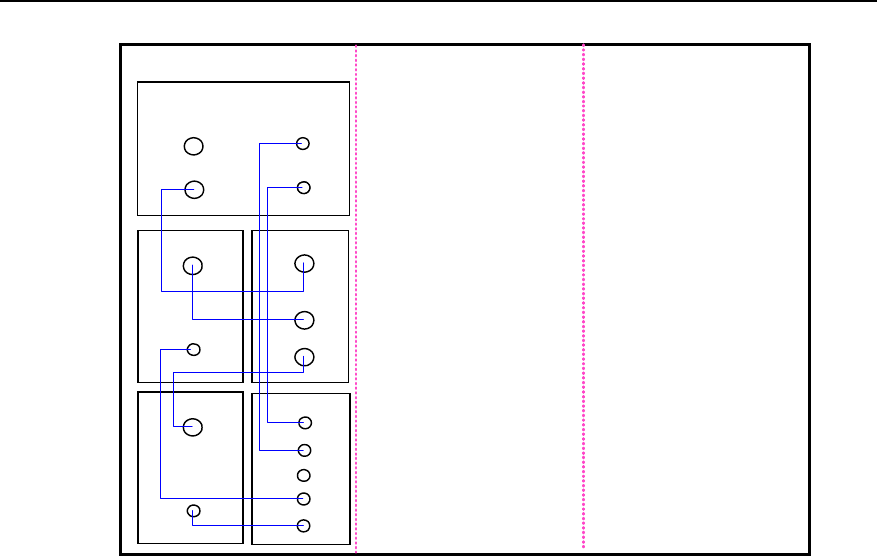
Installation Manual – BTS3606 Cabinet Installation
Airbridge BTS3606&3606A CDMA Base Station Chapter 4 Installing Cables
Huawei Technologies Proprietary
4-9
Sector A Sector B Sector C
TX1
TX2
CTRM
RX2
PAout
TX1
TX2
MRO
MRI
DRI
PAin
CHPA
RX1
CDDU
PAout
PAin
CHPA
CCPM
D1
D5
D4
D7
D6
D3
D2
Figure 4-5 O(1) power synthesis
VI. S(1/1/1) Power Synthesis
Figure 4-6 illustrates the connections of RF cables for the power synthesis in the case
of S(1/1/1) configuration. The connections are indicated by blue lines.
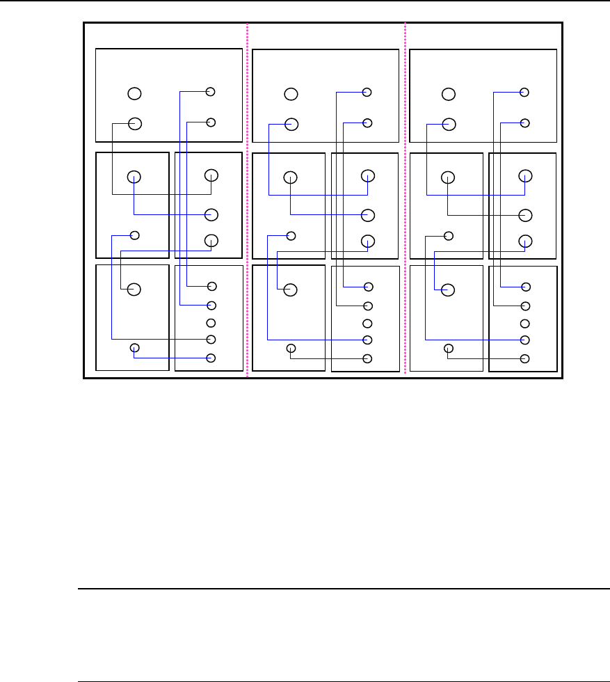
Installation Manual – BTS3606 Cabinet Installation
Airbridge BTS3606&3606A CDMA Base Station Chapter 4 Installing Cables
Huawei Technologies Proprietary
4-10
Sector A Sector B Sector C
TX1
TX2
CTRM
RX2
PAout
TX1
TX2
MRO
MRI
DRI
PAin
CHPA
RX1
CDDU
PAout
PAin
CHPA
CCPM
TX1
TX2
CTRM
RX2
PAout
TX1
TX2
MRO
MRI
DRI
PAin
CHPA
RX1
CDDU
PAout
PAin
CHPA
CCPM
TX1
TX2
CTRM
RX2
PAout
TX1
TX2
MRO
MRI
DRI
PAin
CHPA
RX1
CDDU
PAout
PAin
CHPA
CCPM
D16
D21
D15
D20
D19
D18
D3 D17
D14
D12
D13
D11
D10 D8
D9
D7
D5
D4
D6
D1
D2
Figure 4-6 S(1/1/1) power synthesis
4.2.3 Installing RF Cables Between CDDU/CMPA/CMTR (Multi-Channel)
When the BTS3606 supports the multi-channel mode, the slots of the CHPAs are
configured with the CMPAs, and the slots of the CTRMs with the CMTRs.
Note:
The BTS3606 in the multi-channel mode does not support the power synthesis
function.
The following describes the connections of the RF cables in various typical
configurations.
I. O(1) Configuration
The O(1) refers to an omni cell with one carrier. Figure 4-7 shows RF cable
connections, indicated by blue lines.
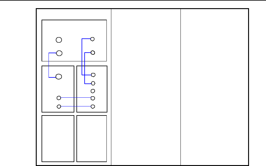
Installation Manual – BTS3606 Cabinet Installation
Airbridge BTS3606&3606A CDMA Base Station Chapter 4 Installing Cables
Huawei Technologies Proprietary
4-11
TX1
TX2 RX2
RF_out
Sample
CMPA
RX1
CDDU
Sector ASectorBSector C
CMTR
TXF
TX2
MRO
MRI
DRI
RF_in
Figure 4-7 O(1) configuration
II. O(2) Configuration
The O(2) refers to an omni cell with two carriers. Figure 4-8 shows RF cable
connections, indicated by blue lines.
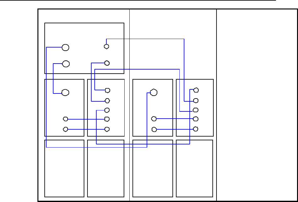
Installation Manual – BTS3606 Cabinet Installation
Airbridge BTS3606&3606A CDMA Base Station Chapter 4 Installing Cables
Huawei Technologies Proprietary
4-12
TX1
TX2 RX2
RF_out
Sample
CMPA
RX1
CDDU
Sector ASector BSector C
CMTR
TXF
TX2
MRO
MRI
DRI
CMPA CMTR
TXF
TX2
MRO
MRI
DRI
Sample
RF_in RF_in
RF_out
Figure 4-8 O(2) configuration
III. S(1/1/1), Low-Power S(2/2/2), and Low-Power S(3/3/3) Configurations
Figure 4-9 shows RF cable connections for the S(1/1/1) configuration, indicated by
blue lines. RF cable connections for the low-power S(2/2/2) configuration and
low-power S(3/3/3) are the same as that for S(1/1/1) configuration, but the settings of
software parameters are different.
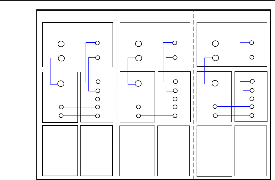
Installation Manual – BTS3606 Cabinet Installation
Airbridge BTS3606&3606A CDMA Base Station Chapter 4 Installing Cables
Huawei Technologies Proprietary
4-13
TX
1
TX
2
RX
2
Sample
CMPA
RX
1
CDDU
Sector A Sector B Sector C
CMTR
TX
F
TX
2
MRO
MR
I
DR
I
TX
1
TX
2
RX
2
CMPA
RX
1
CDDU
CMTR
TXF
TX
2
MRO
MR
I
DR
I
TX
1
TX
2
RX
2
CMPA
RX
1
CDDU
CMTR
TXF
TX
2
MRO
MR
I
DR
I
Sample Sample
RF_in RF_in RF_in
RF_out RF_out RF_out
Figure 4-9 S(1/1/1), Low-Power S(2/2/2), and Low-Power S(3/3/3) configuration
IV. High-Power S(2/2/2), High-Power S(3/3/3), S(4/4/4), S(5/5/5), and S(6/6/6)
Configurations
Figure 4-10 shows RF cable connections for the high-power S(2/2/2) configuration,
indicated by blue lines. RF cable connections for the rest configurations are the same
as that for the high-power S(2/2/2) configuration, but the settings of software
parameters are different.
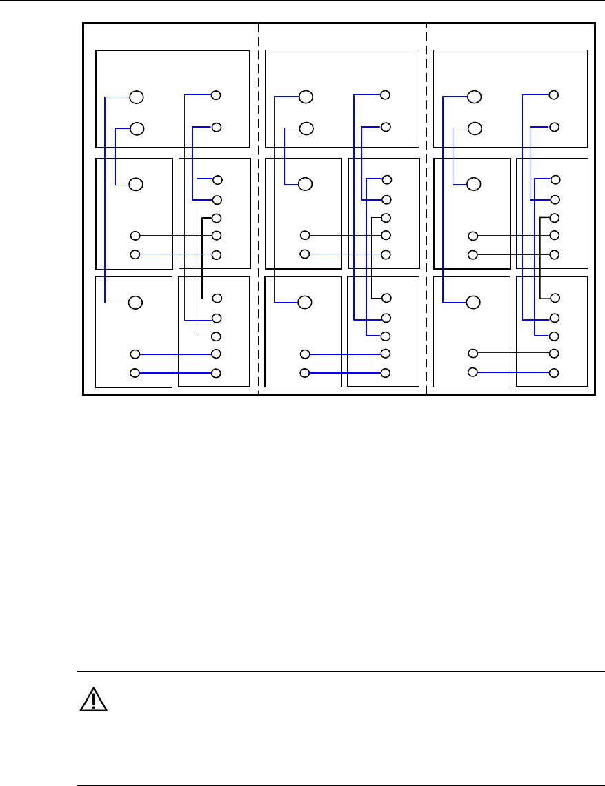
Installation Manual – BTS3606 Cabinet Installation
Airbridge BTS3606&3606A CDMA Base Station Chapter 4 Installing Cables
Huawei Technologies Proprietary
4-14
TX
1
TX
2
RX
2
CMPA
RX
1
CDDU
Sector A Sector B Sector C
CMTR
TXF
TX
2
MRO
MR
I
DR
I
CMPA CMTR
TX
F
TX
2
MRO
MR
I
DR
I
TX
1
TX
2
RX
2
CMPA
RX
1
CDDU
CMTR
TXF
TX
2
MRO
MR
I
DR
I
CMPA CMTR
TXF
TX
2
MRO
MR
I
DR
I
TX
1
TX
2
RX
2
CMPA
RX
1
CDDU
CMTR
TXF
TX
2
MRO
MR
I
DR
I
CMPA CMTR
TXF
TX
2
MRO
MR
I
DR
I
Sample
RF_in
Sample
RF_in
Sample
RF_in
Sample
RF_in
Sample
RF_in
Sample
RF_in
RF_out
RF_out RF_out
RF_out RF_out
RF_out
Figure 4-10 High-Power S(2/2/2), High-Power S(3/3/3), S(4/4/4), S(5/5/5), and
S(6/6/6) configuration
4.3 Installing Power Cables
The installation procedures of power cables include:
z Preparing power cables
z Connecting power cables
z Routing power cables
Caution:
For the 24 V power input, the voltage drop of the cable from the 24 V power supply
system to the power input port of the BTS3606 must be less than or equal to 0.5 V.
4.3.1 Preparing Power Cables
This section lists the required tools and introduces the procedure of preparing power
cables.
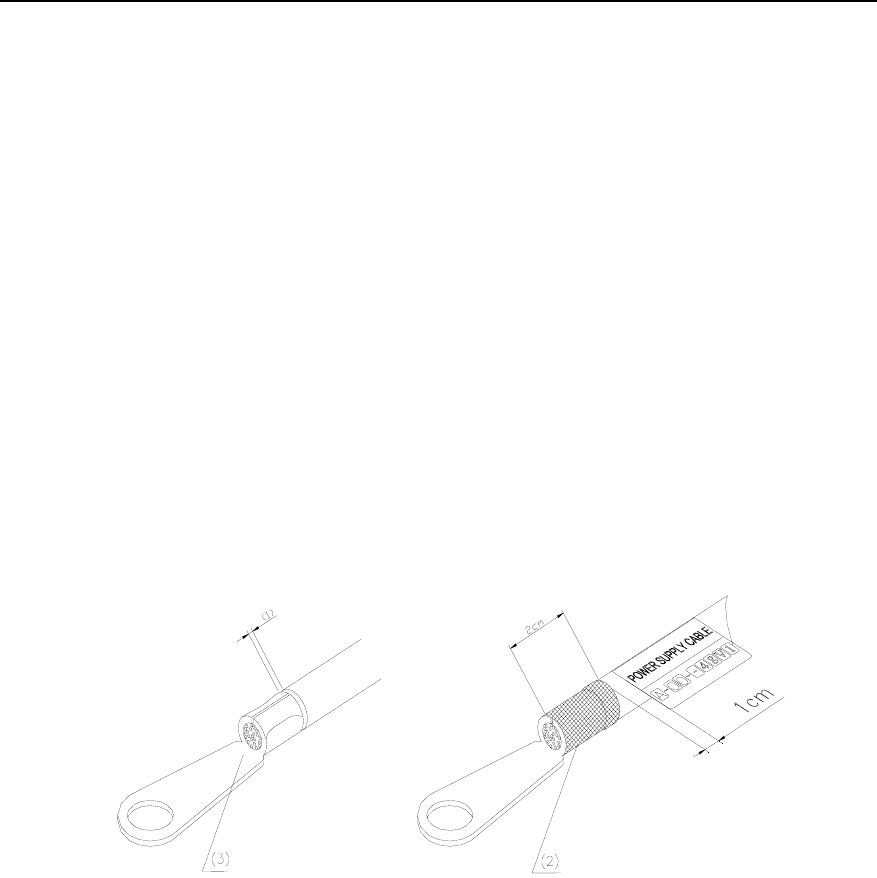
Installation Manual – BTS3606 Cabinet Installation
Airbridge BTS3606&3606A CDMA Base Station Chapter 4 Installing Cables
Huawei Technologies Proprietary
4-15
I. Tools
The following tools are required: tape, wire nipper, paper knife, hydraulic pliers,
insulating tapes, soldering iron, and solder wire.
II. Procedure
To prepare power cables, proceed as follows:
1) According to the cabling route of power cables and grounding cables, measure
the distance from the input port of the lightning arrester to the binding post of the
power distribution box.
2) Cut cables according to the distance measured. The cables must be a bit longer
than the distance measured so that it will not be too taut when routed.
3) Cut the insulating cover of each cable head with the paper knife. The length of
the removed cover must be equal to that of the cable lug.
4) Tighten the lug with hydraulic pliers.
5) Coat the lug and the naked cable with insulating tape, as shown in Figure 4-11.
Do not expose lugs and naked cables.
(1) The interval is less than 1 mm (2) Wrap up with tapes
(3) The naked stubs are covered with cable caps
Figure 4-11 Preparing lugs
4.3.2 Connecting Power Cables
This section introduces the connecting procedure of various power cables.
I. Connecting –48 V Power Cable (Blue) to the Cabinet
To connect a –48 V power cable to the cabinet, proceed as follows:
1) Remove the covers on the EMI filter and the power input terminal block by using
a screwdriver.
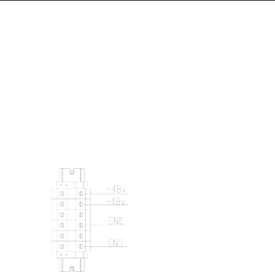
Installation Manual – BTS3606 Cabinet Installation
Airbridge BTS3606&3606A CDMA Base Station Chapter 4 Installing Cables
Huawei Technologies Proprietary
4-16
2) Put the cold-pressed terminal of the –48V power cable through the
cable-bundling strip beside the terminal block.
3) Loosen the screw in the small round hole (such as –48V connecting hole) on the
power input side of the terminal block using a flat-head screwdriver.
4) Insert the cold-pressed terminal of the –48V power cable into –48V connecting
hole of the terminal block.
5) Tighten the screw in the –48V connecting hole using a flat-head screwdriver (that
is, reverse the step 3 above) and fix the power cable to the terminal block.
6) Bind power cables to the cable-bundling strip using cable ties.
II. Connecting Power Grounding Cables (Black) to the Cabinet
To connect power grounding cables to the cabinet, proceed as follows:
1) Insert the cold-pressed terminal of a power grounding cable (35 mm2 black
cable) to the GND terminal on the terminal block of power input on the top of the
cabinet, as shown in Figure 4-12.
Figure 4-12 Installing power cables
2) Connect the cables by referring to I. Connecting –48 V Power Cable (Blue) to the
Cabinet.
3) Route the blue cables and black cables along the cable rack in order.
4) Connect the other end of the cable to the corresponding binding post of the
power distribution cabinet.
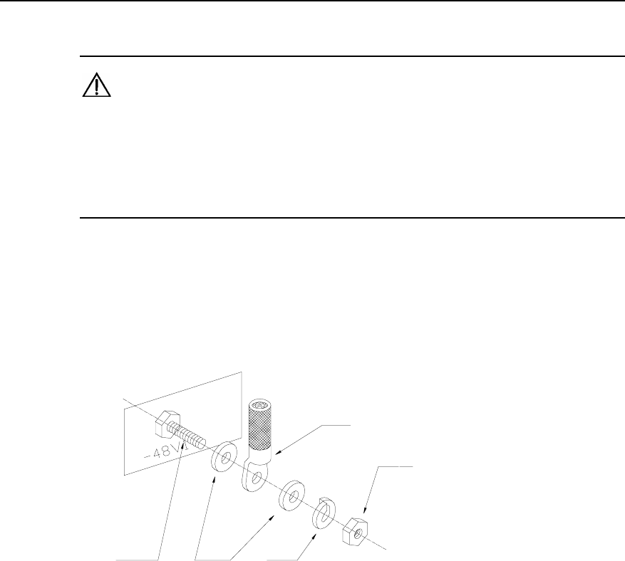
Installation Manual – BTS3606 Cabinet Installation
Airbridge BTS3606&3606A CDMA Base Station Chapter 4 Installing Cables
Huawei Technologies Proprietary
4-17
III. Connecting Power Cables to the Power Distribution Cabinet
Caution:
z If the power supply is on during the operation, do not touch the binding posts with
the adjustable wrench or the screwdriver. Make sure to wrap the wrench with
insulating tape.
z The installation of all lugs is the same.
To connect the power cable to the power distribution cabinet, proceed as follows:
1) Connect the OT terminal of the power cable to the corresponding binding post on
the power distribution cabinet.
2) Add common washers and spring washers, as shown in Figure 4-13.
(1)
(2)
(3) (4) (5)
(1) Cable (2) Screw cap (3) Wiring screw rod
(4) Washer (5) Spring washer
Figure 4-13 Fixing the power cable
3) Fix the lugs.
z When several OT terminals of power cables must be connected to a binding post,
the lugs must not be overlapped. Connect them in a cross manner or
back-to-back mode, as shown in Figure 4-14.
z If overlapping cannot be avoided, bend the lugs at an angle of 45 degrees or 90
degrees and put the bigger lug under the smaller one, as shown in Figure 4-14.
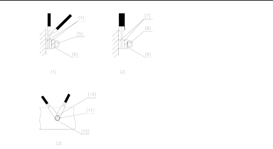
Installation Manual – BTS3606 Cabinet Installation
Airbridge BTS3606&3606A CDMA Base Station Chapter 4 Installing Cables
Huawei Technologies Proprietary
4-18
(1) Bent by 45°or 90° (2) Back-to-back installation (3) Cross-installation
(4) Plain washer (5) Nut (6) Spring washer
(7) Plain washer (8) Nut (9) Spring washer
(10) Plain washer (11) Nut (12) Spring washer
Figure 4-14 Cross-connection of power cables
4.3.3 Routing Power Cables
Route power cables according to the principles below:
z Bind the –48 V power cable and the GND cable together.
z Separate the power cables from other cables. Never bind them with other
cables.
z Measure the accurate distance from the connecting terminal of the power input
to the power distribution box before cabling.
z Make sure the cables are long enough and preserve redundant length. If the
cables are not long enough, stop distributing and use new ones. It is prohibited
to make tie-in or welding points on the cables, as shown in Figure 4-15.
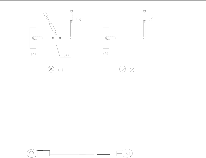
Installation Manual – BTS3606 Cabinet Installation
Airbridge BTS3606&3606A CDMA Base Station Chapter 4 Installing Cables
Huawei Technologies Proprietary
4-19
(1) Wrong (2) Correct (3) To BTS
(4) Weld (5) Grounding copper bar or power copper bar
Figure 4-15 Wrong operation versus correct operation
4.4 Installing Cabinet Protection Grounding Cables
Both ends of the protection grounding cable for the cabinet are OT terminals (also
called lugs). Figure 4-16 shows the outlook of the protection grounding cable.
Figure 4-16 Outlook of the protection grounding cables of the cabinet
4.4.1 Preparing Cabinet Protection Grounding Cables
The two wiring terminals of the protection grounding cable are made on site. The
method to prepare them is the same as that of the power cables. See section 4.3.1
“Preparing Power Cables”.
Determine the length of the grounding cables according to their actual cabling path,
that is, the route from the binding post of BTS3606 cabinet to the wiring holes of the
grounding protection bar of the cabinet.
4.4.2 Connecting Cabinet Protection Grounding Cables
To connect the cable, proceed as follows:
1) Connect one OT terminal of the cabinet protection grounding cable to PE
grounding bar on top of the BTS3606 cabinet
2) Route the cable along the cable rack

Installation Manual – BTS3606 Cabinet Installation
Airbridge BTS3606&3606A CDMA Base Station Chapter 4 Installing Cables
Huawei Technologies Proprietary
4-20
3) Connect the other end to the corresponding hole of the protection grounding bar
in the cabinet.
4.4.3 Distributing Protection Grounding Cables for Cabinets
The protection grounding cable for cabinet is distributed in the same way as the
power cable is. See section 4.3.3 , “Routing Power Cables”.
4.5 Installing Optical Fibers
When the BTS3606 connects to the ODU3601C, you need to install the optical fibers.
4.5.1 Distribution Principle of Optical Fibers
Observe the following principles when distributing and binding optical fibers:
z Do not bend an optical fiber to a right angle upon distribution. Make it round with
a diameter of no less than 8 cm. Optical fiber pairs must be bound in order.
z The optical fibers between cabinets can be distributed through the cabling rack,
or directly on the top of the cabinet for the consideration of a nice appearance.
z Keep the redundant optical fibers in the fiber management tray. Do not twist and
mix fibers; otherwise, it is difficult to identify them.
z Optical fibers must be distributed according to specific conditions and bound
properly. Those fixed onto the beam must be bound with the interval of 150 mm.
z Corrugated plastic tubes must be added to protect the fibers when they are led
out of the cabling rack.
4.5.2 Installing Optical Fibers to ODU3601C
When BTS3606 is connected with ODU3601C, optical fibers are led out from CCPMs
to the MTRM of ODU3601C.
4.5.3 Installing Optical Fibers of Combined Cabinets
For details, see 4.8.2 "Installing Optical Fiber".
4.6 Installing E1/T1 Trunks
This section introduces the DB25 connectors of E1/T1 trunks on cabinet top and the
installation procedure of E1/T1 trunks.
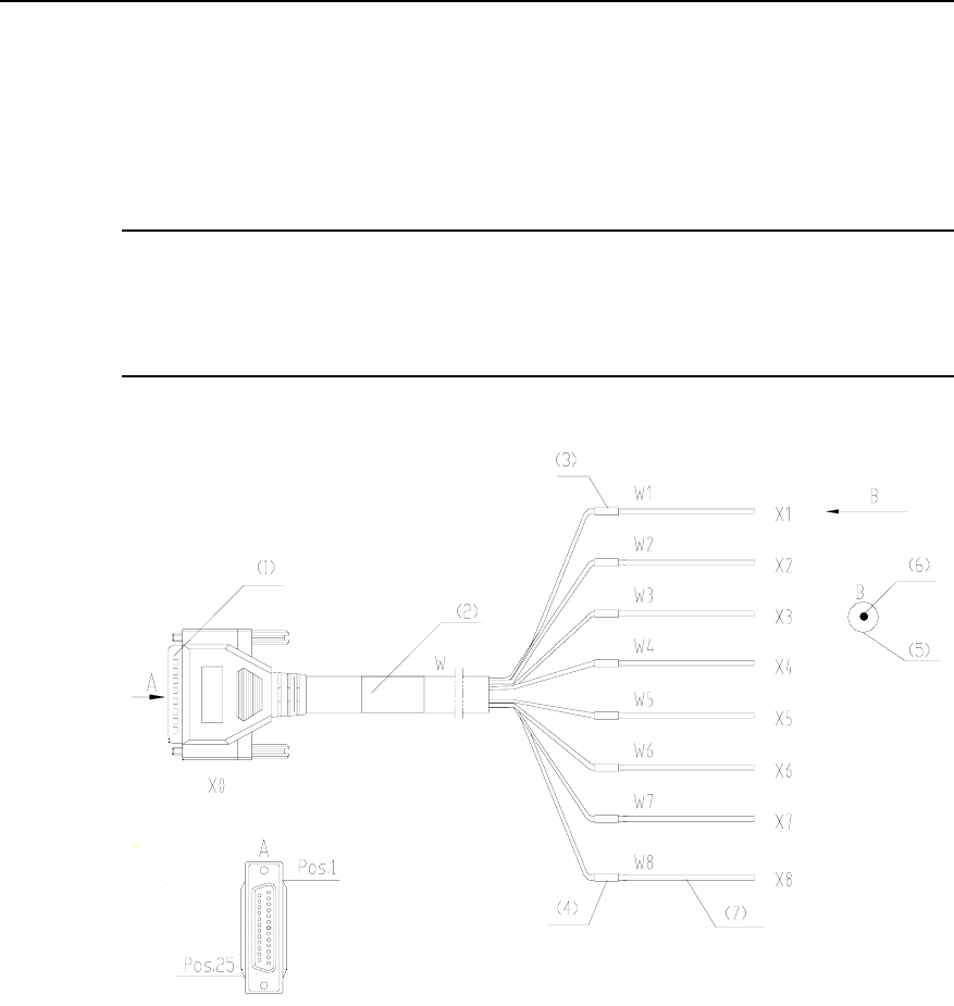
Installation Manual – BTS3606 Cabinet Installation
Airbridge BTS3606&3606A CDMA Base Station Chapter 4 Installing Cables
Huawei Technologies Proprietary
4-21
4.6.1 Introduction to E1/T1 Trunks
The E1/T1 trunks are used to connect the E1 lightning protection board and
transmission interface box. Figure 4-17 shows the 75 Ω coaxial E1/T1 trunks.
Note:
The appearance of the 120 Ω E1/T1 trunk is the same with that of the 75 Ω E1/T1
trunk.
(1) DB25 connector (X0) (2) Main label (3) Assistant label 1 (4) Assistant label8
(5) External conductor of coaxial trunk (Ring, namely, braid layer)
(6) Core of coaxial trunk (Tip) (7) 75 Ω coaxial trunk (X1–X8)
Figure 4-17 75 Ω E1/T1 trunks
When installing E1/T1 trunks, pay attention to the correspondence between the E1
cable and DB25 connector. Table 4-4 describes the correspondence between the E1
cable and DB25 connector.

Installation Manual – BTS3606 Cabinet Installation
Airbridge BTS3606&3606A CDMA Base Station Chapter 4 Installing Cables
Huawei Technologies Proprietary
4-22
Table 4-4 Correspondence between the E1 cable and DB25 connector
Cable No. Initial PIN End PIN Label Remarks
X0.24 X1.Tip
W1 1 X0.25 X1.Ring
CHAN 0 TX
X0.13 X2.Tip
W2 2 X0.12 X2.Ring
CHAN 0 RX
CHAN 0
X0.11 X3.Tip
W3 3 X0.10 X3.Ring
CHAN 1 TX
X0.9 X4.Tip
W4 4 X0.8 X4.Ring
CHAN 1 RX
CHAN 1
X0.7 X5.Tip
W5 5 X0.6 X5.Ring
CHAN 2 TX
X0.5 X6.Tip
W6 6 X0. 4 X6.Ring CHAN 2 RX
CHAN 2
X0.3 X7.Tip
W7 7 X0.2 X7.Ring
CHAN 3 TX
X0.14 X8.Tip
W8 8 X0.15 X8.Ring
CHAN 3 RX
CHAN 3
4.6.2 Introduction to DB25 Connectors
There are four external DB25 connectors on the E1 lightning protection board on the
cabinet top. Each connector can connect four E1 cables.
The four DB25 connectors are numbered E1_0, E1_1, E1_2, and E1_3 from the front
to the back.
E1_0 and E1_1 correspond to the BCIM in Slot 0, and E1_2, E1_3 to the BCIM in
Slot 1.
4.6.3 Installation Procedure
To install E1/T1 trunks, proceed as follows:
1) Determine the number of DB25 connectors according to the number of T1/T1
trunks configured.
z Select E1_0 if there are not more than four trunks.

Installation Manual – BTS3606 Cabinet Installation
Airbridge BTS3606&3606A CDMA Base Station Chapter 4 Installing Cables
Huawei Technologies Proprietary
4-23
z Select E1_0, E1_1, and E1_2 if there are more than four but less than
twelve trunks.
2) Lead E1/T1 trunks from DB25 connector on E1 lightning protection board to the
cable ladder on top of the cabinet.
3) Route them to the digital distribution frame (DDF) along the cable ladder.
4) Bundle the trunks as required.
Note:
z An E1/T1 trunk is composed of two coaxial cables. Generally, four E1/T1 cables
form a transmission cable that connects E1 lightning protection board on the top of
the cabinet through DB25 connector. Pay attention to the installation sequence
and avoid cross-connection when connecting coaxial cables on the DB25
connector.
z Multiple BTSs can form star, chain, or tree topology. In this case, connect E1/T1
trunks according to configurations of the software. For details, see related
engineering documents.
4.7 Installing EAC Cables
This section introduces the following contents:
z Connecting Power Cables to the Top of the BTS3606 Cabinet
z Connecting Data Cable
z Connecting Shared Grounding Cable
z Setting User-Defined Extended Port
For other cable connections and settings of the EAC, see the documentation
delivered with the EAC.
4.7.1 Connecting Power Cables to the Top of the BTS3606 Cabinet
Figure 4-18 shows the wiring terminal of a power cable of the EAC.
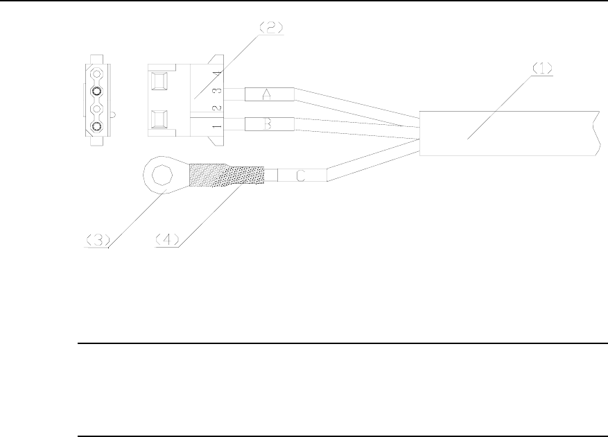
Installation Manual – BTS3606 Cabinet Installation
Airbridge BTS3606&3606A CDMA Base Station Chapter 4 Installing Cables
Huawei Technologies Proprietary
4-24
(1) Power cable (2) 2P horizontal connector base
(3) Naked crimping connector (4) Heat-shrinkable tube
Figure 4-18 Structure of an EAC power cable
Note:
The letters A, B, C as shown in Figure 4-18 are not cable labels. They are used for
the convenience of installation description.
To connect power cables, proceed as follows:
1) Connect the OT terminal of cable C (yellow green) as shown in Figure 4-18 to
the grounding screw of the PE grounding bar as shown in Figure 4-19
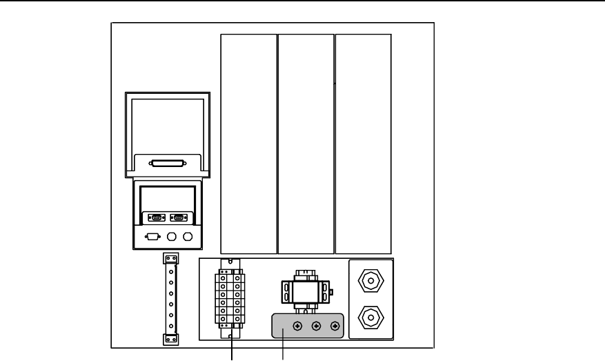
Installation Manual – BTS3606 Cabinet Installation
Airbridge BTS3606&3606A CDMA Base Station Chapter 4 Installing Cables
Huawei Technologies Proprietary
4-25
E1_0~7
EXT_CLK EAC
ALARM GPS0 GPS1
(1) (2)
(1) Wiring terminal (2) PE grounding bar
Figure 4-19 Position of the PE grounding bar
2) Remove the 2P horizontal connector base as shown in Figure 4-18.
3) Strip the shielding layer at the ends of cable A and cable B as shown in Figure
4-18 for 1.5 cm till cable cores are exposed.
4) Insert the naked cable cores to the –48 V cable connection hole and GND cable
connection hole respectively at the top of the cabinet, as show in Figure 4-20.
z Cable A (The label is blue, marked with P–): Connected to the –48 V cable
connection hole.
z Cable B (The label is red, marked with P+): Connected to the GND cable
connection hole.
5) Tighten the screws on the wiring terminals.
4.7.2 Connecting Data Cable
To connect a data cable, proceed as follows:
1) Connect the 25-pin connector of the data cable to the EAC.
2) Connect the 9-pin connector of the data cable to DB9 socket marked as “EAC"
on the compact-BTS serial port lightningproof module (CSLM) on the top of the
BTS3606 cabinet.
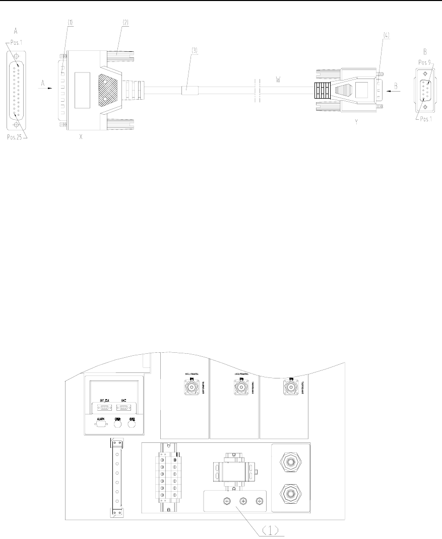
Installation Manual – BTS3606 Cabinet Installation
Airbridge BTS3606&3606A CDMA Base Station Chapter 4 Installing Cables
Huawei Technologies Proprietary
4-26
(1) 25-pin connector (2) #4-40 screw (3) Label (4) 9-pin connector
Figure 4-20 Structure of the EAC data cable
4.7.3 Connecting Shared Grounding Cable
To connect the shared grounding cable, proceed as follows:
1) Connect one end of the cable to the working ground of the EAC.
2) Connect the other end of the cable to the PE grounding copper bar on the top of
the cabinet, as shown in Figure 4-21.
In this way, the EAC can share the same grounding with the BTS equipment.
(1) PE grounding bar
Figure 4-21 Top sectional view of the cabinet
4.7.4 Setting User-Defined Extended Port
You can define the EAC extended port and query the setting.

Installation Manual – BTS3606 Cabinet Installation
Airbridge BTS3606&3606A CDMA Base Station Chapter 4 Installing Cables
Huawei Technologies Proprietary
4-27
I. Setting EAC Extended Port
To set the EAC extended port, proceed as follows:
1) Start the Service Maintenance System or run the Telnet.
2) Enter the command SET CBTSEACEXTALM in the command input box.
3) Press <Enter>.
4) Enter the information including the BTS Name, BTS ID, and IO ID (extended port
number).
5) Select the Operate Mode.
6) Enter the alarm information if the Operate Mode is set to DEF.
7) Press F9 to execute the command.
II. Querying EAC Extended Port
To query the setting of the EAC extended port, proceed as follows:
1) Start the Airbridge BTS3606 Maintenance System or run the Telnet.
2) Enter the command DSP CBTSEACEXTALM in the command input box.
3) Press <Enter>.
4) Enter the BTS Name and BTS ID.
5) Press <F9> to execute the command.
4.8 Installing Cables of Combined Cabinets
When BTS3606 cabinets are combined, you need to install RS485 serial port cables,
optical fibers, and 10 MHz clock cables.
Note:
Before connecting cables of combined cabinets, check that the TMCM is inserted into
the slot of the BCKM at the upper half part of the combined subrack, and the LECM
into the slot of the CTRM.
4.8.1 Installing RS485 Serial Port Cable
To install an RS485 serial port cable, proceed as follows:
1) Remove the rear door from the extension cabinet.
2) Remove the serial port cable from the DB26 socket on the upper/lower RF
backplane.
3) Connect one end of the RS485 serial port cable to the DB26 socket on the upper
RF backplane.
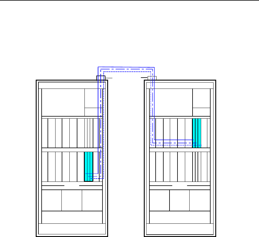
Installation Manual – BTS3606 Cabinet Installation
Airbridge BTS3606&3606A CDMA Base Station Chapter 4 Installing Cables
Huawei Technologies Proprietary
4-28
4) Connect the other end to the DB9 socket of the power backplane.
4.8.2 Installing Optical Fiber
When BTS3606 cabinets are combined, you can connect optical fibers between the
basic cabinet and extension cabinet as shown in Figure 4-22.
CDDU Switch
box
Fan box
C
C
P
M
C
C
P
M
C
C
P
M
B
C
I
M
B
C
K
M
C
C
P
M
C
C
P
M
C
C
P
M
B
C
K
M
C
H
P
A
C
T
R
M
C
H
P
A
C
T
R
M
C
H
P
A
C
T
R
M
C
H
P
A
C
T
R
M
C
H
P
A
C
T
R
M
C
H
P
A
C
T
R
M
Cable trough
Cable trough
P
S
U
P
S
U
P
S
U
Tool box
CDDU Switch
box
Fan box
L
E
C
M
L
E
C
M
L
E
C
M
T
M
C
M
C
H
P
A
C
T
R
M
C
H
P
A
C
T
R
M
C
H
P
A
C
T
R
M
Cable trough
Cable trough
P
S
U
P
S
U
P
S
U
Tool box
Basic cabinet Extension cabinet
Optical fiber
port
Figure 4-22 Connections of optical fibers between BTS3606 combined cabinets
To install an optical fiber, proceed as follows:
1) Cut an optical fiber with the required length according to the cabling mode as
shown in Figure 4-22 and note that a proper margin must be reserved.
2) Prepare the connectors of the optical fiber.
3) Connect one end of the optical fiber to LINK0 (optical interface 0) of the CCPM in
slot 1 in the basic cabinet.
4) Lead the optical fiber along the right side of the basic cabinet to the optical fiber
port on the top of the extension cabinet.
5) Lead out the optical fiber from the basic cabinet and then lead it through the
optical fiber port of the extension cabinet.
6) Connect the other end of the optical fiber to LINK (an optical interface) of the
LECM in slot 0.
7) Repeat the above steps to complete the connection of the following cables:

Installation Manual – BTS3606 Cabinet Installation
Airbridge BTS3606&3606A CDMA Base Station Chapter 4 Installing Cables
Huawei Technologies Proprietary
4-29
z The optical fiber between the CCPM in slot 3 in the basic cabinet and the LECM
in slot 2 in the extension cabinet
z The optical fiber between the CCPM in slot 5 in the basic cabinet and the
LECM in slot 4 in the extension cabinet
4.8.3 Installing GPS RF Cable
To install a GPS RF cable, proceed as follows:
1) Choose a cable with one end connected to the GPS_1 connector on the top of
the basic cabinet. The cable is marked with GPS_1.
2) Connect the other end of the cable to the 10 M interface of the BCKM.
3) Measure the distance between the GPS_1 connectors of the basic and
extension cabinets.
4) Cut the GPS RF cable as needed according to the measured distance.
5) Prepare the connectors of the GPS RF cable.
The two ends of the cable are connected to the GPS_1 connectors of the basic
and extension cabinets respectively.
6) Choose a cable with one end connected to the GPS_1 connector on the top of
the extension cabinet. The label of the cable is marked with GPS_1.
7) Connect the other end of the cable to the 10 M IN interface of the TMCM.
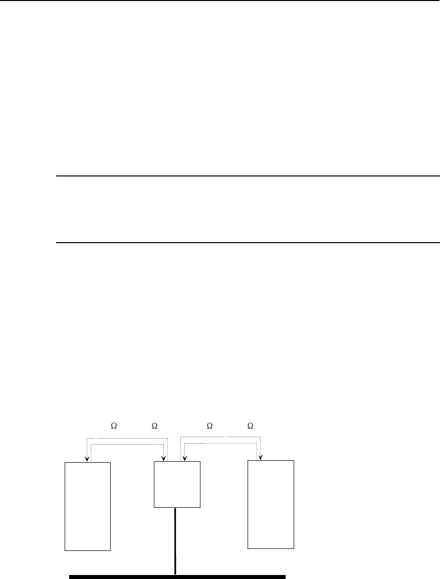
Installation Manual – BTS3606 Cabinet Installation
Airbridge BTS3606&3606A CDMA Base Station Chapter 5 Installing Digital Distribution Frame
Huawei Technologies Proprietary
5-1
Chapter 5 Installing Digital Distribution Frame
The digital distribution frame (DDF) is an indoor transmission interface box. There are
two types of DDF applicable to the BTS3606: 120Ω DDF and 75Ω DDF.
This chapter describes how to install and use these two types of DDF.
Note:
For structure, components, and specifications of the DDF, see Airbridge
BTS3606&3606A CDMA Base Station Hardware Description Manual.
5.1 Installing the DDF
This section introduces the position of the DDF in the equipment room and the DDF
installation procedure.
5.1.1 Position of DDF in the Equipment Room
Figure 5-1 shows the position of the DDF and connection of trunk cables.
DDF
Transmission
equipment BTS
75 or 120
Grounding bar for equipment room
75 or 120
Figure 5-1 Position of DDF in the equipment room
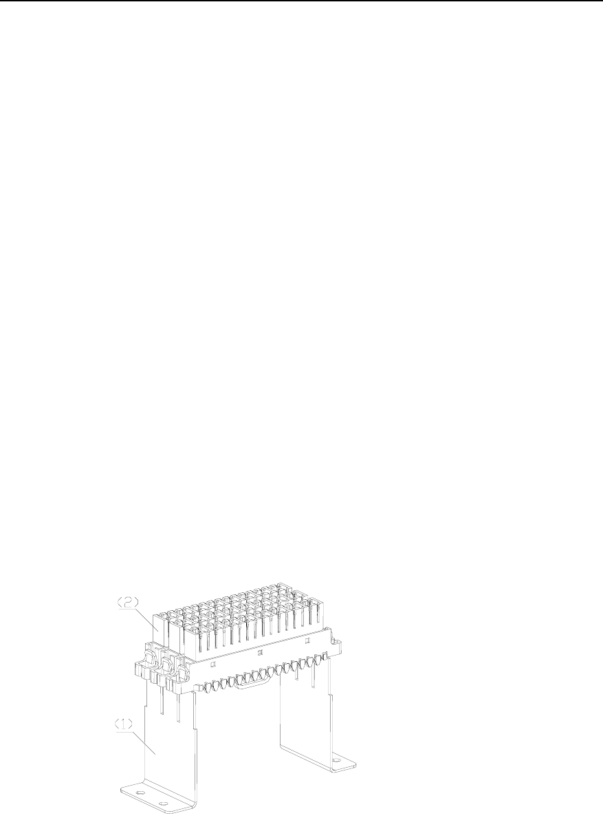
Installation Manual – BTS3606 Cabinet Installation
Airbridge BTS3606&3606A CDMA Base Station Chapter 5 Installing Digital Distribution Frame
Huawei Technologies Proprietary
5-2
5.1.2 Installation Procedure
To install the DDF, proceed as follows:
1) Determine the installation location for the DDF according to the engineering
design for the equipment room.
2) Mark the position of the DDF according to its dimensions.
3) Determine the installation holes.
4) Drive the M8 expansion bolts into the three installation holes.
5) Hang the DDF onto the expansion bolts.
6) Tighten the expansion bolts with a screwdriver.
5.2 Using 75Ω DDF
The 75Ω DDF consists of 24-channel alarm extension connector, 75Ω DDF unit, and
grounding busbar. This section describes how to install and use these components.
5.2.1 Installing 24-Channel Alarm Extension Connector
To install the 24-channel alarm extension connector, proceed as follows:
1) Unpack the 24-channel alarm extension connector.
2) Check if the component is complete according to the manifest.
3) Use bolts to fix the 24-channel alarm extension connector to the left side of the
enclosure.
4) Bind the alarm cables coming in from one side of the enclosure to the cabling
hole at the bottom of the 8-E1 module, as shown in Figure 5-2.
(1) Bracket (2) 8-E1 module
Figure 5-2 8-E1 module
5) Divide the alarm cables through the line separation tooth on the 8-E1 module.

Installation Manual – BTS3606 Cabinet Installation
Airbridge BTS3606&3606A CDMA Base Station Chapter 5 Installing Digital Distribution Frame
Huawei Technologies Proprietary
5-3
6) Lead the alarm cables to the respective slots.
7) Clamp the cables to the bracket.
8) Route the alarm cables coming in from the other side of the enclosure through
the cabling holes on both sides of the 8-E1 module and then to the respective
slots.
Note:
The identifier list of the 24-channel alarm extension connector is attached on the
cover of the enclosure. Fill it as needed.
5.2.2 Using 75Ω DDF Unit
To use the 75Ω DDF unit, proceed as follows:
1) Remove the dust-proof cover of the coaxial connector.
2) Connect the corresponding incoming and outgoing cables into the coaxial
connector.
3) Perform the loopback test for cables as needed.
5.2.3 Using the Grounding Busbar
To use the grounding busbar, proceed as follows:
1) Loose the bolt on the one end.
2) Loose the bolt on the other end.
3) Strip the ground cables.
4) Put them into the corresponding slots.
5) Fix the bolts on the two sides.
6) Fasten them by adjusting the bolts on their own slots.
5.3 Using 120Ω DDF
The 120Ω DDF consists of 24-channel alarm extension connector, 120Ω DDF unit,
and grounding busbar. This section describes how to install and use these
components.
5.3.1 Installing 24-Channel Alarm Extension Connector
The installation procedure is the same as that of the 75Ω DDF. For details, see the
section 5.2.1 “Installing 24-Channel Alarm Extension Connector”.

Installation Manual – BTS3606 Cabinet Installation
Airbridge BTS3606&3606A CDMA Base Station Chapter 5 Installing Digital Distribution Frame
Huawei Technologies Proprietary
5-4
5.3.2 Using 120Ω DDF Unit
To use the 120Ω DDF unit, proceed as follows:
1) Lead the cables into their corresponding cable-fixing troughs.
2) Fix them onto the units.
3) Remove the nameplate of the module and note the difference among the ends of
a, b, and s. "s" stands for the grounding cable.
4) Fix the nameplate back to the position.
5) Fill the identifier list according to actual conditions.
Note:
The identifier list of the 120Ω DDF unit is attached on the cover of the enclosure and
fill it as needed.
5.3.3 Using the Grounding Busbar
The installation procedure is the same as that of the 75Ω DDF. For details, see
section 5.2.3 “Using the Grounding Busbar”.
Installation Manual – BTS3606 Cabinet Installation
Airbridge BTS3606&3606A CDMA Base Station Chapter 6 Checking Cabinet Installation
Huawei Technologies Proprietary
6-1
Chapter 6 Checking Cabinet Installation
Cabinet installation check is to review the indoor installation described in the previous
chapters.
The following items must be checked:
z Cabinet equipment
z Cable distribution
z Environment of the equipment room
z Power-on operation
z Others
6.1 Checking Cabinet Equipment
Check the following items concerning the installation of cabinet equipment.
Table 6-1 Check items for cabinet equipment installation
Item Requirement
1 The power cables, grounding cables, trunks, and RF cables are intact and
there is no tie-in on them.
2 The RF cable connectors are installed in position. Poor connection will result
in abnormal voltage standing wave ratio and affect the normal operation of
the system.
3 The rack and base/support are firmly connected. The rack is stable after
installation.
4 The connectors of the trunks are intact. They are made according to
specifications and connected securely.
5 The cables are distributed in a way to facilitate maintenance and expansion.
6 Insulating materials are used to insulate the cabinet from the ground and the
wall.
7 All the cabinet doors at the aisle are installed and aligned. The error is less
than 5 mm (0.2 in.).
8 The space between adjacent bases is equal to or less than 3 mm (0.12 in.).
9 The vertical deviation of the cabinet is less than 3 mm (0.12 in.).
10 The cables from the combiner, the divider, and CDDU to the top of the
cabinet run through the space on both sides of the cabinet.
11 Rigid cables are not cross-connected but properly stretched. They are bent
neatly and orderly with certain margin at the bending parts

Installation Manual – BTS3606 Cabinet Installation
Airbridge BTS3606&3606A CDMA Base Station Chapter 6 Checking Cabinet Installation
Huawei Technologies Proprietary
6-2
Item Requirement
12 The transverse cables inside the rack are bound at the inner part of the cross
rod, and the longitudinal cables inside the rack are bund along the cable
trough at both sides.
13 All the cables between racks are through the holes at the edge of the cabinet
and connected to the corresponding position.
14
The screws of the fan are fastened securely.
The fan can be switched on or off normally. Its rotation is normal and the
alarms can be reported normally.
15 The external antenna lightning arrester of the cabinet is correctly installed in
accordance with the design, and the connection should be reliable and in
order.
16 The cables made on site are firmly connected and in good contact. The
naked part is wrapped in insulating tape or protection tube. The connectors
of cables are firmly crimped.
17
The screws, fixing the cabinet or the base/support with the floor, are
secured.
The insulating materials, plain washers, spring washers, screws and bolts
are installed in order.
18 When leveling the base by adjusting bolts, use washers to enlarge the stress
surface area to avoid distortion of the base.
19 The upper surface of the antistatic floor in the equipment room is lower than
the lower surface of the base so as not to affect heat dissipation of the base.
20 The mechanical parts of the cabinet are correctly installed.
21 The environment alarm collection cables connected to BTS are equipped
with reliable lightning protection devices.
22
Cable labels are filled in and attached according to the specifications. The
labels are neatly arranged in the same direction.
They can be uniformly prepared as per the requirements of users for the
convenience of query. It is recommended to attach labels 2cm (0.8 in.) away
from the connector.
23 The cables are bundled neatly. The interval between cable ties are even.
The cables are properly fastened. The direction of the cable ties are the
same. All the cable ties are cut without sharp ends
24 PVC troughs are installed for the power cables and signal cables of the
alarm box on the wall. Redundant cables are coiled up and placed under the
floor of the alarm box or on the wiring ladder.
25 No part of the rack is distorted.
26 Dummy panels are installed for empty slots.
27
The boards can be inserted or removed smoothly.
The screws (if any) on the panel of the board are properly fastened, and the
spring wire is intact.
Installation Manual – BTS3606 Cabinet Installation
Airbridge BTS3606&3606A CDMA Base Station Chapter 6 Checking Cabinet Installation
Huawei Technologies Proprietary
6-3
Item Requirement
28 The jumpers on the cabling rack are routed by layer and by sector.
29 The alarm box is correctly installed according to the design. The panel is
clean without obvious damage.
30
The idle ports on the combiner, divider, or CDDU are screwed with proper
terminals.
The unused terminals on top of the cabinet are protected by protection tubes
from dirt and sundries.
31 Enough cables for connectors are reserved at the connecting points.
32 The rack is placed according to the design drawing.
33 The doors of the rack can be closed or opened smoothly.
34 There are no paint falling and collision damages on the cabinet. Otherwise,
the cabinet must be painted once more.
6.2 Checking Cable Distribution
Check cable distribution after finishing the cabinet equipment check.
6.2.1 Power Cables and Grounding Cables
Check the following items concerning the installation of power cables and grounding
cables.
Table 6-2 Check items for power cables and grounding cables installation
Item Requirement
1 Grounding protection measures are taken for the cabinet.
2 Adjacent cabinets are connected with an equipotential cable.
3 All power cables and grounding cables are copper core cables. The cables
are complete section of cables and there is no tie-in on them.
4
The grounding cables and power cables are connected correctly and firmly.
Plain washers, spring washers and nuts of the grounding terminal are
installed in order, and the nuts are fastened in position.
5 The copper lugs at both ends of the power cable and grounding cable are
welded or crimped firmly.
6
Rust and dirt on the grounding terminals are removed before the terminals
are connected.
After the terminals are connected, antirust and anticorrosion measures are
taken for them to ensure good contact.

Installation Manual – BTS3606 Cabinet Installation
Airbridge BTS3606&3606A CDMA Base Station Chapter 6 Checking Cabinet Installation
Huawei Technologies Proprietary
6-4
Item Requirement
7
The feeder from the tower top to the equipment room is grounded at least at
three places. That is, 1 m (39 in.) away from the platform of the tower; 1m
(39 in.) away from the outdoor cabling rack; and 1m (39 in.) away from the
feeder window.
The grounding cables are bundled firmly and waterproof measures are
taken for them.
8 Power cables and grounding cables outside the cabinet are bundled
separately from other cables.
9 Redundant part of power cables and grounding cables are removed instead
of being coiled up.
10 The positive pole of the primary power supply is connected to the ground
with the cross-section area defined in specifications.
11 The environment supervising device of BTS is firmly grounded.
12 Power cables and grounding cables are distributed to facilitate maintenance
and expansion.
13 If the tower is higher than 60 m (197 ft.), a feeder grounding clip is added in
the middle of the tower.
14 If the feeder from the tower is distributed on top of the building (or the
cabling rack) for over 20 m (66 ft.), a lightning protection grounding clip is
added on top of the building (or cabling rack).
15 The feeder grounding clip is fixed directly on the steel plate of the nearby
tower. It is made in compliance with specifications and well connected.
Antirust, anticorrosion and waterproof measures are taken for it.
16 The antenna feeder grounding cable on top of a building without the tower is
connected to the lightning protection grounding grid on the top of the nearby
building.
17 The front door of the cabinet is connected to the grounding bolt fixed on the
door through a cable. The grounding cable of the doors of the cabinet is
firmly connected.
18 The feeder is led into the room along the wall from the top of the building. If
a cabling ladder is used, it is grounded.
19 The feeder grounding cable is routed from the top down. The angle between
the cable and the feeder is 15 degrees as appropriate.
20 If GPS antenna is installed on the iron tower, there are two grounding points
outdoors.
21
Labels are filled in and stuck on power cables and grounding cables tidily
and their directions are the same.
The labels can be uniformly made according to the requirement of the user.
It is recommended that labels are stuck in places 2 cm (0.8 in.) away from
the connector.
22 The intervals between the power cable, the grounding cable and the signal
cable are more than 3 cm (0.12 in.).
Installation Manual – BTS3606 Cabinet Installation
Airbridge BTS3606&3606A CDMA Base Station Chapter 6 Checking Cabinet Installation
Huawei Technologies Proprietary
6-5
Item Requirement
23 The naked part and lugs of the power cable and the grounding cable are
wrapped with protection tube or insulating tape. The copper-core wires are
not exposed.
24 The power cable and the grounding cable are routed straight and bundled
neatly.
25 The power cables and grounding cables provided by Huawei include -48 V
power cables (blue cables), GND (BGND) cables (black or red cables), and
PGND cables (yellow-green or yellow cables).
6.2.2 Other Cables
Check the following items concerning the installation of other cables.
Table 6-3 Check items for other cables installation
Item Requirement
1 The GPS/GLONASS clock RF cables are correctly connected to the front
panel of the BCKM.
2 The RF cables on the front panel of the CDDU are correctly connected.
3 The optical fibers between the CCPM and the soft BTS are correctly
connected.
4 The cables and the connectors of the optical fibers are intact and clean. The
optical fibers are direct. The labels are correct and stuck properly.
5 The trunk and the socket are connected appropriately.
6 When BTS3606 cabinets are combined, RS485 serial port cables, optical
fibers, and GPS RF cables are connected properly. Cable connections
comply with the specifications.
6.3 Checking Room Environment
Check the following items concerning the environment of the equipment room.
Table 6-4 Equipment room environment check items
Item Requirement
1 The voltage and capacity of the DC power supply meet the long-term
operation requirements of the equipment.
2 The Power Distribution Frame (PDF) and the output current-limiting
protection of the primary power supply meet the requirements of the
equipment.

Installation Manual – BTS3606 Cabinet Installation
Airbridge BTS3606&3606A CDMA Base Station Chapter 6 Checking Cabinet Installation
Huawei Technologies Proprietary
6-6
Item Requirement
3 The grounding resistance of BTS is less than five ohm, and the resistance is
less than ten ohm in the areas where there are less than 20 days of
thunderstorm in a year.
4 The outdoor grounding bar is led to the grounding grid through a reliable
private path, and the core diameter of the grounding cable is in compliance
with specifications.
5 The E1 cables are not routed overhead from the BTS. If it is, protection
measures are taken for the overhead cables.
6 The earthquake-proof, lightning protection and bearing capacity meet the
requirements for the long-term operation of the equipment.
7
The relevant parameters of AC power supply meet the requirements for the
long-term operation of the equipment.
There are lightning protection units for the AC power supply system, and
they are securely connected with the ground.
8 The ambient temperature and the relative humidity of the equipment room
meet the requirements for long-term operation of the equipment.
9 There are fireproof devices in the equipment room.
10 It is recommended the metal mechanical parts associated with BTS
equipment are grounded.
11 The equipment room is far away from strong electrical field, intense
magnetic field, strong electric wave and excessive heat source to meet the
requirement in electromagnetic level.
12 The low-voltage power cables are buried and led into the mobile
communication site.
13 When the power distribution transformer is in the communication site, its
grounding grid must be combined with that of the equipment room into an
integrated one.
14 The grounding grids of the iron tower and equipment room are combined
into an integrated one.
15 The working ground, the protection ground of the communication equipment
in the site, and the lightning protection ground of the building share one
group of grounding body.
6.4 Power-on Check
Before switching on the primary power supply, use a multimeter to check the power
supplies on top of the cabinet and the grounding wiring terminals. Make sure no short
circuit exists.
Installation Manual – BTS3606 Cabinet Installation
Airbridge BTS3606&3606A CDMA Base Station Chapter 6 Checking Cabinet Installation
Huawei Technologies Proprietary
6-7
6.4.1 Power-on Check of Power Modules
I. Procedure
To carry out the power-on check of power module, proceed as follows:
1) Make sure that all the power modules are well connected with the backplanes, and
that other boards and modules (such as the CTRM and CHPA) are not inserted in
the slots of the backplanes.
2) Make sure that the primary power supply of the rectifier is on.
3) Switch on the power module.
II. Requirements
Check the following items after the power module is switched on.
Table 6-5 Power-on check items of power modules
Item Requirement
1 The output voltage of the secondary power supply is normal.
2 Indicators of all power modules are normal.
3 The output voltages of the power modules at the test point are stable and
within the range. (If not, switch off the primary power supply, clear the fault,
and power on again until they are normal.)
6.4.2 Power-on Check of Integrated Equipment
I. Procedure
To carry out the power-on check of the integrated equipment, proceed as follows:
1) Switch off all the power switches on the switch box and make sure all boards and
modules are inserted in the slots of the backplanes.
2) Switch on the power switches one by one to power on the boards and modules.
II. Requirements
All boards and modules are running normally.
Switch off the power supply immediately if any fault occurs. Power on all the boards and
modules again after the fault is cleared.
If all the boards and modules are normal, the preliminary check is passed.
6.5 Others
Check the following items in the end.
Installation Manual – BTS3606 Cabinet Installation
Airbridge BTS3606&3606A CDMA Base Station Chapter 6 Checking Cabinet Installation
Huawei Technologies Proprietary
6-8
Table 6-6 Other check items after BTS3606 installation
Item Requirement
1 Self filing check: The engineering supervisor does not submit self-test report
on quality of the engineering hardware.
2 Self standard check: If the self-test score is two or more points less than the
score given by Huawei, more points will be deducted.
3
Check whether the installation is performed according to:
z Design document
z Installation manual
z Installation requirements that are accepted by the user before kickoff but
do not meet the Huawei requirements
4 Gaps on the floor around the rack are blocked up. There are no cable ties,
screws, and other sundries on the floor.
5 The equipment room is clean and neat. Sundries such as rejected packing
boxes are cleared up. Spare parts after installation are stacked in order.
6 Boards are unpacked and plugged in accordance with the antistatic
specifications.
7 Tools for installation are in compliance with antistatic requirements.
8 Signal cables for expansion are bundled or connected to the reserved
position in the cabinet to facilitate expansion and maintenance.

Installation Manual – BTS3606 Cabinet Installation
Airbridge BTS3606&3606A CDMA Base Station Index
Huawei Technologies Proprietary
i-1
Index
A
anchor bolt, 2-15
B
baseband board
BCIM, 3-5
BCKM, 3-5
CCPM/CECM, 3-5
C
cabinet assembly
A600 support, 2-3
lower support, 2-2
U-bar support, 2-4
cabinet configuration, 3-4
cabinet door
left-front and right-front doors, 3-4
rear door, 3-3
side door, 3-4
cabinet layout,principle, 2-5
checking cabinet equipment, 6-1
checking cable distribution, 6-3
checking room environment, 6-5
conducting insulation test, 2-11
D
DDF
120Ω DDF, 5-1
75Ω DDF, 5-1
installation procedure, 5-2
position, 5-1
disassembling expansion bolt, 2-9
drill bit, 2-8
drilling hole, 2-8, 2-13, 2-14, 2-20
E
expansion bolt, 2-8
F
fixing lower support, 2-9
flowchart of
installing assembly on antistatic floor, 2-12
installing assembly on cement floor, 2-6
installing assembly on cement floor with poor
bearing capacity, 2-17
H
height-lock bolt, 2-15
I
installation condition
auxiliary equipment, 1-4
construction condition, 1-3
environment condition, 1-3
grounding condition, 1-4
load-bearing capacity, 1-3
power supply condition, 1-4
installation preparation, 1-1
installation procedure
checking cabinet installation, 6-1
installing cabinet and cabinet equipment, 3-1
installing cabinet assembly, 2-1
installing digital distribution frame, 5-1
installing 24-channel alarm extension connector, 5-2
installing assembly
on antistatic floor, 2-11
on cement floor, 2-6
on cement floor with poor bearing capacity, 2-17
installing baseband board, 3-5
installing cabinet, 3-1
installing equipment in extension cabinet

Installation Manual – BTS3606 Cabinet Installation
Airbridge BTS3606&3606A CDMA Base Station Index
Huawei Technologies Proprietary
i-2
LECM, 3-9
TMCM, 3-9
installing expansion bolt, 2-9
installing or removing cabinet door, 3-3
installing other functional module, 3-9
installing power module, 3-8
installing RF module, 3-7
insulating covering, 2-10
insulating plate, 2-9
insulating washer, 2-8
insulation test, 2-11
L
leveling lower support, 2-10
M
M12%60 bolt, 2-10
M12×70 bolt, 2-8
O
other check item, 6-8
P
plain washer, 2-8
positioning the cabinet, 2-7
power-on check, 6-6
integrated equipment, 6-7
power module, 6-7
preparing U-bar support, 2-19
project file, 1-1
R
removing floor framework, 2-13
RF module
CDDU, 3-7
CHPA, 3-7
CMPA, 3-7
CMTR, 3-7
CTRM, 3-7
S
spring washer, 2-8
T
tool and instrument, 1-1
U
unpacking
unpacking carton, 1-8
unpacking requirement, 1-4
unpacking wooden case, 1-6
using 120Ω DDF unit, 5-4
using 75Ω DDF unit, 5-3
using grounding busbar, 5-3
i.