Huawei Technologies CRFU-800AB CDMA Radio Frequency Unit User Manual
Huawei Technologies Co.,Ltd CDMA Radio Frequency Unit
Installation Manual

1
CRFU Maintenance Guide
Issue 02 Date 2008-11-30
Huawei Technologies Co., Ltd. provides customers with comprehensive technical support and service. For
any assistance, please contact our local office or company headquarters.

2
Huawei Technologies Co., Ltd.
Address: Huawei Industrial Base
Bantian, Longgang
Shenzhen 518129
People's Republic of China
Website: http://www.huawei.com
Email: support@huawei.com
Copyright © Huawei Technologies Co., Ltd. 2008. All rights reserved.
No part of this document may be reproduced or transmitted in any form or by any means without prior
written consent of Huawei Technologies Co., Ltd.
Trademarks and Permissions
and other Huawei trademarks are the property of Huawei Technologies Co., Ltd. All other
trademarks and trade names mentioned in this document are the property of their respective holders.
Notice
The information in this document is subject to change without notice. Every effort has been made in
the preparation of this document to ensure accuracy of the contents, but the statements, information,
and recommendations in this document do not constitute a warranty of any kind, express or implied.
Contents
1 Replacing the CRFU ...................................................................................................................3
Step 1 Record information of the carriers. .................................................................................4
Step 2 Block the carriers.........................................................................................................4
Step 3 Power off the AC surge protection box...................................................................5
Step 4 Remove the faulty CRFU............................................................................................5
Step 5 Install the new CRFU..................................................................................................6
Step 6 Power on the AC surge protection box....................................................................6
Step 7 Load the CPU software and FPGA software of the RRU3606..............................6
3
Step 8 Unblock the carriers....................................................................................................7
Step 9 Ensure that the new CRFU module is functional..................................................7
Postrequisite.........................................................................................................................................7
1 Replacing the CRFU
This describes how to replace the faulty CRFU. The CRFU implements the
RF processing function of the BTS.
Prerequisite
The following tools and materials are available: the ESD wrist strap, Phillips
screwdriver, ESD box or bag, torque wrench, and keys to the front panel and
cabinet door.
The new CRFU is available. Ensure that it is intact and its hardware version
is consistent with the faulty CRFU.
Context
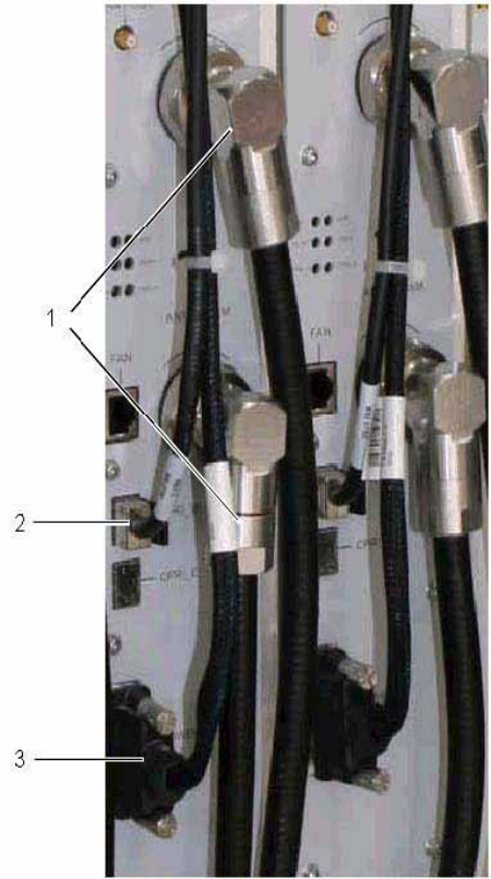
Figure 1-1 shows cable connections of the CRFU
4
(1) RF jumpers
(2) Cable connected to the CPRI port
(3) (3) Power cable
Procedure
Step 1 Record information of the carriers.
Run the DSP CBTSSECTORCARRIERINFO command to query the cell IDs,
sector IDs, and carrier IDs.
Step 2 Block the carriers.
1. Run the BLK RES command to block all carriers of the sectors where the
CRFU is located. The recommended priority value is "low".
2. Run the DSP RES command to query whether the carriers are blocked. If
the carriers are blocked, proceed with the next step.
5
Step 3 Power off the AC surge protection box.
Set the air-break switch controlling the CRFU on the DCDU to OFF.
Step 4 Remove the faulty CRFU.
1. Remove faulty cables of the CRFU.
Disconnect power cables of the CRFU and attach temporary labels to the removed
power cables.
Use a torque wrench to loosen the DIN 7/16 angle male connector of the RF
jumper, disconnect the RF jumper, and attach temporary labels to the RF jumper.
Remove the CPRI-port cables from the CRFU and attach temporary labels to the
CPRI-port cables.
2. Loosen the CRFU screws.
Use a Phillips screwdriver to loosen the fastening screws of the CRFU.
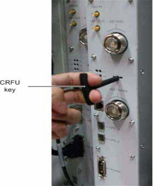
3. Dismantle the CRFU Use the key to the front panel to dismantle
the CRFU, as shown in Figure 1-2.
Figure 1-2 Use the key to the front panel to dismantle the CRFU
6
Step 5 Install the new CRFU.
1. Install the CRFU.
Push the new CRFU along the guide rail into the subrack.
2. Fasten the CRFU screws.
3. Connect the CRFU cables.
Insert the connector of the CPRI-port cable into the CPRI_0 port
of the CRFU according to the temporary labels.
Insert the DIN 7/16 angle male connector of the RF cable into the ANT
port of the CRFU and use a torque wrench to tighten the DIN angle
male connector. The force moment ranges 25 N·m to 35 N·m.
Install power cables of the CRFU and tighten the screws.
Step 6 Power on the AC surge protection box.
Set the air-break switch controlling the CRFU on the DCDU to ON.
Step 7 Load the CPU software and FPGA software of the RRU3606.
7
If the automatic loading function is enabled for the
RRU3606, the RRU3606 automatically loads software
from the BAM.
If the auto-loading function of the RRU3606 is
disabled, run the DLD CBTSSW command to load the
software.
Step 8 Unblock the carriers.
Run the UBL RES command to unblock the carriers.
Step 9 Ensure that the new CRFU module is functional.
RUN indicator: ON for 1s and OFF for 1s.
----End
Postrequisite
After replacing the CRFU, perform the following steps:
1. Record the software version, board name, slot number, and site name of the
faulty board.
2. Check whether there is visible physical damage on the board, for example,
mechanical parts or plug-ins are distorted, pins are bent or missing, or the board is
burnt.
3. Record the information about the fault location process, including the cause
of the fault, fault symptoms, alarm name, status of indicators on the board panel,
and detailed procedures for identifying and clearing the fault on site.
4. Place the faulty board in an antistatic bag. Then, place the onsite fault record
and the antistatic bag in the board box, and store them properly.