Huawei Technologies DRH3985A Distributed Remote Head User Manual Installation Guide
Huawei Technologies Co.,Ltd Distributed Remote Head Installation Guide
UserManual.wiki
>
Huawei Technologies
>
DRH3985A User Manual
>
User Manual II
Contents
1.
User Manual
2.
User Manual II
3.
User Manual III
User Manual II
Navigation menu
Upload a User Manual
Namespaces
Wiki Guide
HTML
PDF
Info
Views
User Manual
Discussion / Help
Navigation
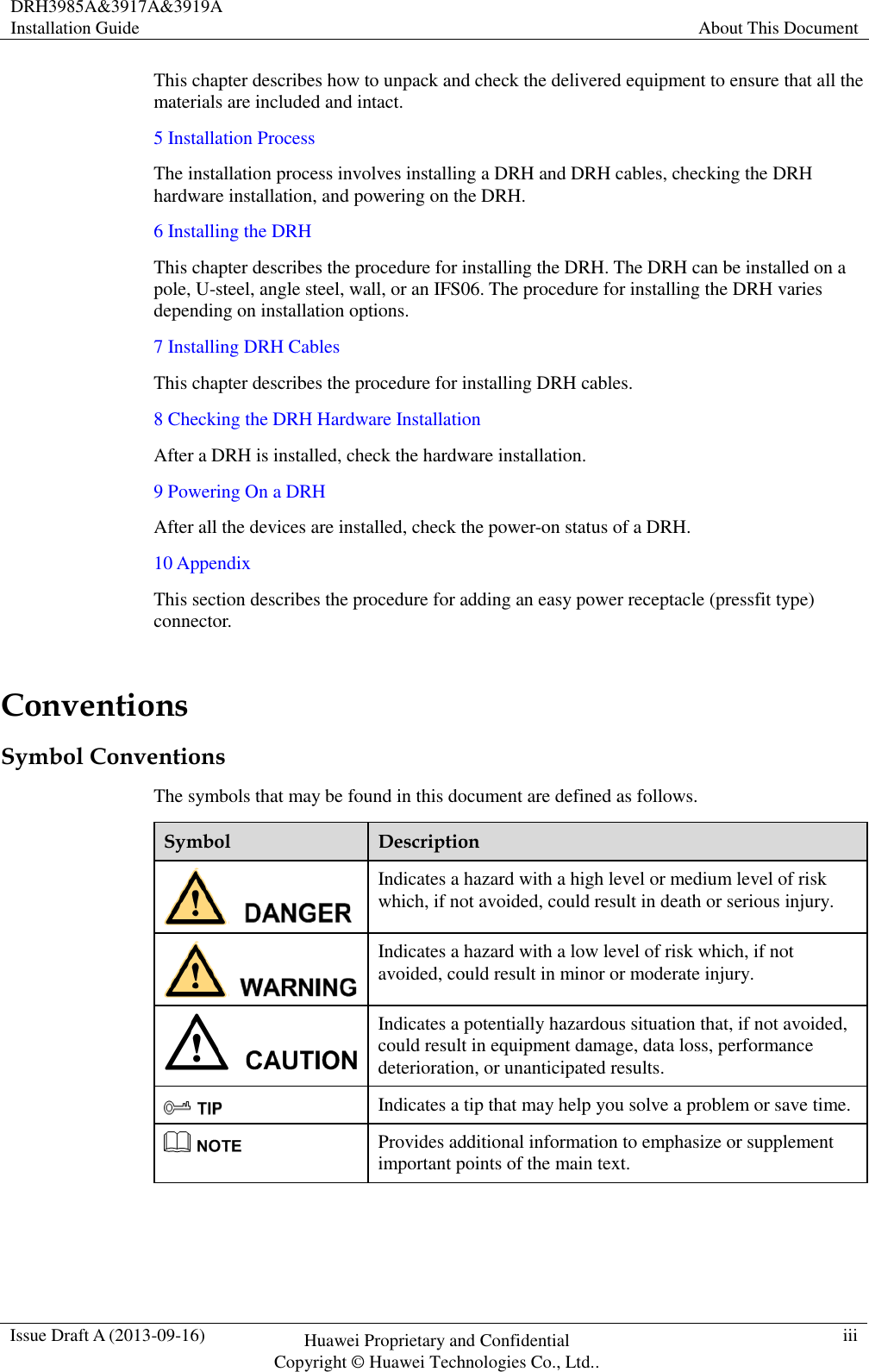
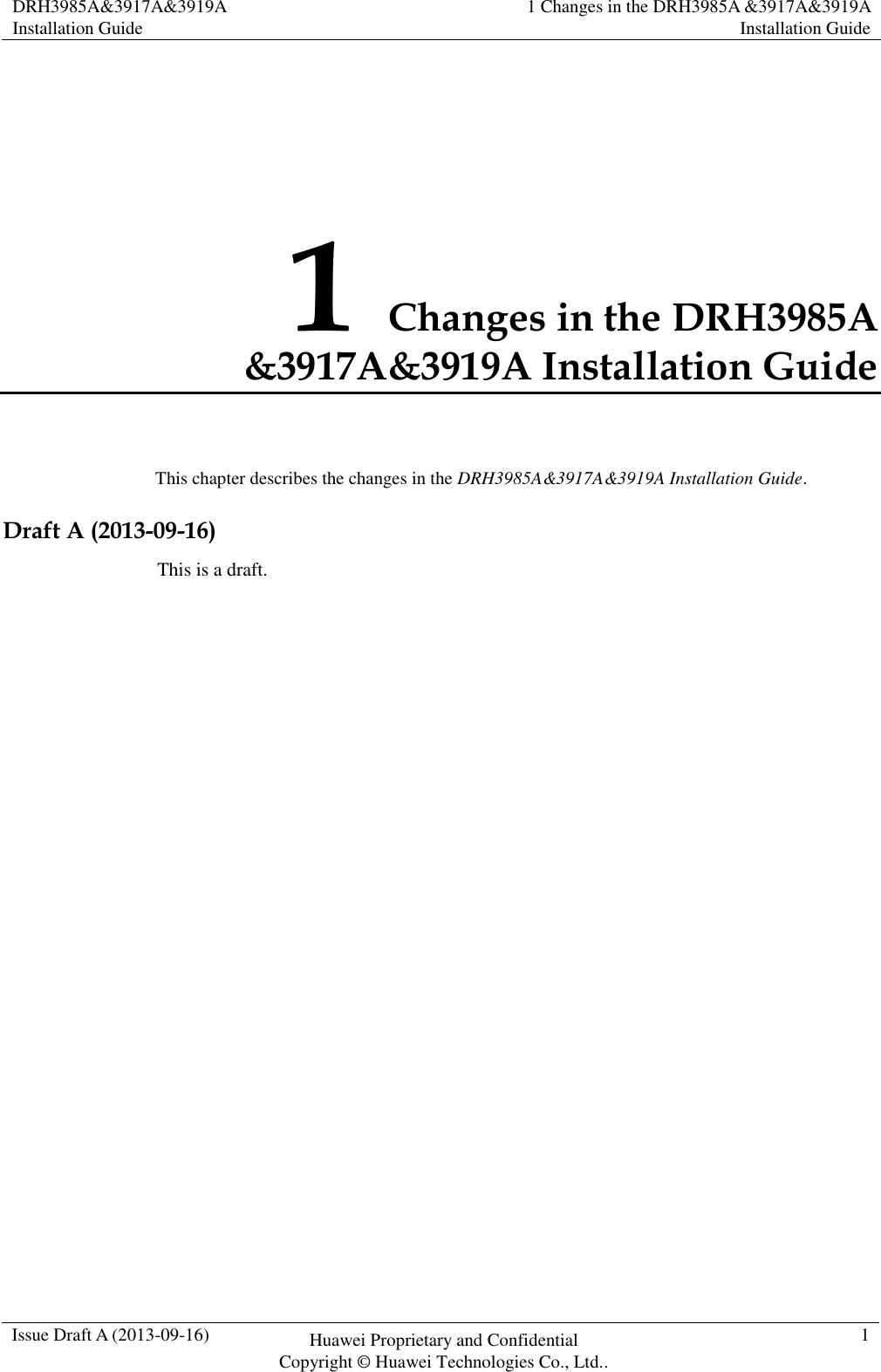
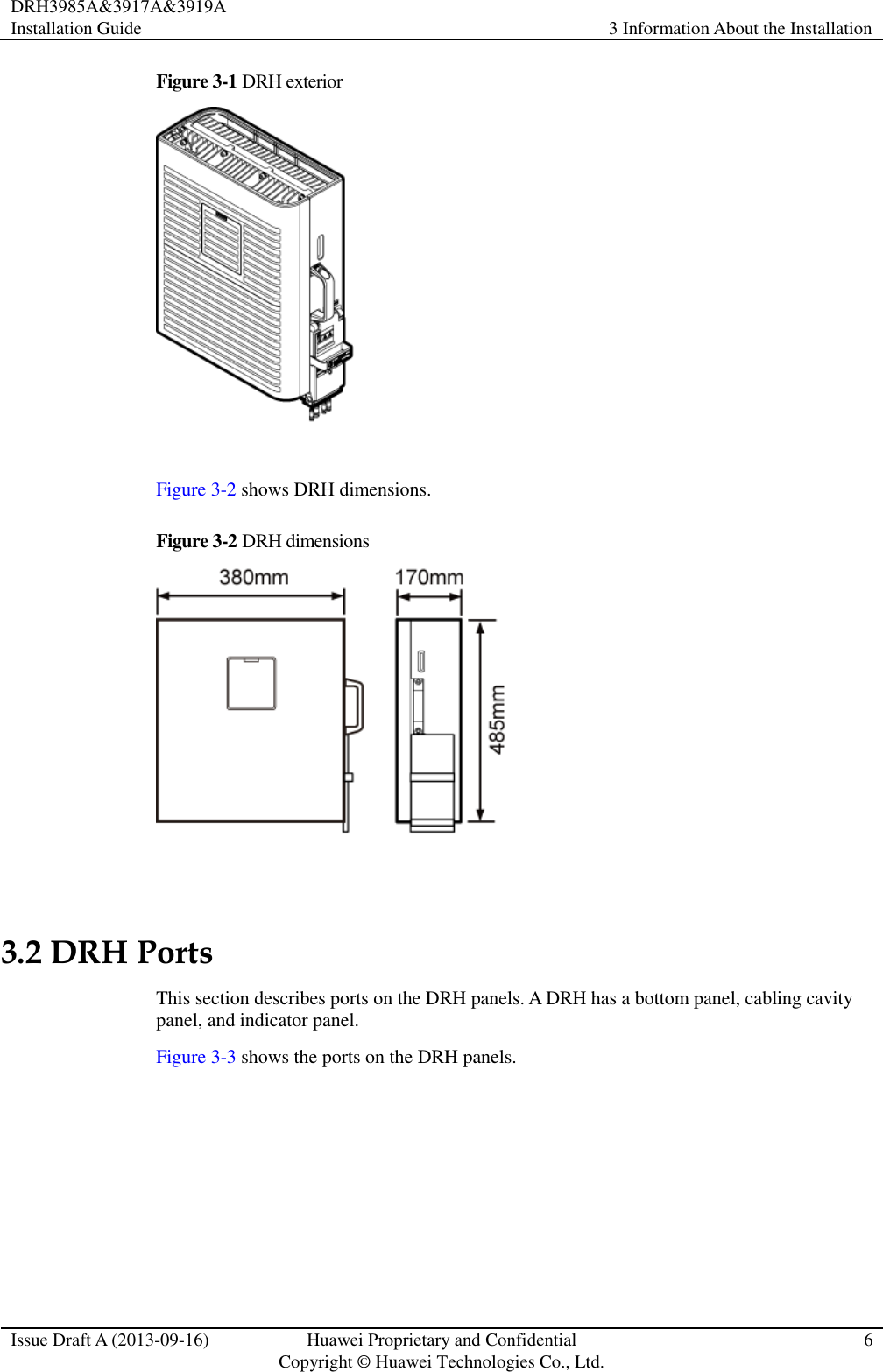
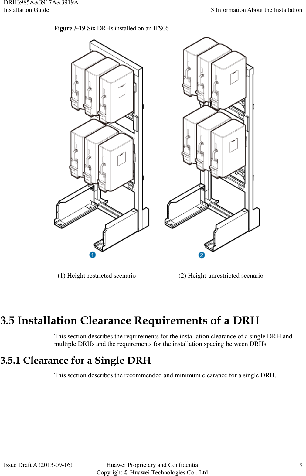
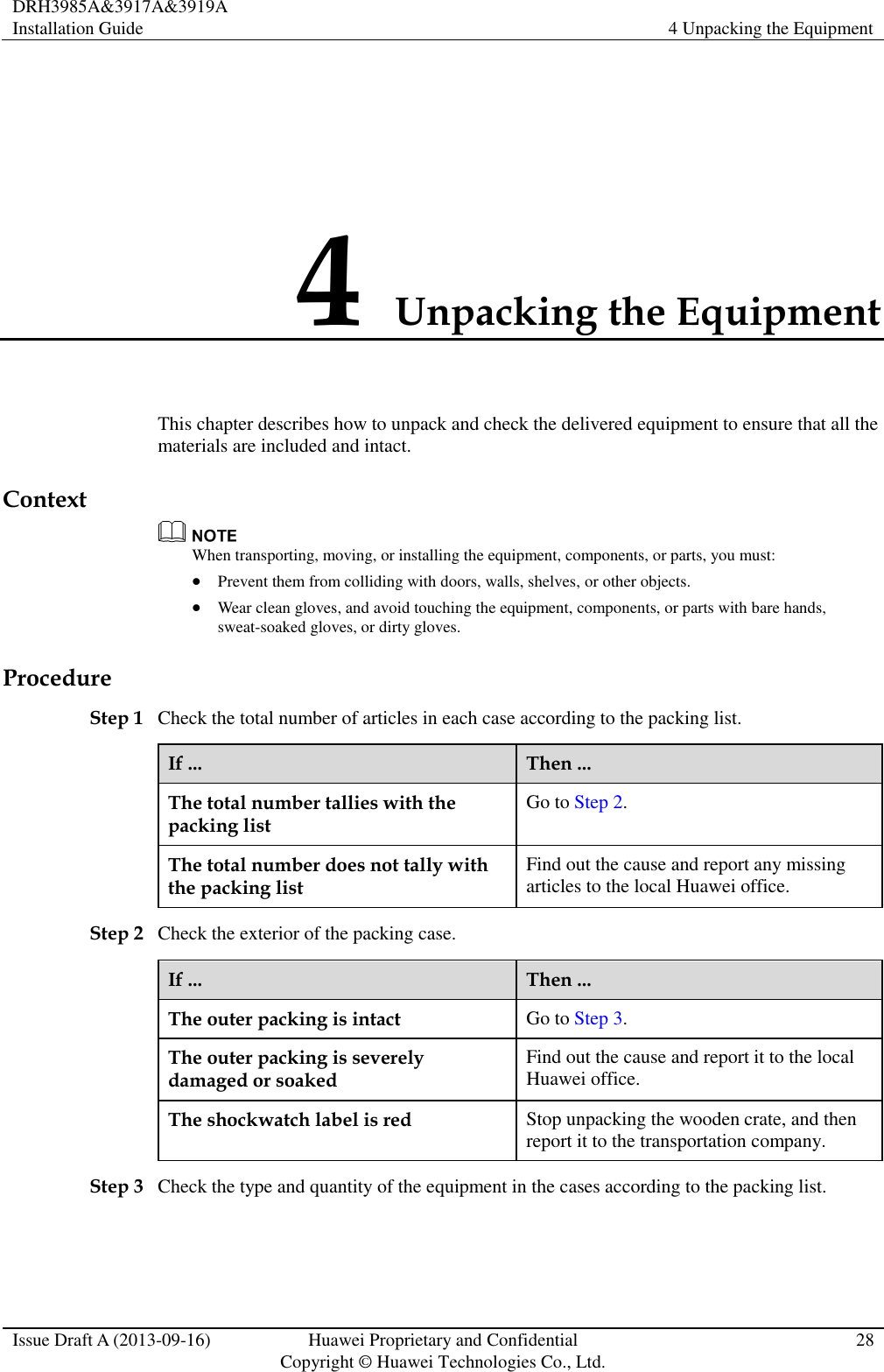
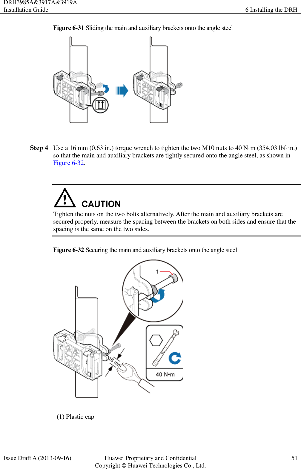
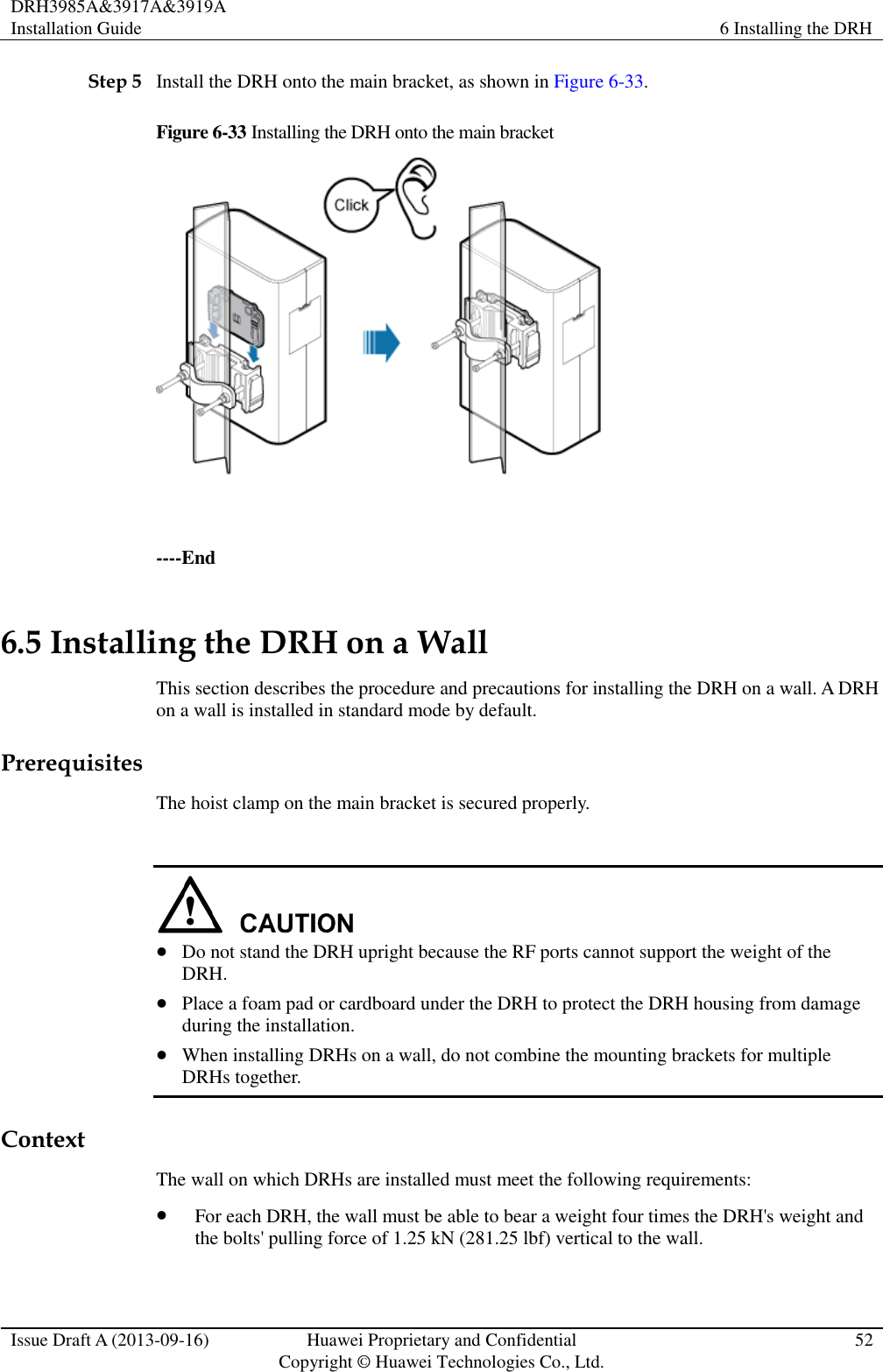
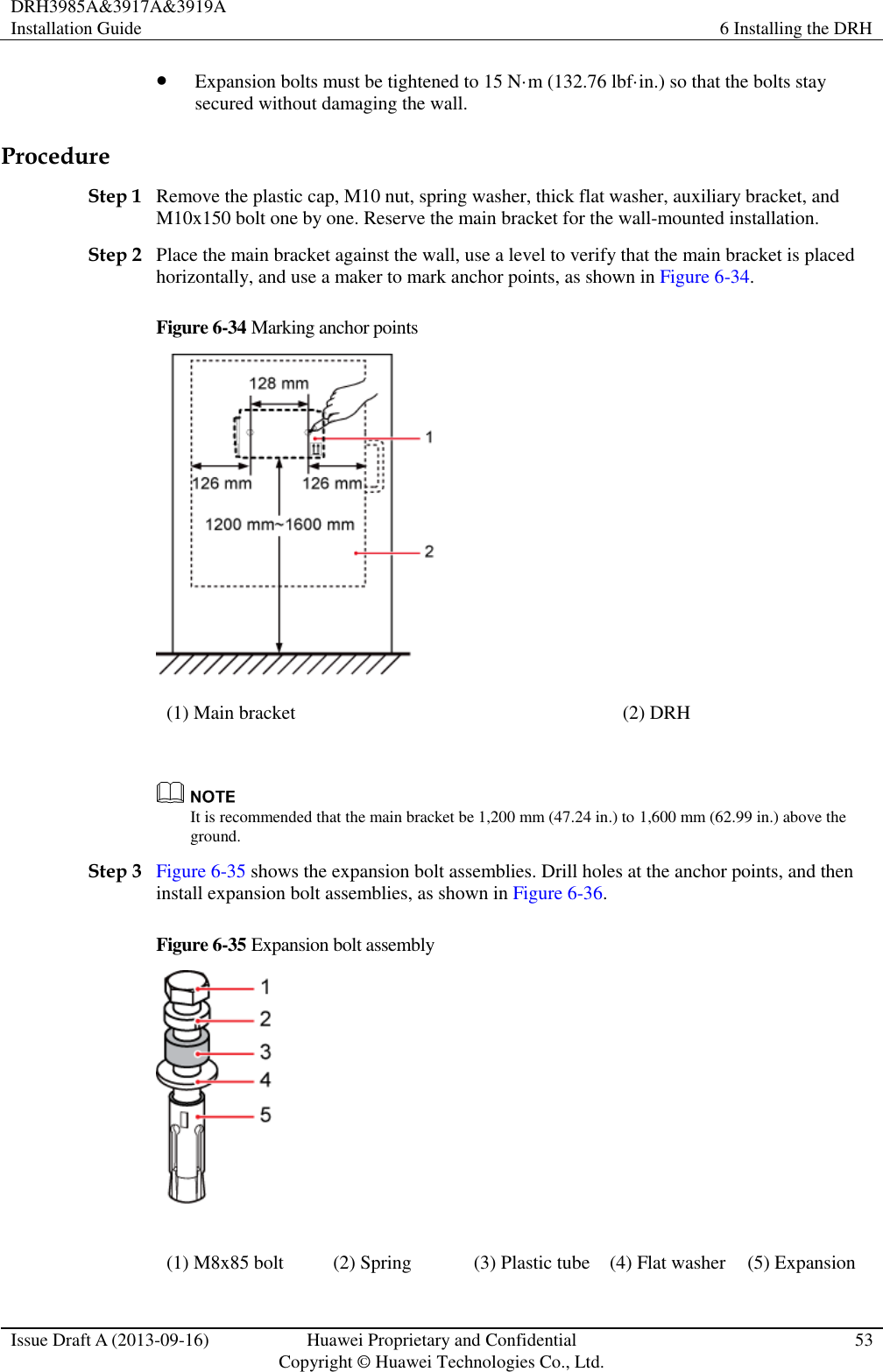
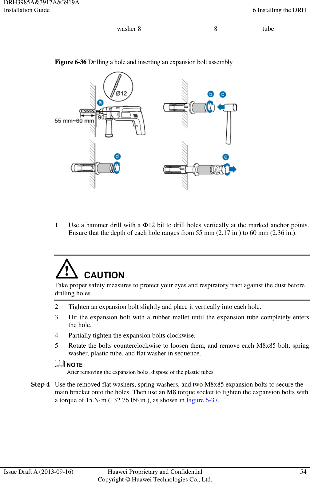
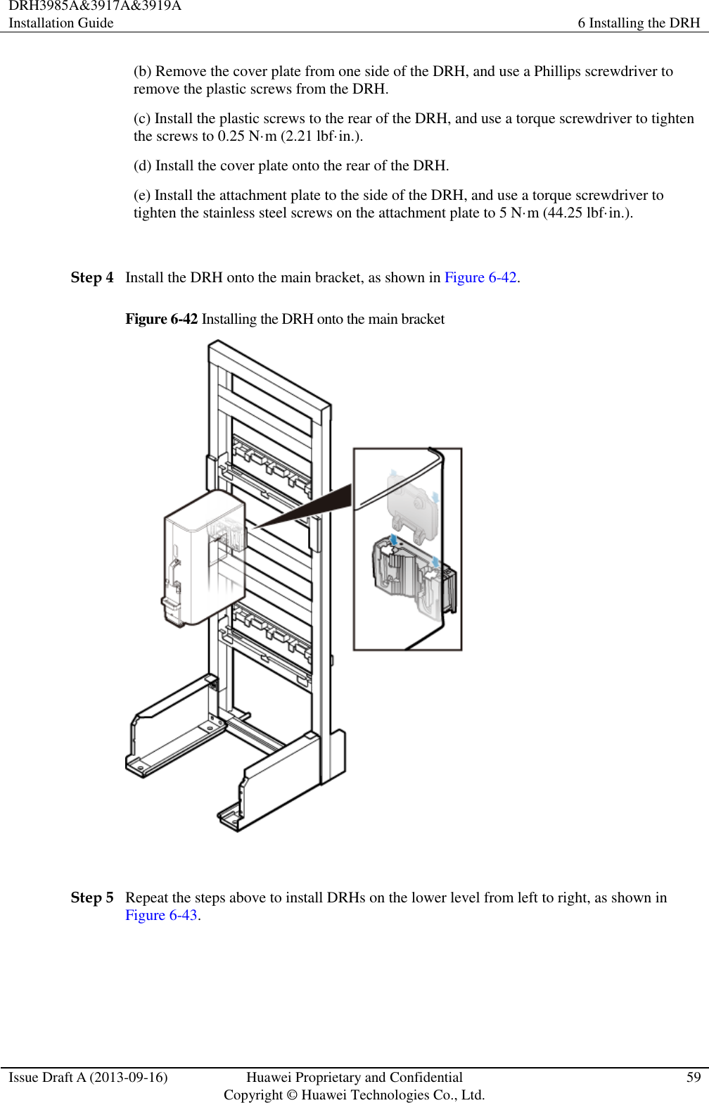
![DRH3985A&3917A&3919A Installation Guide About This Document Issue Draft A (2013-09-16) Huawei Proprietary and Confidential Copyright © Huawei Technologies Co., Ltd.. iv General Conventions Convention Description Times New Roman Normal paragraphs are in Times New Roman. Boldface Names of files, directories, folders, and users are in boldface. For example, log in as user root. Italic Book titles are in italics. Courier New Terminal display is in Courier New. Command Conventions Convention Description Boldface The keywords of a command line are in boldface. Italic Command arguments are in italics. [ ] Items (keywords or arguments) in square brackets [ ] are optional. { x | y | ... } Alternative items are grouped in braces and separated by vertical bars. One is selected. [ x | y | ... ] Optional alternative items are grouped in square brackets and separated by vertical bars. One or none is selected. { x | y | ... } * Alternative items are grouped in braces and separated by vertical bars. A minimum of one or a maximum of all can be selected. GUI Conventions Convention Description Boldface Buttons, menus, parameters, tabs, windows, and dialog titles are in boldface. For example, click OK. > Multi-level menus are in boldface and separated by the ">" signs. For example, choose File > Create > Folder. Keyboard Operation Format Description Key Press the key. For example, press Enter and press Tab.](https://usermanual.wiki/Huawei-Technologies/DRH3985A.User-Manual-II/User-Guide-2162187-Page-5.png)
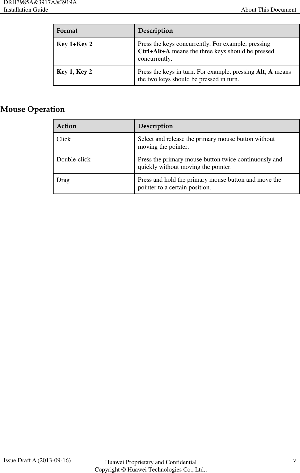
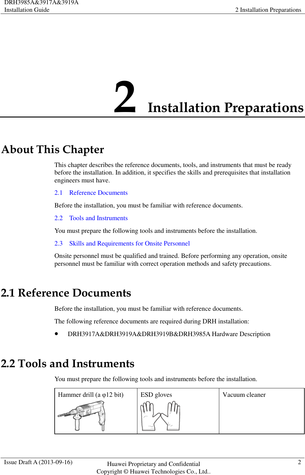
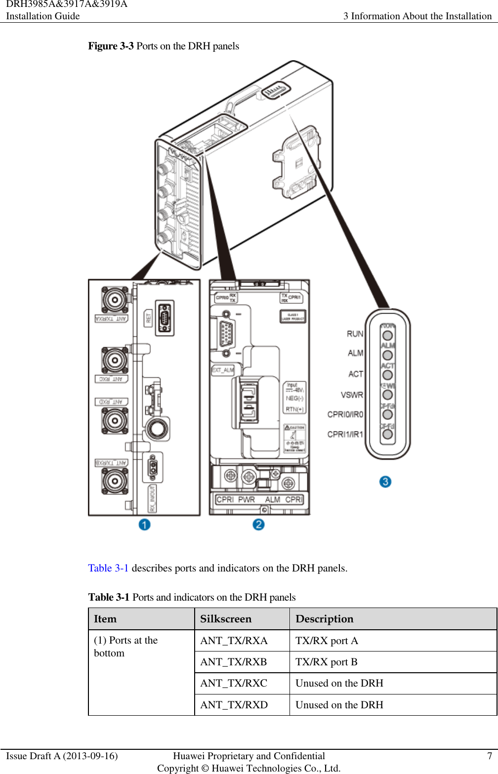
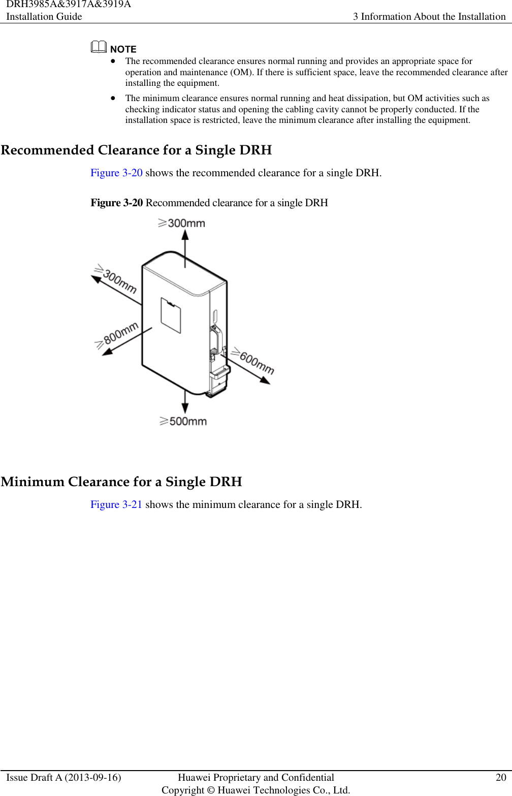
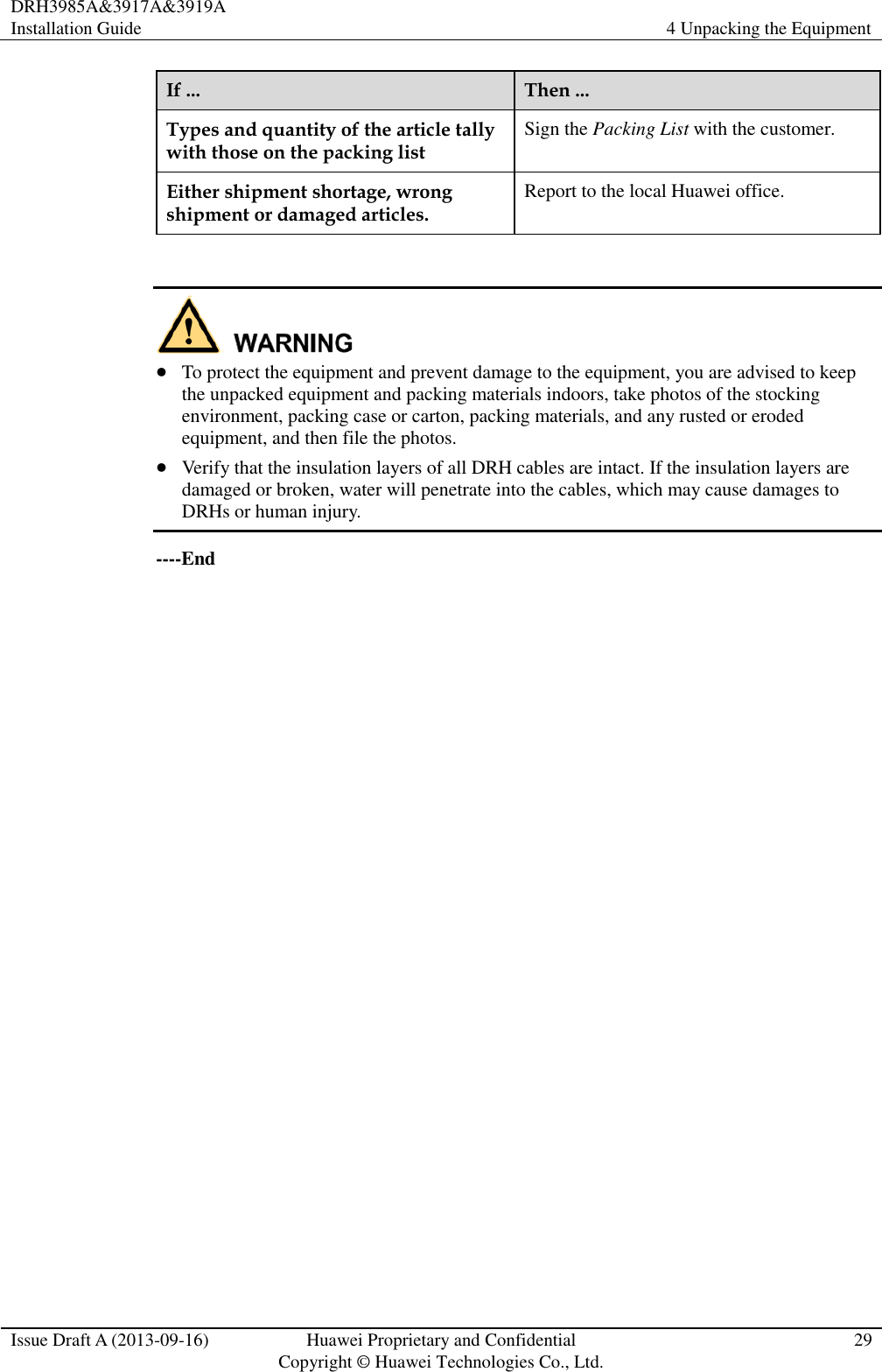
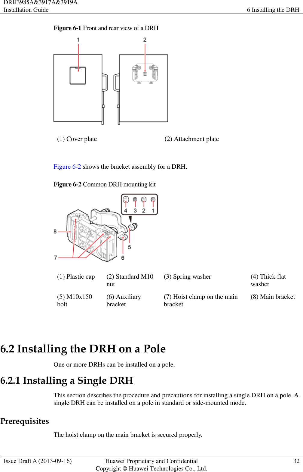
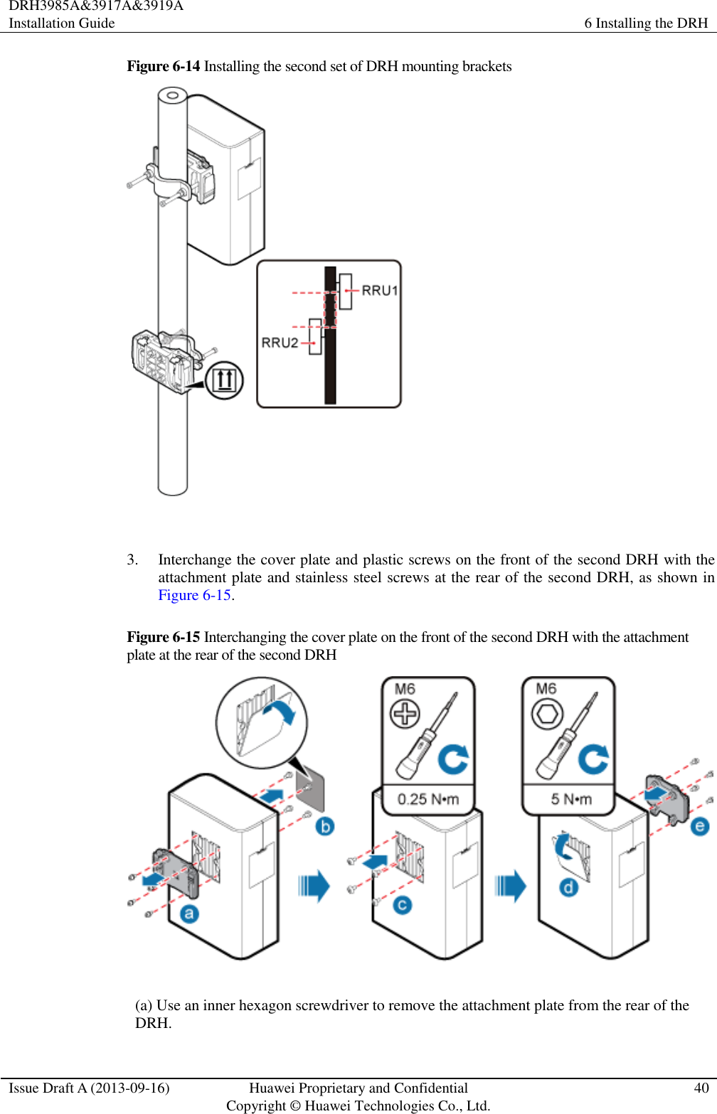
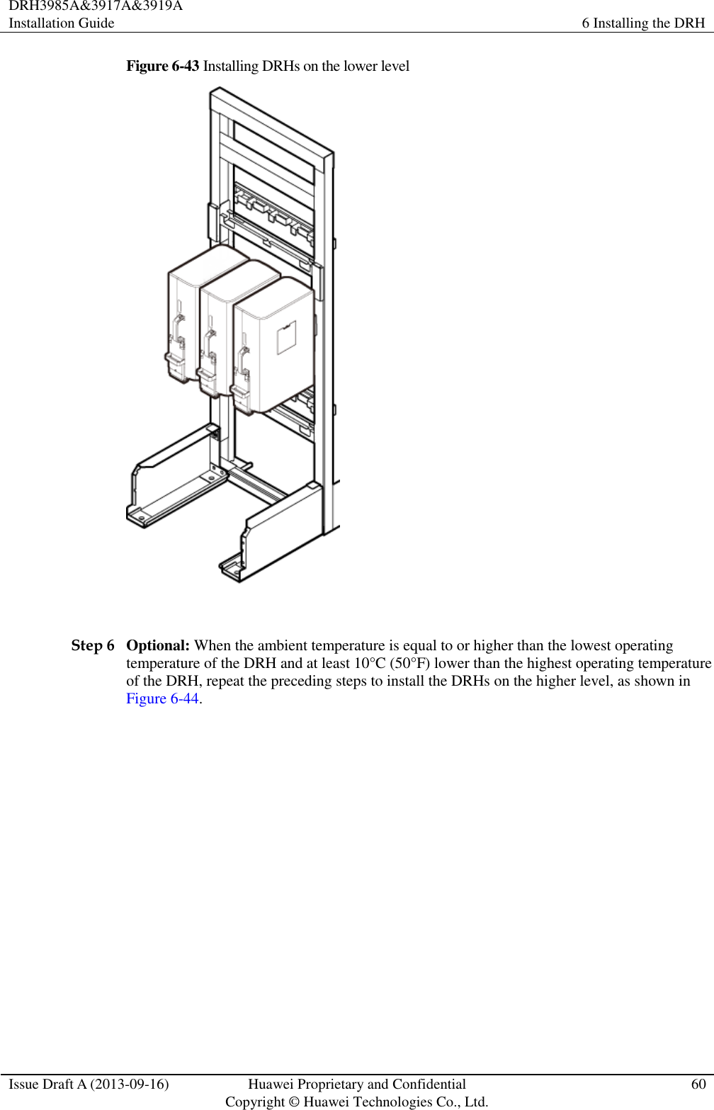
![DRH3985A&3917A&3919A Installation Guide 2 Installation Preparations Issue Draft A (2013-09-16) Huawei Proprietary and Confidential Copyright © Huawei Technologies Co., Ltd.. 3 Heat gun Phillips screwdriver (M3 to M6) Flat-head screwdriver (M3 to M6) Rubber mallet COAX crimping tool Wire stripper Utility knife Cable cutter Adjustable wrench (size ≥ 32 mm [1.26 in.]) Torque wrench Size: 16 mm (0.63 in.) and 32 mm (1.26 in.) Combination wrench Size: 16 mm (0.63 in.) and 32 mm (1.26 in.) Level Torque screwdriver 5 mm 5 mm (M3 to M6) (M3 to M6) Torque socket Multimeter Marker (diameter ≤ 10 mm [0.39 in.]) Measuring tape Inner hexagon wrench Hydraulic pliers](https://usermanual.wiki/Huawei-Technologies/DRH3985A.User-Manual-II/User-Guide-2162187-Page-11.png)
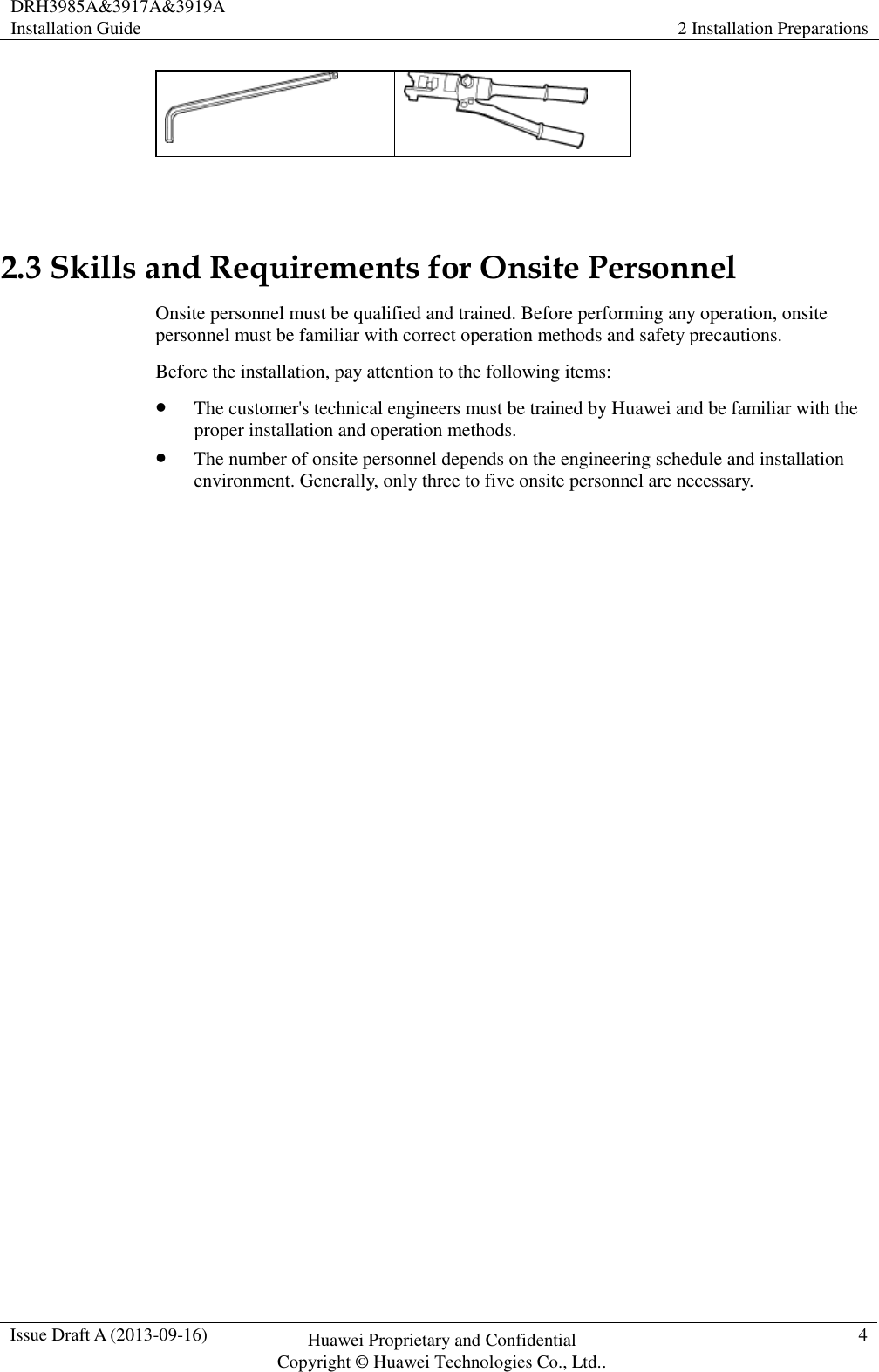
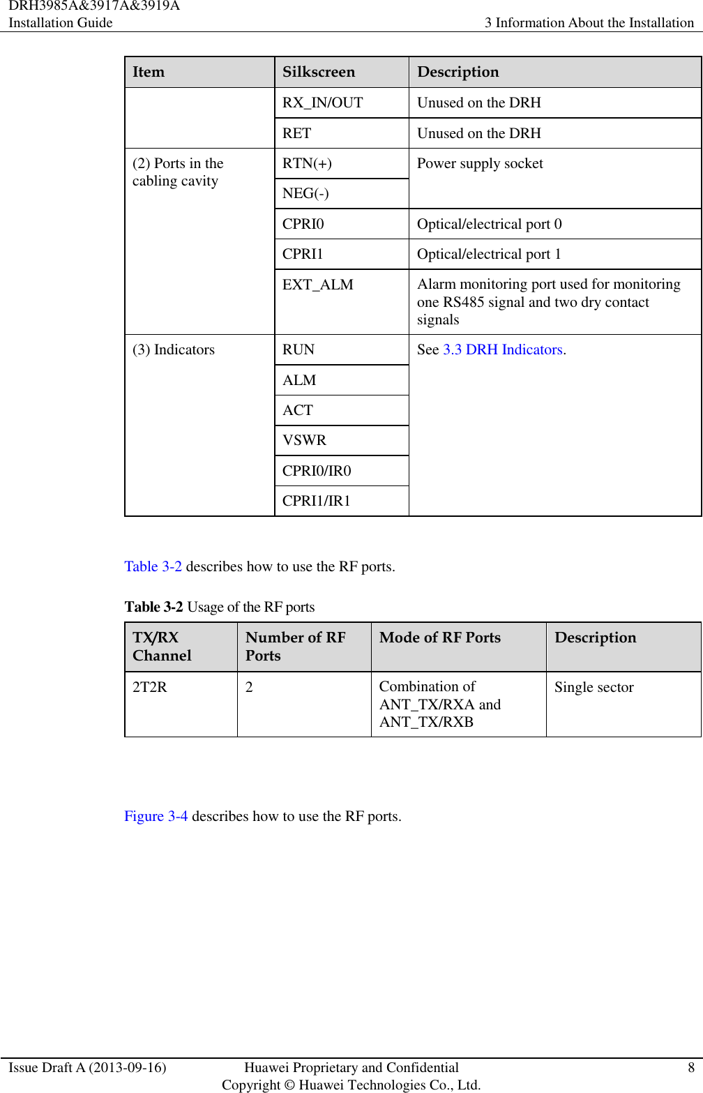

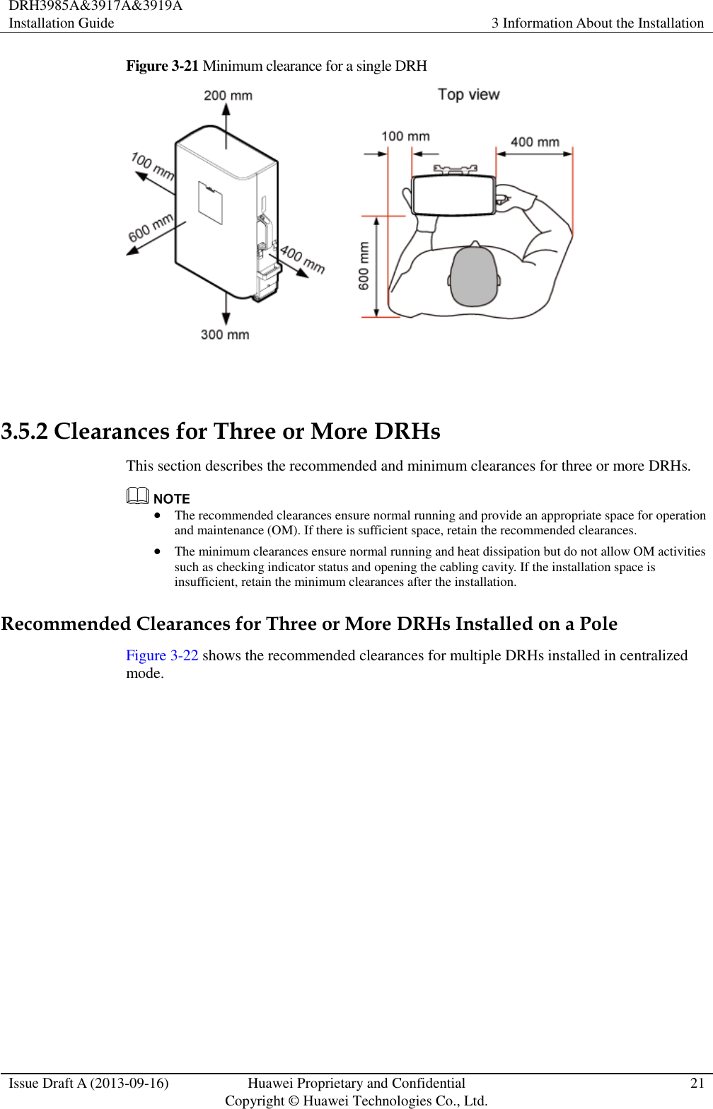
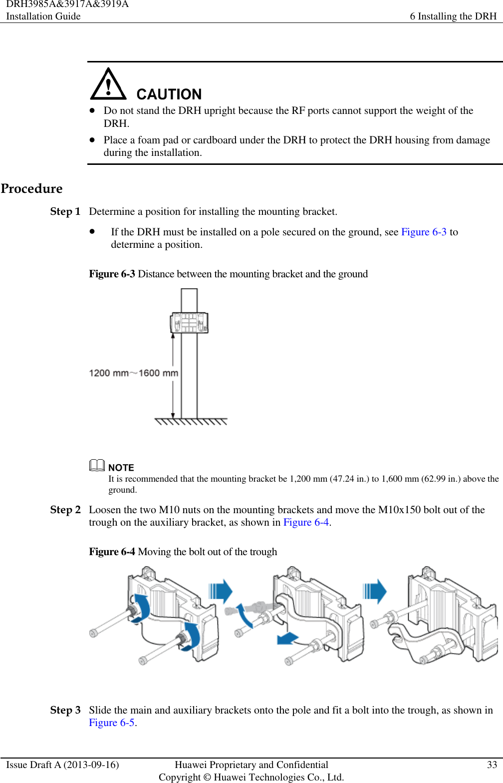
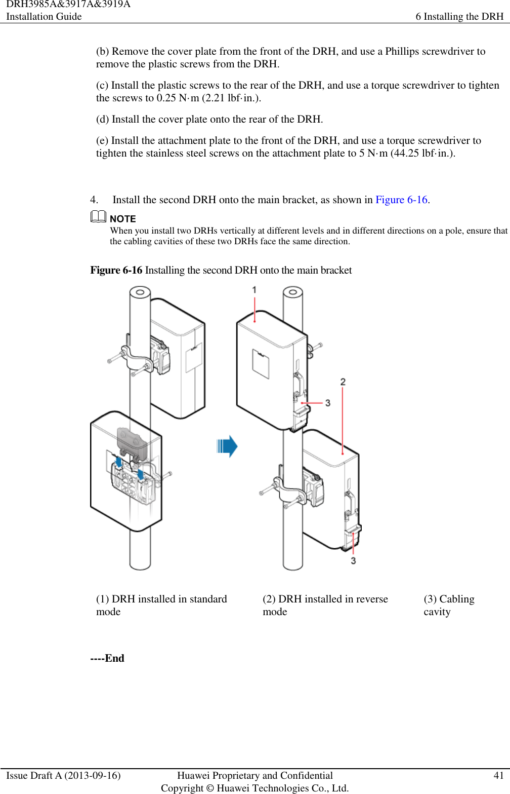
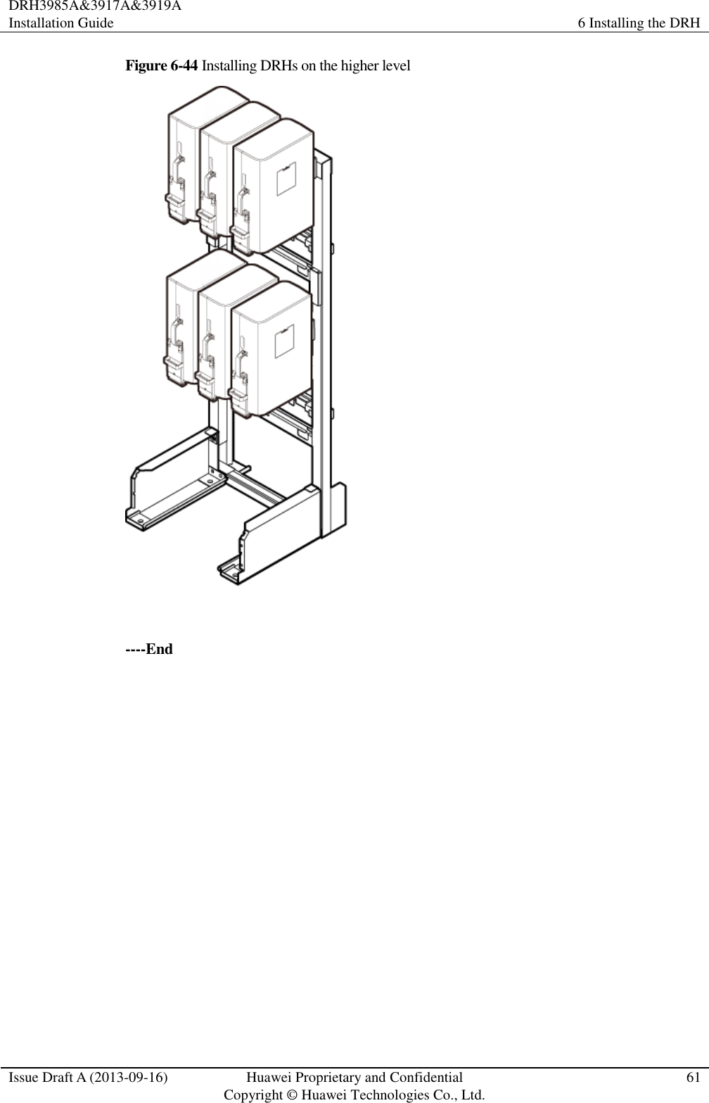
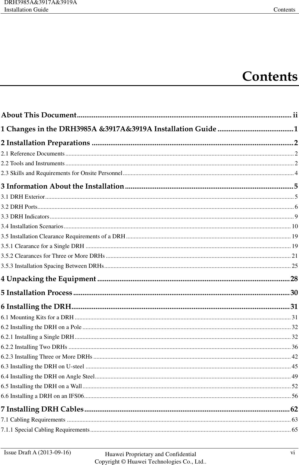
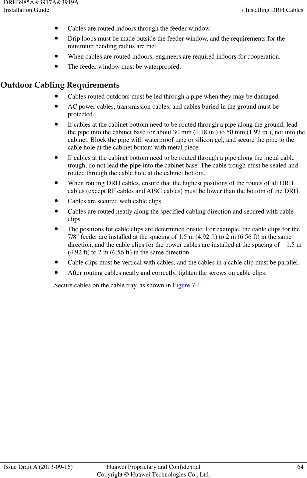
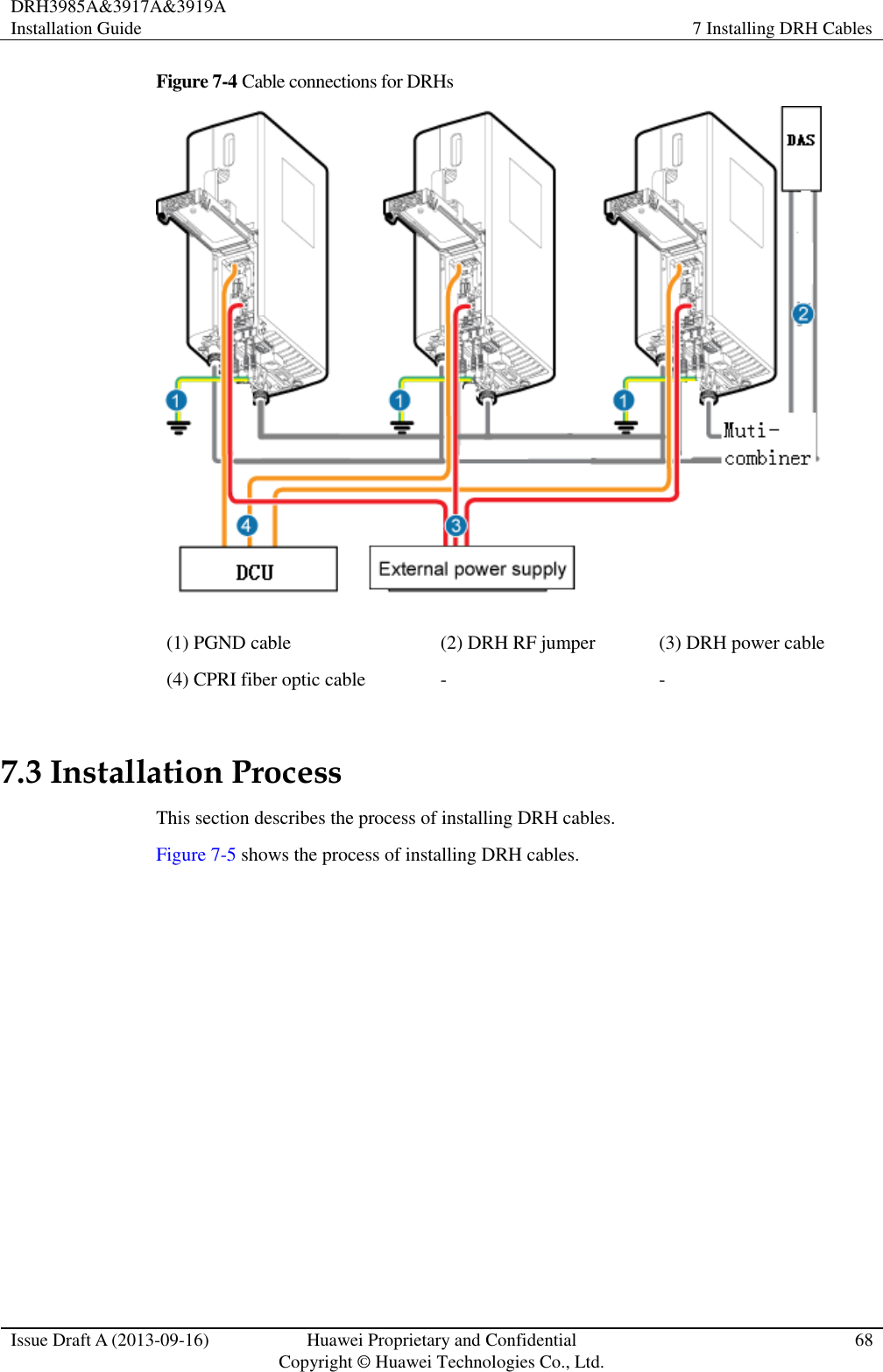
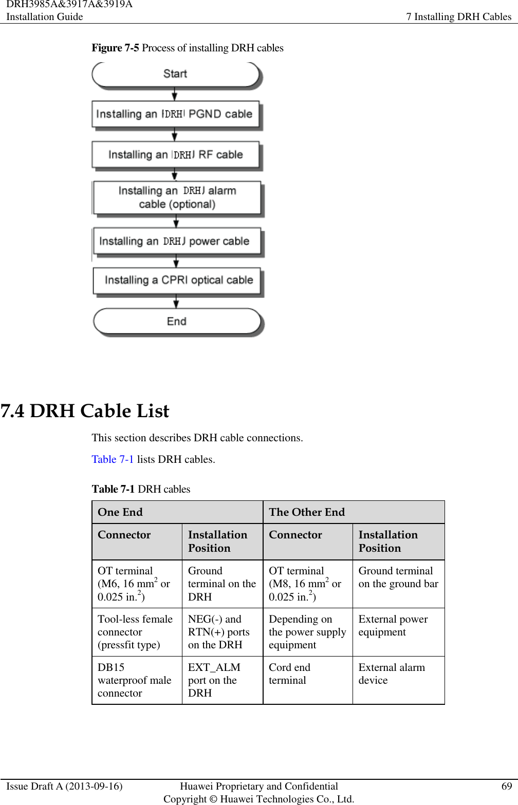
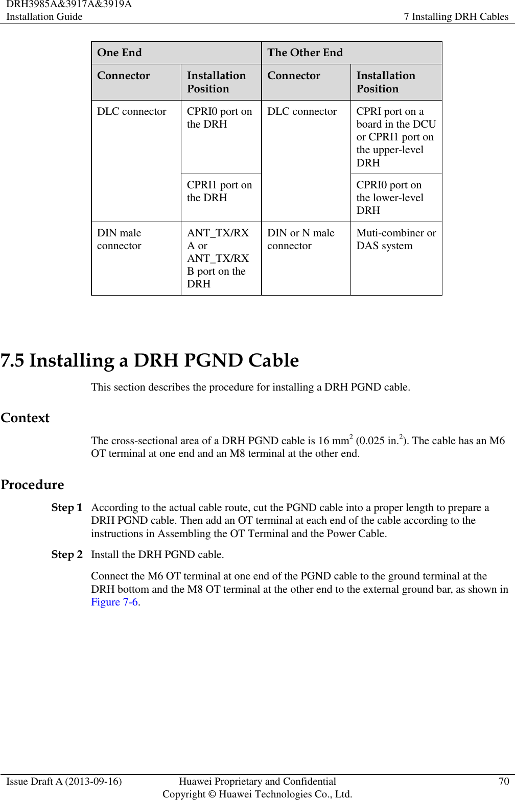
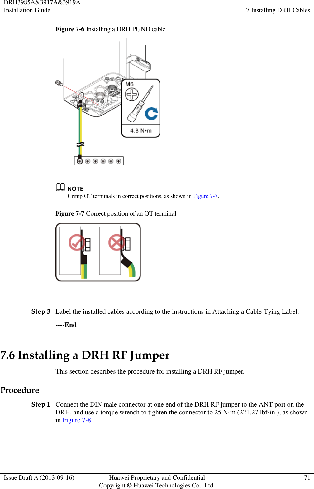
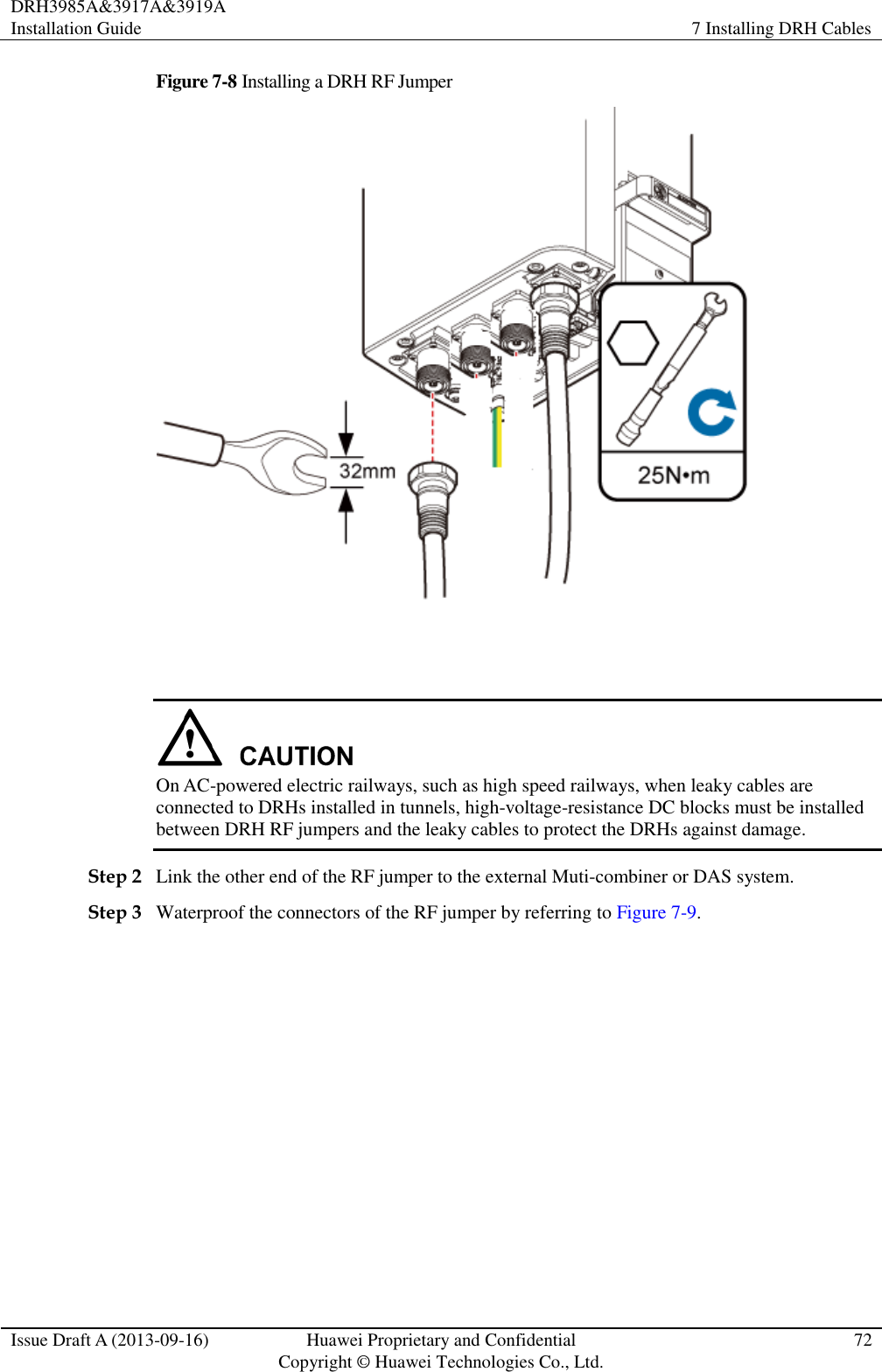
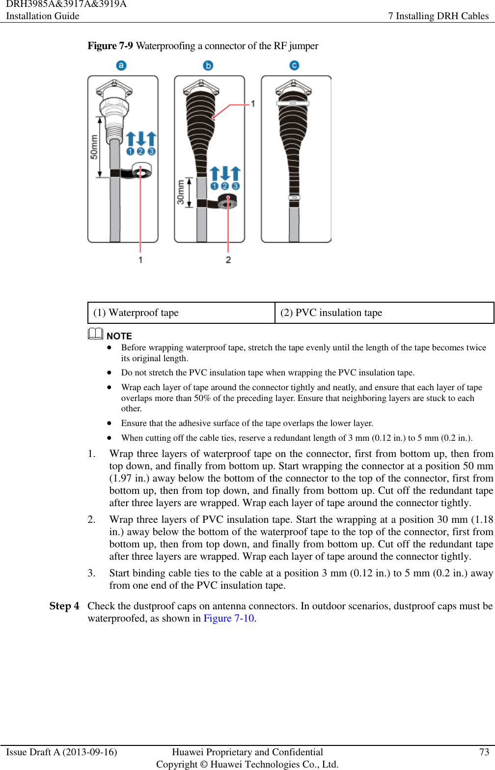
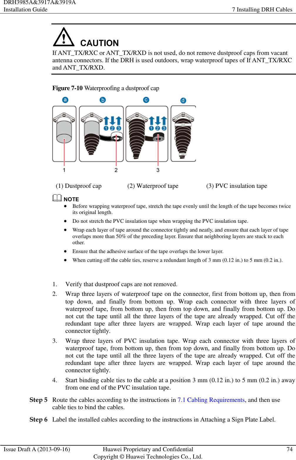
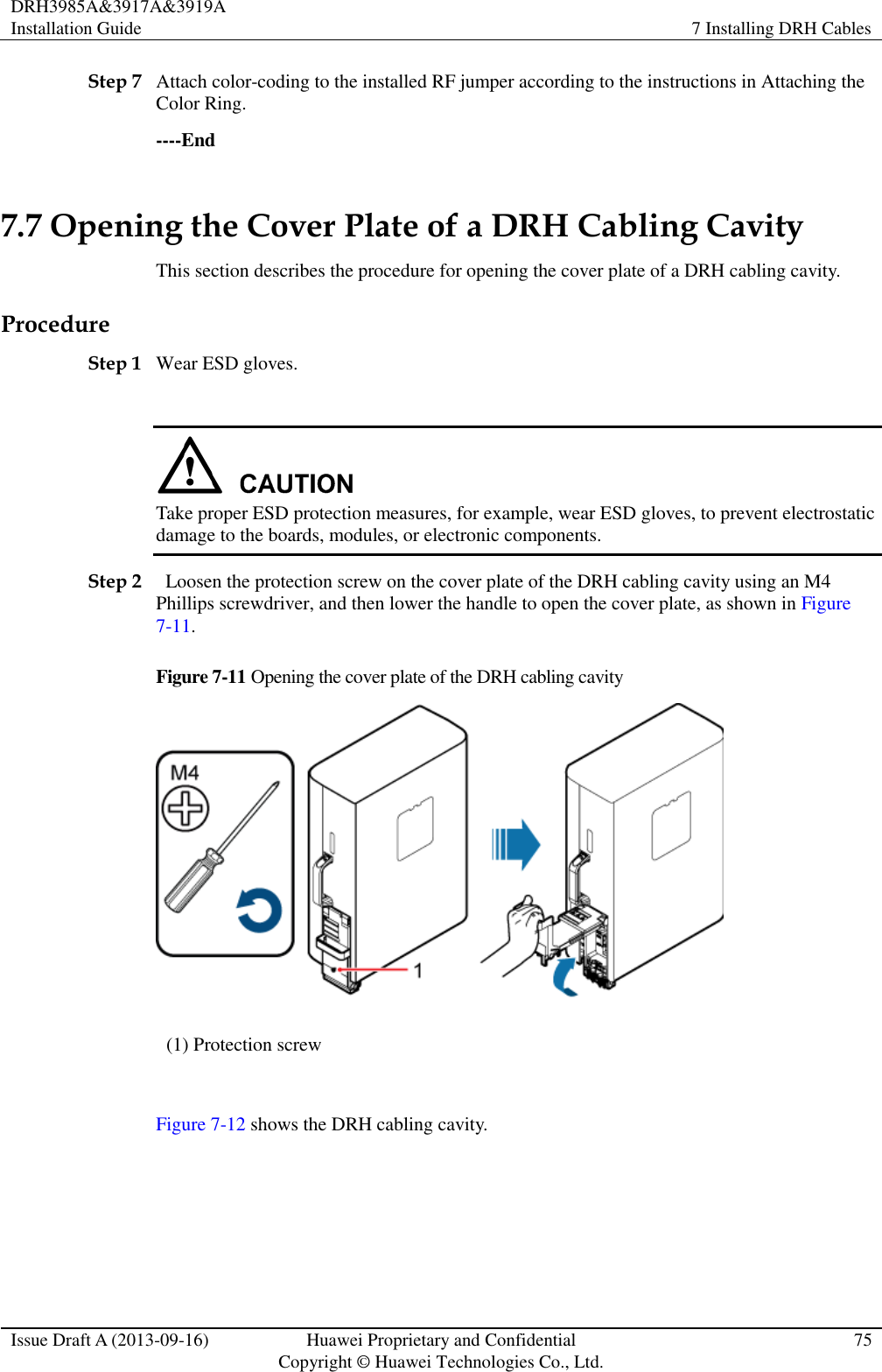
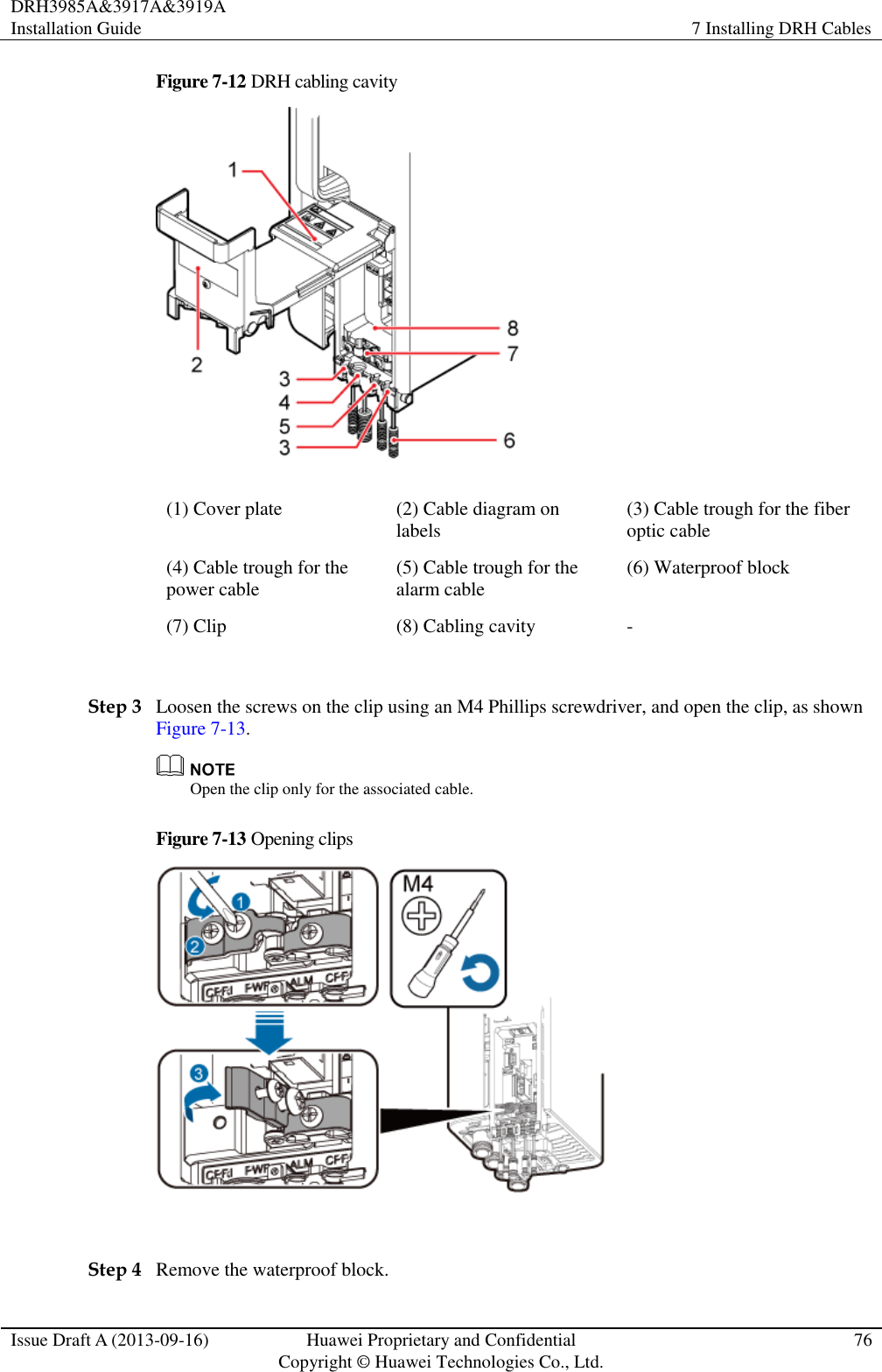
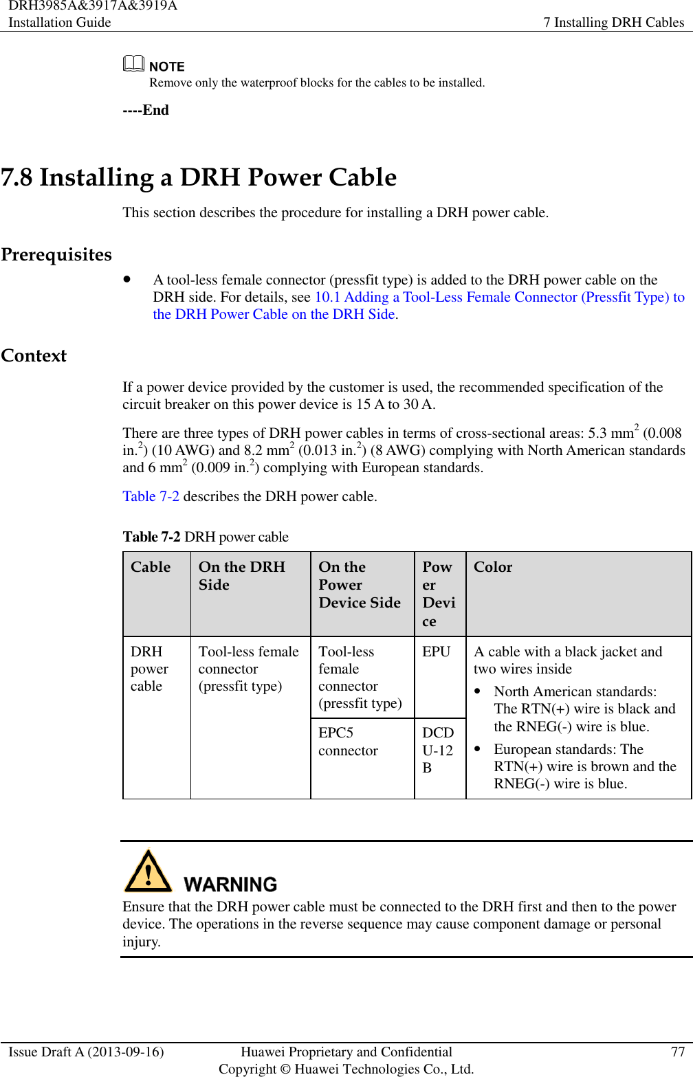
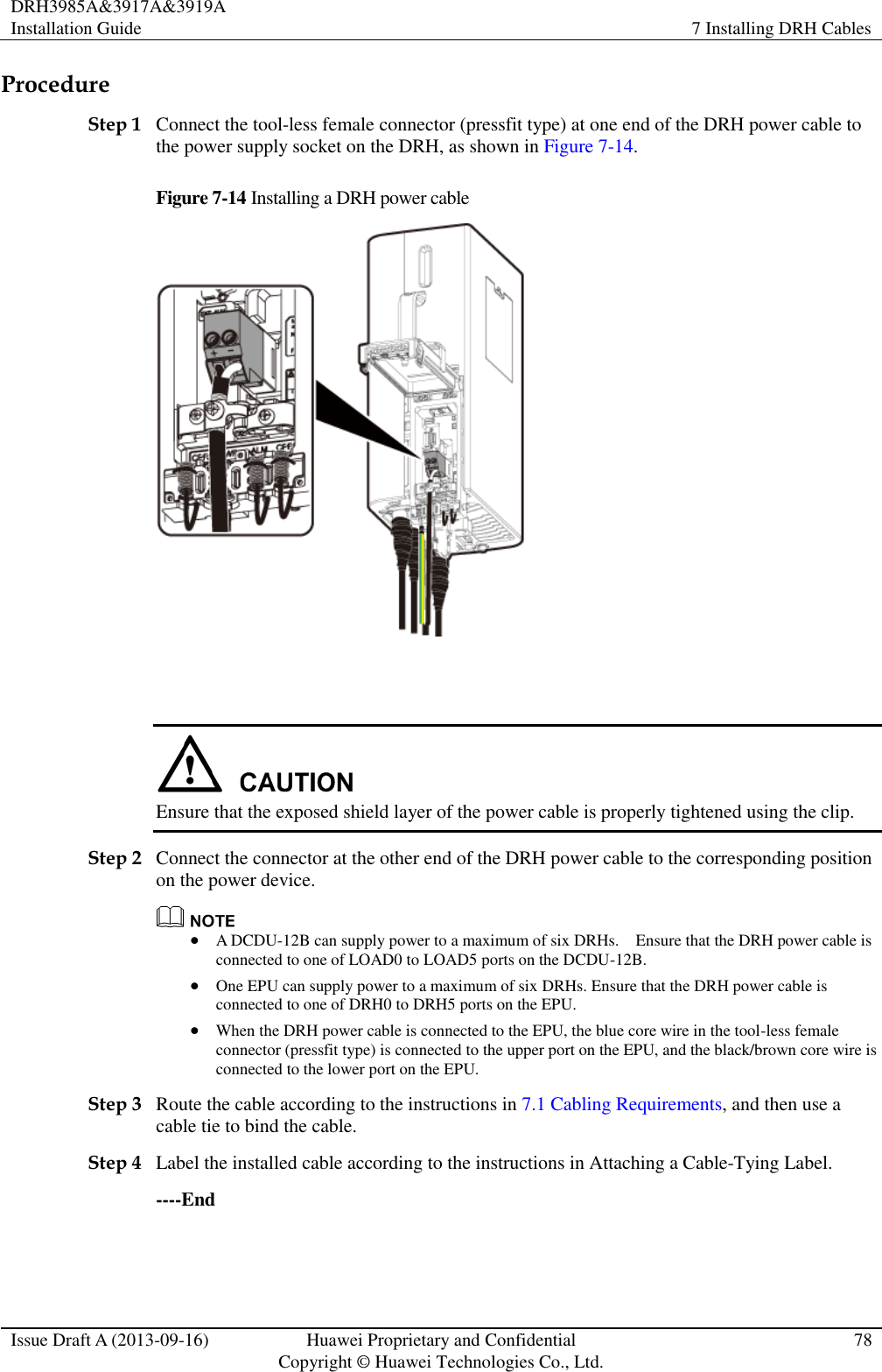
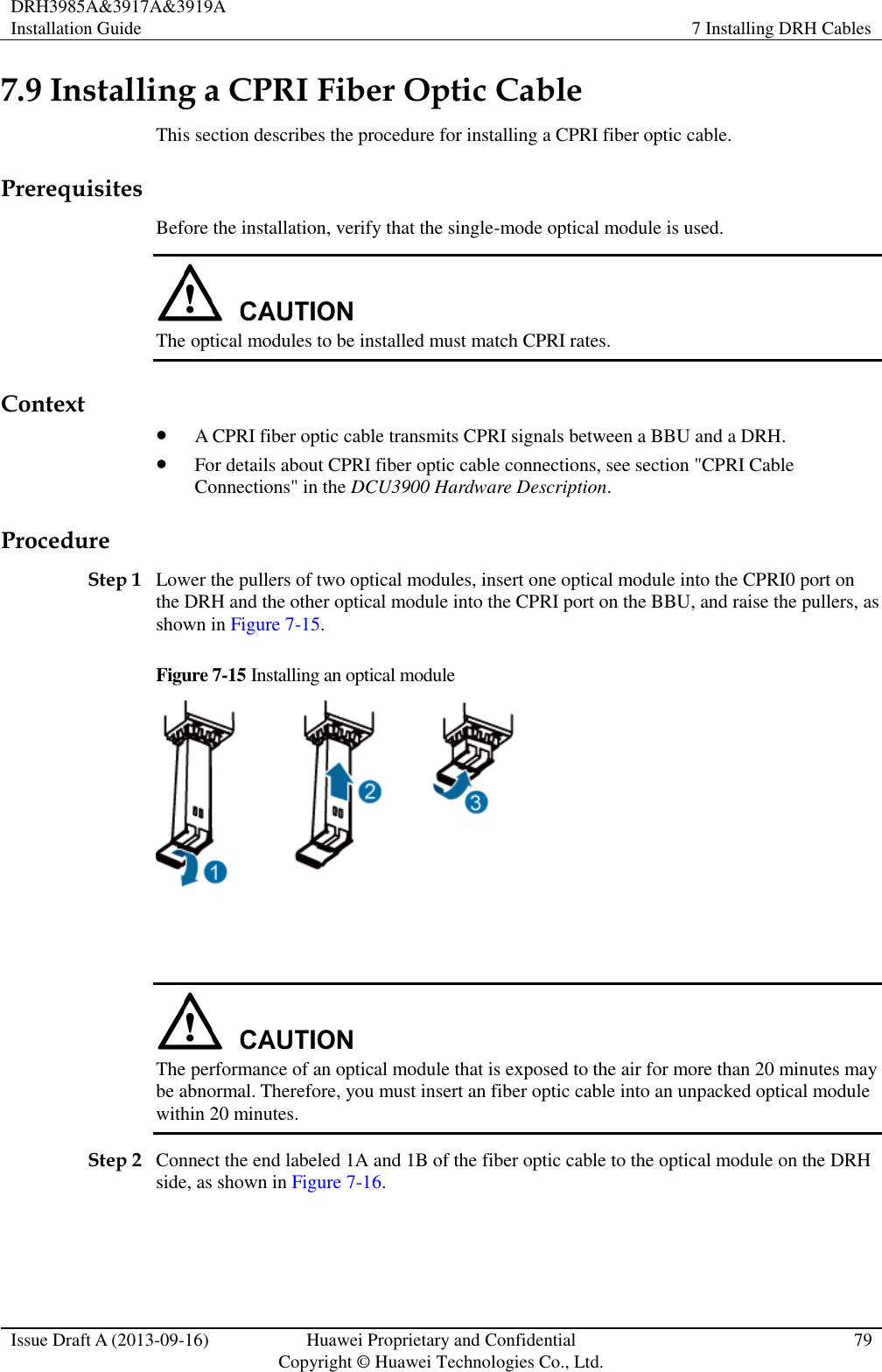
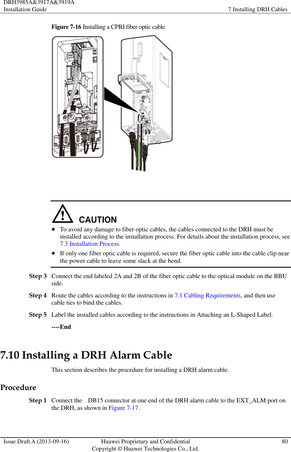
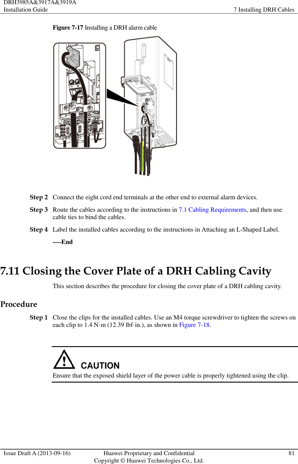
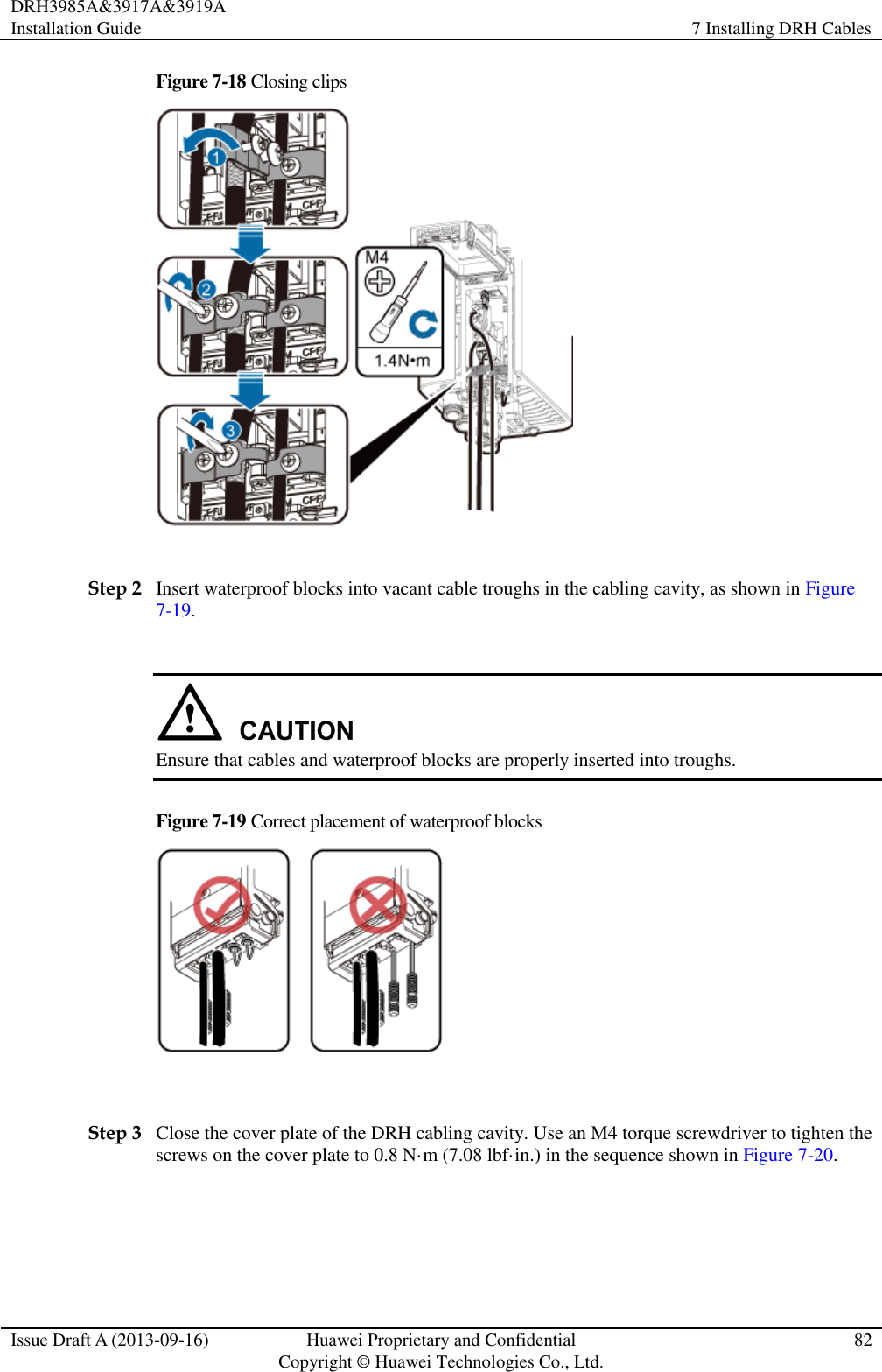
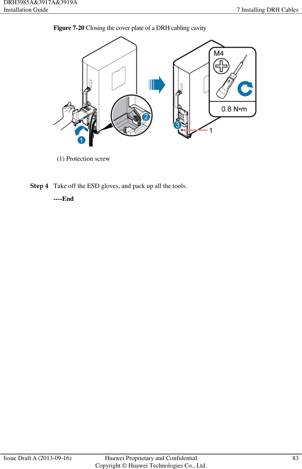
![DRH3985A&3917A&3919A Installation Guide 7 Installing DRH Cables Issue Draft A (2013-09-16) Huawei Proprietary and Confidential Copyright © Huawei Technologies Co., Ltd. 63 This section describes the procedure for closing the cover plate of a DRH cabling cavity. 7.1 Cabling Requirements Cables must be routed according to the specified cabling requirements to prevent signal interference. If a cable listed below is not required, skip the routing requirements of the cable. General Cabling Requirements Requirements for Bending Radius The bending radius of the 7/8'' feeder must be more than 250 mm (9.84 in.), and the bending radius of the 5/4'' feeder must be more than 380 mm (14.96 in.). The bending radius of the 1/4'' jumper must be more than 35 mm (1.38 in.). The bending radius of the super-flexible 1/2'' jumper must be more than 50 mm (1.97 in.), and the bending radius of the ordinary 1/2'' jumper must be more than 127 mm (5 in.). The bending radius of the power cable or PGND cable must be at least three times the diameter of the cable. The bending radius of a fiber optic cable is at least 20 times the diameter of the fiber optic cable, and the minimum bending radius of the breakout cable at each end of the fiber optic cable is 30 mm (1.18 in.). The bending radius of the signal cable must be at least five times the diameter of the cable. Requirements for Cable Binding The same types of cable must be bound together. Different types of cable must be separately routed with the minimum spacing of 30 mm (1.18 in.) and cannot be entangled. The cables must be bound tightly and neatly. The sheaths of the cables must not be damaged. Cable ties are installed in the same direction, and those at the same horizontal line must be in a straight line. The excess of indoor cable ties is trimmed off, and the excess of outdoor cable ties allows about 5 mm (0.2 in.), without remaining rough edges. Labels or nameplates must be attached to both ends, joints, or turns of cables after they are installed. Security Requirements Cables should be placed away from sharp objects or wall burrs. If these positions are inevitable, protect the cables with protection pipes. Cables must be routed away from heat sources, or heat-insulation materials are added between cables and heat sources. Sufficient slack (recommended for about 0.1 m [0.33 ft]) is provided in cables at turns or the position close to a device, facilitating cable and device maintenance. Indoor Cabling Requirements](https://usermanual.wiki/Huawei-Technologies/DRH3985A.User-Manual-II/User-Guide-2162187-Page-71.png)
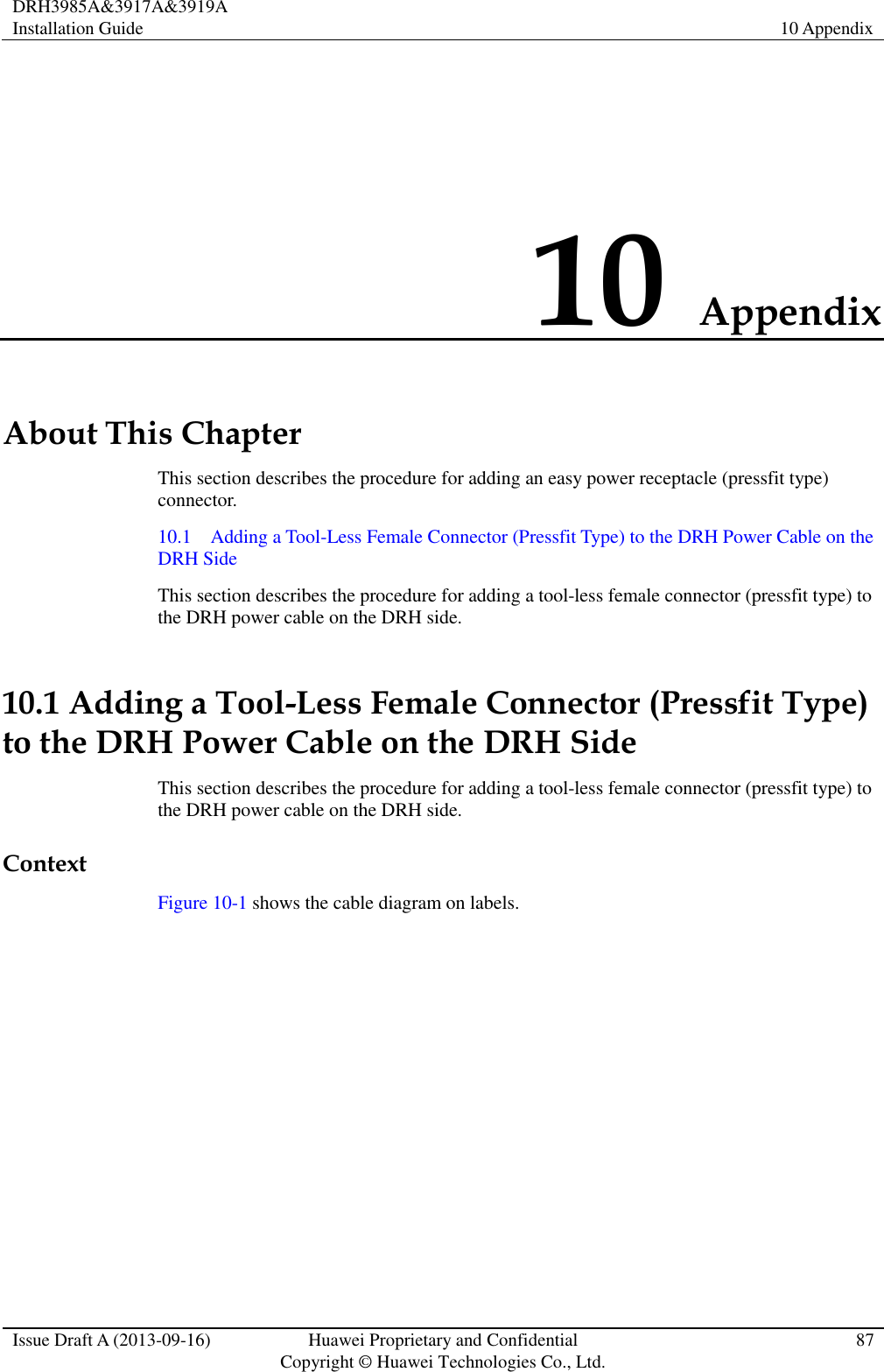
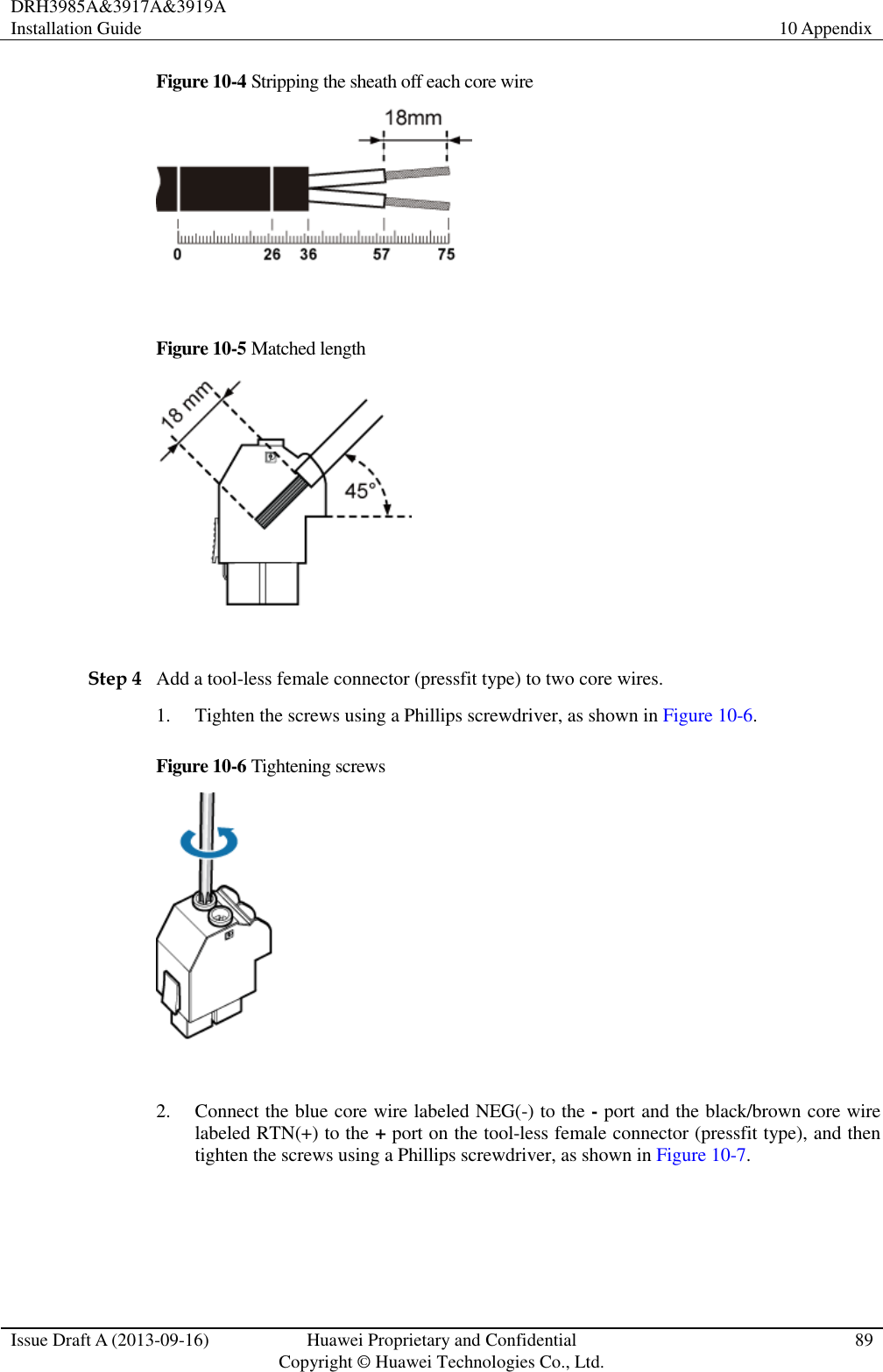
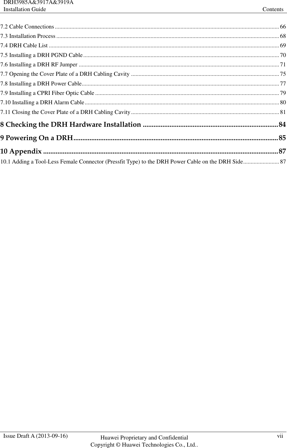
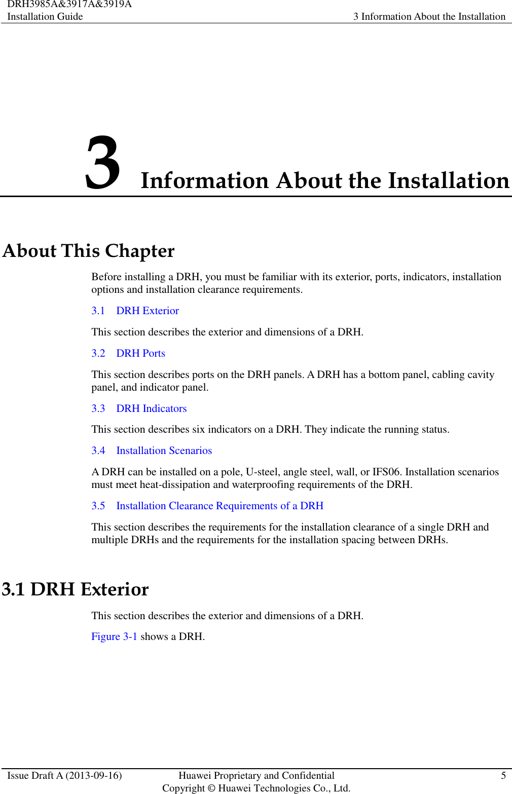
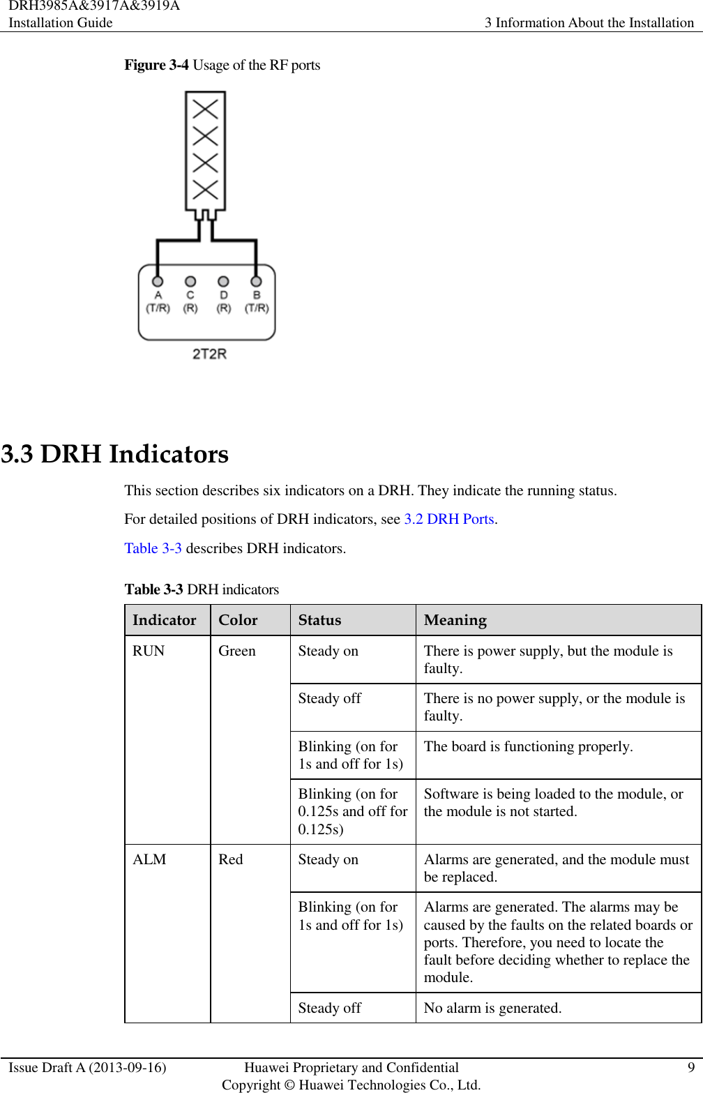
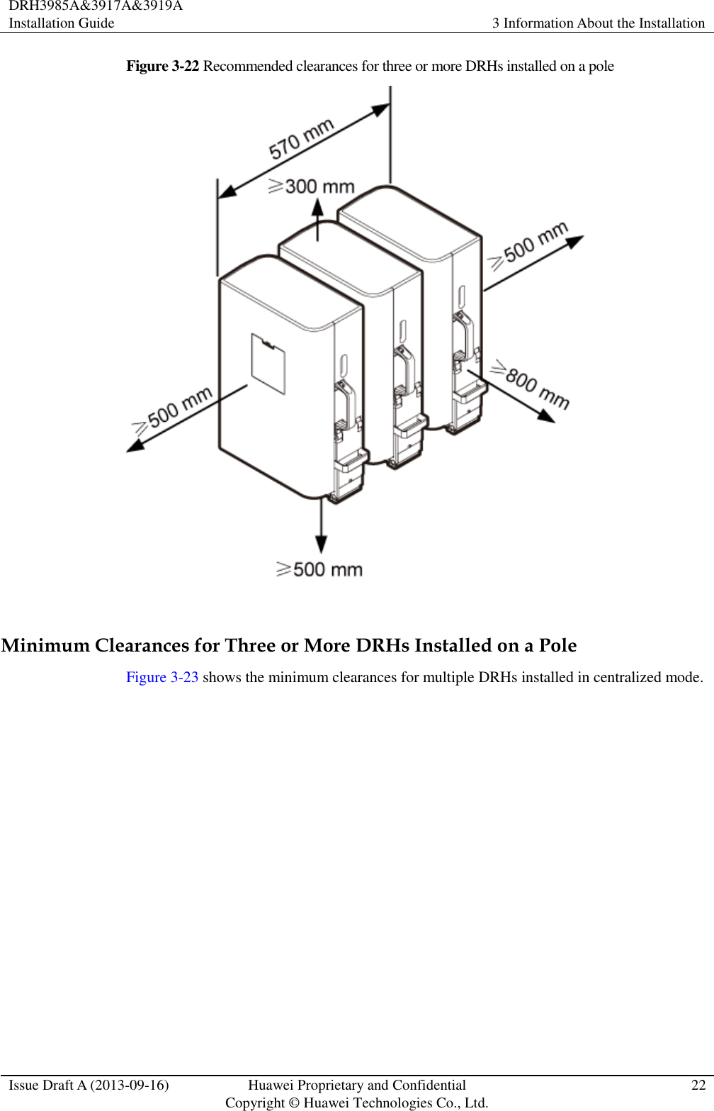
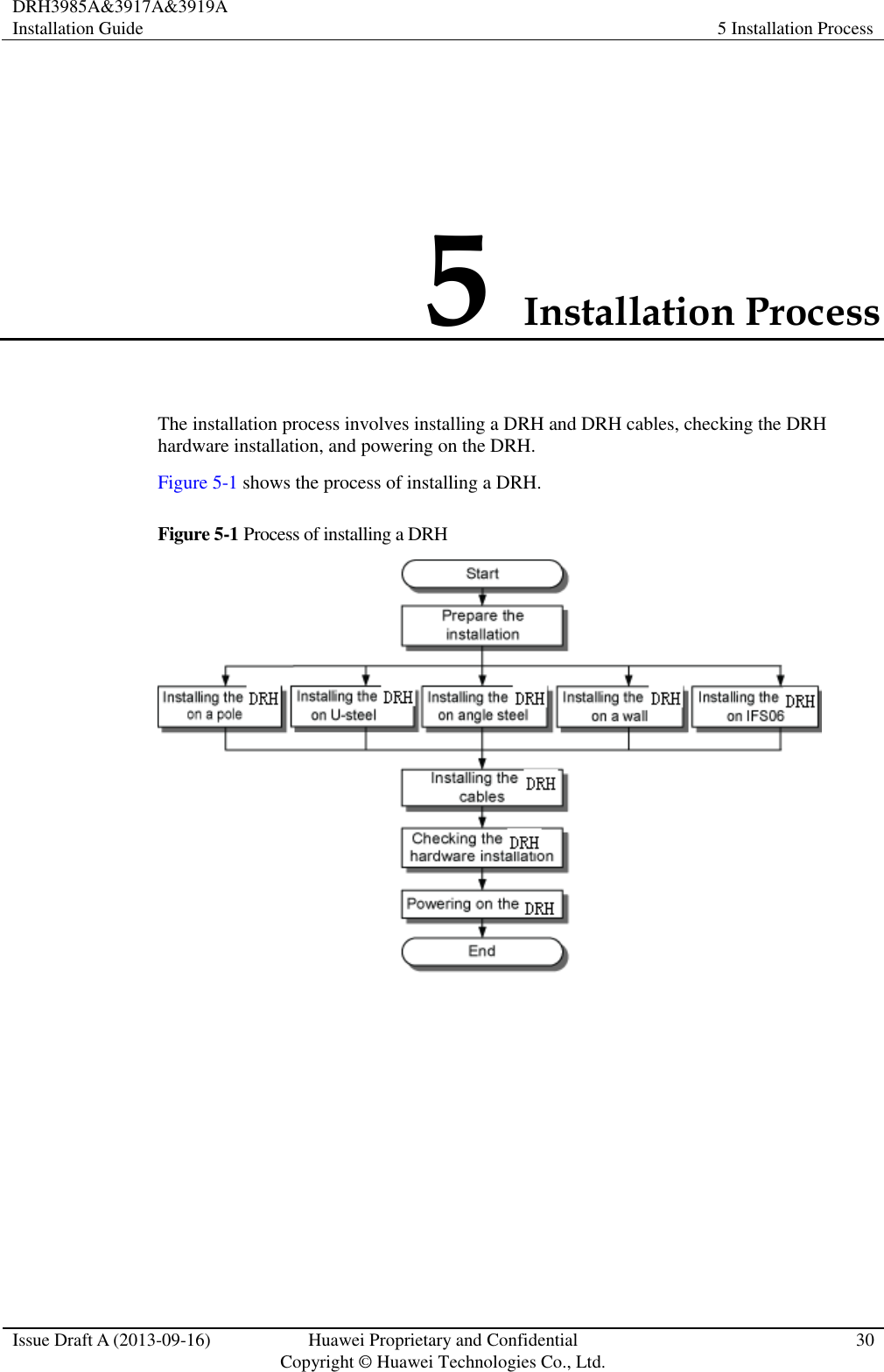
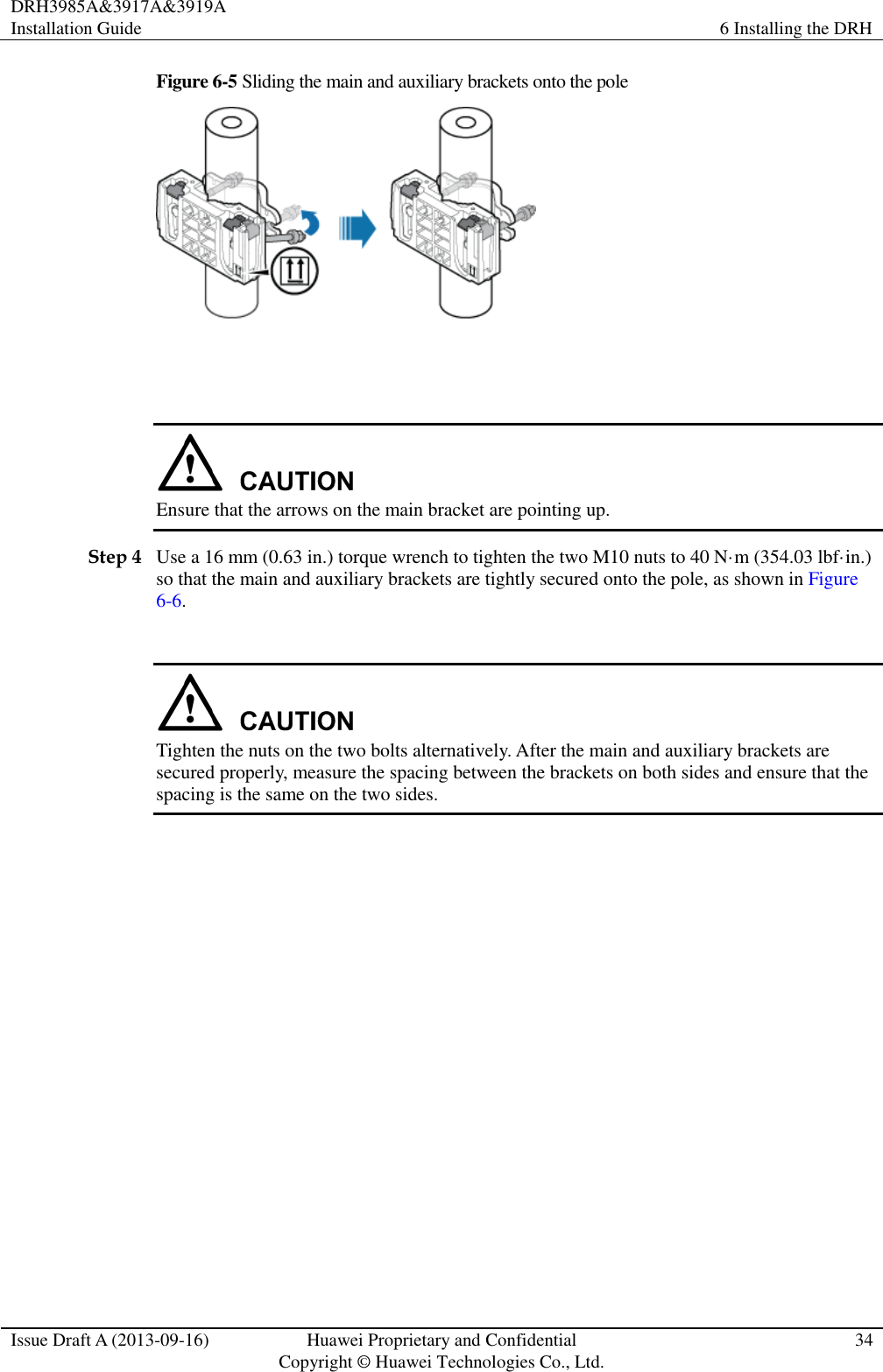
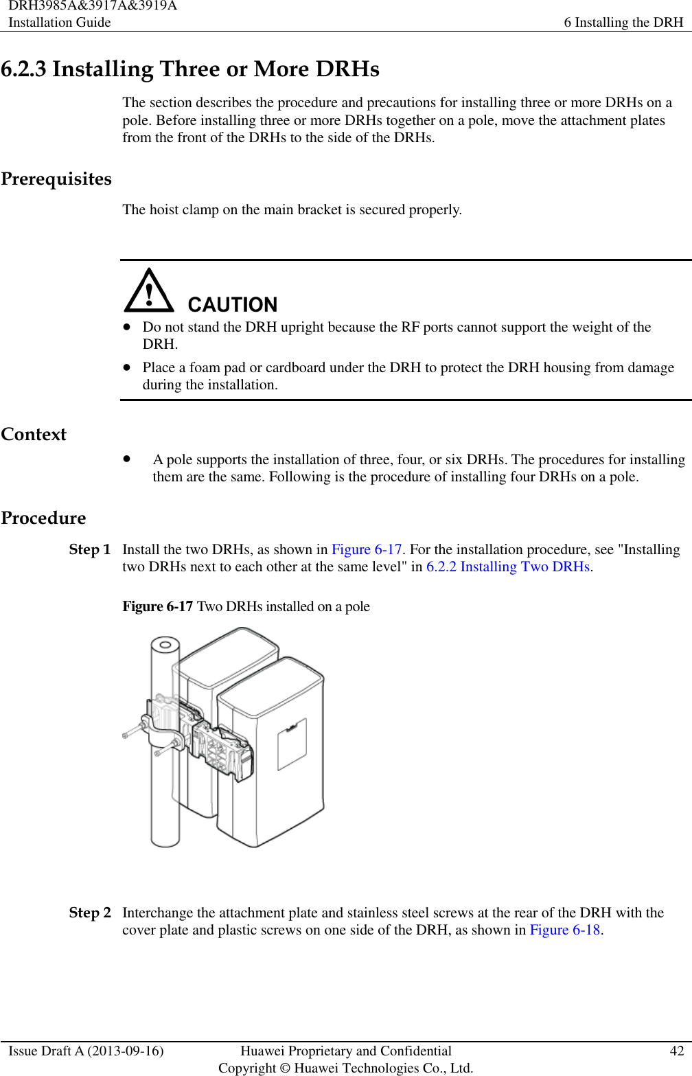
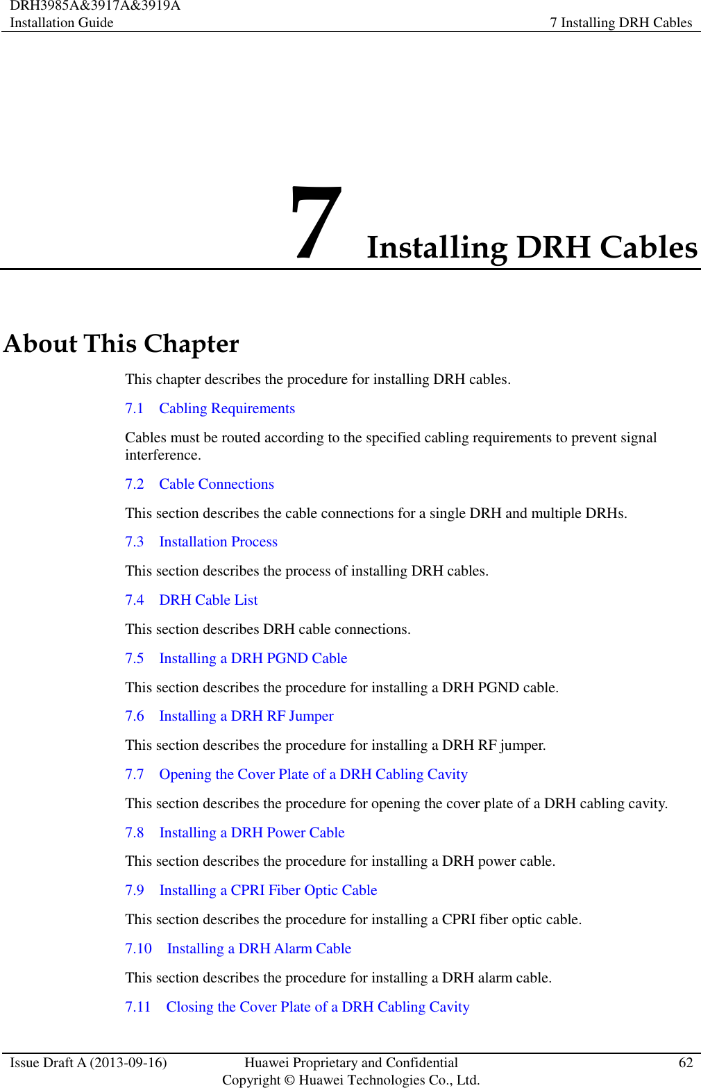
![DRH3985A&3917A&3919A Installation Guide 10 Appendix Issue Draft A (2013-09-16) Huawei Proprietary and Confidential Copyright © Huawei Technologies Co., Ltd. 90 Figure 10-7 Adding a tool-less female connector (pressfit type) to two core wires Step 5 Strip the specified length of the sheath off the power cable to expose the intact shield layer, as shown in Figure 10-8. Figure 10-8 Stripping the sheath off the power cable Each core wire is exposed outside the tool-less female connector (pressfit type) for 1.5 mm (0.059 [in.]), as shown in Figure 10-9.](https://usermanual.wiki/Huawei-Technologies/DRH3985A.User-Manual-II/User-Guide-2162187-Page-98.png)