Huawei Technologies DRH3985A Distributed Remote Head User Manual Hardware Description
Huawei Technologies Co.,Ltd Distributed Remote Head Hardware Description
Contents
- 1. User Manual
- 2. User Manual II
- 3. User Manual III
User Manual III

DBS3900 IBS
V100R001C02
DRH3985A&3917A&3919A&3919B
Hardware Description
Issue
Draft A
Date
2013-08-18
HUAWEI TECHNOLOGIES CO., LTD.

Issue Draft A (2013-08-18)
Huawei Proprietary and Confidential
Copyright © Huawei Technologies Co., Ltd.
i
Copyright © Huawei Technologies Co., Ltd. 2013. All rights reserved.
No part of this document may be reproduced or transmitted in any form or by any means without prior
written consent of Huawei Technologies Co., Ltd.
Trademarks and Permissions
and other Huawei trademarks are trademarks of Huawei Technologies Co., Ltd.
All other trademarks and trade names mentioned in this document are the property of their respective
holders.
Notice
The purchased products, services and features are stipulated by the contract made between Huawei and
the customer. All or part of the products, services and features described in this document may not be
within the purchase scope or the usage scope. Unless otherwise specified in the contract, all statements,
information, and recommendations in this document are provided "AS IS" without warranties, guarantees or
representations of any kind, either express or implied.
The information in this document is subject to change without notice. Every effort has been made in the
preparation of this document to ensure accuracy of the contents, but all statements, information, and
recommendations in this document do not constitute a warranty of any kind, express or implied.
Huawei Technologies Co., Ltd.
Address:
Huawei Industrial Base
Bantian, Longgang
Shenzhen 518129
People's Republic of China
Website:
http://www.huawei.com
Email:
support@huawei.com

DRH3985A&3917A&3919A&3919B
Hardware Description
About This Document
Issue Drafe A (2013-08-18)
Huawei Proprietary and Confidential
Copyright © Huawei Technologies Co., Ltd.
ii
About This Document
Purpose
This document provides reference for planning and deploying a DC DRH. It presents the
exterior and describes the ports, functions, cable types, connector specifications, and cable
connections of the DRH.
Product Version
The following table lists the product version related to this document.
Product Name
Product Version
DBS3900 IBS
V100R001C02
Scope of application
The following table lists the DRH related to this document.
DRH Name
DRH Version
DRH3985A
V100R001C02
DRH3917A
V100R001C02
DRH3919A
V100R001C02
DRH3919B
V100R001C02
Intended Audience
This document is intended for:
Base station installation engineers
System engineers
Site maintenance engineers

DRH3985A&3917A&3919A&3919B
Hardware Description
About This Document
Issue Drafe A (2013-08-18)
Huawei Proprietary and Confidential
Copyright © Huawei Technologies Co., Ltd.
iii
Organization
1 Changes in DRH3985A&3917A&3919A&3919B Hardware Description
This chapter describes the changes in DRH3985A&3917A&3919A&3919B Hardware Description.
2 DRH Introduction
This chapter describes the exterior and function of the DRH as well as the ports and indicators
on the DRH.
3 DRH Cables
This chapter describes DRH cables.
4 DRH Auxiliary Devices
This chapter describes DRH auxiliary devices.

DRH3985A&3917A&3919A&3919B
Hardware Description
Contents
Issue Draft A (2013-08-18)
Huawei Proprietary and Confidential
Copyright © Huawei Technologies Co., Ltd.
iv
Contents
About This Document .................................................................................................................... ii
Purpose ............................................................................................................................................................................... ii
Product Version ................................................................................................................................................................... ii
Scope of application ........................................................................................................................................................... ii
Intended Audience .............................................................................................................................................................. ii
Organization ...................................................................................................................................................................... iii
1 Changes in DRH 3985A&3917A&3919A&3919B Hardware Description ........................... 1
2 DRH Introduction ......................................................................................................................... 2
2.1 DRH Exterior ................................................................................................................................................................ 2
2.2 DRH Functions ............................................................................................................................................................. 3
2.3 DRH Technical Specifications ...................................................................................................................................... 4
2.4 DRH Ports ..................................................................................................................................................................... 4
2.5 DRH Indicators ............................................................................................................................................................. 7
2.6 Optical Modules............................................................................................................................................................ 8
2.7 DRH Antennas(Only for U.S.A and Canada) ............................................................................................................. 10
3 DRH Cables .................................................................................................................................. 11
3.1 DRH Cable List .......................................................................................................................................................... 11
3.2 DRH PGND Cable ...................................................................................................................................................... 12
3.3 DRH Power Cable ...................................................................................................................................................... 12
3.4 DRH Alarm Cable ....................................................................................................................................................... 13
3.5 CPRI Fiber Optic Cable .............................................................................................................................................. 15
3.6 DRH RF Jumper ......................................................................................................................................................... 18
4 DRH Auxiliary Devices ............................................................................................................. 20
4.1 IFS06 .......................................................................................................................................................................... 20
5 Appendix ...................................................................................................................................... 22
5.1 U.S.A Regulatory Compliance .................................................................................................................................... 22
5.2 Canada Regulatory Compliance ................................................................................................................................. 23
5.2.1 RSS-Gen statement .................................................................................................................................................. 23
5.2.2 RSS-102 statement: ................................................................................................................................................. 23

DRH3985A&3917A&3919A&3919B
Hardware Description
1 Changes in DRH 3985A&3917A&3919A&3919B
Hardware Description
Issue Draft A (2013-08-18)
Huawei Proprietary and Confidential
Copyright © Huawei Technologies Co., Ltd.
1
1 Changes in DRH
3985A&3917A&3919A&3919B Hardware
Description
This chapter describes the changes in DRH3985A&3917A&3919A&3919B Hardware Description.
Issue Draft A (2013-08-18)
This is the Draft A version.
DRH3985A&3917A&3919A&3919B
Hardware Description
2 DRH Introduction
Issue Draft A (2013-08-18)
Huawei Proprietary and Confidential
Copyright © Huawei Technologies Co., Ltd.
2
2 DRH Introduction
This chapter describes the function and exterior of the DRH as well as the ports and indicators
on the DRH.
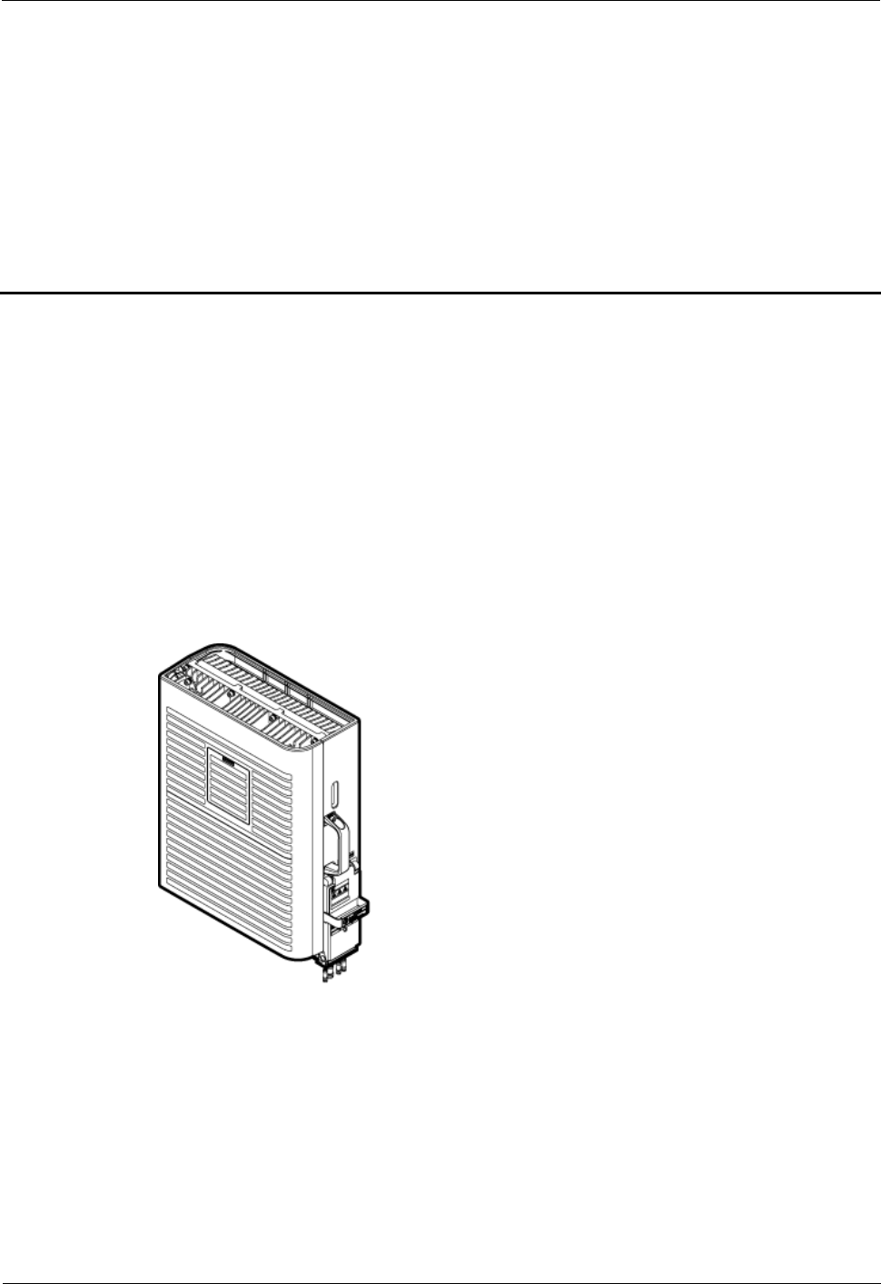
2.1 DRH Exterior
This section describes the exterior and dimensions of a DRH.
Figure 2-1 shows an DRH.
Figure 2-1 DRH exterior
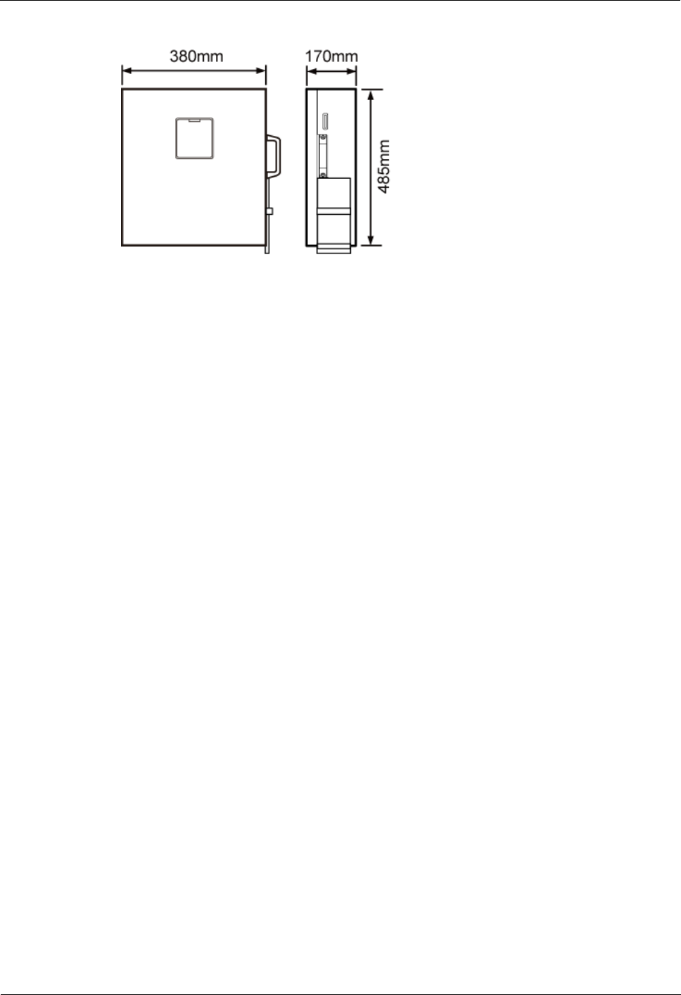
Figure 2-2 shows DRH dimensions.
DRH3985A&3917A&3919A&3919B
Hardware Description
2 DRH Introduction
Issue Draft A (2013-08-18)
Huawei Proprietary and Confidential
Copyright © Huawei Technologies Co., Ltd.
3
Figure 2-2 DRH dimensions
2.2 DRH Functions
This section describes the main functions of the DRH.
The Distributed Remote Head (DRH) performs the following functions:
Receives downlink baseband data from the DCU and sends uplink baseband data to the
DCU.
Receives RF signals from the antenna system, down-converts the signals to intermediate
frequency (IF) signals, amplifies the IF signals, and performs analog-to-digital
conversion. The transmit (TX) channel filters downlink signals, performs
digital-to-analog conversion, and up-converts RF signals to the TX band.
Multiplexes receive (RX) and TX signals on the RF channel, which enables these signals
to share the same antenna path. It also filters the RX and TX signals.
The DRH can be powered by the AC/DC power module. In this case, this DRH is called
AC DRH.
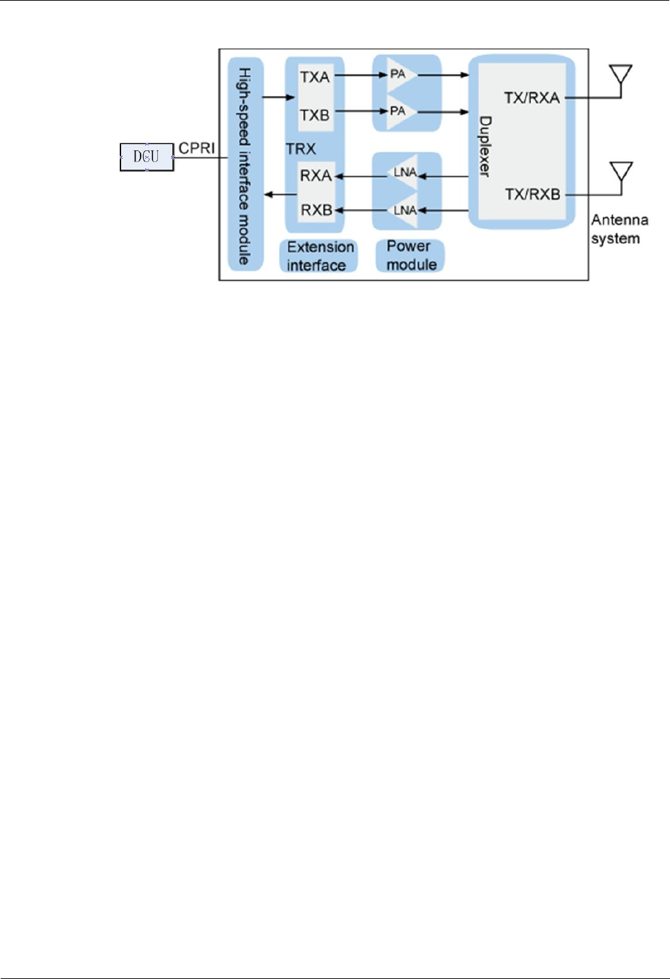
An DRH consists of a high-speed interface unit, signal processing unit, power amplifier, and
dual-duplexer. Figure 2-3 shows the logical structure of the DRH.
DRH3985A&3917A&3919A&3919B
Hardware Description
2 DRH Introduction
Issue Draft A (2013-08-18)
Huawei Proprietary and Confidential
Copyright © Huawei Technologies Co., Ltd.
4
Figure 2-3 Function structure of the DRH
2.3 DRH Technical Specifications
This section describes technical specifications of an DRH, including supported modes,
frequency bands, RF specifications, engineering specifications, and antenna capabilities.
For details about technical specifications of an DRH, see section "Technical Specifications "
in the DBS3900 IBS V100R001C02 Product Description.
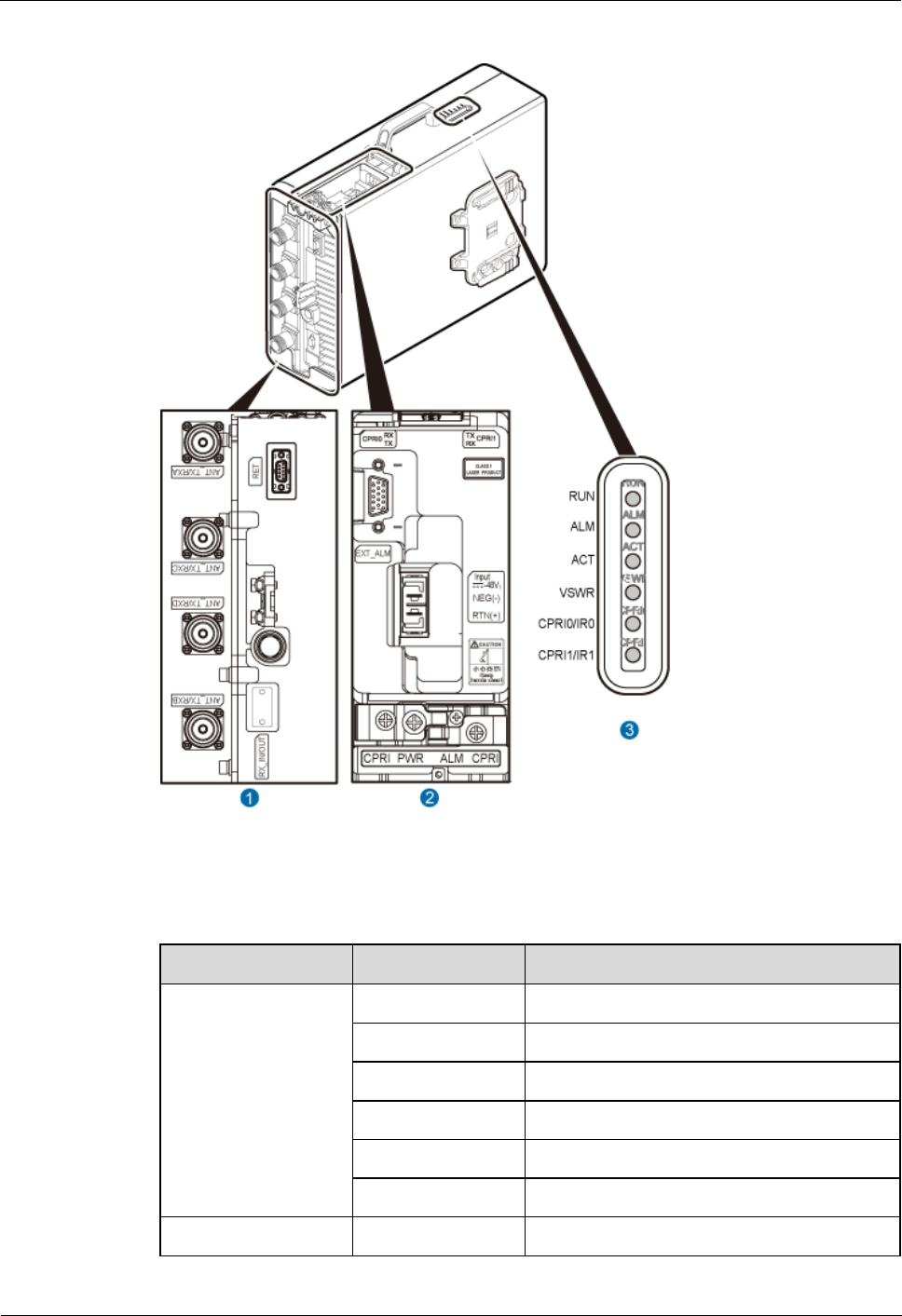
2.4 DRH Ports
This section describes ports on the DRH panels. A DRH has a bottom panel, cabling cavity
panel, and indicator panel.
Figure 2-4 shows the ports on the DRH panels.
DRH3985A&3917A&3919A&3919B
Hardware Description
2 DRH Introduction
Issue Draft A (2013-08-18)
Huawei Proprietary and Confidential
Copyright © Huawei Technologies Co., Ltd.
5
Figure 2-4 Ports on the DRH panels
Table 2-1 describes ports and indicators on the DRH panels.
Table 2-1 Ports and indicators on the DRH panels
Item
Silkscreen
Description
(1) Ports at the
bottom
ANT_TX/RXA
TX/RX port A
ANT_TX/RXB
TX/RX port B
ANT_TX/RXC
DRH not use this port
ANT_TX/RXD
DRH not use this port
RX_IN/OUT
DRH not use this port
RET
DRH not use this port
(2) Ports in the
RTN(+)
Power supply socket
DRH3985A&3917A&3919A&3919B
Hardware Description
2 DRH Introduction
Issue Draft A (2013-08-18)
Huawei Proprietary and Confidential
Copyright © Huawei Technologies Co., Ltd.
6
Item
Silkscreen
Description
cabling cavity
NEG(-)
CPRI0
Optical/electrical port 0
CPRI1
Optical/electrical port 1
EXT_ALM
Alarm monitoring port used for monitoring
one RS485 signal and two dry contact
signals
(3) Indicators
RUN
See 2.5 DRH Indicators.
ALM
ACT
VSWR
CPRI0/IR0
CPRI1/IR1
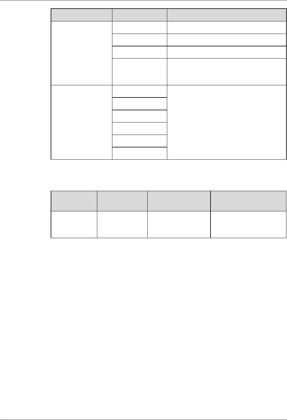
Table 2-2 describes how to use RF ports.
Table 2-2 Usage
TX/RX
Channel
Number of
Used RF Ports
Usage
Remarks
2T2R
2
ANT_TX/RXA and
ANT_TX/RXB used
together
A single sector
Figure2-5Shows the usage of the RF ports on a DRH.
DRH3985A&3917A&3919A&3919B
Hardware Description
2 DRH Introduction
Issue Draft A (2013-08-18)
Huawei Proprietary and Confidential
Copyright © Huawei Technologies Co., Ltd.
7
Figure 2-5 Usage
2.5 DRH Indicators
This section describes six indicators on a DRH. They indicate the running status.
For detailed positions of DRH indicators, see 2.4 DRH Ports.
Table 2-3 describes DRH indicators.
Table 2-3 DRH indicators
Indicator
Color
Status
Meaning
RUN
Green
Steady on
There is power supply, but the module is
faulty.
Steady off
There is no power supply, or the module is
faulty.
Blinking (on for
1s and off for 1s)
The board is functioning properly.
Blinking (on for
0.125s and off for
0.125s)
Software is being loaded to the module, or
the module is not started.
ALM
Red
Steady on
Alarms are generated, and the module must
be replaced.
Blinking (on for
1s and off for 1s)
Alarms are generated. The alarms may be
caused by the faults on the related boards or

DRH3985A&3917A&3919A&3919B
Hardware Description
2 DRH Introduction
Issue Draft A (2013-08-18)
Huawei Proprietary and Confidential
Copyright © Huawei Technologies Co., Ltd.
8
Indicator
Color
Status
Meaning
ports. Therefore, you need to locate the
fault before deciding whether to replace the
module.
Steady off
No alarm is generated.
ACT
Green
Steady on
The module is running properly with TX
channels enabled or the software is being
loaded without DRH running.
Blinking (on for
1s and off for 1s)
The module is running properly with TX
channels disabled.
VSWR
Red
Steady off
No Voltage Standing Wave Ratio (VSWR)
alarm is generated.
Steady on
A VSWR alarm is generated on one or
multiple ANT ports.
CPRI0/IR0
Red or
green
Steady green
The CPRI link is functioning properly.
Steady red
An optical module fails to transmit or
receive signals because the optical module
is faulty or the fiber optic cable is broken.
Blinking red (on
for 1s and off for
1s)
The CPRI link is out of lock because of a
failure in clock lock between two modes or
mismatched data rates over CPRI ports.
Steady off
The optical module cannot be detected, or
the optical module is powered off.
CPRI1/IR1
Red or
green
Steady green
The CPRI link is functioning properly.
Steady red
An optical module fails to transmit or
receive signals because the optical module
is faulty or the fiber optic cable is broken.
Blinking red (on
for 1s and off for
1s)
The CPRI link is out of lock because of a
failure in clock lock between two modes or
mismatched data rates over CPRI ports.
Steady off
The optical module cannot be detected, or
the optical module is powered off.
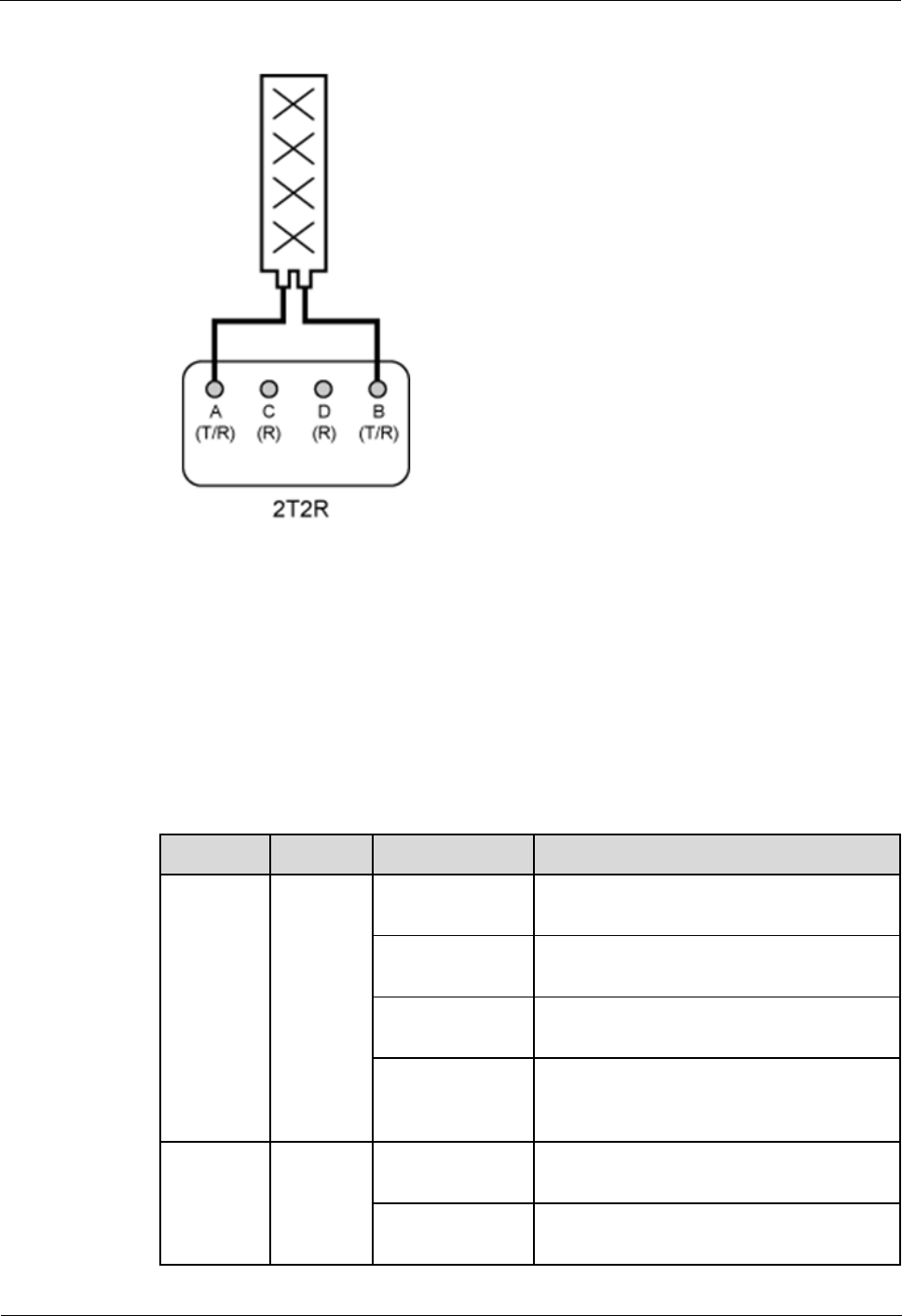
2.6 Optical Modules
An optical module transmits optical signals between an optical port and a fiber optic cable.
The exteriors of an optical module and the label on an optical module in this section are for reference
only. The actual exteriors may be different.
DRH3985A&3917A&3919A&3919B
Hardware Description
2 DRH Introduction
Issue Draft A (2013-08-18)
Huawei Proprietary and Confidential
Copyright © Huawei Technologies Co., Ltd.
9
Exterior
The following figure shows the exterior of an optical module.
Figure 2-6 Exterior of an optical module
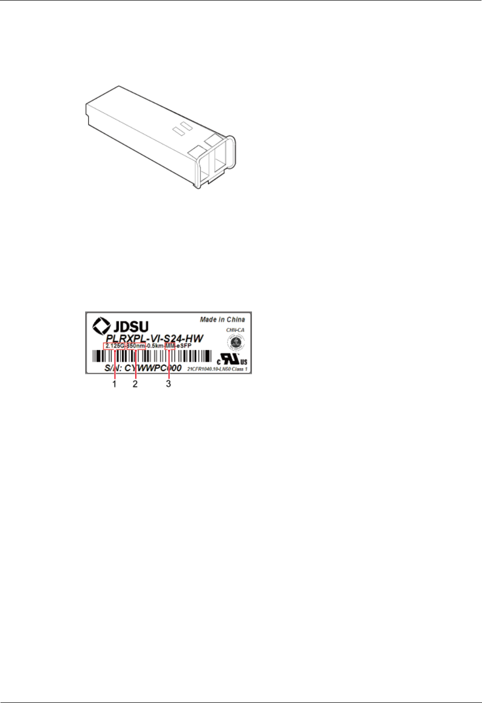
Label on an optical module
There is a label on each optical module, which provides information such as the rate,
wavelength, and transmission mode, as shown in the following figure.
Figure 2-7 Label on an optical module
(1) Rate
(2) Wavelength
(3) Transmission mode
Optical Module Type
Optical modules can be divided into single- and multimode optical modules, which can be
distinguished as follows:
The puller of a single-mode optical module is blue and the puller of a multimode optical
module is black or gray.
The transmission mode is displayed as "SM" on the label of a single-mode optical
module and "MM" on the label of a multimode optical module.

DRH3985A&3917A&3919A&3919B
Hardware Description
2 DRH Introduction
Issue Draft A (2013-08-18)
Huawei Proprietary and Confidential
Copyright © Huawei Technologies Co., Ltd.
10
2.7 DRH Antennas(Only for U.S.A and Canada)
Type
Description
Omnidirectional Ceiling
Antenna
Frequency:698MHz to 2700MHz;Maximum gain:
5dBi
Directional Ceiling Antenna
Frequency:698MHz to 2700MHz;Maximum gain:
6dBi
Wall Mount Antenna
Frequency:698MHz to 2700MHz;Maximum gain:
8dBi
Yagi Directional antenna
Frequency:698MHz to 2700MHz;Maximum gain:
11dBi
Directional Outdoor Antenna
Frequency:698MHz to 2700MHz;Maximum gain:
11.4dBi
Dual-polarized Omnidirectional
Ceiling Antenna
Frequency:698MHz to 2700MHz;Maximum gain:
5dBi
Dual-polarized Wall Mount
Antenna
Frequency:698MHz to 2700MHz;Maximum gain:
9dBi

DRH3985A&3917A&3919A&3919B
Hardware Description
3 DRH Cables
Issue Draft A (2013-08-18)
Huawei Proprietary and Confidential
Copyright © Huawei Technologies Co., Ltd.
11
3 DRH Cables
This chapter describes DRH cables.
3.1 DRH Cable List
This section describes DRH cable connections.
Table 3-1 lists DRH cables.
Table 3-1 DRH cables
Cable
One End
The Other End
Connector
Installation
Position
Connector
Installation
Position
3.2 DRH
PGND Cable
OT terminal
(M6, 16 mm2 or
0.025 in.2)
Ground
terminal on the
DRH
OT terminal
(M8, 16 mm2 or
0.025 in.2)
Ground terminal
on the ground bar
3.3 DRH
Power Cable
Tool-less female
connector
(pressfit type)
NEG(-) and
RTN(+) ports
on the DRH
Depending on
the power supply
equipment
External power
equipment
3.4 DRH
Alarm Cable
DB15 male
connector
EXT_ALM
port on the
DRH
Cord end
terminal
External alarm
device
3.5 CPRI
Fiber Optic
Cable
DLC connector
CPRI0 port on
the DRH
DLC connector
CPRI port on a
board in the DRH
3.6 DRH RF
Jumper
DIN male
connector
ANT_TX/RX
A,
ANT_TX/RX
B,
ANT_TX/RX
C, or
ANT_TX/RX
D port on the
DIN male
connector or
DIN female
connector
Antenna system
DRH3985A&3917A&3919A&3919B
Hardware Description
3 DRH Cables
Issue Draft A (2013-08-18)
Huawei Proprietary and Confidential
Copyright © Huawei Technologies Co., Ltd.
12
Cable
One End
The Other End
Connector
Installation
Position
Connector
Installation
Position
DRH
3.2 DRH PGND Cable
An DRH PGND cable connects a DRH and a ground bar, ensuring the proper grounding of
the DRH. The maximum length of a DRH PGND cable is 8 m (26.25 ft).
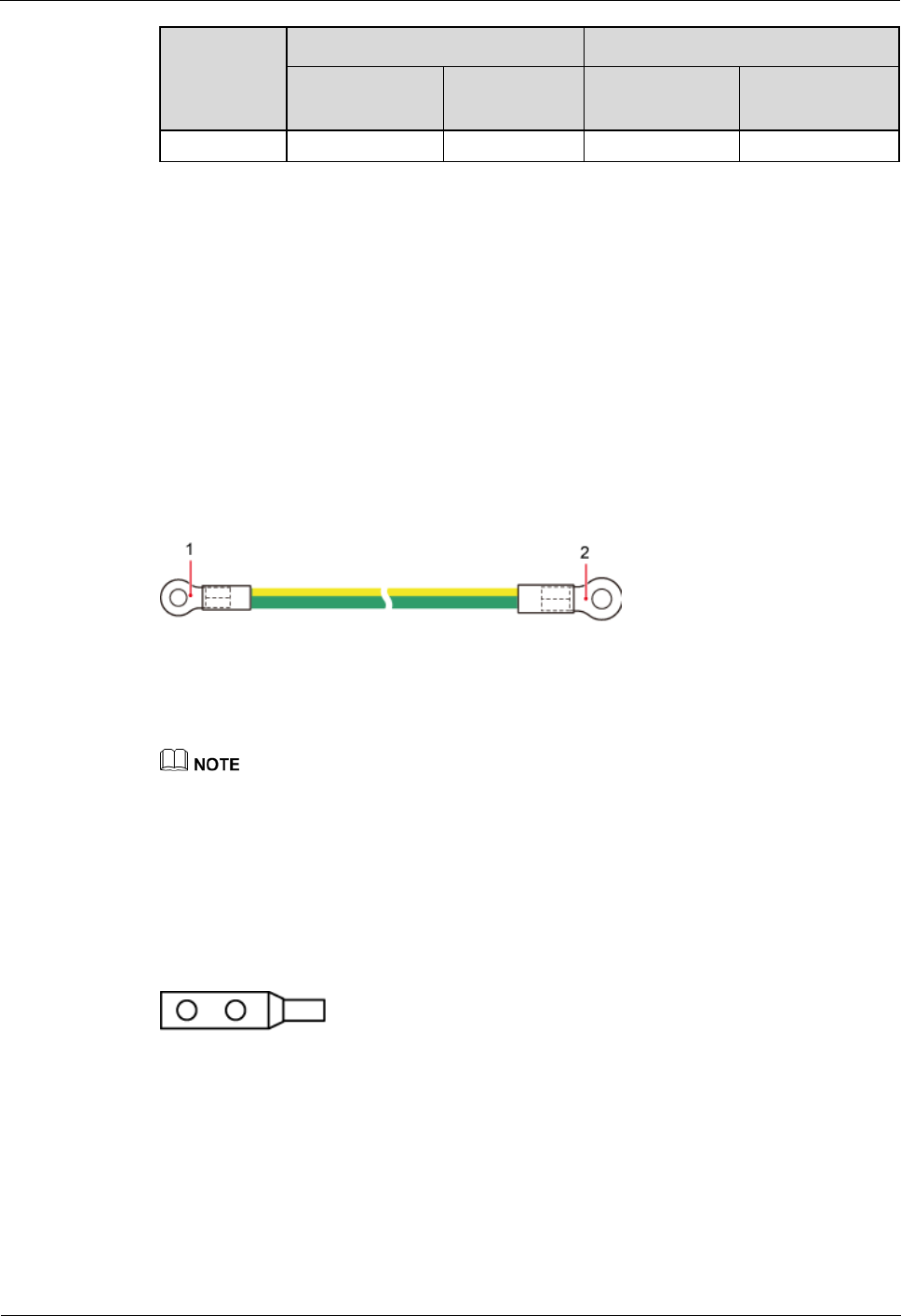
Exterior
A PGND cable is green or green and yellow with a cross-sectional area of 16 mm2 (0.025 in.2).
An OT terminal is installed at each end of the cable. Figure 3-1 shows a PGND cable.
Figure 3-1 PGND cable
(1) OT terminal (M6, 16 mm2 or 0.025 in.2)
(2) OT terminal (M8, 16 mm2 or 0.025 in.2)
If the customer prepares the PGND cable, a copper-core cable with a cross-sectional area of 16 mm2
(0.025 in.2) or larger is recommended.
One OT terminal must be added to each end of the PGND cable onsite.
You can determine the color of the cable and whether to use corresponding two-hole OT terminals
based on local regulations.
Figure 3-2 shows a two-hole OT terminal.
Figure 3-2 Two-hole OT terminal
3.3 DRH Power Cable
The DRH power cable is a -48 V DC shielded cable. It feeds -48 V DC power to a DRH. The
maximum length of a DRH power cable delivered with DRH s is 50 m (164.04 ft) by default.
DRH3985A&3917A&3919A&3919B
Hardware Description
3 DRH Cables
Issue Draft A (2013-08-18)
Huawei Proprietary and Confidential
Copyright © Huawei Technologies Co., Ltd.
13
The maximum length of power supply that a DRH power cable supports is 150 m (492.12 ft).
Contact Huawei engineers when a DRH power cable greater than 50 m (164.04 ft) is required.
If a power device provided by the customer is used, the recommended specification of the circuit
breaker on this power device is 15 A to 30 A.
Exterior
There are three types of DRH power cables in terms of cross-sectional areas: 5.3 mm2 (0.008
in.2) (10 AWG) and 8.2 mm2 (0.013 in.2) (8 AWG) complying with North American standards
and 6 mm2 (0.009 in.2) complying with European standards.
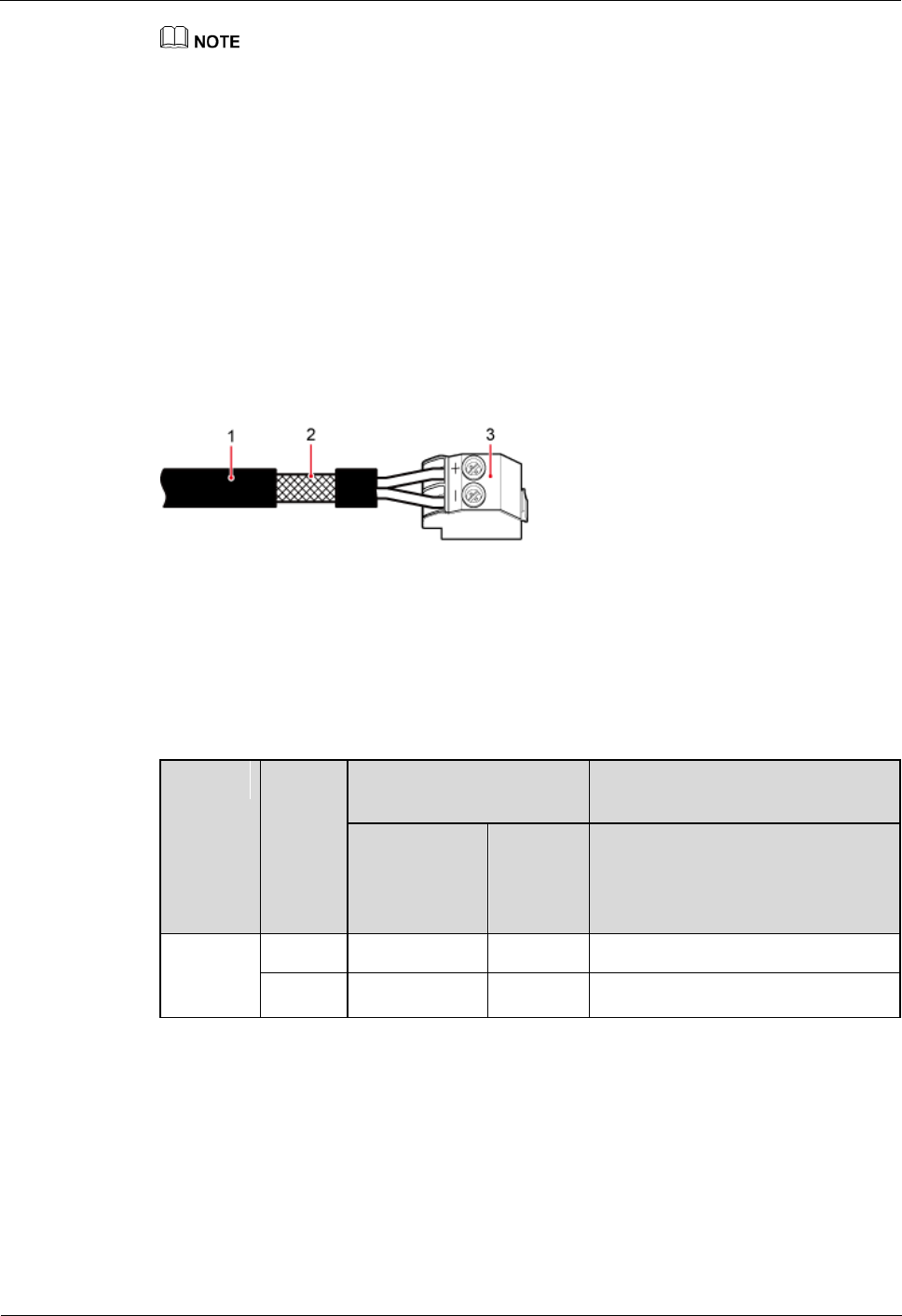
A tool-less female connector (pressfit type) needs to be added to one end of the DRH power
cable and a corresponding terminal needs to be added to the other end based on the
requirements of the connector on the external power device, as shown in Figure 3-3.
Figure 3-3 DRH power cable
(1) -48 V DC power cable
(2) Shield layer
(3) Tool-less female
connector (pressfit type)
Table 3-2 lists the specifications of a DRH power cable.
Table 3-2 Specifications of a DRH power cable
Cable
Wire
Wire Color in Most
Regions
Wire Color in Other Regions
North
American
Standard
Europea
n
Standar
d
UK
DRH
power
cable
RTN(+)
Black
Brown
Blue
NEG(-)
Blue
Blue
Gray
3.4 DRH Alarm Cable
The DRH alarm cable, a shielded straight-through cable, transmits alarm signals from an
external device to a DRH so that the base station monitors the operating status of external
devices. The DRH alarm cable is 5 m (16.4 ft).
DRH3985A&3917A&3919A&3919B
Hardware Description
3 DRH Cables
Issue Draft A (2013-08-18)
Huawei Proprietary and Confidential
Copyright © Huawei Technologies Co., Ltd.
14
Exterior
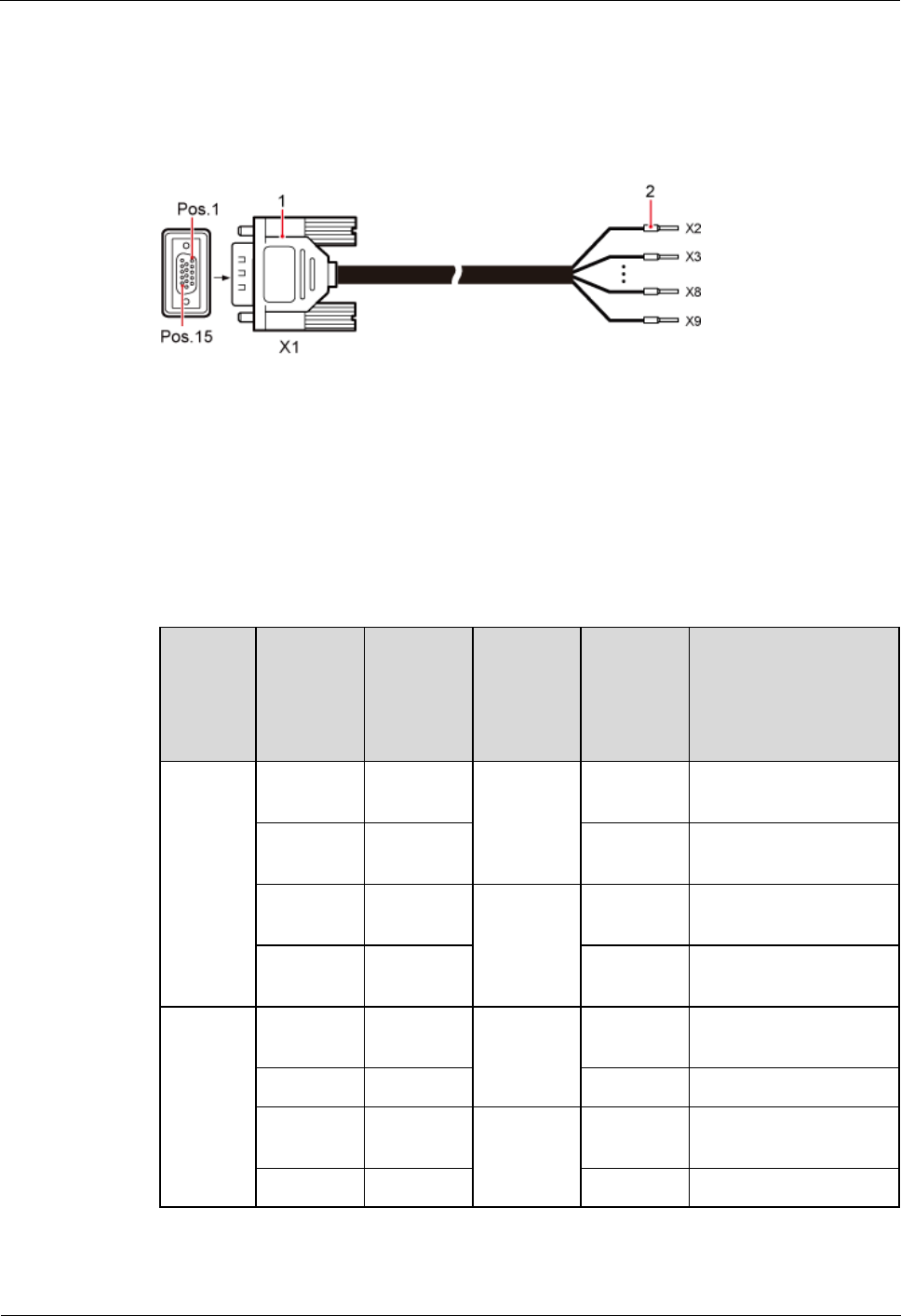
An alarm cable has a DB15 male connector at one end and eight cord end terminals at the
other end, as shown in Figure 3-4.
Figure 3-4 Alarm cable
(1) DB15 male connector
(2) Cord end terminal
Pin Assignment
Table 3-3 describes the pin assignment for the wires of a DRH alarm cable.
Table 3-3 Pin assignment for the wires of a DRH alarm cable
DRH
Alarm
Port
Pin of the
DB15
Male
Connecto
r
Color
Type
Cord End
Terminal
Description
Dry
contact
X1.2
White and
blue
Twisted
pair
X2
SWITCH_INPUT0+
X1.3
Blue
X3
SWITCH_INPUT0-
(GND)
X1.6
White and
orange
Twisted
pair
X4
SWITCH_INPUT1+
X1.7
Orange
X5
SWITCH_INPUT1-
(GND)
RS485
X1.10
White and
green
Twisted
pair
X6
APM RX-
X1.11
Green
X7
APM RX+
X1.13
White and
brown
Twisted
pair
X8
APM TX-
X1.14
Brown
X9
APM TX+
DRH3985A&3917A&3919A&3919B
Hardware Description
3 DRH Cables
Issue Draft A (2013-08-18)
Huawei Proprietary and Confidential
Copyright © Huawei Technologies Co., Ltd.
15
3.5 CPRI Fiber Optic Cable
CPRI fiber optic cables are classified into multimode fiber optic cables and single-mode fiber
optic cables. They transmit CPRI signals.
Multimode fiber optic cables connect the DCU and DRH or interconnect two DRHs. The
maximum length of the multimode fiber optic cable between the DCU and DRH is 150 m
(492.12 ft) and the multimode fiber optic cable between two DRHs has a fixed length of 10 m
(32.81 ft).
A single-mode fiber optic cable consists of the single-mode pigtail and trunk single-mode
fiber optic cable, and the single-mode pigtail and trunk single-mode fiber optic cable are
interconnected using the ODF. The maximum length of the single-mode pigtail is 20 m (65.62
ft) on DCU side and 70 m (229.66 ft) on DRH side.
The ODF and trunk single-mode fiber optic cable are provided by the customer and must comply
with the ITU-T G.652 standard.
The ODF is an outdoor transfer box for fiber optic cables, which interconnects the single-mode
pigtail and trunk single-mode fiber optic cable.
A multimode fiber optic cable and a single-mode fiber optic cable are connected to a multimode
optical module and a single-mode optical module, respectively.
Exterior
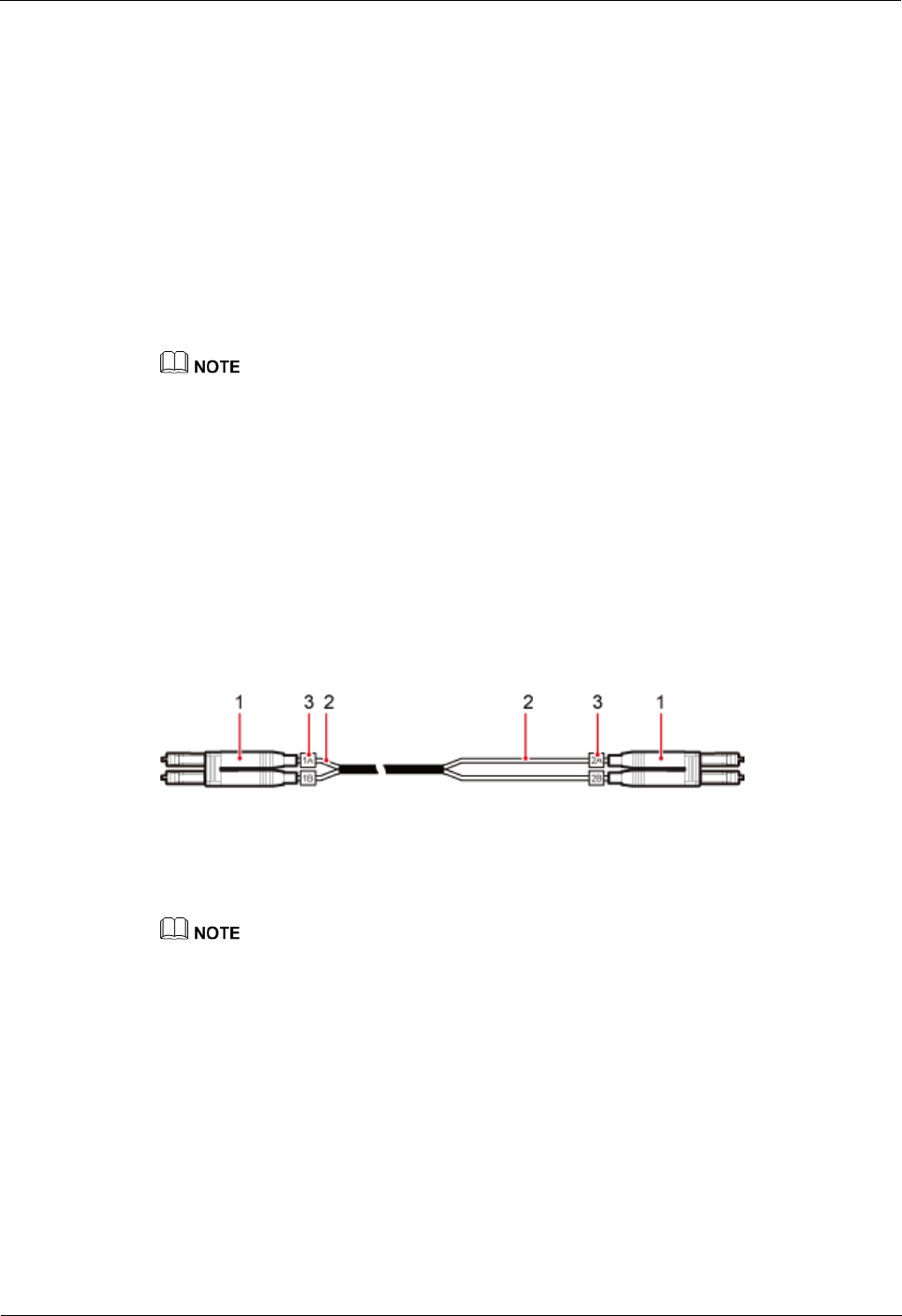
Multimode fiber optic cable: The multimode fiber optic cable has a DLC connector at each
end, as shown in Figure 3-5.
Figure 3-5 Multimode fiber optic cable
(1) DLC connector
(2) Breakout cable
(3) Label on the breakout cable
When a multimode fiber optic cable connects a DCU and a DRH, the breakout cable on the DCU
side is 0.34 m (1.12 ft) and the breakout cable on the DRH side is 0.03 m (0.098 ft).
When a multimode fiber optic cable connects two DRHs, the breakout cable on both sides is 0.03 m
(0.098 ft).
Figure 3-6 shows the connection of the multimode fiber optic cable between a DCU and a
DRH.
DRH3985A&3917A&3919A&3919B
Hardware Description
3 DRH Cables
Issue Draft A (2013-08-18)
Huawei Proprietary and Confidential
Copyright © Huawei Technologies Co., Ltd.
16
Figure 3-6 Connection of the multimode fiber optic cable between a DCU and a DRH
(1) Multimode fiber optic cable between a DCU and a DRH
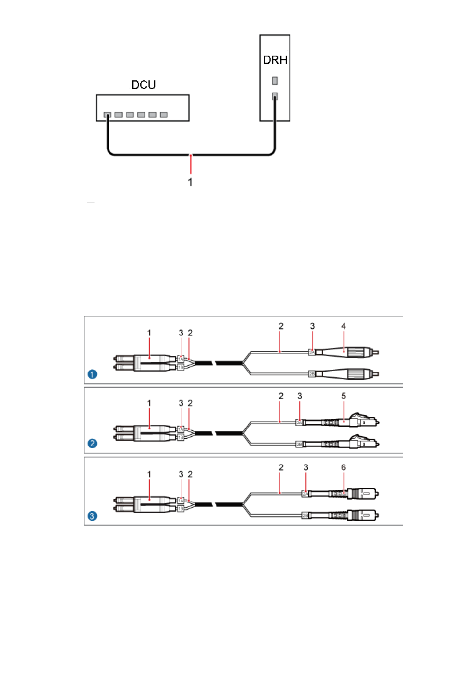
Single-mode pigtail: The single-mode pigtail has a DLC connector at one end and an FC, LC,
or SC connector at the other end, as shown in Figure 3-7.
Figure 3-7 Single-mode pigtail
(1) DLC
connector
(2)
Breakout
cable
(3) Label on the
breakout cable
(4) FC
connector
(5) LC
connector
(6) SC
connector
DRH3985A&3917A&3919A&3919B
Hardware Description
3 DRH Cables
Issue Draft A (2013-08-18)
Huawei Proprietary and Confidential
Copyright © Huawei Technologies Co., Ltd.
17
When a single-mode pigtail connects a DCU and an ODF, the breakout cables on the DCU side and
ODF side are 0.34 m (1.12 ft) and 0.8 m (2.62 ft), respectively.
When a single-mode pigtail connects a DRH and an ODF, the breakout cables on the DRH side and
ODF side are 0.03 m (0.098 ft) and 0.8 m (2.62 ft), respectively.
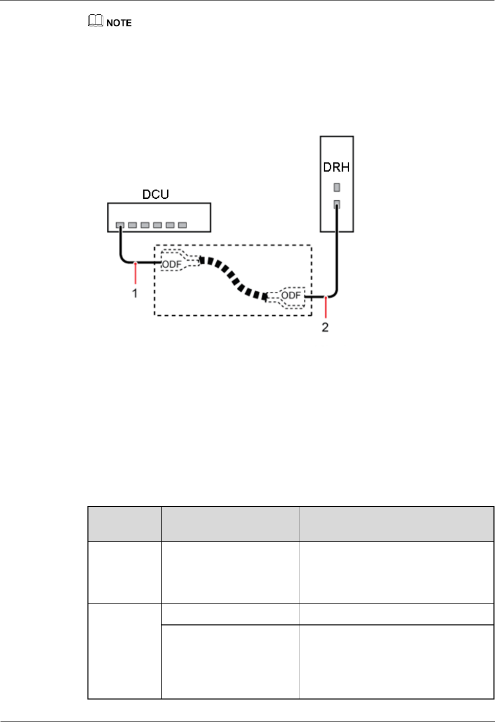
Figure 3-8 shows the connection of the single-mode pigtail.
Figure 3-8 Connection of the single-mode pigtail
(1) Single-mode pigtail between a DCU
and an ODF
(2) Single-mode pigtail between a DRH
and an ODF
Selection Principles
The following table describes the principles for selecting CPRI fiber optic cables.
Table 3-4 Principles for selecting CPRI fiber optic cables
Remote
Distance
Selection Principle
Remarks
Less than or
equal to 100
m (328.08 ft)
Multimode fiber optic cable
Connects the DCU and DRH
When it connects two DRHs, the distance
between the two DRHs must be equal to
or less than 10 m (32.81 ft).
Greater than
100 m
(328.08 ft)
and equal to
or less than
150 m
(492.12 ft)
Multimode fiber optic cable
Connects the DCU and DRH
Recommended: single-mode
fiber optic cable
(single-mode pigtail and
trunk single-mode fiber optic
cable)
The single-mode pigtail at the DRH or
DCU side is connected to the trunk
single-mode fiber optic cable using the
ODF.

DRH3985A&3917A&3919A&3919B
Hardware Description
3 DRH Cables
Issue Draft A (2013-08-18)
Huawei Proprietary and Confidential
Copyright © Huawei Technologies Co., Ltd.
18
Remote
Distance
Selection Principle
Remarks
Greater than
150 m
(492.12 ft)
Single-mode fiber optic cable
(single-mode pigtail and
trunk single-mode fiber optic
cable)
Pin Assignment
Table 3-5 describes the labels on and recommended connections for the breakout cables of a
CPRI fiber optic cable.
Table 3-5 Labels on and recommended connections for the breakout cables of a CPRI fiber optic
cable
Label
Installation Position
Multimode Fiber
Optic Cable
Between a DCU
and an DRH
Multimode Fiber
Optic Cable
Between Two
DRHs
Single-Mode Pigtail
1A
CPRI RX port on the
DRH
CPRI RX port on
DRH 1
RX port on the DCU
or CPRI RX port on
the DRH
1B
CPRI TX port on the
DRH
CPRI TX port on
DRH 1
TX port on the DCU or
CPRI TX port on the
DRH
2A
TX port on the DCU
CPRI TX port on
DRH 0
ODF
2B
RX port on the DCU
CPRI RX port on
DRH 0
ODF
3.6 DRH RF Jumper
The 1/2" DRH RF jumper transmits and receives RF signals between a DRH and an antenna.
A fixed-length RF jumper used by an DRH is 2 m (6.56 ft), 3 m (9.84 ft), 4 m (13.12 ft), 6 m
(19.68 ft), or 10 m (32.81 ft). A variable-length RF jumper used by a DRH has a maximum
length of 10 m (32.81 ft).

DRH3985A&3917A&3919A&3919B
Hardware Description
3 DRH Cables
Issue Draft A (2013-08-18)
Huawei Proprietary and Confidential
Copyright © Huawei Technologies Co., Ltd.
19
When the distance between an DRH and an antenna is less than 10 m (32.81 ft), one end of the RF
jumper is connected to the ANT-TX/RXA or ANT-TX/RXB port at the bottom of the DRH, and the
other end is connected to the antenna.
When the distance between a DRH and an antenna is greater than 10 m (32.81 ft), one end of the RF
jumper is connected to a feeder, and the other end is connected to the antenna.
If the customer prepares the RF jumper, the length of the RF jumper should be as short as possible
and not exceed 2 m (6.56 ft.).
Exterior
An RF jumper has a DIN male connector at one end and a customized connector at the other
end.
Figure 3-9 shows an RF jumper with a DIN male connector at each end.
Figure 3-9 RF jumper
(1) DIN male connector
DRH3985A&3917A&3919A&3919B
Hardware Description
4 DRH Auxiliary Devices
Issue Draft A (2013-08-18)
Huawei Proprietary and Confidential
Copyright © Huawei Technologies Co., Ltd.
20
4 DRH Auxiliary Devices
This chapter describes DRH auxiliary devices.
4.1 IFS06
An Indoor Floor installation Support (IFS06) is used for installing indoor DRHs.
Exterior
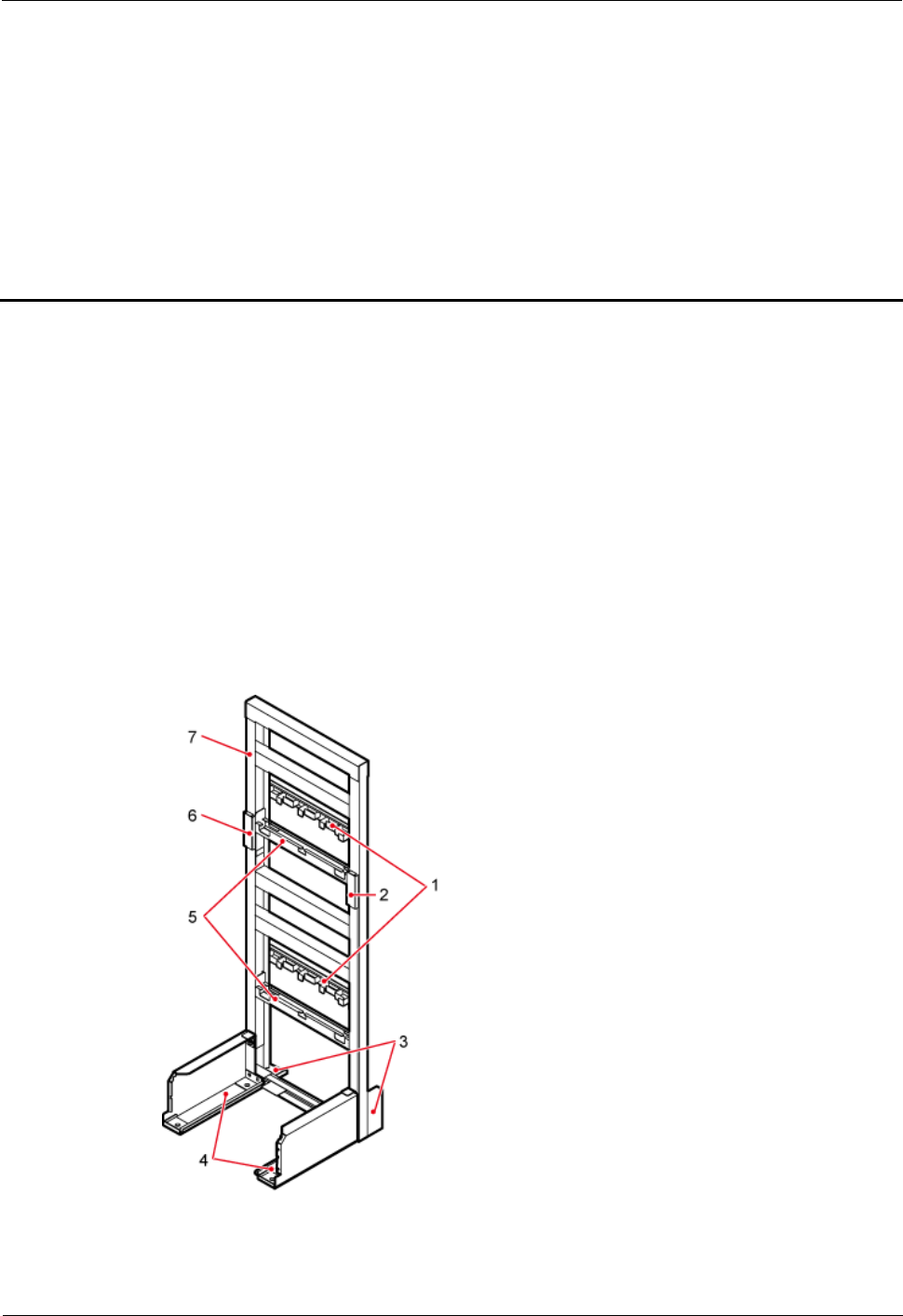
Figure 4-1 shows an IFS06.
Figure 4-1 IFS06

DRH3985A&3917A&3919A&3919B
Hardware Description
4 DRH Auxiliary Devices
Issue Draft A (2013-08-18)
Huawei Proprietary and Confidential
Copyright © Huawei Technologies Co., Ltd.
21
(1) Cable tray
(2) Ground bar 2
(3) Rear foot
(4) Front foot
(5) Adjustable beam
(6) Ground bar 1
(7) Main frame
-
Function
It can be installed on the ground.
It supports the installation of six DRHs.
The upper and lower adjustable beams on an IFS06 can be moved up and down to fit for
heights of DRHs.
Specifications
Table 4-1 describes IFS06 specifications.
Table 4-1 IFS06 specifications
Item
Specification
Dimensions (H x W x D)
1730 mm (79 in.) x 600 mm (23.62 in.) x 600 mm (23.62
in.)
Weight
45 kg (99.23 lb)

DRH3985A&3917A&3919A&3919B
Hardware Description
5 Appendix
Issue Draft A (2013-08-18)
Huawei Proprietary and Confidential
Copyright © Huawei Technologies Co., Ltd.
22
5 Appendix
5.1 U.S.A Regulatory Compliance
This device complies with Part 15 of the FCC Rules. Operation is subject to the following two
conditions:
This device does not cause harmful interference.
This device must accept any interference received, including interference that may cause
undesired operation.
If this device is modified without authorization from Huawei, the device may no longer
comply with FCC requirements for Class B digital devices. In that a case, your right to use the
device may be limited by FCC regulations. Moreover, you may be required to correct any
interference to radio or television communications at your own expense.
This device has been tested and found to comply with the limits for a Class B digital device,
pursuant to Part 15 of the FCC rules. These limits are designed to provide reasonable
protection against harmful interference in a residential installation.
This device generates, uses and radiates radio frequency energy. If it is not installed and used
in accordance with the instructions, it may cause harmful interference to radio
communications.
However, there is no guarantee that interference will not occur in a particular installation. If
this device does cause harmful interference to radio or television reception, which can be
determined by turning the device off and on, the user may take one or more of the following
measures:
Reorient or relocate the receiving antenna.
Reinforce the separation between the device and receiver.
Connect the device into an outlet on a circuit different from that to which the receiver is
connected.
Consult the dealer or an experienced radio or TV technician for assistance.
This equipment complies with FCC RF radiation exposure limits set forth for an uncontrolled
environment. This transmitter must not be co-located or operating in conjunction with any
other antenna or transmitter. The minimum installed and operated distance between the
radiator and your body of each model as below.
For DRH3985A, please keep 2.54m or more.
For DRH3917A, please keep 2.17m or more.

DRH3985A&3917A&3919A&3919B
Hardware Description
5 Appendix
Issue Draft A (2013-08-18)
Huawei Proprietary and Confidential
Copyright © Huawei Technologies Co., Ltd.
23
For DRH3919A, please keep 2.24m or more.
WARNING: This is NOT a CONSUMER device. It is designed for installation by FCC
LICENSEES and QUALIFIED INSTALLERS. You MUST have an FCC LICENSE or
express consent of an FCC Licensee to operate this device. Unauthorized use may result in
significant forfeiture penalties, including penalties in excess of $100,000 for each continuing
violation.
The manufacturer is not responsible for any radio or TV interference caused by unauthorized
modifications to this equipment. Such modifications could void the user authority to operate
the equipment.
.
5.2 Canada Regulatory Compliance
5.2.1 RSS-Gen statement
This device complies with Industry Canada licence-exempt RSS standard(s).
Operation is subject to the following two conditions: (1) this device may not cause
interference, and (2) this device must accept any interference, including interference that may
cause undesired operation of the device.
Le présent appareil est conforme aux CNR d'Industrie Canada applicables aux appareils radio
exempts de licence. L'exploitation est autorisée aux deux conditions suivantes : (1) l'appareil
ne doit pas produire de brouillage, et (2) l'utilisateur de l'appareil doit accepter tout brouillage
radioélectrique subi, même si le brouillage est susceptible d'en compromettre le
fonctionnement.
5.2.2 RSS-102 statement:
The device meets the exemption from the routine evaluation limits in section 2.5 of RSS 102
and compliance with RSS-102 RF exposure, users can obtain Canadian information on RF
exposure and compliance.
Le dispositif rencontre l'exemption des limites courantes d'évaluation dans la section 2.5 de
RSS 102 et la conformité à l'exposition de RSS-102 rf, utilisateurs peut obtenir l'information
canadienne sur l'exposition et la conformité de rf.
This equipment complies with IC radiation exposure limits set forth for an uncontrolled
environment. This transmitter must not be co-located or operating in conjunction with any
other antenna or transmitter. The minimum installed and operated distance between the
radiator and your body of each model as below.
For DRH3985A, please keep 2.54m or more.
For DRH3917A, please keep 2.17m or more.

DRH3985A&3917A&3919A&3919B
Hardware Description
5 Appendix
Issue Draft A (2013-08-18)
Huawei Proprietary and Confidential
Copyright © Huawei Technologies Co., Ltd.
24
For DRH3919A, please keep 2.24m or more.
Cet équipement est conforme à l'exposition aux rayonnements IC limites établies pour
unenvironnement non contrôlé. Cet émetteur ne doit pas être Co-placé ou ne fonctionnant en
même temps qu'aucune autre antenne ou émetteur.La distance d’installation et d’opération
entre le radiateur et votre corps de chaque équipement doit être au minimum :
Pour DRH3985A, 2.54m ou plus.
Pour DRH3917A, 2.17m ou plus.
Pour DRH3919A, 2.24m ou plus.
Some Information
(a) The nominal passband gain is 37dB;
(b) The nominal bandwidth for each band is as follows:
850M (DRH3985A): 27.95MHz
AWS (DRH3917A): 48.05MHz
1900M (DRH3919A): 63.07MHz;
(c) The rated mean output power is 2*20W;
(d) The input and output impedance are 50Ω;
(e) The following notice:”The Manufacture’s rated output power of this equipment is for
single carrier operation. For situations when multiple carrier signals are present, the
rating would have to be reduced by 3.5dB, especially where the output signal is
re-radiated and can cause interference to adjacent band users. This power reduction is to
be by means of input power or gain reduction and not by an attenuator at the output of
the device.”