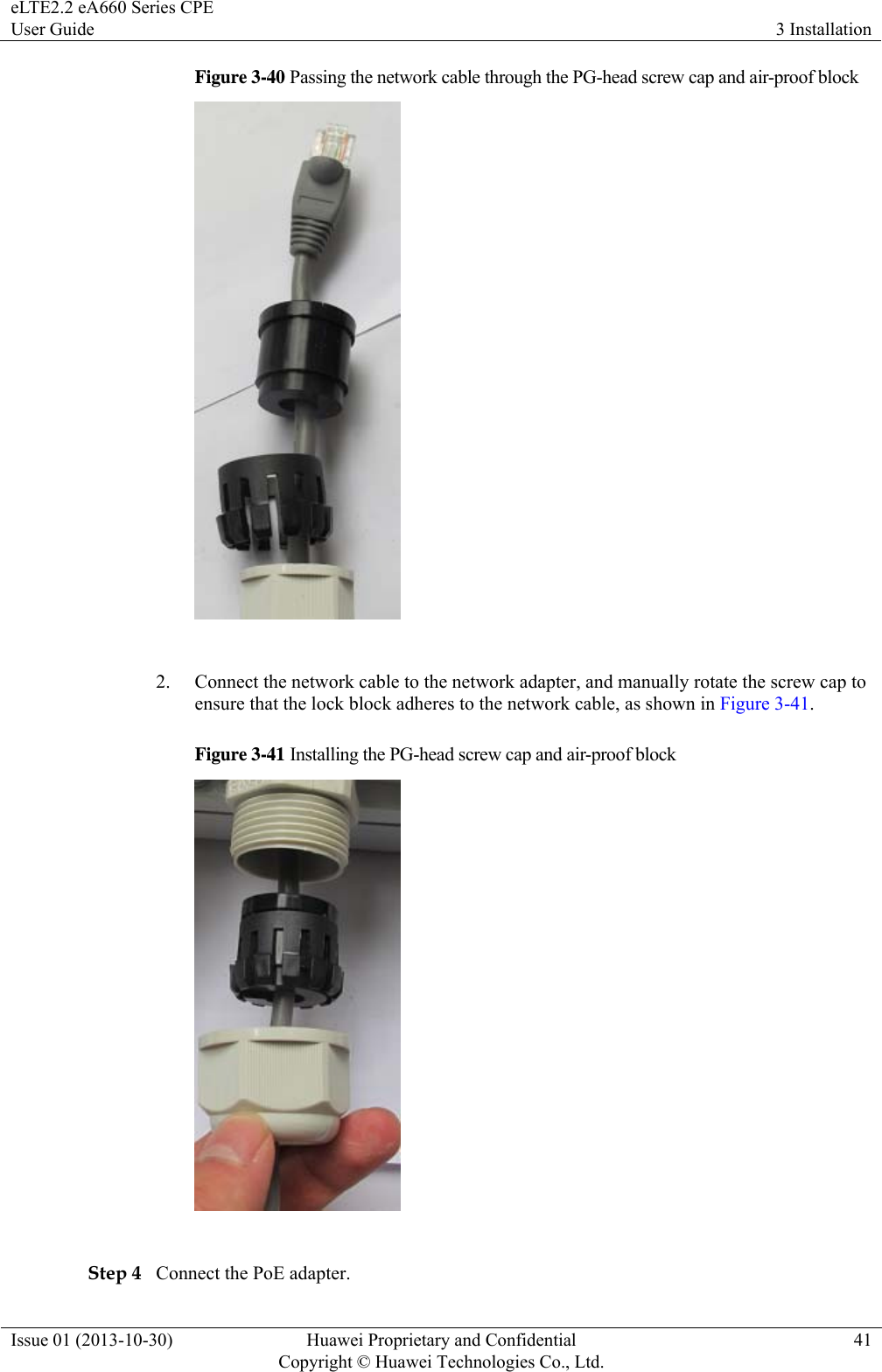
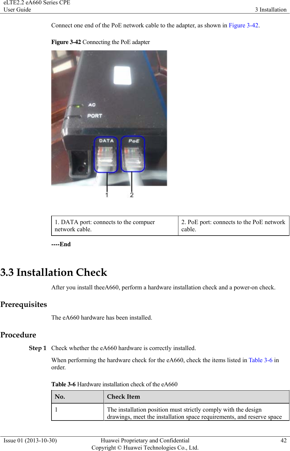
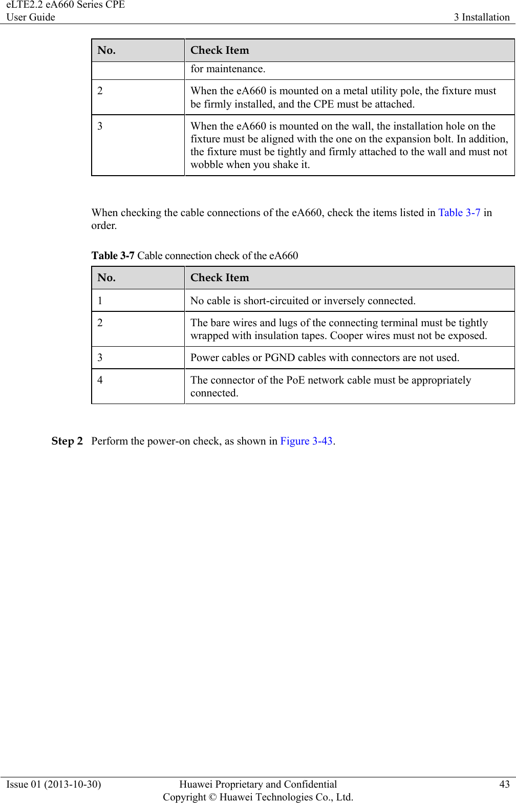
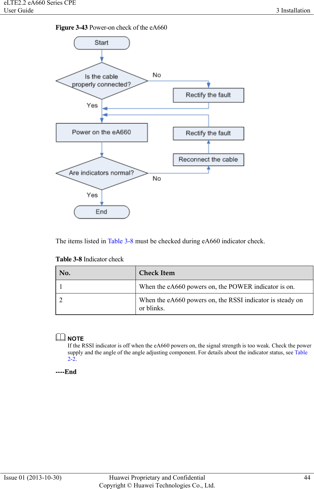
Huawei Technologies EA660-135 LTE CPE User Manual

Huawei Technologies Co.,Ltd LTE CPE

User Manual

      eLTE2.2 eA660 Series CPE  User Guide  Issue 01 Date 2013-10-30 HUAWEI TECHNOLOGIES CO., LTD.
 Issue 01 (2013-10-30)  Huawei Proprietary and Confidential         Copyright © Huawei Technologies Co., Ltd. i  Copyright © Huawei Technologies Co., Ltd. 2013. All rights reserved. No part of this document may be reproduced or transmitted in any form or by any means without prior written consent of Huawei Technologies Co., Ltd.  Trademarks and Permissions   and other Huawei trademarks are trademarks of Huawei Technologies Co., Ltd. All other trademarks and trade names mentioned in this document are the property of their respective holders.  Notice The purchased products, services and features are stipulated by the contract made between Huawei and the customer. All or part of the products, services and features described in this document may not be within the purchase scope or the usage scope. Unless otherwise specified in the contract, all statements, information, and recommendations in this document are provided "AS IS" without warranties, guarantees or representations of any kind, either express or implied. The information in this document is subject to change without notice. Every effort has been made in the preparation of this document to ensure accuracy of the contents, but all statements, information, and recommendations in this document do not constitute a warranty of any kind, express or implied.     Huawei Technologies Co., Ltd. Address:  Huawei Industrial Base Bantian, Longgang Shenzhen 518129 People's Republic of China Website:  http://www.huawei.com Email:  support@huawei.com
eLTE2.2 eA660 Series CPE User Guide  About This Document Issue 01 (2013-10-30)  Huawei Proprietary and Confidential         Copyright © Huawei Technologies Co., Ltd.ii About This Document Overview This document describes the hardware, functions, installation, configuration, operation and maintenance (OM) of the eA660 series customer premises equipment (CPE). Product Version Product Name  Product Version eA660 Series CPE  V100R001C01  Intended Audience This document is intended for: z System engineers z Product engineers z Technical support engineers Change History Issue 01 (2013-10-30) This is the first commercial release.
eLTE2.2 eA660 Series CPE User Guide  Contents Issue 01 (2013-10-30)  Huawei Proprietary and Confidential         Copyright © Huawei Technologies Co., Ltd.iii Contents About This Document .................................................................................................................... ii 1 Overview ......................................................................................................................................... 1 1.1 Product Introduction ..................................................................................................................................................... 1 1.2 Application Scenarios ................................................................................................................................................... 2 1.3 Hardware Specifications ............................................................................................................................................... 5 1.4 Antenna Specifications ................................................................................................................................................. 6 2 Hardware ........................................................................................................................................ 7 2.1 eA660 Hardware ........................................................................................................................................................... 7 2.2 eA660 Cables .............................................................................................................................................................. 10 2.2.1 PoE Network Cable ................................................................................................................................................. 10 2.2.2 Ground Cable ........................................................................................................................................................... 10 3 Installation.................................................................................................................................... 12 3.1 Installation Preparation ............................................................................................................................................... 12 3.2 Installation Procedure ................................................................................................................................................. 13 3.2.1 Mounting on a Utility Pole (Without an Angle Adjusting Component) ................................................................... 13 3.2.2 Mounting on a Utility Pole (with an Angle Adjusting Component) ........................................................................ 19 3.2.3 Mounting on the Wall (Without an Angle Adjusting Component) ........................................................................... 26 3.2.4 Mounting on the Wall (with an Angle Adjusting Component)................................................................................. 32 3.2.5 Cable Connection ..................................................................................................................................................... 38 3.3 Installation Check ....................................................................................................................................................... 42 4 Configuring the eA660 ............................................................................................................... 45 5 Maintenance ................................................................................................................................. 46 5.1 Maintenance Preparation ............................................................................................................................................ 46 5.2 Fault Diagnosis ........................................................................................................................................................... 46
eLTE2.2 eA660 Series CPE User Guide  1 Overview Issue 01 (2013-10-30)  Huawei Proprietary and Confidential         Copyright © Huawei Technologies Co., Ltd.1 1 Overview 1.1 Product Introduction HUAWEI eA660 is a piece of customer premises equipment (CPE) that functions as the long term evolution (LTE) wireless gateway. It implements the conversion between LTE wireless data and wired Ethernet data and supports data backhaul. The eA660 series can be used independently and deployed outdoors.   The eA660 supports the LTE R8 standards and provides the following services: z Data services The eA660 series uses LTE broadband technologies to support high-speed broadband network access, data backhaul, and video surveillance. z Small-scale local area network (LAN) The eA660 series can connect to external concentrators and Ethernet switches or routers to set up a LAN with multiple computers. When terminal devices on the LAN connect to the eA660 using network cables, the terminal devices can provide data services.   z Security services The eA660 series supports the firewall and PIN password, which protects your computers when you access the Internet. z Firewall services The eA660 series supports the following firewall services: − Firewall enabling or disabling: enables or disables firewalls. − Media access control (MAC) address filtering: prevents certain MAC addresses from accessing the computers on a LAN. − IP address filtering: blocks certain IP addresses from accessing the local computers. − URL filtering: prevents computers from accessing certain URLs. z Local and remote management and maintenance The eA660 series can be locally configured in the local city to implement device management and network configuration, thereby ensuring stable operation of the device.       Warning
eLTE2.2 eA660 Series CPE User Guide  1 Overview Issue 01 (2013-10-30)  Huawei Proprietary and Confidential         Copyright © Huawei Technologies Co., Ltd.2 z This device complies with Part 15 of the FCC Rules. Operation is subject to the following two conditions: (1) This device may not cause harmful interference, and (2) this device must accept any interference received, including interference that may cause undesired operation.    z FCC Caution To assure continued compliance, any changes or modifications not expressly approved by the party responsible for compliance could void the user's authority to operate this equipment.  z FCC Radiation Exposure Statement To comply with FCC RF exposure requirements in section 1.1307, a minimum separation distance of 20cm is required between the antenna and all public persons.  1.2 Application Scenarios The eA660 provides wireless broadband and wired Ethernet data services. The eA660 is deployed outdoors and provides wireless gateway services. The eA660 can be deployed independently or used in conjunction with the eA100, which is deployed indoors and connected to the eA660 using a network cable, enabling the eA660 to provide Wi-Fi and other Internet services.    For details about the eA100, see the eLTE2.1 eA100 Series CPE Product Description. Figure 1-1 shows an application scenario in which the eA660 is used with the eA100.
eLTE2.2 eA660 Series CPE User Guide  1 Overview Issue 01 (2013-10-30)  Huawei Proprietary and Confidential         Copyright © Huawei Technologies Co., Ltd.3 Figure 1-1 The eA660 deployed with the eA100   The eA660 provides a variety of data services, such as LTE-TDD wireless routing and converting LTE wireless data into wired Ethernet data, and vice versa. Figure 1-2 shows an application scenario in which the eA660 is used in private industrial networks.   Figure 1-2 The eA660 deployed in industrial private networks   The following example describes how to use the eA660 for video monitoring.
eLTE2.2 eA660 Series CPE User Guide  1 Overview Issue 01 (2013-10-30)  Huawei Proprietary and Confidential         Copyright © Huawei Technologies Co., Ltd.4 1. Use a power adapter to supply power for the eA660 or video camera, as shown in Figure 1-3. Figure 1-3 The eA660 connected to a video camera.   2. Use a network cable to connect the eA660 to an external device. If the eA660 connects to a single device, connect the power adapter directly to the eA660. If the eA660 connects to multiple devices, connect the power adapter to a Hub or switch and then to the eA660, as shown in Figure 1-4.
eLTE2.2 eA660 Series CPE User Guide  1 Overview Issue 01 (2013-10-30)  Huawei Proprietary and Confidential         Copyright © Huawei Technologies Co., Ltd.5 Figure 1-4 The eA660 connected to multiple devices   1.3 Hardware Specifications Table 1-1 describes the technical specifications of eA660. Table 1-1 Technical specifications of eA660 Category  eA660-160  eA660-135 Technical standards WAN: LTE R8 LAN: IEEE 802.3/802.3u Working band  LTE TDD (2300 MHz to 2400 MHz) LTE TDD (2570 MHz to 2620 MHz) LTE TDD (3650 MHz to 3675 MHz)  External ports  1 Ethernet interface (RJ45): 10/100Base-TX 1 USB interface 2 External antenna interface (N) 1 SIM card slot Transmit power  z LTE 23 dBm (±2) Receiving sensitivity z LTE Meets the 3GPP 36 101 standard < -100 dBm/5 MHz < -97 dBm/10 MHz z LTE Meets the 3GPP 36 101 standard < -96 dBm/10 MHz < -94.2dBm/20 MHz 110-240V AC
eLTE2.2 eA660 Series CPE User Guide  1 Overview Issue 01 (2013-10-30)  Huawei Proprietary and Confidential         Copyright © Huawei Technologies Co., Ltd.6 Category  eA660-160  eA660-135 < -94 dBm/20 MHz  < -93 dBm/20 MHz  Power consumption < 25 W Power supply  Power over Ethernet (PoE) power supply Dimensions (H x W x D) 280 mm x 250 mm x 90 mm Waterproof and dustproof grade IP67 Weight  About 1500 g (without power adapter) Working temperature -40°C to 65°C Storage temperature -40°C to 70°C Relative humidity 5% RH to 95% RH Installation method Mounted on utility poles or walls   1.4 Antenna Specifications Table 1-2 and lists the eA660antenna's specifications. Table 1-2 eA660 LTE antenna specifications Item  eA660-160  eA660-135 Band  2300 MHz to 2400 MHz (LTE Band 40) 2570 MHz to 2620 MHz (LTE Band 38) 3650 MHz to 3675 MHz (LTE Band 43)  Input impedance  50 ohm  50 ohm SWR  < 2  < 2 Gain  13 dBi  16 dBi Polarization  Dual polarization  Dual polarization Radiation pattern  Directional antenna  Directional antenna
eLTE2.2 eA660 Series CPE User Guide  2 Hardware Issue 01 (2013-10-30)  Huawei Proprietary and Confidential         Copyright © Huawei Technologies Co., Ltd.7 2 Hardware 2.1 eA660 Hardware This section describes the appearance, ports, and indicators of the eA660. Appearance Figure 2-1 shows the appearance of the eA660. Figure 2-1 eA660 appearance   Panel The panel of the eA660 provides the Power over Ethernet (PoE) port, SIM card maintenance window, and indicator. Figure 2-2 shows the panel of the eA660.
eLTE2.2 eA660 Series CPE User Guide  2 Hardware Issue 01 (2013-10-30)  Huawei Proprietary and Confidential         Copyright © Huawei Technologies Co., Ltd.8 Figure 2-2 Panel of the eA660   Table 2-1 lists the ports of the eA660. Table 2-1 Ports on the eA660 Name  Description PoE PoE port LED Indicators SIM card maintenance window  Consists of the SIM card slot and USB port.z A SIM card is inserted into the SIM card slot. z The USB port is used for internal commissioning. Grounding end  Connects a ground cable Nameplate  Displays the identifier information of a vendor Anti-scalding label  Anti-scalding sign External antenna interface  NOTE Only supports dual-polarized antenna or dual
eLTE2.2 eA660 Series CPE User Guide  2 Hardware Issue 01 (2013-10-30)  Huawei Proprietary and Confidential         Copyright © Huawei Technologies Co., Ltd.9 Name  Description antenna installation。  Indicators of the eA660 are below the SIM card maintenance window and are used to indicate the running status of the eA660.   The four indicators from top to bottom are POWER, WLINK, RSSI, and HEAT, as shown in Figure 2-3. Figure 2-3 Indicators of the eA660   Table 2-2 describes the indicators of the eA660. Table 2-2 Indicators of the eA660 Identifier  Status  Description POWER  On  The power supply is normal. Off    No power is supplied. WLINK  Steady on  The eA660 is successfully registered to the network. Blink per 1000 ms  The product fails to register to the network. RSSI NOTE The blink frequency Steady on  The signal strength ranges from –40 dBm to –60 dBm. Blink per 500 ms  The signal strength ranges from –60
eLTE2.2 eA660 Series CPE User Guide  2 Hardware Issue 01 (2013-10-30)  Huawei Proprietary and Confidential         Copyright © Huawei Technologies Co., Ltd.10 Identifier  Status  Description of the RSSI indicator on the panel is determined by the valve of the reference signal received power (RSRP). dBm to –80 dBm. Blink per 1000 ms  The signal strength ranges from –80 dBm to –105 dBm. Blink per 2000 ms  The signal strength ranges from -105 dBm to -120 dBm. Off  The signal strength is equal to or smaller than –120 dBm.   HEAT Controlled by the hardware temperature. When the hardware temperature is lower than 0°C, the hardware is heated and the indicator is on.   When the hardware temperature is higher than 0°C, the indicator is off.  2.2 eA660 Cables 2.2.1 PoE Network Cable The power over ethernet (PoE) network cable is a shielded network cable that is used to connect the PoE port of the eA660. The PoE network cable connects to an RJ45 connector at both ends. Background Information The PoE network cable transmits data signals to the eA660 and provides DC power for the equipment. Technical Specifications Table 2-3 lists the technical specifications of the PoE network cable. Table 2-3 Technical specifications of the PoE network cable Name  Description Color Black Outer diameter  6.8 mm Working temperature range  –40°C to 75°C  2.2.2 Ground Cable The ground cable ensures the proper grounding of the eA660.
eLTE2.2 eA660 Series CPE User Guide  2 Hardware Issue 01 (2013-10-30)  Huawei Proprietary and Confidential         Copyright © Huawei Technologies Co., Ltd.11 Appearance The ground cable provides a 6 mm² cross-section, is yellow-green, and has OT terminals at both ends. Figure 2-4 shows the appearance of the ground cable. Figure 2-4 Ground cable   Technical Specifications Table 2-4 lists the technical specifications of the ground cable. Table 2-4 Technical specifications of the ground cable Name  Description Color Yellow-green Cross-section 6 mm² Outer diameter  5.1 mm Working temperature range  –10°C to 70°C
eLTE2.2 eA660 Series CPE User Guide  3 Installation Issue 01 (2013-10-30)  Huawei Proprietary and Confidential         Copyright © Huawei Technologies Co., Ltd.12 3 Installation 3.1 Installation Preparation Before you install the eA660, unpack and inspect the equipment delivered to the site and prepare the related tools. Prerequisites Perform the following operations to inspect the goods delivered to the site: 1. Unpack the equipment, count the total number of items based on the packing list attached to each packing case, and check whether each packing case is intact.   2. Check whether the models and quantities are consistent with those specified on the Packing List. 3. Record the serial number of the CPE.   Installation Tools Table 3-1 lists the tools used for installing the eA660. Table 3-1 Installation tools  Hammer drill   ESD gloves  Vacuum cleaner  Heat gun  Phillips screwdriver (M3–M6)  Flat-head screwdriver (M3–M6)
eLTE2.2 eA660 Series CPE User Guide  3 Installation Issue 01 (2013-10-30)  Huawei Proprietary and Confidential         Copyright © Huawei Technologies Co., Ltd.13  Claw hammer  Utility knife  Wire stripper  Power cable crimping tool  Cable cutter  Adjustable wrench (open end ≥32 mm)  Vise   Hex key (M5,M6) Phillips torque screwdriver  Measuring tape   Multimeter  Marker (diameter ≤ 10 mm)  3.2 Installation Procedure 3.2.1 Mounting on a Utility Pole (Without an Angle Adjusting Component) Prerequisites The eA660 and mounting components are ready, as shown in Figure 3-1 and Table 3-2.
eLTE2.2 eA660 Series CPE User Guide  3 Installation Issue 01 (2013-10-30)  Huawei Proprietary and Confidential         Copyright © Huawei Technologies Co., Ltd.14 Figure 3-1 eA660 and mounting components   Table 3-2 Mounting components No.  Name 1 Mounting frame 2 Hose clamp 3 CPE  Context Figure 3-2 shows the flowchart for mounting the eA660 on a utility pole without an angle adjusting component.
eLTE2.2 eA660 Series CPE User Guide  3 Installation Issue 01 (2013-10-30)  Huawei Proprietary and Confidential         Copyright © Huawei Technologies Co., Ltd.15 Figure 3-2 Flowchart for mounting the eA660 on a utility pole without an angle adjusting component   Procedure Step 1 Open the SIM card maintenance window of the eA660 and insert the SIM card, as shown in Figure 3-3. Figure 3-3 Installing the SIM card   Figure 3-4 shows the correct installation method.
eLTE2.2 eA660 Series CPE User Guide  3 Installation Issue 01 (2013-10-30)  Huawei Proprietary and Confidential         Copyright © Huawei Technologies Co., Ltd.16 Figure 3-4 Installation method of the SIM card maintenance window     When you install the SIM card maintenance window, insert the protrusion into the caging slot to ensure that the SIM card maintenance window is waterproof. Do not fasten the screws until the SIM card maintenance window has been correctly installed.    Step 2 Insert the hose clamp to the wall-mounting frame, as shown in Figure 3-5.
eLTE2.2 eA660 Series CPE User Guide  3 Installation Issue 01 (2013-10-30)  Huawei Proprietary and Confidential         Copyright © Huawei Technologies Co., Ltd.17 Figure 3-5 Inserting the hose clamp to the wall-mounting frame    Insert the end of the hose clamp that does not contain a screw into the square hole on top of the wall-mounting frame on the back of the unit. When half of the hose clamp passes through the square hole, slightly kink the protruding part and insert it into the other square hole on the front of the unit. Step 3 Install the hose clamp with the wall-mounting frame on the utility pole, and use a M6 hex key to rotate the screw on the hose clamp to adjust the length of the hose clamp until it is correctly connected, as shown in Figure 3-6.   If the hose clamp is too long, cut off the extra part. Apply anti-rust oil to the cut in case it gets rusty.   Figure 3-6 Adjusting the length of the hose clamp   Step 4 Fix the eA660 on the wall-mounting frame through the dovetail groove, as shown in Figure 3-7.
eLTE2.2 eA660 Series CPE User Guide  3 Installation Issue 01 (2013-10-30)  Huawei Proprietary and Confidential         Copyright © Huawei Technologies Co., Ltd.18 Figure 3-7 Installing the eA660 on the wall-mounting frame   Step 5 Tighten the wall-mounting frame's screw, as shown in Figure 3-8.  Figure 3-8 Tightening the screw   ----End
eLTE2.2 eA660 Series CPE User Guide  3 Installation Issue 01 (2013-10-30)  Huawei Proprietary and Confidential         Copyright © Huawei Technologies Co., Ltd.19 3.2.2 Mounting on a Utility Pole (with an Angle Adjusting Component) Prerequisites The eA660 and mounting components are ready, as shown in Figure 3-9 and Table 3-3. Figure 3-9 eA660 and mounting components   Table 3-3 Mounting components No.  Name 1 Angle adjusting component 2 Mounting frame 3 Hose clamp 4 CPE  Context Figure 3-10 shows the flowchart for mounting the eA660 to a utility pole equipped with an angle adjusting component.
eLTE2.2 eA660 Series CPE User Guide  3 Installation Issue 01 (2013-10-30)  Huawei Proprietary and Confidential         Copyright © Huawei Technologies Co., Ltd.20 Figure 3-10 Flowchart of mounting the eA660 to a utility pole equipped with an angle adjusting component   Procedure Step 1 Open the SIM card maintenance window of the eA660 and insert the SIM card, as shown in Figure 3-11. Figure 3-11 Installing the SIM card   Figure 3-12 shows the correct installation method.
eLTE2.2 eA660 Series CPE User Guide  3 Installation Issue 01 (2013-10-30)  Huawei Proprietary and Confidential         Copyright © Huawei Technologies Co., Ltd.21 Figure 3-12 Installation method of the SIM card maintenance window     When you install the SIM card maintenance window, insert the protrusion into the caging slot to ensure that the SIM card maintenance window is waterproof. Do not fasten the screws until the SIM card maintenance window has been correctly installed.    Step 2 Insert the hose clamp to the wall-mounting frame, as shown in Figure 3-13.
eLTE2.2 eA660 Series CPE User Guide  3 Installation Issue 01 (2013-10-30)  Huawei Proprietary and Confidential         Copyright © Huawei Technologies Co., Ltd.22 Figure 3-13 Inserting the hose clamp to the wall-mounting frame    Insert the end of the hose clamp that does not contain a screw into the square hole on top of the wall-mounting frame on the back of the unit. When half of the hose clamp passes through the square hole, slightly kink the protruding part and insert it into the other square hole on the front of the unit. Step 3 Install the hose clamp with the wall-mounting frame on the utility pole, and use a M6 hex key to rotate the screw on the hose clamp to adjust the length of the hose clamp until it is correctly connected, as shown in Figure 3-14.   If the hose clamp is too long, cut off the extra part. Apply anti-rust oil to the cut in case it gets rusty.   Figure 3-14 Adjusting the length of the hose clamp   Step 4 Fix the angel adjusting component onto the mounting frame using the dovetail groove, as shown in Figure 3-15.
eLTE2.2 eA660 Series CPE User Guide  3 Installation Issue 01 (2013-10-30)  Huawei Proprietary and Confidential         Copyright © Huawei Technologies Co., Ltd.23 Figure 3-15 Fixing the angle adjusting component onto the mounting frame    z If you correctly install the angle adjusting component, you will hear a loud click. z Use the M8 hex key to loosen the the hex screws on the left of the angle adjusting component, and adjust the vertical angle by rotating the front end of the angle adjusting component, as shown in Figure 3-16. Then tighten the hex screws.   Figure 3-16 Adjusting the vertical angle   z Use the M8 hex key to loosen the the hex screws on the left of the angle adjusting component, and adjust the vertical angle by rotating the front end of the angle adjusting component, as shown in Figure 3-17. Then tighten the hex screws.     The gears of the horizontal angle adjusting part is tightly fit in. Consequently, the horizontal angle is difficult to adjust. When adjusting the horizontal angle, after you loosen the hex screws, you must lift the front end of the angle adjusting component to separate the gears.
eLTE2.2 eA660 Series CPE User Guide  3 Installation Issue 01 (2013-10-30)  Huawei Proprietary and Confidential         Copyright © Huawei Technologies Co., Ltd.24 Figure 3-17 Adjusting the horizontal angle   Step 5 Tighten the angle adjusting component's screw, as shown in Figure 3-18.  Figure 3-18 Tightening the screw   Step 6 Fix the eA660 on the angle adjusting component using the dovetail groove, as shown in Figure 3-19.
eLTE2.2 eA660 Series CPE User Guide  3 Installation Issue 01 (2013-10-30)  Huawei Proprietary and Confidential         Copyright © Huawei Technologies Co., Ltd.25 Figure 3-19 Installing the eA660 on the angle adjusting component   Step 7 Tighten the wall-mounting frame's screw, as shown in Figure 3-20.  Figure 3-20 Tightening the screw   ----End
eLTE2.2 eA660 Series CPE User Guide  3 Installation Issue 01 (2013-10-30)  Huawei Proprietary and Confidential         Copyright © Huawei Technologies Co., Ltd.26 3.2.3 Mounting on the Wall (Without an Angle Adjusting Component) Prerequisites The eA660 and mounting components are ready, as shown in Figure 3-21 and Table 3-4. Figure 3-21 eA660 and wall-mounting components   Table 3-4 Wall-mounting components No.  Name 1 Wall-mounting screw 2 Mounting frame 3 CPE  Context Figure 3-22 shows the flowchart for mounting the CPE on the wall.
eLTE2.2 eA660 Series CPE User Guide  3 Installation Issue 01 (2013-10-30)  Huawei Proprietary and Confidential         Copyright © Huawei Technologies Co., Ltd.27 Figure 3-22 Wall-mounting flowchart   Procedure Step 1 Open the SIM card maintenance window of the eA660 and insert the SIM card, as shown in Figure 3-23. Figure 3-23 Installing the SIM card   Figure 3-24 shows the correct installation method.
eLTE2.2 eA660 Series CPE User Guide  3 Installation Issue 01 (2013-10-30)  Huawei Proprietary and Confidential         Copyright © Huawei Technologies Co., Ltd.28 Figure 3-24 Installation method of the SIM card maintenance window     When you install the SIM card maintenance window, insert the protrusion into the caging slot to ensure that the SIM card maintenance window is waterproof. Do not fasten the screws until the SIM card maintenance window has been correctly installed.    Step 2 Hold the wall-mounting frame tightly against the wall, use a level to adjust the horizontal position, and mark the fixing points with a marker, as shown in Figure 3-25
eLTE2.2 eA660 Series CPE User Guide  3 Installation Issue 01 (2013-10-30)  Huawei Proprietary and Confidential         Copyright © Huawei Technologies Co., Ltd.29 Figure 3-25 Marking the fixing points   Step 3 Use a drill with 8 mm drill bit to drill holes in the fixing points. Then remove the dust from the holes and install the expansion bolts, as shown in Figure 3-26. Figure 3-26 Installing the expansion bolt   Step 4 Align the two fixing points with the bolts on the wall and tighten the expansion bolt's screw nut to fix the wall-mounting frame, as shown in Figure 3-27.
eLTE2.2 eA660 Series CPE User Guide  3 Installation Issue 01 (2013-10-30)  Huawei Proprietary and Confidential         Copyright © Huawei Technologies Co., Ltd.30 Figure 3-27 Fixing the wall-mounting frame   Step 5 Install the ground cable. For details, see Step 1 in Cable Connection. Step 6 Fix eA660 to the wall-mount frame using the dovetail groove, as shown in Figure 3-28.
eLTE2.2 eA660 Series CPE User Guide  3 Installation Issue 01 (2013-10-30)  Huawei Proprietary and Confidential         Copyright © Huawei Technologies Co., Ltd.31 Figure 3-28 Fixing the CPE   Step 7 Tighten the wall-mounting frame's screw, as shown in Figure 3-29.
eLTE2.2 eA660 Series CPE User Guide  3 Installation Issue 01 (2013-10-30)  Huawei Proprietary and Confidential         Copyright © Huawei Technologies Co., Ltd.32 Figure 3-29 Tightening the screw   ----End 3.2.4 Mounting on the Wall (with an Angle Adjusting Component) Prerequisites The eA660 and mounting components are ready, as shown in Figure 3-30 and Table 3-5.
eLTE2.2 eA660 Series CPE User Guide  3 Installation Issue 01 (2013-10-30)  Huawei Proprietary and Confidential         Copyright © Huawei Technologies Co., Ltd.33 Figure 3-30 eA660 and wall-mounting components   Table 3-5 Wall-mounting components No.  Name 1 Wall-mounting screw 2 Mounting frame 3 Angle adjusting component 4 CPE  Context Figure 3-31 shows the flowchart for mounting the CPE on the wall.
eLTE2.2 eA660 Series CPE User Guide  3 Installation Issue 01 (2013-10-30)  Huawei Proprietary and Confidential         Copyright © Huawei Technologies Co., Ltd.34 Figure 3-31 Wall-mounting flowchart   Procedure Step 1 Open the SIM card maintenance window of the eA660 and insert the SIM card, as shown in Figure 3-32. Figure 3-32 Installing the SIM card   Figure 3-33 shows the correct installation method.
eLTE2.2 eA660 Series CPE User Guide  3 Installation Issue 01 (2013-10-30)  Huawei Proprietary and Confidential         Copyright © Huawei Technologies Co., Ltd.35 Figure 3-33 Installation method of the SIM card maintenance window     When you install the SIM card maintenance window, insert the protrusion into the caging slot to ensure that the SIM card maintenance window is waterproof. Do not fasten the screws until the SIM card maintenance window has been correctly installed.    Step 2 Hold the wall-mounting frame tightly against the wall, use a level to adjust the horizontal position, and mark the fixing points with a marker, as shown in Figure 3-34
eLTE2.2 eA660 Series CPE User Guide  3 Installation Issue 01 (2013-10-30)  Huawei Proprietary and Confidential         Copyright © Huawei Technologies Co., Ltd.36 Figure 3-34 Marking the fixing points   Step 3 Use a drill with 8 mm drill bit to drill holes in the fixing points. Then remove the dust from the holes and install the expansion bolts, as shown in Figure 3-35. Figure 3-35 Installing the expansion bolt   Step 4 Align the two fixing points with the bolts on the wall and tighten the expansion bolt's screw nut to fix the wall-mounting frame, as shown in Figure 3-36.
eLTE2.2 eA660 Series CPE User Guide  3 Installation Issue 01 (2013-10-30)  Huawei Proprietary and Confidential         Copyright © Huawei Technologies Co., Ltd.37 Figure 3-36 Fixing the wall-mounting frame   Step 5 Fix the angle adjustment component to the wall-mounting frame using the dovetail groove. For details, see Step 4 in Mounting on a Utility Pole (with an Angle Adjusting Component). Step 6 Tighten the angle adjustment component's screw. For details, see Step 5 in Mounting on a Utility Pole (with an Angle Adjusting Component). Step 7 Fix the eA660 to the wall-mounting frame using the dovetail groove. For details, see Step 6 in Mounting on a Utility Pole (with an Angle Adjusting Component). Step 8 Tighten the wall-mounting frame's screw, as shown in Figure 3-37.
eLTE2.2 eA660 Series CPE User Guide  3 Installation Issue 01 (2013-10-30)  Huawei Proprietary and Confidential         Copyright © Huawei Technologies Co., Ltd.38 Figure 3-37 Tightening the screw   ----End 3.2.5 Cable Connection This section describes the procedure for connecting the eA660 cables.   Procedure Step 1 Connect the ground cable, as shown in Figure 3-38.
eLTE2.2 eA660 Series CPE User Guide  3 Installation Issue 01 (2013-10-30)  Huawei Proprietary and Confidential         Copyright © Huawei Technologies Co., Ltd.39 Figure 3-38 Connecting the ground cable    Tighten the ground screws and apply antirust paint to it.   Step 2 Install the crystal connector to PoE network cable, as shown in Figure 3-39.
eLTE2.2 eA660 Series CPE User Guide  3 Installation Issue 01 (2013-10-30)  Huawei Proprietary and Confidential         Copyright © Huawei Technologies Co., Ltd.40 Figure 3-39 Install crystal connector    When making PoE network cables, follow the international standard EIA/TIA568A or EIA/TIA568A to arrange the cables. Make sure that the two ends of each network cable use the same standard.   Step 3 Connect the PoE network cable. 1. Diassemble the PG-head screw cap and air-proof block on the PoE port, and pass the network cable through them, as shown in Figure 3-40.
eLTE2.2 eA660 Series CPE User Guide  3 Installation Issue 01 (2013-10-30)  Huawei Proprietary and Confidential         Copyright © Huawei Technologies Co., Ltd.41 Figure 3-40 Passing the network cable through the PG-head screw cap and air-proof block   2. Connect the network cable to the network adapter, and manually rotate the screw cap to ensure that the lock block adheres to the network cable, as shown in Figure 3-41. Figure 3-41 Installing the PG-head screw cap and air-proof block   Step 4 Connect the PoE adapter.
eLTE2.2 eA660 Series CPE User Guide  3 Installation Issue 01 (2013-10-30)  Huawei Proprietary and Confidential         Copyright © Huawei Technologies Co., Ltd.42 Connect one end of the PoE network cable to the adapter, as shown in Figure 3-42.  Figure 3-42 Connecting the PoE adapter   1. DATA port: connects to the compuer network cable. 2. PoE port: connects to the PoE network cable. ----End 3.3 Installation Check After you install theeA660, perform a hardware installation check and a power-on check. Prerequisites The eA660 hardware has been installed. Procedure Step 1 Check whether the eA660 hardware is correctly installed. When performing the hardware check for the eA660, check the items listed in Table 3-6 in order. Table 3-6 Hardware installation check of the eA660 No.  Check Item 1  The installation position must strictly comply with the design drawings, meet the installation space requirements, and reserve space
eLTE2.2 eA660 Series CPE User Guide  3 Installation Issue 01 (2013-10-30)  Huawei Proprietary and Confidential         Copyright © Huawei Technologies Co., Ltd.43 No.  Check Item for maintenance. 2  When the eA660 is mounted on a metal utility pole, the fixture must be firmly installed, and the CPE must be attached. 3  When the eA660 is mounted on the wall, the installation hole on the fixture must be aligned with the one on the expansion bolt. In addition, the fixture must be tightly and firmly attached to the wall and must not wobble when you shake it.  When checking the cable connections of the eA660, check the items listed in Table 3-7 in order. Table 3-7 Cable connection check of the eA660 No.  Check Item 1  No cable is short-circuited or inversely connected. 2  The bare wires and lugs of the connecting terminal must be tightly wrapped with insulation tapes. Cooper wires must not be exposed. 3  Power cables or PGND cables with connectors are not used. 4  The connector of the PoE network cable must be appropriately connected.  Step 2 Perform the power-on check, as shown in Figure 3-43.
eLTE2.2 eA660 Series CPE User Guide  3 Installation Issue 01 (2013-10-30)  Huawei Proprietary and Confidential         Copyright © Huawei Technologies Co., Ltd.44 Figure 3-43 Power-on check of the eA660   The items listed in Table 3-8 must be checked during eA660 indicator check. Table 3-8 Indicator check No.  Check Item 1  When the eA660 powers on, the POWER indicator is on. 2  When the eA660 powers on, the RSSI indicator is steady on or blinks.   If the RSSI indicator is off when the eA660 powers on, the signal strength is too weak. Check the power supply and the angle of the angle adjusting component. For details about the indicator status, see Table 2-2. ----End
eLTE2.2 eA660 Series CPE User Guide  4 Configuring the eA660 Issue 01 (2013-10-30)  Huawei Proprietary and Confidential         Copyright © Huawei Technologies Co., Ltd.45 4 Configuring the eA660 The Web management page of the eA660 is based on the network browser. It allows you to use the browser to easily set, configure, and manage devices. Prerequisites z The deployment on the network side is complete.The computer has been connected to the eA660. z The installation of the eA660 is complete. z The eA660 starts correctly based on default parameters during power-on. Procedure Step 1 Start the IE browser, enter http://192.168.1.1 in the address bar, and press Enter. Connect the eA660 from the near end using the Web management page.  Use Internet Explorer 7 (IE7) or later versions. Step 2 Log in to the web management page with User name set to default value admin and Password set to default value 4GCPE@hw. Step 3 Choose System > Password Modification to modify the New Password.  Use the default values of other parameters. To change the default settings, contact technical support engineers for help. ----End
eLTE2.2 eA660 Series CPE User Guide  5 Maintenance Issue 01 (2013-10-30)  Huawei Proprietary and Confidential         Copyright © Huawei Technologies Co., Ltd.46 5 Maintenance 5.1 Maintenance Preparation Before performing site maintenance for the eA660, learn about the sit information, select required maintenance items, and prepare related tools. Learning About the Site Information Gather the following site information before going to the eA660 site to perform maintenance.   z Persisting faults and alarms z Hardware configuration z Natural environment Selecting Maintenance Items Select suitable maintenance items based on the eA660 site conditions.   Maintenance items must include the following aspects: z Natural environment of the eA660 site z Power and grounding systems of the eA660 z eA660 5.2 Fault Diagnosis When the CPE does not run properly, use the tools on the Web management page to perform initial diagnosis. Prerequisites z The network deployment is complete. z The installation of the eA660 is complete. z The eA660 starts appropriately based on default parameters after power-on.
eLTE2.2 eA660 Series CPE User Guide  5 Maintenance Issue 01 (2013-10-30)  Huawei Proprietary and Confidential         Copyright © Huawei Technologies Co., Ltd.47 Procedure z When the CPE fails to access the Internet, run the Ping functions to quickly check the network connection status. 1. Start the IE browser, enter http://192.168.1.1 in the address bar, and press Enter. Log in to the Web management page, and enter User name and Password.  Use Internet Explorer 7 (IE7) or later versions. 2. Choose System > Diagnosisto display the Diagnosis page. 3. Set Method to Ping. 4. Enter the domain name in the Destination IP address or domain box. 5. Set Packet size and Timeout and select the Enable check box behind Do not Fragment. 6. Click Ping. 7. Wait until the operation is performed. The command output is displayed in the Result box.  Packet Length indicates the bytes of a sent packet, and ranges from 1 to 9,000 bytes.   Timeout indicates the timeout period of each reply, and ranges from 1 to 10 seconds. z When the CPE does not run properly, the System Check can be used to preliminarily identify the problem. 1. Start the IE browser, enter http://192.168.1.1 in the address bar, and press Enter. Then enter the correct password and click Log In.  Use Internet Explorer 7 (IE7) or later versions. 2. Click System > Diagnosis to display the Diagnose page. 3. Set Method to System Check. 4. Click Check.  5. Wait until the system check is performed. The possible causes will be displayed on the page. 6. Click Export to export the detailed information to the computer. If necessary, send the detailed information to maintenance personnel.  ----End

Navigation menu