Huawei Technologies EG8245H GPON Terminal User Manual
Huawei Technologies Co.,Ltd GPON Terminal
User manual
1
EchoLife Gateway PON Terminal
Quick Start
Safety Information
To use the device properly and safely, read the safety precautions carefully before using the device and
strictly observe these precautions when using the device.
Safety precautions:
Store devices and accessories in temperature –10°C to +35°C and relative humidity 30%–85%
RH for at most 9 months. If the ambient temperature or relative humidity is overhigh or overlow,
the device may be faulty.
Used only indoors. Do not lead metallic cables, such as network cables and telephone lines
outdoors.
Do not look directly into the optical port without eye protection.
Keep the device out of the reach of children as the components or accessories may be
swallowed.
Install the device in strict compliance with the requirements of the supplier. Reserve a space of at
least 10 cm above and around the device for heat dissipation. During the installation, keep the
device away from electric appliances that generate strong magnetic or electric fields, such as
microwave ovens, refrigerators, and mobile phones.
The described input voltage range should comply with the local power grid. For example, the
input voltage of the adapter is 200–240 V AC for European Union; the input voltage of the
adapter is 100–140 V AC for America.
If the power adapter is damaged and its internal circuit is exposed due to manmade factors, do
not touch the exposed circuit, which may bring safety risks.
Only power adapters delivered with the device can be used. Otherwise, the device may be
abnormal or unsecure.
Dry your hands before connecting or disconnecting cables. Stop the device and switch off the
power before connecting or disconnecting cables.
Do not place any object on the device, so that the device will not be damaged due to overheating
or deformation.
Prevent objects, such as metal, from entering the device through the heat dissipation hole.
Switch off the power and disconnect all cables, including the power cable, optical fiber, and
network cable, during periods of lightning activities. The socket-outlet shall be installed near the
power adapter and shall be easily accessible. Before use the power adapter, please check no
damage on the adapter.
Do not lead the strength member of the optical fiber or other metal parts indoors. Do not install
telephone lines, network cables, power adapters or power adapter cables outdoors. Adopting
these measures will help prevent device damage and bodily injuries which are especially prone
during thunderstorms.
If an abnormality occurs, for example, liquid entering the device, smoke, unusual sound, and
smell, stop the device immediately, switch off the power, disconnect all cables (such as the
power cable, optical cable, and network cable) to the device, and contact the authorized service
center.
Do not disassemble the device without permission. In the case of a device fault, contact the
authorized service center.
Dispose of the packing materials, expired batteries, and old or abandoned devices in accordance
to local laws and regulations (recycling them is strongly recommended).
Do not change the structure, safety design, or performance design of the device without prior
authorization.
The device should be installed and operated with a minimum distance of 20 cm between the
radiator and your body.
2
Fireproof precautions:
Keep the device away from large heat source equipment, bare flames, and high-power devices,
such as electric heaters, candles, and blow drier, to eliminate safety risks.
If there are aged cables or power socket facilities on the power supply line to or near the device,
replace them in time to eliminate safety risks. The power supply voltage of the device must meet
the input voltage requirement.
Product Overview
Product
Function
HG8120 series
2 Ethernet ports
1 POTS port
HG8045 series
4 Ethernet ports
Wi-Fi access
HG8240 series
4 Ethernet ports
2 POTS ports
HG8245 series
4 Ethernet ports
2 POTS ports
1 USB port
Wi-Fi access
The HG8245Q provides two USB ports.
HG8247 series
4 Ethernet ports
2 POTS ports
1 USB port
1 CATV port
Wi-Fi access
HN8055 series
5 Ethernet ports
2 USB ports
Wi-Fi access
HN8245 series
4 Ethernet ports
2 POTS ports
2 USB ports
Wi-Fi access
HN8255 series
5 Ethernet ports
2 POTS ports
2 USB ports
Wi-Fi access
NOTE
NOTE
The devices that support Wi-Fi access are classified into devices equipped with external
antennas and devices equipped with internal antennas.
If some device types are not in the preceding list, refer to http://www.huawei.com.
3
Technical Specifications
Power adapter input: 100–240 V AC, 50–60 Hz
System power supply: See the nameplate on the device.
Ambient temperature: 0ºC to +40ºC
Ambient humidity: 5%–95% (non-condensing)
For other technical specifications, see the following table.
GPON Terminal
Weight
(Including the Power Adapter)
Maximum System Power
Consumption
HG8120 series
About 315 g
≤ 5.5 W
HG8045 series
About 345 g
≤ 8 W
HG8240 series
About 400 g
≤ 10 W
HG8245 series
About 1000 g
≤ 15.5 W
HG8247 series
About 500 g
≤ 18 W
HN8055 series
About 2000 g
≤ 36 W
HN8245 series
About 2000 g
≤ 30 W
HN8255 series
About 2500 g
≤ 36 W
If the appearance of the product in this document differs from the actual product, the actual
product prevails.
Installing the GPON&XG-PON Terminal
1. Do not install PON terminals outdoors or on the outdoor cabinets.
2. PON terminals can be mounted onto a wall or be placed on a workbench. Do not install
PON terminals in other modes, such as the ceiling.
3. The terminal cannot be connected to other devices such as GPON terminals, switch and
router.
4. After the PON terminal is installed with a foot-stand, do not remove the foot-stand unless
it is necessary. When you remove the foot-stand, apply force evenly on the two sides of
the foot-stand to avoid damages to the PON terminal.
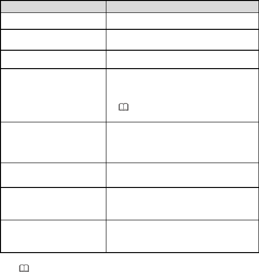
Mounting a GPON terminal on the desk
The figure blow uses an HG8247H as an example to show the ONT that is horizontally placed on a desk.
NOTE
CAUTION
4
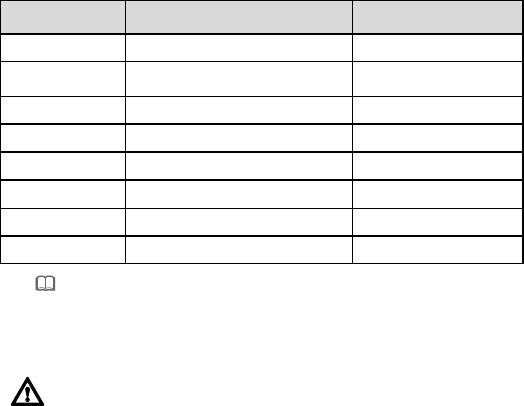
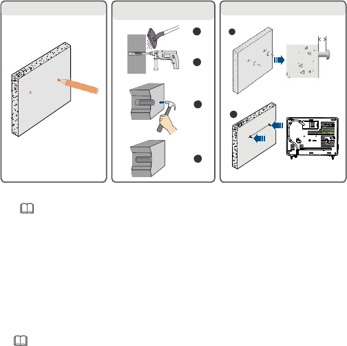
Mounting terminal vertically on the desk
(Only supported by some product models)
Install the foot-stand to the ONT according to the following figure, and place the ONT vertically on the
desk. The HN8245Q is used as an example here.
XG-PON terminals such as HN8245Q can not be horizontally placed on a desk or mounted
onto the wall.
NOTE
5
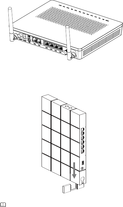
Mounting a GPON terminal onto the wall
(Only supported by some product models)
Step 1 Mark the positions of two holes used for mounting a GPON terminal, ensure that the
two holes have the same spacing as the two mounting holes.
Step 2 Select a proper drill according to the outer diameter of the screws. Use a hammer drill
to drill the marked positions on the wall. Then clean the wall and install two expansion
bolts.
Step 3 Use a screwdriver to fasten the screws into the expansion bolts, leaving the heads of
the screws 3 mm over the wall. Then install the GPON terminal to the screws.
This terminal is mainly placed horizontally on a desk. When it is mounted onto a wall, the
silkscreen of its indicator is reversed. If you have a special requirement on the silkscreen,
purchase another terminal.
Connecting Cables
Ports on GPON terminals of all types may be different. Therefore, connect cables based on the ports
that are actually supported by the device. If the external device is different from the device in the figure,
see the description for connections of the external device. This document lists connections of typical
devices.
2
1. Mark the installation positions. 2. Drill two holes and install
expansion bolts.
3. Install screws and the GPON terminal.
1
2
4
3
13 mm
NOTE
NOTE
1. The optical fiber connector connected to the optical port on the wall varies depending on
actual conditions.
2. To ensure normal use of fibers, make sure that the fiber bend radius is larger than 30 mm.
6
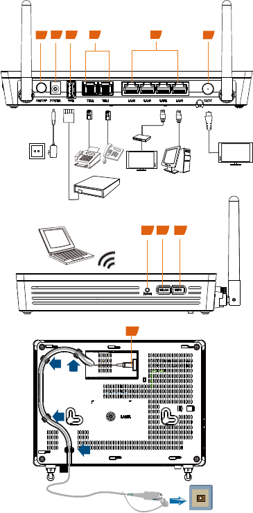
HG8247H
125
4
6
3
Fax machine
Phone
PC
TV set
IP STB
Power socket
USB storage device
TV set
Wi-Fi terminal 789
10
Optical port
7
1. Power switch
2. Power port
3. USB port
4. POTS port
5. Ethernet port
6. CATV port
7. Reset
8. WLAN switch
9. WPS switch
10. Optical port
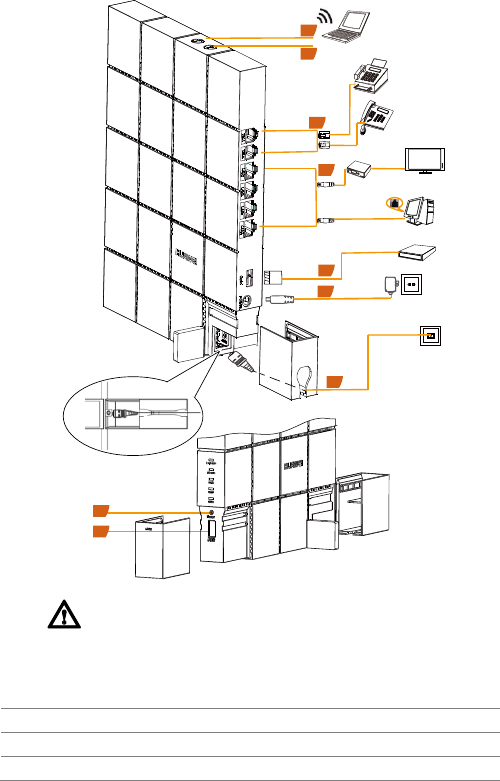
HN8255Ws
1. Optical port
2. Ethernet port
3. POTS port
4. USB port
5. Power port
6. WLAN switch
7. WPS switch
8. Light switch
9. Reset
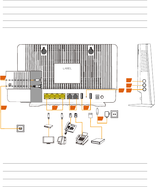
HN8245Q
Power On/OffUSB1USB2
Reset
LAN1 TEL2 TEL1LAN2LAN3LAN4
IP STB
TV set PC Fax machine
Phone
USB
storage
device
Power socket
Optical port
WLAN
1
2
2 3 4
5
6
7
89
8
After the optical fiber is connected to the optical port on the ONT, lead the fiber out of the
ONT through the hole on the fiber port cover, and then install the fiber port cover to the
ONT. If you do not lead the fiber out through the hole on the fiber port cover before you
install the cover, the fiber and ONT may be damaged.
1. POTS port
2. Ethernet port
3. USB port
4. Power port
5. Optical port
6. WLAN switch
7. WPS switch
8. RESET
6
4
4
6
Wi-Fi terminal
Fax machine
Phone
IP STB
TV set
PC
USB storage
device
Power socket
Optical port
6
7
1
2
3
4
5
3
8
CAUTION

9
Logging in to the Web Configuration Window
Step 1 Set the IP address of the PC in the same subnet as the management IP address of the
PON terminal.
You can find the default management IP address on the nameplate of the device.
Step 2 Enter the management IP address of the PON terminal in the address bar of Internet
Explorer and press Enter.
The login window is displayed.
Step 3 In the login window, select your preferred language, enter the user name and password
(printed on the nameplate of the device.), and click Login. After the password is
authenticated, the web configuration window is displayed.
Configuring Wi-Fi Parameters
Step 1 Choose the WLAN tab and choose WLAN Basic Configuration.
HN8245Q is different from GPON terminal, Choose the Advanced Configuration > WLAN
tab and choose 2.4G Basic Network Settings.
In the pane, select the Enable WLAN option box. In the dialog box that is displayed, set the
basic Wi-Fi parameters, including the SSID, authentication mode, and encryption mode. For
example:
Step 3 Click Apply.
ONT supporting Wi-Fi (such as HG8247H), a wireless network coverage is subject to the
number, thickness, and positions of walls, materials, ceilings, or other objects that radio
signals traverse. Besides, material type and background radio frequency (RF) noise also
affect the coverage of a wireless network. You can maximize the coverage of a wireless
network using the following methods:
NOTE
NOTE
NOTE
NOTE
Shipped from different manufacture batches, the nameplates of some devices do not have
the IP address, user name, and password printed. In such a case, log in to the device
using 192.168.100.1 (or 192.168.1.1), root (user name), and admin (password).
If you do not perform any operations after logging in to the system for five minutes, you will
exit the system and the system automatically returns to the login interface.
The system will be locked if you input incorrect user name and password three
consecutive times. One minute later, it will be unlocked.
Change the initial password after logging in to the web page.
SSID Name: WirelessNet (the name of a wireless network searched by the Wi-Fi
terminal)
Authentication Mode: WPA Pre-Shared Key
Encryption Mode: TKIP
WPA PreSharedKey: Password (the authentication password for the Wi-Fi terminal
to access a wireless network).

10
1. Decrease the number of walls and ceilings between HG8247H and other network
devices.
Each wall or ceiling reduces the coverage of a wireless network by one to 30 meters.
Install HG8247H at a proper place to avoid walls or ceilings whenever possible.
2. Observe the straight line rule when installing network devices.
The distance for which signals have to traverse at a 45° corner of two 0.5 meter-thick
walls reaches approximately one meter. To better receive signals, devices should be
installed at places where signals can directly traverse walls or ceilings.
3. Note the impact of building materials on the wireless network coverage.
A metal door or aluminum wall may limit the coverage of a wireless network. Install
access points, wireless routers, and computers, so signals can traverse walls or open
passageways. Materials and objects such as FRP products, metal products, insulative
walls, filing cabinets, bricks, and concrete weaken radio signals.
4. When connecting ONT (such as HG8247H) to a wireless network, keep it far from
the following devices:
5. In order to avoid the possibility of exceeding the Europe radio frequency
exposure limits, human proximity to the equipment shall not be less than 20 cm.
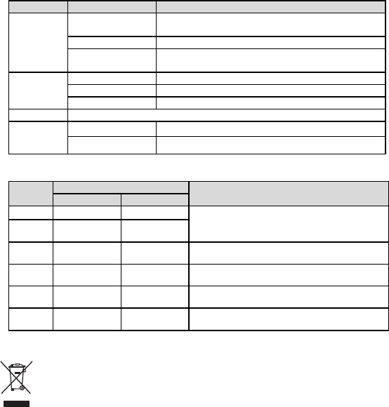
Indicator Description
Table 1-1 Indicator status description 1
Indicator
Status
Description
CATV
Always on
The CATV function is enabled and CATV signals are
received.
Off
The CATV function is disabled or CATV signals are not
received.
WPS
Steady on
The WPS function is enabled.
Blinking
A Wi-Fi terminal is accessing the system.
Off
The WPS function is disabled.
WLAN
Steady on
The WLAN function is enabled.
Blinking
Data is being transmitted on the WLAN port.
Off
The WLAN function is disabled.
USB
Steady on
The USB port is connected and is working in the host
mode, but no data is transmitted.
Blinks twice a
second
Data is being transmitted on the USB port.
Off
The system is not powered on or the USB port is not
connected.
Electronic devices or components that produce RF noises (keep a distance of more than 2
meters between such a device and HG8247H.)
2.4 GHz wireless mobile phones or X-10 devices (such as microwave ovens, home
security systems, blue-tooth devices, and refrigerators) that greatly weaken or even
eliminate radio signals. Even if a 2.4 GHz wireless mobile phone is not connected to a
wireless network, the phone base still sends signals that interfere the wireless network.
11
Indicator
Status
Description
TEL1–
TEL2
Steady on
The terminal is registered with the softswitch but no
service flows are transmitted.
Blinking
Service flows are transmitted.
Off
The terminal is not powered on or fails to be registered to
the softswitch.
LAN1–
LAN4/
10G LAN
Steady on
The Ethernet connection is in the normal state.
Blinking
Data is being transmitted on the Ethernet port.
Off
The Ethernet connection is not set up.
LOS/PON
See Table 1-2.
POWER
Steady green
The terminal is powered on.
Off
The power supply is cut off.
Table 1-2 Indicator status description 2
Status
No.
Status
Description
PON
LOS
1
Off
Off
The PON terminal is prohibited by the upper-layer
device or blinks abnormally, contact the service
provider for help.
2
Blinks twice a
second
Blinks twice a
second
3
Blinks twice a
second
Off
The PON terminal attempts to set up a
connection with its upper-layer device.
4
Steady on
Off
A connection is set up between the PON terminal
and its upper-layer device.
5
Off
Blinks once
two seconds
The PON terminal is not connected to optical
fibers or does not receive optical signals.
6
Blinks once
two seconds
Blinks once
two seconds
The hardware is faulty.
Disposal and recycling information
The crossed-out wheeled-bin symbol on your product, battery, literature or packaging
reminds you that all electronic products and batteries must be taken to separate waste
collection points at the end of their working lives; they must not be disposed of in the
normal waste stream with household garbage. It is the responsibility of the user to dispose
of the equipment using a designated collection point or service for separate recycling of
waste electrical and electronic equipment (WEEE) and batteries according to local laws.
Proper collection and recycling of your equipment helps ensure electrical and electronic equipment (EEE)
waste is recycled in a manner that conserves valuable materials and protects human health and the
environment, improper handling, accidental breakage, damage, and/or improper recycling at the end of
its life may be harmful for health and environment. For more information about where and how to drop off
your EEE waste, please contact your local authorities, retailer or household waste disposal service or
visit the website www.huawei.com/en/product-certification.
Reduction of hazardous substances
This device and any electrical accessories are compliant with local applicable rules on the restriction of
the use of certain hazardous substances in electrical and electronic equipment, such as EU REACH,
RoHS and Batteries (where included) regulations, etc. For declarations of conformity about REACH and
RoHS, please visit our web site www.huawei.com/en/product-certification.

12
EU regulatory conformance#
Statement
Hereby, Huawei Technologies Co., Ltd. declares that this device is in compliance with the essential
requirements and other relevant provisions of Directive 2014/53/EU.
The most recent and valid version of the DoC (Declaration of Conformity) can be viewed at
www.huawei.com/en/product-certification.
This device may be operated in all member states of the EU.
Observe national and local regulations where the device is used.
This device may be restricted for use, depending on the local network.
Restrictions in the 5 GHz band:
According to Article 10 (10) of Directive 2014/53/EU, the packaging shows that this radio equipment will
be subject to some restrictions when placed on the market in Belgium (BE), Bulgaria (BG), the Czech
Republic (CZ), Denmark (DK), Germany (DE), Estonia (EE), Ireland (IE), Greece (EL), Spain (ES),
France (FR), Croatia (HR), Italy (IT), Cyprus (CY), Latvia (LV), Lithuania (LT), Luxembourg (LU),
Hungary (HU), Malta (MT), Netherlands (NL), Austria (AT), Poland (PL), Portugal (PT), Romania (RO),
Slovenia (SI), Slovakia (SK), Finland (FI), Sweden (SE), the United Kingdom (UK), Turkey (TR), Norway
(NO), Switzerland (CH), Iceland (IS), and Liechtenstein (LI).
The WLAN function for this device is restricted to indoor use only when operating in the 5150 to 5350
MHz frequency range.
1. Ignore this section if the product does not support Wi-Fi access.
2. Actual 2.4 GHz or 5 GHz products (supporting Wi-Fi) prevail.
ErP product information
Hereby, Huawei Technologies Co., Ltd. declares that the product meets the directive 2009/125/EC and
its implementation regulation (EC) NO 1275/2008 amended by (EC) 278/2009, (EC) 642/2009, (EU)
617/2013, (EU) 801/2013, and its implementation regulation (EC) NO 278/2009.
If all wired network ports are connected and all wireless network ports are activated, the power
consumption of the product in networked standby is less than 20 W.
For the product information displayed on the manufacturers' freely accessible websites required by (EU)
No 801/2013, please visit www.huawei.com/en/product-certification.
To enable or disable the wireless network function:
Press the WLAN button on the side panel of the product. (Ignore this method if the product has no
such a button or this button is invalid.)
Log in to the web page, choose Advanced Configuration > WLAN > Basic Network Settings >
Enable WLAN. (Different products may have different configuration pages.)
Frequency bands and power
(a) Frequency bands in which the radio equipment operates: Some bands may not be available in all
countries or all areas. Please contact the local carrier for more details.
(b) Maximum radio-frequency power transmitted in the frequency bands in which the radio equipment
operates: The maximum power for all bands is less than the highest limit value specified in the related
Harmonized Standard.
The frequency bands and transmitting power (radiated and/or conducted) nominal limits applicable to
this radio equipment are as follows:
Wi-Fi 2.4 GHz: < 20 dBm
Wi-Fi 5 GHz: 5150-5350 MHz, < 23 dBm; 5470-5725 MHz, < 30 dBm
Frequencies of products are determined based on functions supported.
Accessories and software information
It is recommended that the following accessory should be used: adapter.
CAUTION
NOTE

13
Different product packages may deliver different adapter lists. The actual delivered
accessory list prevails.
The software version is in the format of VXXXRXXXCXX (for example, V300R015C10). For the specific
version, see the label on the giftbox.
Software updates will be released by the manufacturer to fix bugs or enhance functions after the product
has been released. All software versions released by the manufacturer have been verified and are still
compliant with the related rules.
For more information about the software, see web pages of products.
All RF parameters (for example, frequency range and output power) are not accessible to the user, and
cannot be changed by the user.
Contents marked with # is applicable to EU countries.
FCC Statement
This equipment has been tested and found to comply with the limits for a Class B digital device, pursuant
to part 15 of the FCC Rules. These limits are designed to provide reasonable protection against harmful
interference in a residential installation. This equipment generates, uses and can radiate radio frequency
energy and, if not installed and used in accordance with the instructions, may cause harmful interference
to radio communications. However, there is no guarantee that interference will not occur in a particular
installation. If this equipment does cause harmful interference to radio or television reception, which can
be determined by turning the equipment off and on, the user is encouraged to try to correct the
interference by one or more of the following measures:
-- Reorient or relocate the receiving antenna.
-- Increase the separation between the equipment and receiver.
-- Connect the equipment into an outlet on a circuit different from that to which the receiver is connected.
-- Consult the dealer or an experienced radio/TV technician for help.
FCC Radiation Exposure Statement
This device complies with FCC radiation exposure limits set forth for an uncontrolled environment and it
also complies with Part 15 of the FCC RF Rules. This equipment must be installed and operated in
accordance with provided instructions and the antenna(s) used for this transmitter must be installed to
provide a separation distance of at least 20cm from all persons and must not be co-located or operating
in conjunction with any other antenna or transmitter. End-users and installers must be provide with
antenna installationinstructions and consider removing the no-collocation statement.This device
complies with Part 15 of the FCC Rules. Operation is subject to the following
two conditions: (1) this device may not cause harmful interference, and (2) this device must accept any
interference received, including interference that may cause undesired
operation.
Caution
Any changes or modifications not expressly approved by the party responsible for compliance could void
the user's authority to operate the equipment.
NOTE
1. Contents marked with * are applicable to America.
2. Contents marked with # and CE are applicable to EU countries.
NOTE
NOTE
14
RF Exposure
This equipment complies with FCC radiation exposure limits set forth for an
uncontrolled environment. This equipment should be installed and operated withminimum
distance 20cm between the radiator & your body.
FAQs
The LOS indicator blinks.
If the LOS indicator blinks once two seconds, check whether the pigtail fiber is properly
connected and the connector is clean.
If the GPON terminal blinks twice a second, contact the service provider for help.
The PON indicator is off.
Check whether the OPTICAL port and optical fiber is properly connected.
The GPON terminal fails to register with the upper-layer device. Contact the service
provider for help.
The phone does not ring upon an incoming call but communication is in normal state
when the phone is in off-hook state.
The GPON terminal provides a maximum of 60 V AC ringing current voltage. Check
whether the ringing current voltage of the phone is higher than 60 V AC. If it is higher than
60 V AC, replace it with another phone.
How can I restore factory defaults?
Press Reset by using a needle-type object for longer than 10s to restore factory defaults
and reset the GPON terminal. If the indicator is off and then is lit, the system restarts
successfully.
Copyright © Huawei Technologies Co., Ltd. 2017. All
rights reserved.
No part of this document may be reproduced or transmitted in any form or by any
means without prior written consent of Huawei Technologies Co., Ltd.
Issue: 11 (2017-04-22)
BOM number: 31505718
PASS
Qualification Card
Warranty Card
Thank you for choosing Huawei Technologies Co., Ltd. To get better services,
please read this warranty card carefully, fill in the required information, and
preserve this card in good condition.
User Information
Personal or
Company's full name:
Address/Postal Code:
T
elephone:
Email:
Product
T
ype:
Product Serial Number:
Purchase Date:
In
voice Numbe
r:
Dealer's Name:
Dealer's Address:
Deale
r's
T
elephone
:
Preserve well. No reissue.
Dealer's Seal
Limited Warranty
Subject to the exclusions contained below, Huawei Technologies Co., Ltd. (Huawei
for short) warrants its access terminals ("Products") to be free from defects in
materials and workmanship under normal consumer usage for one year from
the date of purchase of the product ("Warranty period"). During the warranty
period, a Huawei authorized service partner shall remedy defects in materials and
workmanship free of charge.
Special Notice:
1. The warranty card shall be applicable only after being stamped by the dealer.
2. The warranty card must be preserved in good condition and free of any scratch or
alteration.
3. To claim such service for defects that are not included in the following exclusion
terms, the warranty card and the invoice that records that product serial number
shall be presented to a Huawei authorized service partner.
Exclusions:
In any of the following cases, the warranty card becomes unenforceable or
inapplicable without prior notice:
1. The defects are caused by improper handling in transportation and assembly.
2. The defects are caused by the fact that the product is dismantled or altered by
anyone that is not from a Huawei authorized service partner.
3. The defects are caused by the fact that the product is used in a harsh environment
that is not suitable for the operation of the product.
4. The defects are caused by any force majeure including but not limited to fire,
earthquake, lightning, and tsunami.
5. The defects are caused by the fact that the product is used or handled incorrectly,
roughly or not as instructed in the applicable User Guide.
6. The normal wear and tear, including but not limited to the normal wear and tear of
the shell and the power module, shall not be covered by the limited warranty.
7. The warranty card is altered or illegible, or the product serial number recorded on
the warranty card is inconsistent with the actual one imprinted or labeled on the
product.
In any case that is not covered by this limited warranty or should the warranty expire,
Huawei shall charge for the service(s) claimed for the products if the product is still
remediable. Huawei reserves all rights to interpret this limited warranty.
Huawei Technologies Co., Ltd.
Address: Huawei Industrial Base
Bantian, Longgang
Shenzhen 518129
People's Republic of China
Website: http://www.huawei.com