Huawei Technologies EGW1520A eSpace EGW1520 User Manual UserManual Part2
Huawei Technologies Co.,Ltd eSpace EGW1520 UserManual Part2
UserManual.wiki
>
Huawei Technologies
>
EGW1520A User Manual
>
UserManual_Part2.pdf
Contents
1.
QuickStartGuide.pdf
2.
Regulatory Compliance and Safety Manual eSpace EGW1520.pdf
3.
UserManual_Part1.pdf
4.
UserManual_Part2.pdf
5.
UserManual_Part3.pdf
UserManual_Part2.pdf
Navigation menu
Upload a User Manual
Namespaces
Wiki Guide
HTML
PDF
Info
Views
User Manual
Discussion / Help
Navigation
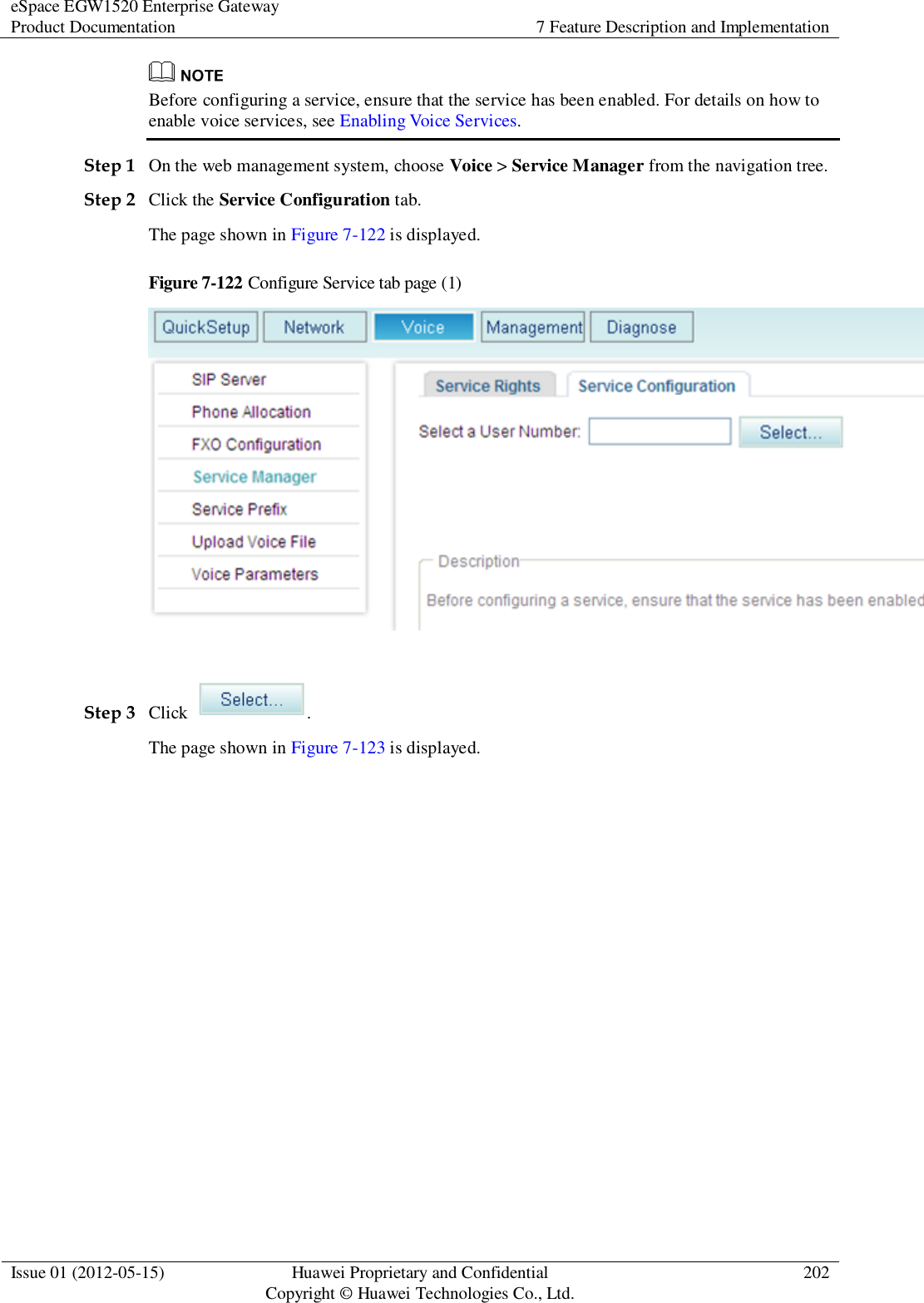
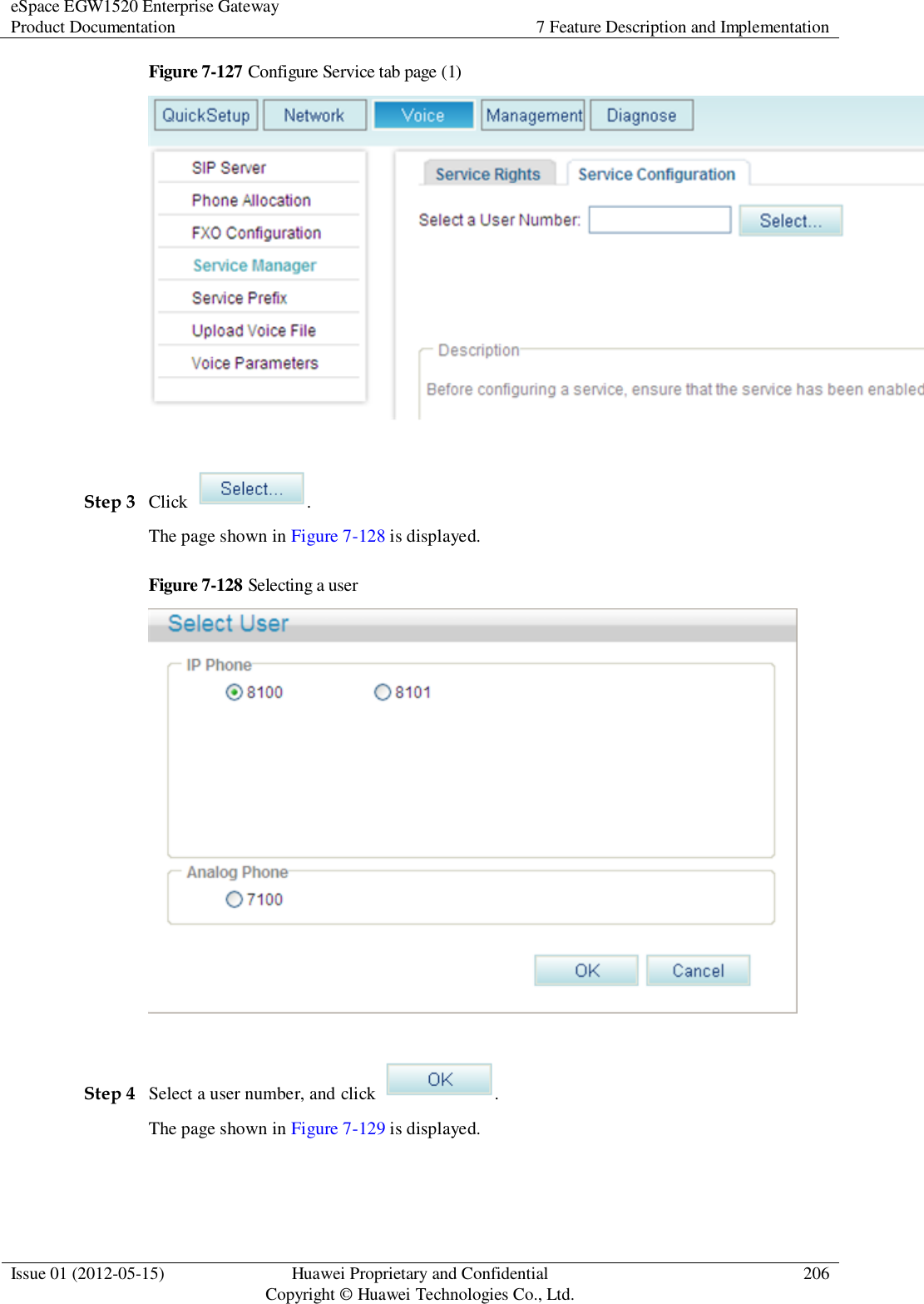
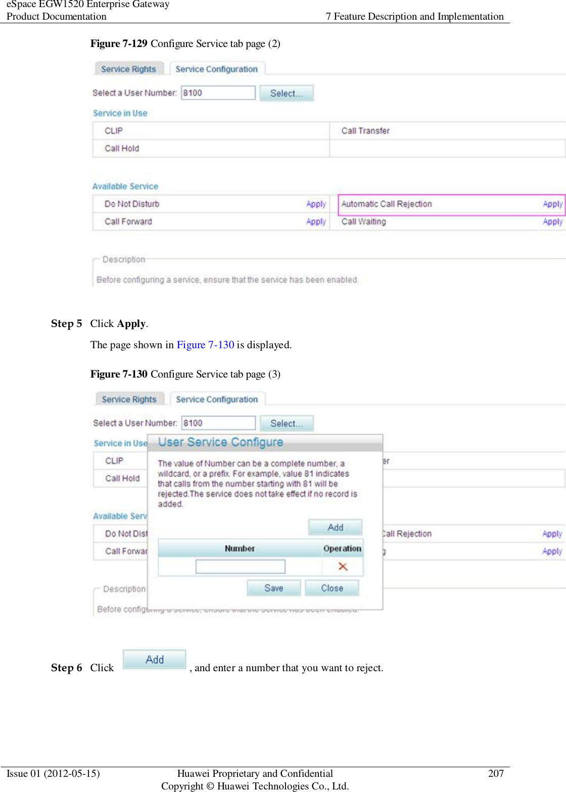
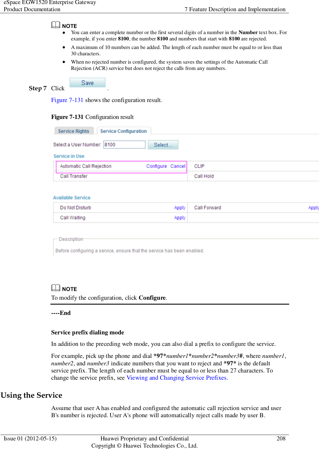
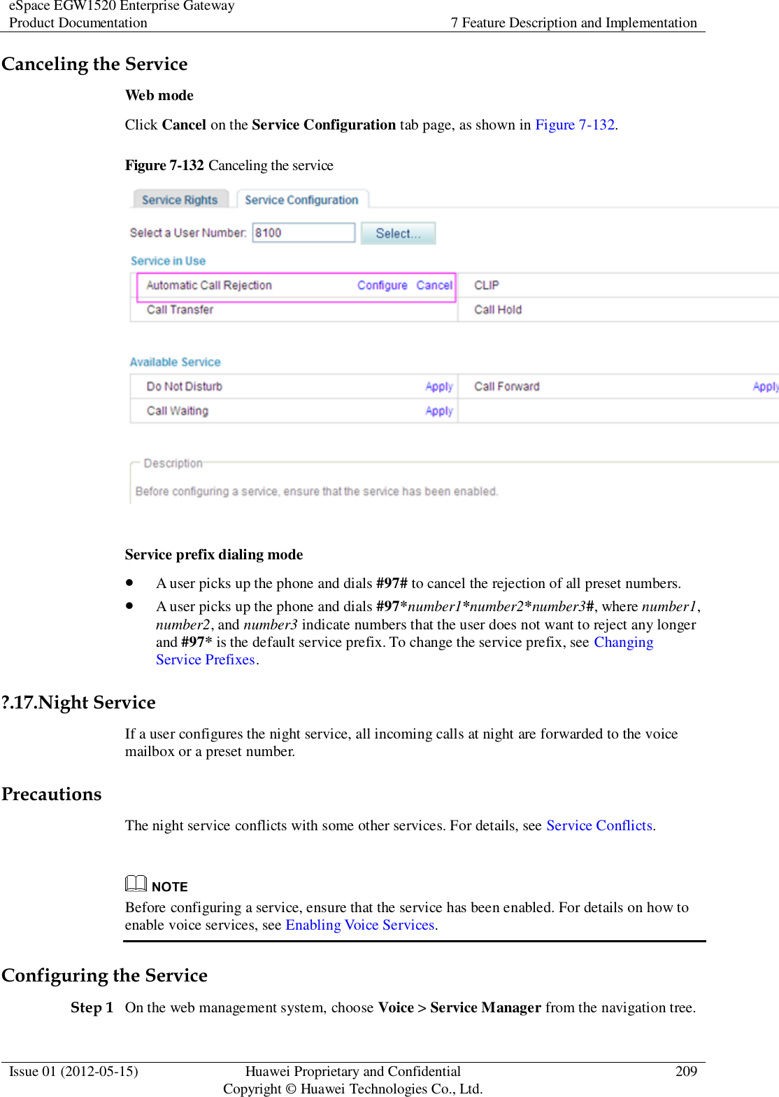
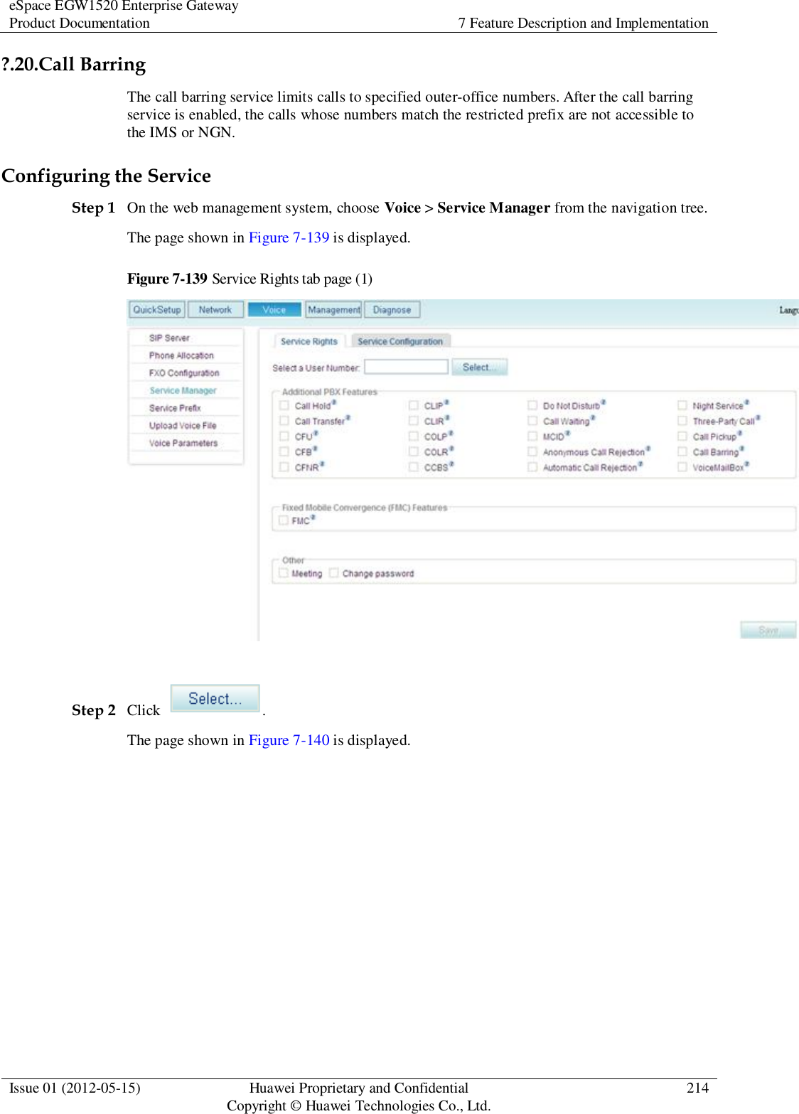
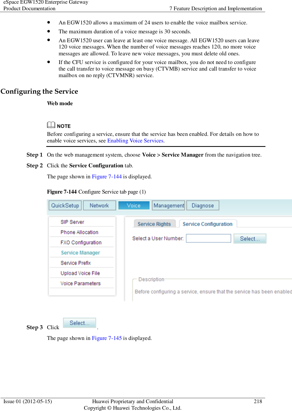
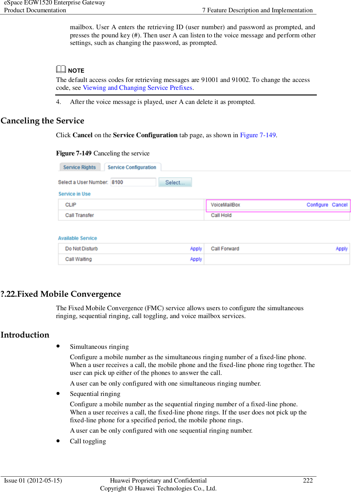
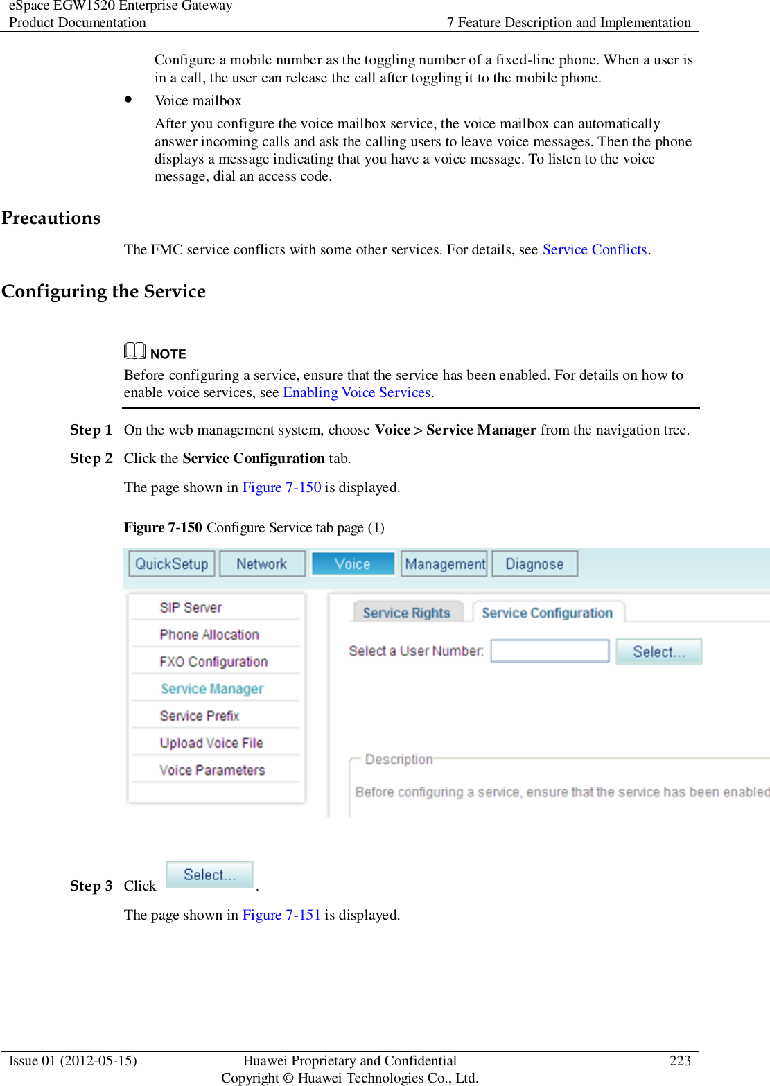
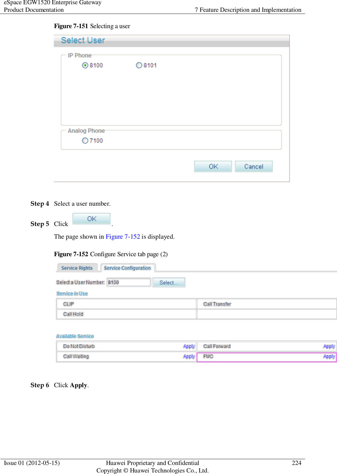
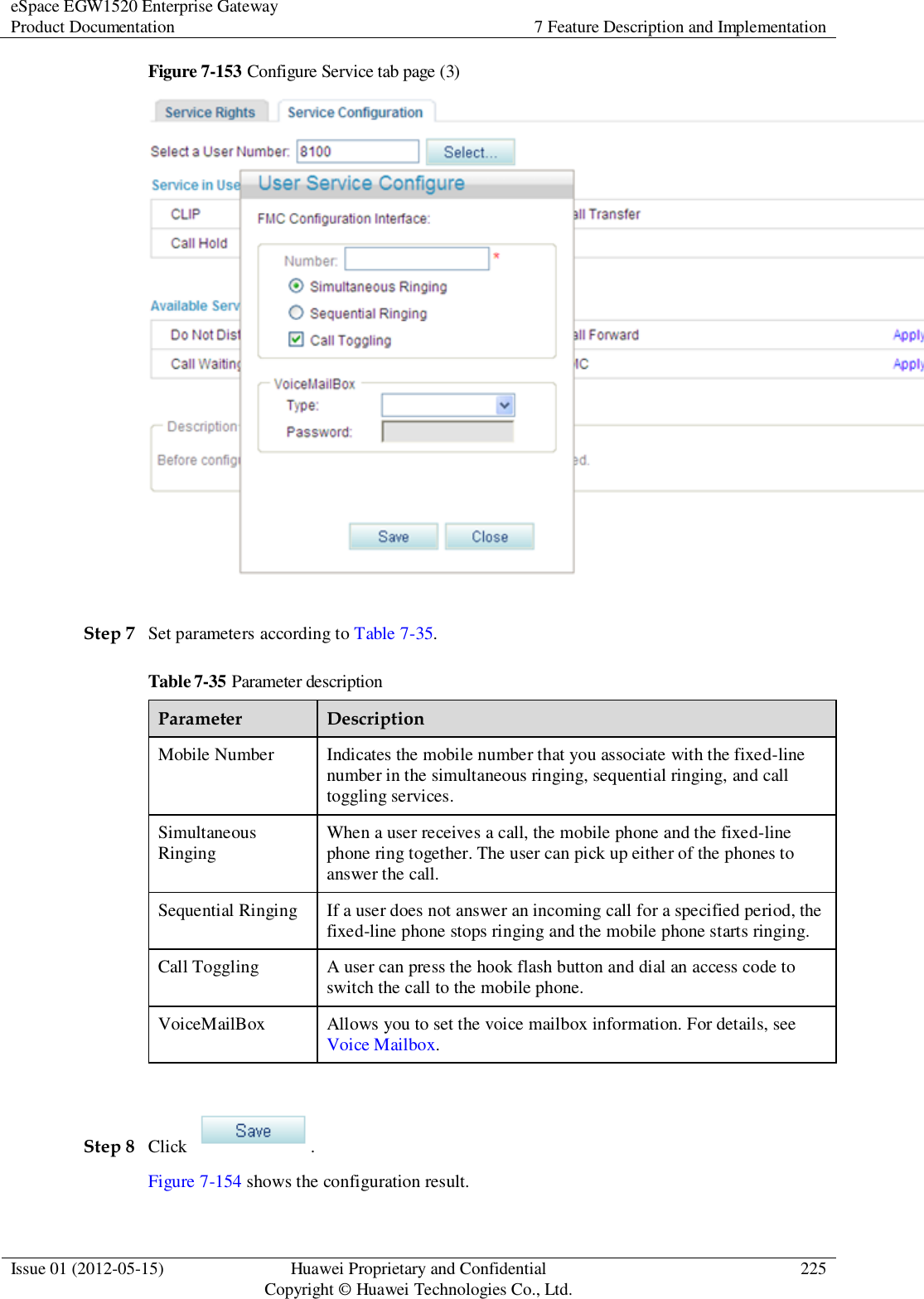
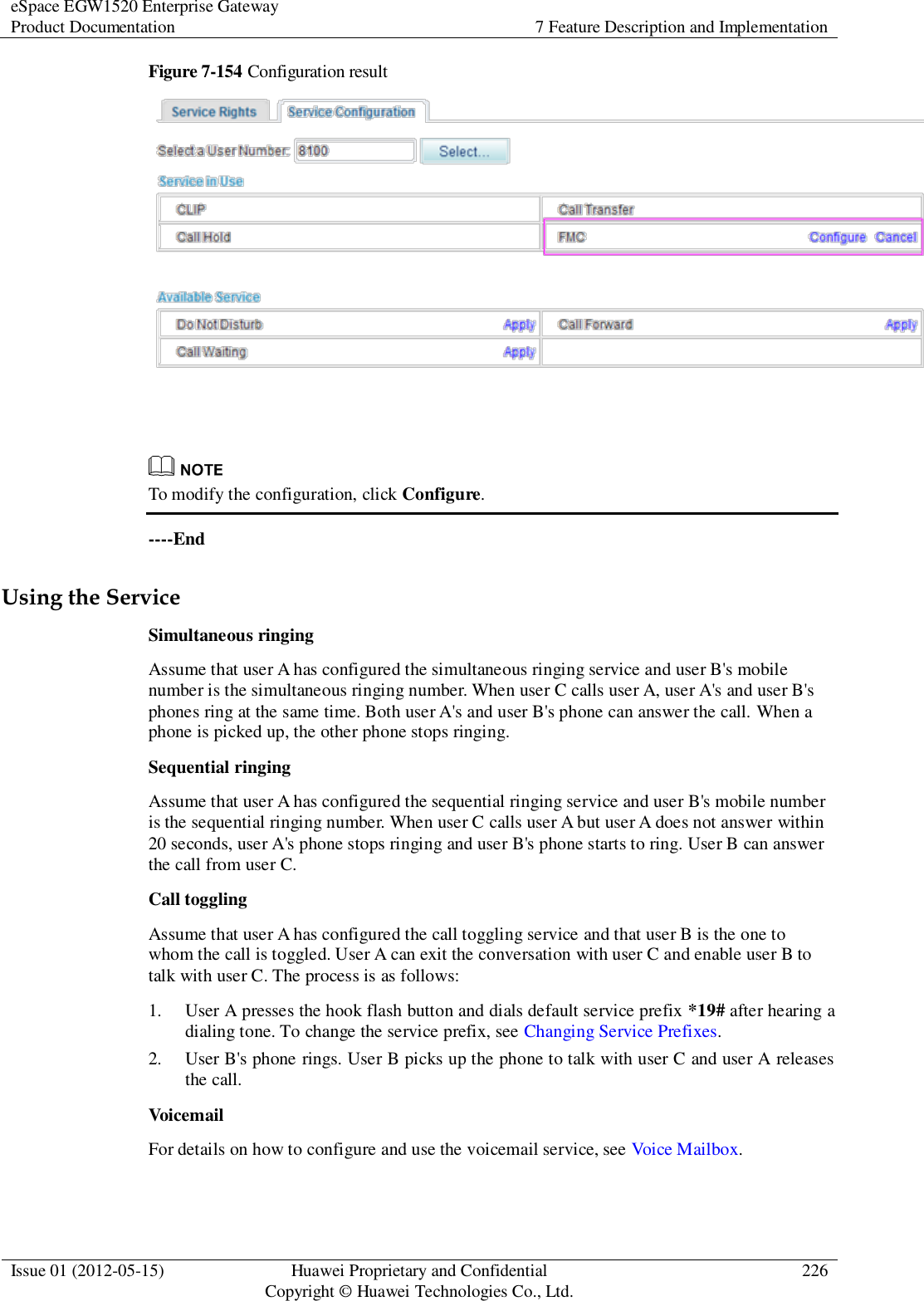
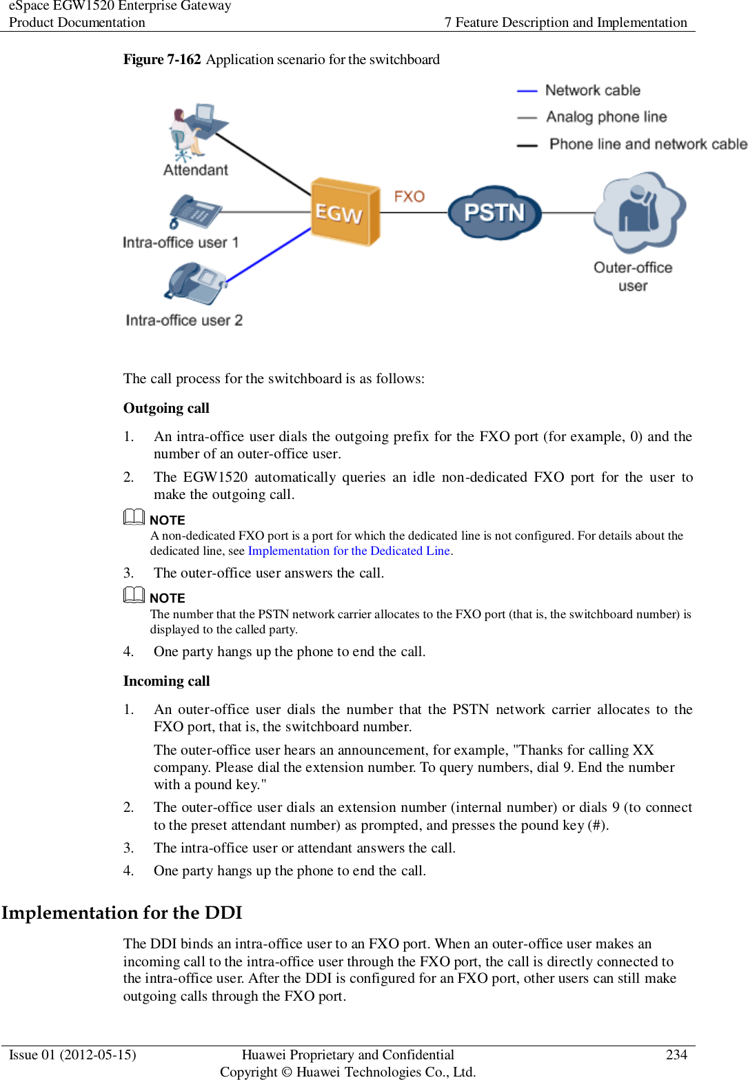
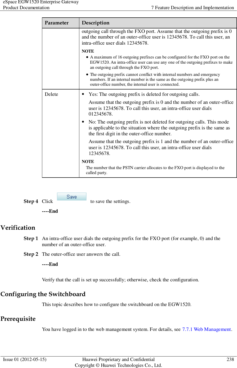
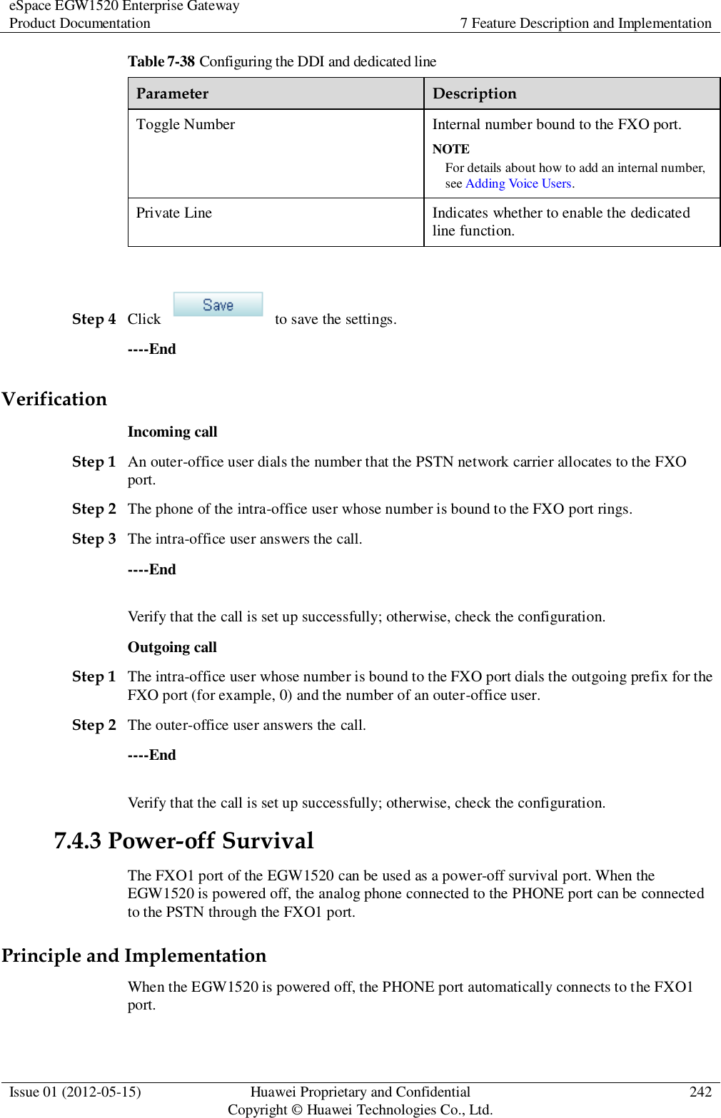
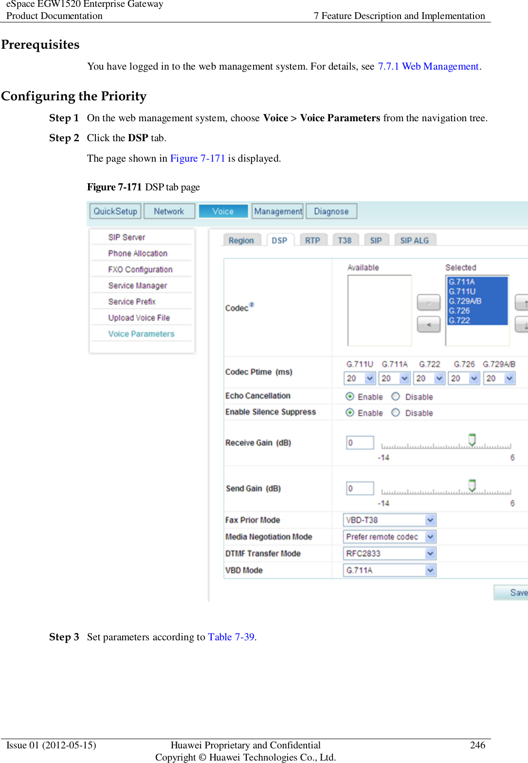
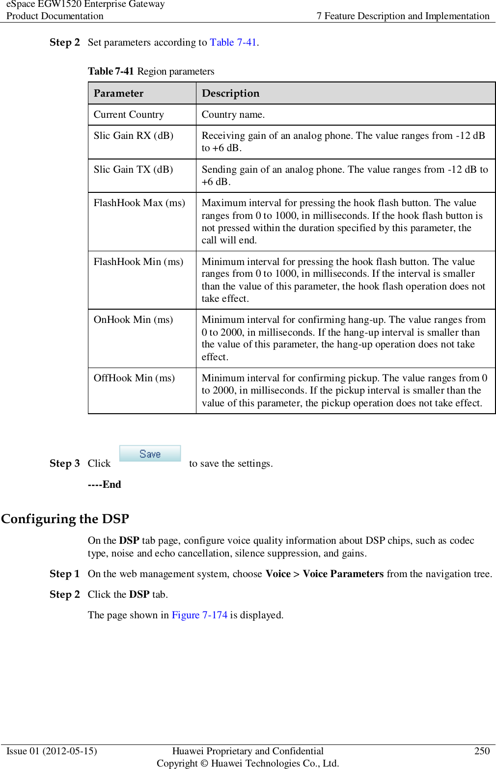
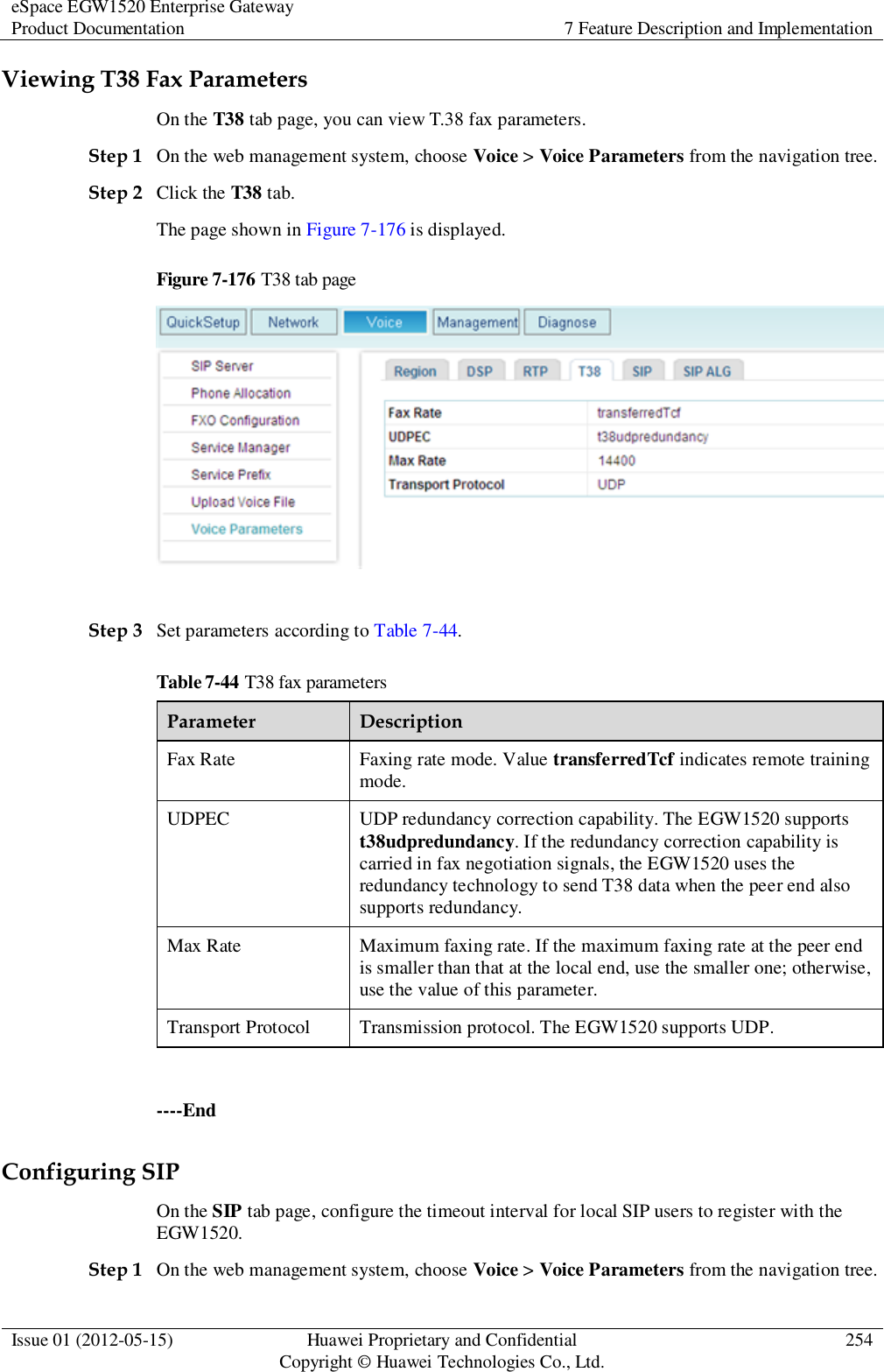
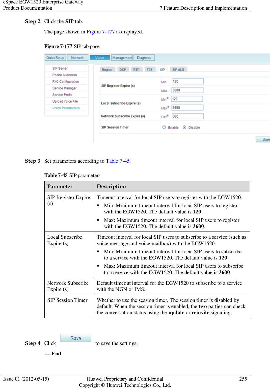
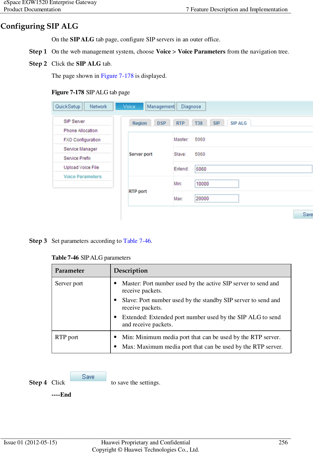
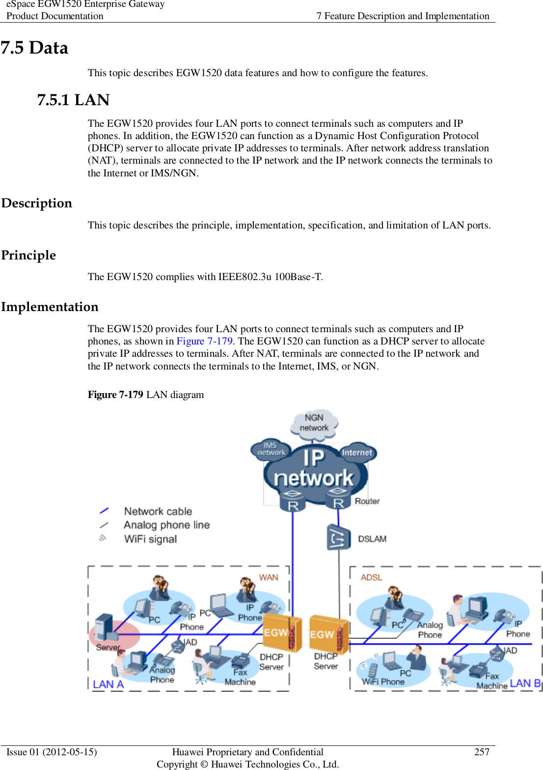
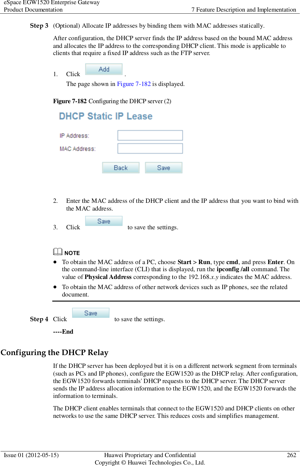
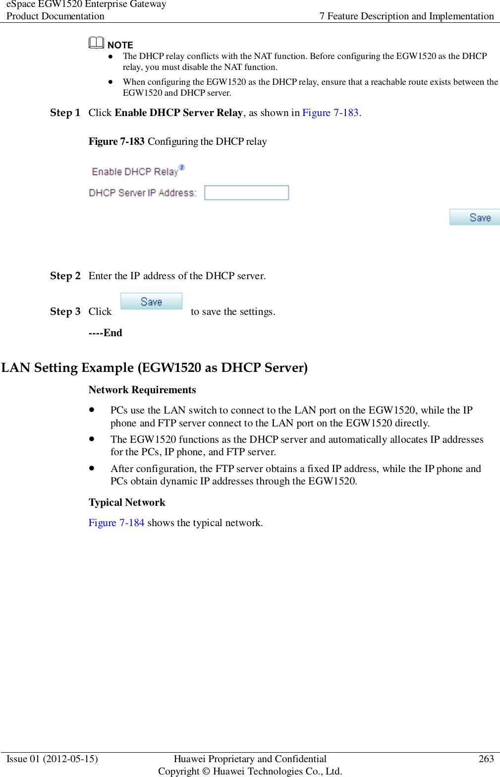
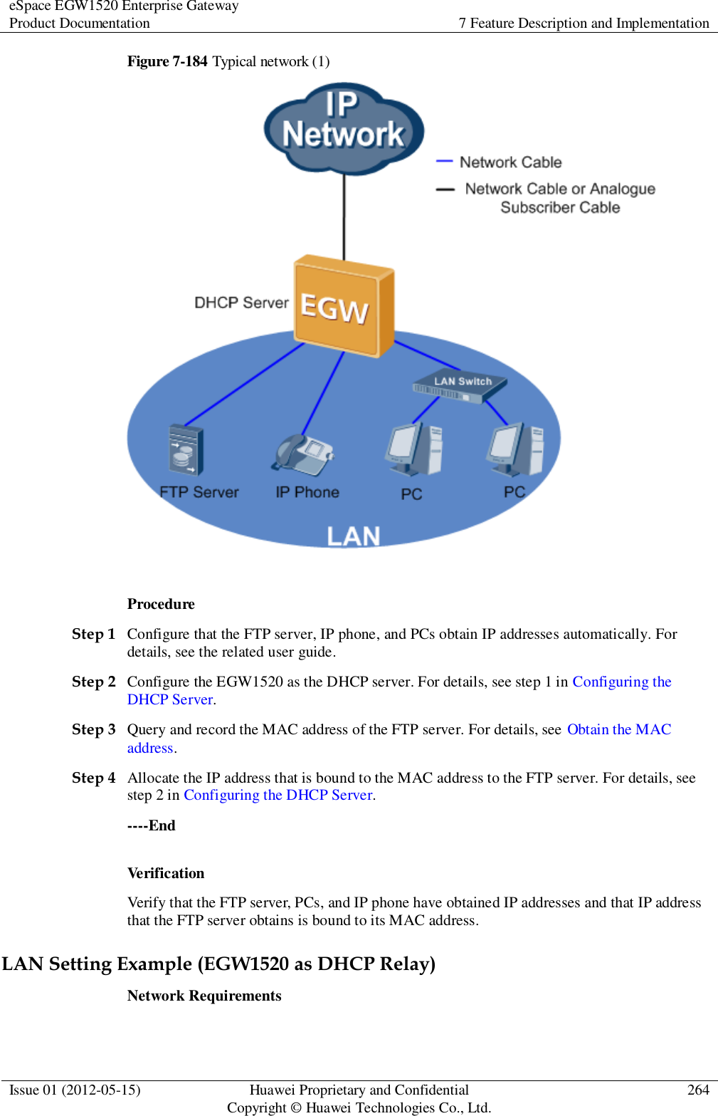
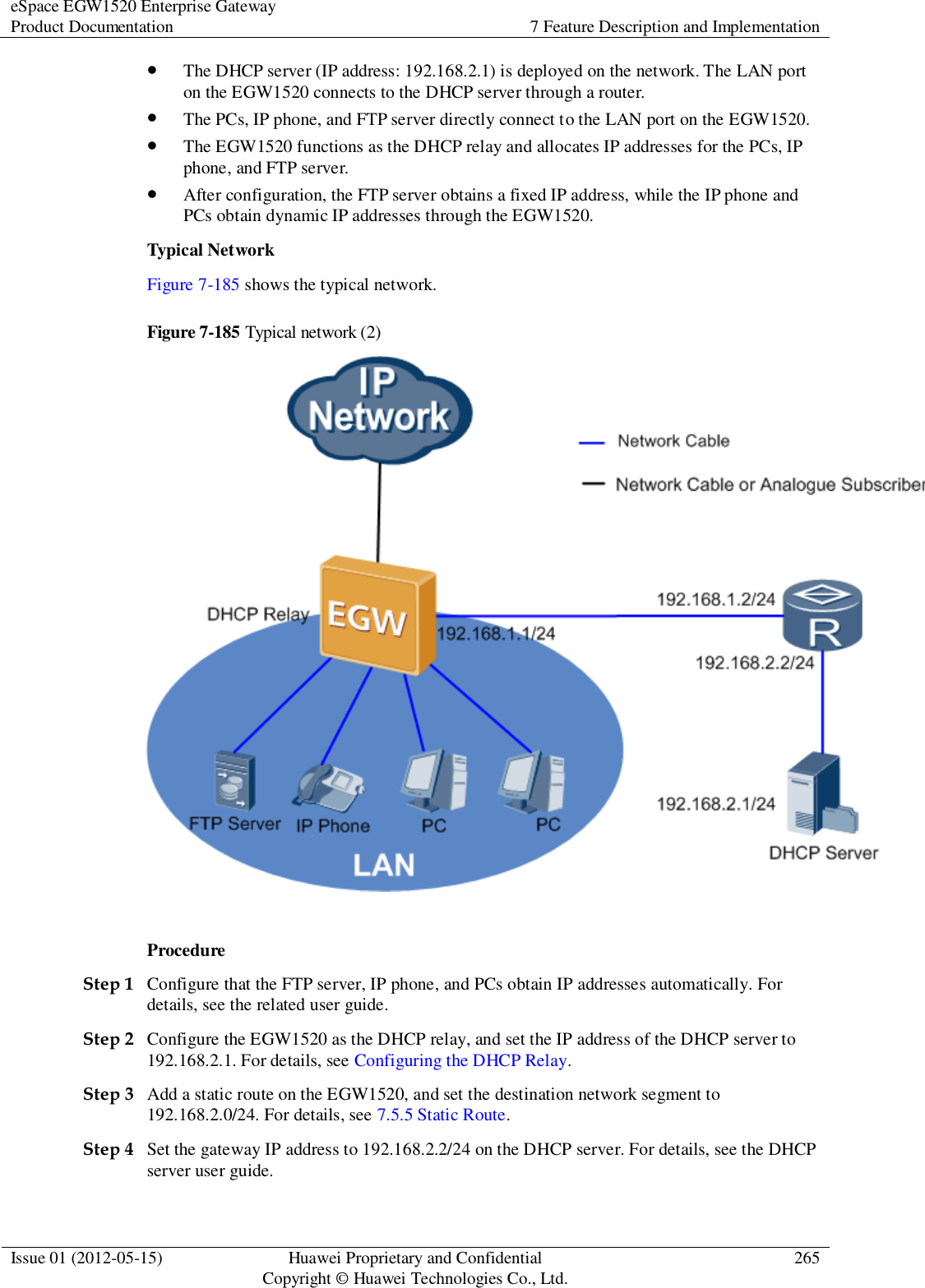
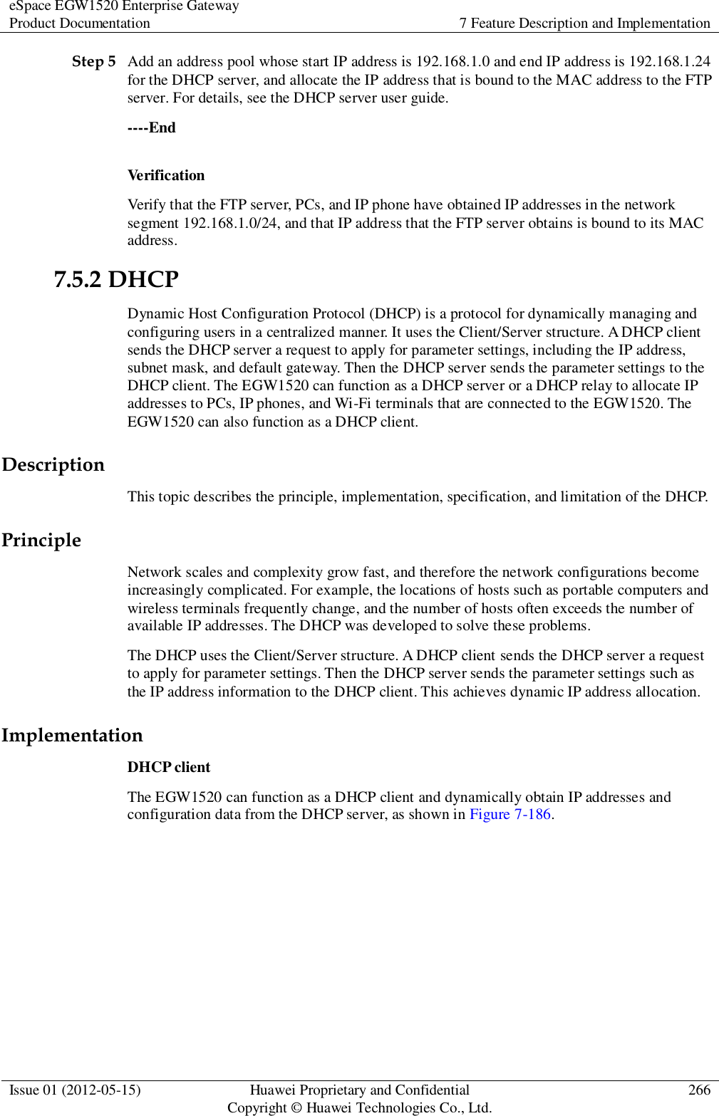
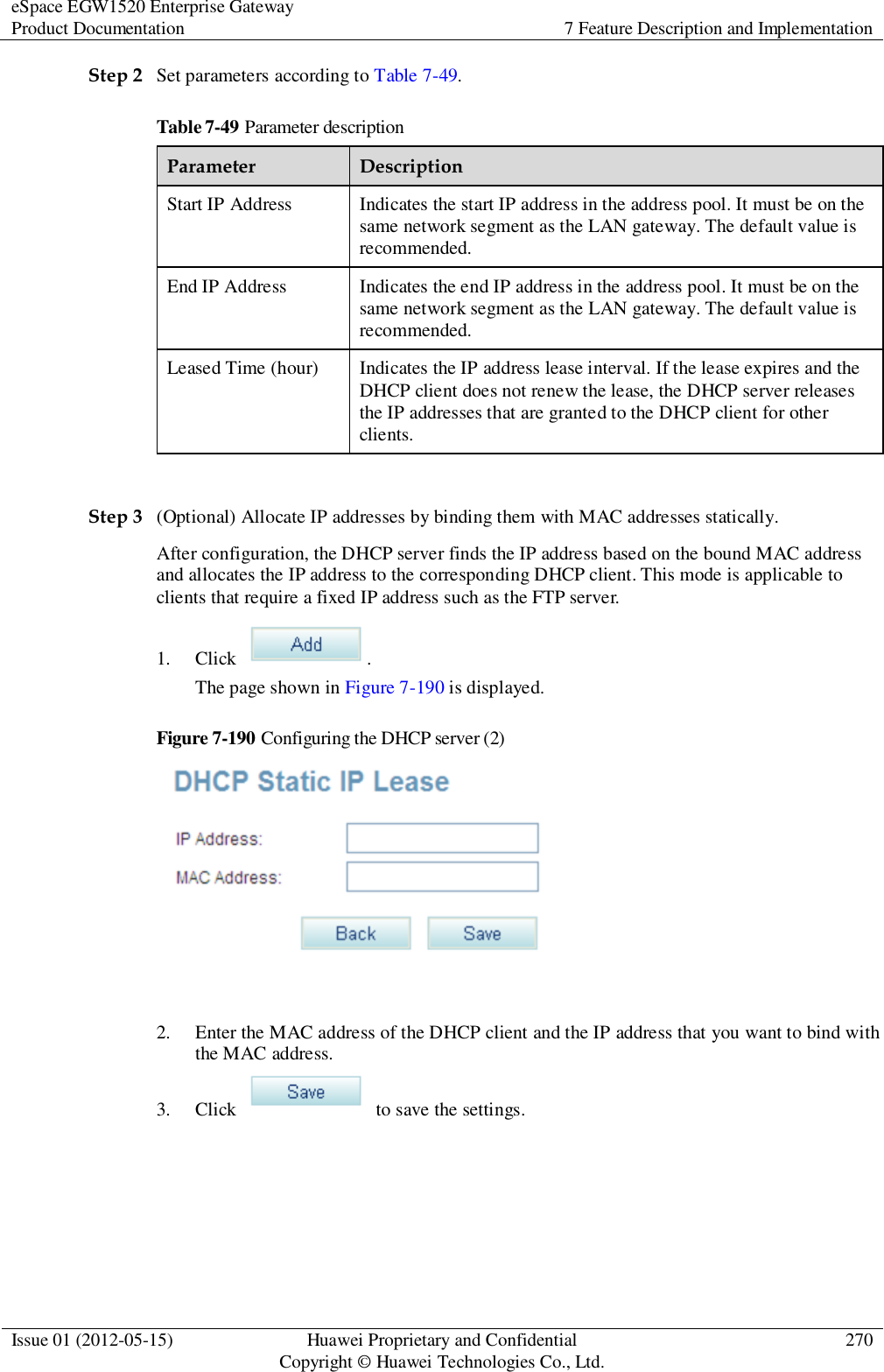
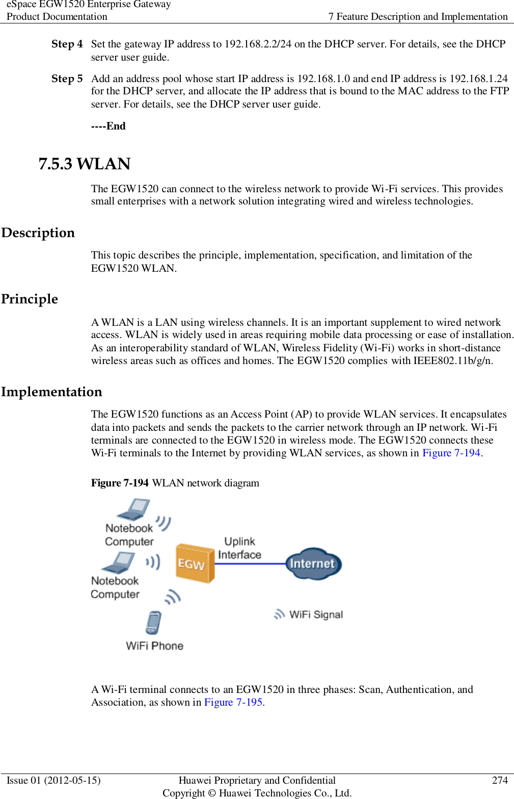
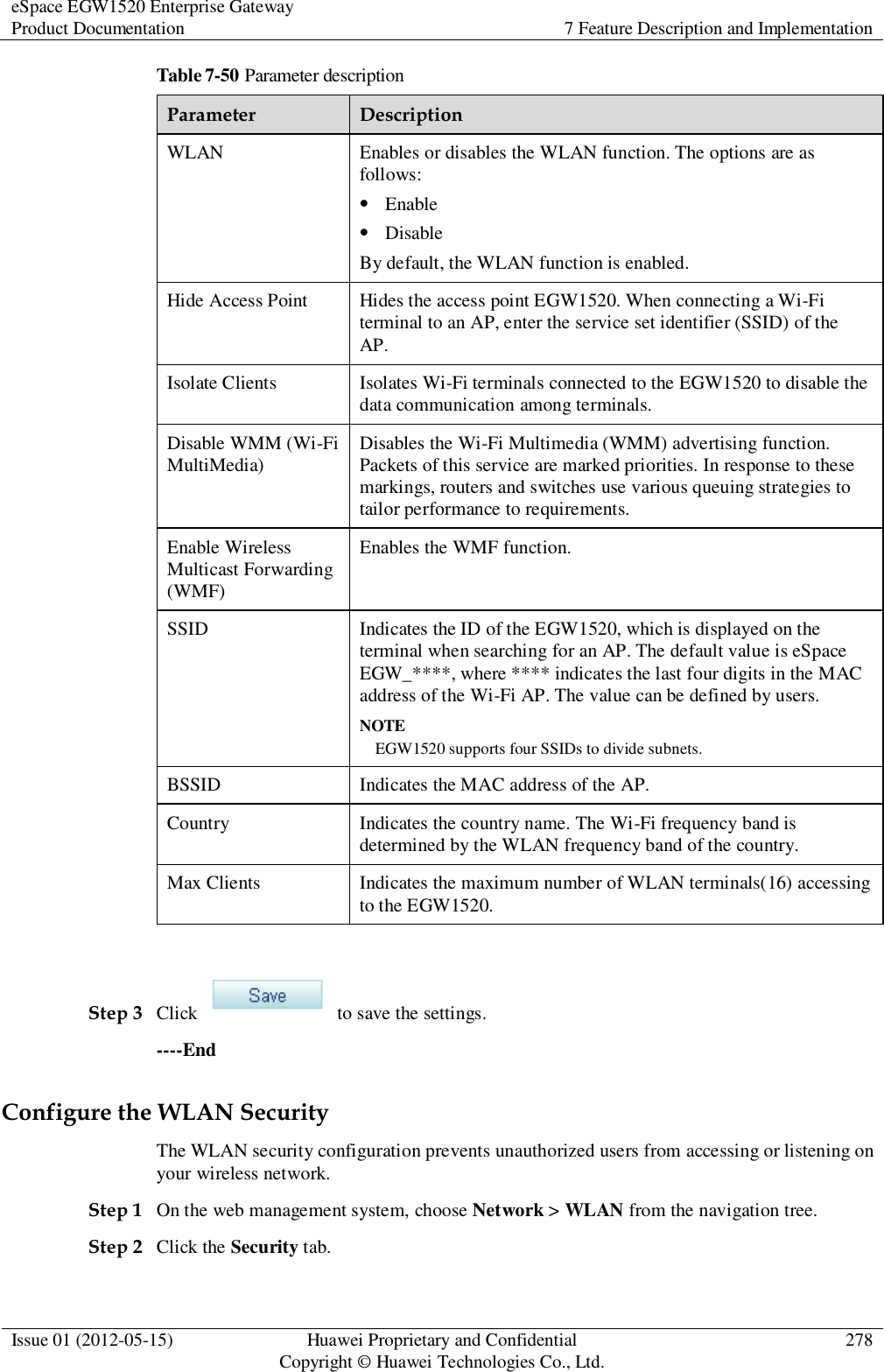
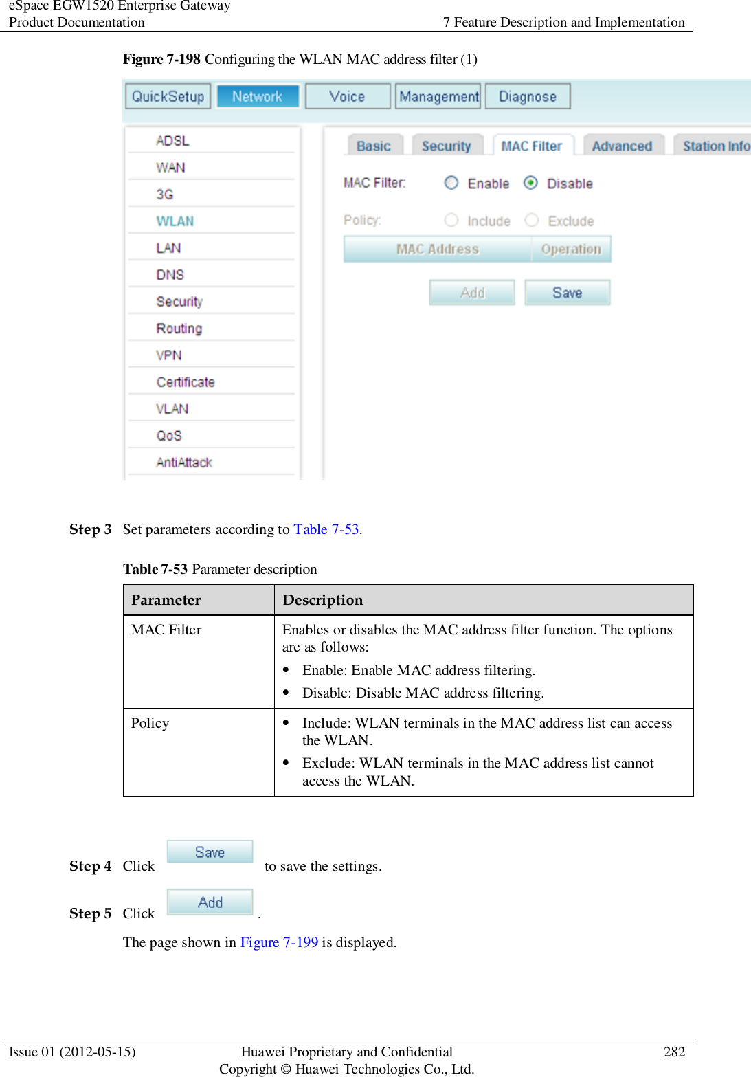
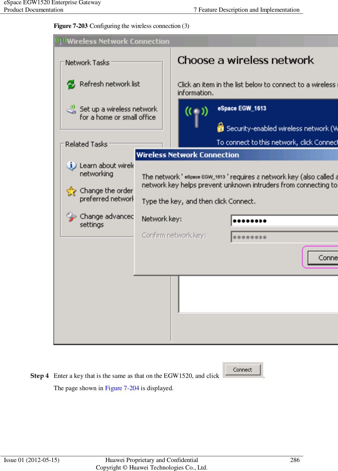
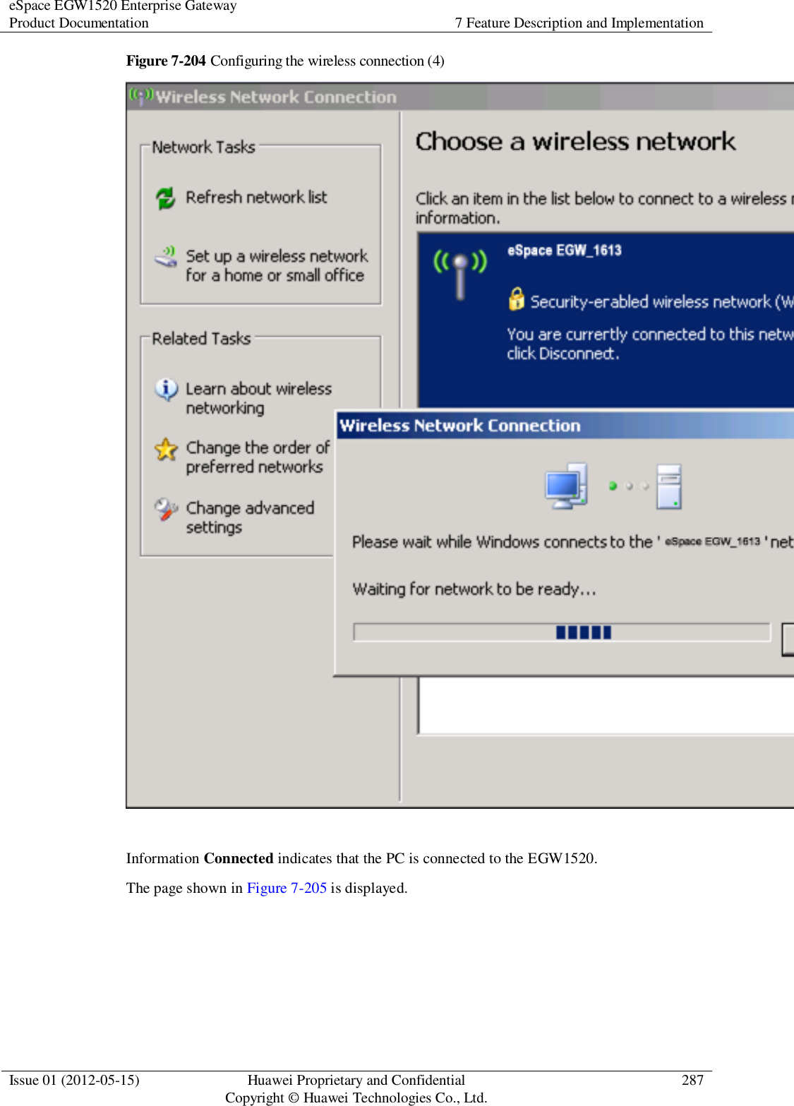
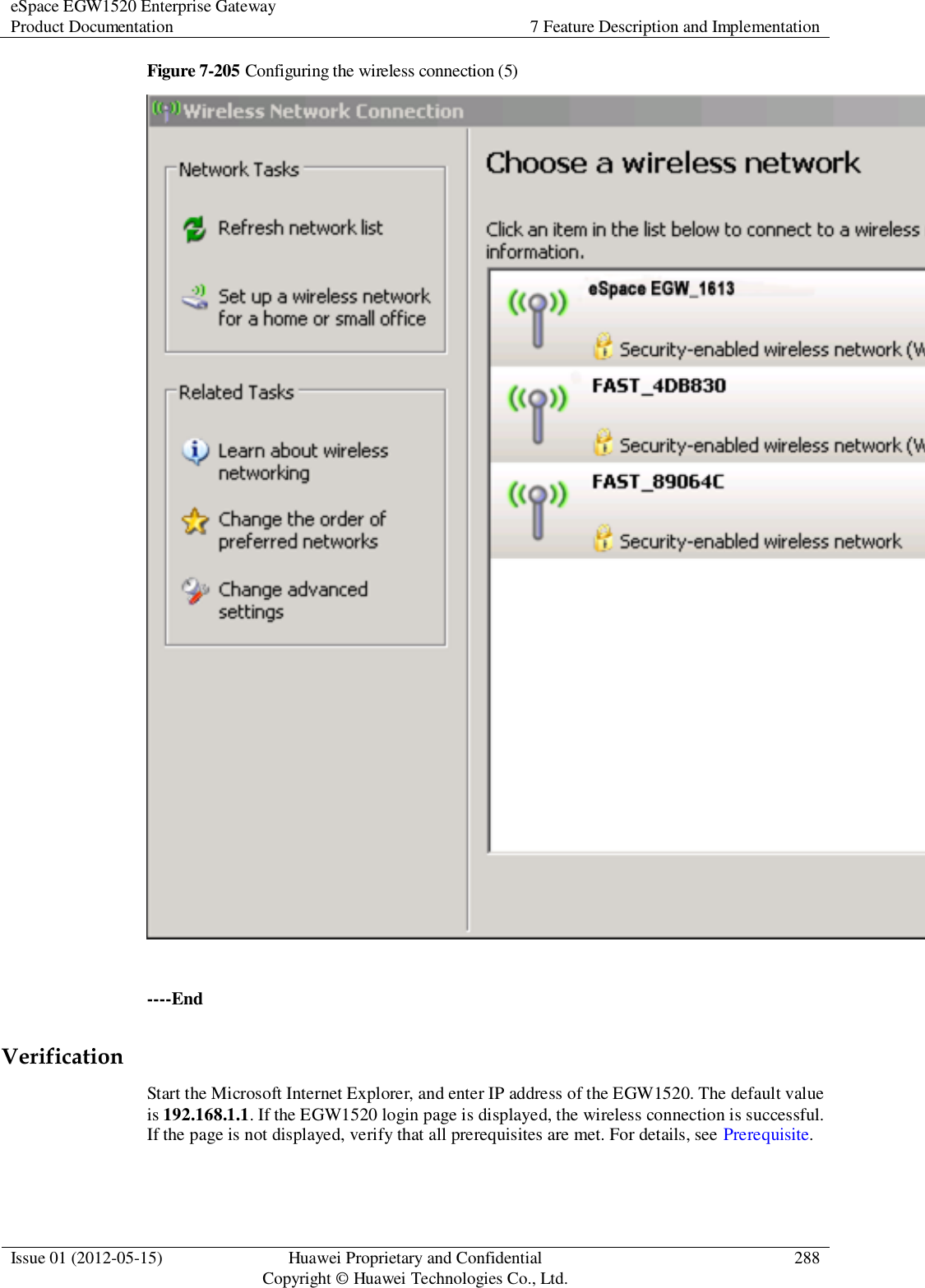
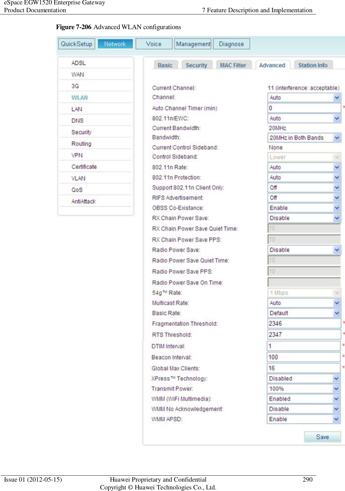
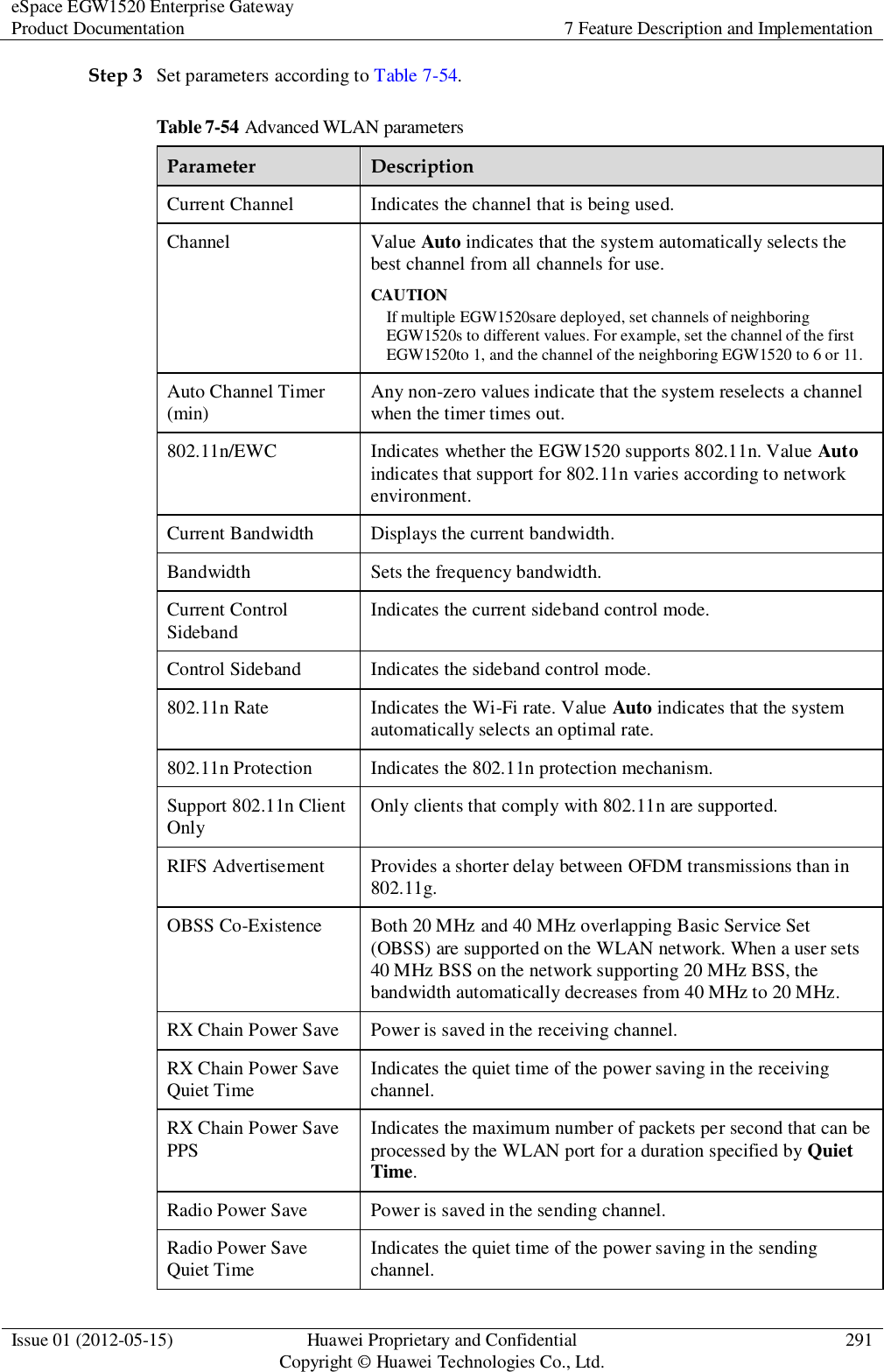
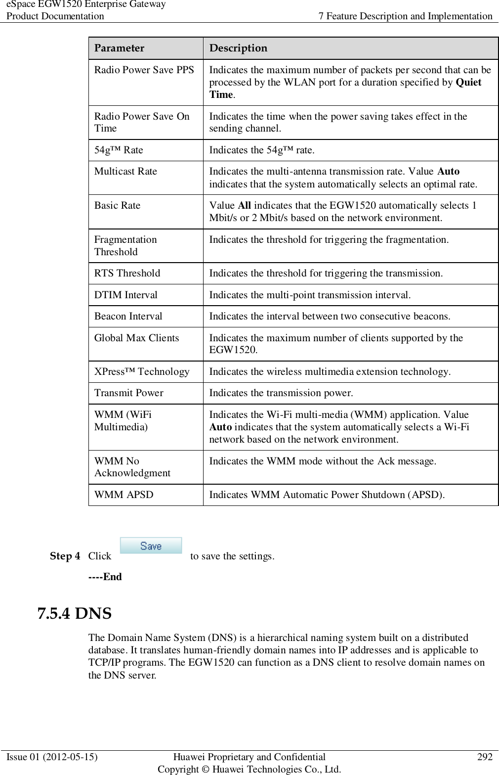
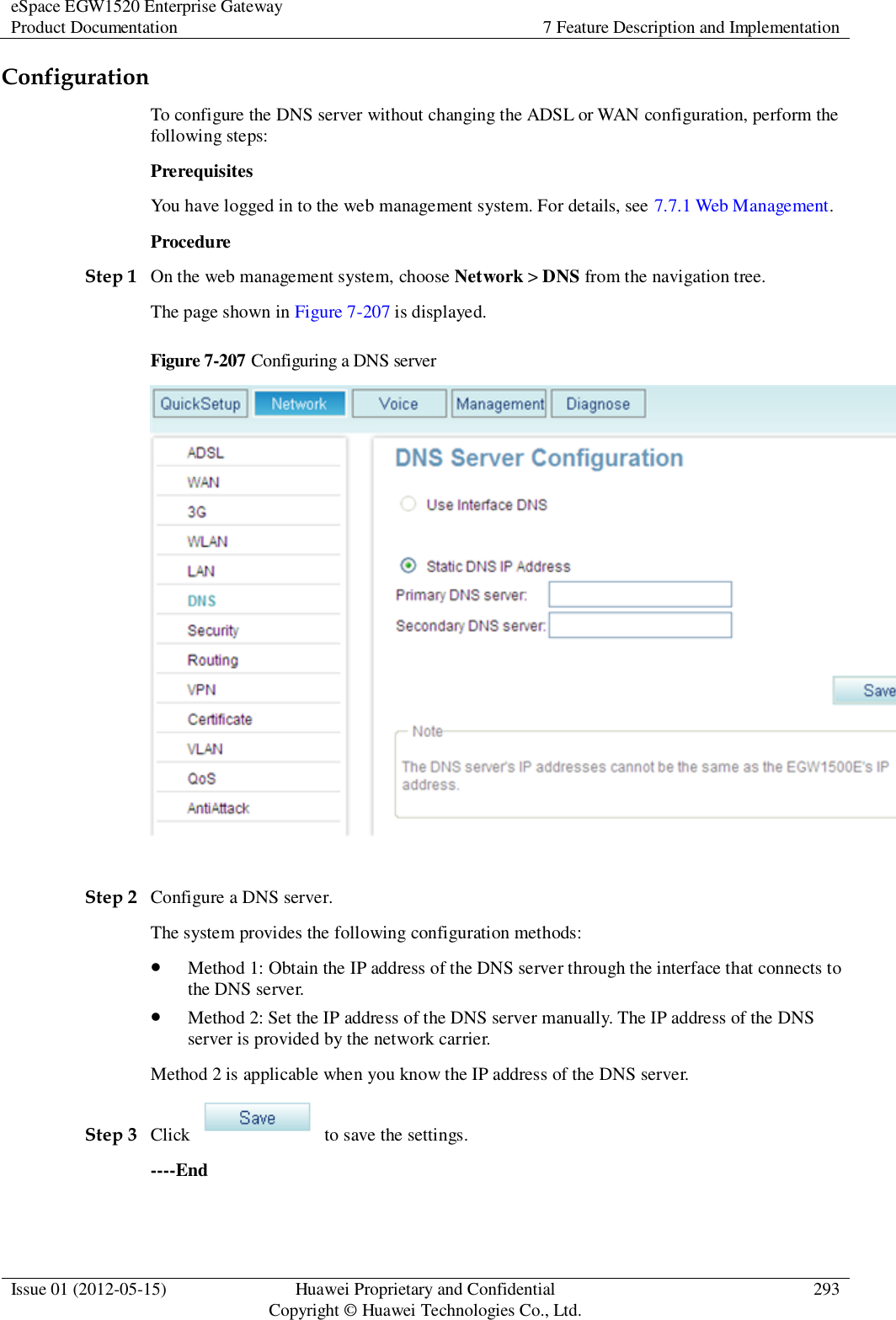
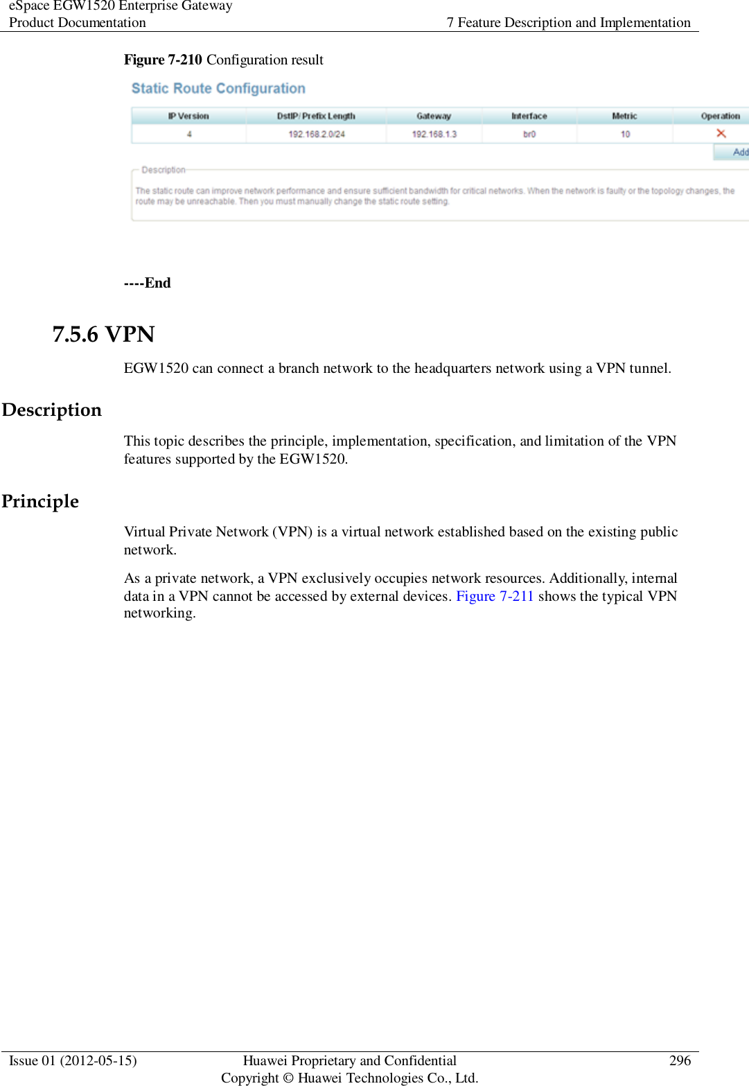
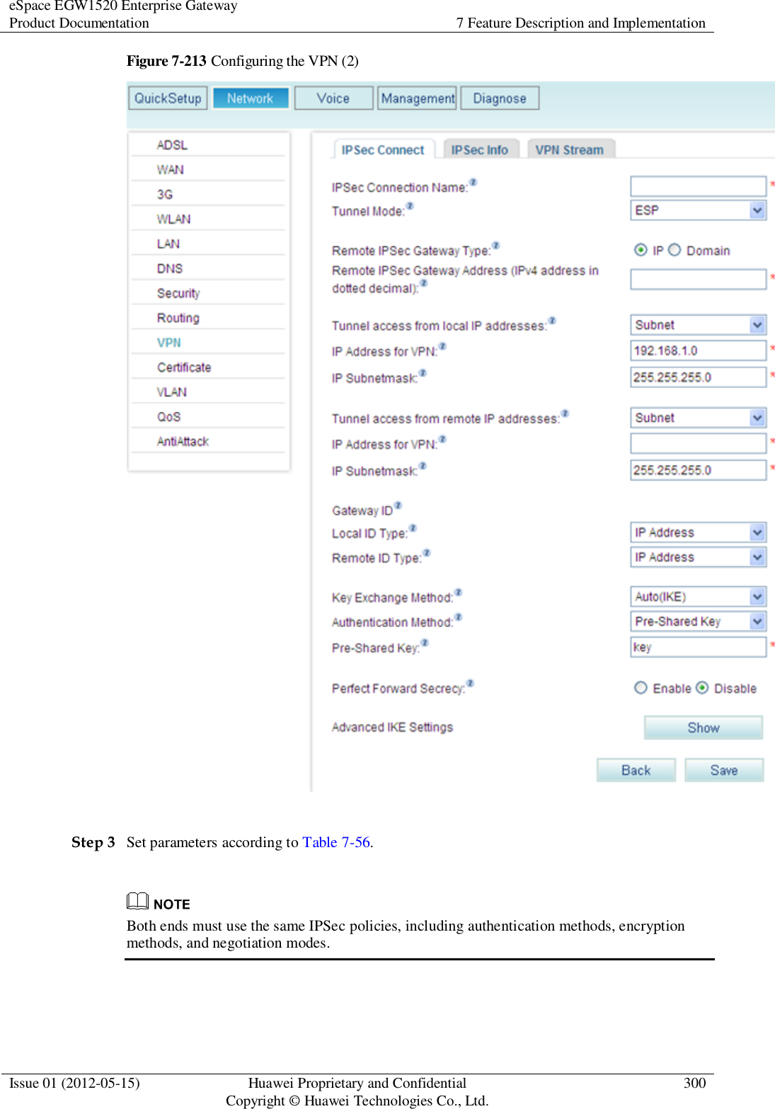
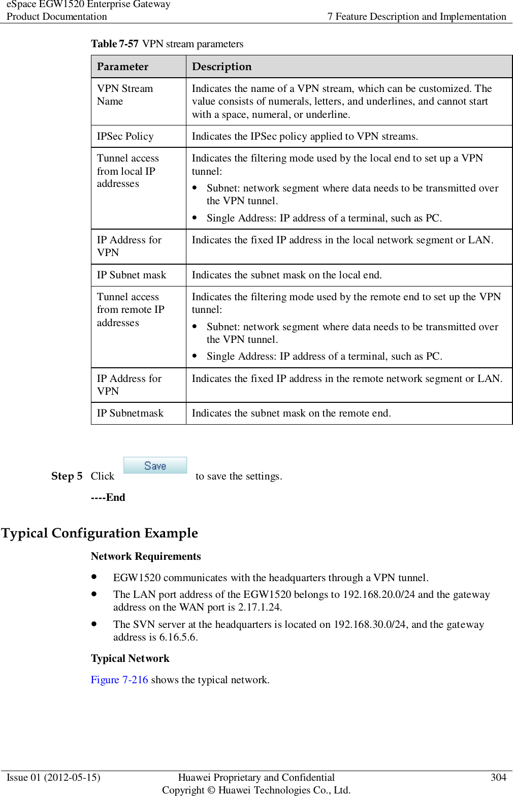
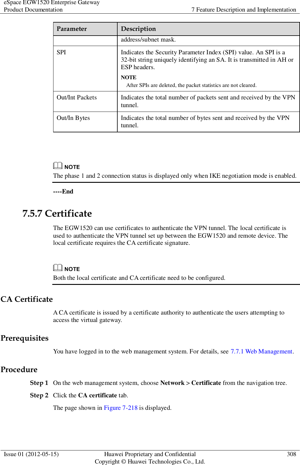
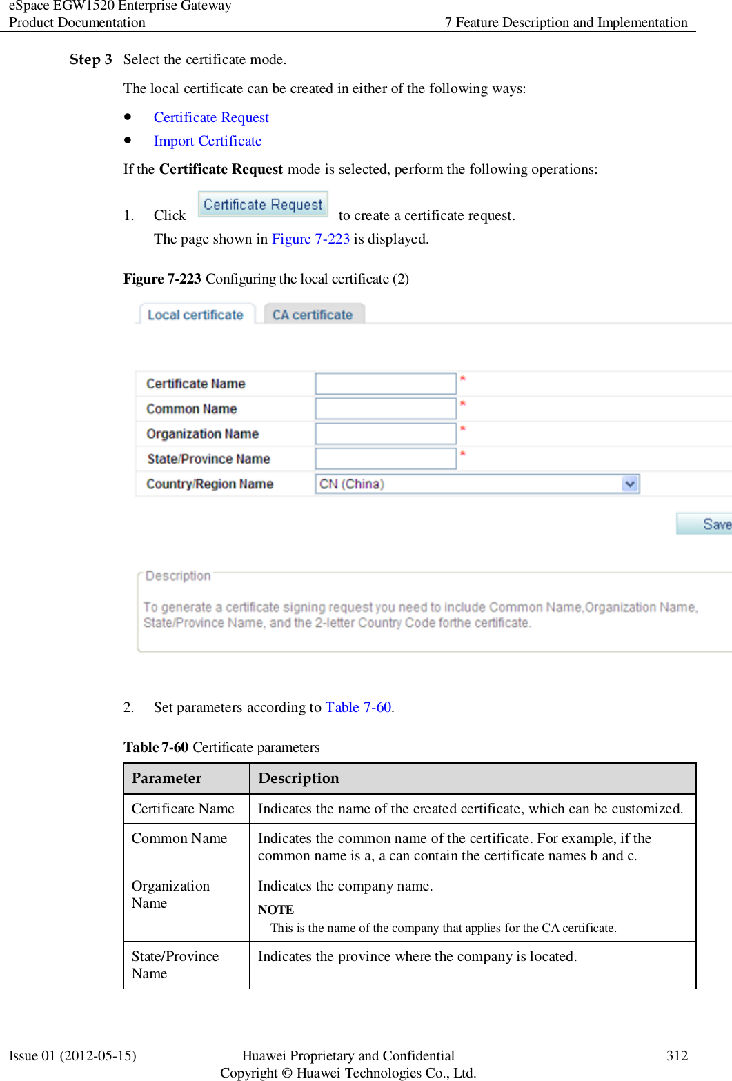
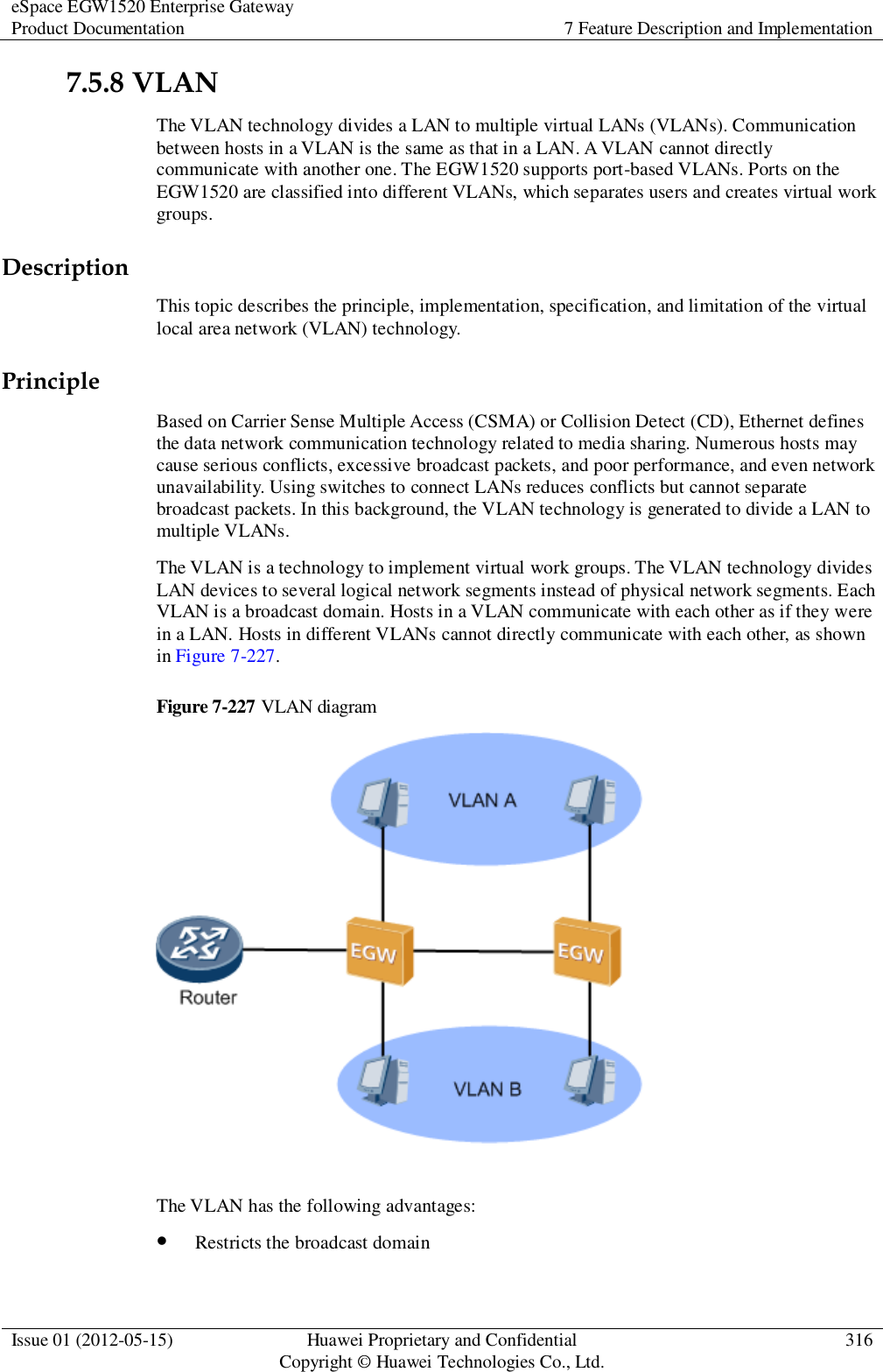
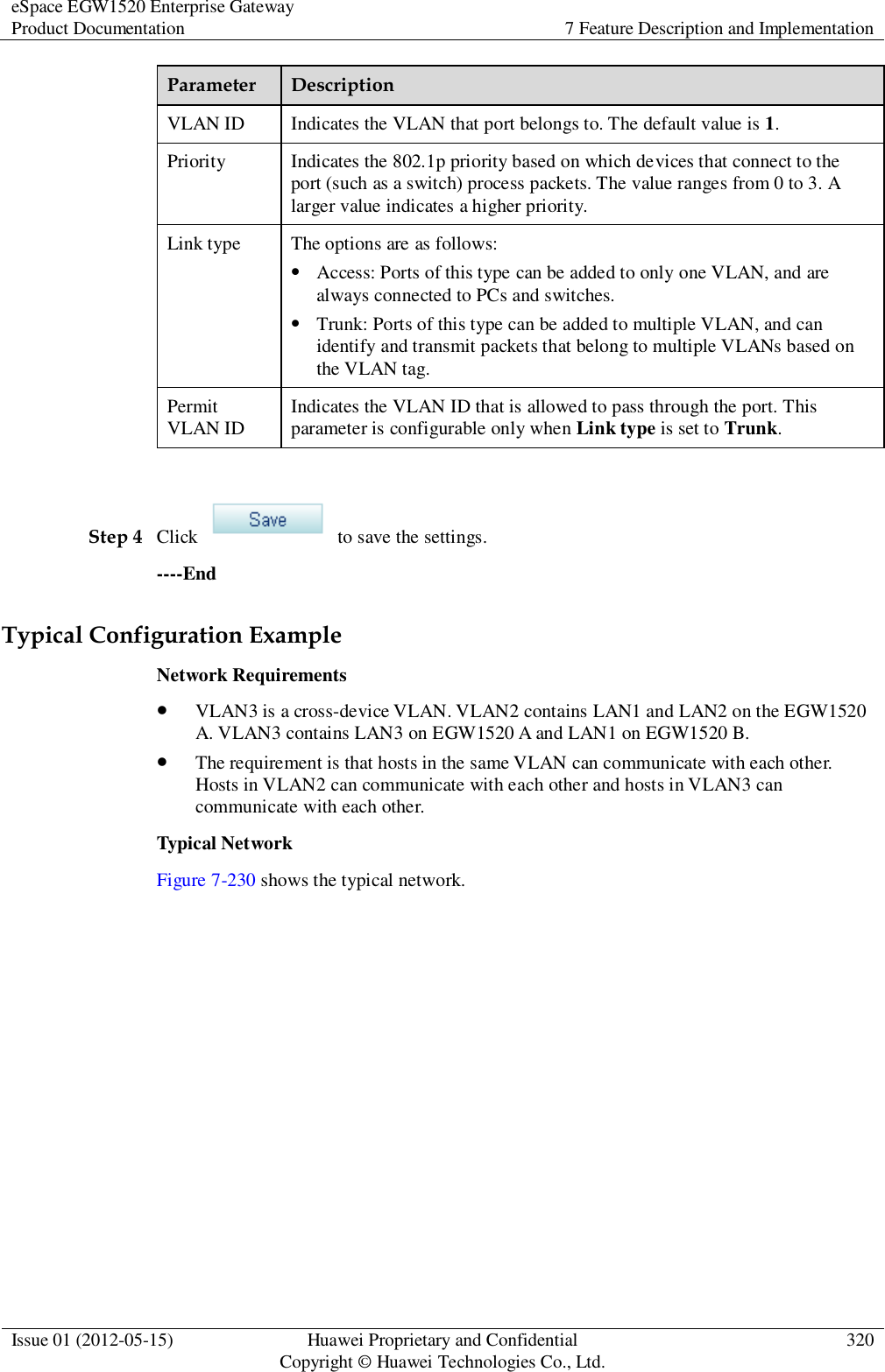
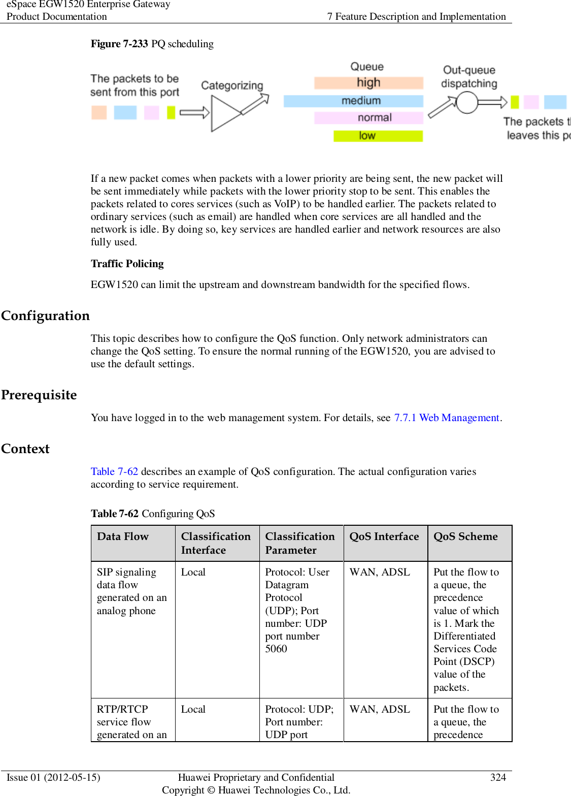
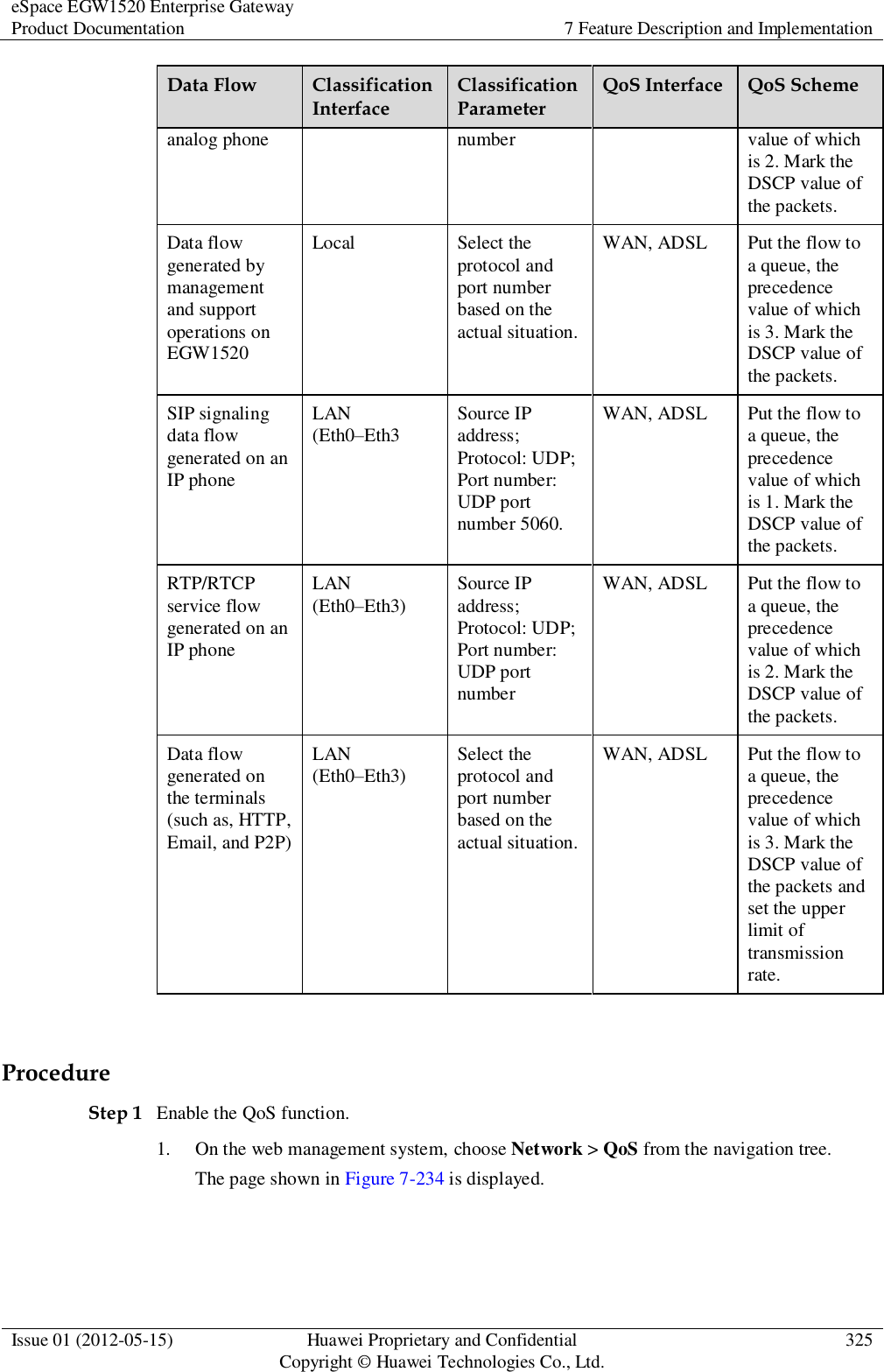
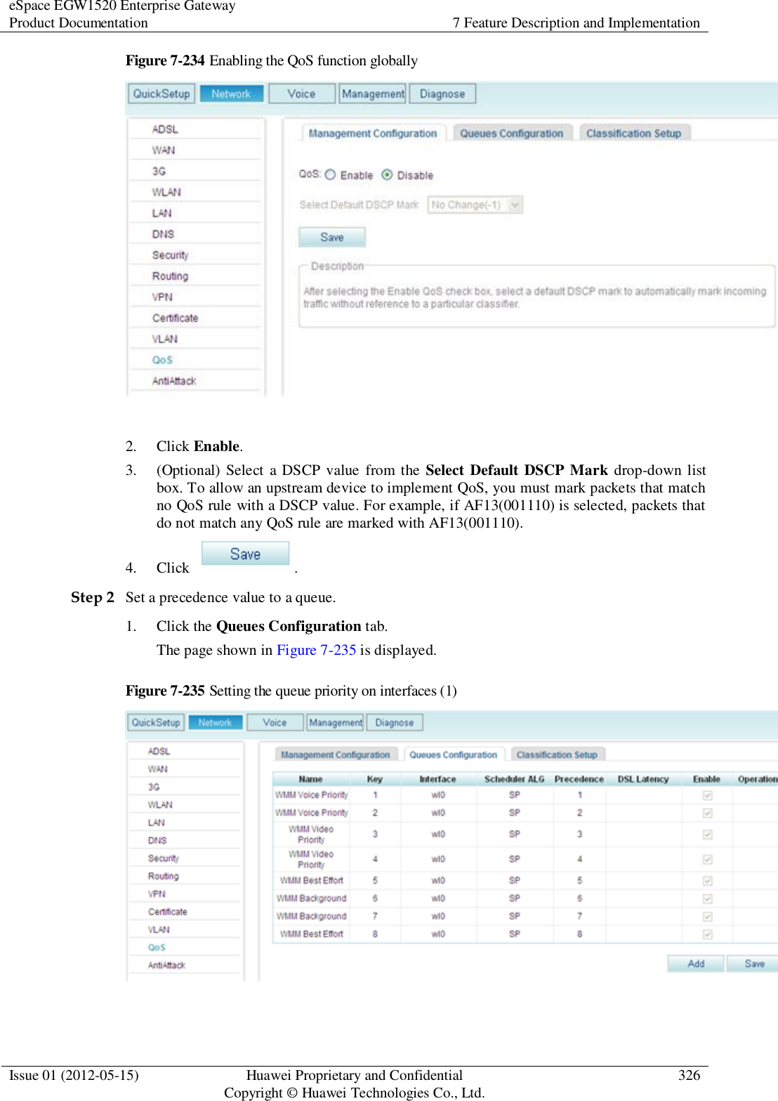
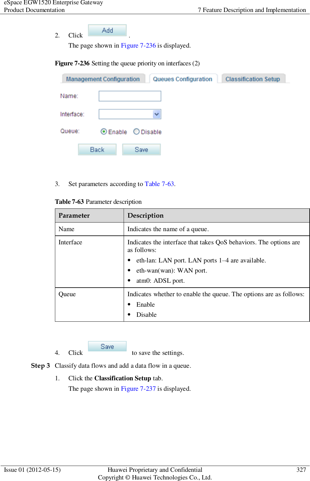
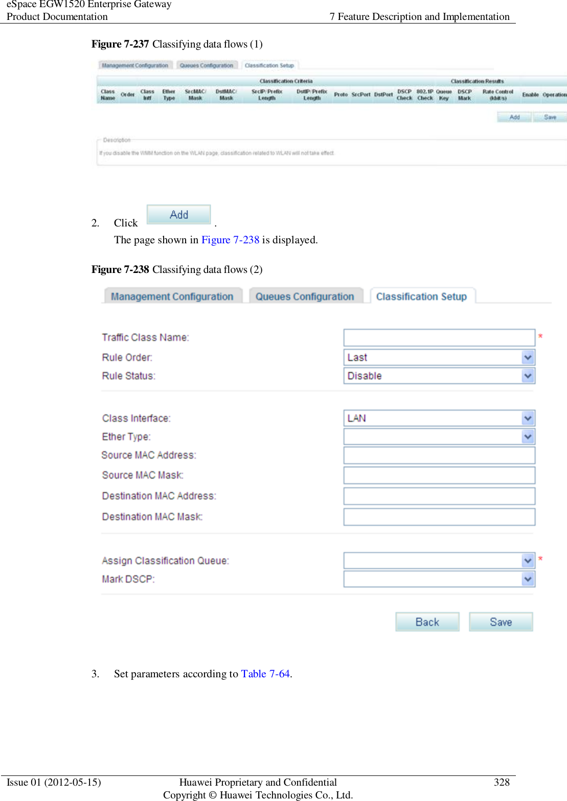
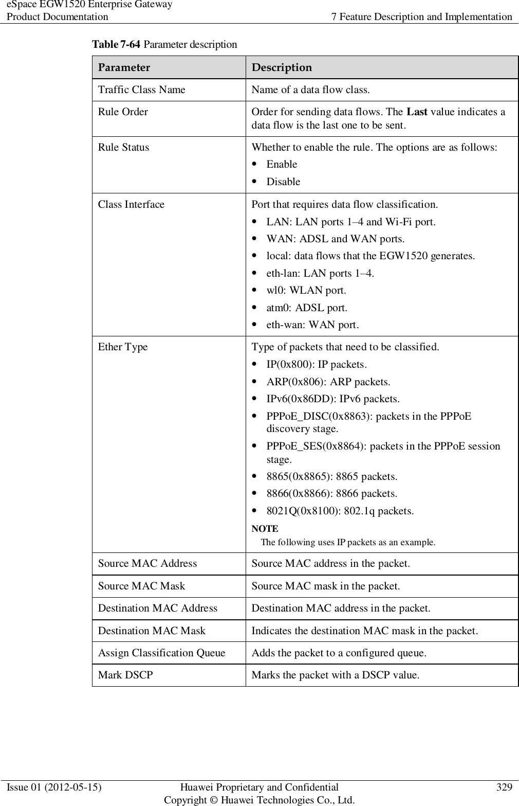
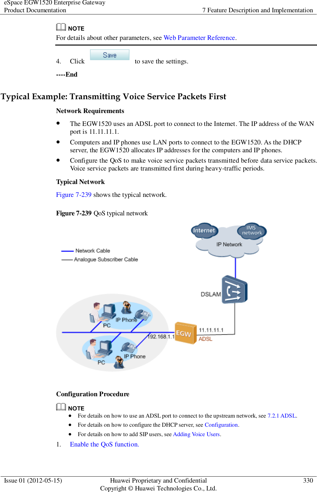
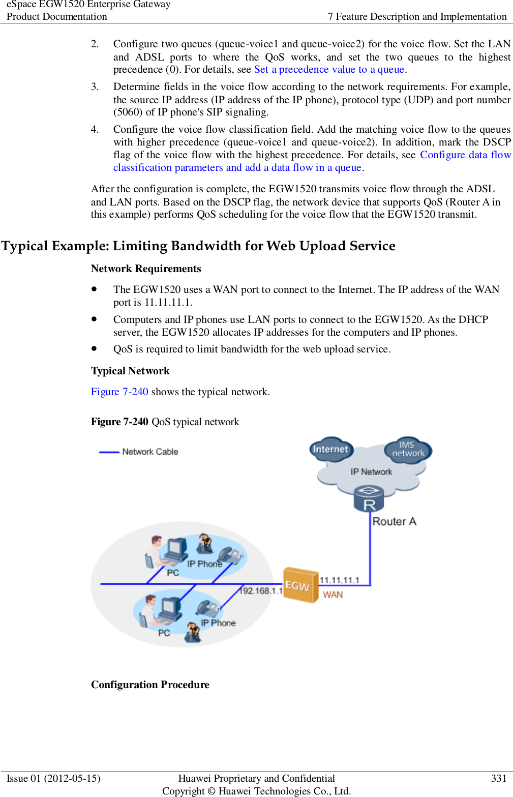
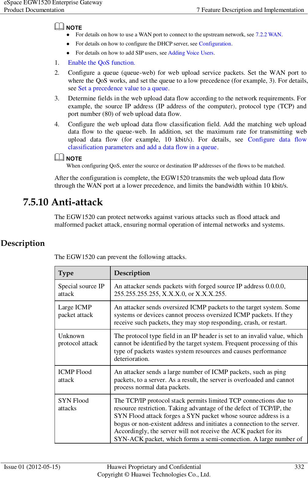
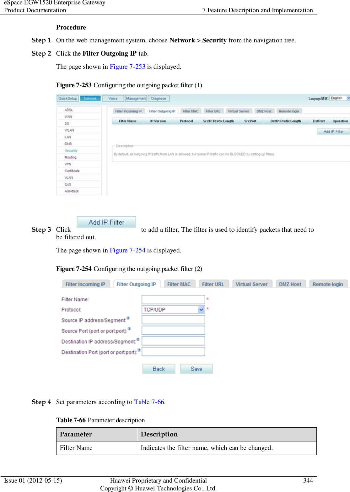
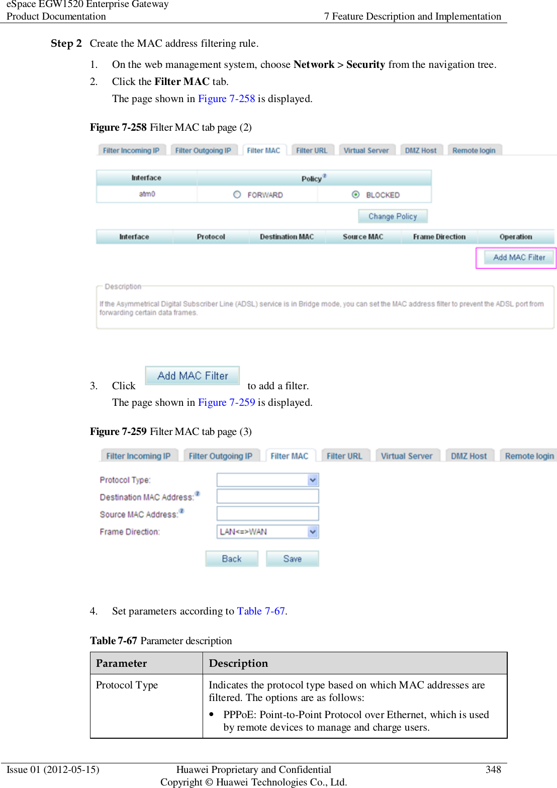
![eSpace EGW1520 Enterprise Gateway Product Documentation 7 Feature Description and Implementation Issue 01 (2012-05-15) Huawei Proprietary and Confidential Copyright © Huawei Technologies Co., Ltd. 295 Figure 7-209 Configuring the static route (2) Step 3 Set parameters according to Table 7-55. Table 7-55 Parameter description Parameter Description Destination IP address[/prefix length] Indicates the destination IP address and subnet mask length of the static route, for example, 192.168.2.0/24. Interface Indicates the outbound port of the static route through which packets are sent to the destination network segment. The options are as follows: br0/br0: ports on the LAN side (LAN ports 1–4 and Wi-Fi port). pppoe_0_0_35/ppp1: ADSL port. Gateway IP address Indicates the next hop IP address for the static route. Metric Indicates the route metric, which must be an integer. If there are multiple routes to a destination IP address, the route with the smaller route metric has the higher priority. This parameter is optional. Step 4 Click to save the settings. Figure 7-210 shows the configuration result.](https://usermanual.wiki/Huawei-Technologies/EGW1520A.UserManual-Part2-pdf/User-Guide-1894872-Page-97.png)