Huawei Technologies H3CSOHOWDR834G ADSL2+ 802.11b/g Wireless Router User Manual DWG 814E menual
Huawei Technologies Co.,Ltd ADSL2+ 802.11b/g Wireless Router DWG 814E menual
User Manual
DWG Series ADSL2+ Router Quick
Installation Manual
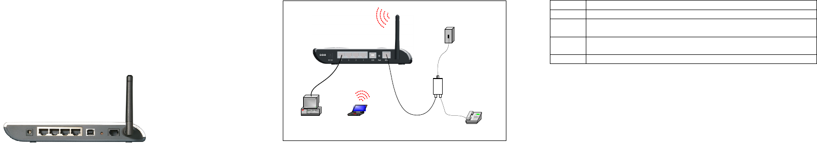
1 Appearance
Figure 1 DWG series rear view
2 Packing List
One DWG series ADSL2+ router
One power adapter
One telephone cable
One Ethernet cable
One USB cable
Two screws and two anchors
One Quick Installation Manual
One CD
Certificate of Quality
3 Hardware Installation
3.1 Installing ADSL Line
Figure 2 Installing ADSL Line
Two options are available for ADSL line connections:
Direct connect the ADSL line (same as a regular telephone port) to
the wall telephone line outlet.
As shown in Figure 2 , Connect the ADSL port and a telephone set
to a splitter, and then the splitter to the wall outlet of telephone line.
Thus you may place phone calls when accessing the Internet.
3.2 Connecting to PC or Ethernet
You can use crossover or straight through cables to connect the PC, HUB, or
switch to the MDI/MDIX auto-sensing interface of WDR series ADSL2+ router.
3.3 Connecting the Power Cord
(1) Attach one end of the power cord to the router and the other end to power
outlet. The power cord is accessory of the router.
(2) Observe the LED status one minute later. The following table lists the LEDs
and their normal expected status.
Table 1 LEDs
LED Normal status
Power The LED stays green. Check the power cord connection if the LED stays off.
Link The blinking of the LED indicates the ADSL activation and 20 to 30 seconds later,
the LED stays green.
LAN The green LED stays on. The blinking of the green LED indicates the data
transmission on the Ethernet port.
Diag This LED is off. If this LED turns on, contact the agents for help.
3.4 Configuring to Obtain an IP Address Automatically
Take the operation in the Windows 2000/XP operating system for example. The
steps are as follows:
(1) Click the <Start> button and choose the Settings > Control Panel options.
Double-click on the Network Dial-up Connections icon from the Control Panel
window.
(2) Right-click on the Local Area Connection icon and select the Properties from
the pop-up menu. Next, choose the Internet Protocol (TCP/IP) from the Local
Area Connection Properties tabbed interface and click <Properties> to proceed.
(3) When the Internet Protocol (TCP/IP) Properties interface pops up, select the
Obtain an IP address automatically and Obtain DNS server address
automatically options, then click <OK>.
3.5 Logon
(1) Check the configuration of the proxy server. Disable the proxy server first
when the PC is accessing the Internet through proxy server.
(2) Use the Web browser. Enter http://192.168.1.1 in the address bar (by default,
the IP address of the WDR ADSL2+ router is 192.168.1.1).
(3) Log onto the Web setup manager. A new window appears prompting you to
enter the user name and password. For the first logon, use the default
administrator user name admin with the password admin. The password can be
modified after entering the management interface.
Telephone
Desktop PC
Telephone por
t
A
DSL2+ Wireless Route
r
NoteBook
Splitte
r
LINE
ADSL PHONE
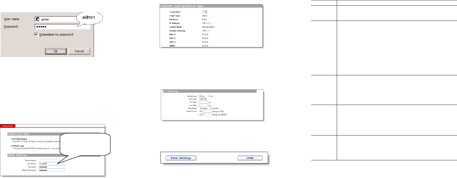
Figure 3 Entering the user name and password
4 Setup
After you log onto the Web page, follow the simple steps to finish the quick
configuration:
(1) Click <Quick Start> from the Navigation bar to the Quick Start window.
Select the PPPoE as the login type, and then input the user name and password
assigned by ISP. You may leave the Service Name box untouched. Then click
<Save Settings> to proceed.
Figure 4 Setting parameters
(2) Click <Status> from the Navigation bar to enter the Status tabbed page. You
can find that the IP Address item presents an IP address of the public network
instead of the original 0.0.0.0.
Figure 5 Checking status
(3) If you obtain no public IP address, click <WAN Setup> from the Navigation
bar. Then you can view the VPI/VCI value that the system detects automatically.
If the values are incorrect, select the Disable option and input the values
manually. For the correct VPI/VCI value, contact your local ISP.
Figure 6 Checking the VPI/VCI value
At last, click <Save Settings> in the WAN tabbed interface to finish the
configuration.
Figure 7 Save settings
5 Quick Troubleshooting
Table 2 Quick troubleshooting
Symptom Solution
The ADSL
Link LED
stays OFF.
The RJ-11 telephone cable must be used and connected to the ADSL and
telephone ports correctly.
Access to
the Internet
fails.
Make sure that:
1) You have followed all the steps described above and found no
problems.
2) The IP address of your PC is in the range of allocated valid addresses.
To check it, select the Run option from the Start menu. In the pop-up
window, input winipcfg (in Win98 operating system) or ipconfig (in
Win2000/XP operating system) for the IP address checking.
3) You can ping the IP address of the gateway (192.168.1.1).
4) You have performed the correct DNS configuration on your PC.
5) You have disabled the proxy server.
6) The correct VPI/VCI value is set on the WAN Setup window.
You forget
the login
password.
Both of the default user name and password are admin. If you have
changed the password but forget it, press the Reset button for 5 seconds
to restore the default settings on the router. Then you can access the Web
page with the default user name and password.
Note: The reset function restores the settings to the factory default
settings.
Access to
the router
Web pages
fails.
Make sure that:
1) The LAN LED is ON.
2) The settings of TCP/IP properties are correct.
3) You have entered the correct user name and password.
If you still cannot access the router Web pages, press the Reset button for
5 seconds to restore the default settings.
The
modification
on the Web
pages fails
to save.
You need to click <Save Settings> to save every modification that you
have made.
Input the username
and password
assigned by ISP
FCC Caution:
1. This device complies with Part 15 of the FCC rules. Operation is subject to the
following two conditions:
(1) This device may not cause harmful interference, and
(2) This device must accept any interference received, including interference that may
cause undesired operation.
2. This device and its antenna(s) must not be co-located or operating in conjunction
with any other antenna or transmitter.
3. Changes or modifications to this unit not expressly approved by the party responsible
for compliance could void the user authority to operate the equipment.
4. This equipment has been tested and found to comply with the limits for a Class B
digital device, pursuant to Part 15 of the FCC Rules. These limits are designed to
provide reasonable protection against harmful interference in a residential installation.
This equipment generates, uses and can radiate radio frequency energy and, if not
installed and used in accordance with the instructions, may cause harmful interference
to radio communications. However, there is no guarantee that interference will not
occur in a particular installation. If this equipment does cause harmful interference to
radio or television reception, which can be determined by turning the equipment off and
on, the user is encouraged to try to correct the interference by one or more of the
following measures:
-- Reorient or relocate the receiving antenna.
-- Increase the separation between the equipment and receiver.
-- Connect the equipment into an outlet on a circuit different from that to which the
receiver is connected.
-- Consult the dealer or an experienced radio/TV technician for help.
5. This equipment complies with FCC RF radiation exposure limits set forth for an
uncontrolled environment. This equipment should be installed and operated with a
minimum distance of 20 centimeters between the radiator and your body.