Huawei Technologies HG520C Home Gateway User Manual 00 1 Cover
Huawei Technologies Co.,Ltd Home Gateway 00 1 Cover
Contents
- 1. manual
- 2. Users Manual
manual

EchoLife HG520c Home Gateway
User Guide
HUAWEI TECHNOLOGIES CO., LTD.

EchoLife HG520c Home Gateway
V100R001
User Guide
Issue 01
Date 2009-04-14
Part Number 103139

Huawei Technologies Co., Ltd. provides customers with comprehensive
technical support and service. Please feel free to contact our local office
or company headquarters.
Huawei Technologies Co., Ltd.
Address: Huawei Industrial Base
Bantian, Longgang
Shenzhen 518129
People's Republic of China
Website: http://www.huawei.com
Email: terminal@huawei.com
Copyright © Huawei Technologies Co., Ltd. 2009. All
rights reserved.
No part of this document may be reproduced or transmitted in any form or
by any means without prior written consent of Huawei Technologies Co.,
Ltd.
Trademarks and Permissions
and other Huawei trademarks are trademarks of Huawei
Technologies Co., Ltd.
All other trademarks and trade names mentioned in this document are the
property of their respective holders.
Notice
The information in this document is subject to change without notice.
Every effort has been made in the preparation of this document to ensure
accuracy of the contents, but all statements, information, and
recommendations in this document do not constitute the warranty of any
kind, express or implied.
Contents
1 Safety Precautions..................................................................................... 1
2 Connecting the Cables and Getting Started............................................ 4
2.1 Simple Connection.......................................................................................4
2.2 Connecting One Telephone..........................................................................5
2.3 Connecting Multiple Telephones .................................................................6
2.4 Getting Started .............................................................................................7
3 Setting the Network-Access Parameters ................................................. 7
3.1 Accessing the Network Through the Embedded PPP Dial-Up Software of the
HG520c ...............................................................................................................7
3.2 Accessing the Network Through the PPP Dial-Up Software on the Computer
.............................................................................................................................8
4 Configuring the Wireless Mode ............................................................... 9
5 Configuring the HG520c........................................................................... 9
5.1 Changing the Administrator Password Used for Logging In to the Web
Configuration Page..............................................................................................9
5.2 Changing the IP Address............................................................................10
5.3 Restoring Default Settings..........................................................................10
6 FAQs......................................................................................................... 11
7 Appendix.................................................................................................. 14
7.1 Indicators....................................................................................................14
i
7.2 Interfaces and Buttons................................................................................15
7.3 Default Settings..........................................................................................15
7.4 Technical Specifications.............................................................................15
ii

1 Safety Precautions
Thank you for purchasing Echolife HG520c Home Gateway (hereinafter referred to as
the HG520c).
For safety purposes, carefully read through these safety precautions and observe them
during operation.
Basic Requirements
z Keep the device dry during storage, transportation, and operation of the device.
z Prevent collision of the device with other objects during storage, transportation, and
operation of the device.
z Do not attempt to dismantle the device. In case of any fault, contact the authorized
maintenance center for assistance or repair.
z Without prior written consent, no organization or individual is permitted to make
any change to the structure, safety, and performance design of the device.
z While using the device, observe all applicable laws, directives and regulations, and
respect the legal rights of other people.
Environmental Requirements
z Place the device in a well-ventilated place. Do not expose the device to direct
sunlight.
z Keep the device clean, free of dust and stain.
z Do not place the device near a water source or in a damp area.
z Place the device on a stable surface.
z Do not place any object on the top of the device. Reserve a minimum space of 10
cm at the four sides and on the top of the device for heat dissipation.
z Do not place the device on or near inflammable materials such as foam.
z Keep the device away from heat source or fire, such as a radiator or a candle.
z Keep the device away from any household appliances with strong magnetic field or
electric field, such as microwave oven, refrigerator, or mobile phone.
1
Operation Requirements
z Do not allow children to play with the device or accessories.Swallowing the
accessories may be fatal.
z Use the accessories such as the power adaptor provided or authorized only by the
manufacturer.
z Make sure that the device does not get wet. If water gets into the device, disconnect
the power supply immediately and unplug all the cables connected to the device.
z The power supply of the device must meet the requirements of the input voltage of
the device.
z Before plugging or unplugging any cable, shut down the device and disconnect the
power supply.
z While plugging or unplugging any cable, make sure that your hands are dry.
z Do not step on, pull, or stretch any cable. Otherwise, the cable may get damaged,
leading to malfunction of the device.
z Do not use old or damaged cables.
z Keep the power plug clean and dry, to prevent electric shock or other dangers.
z During lightning, disconnect the device from the power supply and unplug all the
cables connected to the device, such as the power cable, telephone cable, and RF
cable, to prevent lightning strike.
z If the device is not used for a long time, disconnect the power supply and unplug the
all the cables connected to the device.
z If smoke, sound, or smell is emitted from the device, stop using the device
immediately, disconnect the power supply, unplug the power supply and other
cables, and remove the batteries. Contact the authorized maintenance center for
repair.
z Make sure that no object (such as metal shavings) enters the device through the heat
dissipation vent.
z Do not scratch or abrade the shell of the device. The shed painting may lead to skin
allergy or malfunctions of the device. If the shed painting material drops into the
host, a short circuit may occur.
Cleaning Requirements
z Before cleaning the device, stop using it, disconnect the power supply, and unplug
all the cables connected to the device.
z Do not clean the device cover with any cleaning solution or cleanser spray. Use a
piece of soft cloth to clean the device cover.
2

Environmental Protection
Do not dispose the abandoned device or battery in a garbage can. You need to dispose it
according to the local regulations on disposing of device packing materials, exhausted
battery and abandoned device, and support the recycling activity.
Wireless Product Usage Requirements
z Keep the device away from magnetic storage devices (e.g., a magnetic card or a
floppy disk), to prevent loss of the stored information.
z Stop using the device or disconnect the power supply in situations where wireless
device is prohibited or using of a wireless device leads to interference or danger.
z The user who uses an electronic assistant medical-treatment device needs to
confirm with the service center regarding the effects of the radio wave on this
device.
z Do not take the device to the operation theater, Intensive Care Unit (ICU) or the
Coronary Care Unit (CCU).
z When using the device maintain distance of 3 cm between your body and the
antenna of the device.
z In the area with inflammable or explosive materials, turn off your wireless device,
and follow the relevant instructions given in the label, to prevent explosion or fire.
z Protect the wireless device and its accessories, and use it in a clean and dust-free
environment. Make sure that the wireless device does not come in contact with
flame or a cigarette that is lit.
z Make sure that the wireless device and its accessories are dry.
z Do not drop, throw or try to bend your wireless device.
z Do not place the wireless device and its accessories in high temperature areas.
After the HG520c is used for a certain period of time, the cover will be
heated, which will not affect the function of the HG520c.
3
2 Connecting the Cables and Getting
Started
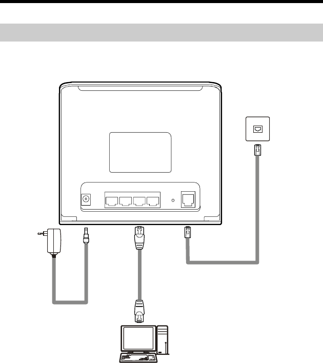
2.1 Simple Connection
If your telephone line is used for the broadband network access only and you do not
need to use a telephone, take the following figure as a reference for connecting the
cables.
1
2
3
POWER
LAN4 LAN 3 LAN 2 LAN 1
RESE T
ADS L
1 Telephone jack on the wall 2 Power adapter 3 Computer
4
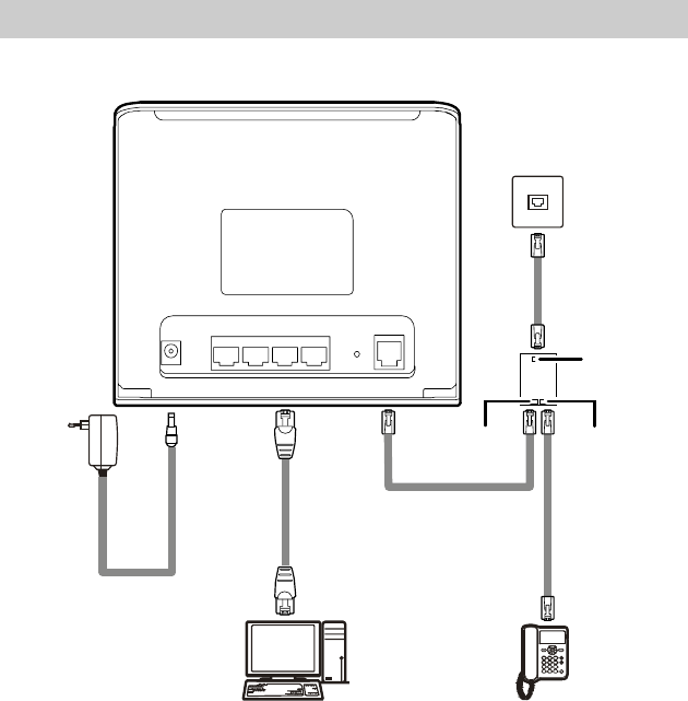
2.2 Connecting One Telephone
If your telephone line is used for both the broadband network access and a telephone
connection, take the following figure as a reference for connecting the cables.
####
#### ####
1
3
45
PHONE
LINE
MODEM
2
POW ER
LAN4 LAN 3 LAN 2 LAN 1
RESE T
ADS L
1 Telephone jack on the wall 2 Splitter
3 Power adapter 4 Computer
5 Telephone
5
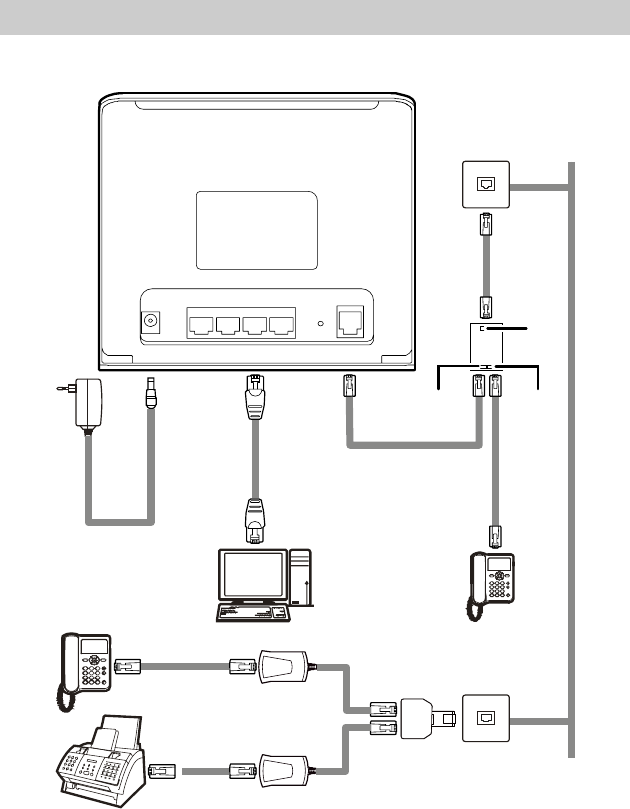
2.3 Connecting Multiple Telephones
If your telephone line is used for the broadband network access, telephone connections,
and fax connections, take the following figure as a reference for connecting the cables.
####
#### ####
1
3
45
PHONE
LINE
MODEM
2
POW ER
LAN 4 LAN3 LAN 2 LAN 1
RESE T
ADS L
1
7
6
5
7
8
1 Telephone jack on the wall 2 Splitter 3 Power adapter 4 Computer
5 Telephone 6 Fax 7 Microfilter 8 T connector
6

2.4 Getting Started
Press the power button on the top of the HG520c to power on the HG520c.
After you power on the HG520c, the ADSL indicator blinks (for less than three
minutes), indicating that the HG520c is being activated. Later, the ADSL indicator
becomes on. The POWER indicator is also on, indicating that the HG520c is working.
3 Setting the Network-Access Parameters
By configuring the HG520c and the computer, you can choose any of the following
methods to surf the Internet:
z Accessing the Network Through the Embedded PPP Dial-Up Software of the
HG520c
z Accessing the Network Through the PPP Dial-Up Software on the Computer
3.1 Accessing the Network Through the
Embedded PPP Dial-Up Software of the HG520c
If you select this method for accessing the network, the HG520c starts to set up dial-up
connection automatically after the startup. You can access the network after you power
on the computer. You do not need to install any special dial-up software on the
computer or perform the dial-up operations on the computer. To configure the HG520c
and the computer for the network access, do as follows:
Step 1 Log in to the Web configuration page.
1. Launch the Internet Explorer on the computer. Enter http://192.168.1.1
in the address bar and press Enter.
2. In the displayed dialog box, enter the user name and the password, and
then click OK.
By default, both the user name and the password are admin. After the password is
verified, you can access the Web configuration page.
Step 2 Enable the embedded dial-up function.
1. In the navigation tree on the left of the configuration page, choose Basic >
WAN Setting.
2. Select a PVC number, such as 1, from the PVC drop-down combo box.
3. In the VPI and VCI text boxes, enter the VPI and VCI values that are
provided by the network operator .
4. Select Yes from the Active drop-down combo box and select Routing
from the Mode drop-down combo box.
7

5. Enter the operator name, user name, and password in the Login
Information dialog box and keep the default settings of other parameters.
6. Click Submit to save the settings.
After you complete the preceding settings, you can surf the Internet.
You need to perform the preceding operations only once. The next time when you
power on the computer, you can surf the Internet without performing any configuration.
3.2 Accessing the Network Through the PPP
Dial-Up Software on the Computer
If you select this method for accessing the network, you need to install and configure
the dial-up software on the computer. In addition, you need to perform the dial-up
operations on the computer each time after the startup of the computer. To configure the
HG520c and the computer for the network access, do as follows:
Step 1 Set the working mode of the HG520c to Bridge.
For details, refer to the procedure for enabling the embedded dial-up function described
in Step 2 in section 3.1 "Accessing the Network Through the Embedded PPP Dial-Up
Software of the HG520c." Select Bridge from the Mode drop-down combo box.
Step 2 Install and configure the PPP dial-up software on the computer.
The PPP dial-up software is preinstalled on certain computer operating systems. To
create a dial-up connection, do as follows (taking the Windows XP operating system as
an example):
1. Choose Start > All Programs > Accessories > Communications >
Network Connections.
2. Click Create a new connection in Network Tasks to display the New
Connection Wizard window, and then click Next.
3. Select Connect to the Internet, and then click Next.
4. Select Set up my connection manually, and then click Next.
5. Select Connect using a broadband connection that requires a user
name and password, and then click Next.
6. Enter the name (as desired) of the dial-up connection in ISP Name, and
then click Next.
7. Select Anyone's use or My use only, and then click Next.
8. Enter the user name and password provided by the operator and used for
the dial-up connection, and then click Next.
9. Select Add a shortcut to this connection to my desktop, and then click
Finish.
An icon for the dial-up connection is displayed on the desktop of the computer.
8

You need to perform the preceding operations only once for creating a network
connection. After the network connection is created, to access the network,
double-click the icon for the dial-up connection, and then click Connect in the
displayed dialog box.
4 Configuring the Wireless Mode
In the wireless mode, the HG520s enables you to access the Internet without connecting
a cable.
To change the Wireless Mode, do as follows:
Step 1 Log in to the Web configuration page.
Step 2 Configure the wireless mode.
1. In the navigation tree on the left of the configuration page, choose Basic >
Wireless Lan.
2. Select Enable from Access Point.
3. Enter the name for your wireless network in the SSID.
4. Select WPA-PSK from the Authentication Type drop-down combo
box.
5. Enter the password for your wireless network in the Pre-Shared Key and
and keep the default settings of other parameters.
6. Click Submit to save the settings.
5 Configuring the HG520c
5.1 Changing the Administrator Password Used
for Logging In to the Web Configuration Page
For safety reasons or to make the password easy to remember, you can change the
log-in administrator password after logging in to the Web configuration page.
To change the password, do as follows:
Step 1 Choose Tools > System Management in the navigation tree to display the
system management page.
Step 2 Click to display a dialog box.
Step 3 Enter the old password and the new password, and then enter the new
password again in the Retype to confirm text box for confirmation.
9

Step 4 Click Submit.
After you change the password successfully, the current page jumps to the page for
logging in to the Web configuration page. To log in to the Web configuration page,
e ne
enter th w password, and then click OK.
logging in to the Web configuration page are restored to default
values.
If you cannot remember the user name and password that have been
changed, you can restore the default settings of the HG520c by pressing the
RESET button on the panel. In this way, the user name and the password
used for
5.2 Changing the IP Address
To make the IP address easy to remember, you can change the IP address after logging
Step 1 LAN Setting in the navigation tree to display the LAN
ddress in the IP Address text box.
IP address of the HG520c so that the computer can access the Web configuration page.
in to the Web configuration page.
To change the IP address, do as follows:
Choose Basic >
settings page.
Step 2 Enter a new IP a
Step 3 Click Submit.
After the IP address is changed successfully, to log in to the Web configuration page,
you need to launch the Internet Explorer and enter the new IP address in the address bar.
Ensure that the IP address of the computer is in the same network segment as that of the
5.3 Restoring Default Settings
To restore default settings, log in to the Web configuration page, and then do as
:
igation tree to display the reboot page.
Default Settings.
Web configuration page by entering the user name and the password that are admin.
follows
Step 1 Choose Tools > Reboot in the nav
Step 2 Select Factory
Step 3 Click Restart.
After the preceding operations, the page jumps to the login page. You can log in to the
10

FAQs 6
What can
Step 1 Che
If the POWE
1.
the
the
he socket through the
Step 2 Aft k
If the AD llows:
ay special
e and splitter.
from the electric
ic fields.
If the AD
Step 3 Che indicator of the terminal is on.
If the LA
r is
If the LA
Step 4
Take a co river
for the ne
1.
er
I do if I cannot visit Web sites through the terminal?
ck whether the POWER indicator of the terminal is on.
R indicator is off, perform further checks as follows:
Ensure that the power switch of the terminal is turned on.
2. Ensure that electricity comes from the socket and that the input power
of the socket meets the requirements described on the label of the
terminal power adapter. If the voltage is unsteady, for example, if
voltage is too high or too low, do not use the terminal. Wait until
voltage restores to its normal level, and then use the terminal.
3. Ensure that the terminal is properly connected to t
power adapter.
If the POWER indicator is still off, contact an authorized maintenance center.
er powering on the terminal, wait for about three minutes. Then chec
whether the ADSL indicator of the terminal is on.
indicator blinks for a long time, perform further checks as fo
SL
1. Ensure that telephone lines are properly connected. P
attention to the connection between the telephone lin
2. Ensure that terminal cables or telephone lines are far
appliances that generate strong magnetic or electr
3. Replace telephone lines.
SL indicator still blinks, contact your network operator.
ck whether the LAN
N indicator is off, perform further checks as follows:
1. Ensure that the network adapter of the computer is enabled.
2. Ensure that the network cable between the terminal and the compute
properly connected.
3. Remove and then insert the network cable or replace the network cable.
N indicator is still off, contact an authorized maintenance center.
Check whether the driver for the network adapter is properly installed.
mputer that runs Windows XP as an example. To check whether the d
twork adapter is installed, do as follows:
On the desktop, right-click My Computer and choose Manage.
2. In the navigation tree of the Computer Management window, choose
Device Manager.
3. In the right pane of the Computer Management window, click
Network adapters to view the information about the network adapt
11

of the computer.
ork adapter is found or if a question mark (
If no netw ?) or an exclamation mark (!) is
r the
that
ed by the PPP dialing software.
The user
Step 6 Che you can use the PPP dialing software to dial successfully.
If you can ully, perform further
l. After
If the pro operator.
Step 7 eb browser is correctly eb
browser is correctly configured, do as follows:
2.
3.
4. N) settings group box, click LAN
e Proxy server group box of the Local Area Network (LAN)
check box is not selected.
Try to access multiple other Web sites to check whether the terminal can
s, contact your network service
r.
displayed next to the icon of the network adapter, you can infer that the driver fo
network adapter is not properly installed. In this case, re-install the driver for the
network adapter of the computer.
Step 5 Ensure that you have entered the correct user name and user password
are requir
name and the user password are provided by your network operator.
ck whether
not use the PPP dialing software to dial successf
checks as follows:
1. Stop the PPP dialing software and then power off the termina
five minutes, power on the terminal and use the PPP dialing software to
dial again.
2. Restore the default settings of the terminal.
blem persists, contact your network
Check whether the proxy server of the W
configured. Take the Internet Explorer installed on a computer that runs
Windows XP as an example. To check whether the proxy server of the W
1. Launch the Internet Explorer.
Choose Tools > Internet Options.
In the Internet Options dialog box, click the Connections tab.
In the Local Area Network (LA
Settings.
5. In th
Settings dialog box, ensure that Use a proxy server for your LAN
(These settings will not apply to dial-up or VPN connections).
Step 8 access.
If the terminal still cannot access other Web site
provide
What can I do if Web pages often cannot be displayed during Web page browsing and
can be d splayed after the terminal is restarted? i
nnected to the telephone line through a splitter.
Step 1 Ensure that the terminal and other devices such as telephones or fax
machines are co
12

For detai .
Step 2
bility of the network
nnection is affected.
icrowave ovens, refrigerators, or
ls about how to install a splitter, see the related description in the manual
Ensure that telephone lines are properly connected.
If the telephone lines are improperly connected, the sta
co
Step 3 Check the positions of your terminal and computer. Ensure that they are far
from the electric appliances such as m
cordless telephones that generate strong magnetic or electric fields.
If the problem persists, contact your service provider.
After a broadband terminal is installed, does Internet access degrade call quality or do
telephone calls lower the Internet access rate?
No. The terminal uses the frequency division multiplexing (FDM) and splitter
the two types of
ied by different
technologies to separate voice signals from data signals. Although
signals are transmitted through one telephone line, they are carr
frequency bands. Therefore, they do not interfere with each other. In this case, you
can make a telephone call and access the Internet at the same time, without degrading
call quality or lowering the Internet access rate.
How can I quickly restore the default settings of the terminal?
To restore the default settings of the terminal, power on the terminal, press and hold
the RESET button for a while, and then release the RESET button.
13
7 Appendix
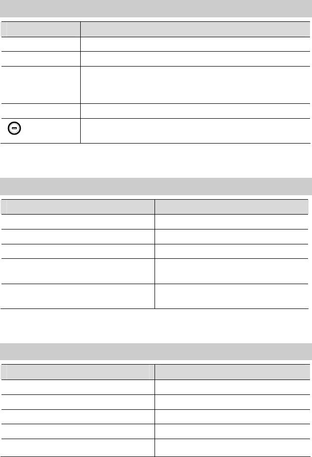
7.1 Indicators
Indicator Status Description
On The HG520c is powered on. POWER
Off The HG520c is powered off.
Blinking The HG520c is being activated.
On The HG520c is activated.
ADSL
Off The HG520c is powered off.
On The WAN connection is successfully established (the
HG520c has obtained an IP address through IPoE and
PPPoE) but no data is being transmitted.
Blinking The WAN connection is successfully established (the
HG520c has obtained an IP address through IPoE and
PPPoE) and data is being transmitted.
INTERNET
Off The HG520c is powered off or the WAN connection is
not yet established.
On The WLAN connection is normal but no data is being
transmitted.
Blinking The WLAN connection is normal and data is being
transmitted.
WLAN
Off The HG520c is powered off, the wireless function is
disabled, or the WLAN module is faulty.
Blinking Data is being transmitted through the Ethernet
interface.
On The Ethernet connection is set up.
LAN
Off The Ethernet connection is not set up.
14
7.2 Interfaces and Buttons
Interface/Button Description
POWER It is used to connect to the power adapter.
LAN It is used to connect to the Ethernet interface on the computer.
RESET You can restore the default settings by pressing this button.
Note: After you restore the default settings, the customized
data will be lost. Therefore, use this function with caution.
ADSL It is used to connect to the MODEM interface on the splitter.
It is the power button on top of the HG520c and is used to
power on or power off the HG520c.
7.3 Default Settings
Parameter Setting
IP address of the LAN interface 192.168.1.1
Subnet mask of the LAN interface 255.255.255.0
DHCP server Enable
User name used to log in to the Web
configuration page admin
Password used to log in to the Web
configuration page admin
7.4 Technical Specifications
Item Specification
Power supply for the HG520c 12 V DC, 0.5 A
Power consumption ≤ 6 W
Ambient temperature for operation 0°C to 40°C
Ambient humidity for operation 5% to 95% (non-condensing)
Dimensions (W × D × H) 164 mm × 142 mm × 49 mm
15

Item Specification
Weight about 300 g
ADSL standards ITU G.992.1 (G.dmt) Annex A
ITU G.994.1 (G.hs)
ANSI T1.413 Issue 2
ADSL2 standard ITU G.992.3 (G.dmt.bis) Annex A
ADSL2+ standard ITU G.992.5 Annex A
Standards
WLAN 802.11b, 802.11g
G.dmt
T1.413
z Maximum downstream rate: 8 Mbit/s
z Maximum upstream rate: 896 kbit/s
Data transmission
G.992.5
(ADSL2+)
z Maximum downstream rate:24 Mbit/s
z Maximum upstream rate: 1024 kbit/s
802.11b 1 Mbit/s, 2 Mbit/s, 5.5 Mbit/s, 11 Mbit/s
WLAN data
transmission 802.11g 6 Mbit/s, 9 Mbit/s, 12 Mbit/s, 18 Mbit/s,
24 Mbit/s, 36 Mbit/s, 48 Mbit/s, 54
Mbit/s
16
HUAWEI TECHNOLOGIES CO., LTD.
Huawei Industrial Base
Bantian, Longgang
Shenzhen 518129
People's Republic of China
www.huawei.com
Part Number: 202139
Federal Communications Commission Statement
This device complies with FCC Rules Part 15. Operation is subject to the following two
conditions:
‧ This device may not cause harmful interference, and
‧ This device must accept any interference received, including interference that may
cause undesired operation.
‧
This equipment has been tested and found to comply with the limits for a class B digital
device, pursuant to Part 15 of the Federal Communications Commission (FCC) rules.
These limits are designed to provide reasonable protection against harmful interference in
a residential installation. This equipment generates, uses, and can radiate radio frequency
energy and, if not installed and used in accordance with the instructions, may cause
harmful interference to radio communications. However, there is no guarantee that
interference will not occur in a particular installation. If this equipment does cause harmful
interference to radio or television reception, which can be determined by turning the
equipment off and on, the user is encouraged to try to correct the interference by one or
more of the following measures:
‧ Reorient or relocate the receiving antenna.
‧ Increase the separation between the equipment and receiver.
‧ Connect the equipment into an outlet on a circuit different from that to which the receiver
is connected.
‧ Consult the dealer or an experienced radio/TV technician for help.
The use of a shielded-type power cord is required in order to meet FCC emission limits and
to prevent interference to the nearby radio and television reception. It is essential that only
the supplied power cord be used. Use only shielded cables to connect I/O devices to this
equipment. You are cautioned that changes or modifications not expressly approved by the
party responsible for compliance could void your authority to operate the equipment.
Note:
Any changes or modifications not expressly approved by the party responsible for
compliance could void the user’s authority to operate this equipment. “The manufacture
declares that this device is limited to Channels 1 through 11 in the 2.4GHz frequency by
specified firmware controlled in the USA.”
RF exposure warning
This equipment complies with FCC radiation exposure limits set forth for an uncontrolled
environment. The antenna(s) used for this transmitter must be installed to provide a separation
distance of at least 20 cm from all persons and must not be co-located or operating in
conjunction with any other antenna or transmitter.