Huawei Technologies HSMPCIAGN01 WIFI Module User Manual MPCI B4322L AGN Product Configuration
Huawei Technologies Co.,Ltd WIFI Module MPCI B4322L AGN Product Configuration
User Manual
MPCI-B4322L-AGN Product Configuration

Contents
1 Configuration....................................................................................................................1-1
1.1 Overview.................................................................................................................1-2
1.1.1 Introduction.............................................................................................................1-2
1.1.2 802.11 Protocol Suite...............................................................................................1-2
1.1.3 Common Terms.......................................................................................................1-3
1.2 Configuring the Basic Attributes of a WLAN............................................................1-3
1.2.1 Establishing the Configuration Task.........................................................................1-3
1.2.2 Setting the Country and Zone Code..........................................................................1-3
1.2.3 (Optional) Setting the Interval for Detecting the Wireless Station..............................1-4
1.3 Configuring a WLAN-BSS Interface........................................................................1-4
1.3.1 Establishing the Configuration Task.........................................................................1-4
1.3.2 Configuring a WLAN-BSS Interface........................................................................1-5
1.4 Configuring a WLAN Service Class.........................................................................1-5
1.4.1 Establishing the Configuration Task.........................................................................1-5
1.4.2 Creating a WLAN Service Class..............................................................................1-6
1.4.3 Configuring the SSID Name.....................................................................................1-6
1.4.4 (Optional) Disabling the SSID Broadcast Function...................................................1-7
1.4.5 (Optional) Setting the Maximum Number of Users Allowed to Access......................1-7
1.4.6 (Optional) Enabling Layer 2 Isolation.......................................................................1-8
1.4.7 (Optional) Configuring MAC Address Filtering........................................................1-8
1.4.8 (Optional) Configuring the QoS Priority...................................................................1-9
1.4.9 Setting the Authentication Mode..............................................................................1-9
1.4.10 Configuring the Encryption Suite............................................................................1-10
1.4.11 (Optional) Configuring 802.1X...............................................................................1-11
1.4.12 Enabling the Service Class......................................................................................1-13
1.4.13 Checking the Configuration.....................................................................................1-14
1.5 Configuring the RF Interface...................................................................................1-14
1.5.1 Establishing the Configuration Task........................................................................1-14
1.5.2 (Optional) Configuring the Basic Attributes of the RF Interface...............................1-14
1.5.3 (Optional) Configuring Fragmentation and Retransmission......................................1-16
1.5.4 (Optional) Configuring 802.11n..............................................................................1-17
1.5.5 (Optional) Configuring WMM................................................................................1-18
1.5.6 Configuring the Binding Between a Service Class and WLAN-BSS Interface..........1-19
1.5.7 Checking the Configuration.....................................................................................1-20
1.6 Configuring Spectrum Management........................................................................1-20
1.6.1 Establishing the Configuration Task........................................................................1-20
1.6.2 (Optinal) Enabling Spectrum Management..............................................................1-20
1.6.3 (Optional) Configuring RF Rate Sets.......................................................................1-21
1.7 Maintenance...........................................................................................................1-22
1.7.1 Debugging..............................................................................................................1-22
1.7.2 Viewing Information...............................................................................................1-23
1.7.3 Clearing Statistics...................................................................................................1-23
1.8 Examples for Configuring a WLAN........................................................................1-24
1.8.1 Example for Configuring a WLAN (Crypto Service Class)......................................1-24
1.8.2 Example for Configuring a WLAN (Plain Service Class).........................................1-26
1.8.3 Example for Configuring a WLAN (802.1X)...........................................................1-28
1.9 FCC Statement of Wireless Module.........................................................................1-32

Figures
Typical networking diagram of a WLAN......................................................................................................1-2
Networking diagram of configuring a WLAN (Crypto service class)............................................................1-24
Networking diagram of configuring a WLAN (Plain service class)...............................................................1-27
Networking diagram of configuring a WLAN (802.1X)...............................................................................1-29

Tables
Commands for checking service class configurations...................................................................................1-14
Commands for checking WMM configurations............................................................................................1-20
Commands for viewing information about wireless stations and the WLAN.................................................1-23
Commands for clearing statistics.................................................................................................................1-23
1 Configuration
About This Chapter
The following table shows the contents of this chapter.
Section Description
1.1Overview This section describes the basic concepts of a WLAN.
1.2Configuring the Basic
Attributes of a WLAN
This section describes how to configure the basic
attributes of a WLAN.
1.3Configuring a WLAN-BSS
Interface
This section describes how to configure a WLAN-BSS
interface.
1.4Configuring a WLAN
Service Class
This section describes how to configure a WLAN service
class.
1.5Configuring the RF
Interface
This section describes how to configure the RF interface.
1.6Configuring Spectrum
Management
This section describes how to configure spectrum
management.
1.7Maintenance This section describes how to maintain a WLAN.
1.8Examples for Configuring
a WLAN
This section provides examples for configuring a WLAN.
1.1 Overview
1.1.1 Introduction
This product is compliant with mini PCI standard Adapter. The Broadcom 802.11b/g/n draft
2.0 SoC technique delivers up to 54Mbps or 300Mbps 11n data rate, the bandwidth support
20MHz and 40MHz for legacy WLAN standard and also fulfilled high throughput data rate
requirement on 11n defined draft 2.0 specification, it is used 2sets of 2.4 Tx / Rx antenna’s
combinations, since the IEEE802.11g is CCK & OFDM modulation scheme and used CCK
modulation to follow backward compatible with IEEE802.11b, up to 54Mbps on single
2.4GHz frequency band.
A Wireless Local Area Network (WLAN) refers to the computer local area network that uses
the wireless channel as the transmission medium. The WLAN is the important supplement
and extension of the wired network and gradually becomes an important part of the computer
network. The WLAN is widely used in the domains where mobile data processing is required
or the layout of physical transmission medium cannot be performed.
l As a new way of broadband access, the WLAN becomes more and more popular and
develops rapidly.
802.11 is currently a common standard for constructing a WLAN because of the simple
technology, stable communication quality, and comparatively larger transmission bandwidth.
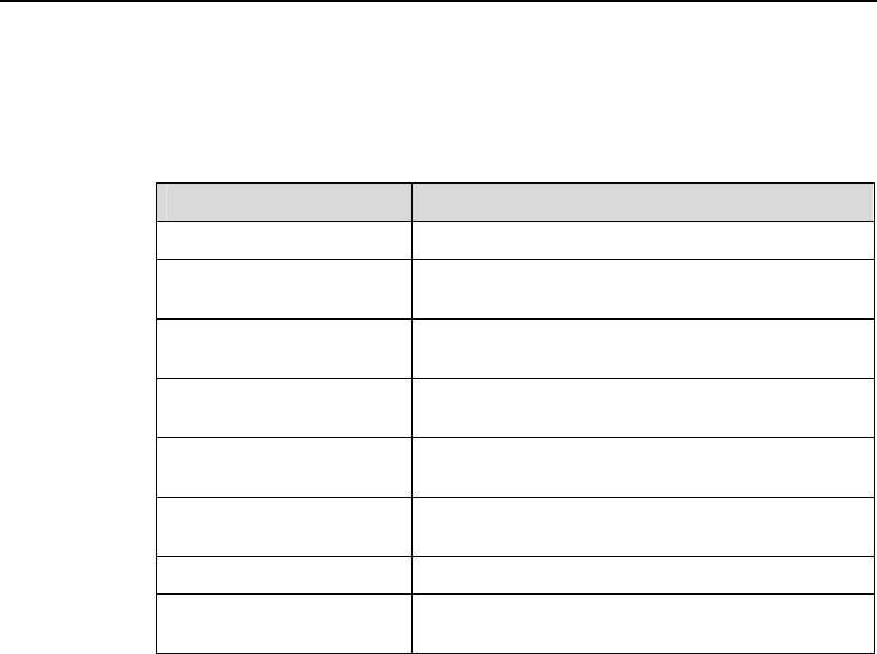
0 shows the typical networking diagram of a WLAN.
Typical networking diagram of a WLAN
1.1.2 802.11 Protocol Suite
With the making and development of IEEE 802.11 wireless network standards, the wireless
network technology becomes more mature and perfect. Currently, the common IEEE 802.11
standards are as follows:
l IEEE 802.11: is the first-version standard made by the IEEE. It defines the MAC layer
and physical layer, the transmission rate as 2 Mbps, and the frequency band as 2.4 GHz.
l IEEE 802.11a: mainly supplements the physical layer, and defines the transmission rate
as 54 Mbps and frequency band as 5 GHz.
l IEEE 802.11b: mainly supplements the physical layer, and defines the transmission rate
as 11 Mbps and frequency band as 2.4 GHz.
l IEEE 802.11e: rectifies the MAC layer to improve the Quality of Service (QoS) and
solves some security problems.
l IEEE 802.11g: is compatible with IEEE 802.11b, and defines the transmission rate as 54
Mbps and frequency band as 2.4 GHz.
l IEEE 802.11i: mainly supplements information about wireless network security.
l IEEE 802.11n: provides the maximum transmission rate of 600 Mbps, and supports the
Multi-Input Multi-Output (MIMO) technology.
1.1.3 Common Terms
l Access Point (AP): provides the bridge function from the wireless station to the LAN
and the frame conversion between wireless and wired modes.
l Basic Service Set (BSS): refers to the range covered by an AP.
l Service Set Identifier (SSID): identifies BSSs. To access the AP, the wireless station must
be configured with the same SSID as that of the AP.
l Wired Equivalent Privacy (WEP): adopts the RC4 symmetric encryption technology at
the link layer. To obtain network resources, the encryption key of the user must be the
same as that of the AP.
l WiFi Protected Access (WPA): is a new technology that inherits basic WEP principles
and corrects some WEP defects. WPA changes the mode of generating the key, improves
the algorithm of generating the key, and changes key modes more frequently to obtain
higher security. Thus WPA effectively solves the problems in WEP encryption.
l WPA2: is the latest version of WPA. It is securer than WPA and more suitable to the
encryption ptotocol with CBC-MAC Protocol (CCMP) in a WLAN.
l 802.1X: is an interface-based network access control protocol. The client connected to
the interface can access network resources only after passing the authentication.
l WiFi Multimedia (WMM): is a wireless QoS protocol that ensures the prior sending
rights for the packets of high priority, thus ensuring the better quality of applications
such as voice and video services on wireless networks.
1.2 Configuring the Basic Attributes of a WLAN
1.2.1 Establishing the Configuration Task
Applicable Environment
A WLAN is to be created.
Data Preparation
To configure the basic attributes of a WLAN, you need the following data:
l Country and zone code
l Interval for detecting the wireless station
1.2.2 Setting the Country and Zone Code
Run:
system-view
The system view is displayed.
Run:
wlan country-zone-code country-zone-code
The country and zone code is set.
The country and zone code determines the attributes of the RF signal, such as the energy level,
number of channels, and channel distribution. Set the correct country and zone code according
to the location where the USG is used.
By default, the country and zone code is US.
----End
1.2.3 (Optional) Setting the Interval for Detecting the Wireless
Station
Run:
system-view
The system view is displayed.
Run:
wlan station idle-timeout interval
The interval for detecting the wireless station by the AP is set.
The AP sends null packets at the interval of idle-timeout interval to detect whether the
associated wireless station is online. If the wireless station is online, it responds to the packets.
If the wireless station does not respond, it indicates that wireless station is offline and the
station is deleted from the network.
By default, the interval for detecting the wireless station by the AP is 60s.
----End
1.3 Configuring a WLAN-BSS Interface
1.3.1 Establishing the Configuration Task
Applicable Environment
A WLAN-BSS interface is to be created before WLAN service class configuration.
Pre-configuration Tasks
Before configuring a WLAN-BSS interface, complete the following tasks:
l Create a VLAN and set the IP address of the Layer 3 interface VLANIF corresponding to
the VLAN.
l Start the Dynamic Host Configuration Protocol (DHCP) server on the VLANIF.
l Add the VLANIF to the security zone and enable the interzone rule to allow packets to
pass through.
Data Preparation
To configure a WLAN-BSS interface, you need the following data:
l WLAN-BSS interface number
l VLAN to which a WLAN-BSS interface is added
1.3.2 Configuring a WLAN-BSS Interface
Run:
system-view
The system view is displayed.
Run:
interface wlan-bss interface-number
A WLAN-BSS interface is created and the interface view is displayed.
(Optional) Run:
description text
The description of the WLAN-BSS interface is configured.
(Optional) Run:
port access vlan vlan-id
The WLAN-BSS interface is added to the specified VLAN.
The VLAN is the one created in section 1.3.1"Establishing the Configuration Task."
A WLAN-BSS interface can be added to only one VLAN.
By default, the WLAN-BSS interface is added to VLAN 1.
----End
1.4 Configuring a WLAN Service Class
1.4.1 Establishing the Configuration Task
Applicable Environment
A WLAN service class is to be created after WLAN-BSS interface configuration. The binding
between a WLAN-BSS interface and WLAN service class indicates that a virtual AP is
successfully created.
Data Preparation
To configure a WLAN service class, you need the following data:
l Number and type of a WLAN service class
l SSID name
l Maximum number of users allowed to access
l Link layer security mode, authentication mode, encryption suite, and key
1.4.2 Creating a WLAN Service Class
Run:
system-view
The system view is displayed.
Run:
wlan service-class service-class-number { plain | crypto }
A WLAN service class is created and the service class view is displayed.
The value of service-class-number ranges from 0 to 1023. A maximum of 64 service classes
are supported. By default, only service class 0 exists.
plain: indicates the plain service class. Data is sent in plain texts.
crypto: indicates the crypto service class. Data is sent in cipher texts.
After creating a service class, you cannot change its type.
After creating a service class, you can run the wlan service-class service-class-number
command to directly access the service class view.
----End
1.4.3 Configuring the SSID Name
Run:
system-view
The system view is displayed.
Run:
wlan service-class service-class-number
The service class view is displayed.
Run:
ssid ssid-name
The SSID name is configured.
The SSID name is a string of 1 to 32 characters. The characters can be all printable ASCII
characters (except the question mark), including the space. The string of the SSID name cannot
start or end with a space.
By default, only service class 0 has its default SSID named gateway.
----End
1.4.4 (Optional) Disabling the SSID Broadcast Function
Run:
system-view
The system view is displayed.
Run:
wlan service-class service-class-number
The service class view is displayed.
Run:
undo broadcast-ssid enable
The SSID broadcast function is disabled, that is, the SSID is hidden.
By default, the SSID broadcast function is enabled.
After the SSID broadcast function is enabled, the USG responds to the broadcast detection
frame and broadcasts its SSID. In this case, any wireless station can find the SSID and access
the network. After the SSID broadcast function is disabled, the USG does not respond to the
broadcast detection frame. In this case, wireless stations cannot find the SSID, which
improves network security.
----End
1.4.5 (Optional) Setting the Maximum Number of Users Allowed
to Access
Run:
system-view
The system view is displayed.
Run:
wlan service-class service-class-number
The service class view is displayed.
Run:
station max-number max-number
The maximum number of users allowed to access is set.
By default, the maximum number of users allowed to access is 64 or 124. When the
encryption suite is TKIP or CCMP, the default value is 64. When the encryption suite is WEP
or not encrypted, the default value is 124.
----End
1.4.6 (Optional) Enabling Layer 2 Isolation
Run:
system-view
The system view is displayed.
Run:
wlan service-class service-class-number
The service class view is displayed.
Run:
station-isolation enable
Layer 2 isolation is enabled.
By default, Layer 2 isolation is disabled.
If Layer 2 isolation is enabled, the two wireless stations on the same AP cannot access each
other.
----End
1.4.7 (Optional) Configuring MAC Address Filtering
After blacklist-based MAC address filtering is configured, the wireless stations whose MAC
addresses are in the blacklist are denied to access. Other wireless stations, however, are not
restricted. After whitelist-based MAC address filtering is configured, only the wireless
stations whose MAC addresses are in the whitelist are allowed to access. Other wireless
stations, however, cannot access.
Run:
system-view
The system view is displayed.
Run:
wlan service-class service-class-number
The service class view is displayed.
Run:
mac-filter { blacklist | whitelist } mac-address
The MAC address blacklist or whitelist is configured.
A maximum of 64 MAC addresses (64 for the blacklist and whitelist respectively) are
supported in a service class. A maximum of 256 MAC addresses (256 for the blacklist and
whitelist respectively) are supported on an USG.
Run:
mac-filter { blacklist | whitelist } enable
MAC address filtering is enabled.
By default, MAC address filtering is disabled.
----End
1.4.8 (Optional) Configuring the QoS Priority
Run:
system-view
The system view is displayed.
Run:
wlan service-class service-class-number
The service class view is displayed.
Run:
qos-priority mapping-policy { normal | cos | tos }
The QoS priority policy of forwarding packets from the wired network to the wireless
network is configured.
By default, the QoS priority policy is tos.
Run:
qos-priority mapping-table { dscp-lp | dot1p-lp }
The QoS mapping table view is displayed.
Run:
previous-priority pre-value-list mapped-priority mapped-value
QoS priority mapping is modified.
----End
1.4.9 Setting the Authentication Mode
The configuration described in this section is supported by only the service class of the crypto
type.
The USG supports two authentication modes: Open System Authentication and Shared Key
Authentication.
In Open System Authentication, the None, WPA, WPA-PSK, WPA2, WPA2-PSK, WPA-
WPA2 and WPA-WPA2-PSK modes are supported. Shared Key Authentication is an early
wireless authentication scheme that is used for the compatibility with the USGs of early
versions. In Shared Key Authentication, the WEP mode must be adopted.
Run:
system-view
The system view is displayed.
Run:
wlan service-class service-class-number
The service class view is displayed.
Run:
security-mode { open-system | shared-key }
The link layer security mode is set.
By default, the link layer security mode is open-system.
Run:
authentication-mode { none | wpa | wpa-psk | wpa-wpa2 | wpa-wpa2-psk | wpa2 | wpa2-
psk }
The authentication mode is set.
This command is valid only when the link layer security mode is open-system.
By default, the authentication mode is none.
----End
1.4.10 Configuring the Encryption Suite
The configuration described in this section is supported by only the service class of the crypto
type.
Run:
system-view
The system view is displayed.
Run:
wlan service-class service-class-number
The service class view is displayed.
Run:
encryption-suite { ccmp | tkip | wep }
The encryption suite used during frame encryption is configured.
By default, the WEP encryption suite is used.
In Shared Key Authentication, only the WEP encryption suite is supported. In Open System
Authentication, the supported encryption suites vary according to authentication-mode:
l When authentication-mode is set to none, only the WEP encryption suite is supported.
l When authentication-mode is set to wpa2 or wpa2-psk, only the CCMP encryption
suite is supported.
l When authentication-mode is set to other modes, the TKIP and CCMP encryption
suites are supported.
Run:
wep key key-id { wep40 | wep104 } { pass-phrase | raw-key } key
The WEP key is configured.
This command is valid only when the WEP encryption suite is adopted.
Run:
wep current-key-id key-id
The ID of the used WEP key is set.
This command is valid only when the WEP encryption suite is adopted.
By default, WEP key 1 is valid.
Run:
pre-shared-key { pass-phrase | raw-key } key
The pre-shared key is configured.
This command is valid only when the authentication mode is WPA-PSK, WPA2-PSK or
WPA-WPA2-PSK.
By default, there is no pre-shared key.
----End
1.4.11 (Optional) Configuring 802.1X
This configuration is available only when the authentication mode is WPA, WPA2 or WPA-
WPA2.
Run:
system-view
The system view is displayed.
Run:
wlan service-class service-class-number
The service class view is displayed.
(Optional) Run:
dot1x domain-1x domain-name
An 802.1X domain is created.
By default, an 802.1X domain named dot1x is already created.
Run:
dot1x quiet-period enable
The 802.1X quiet function is enabled.
By default, the 802.1X quiet function is disabled.
After a user fails to pass 802.1X authentication, the USG enters the quiet period. During the
quiet period, the USG does not process the 802.1X authentication packets sent by the user.
Run:
quit
The system view is returned.
To configure Remote Authentication Dial-In User Service (RADIUS), do as follows:
Run:
radius-server template template-name
A RADIUS server template is created and the RADIUS server template view is
displayed.
Run:
radius-server authentication ip-address port
The primary RADIUS authentication server is configured.
(Optional) Run:
radius-server authentication ip-address port secondary
The secondary RADIUS authentication server is configured.
Run:
radius-server type standard
The RADIUS protocol is configured.
In 802.1X authentication, only the standard protocol is supported.
Run:
radius-server shared-key key-string
The key of the RADIUS server is configured.
Run:
undo radius-server user-name domain-included
The transmission of the user name without the domain name to the RADIUS server is
configured.
Run:
quit
The system view is returned.
To configure AAA, do as follows:
Run:
aaa
The AAA view is displayed.
Run:
authentication-scheme scheme-name
An authentication scheme is created and the authentication scheme view is displayed.
The authentication scheme that is being referred to cannot be deleted.
Run:
authentication-mode radius
The authentication mode is set to RADIUS.
Run:
quit
The AAA view is returned.

Run:
domain domain-name
A domain is created and the domain view is displayed.
The created domain is the 802.1X domain.
Run:
radius-server template-name
The RADIUS server template of the current domain is configured.
Run:
authentication-scheme scheme-name
The authentication scheme of the current domain is configured.
----End
For the detailed configuration of AAA and RADIUS, see section 01-04 "Authentication and
Authorization Configuration" in the Configuration Guide Security Defense Volume.
1.4.12 Enabling the Service Class
Run:
system-view
The system view is displayed.
Run:
wlan service-class service-class-number
The service class view is displayed.
Run:
service-class enable
The WLAN service class is enabled.
By default, only service class 0 is enabled.
----End

1.4.13 Checking the Configuration
0 shows the commands for checking service class configurations.
Commands for checking service class configurations
Action Command View
Checking the QoS priority
mapping table
display wlan qos-priority mapping-
table { all | dot1p-lp | dscp-lp }
service-class service-class-number
All views
Checking the blacklist or
whitelist of the specified
service class
display wlan mac-filter { whitelist |
blacklist } service-class-number
All views
Checking information
about the specified service
class
display wlan service-class [ service-
class-number ]
All views
1.5 Configuring the RF Interface
1.5.1 Establishing the Configuration Task
Applicable Environment
The USG has only one RF interface, which supports 16 virtual APs at the same time. The
configurations on the RF interface are applicable to all APs.
Data Preparation
To configure the RF interface, you need the following data:
l Basic attributes of the RF interface, including the working channel, maximum
transmission power, and RF type
l Fragment threshold and maximum retransmission times for long or short frames
l 802.11n parameters
l WMM parameters
l Bound service class and WLAN-BSS interface
1.5.2 (Optional) Configuring the Basic Attributes of the RF
Interface
Run:
system-view
The system view is displayed.
Run:
interface wlan-rf 4/0/0
The RF interface view is displayed.
Run:
shutdown
The RF interface is shut down.
Some RF interface parameters need to be set when the RF interface is shut down. It is
recommended that you shut down the RF interface before modifying interface configurations.
By default, the RF interface state is open.
Run:
radio-type radio-type
The RF type used by the RF interface is set.
By default, the RF type is dot11gn.
The values of radio-type are: dot11a (802.11a type and 5 GHz frequency band), dot11an
(802.11n type, 5 GHz frequency band, and compatible with 802.11a), dot11b (802.11b type
and 2.4 GHz frequency band), dot11g (802.11g type, 2.4 GHz frequency band, and
compatible with 802.11b), dot11gn (802.11n type, 2.4 GHz frequency band, and compatible
with 802.11g and 802.11b).
Run:
channel { auto | channel }
The working channel of the RF interface is set.
The channel number varies according to the country and zone code and the RF type.
By default, the USG automatically determines the channel number according to the channel
scanning result.
Run:
max-power max-power
The maximum transmission power of the RF interface is set.
By default, the maximum transmission power of the RF interface is 17 dbm.
Run:
dtim dtim
The Delivery Traffic Indication Message (DTIM) period of the beacon frame is set.
By default, the DTIM period of the beacon frame is 3.
----End
1.5.3 (Optional) Configuring Fragmentation and Retransmission
Run:
system-view
The system view is displayed.
Run:
interface wlan-rf 4/0/0
The RF interface view is displayed.
Run:
shutdown
The RF interface is shut down.
Some RF interface parameters need to be set when the RF interface is shut down. It is
recommended that you shut down the RF interface before modifying interface configurations.
By default, the RF interface state is open.
Run:
fragment-threshold size
The fragment threshold for packets is set.
When the actual size of a packet exceeds the fragment threshold, the packet is transmitted in
fragments.
By default, the fragment threshold for packets is 2346 bytes.
Run:
rts threshold size
The threshold of the frame length required for starting the Request To Send (RTS) mechanism
is set.
When the frame length exceeds the threshold, the USG starts the RTS mechanism.
By default, the threshold of the frame length required for starting the RTS mechanism is 2347
bytes.
Run:
long-retry threshold count
The maximum retransmission times for long frames (the frame length exceeds the threshold)
is set.
By default, the maximum retransmission times for long frames is 4.
Run:
short-retry threshold count
The maximum retransmission times for short frames (the frame length does not exceed the
threshold) is set.
By default, the maximum retransmission times for short frames is 7.
----End
1.5.4 (Optional) Configuring 802.11n
The configuration described in this section is valid only when the RF interface type is 802.11n.
For the setting of the RF interface type, see section 1.5.2 "(Optional) Configuring the Basic
Attributes of the RF Interface."
802.11n supports both the 2.4 GHz and 5 GHz frequency bands, providing faster access rate
for users. 802.11n makes the following improvements:
l Forms a 40 MHz bandwidth by binding two 20 MHz bandwidths. This improves the
bandwidth.
l Provides MAC Protocol Data Unit (MPDU) convergence. That is, multiple MPDUs are
converged to an A-MPDU and only the physical layer head is reserved. This improves
network throughput.
l Provides MAC Service Data Unit (MSDU) convergence. That is, multiple MSDUs are
converged to an A-MSDU for sending. The principle of MSDU convergence is similar to
that of MPDU convergence.
l Provides the short Guard Interval (GI). This reduces the GI and improves the packet
forwarding rate.
Run:
system-view
The system view is displayed.
Run:
interface wlan-rf 4/0/0
The RF interface view is displayed.
Run:
shutdown
The RF interface is shut down.
Some RF interface parameters need to be set when the RF interface is shut down. It is
recommended that you shut down the RF interface before modifying interface configurations.
By default, the RF interface state is open.
Run:
channel bandwidth { 20 | 40 }
The bandwidth (channel) of the RF interface is set.
By default, the bandwidth is 40 MHz when the RF type is dot11an; the bandwidth is 20 MHz
when the RF type is dot11a, dot11b, dot11g, or dot11gn.
Run:
short-gi enable
The short GI function is enabled.
By default, the short GI function is disabled.
Run:
a-mpdu enable
MPDU convergence is enabled.
This command cannot be used together with the a-msdu enable command.
By default, MPDU convergence is enabled.
Run:
a-msdu enable
MSDU convergence is enabled.
This command cannot be used together with the a-mpdu enable command.
By default, MSDU convergence is disabled.
----End
1.5.5 (Optional) Configuring WMM
The traditional WLAN treats all data equally. When traffic exceeds the available bandwidth,
packets are all discarded regardless of priorities, which brings difficulties in forwarding the
packets of high priority. WMM provides four priority queues from high priority to low
priority: AC-VO (voice flow), AC-VI (video flow), AC-BE (best effort flow), and AC-BK
(background flow). When congestion occurs, WMM ensures that the packets in the high
priority queue are forwarded first.
WMM defines a set of enhanced distribution channel access (EDCA) parameters for each
priority queue, including AIFSN, ECWmin, ECWmax, and TXOPLimit.
Run:
system-view
The system view is displayed.
Run:
interface wlan-rf 4/0/0
The RF interface view is displayed.
Run:
shutdown
The RF interface is shut down.
Some RF interface parameters need to be set when the RF interface is shut down. It is
recommended that you shut down the RF interface before modifying interface configurations.
By default, the RF interface state is open.
Run:
wmm enable
WMM is enabled.
By default, WMM is enabled.
WMM is applicable to wireless multimedia services, such as voice and video services.
Run:
wmm edca { ap | station } { ac-vo | ac-vi | ac-be | ac-bk } { aifsn aifsn-value |
ecwmin ecwmin-value | ecwmax ecwmax-value | txop txop-value }
EDCA parameters are set.
It is recommended that the default value be adopted. If the value of the parameter needs to be
changed, it is recommended that the following conditions be complied with:
l aifsn (ac-vo) <=aifsn (ac-vi) <=aifsn (ac-be) <=aifsn (ac-bk)
l ecwmin (ac-vo) <=ecwmin (ac-vi) <=ecwmin (ac-be) <=ecwmin (ac-bk)
l ecwmax (ac-vo) <=ecwmax (ac-vi) <=ecwmax (ac-be) <=ecwmax (ac-bk)
Run:
wmm u-apsd enable
Unscheduled automatic power-saving delivery (U-APSD) is enabled.
U-APSD is a new type of power-saving mode defined by WMM. It can further improve the
power-saving capability of wireless stations.
By default, U-APSD is enabled.
Run:
wmm ap noack
The no-acknowledgement mode of the AP is enabled.
In no-acknowledgement mode, the USG does not use ACK packets to acknowledge the
received packets. This effectively improves the transmission efficiency but may cause packet
loss. Thus, the no-acknowledgement mode is not recommended when signal interference
exists.
By default, the AP is in acknowledgement mode.
----End
1.5.6 Configuring the Binding Between a Service Class and
WLAN-BSS Interface
The binding between a service class and WLAN-BSS interface indicates that a virtual AP is
successfully configured.
Run:
system-view
The system view is displayed.
Run:
interface wlan-rf 4/0/0
The RF interface view is displayed.
Run:
bind service-class service-class-number interface wlan-bss wlan-bss-number
A service class and WLAN-BSS interface are bound.
By default, service class 0 and WLAN-BSS interface 0 are bound, and cannot be unbound.
Run:
undo shutdown
The RF interface state turn into open.
----End
1.5.7 Checking the Configuration
0 shows the commands for checking WMM configurations.
Commands for checking WMM configurations
Action Command View
Checking EDCA
parameters
display wlan wmm edca { ap | station } All views
1.6 Configuring Spectrum Management
1.6.1 Establishing the Configuration Task
Applicable Environment
Spectrum management is to be applied on a WLAN.
Data Preparation
To configure spectrum management, you need the following data:
l RF power constraint
l RF rate set
1.6.2 (Optinal) Enabling Spectrum Management
Run:
system-view
The system view is displayed.
Run:
wlan srm
The spectrum management view is displayed.
Run:
spectrum-management enable
Spectrum management is enabled.
This function and the automatic channel selection function are mutually exclusive. After
spectrum management is enabled, the automatic channel selection function does not take
effect.
After the running of this command, the AP controls the transmission power and scans the
radar signals around to avoid radar signal interference. Also, the AP broadcasts the power
capability and power constraint of the AP. All the wireless stations under the AP should
comply with the power constraint broadcast by the AP.
By default, spectrum management is disabled.
Run:
power-constraint power-constraint
The RF power constraint is set.
This command is valid only when the spectrum-management enable command is enabled.
When spectrum management is enabled, the RF power constraint is broadcast in the beacon
frame.
By default, the RF power constraint is not set.
----End
1.6.3 (Optional) Configuring RF Rate Sets
Multiple wireless stations may access the AP and the rate sets supported by these wireless
stations may be different. As a result, a rate supported by all wireless stations is required for
sending broadcast and multicast packets. Also, a rate supported by wireless stations for
sending unicast packets should be selected.
Rate sets vary according to different country and zone codes.
Run:
system-view
The system view is displayed.
Run:
wlan srm
The spectrum management view is displayed.
Run:
dot11g protection enable
The function of 802.11g protection is enabled.
Protocol 802.11g is compatible with protocol 802.11b.When the AP uses 802.11g and both
802.11g and 802.11b wireless stations exist (in composite networking mode), the 802.11g
protection function needs to be enabled to ensure that various wireless stations can
communicate normally.
By default, the function of 802.11g protection is disabled.
Run:
{ dot11a | dot11b | dot11g } mandatory-rate mandatory-rate
Basic RF rate sets are set.
By default, the basic rate set of dot11a consists of 6, 9, 12, and 24; the basic rate set of
dot11b consists of 1 and 2; the basic rate set of dot11g consists of 1, 2, 5.5, and 11, in Mbps.
Run:
{ dot11a | dot11b | dot11g } supported-rate supported-rate
Supported RF rate sets are set.
By default, the supported rate set of dot11a consists of 18, 36, 48, and 54; the supported rate
set of dot11b consists of 5.5 and 11; the supported rate set of dot11g consists of 6, 9, 12, 18,
24, 36, 48, and 54, in Mbps.
----End
1.7 Maintenance
1.7.1 Debugging
Enabling the debugging function affects system performance. Therefore, after debugging, run
the undo debugging all command to immediately disable the debugging function.
When a running fault occurs, run the debugging command in the user view to view the
debugging information, and locate and analyze the fault.
Action Command
Enabling the function of debugging
a WLAN
debugging wlan { all | error | module { a-mpdu |
a-msdu | assoc | dfs | forward | mbss | phy |
power-manager | radar | rate | sec } }
1.7.2 Viewing Information
0 shows the commands for viewing information about wireless stations and the WLAN.
Commands for viewing information about wireless stations and the WLAN
Action Command View
Viewing the MAC address of
the associated wireless
station
display wlan station association [ bss-
number ]
All views
Viewing security statistics display wlan security { session | statistics }
bss-number
All views
Viewing the status of the
specified wireless station
display wlan station information mac-
address
All views
Viewing statistics on
wireless stations
display wlan statistics station { all | mac-
address mac-address }
All views
Viewing WMM statistics display wlan wmm statistics All views
Viewing information about
the RF interface
display interface wlan-rf [ rf-number ] All views
Viewing information about
the WLAN-BSS interface
display interface wlan-bss [ bss-number ] All views
1.7.3 Clearing Statistics
0 shows the commands for clearing statistics in the user view.
Commands for clearing statistics
Action Command
Disconnecting from the specified
wireless station
reset wlan station { all | mac-address mac-
address }
Clearing statistics on wireless
stations
reset wlan statistics station { all | mac-address
mac-address }
Clearing WMM statistics reset wlan wmm statistics
Clearing statistics on the RF
interface
reset counters interface [ wlan-rf [ rf-number ] ]
Clearing statistics on the WLAN-
BSS interface
reset counters interface [ wlan-bss [ bss-
number ] ]
Clearing WLAN security statistics reset wlan security statistics { all | bss-number }
1.8 Examples for Configuring a WLAN
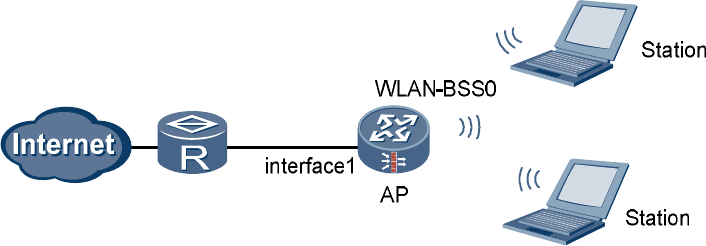
1.8.1 Example for Configuring a WLAN (Crypto Service Class)
Networking Requirements
l The AP is connected to the router through Ethernet 0/0/0 (already added to the Untrust
zone).
l The fixed IP address of Ethernet 0/0/0 is 202.169.10.1/24 and the IP address of the router
is 202.169.10.2/24.
l The IP address of the DNS Server is 205.1.1.10. You can obtain it from the operator.
l The IP addresses of the two stations are 192.168.1.2/24 and 192.168.1.3/24.
l The stations use wireless network cards to connect to the AP (USG), with the SSID of
WLAN100.
l Disabling the default AP (service-class 0).
l The authentication mode is WPA-WPA2-PSK, the pre-shared key is abcdefgh, and the
CCMP and TKIP encryption suite is adopted.
The stations can access the Internet in wireless mode through the configuration of a WLAN.
Networking Diagram
Networking diagram of configuring a WLAN (Crypto service class)
interface1 Ethernet 0/0/0: 202.169.10.1/24
Configuration Procedure
Perform basic configurations.
# Create VLANIF 2.
<USG> system-view
[USG] vlan 2
[USG-vlan2] quit
[USG] interface Vlanif 2
[USG-Vlanif2] ip address 192.168.1.1 255.255.255.0
[USG-Vlanif2] quit
# Access the Trust zone view.
[USG] firewall zone trust
# Add VLANIF 2 to the Trust zone.
[USG-zone-trust] add interface Vlanif 2
[USG-zone-trust] quit
# Configure the interzone packet filtering rule.
[USG] firewall packet-filter default permit all
# Configure the country and zone code to ES (Spain).
[USG] wlan country-zone-code ES
Configure a WLAN-BSS interface.
# Create a WLAN-BSS interface.
[USG] interface wlan-bss 2
# Add the WLAN-BSS interface to VLAN 2.
[USG-Wlan-Bss2] port access vlan 2
[USG-Wlan-Bss2] quit
Configure a service class.
# Create a service class.
[USG] wlan service-class 2 crypto
# Set the SSID.
[USG-wlan-sc-2] ssid WLAN100
# Set the authentication mode.
[USG-wlan-sc-2] authentication-method wpa-wpa2-psk
# Configure the encryption suite for data frames.
[USG-wlan-sc-2] encryption-suite ccmp
[USG-wlan-sc-2] encryption-suite tkip
# Configure the pre-shared key.
[USG-wlan-sc-2] pre-shared-key pass-phrase abcdefgh
# Enable the service class.
[USG-wlan-sc-2] service-class enable
[USG-wlan-sc-2] quit
# Disabling the default AP (service-class 0).
[USG] wlan service-class 0
[USG-wlan-sc-0] undo service-class enable
[USG-wlan-sc-0] quit
Configure the RF interface.
# Set the RF type used by the RF interface to dot11gn.
[USG] interface wlan-rf 4/0/0
[USG-Wlan-rf4/0/0] shutdown
[USG-Wlan-rf4/0/0] radio-type dot11gn
[USG-Wlan-rf4/0/0] undo shutdown
# Configure the binding between the service class and WLAN-BSS interface.
[USG-Wlan-rf4/0/0] bind service-class 2 interface wlan-bss 2
[USG-Wlan-rf4/0/0] quit
Configure NAT.
# Configure the ACL rule.
[USG] acl 2001
[USG-acl-basic-2001] rule 1 permit source 192.168.1.0 0.0.0.255
[USG-acl-basic-2001] quit
# Configure the interzone packet filtering rule for the Trust zone and Untrust zone.
[USG] firewall interzone trust untrust
[USG-interzone-trust-untrust] packet-filter 2001 outbound
# Configure NAT.
[USG-interzone-trust-untrust] nat outbound 2001 interface Ethernet0/0/0
[USG-interzone-trust-untrust] quit
# Configure the default route.
[USG] ip route-static 0.0.0.0 0.0.0.0 202.169.10.2
Configure the wireless network cards on the client.
l Manually set the IP addresses of the wireless network cards to 192.168.1.2/24 and
192.168.1.3/24.
l Manually set the IP address of the DNS Server to 205.1.1.10.
l The SSID, encryption mode, authentication mode, and pre-shared key on the wireless
network cards should be consistent with those on the USG.
----End
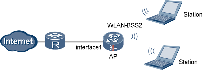
1.8.2 Example for Configuring a WLAN (Plain Service Class)
Networking Requirements
l The AP is connected to the router through Ethernet 0/0/0 (already added to the Untrust
zone).
l The fixed IP address of Ethernet 0/0/0 is 202.169.10.1/24 and the IP address of the router
is 202.169.10.2/24.
l The IP address of the DNS Server is 205.1.1.10. You can obtain it from the operator.
l The two stations automatically obtain IP addresses through DHCP.
l The stations use wireless network cards to connect to the AP (USG), with the SSID of
WLAN100.
The stations can access the Internet in wireless mode through the configuration of a WLAN.
Networking Diagram
Networking diagram of configuring a WLAN (Plain service class)
interface1 Ethernet 0/0/0: 202.169.10.1/24
Configuration Procedure
Perform basic configurations.
# Create VLANIF 2.
<USG> system-view
[USG] vlan 2
[USG-vlan2] quit
[USG] interface Vlanif 2
[USG-Vlanif2] ip address 192.168.1.1 255.255.255.0
[USG-Vlanif2] dhcp select interface
[USG-Vlanif2] dhcp server dns-list 205.1.1.10
[USG-Vlanif2] quit
# Access the Trust zone view.
[USG] firewall zone trust
# Add VLANIF 2 to the Trust zone.
[USG-zone-trust] add interface Vlanif 2
[USG-zone-trust] quit
# Configure the interzone packet filtering rule.
[USG] firewall packet-filter default permit all
# Configure the country and zone code to ES (Spain).
[USG] wlan country-zone-code ES
Configure a WLAN-BSS interface.
# Enter the WLAN-BSS interface view.
[USG] interface wlan-bss 0
# Add the WLAN-BSS interface to VLAN 2.
[USG-Wlan-Bss0] port access vlan 2
[USG-Wlan-Bss0] quit
Configure a service class.
# Create a service class.
[USG] wlan service-class 0
# Set the SSID.
[USG-wlan-sc-0] ssid WLAN100
# Enable the service class.
[USG-wlan-sc-0] service-class enable
[USG-wlan-sc-0] quit
Configure the binding between the service class and WLAN-BSS interface.
[USG] interface wlan-rf 4/0/0
[USG-Wlan-rf4/0/0] bind service-class 0 interface wlan-bss 0
[USG-Wlan-rf4/0/0] quit
Configure NAT.
# Configure the ACL rule.
[USG] acl 2001
[USG-acl-basic-2001] rule 1 permit source 192.168.1.0 0.0.0.255
[USG-acl-basic-2001] quit
# Configure the interzone packet filtering rule for the Trust zone and Untrust zone.
[USG] firewall interzone trust untrust
[USG-interzone-trust-untrust] packet-filter 2001 outbound
# Configure NAT.
[USG-interzone-trust-untrust] nat outbound 2001 interface Ethernet0/0/0
[USG-interzone-trust-untrust] quit
# Configure the default route.
[USG] ip route-static 0.0.0.0 0.0.0.0 202.169.10.2
Configure the wireless network cards on the client.
l Configure the wireless network cards to automatically obtain IP addresses.
l Configure the wireless network cards to automatically obtain DNS Server.
l The SSID, encryption mode, and authentication mode on the wireless network cards
should be consistent with those on the USG.
----End
1.8.3 Example for Configuring a WLAN (802.1X)
Networking Requirements
l The AP is connected to the router through Ethernet 0/0/0 (already added to the Untrust
zone).
l The fixed IP address of Ethernet 0/0/0 is 202.169.10.1/24 and the IP address of the router
is 202.169.10.2/24.
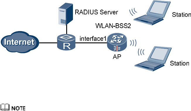
l The IP address of the DNS Server is 205.1.1.10. You can obtain it from the operator.
l The two stations automatically obtain IP addresses through DHCP.
l The stations use wireless network cards to connect to the AP (USG), with the SSID of
WLAN100.
l Disabling the default AP (service-class 0).
l 802.1X authentication is enabled. The IP address of the RADIUS server is
202.169.10.100/24 and the key is hello.
The stations can access the Internet in wireless mode through the configuration of a WLAN.
Networking Diagram
Networking diagram of configuring a WLAN (802.1X)
interface1 Ethernet 0/0/0: 202.169.10.1/24
Configuration Procedure
Select WPA, WPA2 or WPA-WPA2 for the authentication mode when configuring 802.1X.
Perform basic configurations.
# Create VLANIF 2.
<USG> system-view
[USG] vlan 2
[USG-vlan2] quit
[USG] interface Vlanif 2
[USG-Vlanif2] ip address 192.168.1.1 255.255.255.0
[USG-Vlanif2] dhcp select interface
[USG-Vlanif2] dhcp server dns-list 205.1.1.10
[USG-Vlanif2] quit
# Access the Trust zone view.
[USG] firewall zone trust
# Add VLANIF 2 to the Trust zone.
[USG-zone-trust] add interface Vlanif 2
[USG-zone-trust] quit
# Configure the interzone packet filtering rule.
[USG] firewall packet-filter default permit all
# Configure the country and zone code to ES (Spain).
[USG] wlan country-zone-code ES
Configure a WLAN-BSS interface.
# Create a WLAN-BSS interface.
[USG] interface wlan-bss 2
# Add the WLAN-BSS interface to VLAN 2.
[USG-Wlan-Bss2] port access vlan 2
[USG-Wlan-Bss2] quit
Configure a service class.
# Create a service class.
[USG] wlan service-class 2 crypto
# Set the SSID.
[USG-wlan-sc-2] ssid WLAN100
# Set the authentication mode.
[USG-wlan-sc-2] authentication-method wpa2
# Create an 802.1X domain.
[USG-wlan-sc-2] dot1x domain-1x abc
# Enable the service class.
[USG-wlan-sc-2] service-class enable
[USG-wlan-sc-2] quit
# Disabling the default AP (service-class 0).
[USG] wlan service-class 0
[USG-wlan-sc-0] undo service-class enable
[USG-wlan-sc-0] quit
Configure the binding between the service class and WLAN-BSS interface.
[USG] interface wlan-rf 4/0/0
[USG-Wlan-rf4/0/0] bind service-class 2 interface wlan-bss 2
[USG-Wlan-rf4/0/0] quit
Configure NAT.
# Configure the ACL rule.
[USG] acl 2001
[USG-acl-basic-2001] rule 1 permit source 192.168.1.0 0.0.0.255
[USG-acl-basic-2001] quit
# Configure the interzone packet filtering rule for the Trust zone and Untrust zone.
[USG] firewall interzone trust untrust
[USG-interzone-trust-untrust] packet-filter 2001 outbound
# Configure NAT.
[USG-interzone-trust-untrust] nat outbound 2001 interface Ethernet0/0/0
[USG-interzone-trust-untrust] quit
# Configure the default route.
[USG] ip route-static 0.0.0.0 0.0.0.0 202.169.10.2
Configure RADIUS.
# Create a RADIUS server template.
[USG] radius-server template test1
# Configure the RADIUS authentication server.
[USG-radius-test1] radius-server authentication 202.169.10.100 1812
# Configure the RADIUS protocol.
[USG-radius-test1] radius-server type standard
# Configure the key of the RADIUS server.
[USG-radius-test1] radius-server shared-key hello
[USG-radius-test1] undo radius-server user-name domain-included
[USG-radius-test1] quit
Configure AAA.
# Access the AAA view.
[USG] aaa
# Configure the RADIUS authentication scheme.
[USG-aaa] authentication-scheme mywlan
[USG-aaa-authen-mywlan] authentication-mode radius
[USG-aaa-authen-mywlan] quit
# Create a domain.
[USG-aaa] domain abc
# Configure the RADIUS server template of the current domain.
[USG-aaa-domain-abc] radius-server test1
# Configure the authentication scheme of the domain.
[USG-aaa-domain-abc] authentication-scheme mywlan
Configure the wireless network cards on the client.
l Configure the wireless network cards to automatically obtain IP addresses.
l Configure the wireless network cards to automatically obtain DNS Server.
l The SSID and authentication mode on the wireless network cards should be consistent
with those on the USG.
l The user name and password for 802.1X authentication should be consistent with those
on the RADIUS server.
----End
1.9 FCC Statement of Wireless Module
15.19
NOTICE:
This device complies with Part 15 of the FCC Rules. Operation is subject to the following two
conditions:
(1) This device may not cause harmful interference, and 2) This device must accept any
interference received, including interference that may cause undesired operation.
15.21
NOTICE:
Changes or modifications made to this device not expressly approved by Huawei
Technologies Co., Ltd. may void the FCC authorization to operate this device.
15.105
NOTE:
This device has been tested and found to comply with the limits for a Class B digital device,
pursuant to Part 15 of the FCC Rules. These limits are designed to provide reasonable
protection against harmful interference in a residential installation. This device generates uses
and can radiate radio frequency energy and, if not installed and used in accordance with the
instructions, may cause harmful interference to radio communications. However, there is no
guarantee that interference will not occur in a particular installation. If this device does cause
harmful interference to radio or television reception, which can be determined by connecting
or disconnecting the device to a PC, the user is encouraged to try to correct the interference by
adopting one or more of the following measures:
Reorient or relocate the receiving antenna.
Increase the distance between the device and the receiver.
Connect the device to an outlet on a circuit different from that to which the receiver is
connected.
Consult the dealer or an experienced radio or TV technician for help.
FCC Caution: Any changes or modifications not expressly approved by the party responsible
for compliance could void the user's authority to operate this device.
This device is intended for OEM integrators only.
Host system must be labeled with "Contains FCC ID: QISHSMPCIAGN01", FCC ID
displayed on label.
Antenna use:
The antenna(s) used for this transmitter must be installed to provide a separation distance of at
least 20 cm from all persons.