Huawei Technologies ME209U-526 LTE Module User Manual English
Huawei Technologies Co.,Ltd LTE Module English
Contents
- 1. UserManual.pdf
- 2. UserManual_SafetyInstructions.pdf
- 3. InstallationInstructions.pdf
- 4. Safety Information.pdf
InstallationInstructions.pdf

Copyright © Huawei Technologies Co., Ltd. 2013.
All rights reserved.
No part of this document may be reproduced or transmitted in any form or by any means without
prior written consent of Huawei Technologies Co., Ltd.
The product described in this manual may include copyrighted software of Huawei Technologies Co.,
Ltd and possible licensors. Customers shall not in any manner reproduce, distribute, modify,
decompile, disassemble, decrypt, extract, reverse engineer, lease, assign, or sublicense the said
software, unless such restrictions are prohibited by applicable laws or such actions are approved by
respective copyright holders under licenses.
Trademarks and Permissions
, , and are trademarks or registered trademarks of Huawei Technologies
Co., Ltd.
Other trademarks, product, service and company names mentioned are the property of their
respective owners.
Notice
Some features of the product and its accessories described herein rely on the software installed,
capacities and settings of local network, and may not be activated or may be limited by local
network operators or network service providers, thus the descriptions herein may not exactly match
the product or its accessories you purchase.
Huawei Technologies Co., Ltd reserves the right to change or modify any information or
specifications contained in this manual without prior notice or obligation.
NO WARRANTY
THE CONTENTS OF THIS MANUAL ARE PROVIDED “AS IS”. EXCEPT AS REQUIRED BY APPLICABLE
LAWS, NO WARRANTIES OF ANY KIND, EITHER EXPRESS OR IMPLIED, INCLUDING BUT NOT
LIMITED TO, THE IMPLIED WARRANTIES OF MERCHANTABILITY AND FITNESS FOR A PARTICULAR
PURPOSE, ARE MADE IN RELATION TO THE ACCURACY, RELIABILITY OR CONTENTS OF THIS
MANUAL.
TO THE MAXIMUM EXTENT PERMITTED BY APPLICABLE LAW, IN NO CASE SHALL HUAWEI
TECHNOLOGIES CO., LTD BE LIABLE FOR ANY SPECIAL, INCIDENTAL, INDIRECT, OR
CONSEQUENTIAL DAMAGES, OR LOST PROFITS, BUSINESS, REVENUE, DATA, GOODWILL OR
ANTICIPATED SAVINGS.
Import and Export Regulations
Customers shall comply with all applicable export or import laws and regulations and will obtain all
necessary governmental permits and licenses in order to export, re-export or import the product
mentioned in this manual including the software and technical data therein.
i
Contents
Getting to Know the ME209U-526D................................................................................................. 1
Dimension .................................................................................................................................1
Position of RF Connectors ......................................................................................................2
Pin Definitions ..........................................................................................................................3
1
Thank you for purchasing HUAWEI ME209U-526D LTE mini
PCIE Module (hereinafter referred to as the ME209U-526D)
Note:
This manual briefly describes the dimension, the position of RF connectors and Pin definitions.
You are recommended to read the manual before using the ME209U-526D.
Getting to Know the ME209U-526D
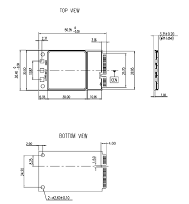
Dimension
The package of the mini PCIE module is 52 pin PCIE with a dimension of 51 mm × 30.4 mm ×
3.4 mm. It is applied to the user interface board, and can be used as a wireless terminal in a
network environment.
2
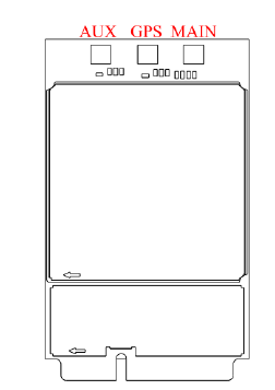
Position of RF Connectors
The PCIE module provided three antenna connectors (MAIN_ANT, GPS_ANT and AUX_ANT) for
connecting the external antennas.
3
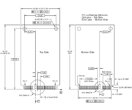
Pin Definitions
The sequence of mini-PCIE interface is shown below.
4

5
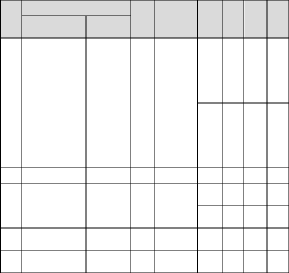
The Pin definitions of the Mini PCIE interface is shown below.
Pin
No.
Pin Name
Pad
Type
Description
Para
meter
Min
.(V)
Typ.(
V)
Max
.(V)
Mini PCI Express
Standard Description
HUAWEI Pin
Description
1 WAKE# WAKE# O Open
collector
active low
signal. This
signal is used
to wake up
the host.
- –0.
3
- 0.4
5
2 3.3Vaux VCC_3V3 P 3.3 V DC
supply input.
- 3.0 3.3 3.6
3 COEX1 Reserved - Reserved - - - -
4 GND GND - Ground - - - -
5 COEX2 Reserved - Reserved - - - -
6 1.5 V NC - Not
connected
- - - -
7 CLKREQ# CLKREQ# - Wake up in
from host
- - - -
8 UIM_PWR USIM_PWR PO Power
source for
the external
USIM card
Class
C
–0.
3
1.8 1.9
8
Class
B
–0.
3
2.85 3.3

6
Pin
No.
Pin Name
Pad
Type
Description
Para
meter
Min
.(V)
Typ.(
V)
Max
.(V)
Mini PCI Express
Standard Description
HUAWEI Pin
Description
9 GND GND - Ground - - - -
10 UIM_DATA USIM_DATA I/O External
USIM data
signal
- - 1.8/
2.85
-
11 REFCLK- NC - Not
connected
- - - -
12 UIM_CLK USIM_CLK O External
USIM clock
signal
- - 1.8/
2.85
-
13 REFCLK+ NC - Not
connected
- - - -
14 UIM_RESET USIM_RESET O External
USIM reset
signal
- - 1.8/
2.85
-
15 GND GND - Ground - - - -
16 UIM_Vpp NC - Not
connected
- - - -
17 Reserved Reserved - Reserved - - - -
18 GND GND - Ground - - - -
19 Reserved Reserved - Reserved - - - -
7
Pin
No.
Pin Name
Pad
Type
Description
Para
meter
Min
.(V)
Typ.(
V)
Max
.(V)
Mini PCI Express
Standard Description
HUAWEI Pin
Description
20 W_DISABLE# W_DISABLE# I The
W_DISABLE#
signal is an
active low
signal that
when
asserted
(driven low)
by the
system shall
disable radio
operation.
The firmware
with this
feature is in
plan.
VIL –0.
3
0 0.3
VIH 1.1
7
1.8 2.1
21 GND GND - Ground - - - -
22 PERST# RESIN_N I Reset
module
Active-low
VIL –0.
3
0 0.3
VIH 1.1
7
1.8 2.1
23 PERn0 NC - Not
connected
- - - -
24 3.3Vaux VCC_3V3 P 3.3 V DC
supply input.
- 3.0 3.3 3.6

8
Pin
No.
Pin Name
Pad
Type
Description
Para
meter
Min
.(V)
Typ.(
V)
Max
.(V)
Mini PCI Express
Standard Description
HUAWEI Pin
Description
25 PERp0 NC - Not
connected
- - - -
26 GND GND - Ground - - - -
27 GND GND - Ground - - - -
28 1.5 V NC - Not
connected
- - - -
29 GND GND - Ground - - - -
30 SMB_CLK NC - Not
connected
- - - -
31 PETn0 NC - Not
connected
- - - -
32 SMB_DATA NC - Not
connected
- - - -
33 PETp0 NC - Not
connected
- - - -
34 GND GND - Ground - - - -
35 GND GND - Ground - - - -
36 USB_D- USB_DM I/O USB signal D- - - - -

9
Pin
No.
Pin Name
Pad
Type
Description
Para
meter
Min
.(V)
Typ.(
V)
Max
.(V)
Mini PCI Express
Standard Description
HUAWEI Pin
Description
37 GND GND - Ground - - - -
38 USB_D+ USB_DP I/O USB signal
D+
- - - -
39 3.3Vaux VCC_3V3 P 3.3 V DC
supply input.
- 3.0 3.3 3.6
40 GND GND - Ground - - - -
41 3.3Vaux VCC_3V3 P 3.3 V DC
supply input.
- 3.0 3.3 3.6
42 LED_WWAN# LED_WWAN# O Active-low
LED signal
indicating
the state of
the card.
- –0.
3
- 0.4
5
43 GND GND - Ground - - - -
44 LED_WLAN# NC - Not
connected
- - - -
45 Reserved Reserved - Reserved V OL –0.
3
0 0.4
5
VOH 1.3
5
1.8 2.1

10
Pin
No.
Pin Name
Pad
Type
Description
Para
meter
Min
.(V)
Typ.(
V)
Max
.(V)
Mini PCI Express
Standard Description
HUAWEI Pin
Description
46 LED_WPAN# NC - Not
connected
- - - -
47 Reserved Reserved - Reserved V OL –0.
3
0 0.4
5
VOH 1.3
5
1.8 2.1
48 1.5 V NC - Not
connected
- - - -
49 Reserved Reserved - Reserved V IL –0.
3
0 0.6
3
VIH 1.1
7
1.8 2.1
50 GND GND - Ground - - - -
51 Reserved Reserved - Reserved V OL –0.
3
0 0.4
5
VOH 1.3
5
1.8 2.1
52 3.3Vaux VCC_3V3 P 3.3 V DC
supply input.
- 3.0 3.3 3.6