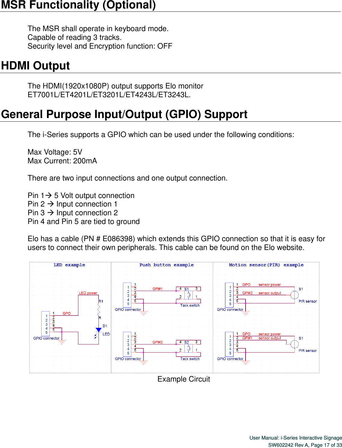
Huawei Technologies ME936 LTE Module User Manual Touchmonitor User Guide
Huawei Technologies Co.,Ltd LTE Module Touchmonitor User Guide
UserManual.wiki
>
Huawei Technologies
>
ME936 User Manual
>
User Manual
Contents
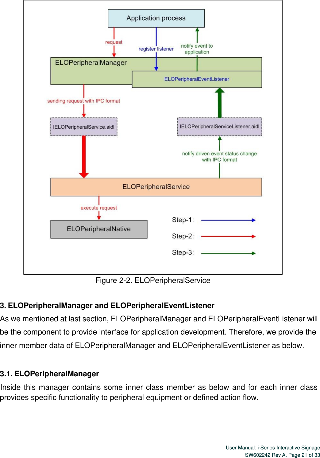
1.
UserManual.pdf
2.
UserManual_safety information.pdf
3.
User manual
4.
User Manual
User Manual
Navigation menu
Upload a User Manual
Namespaces
Wiki Guide
HTML
PDF
Info
Views
User Manual
Discussion / Help
Navigation