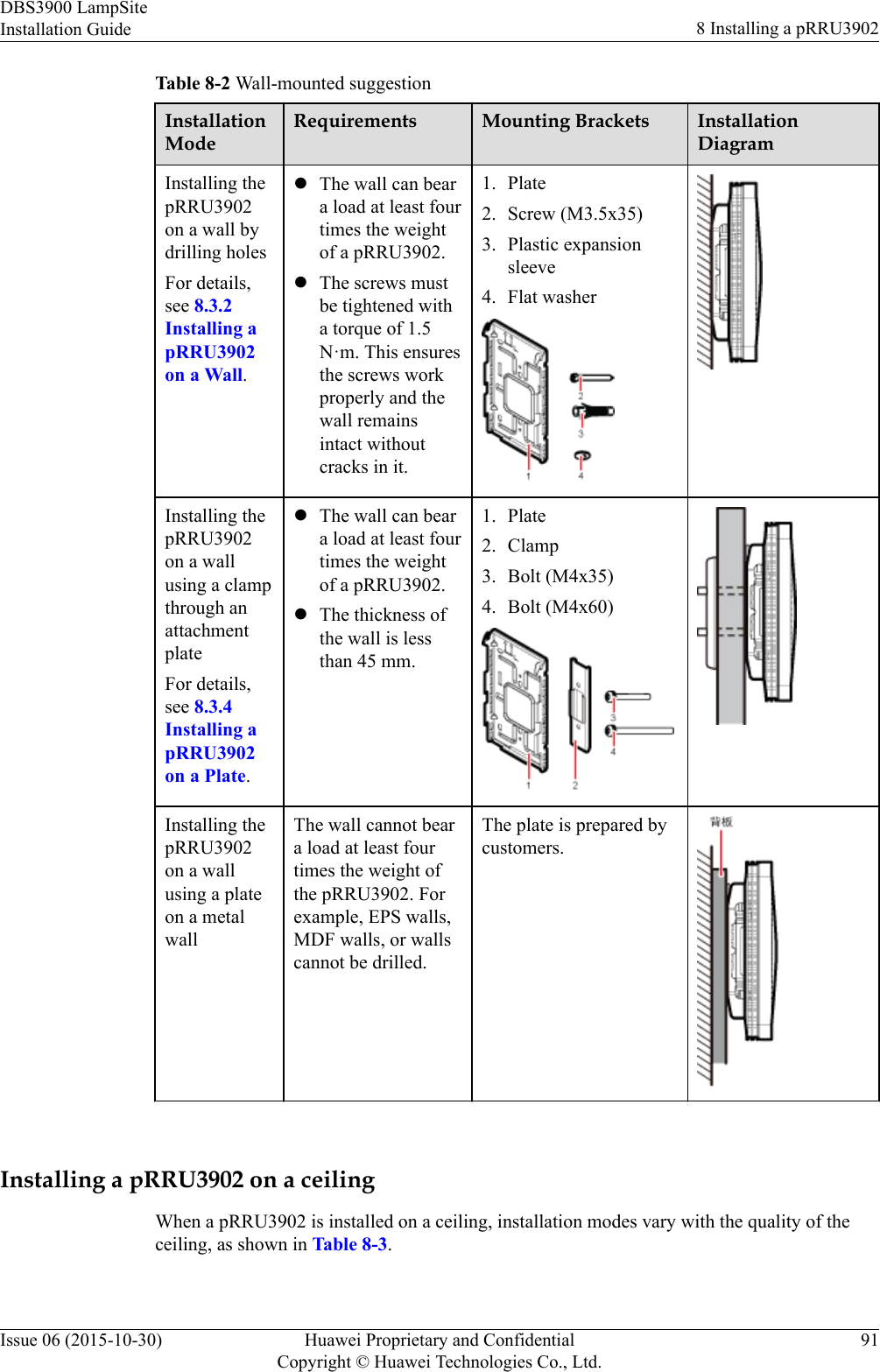
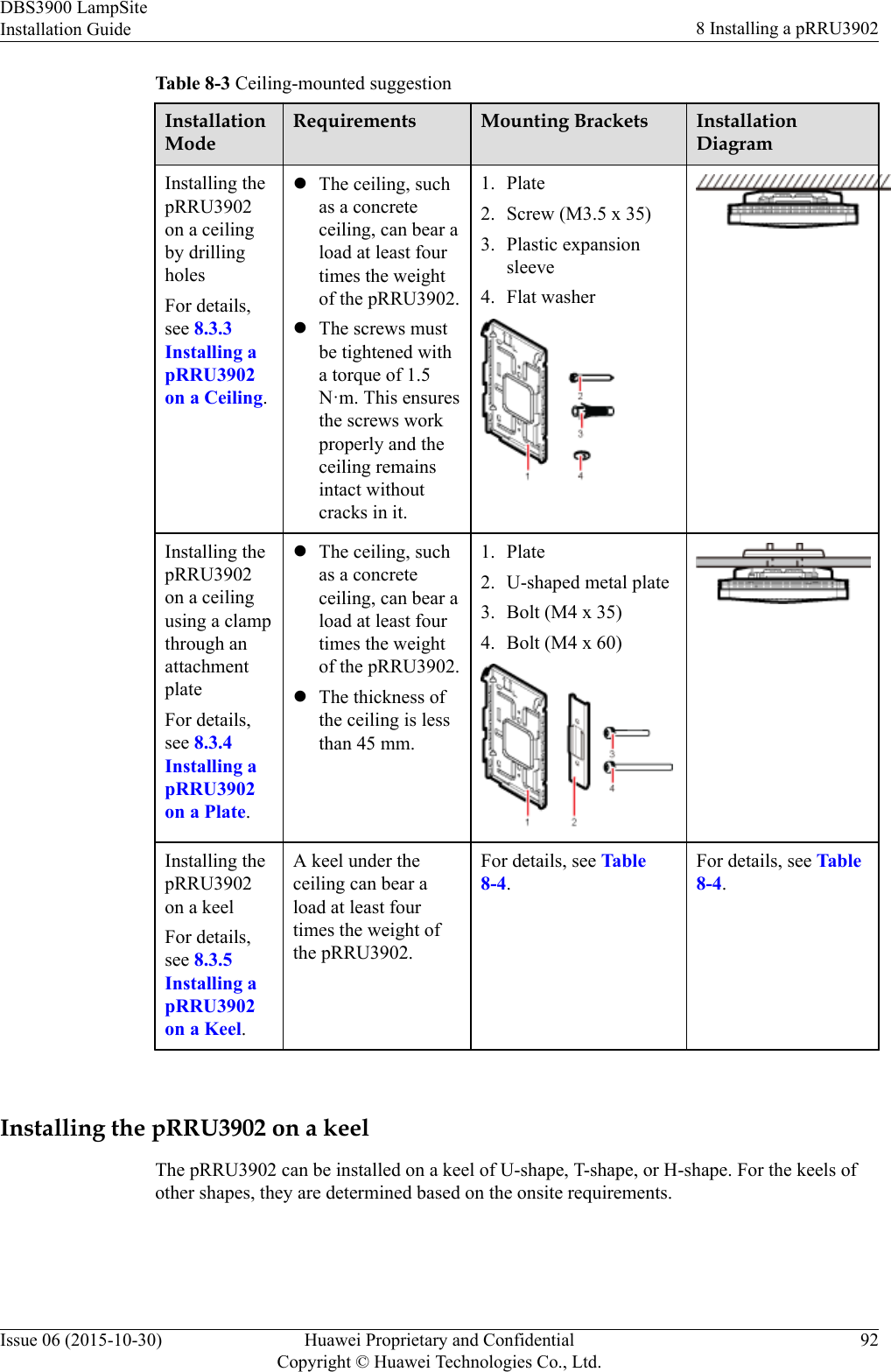
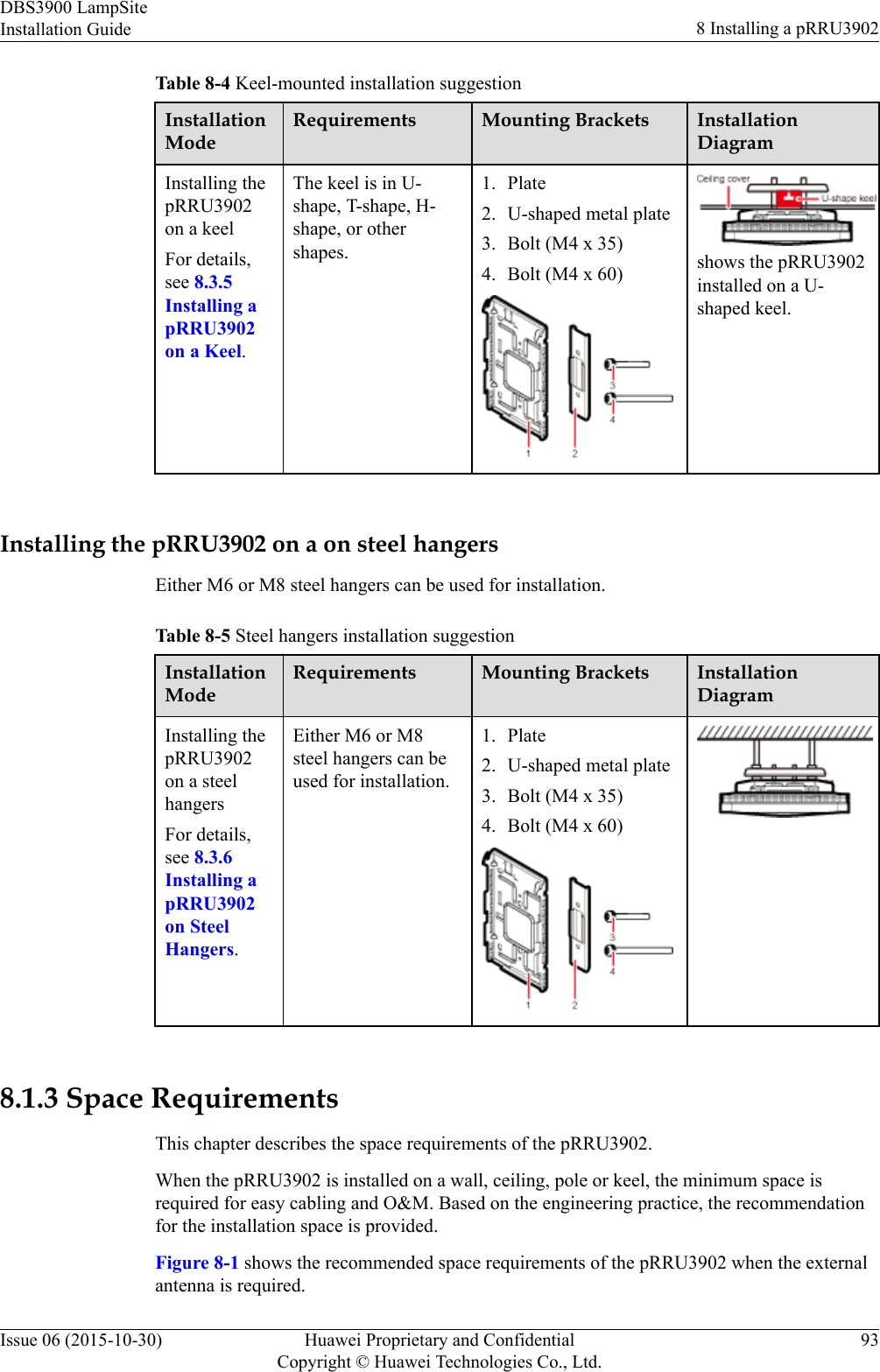
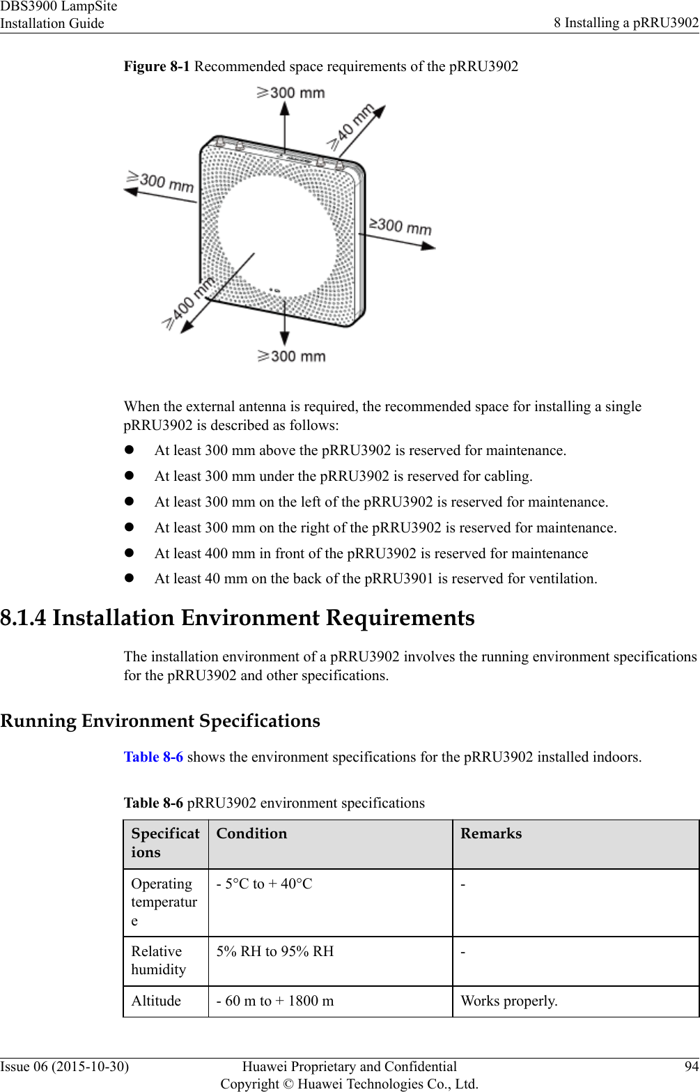
Huawei Technologies PRRU3901B2B5 pico Remote Radio Unit User Manual Installation Guide
Huawei Technologies Co.,Ltd pico Remote Radio Unit Installation Guide
UserManual.wiki
>
Huawei Technologies
>
PRRU3901B2B5 User Manual
User Manual
Navigation menu
Upload a User Manual
Namespaces
Wiki Guide
HTML
PDF
Info
Views
User Manual
Discussion / Help
Navigation
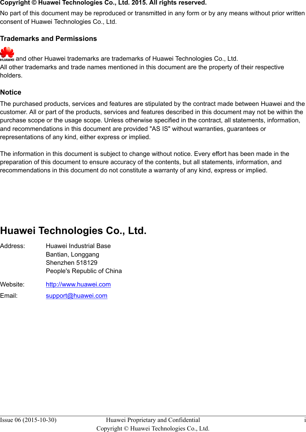
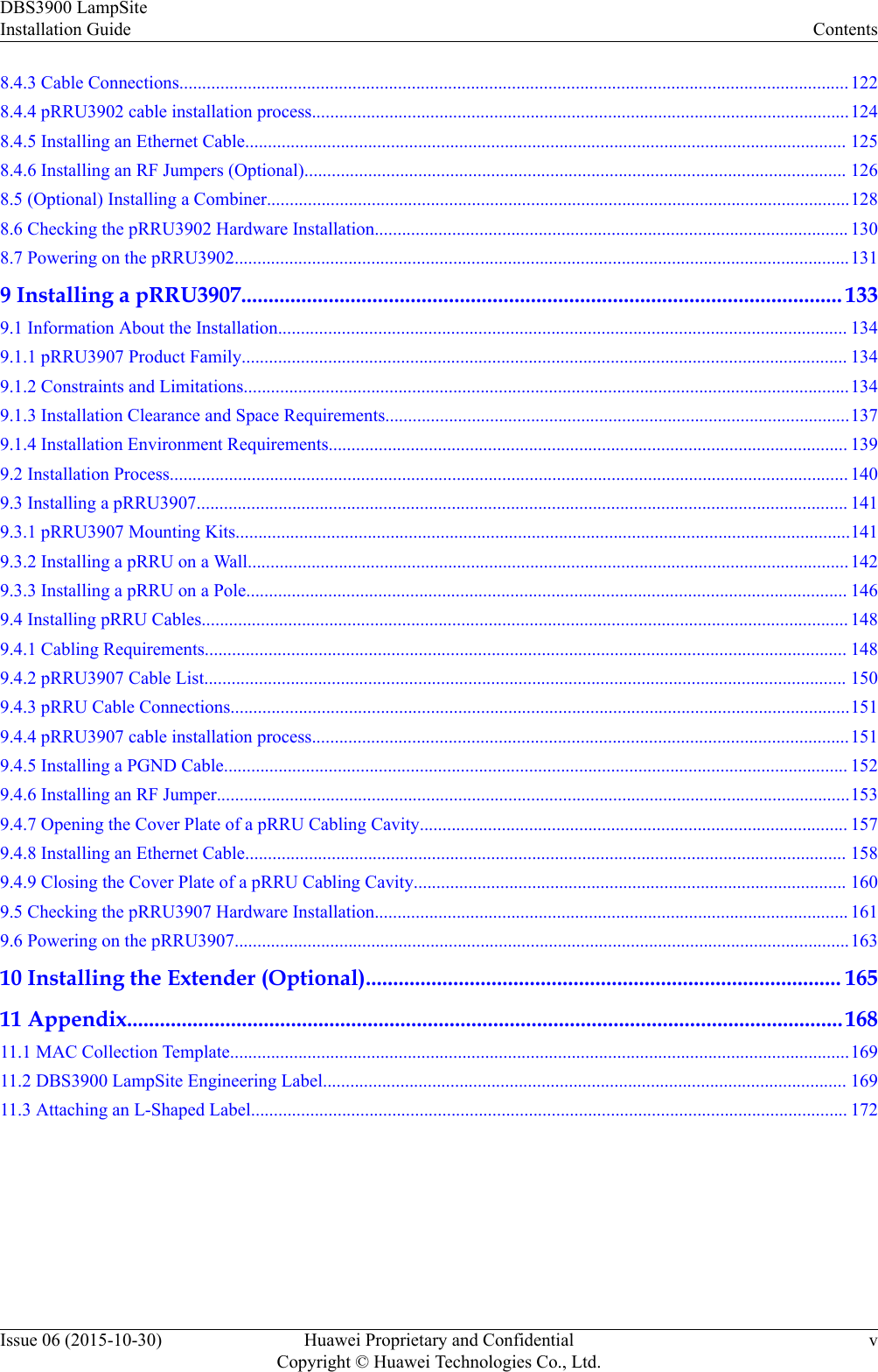
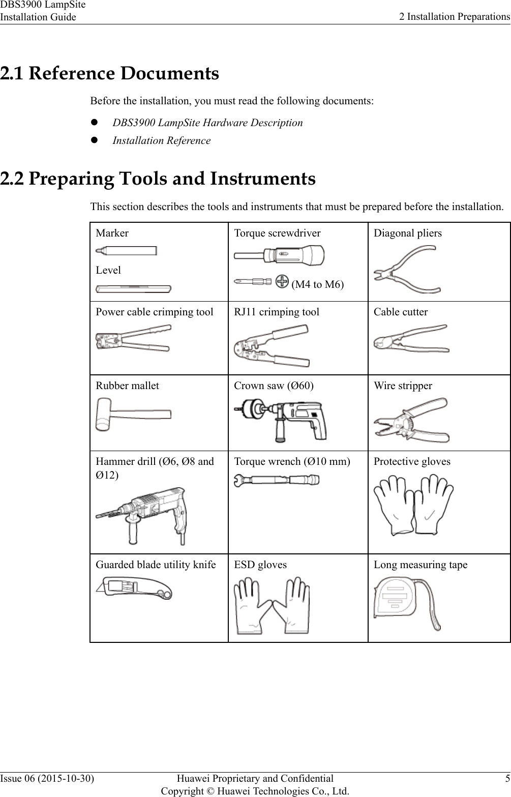
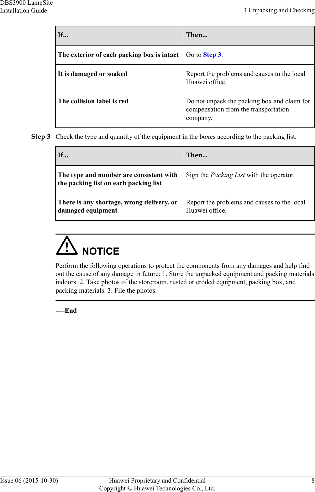

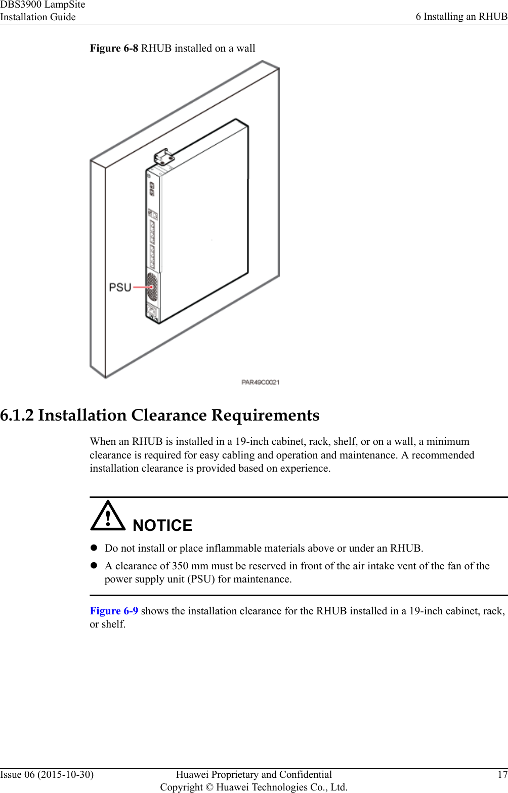
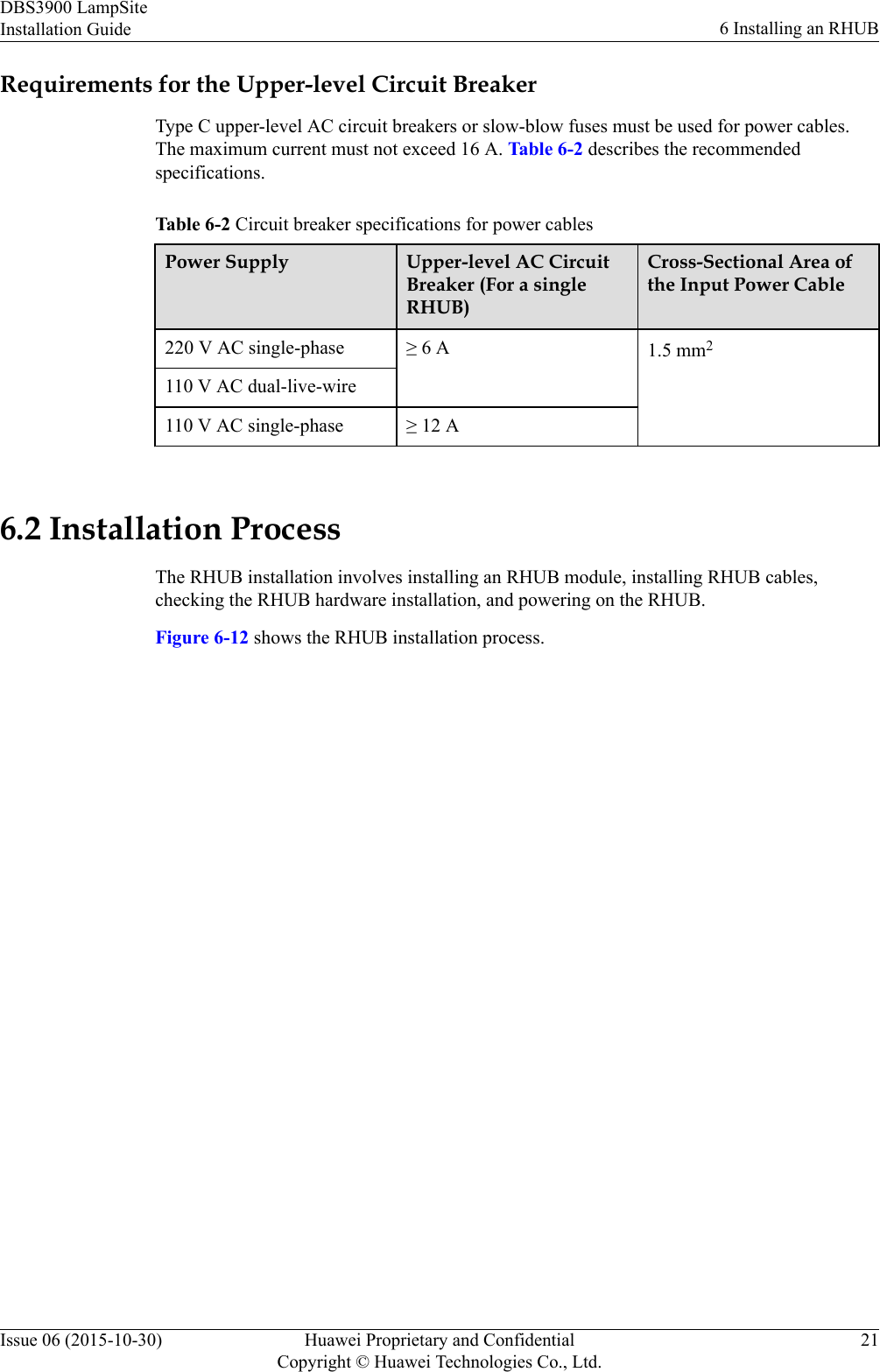
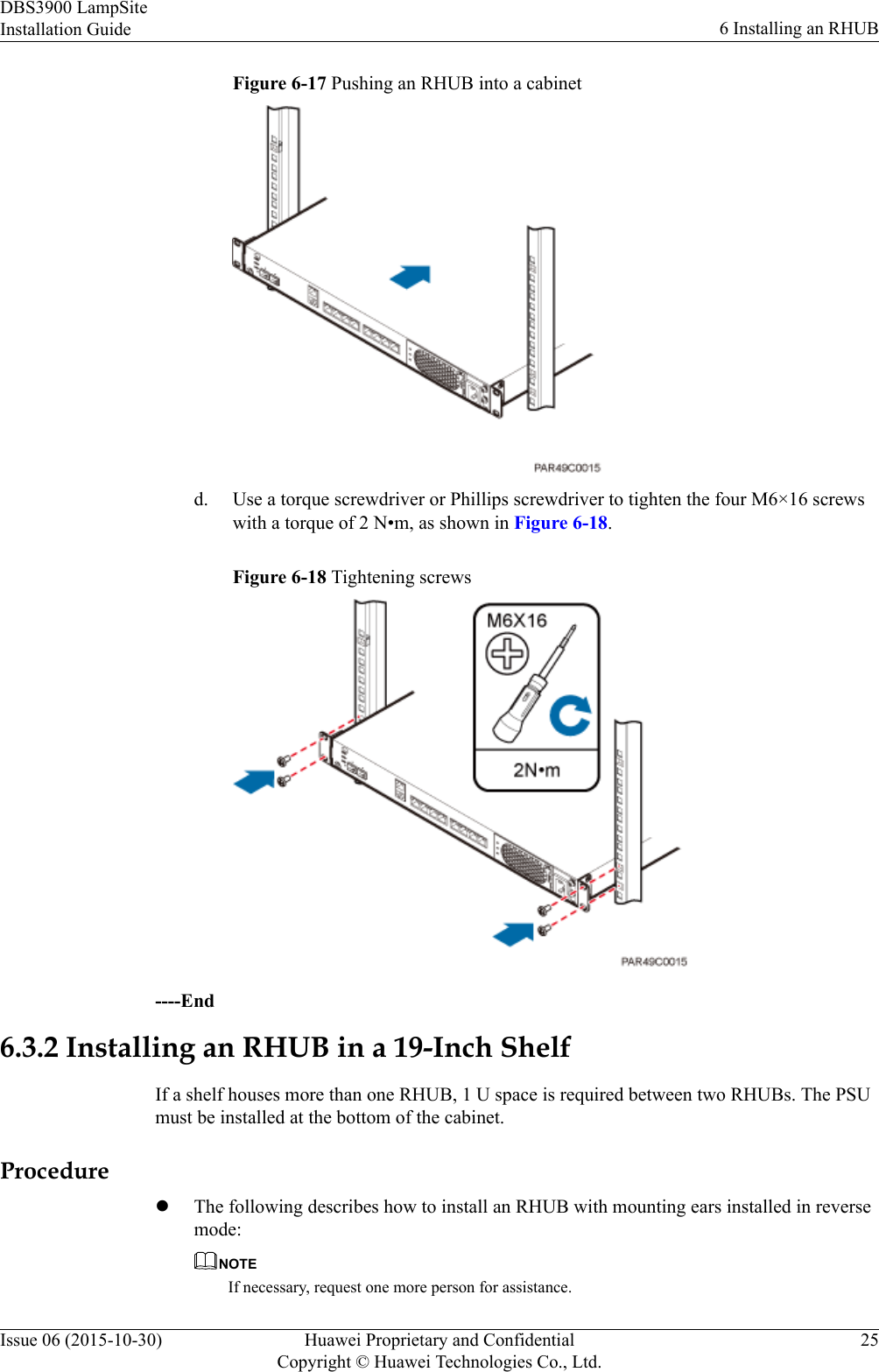
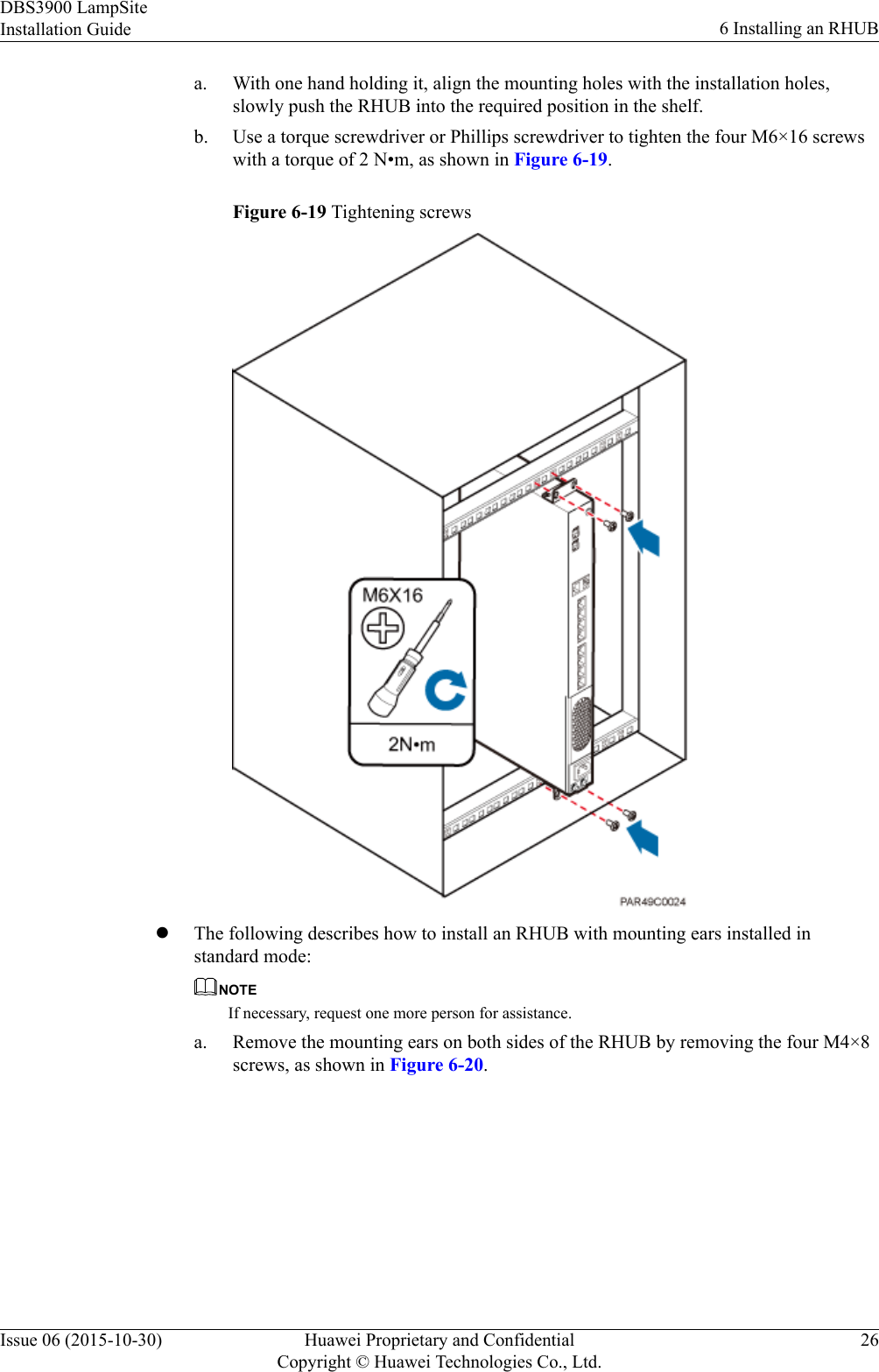
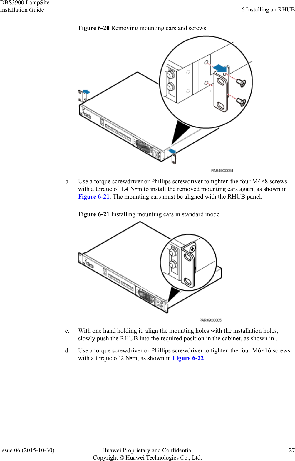
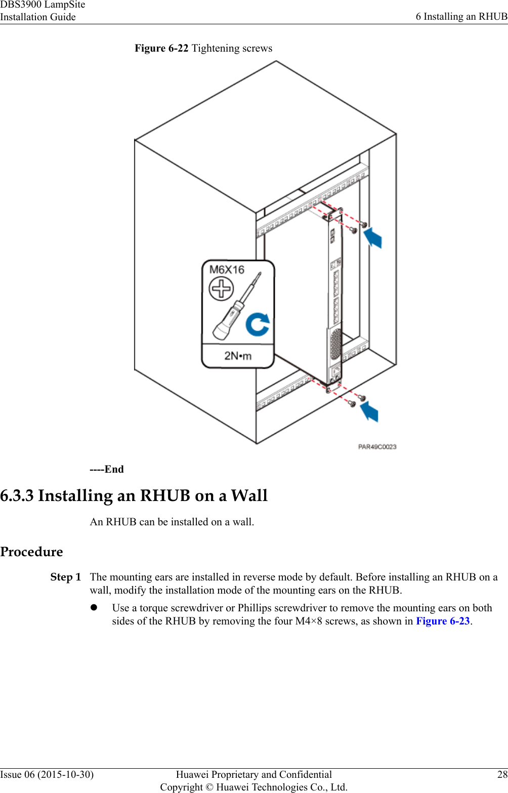
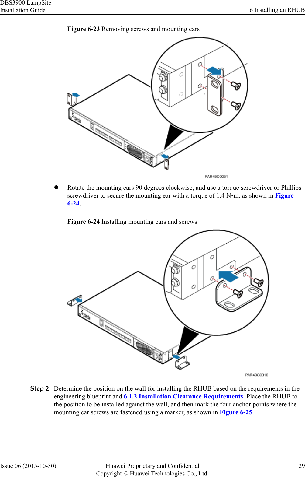
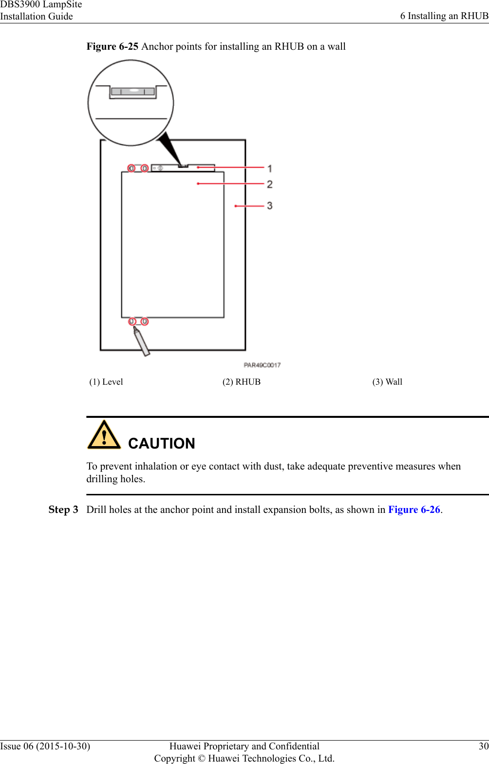
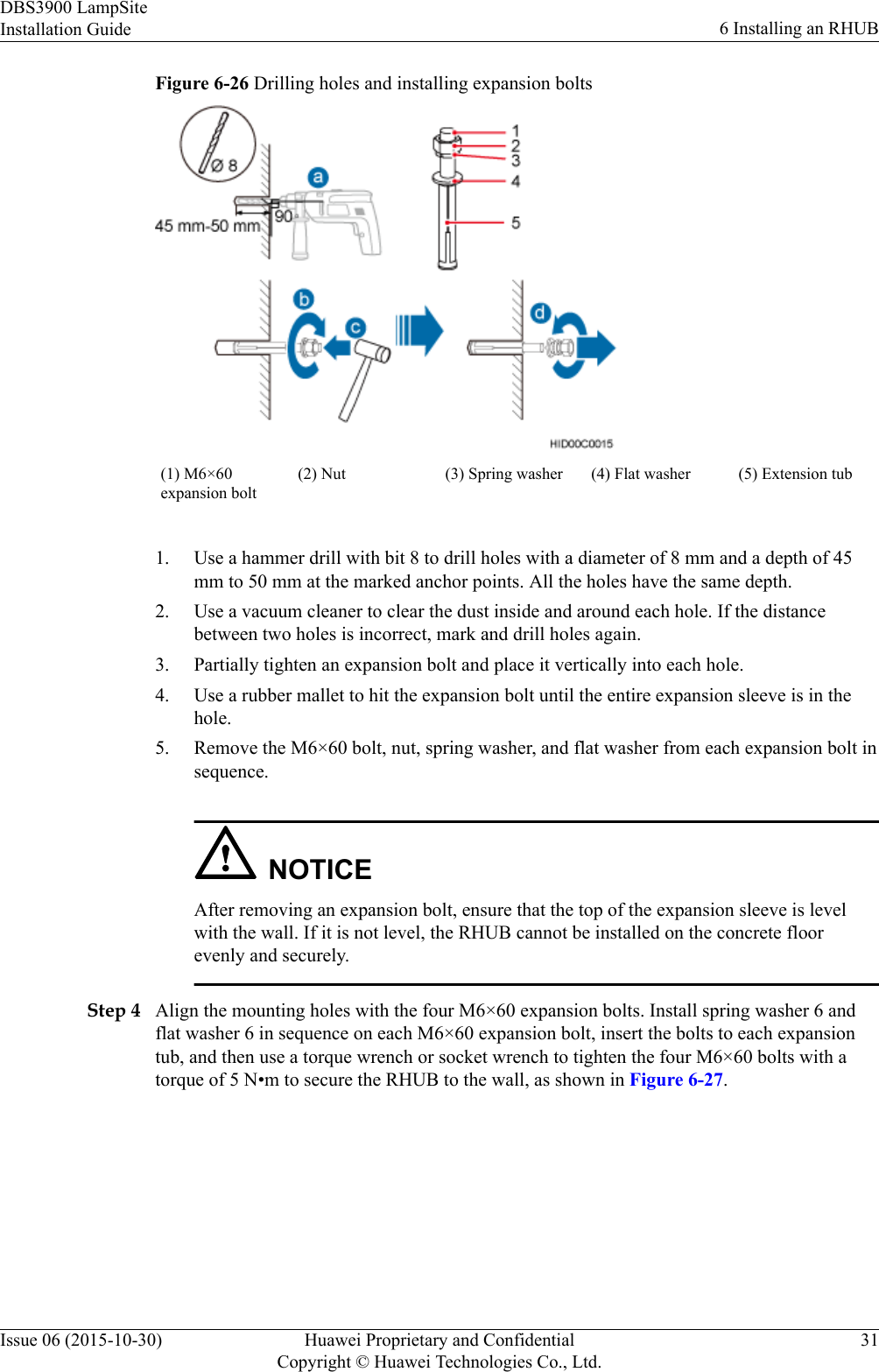
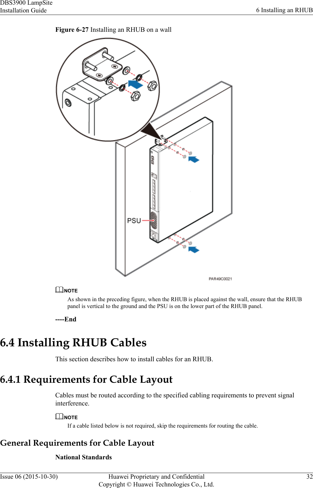
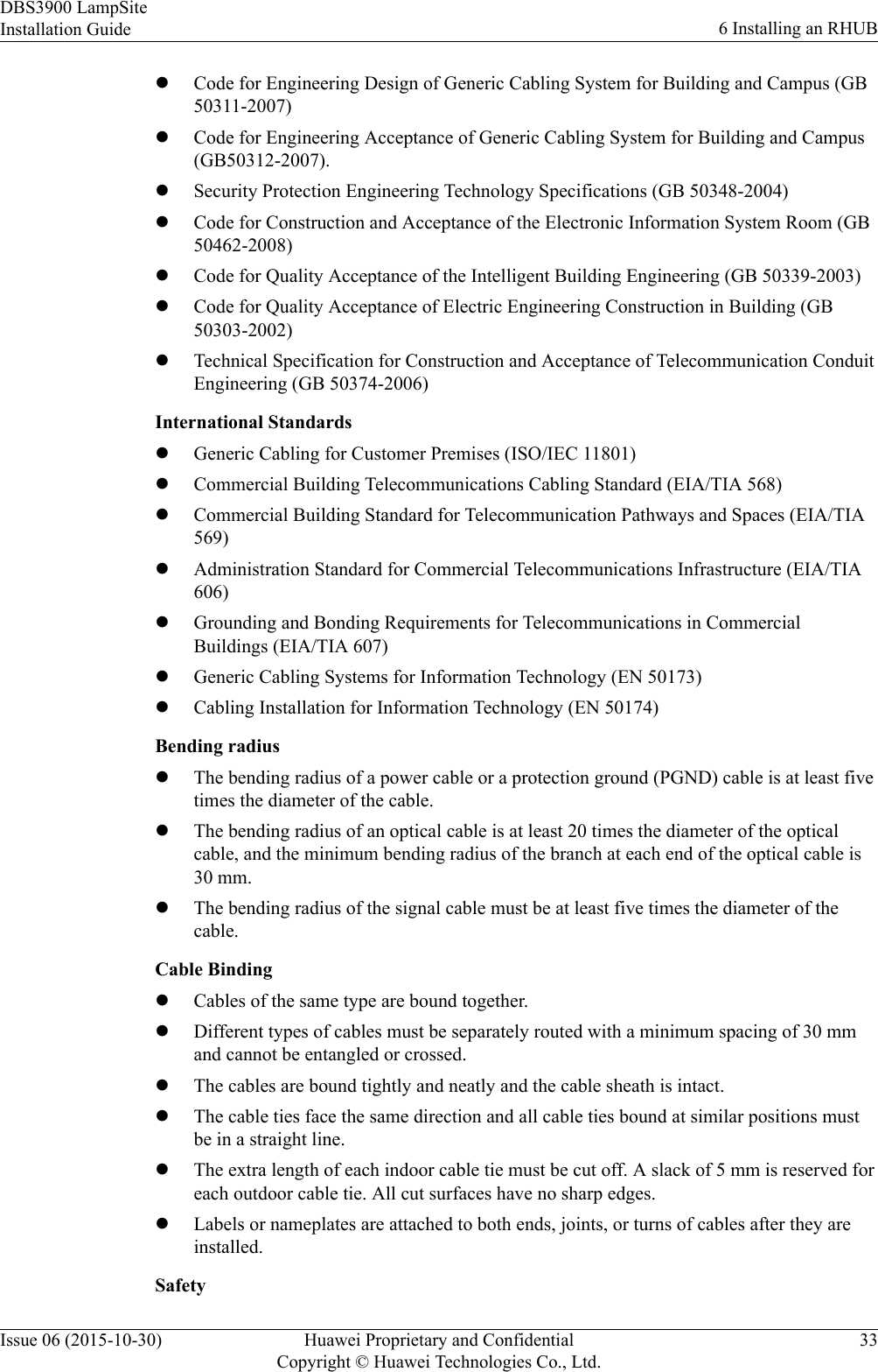
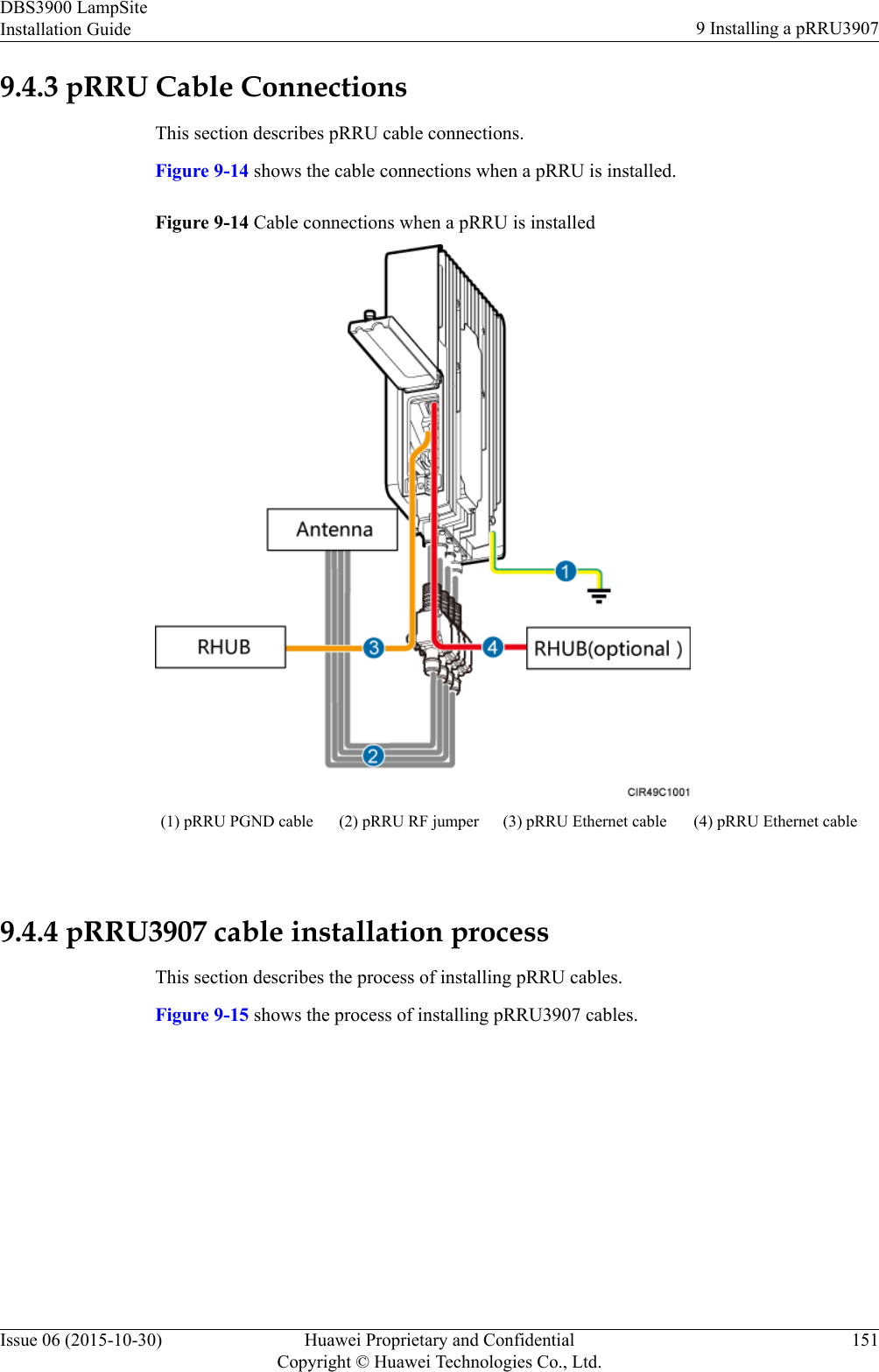
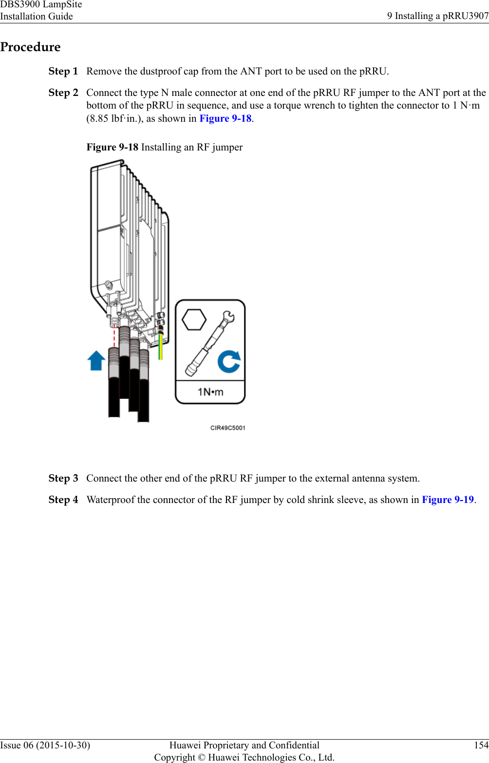
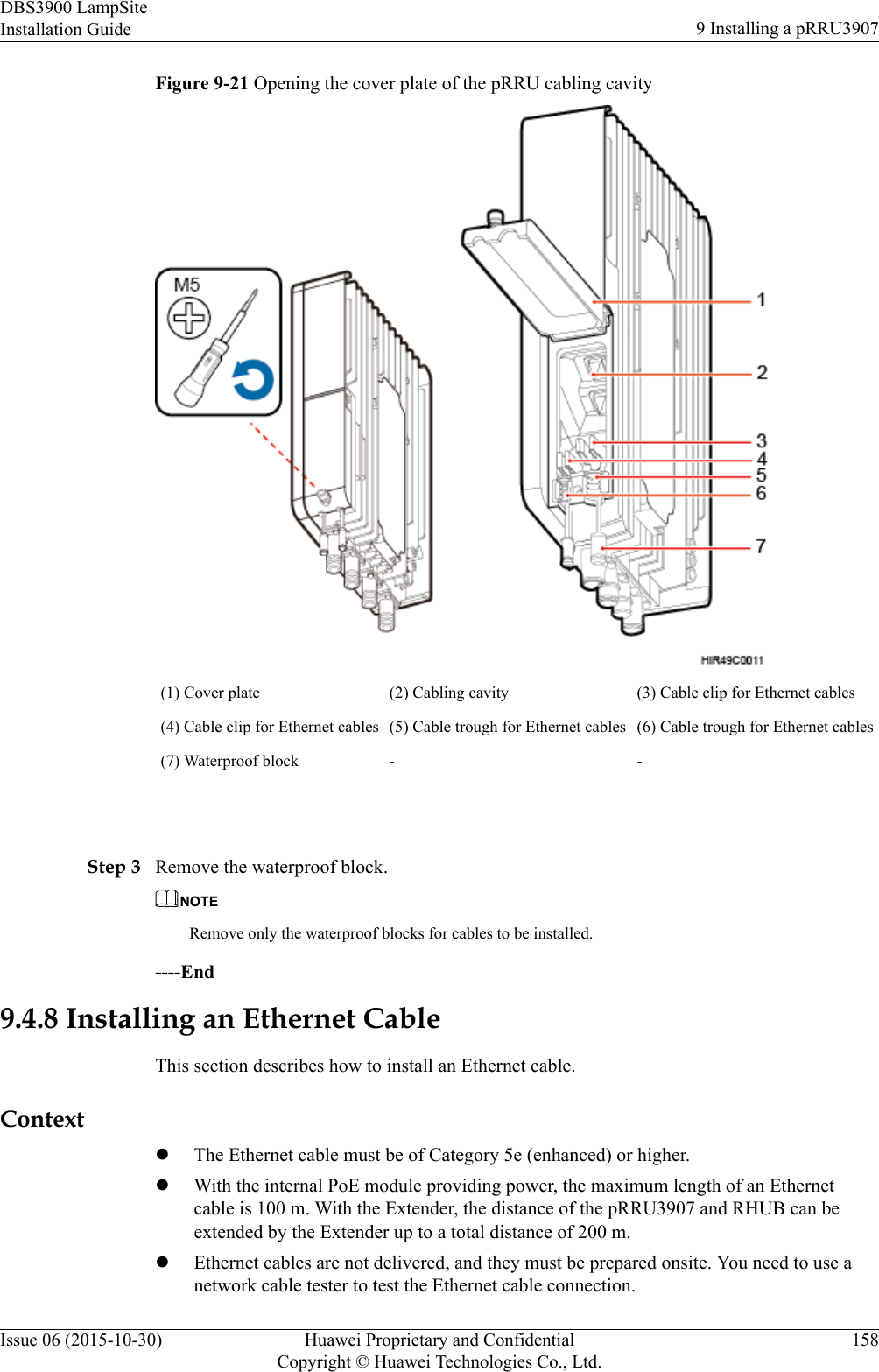
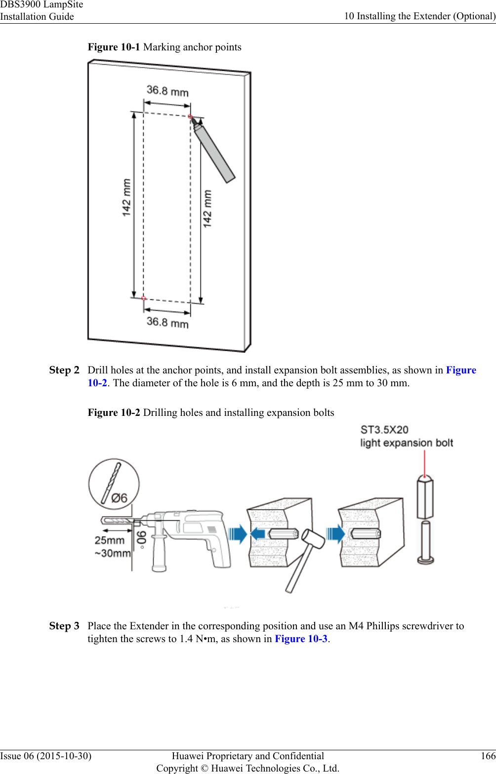
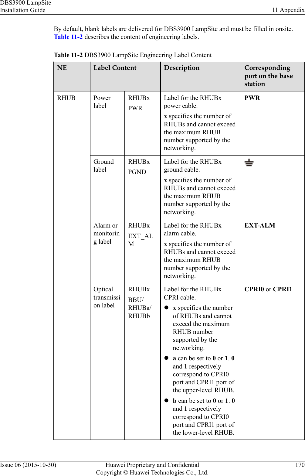
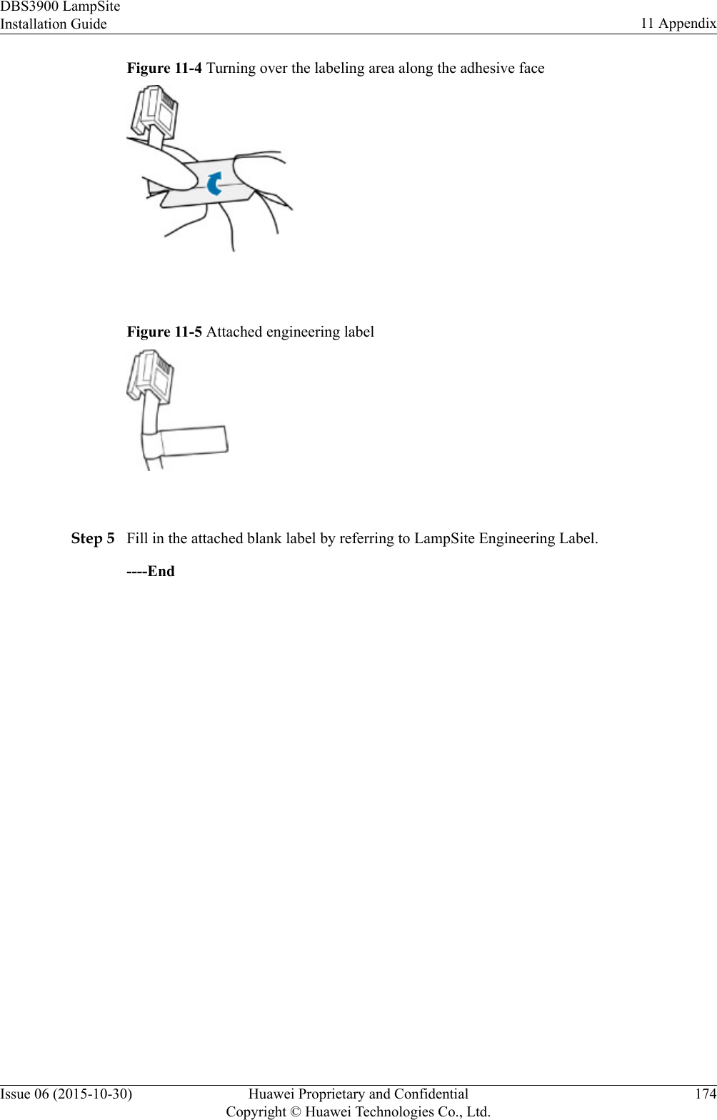
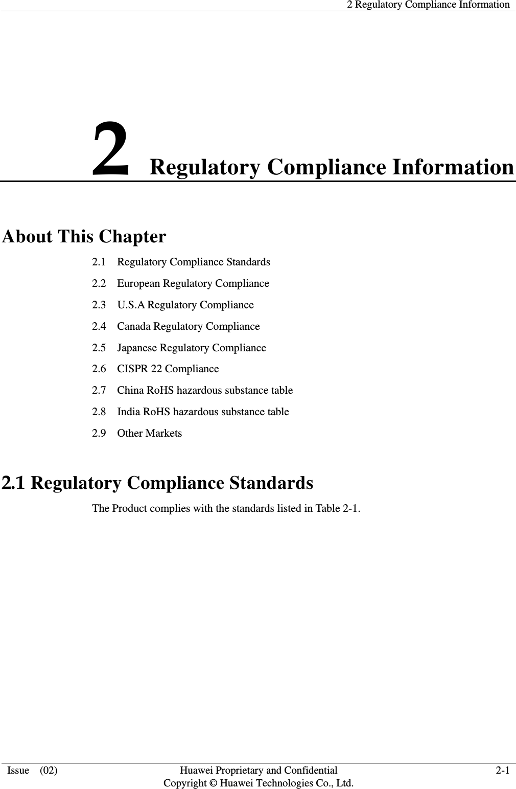
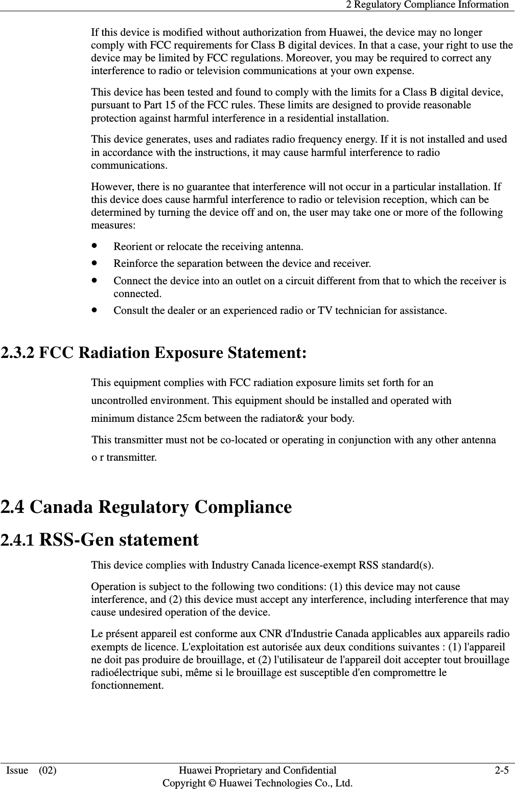
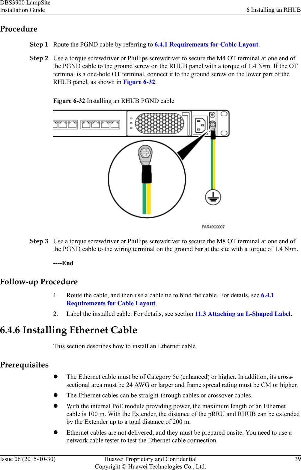
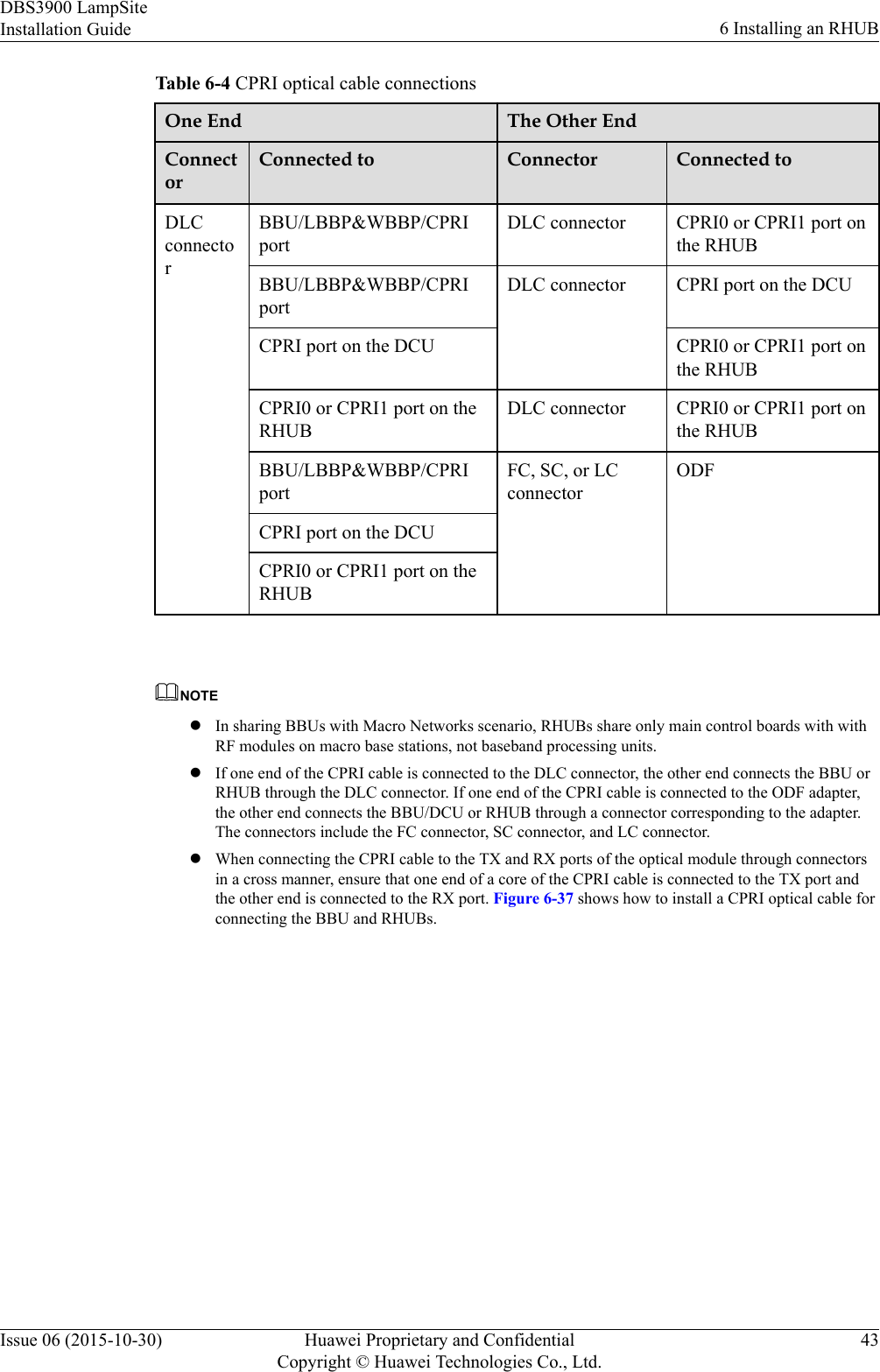
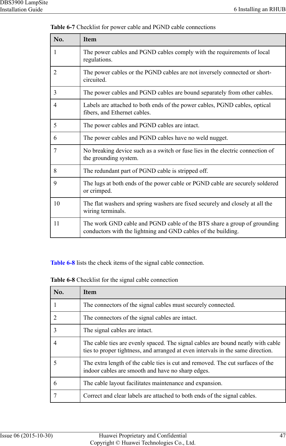
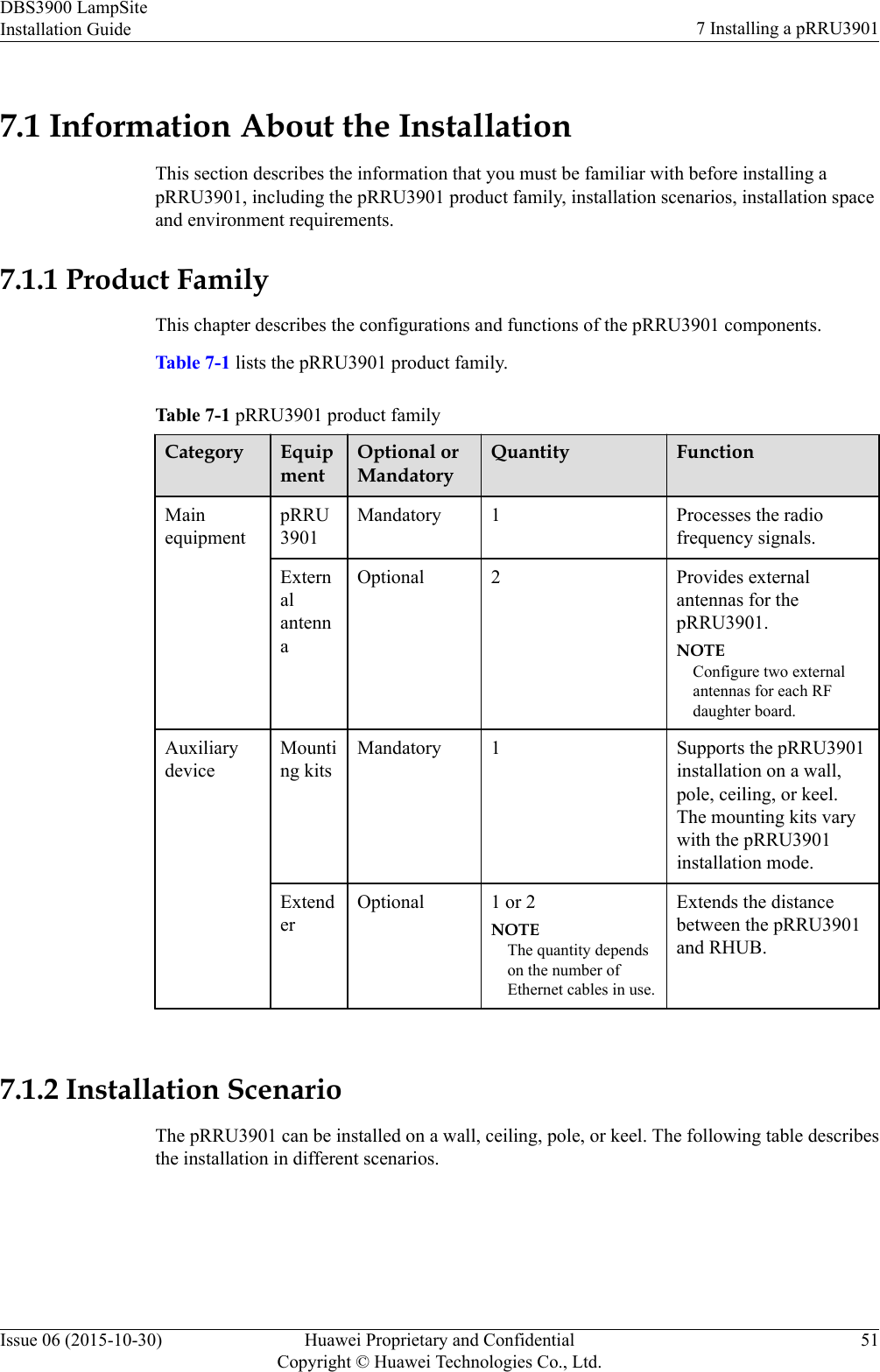
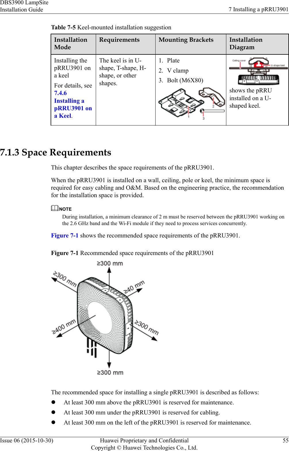
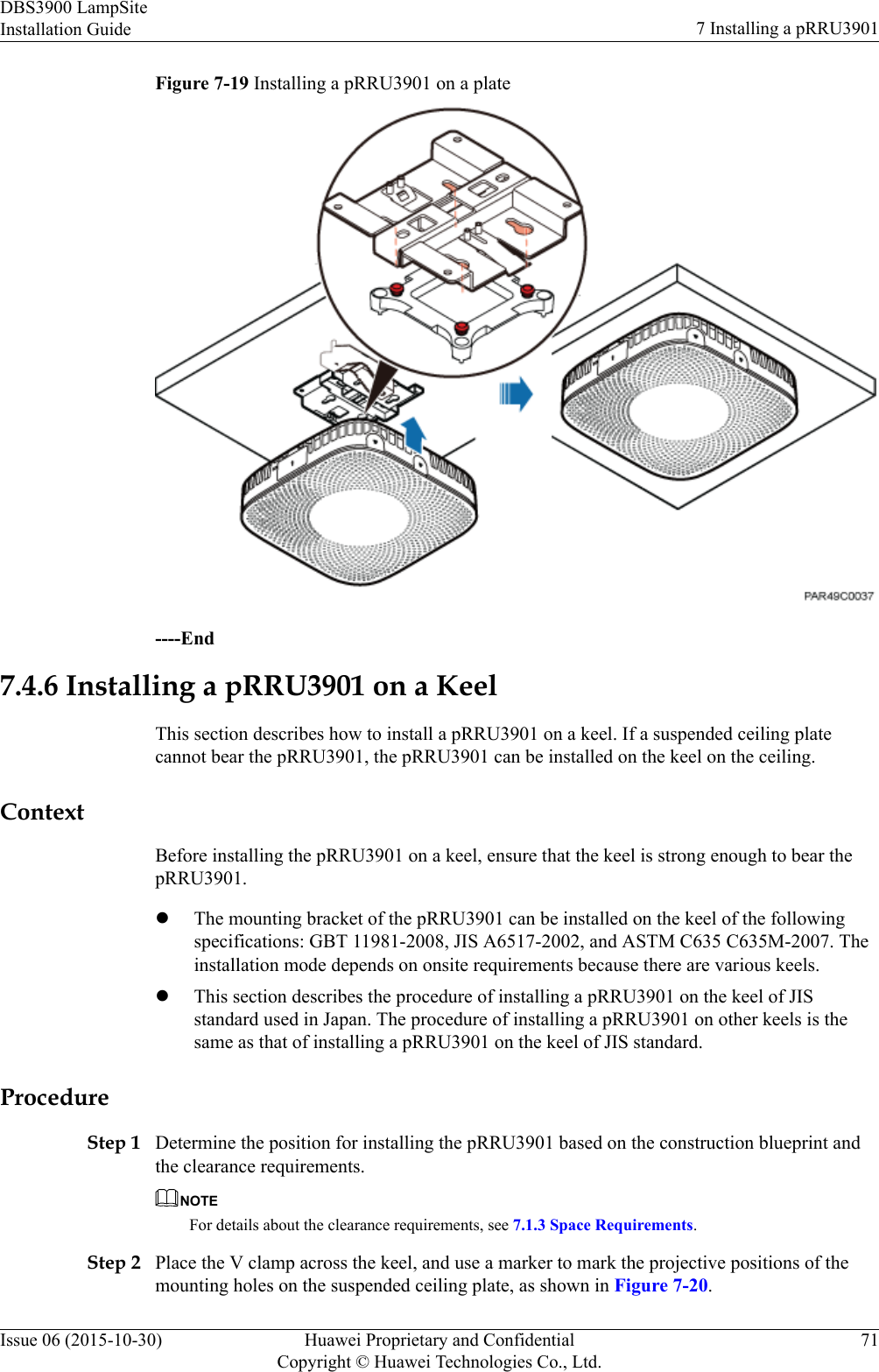
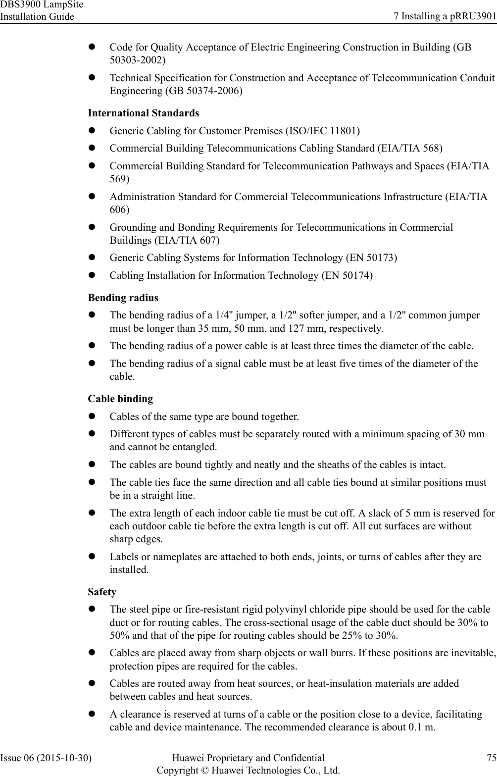
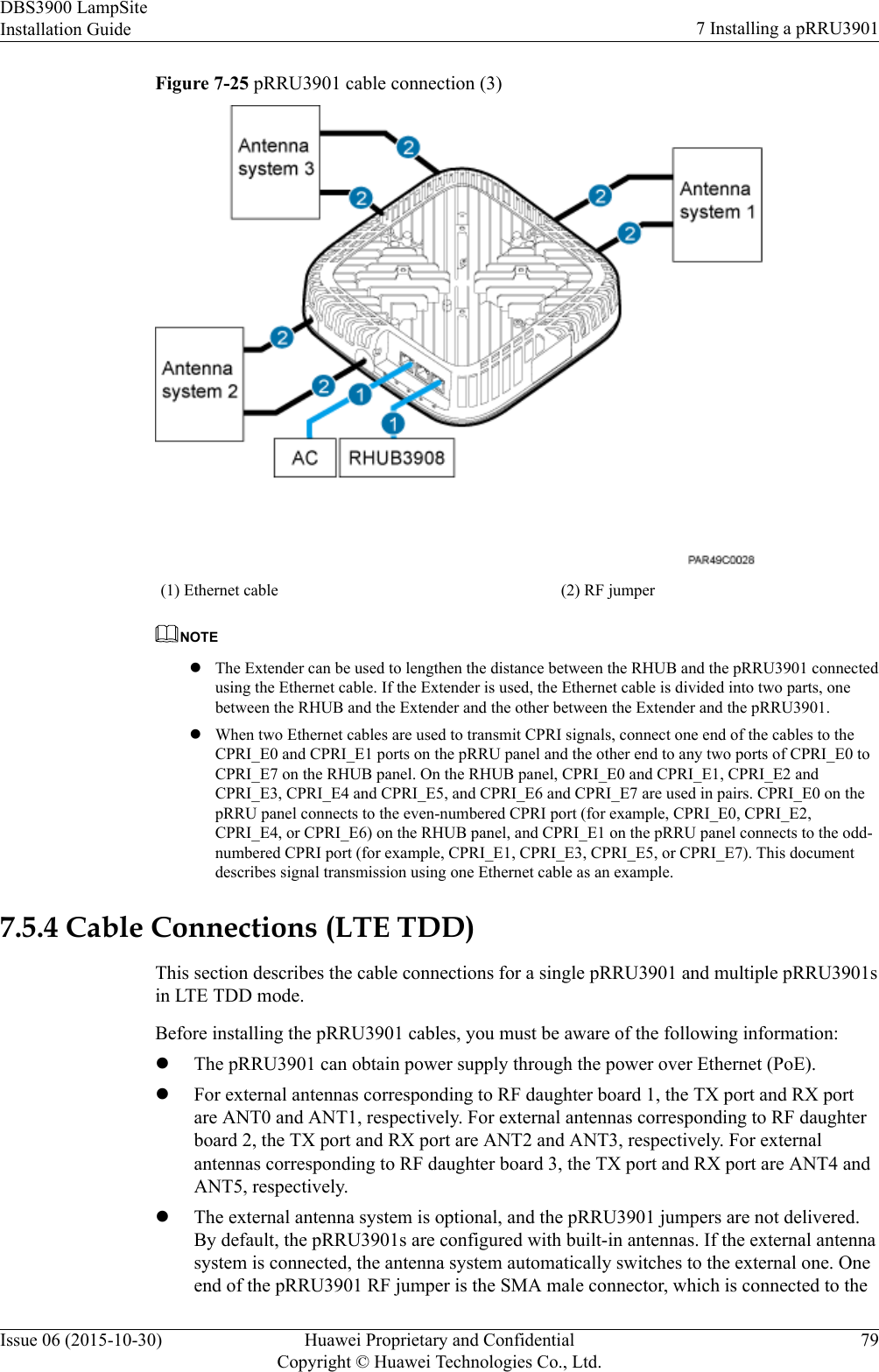
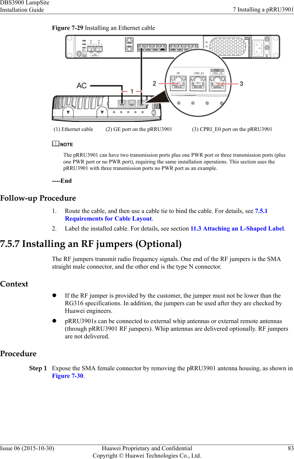
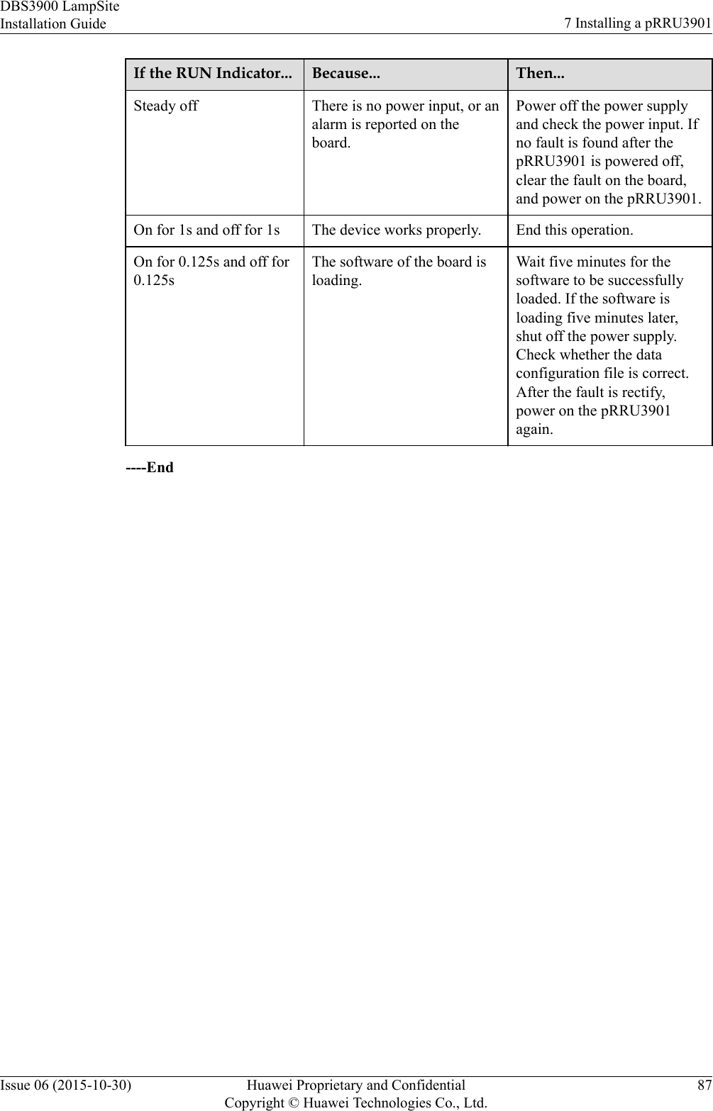
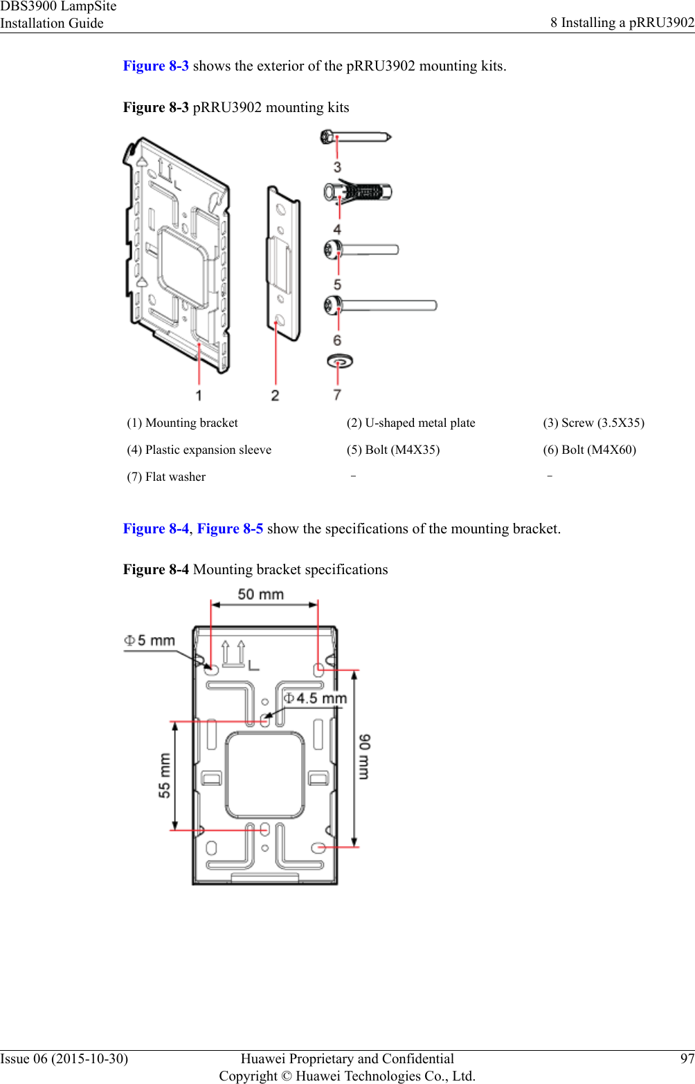
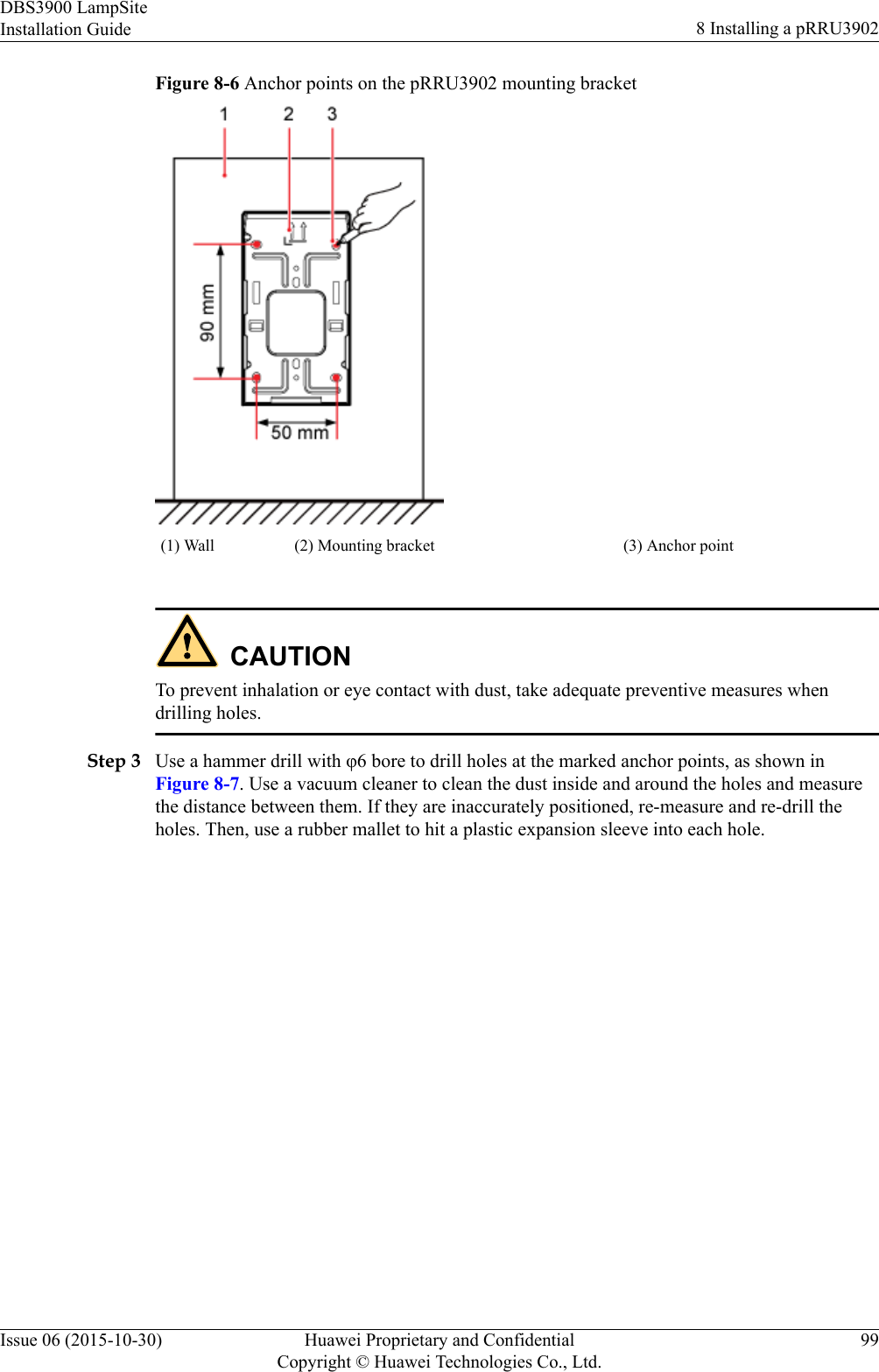
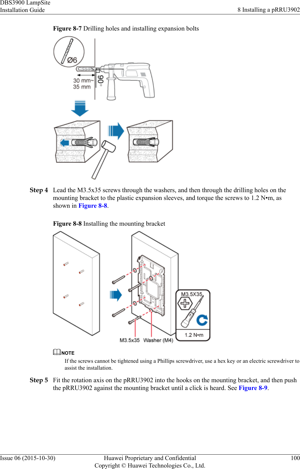
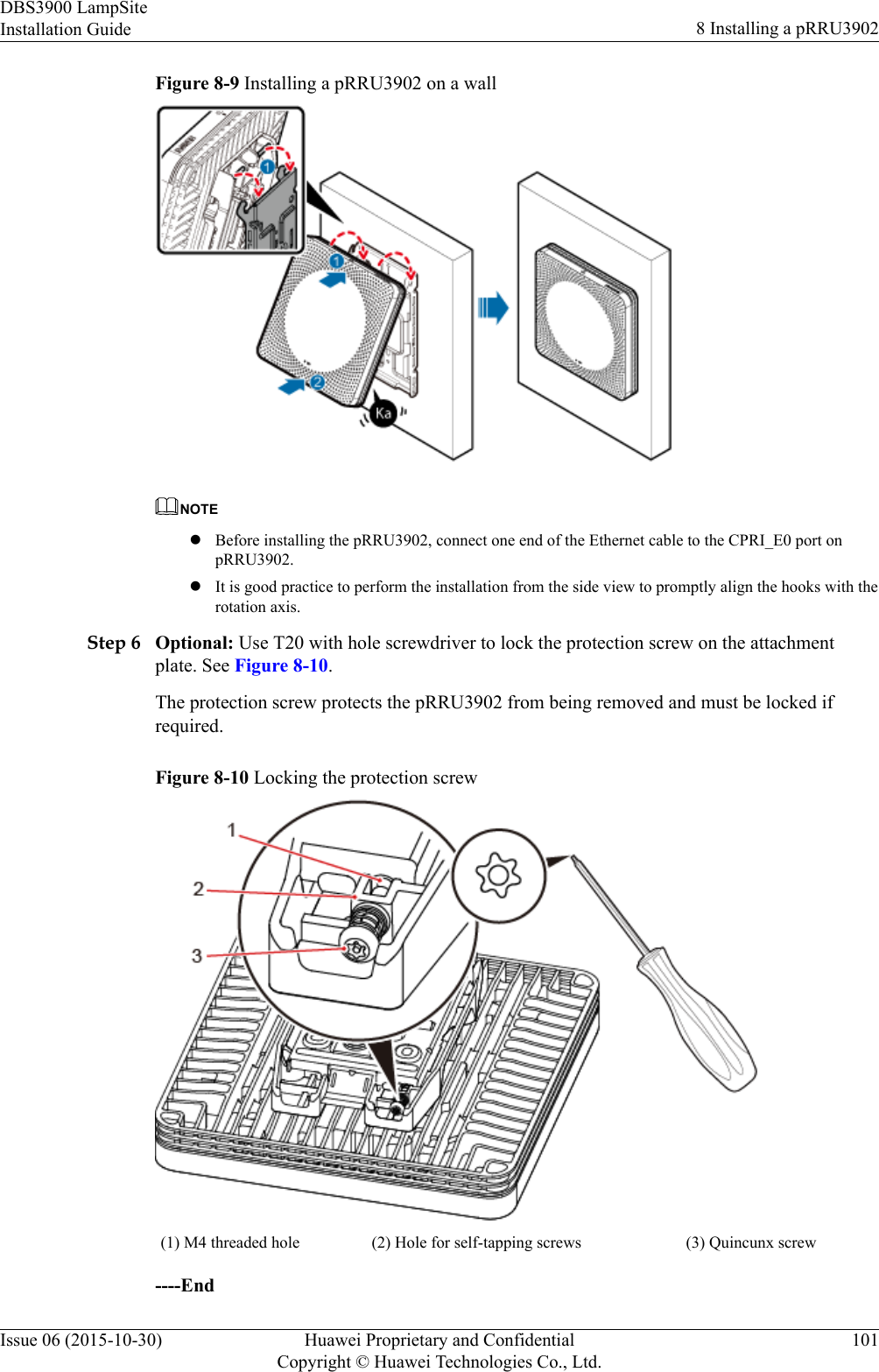
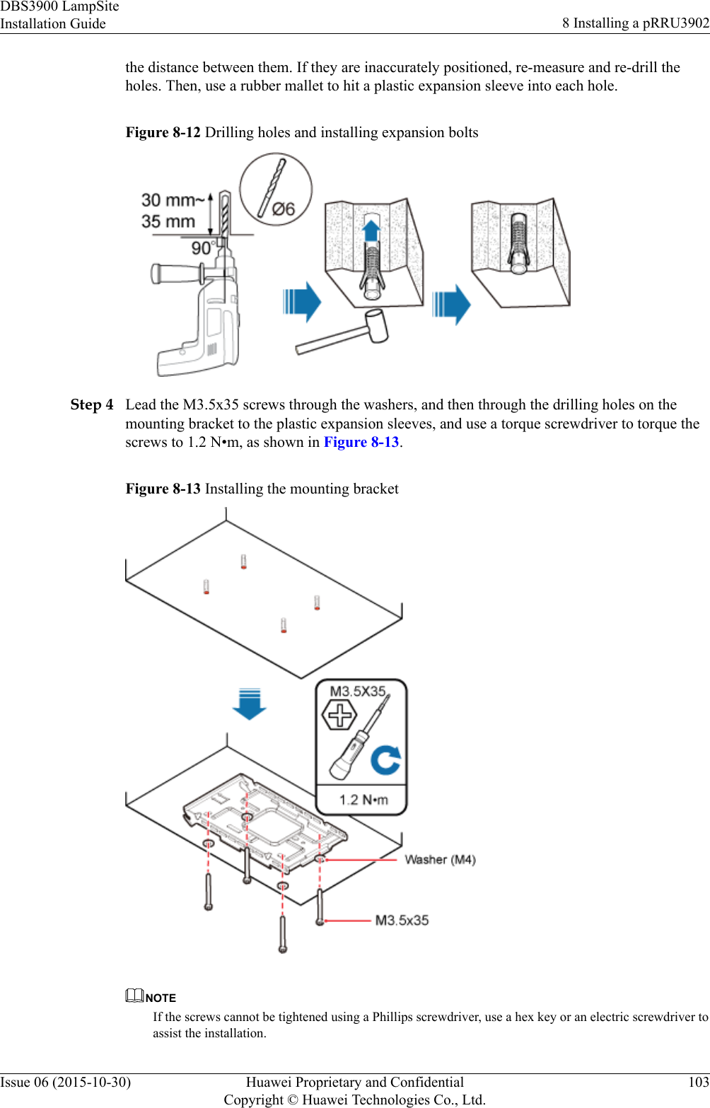
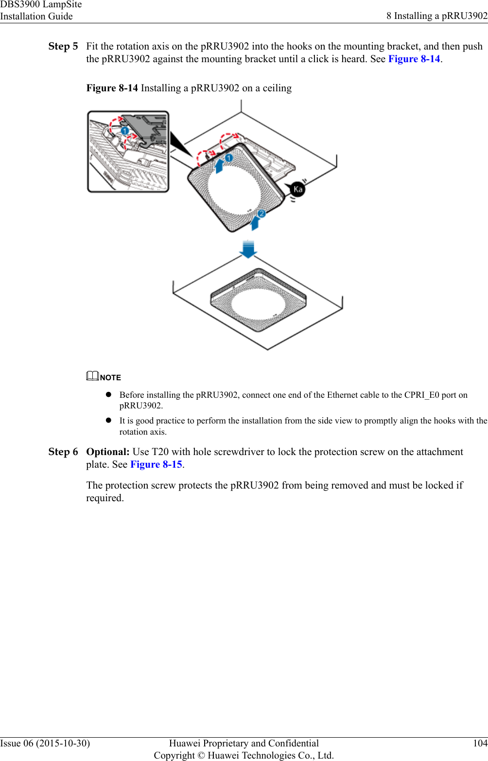
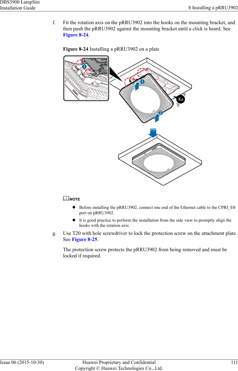
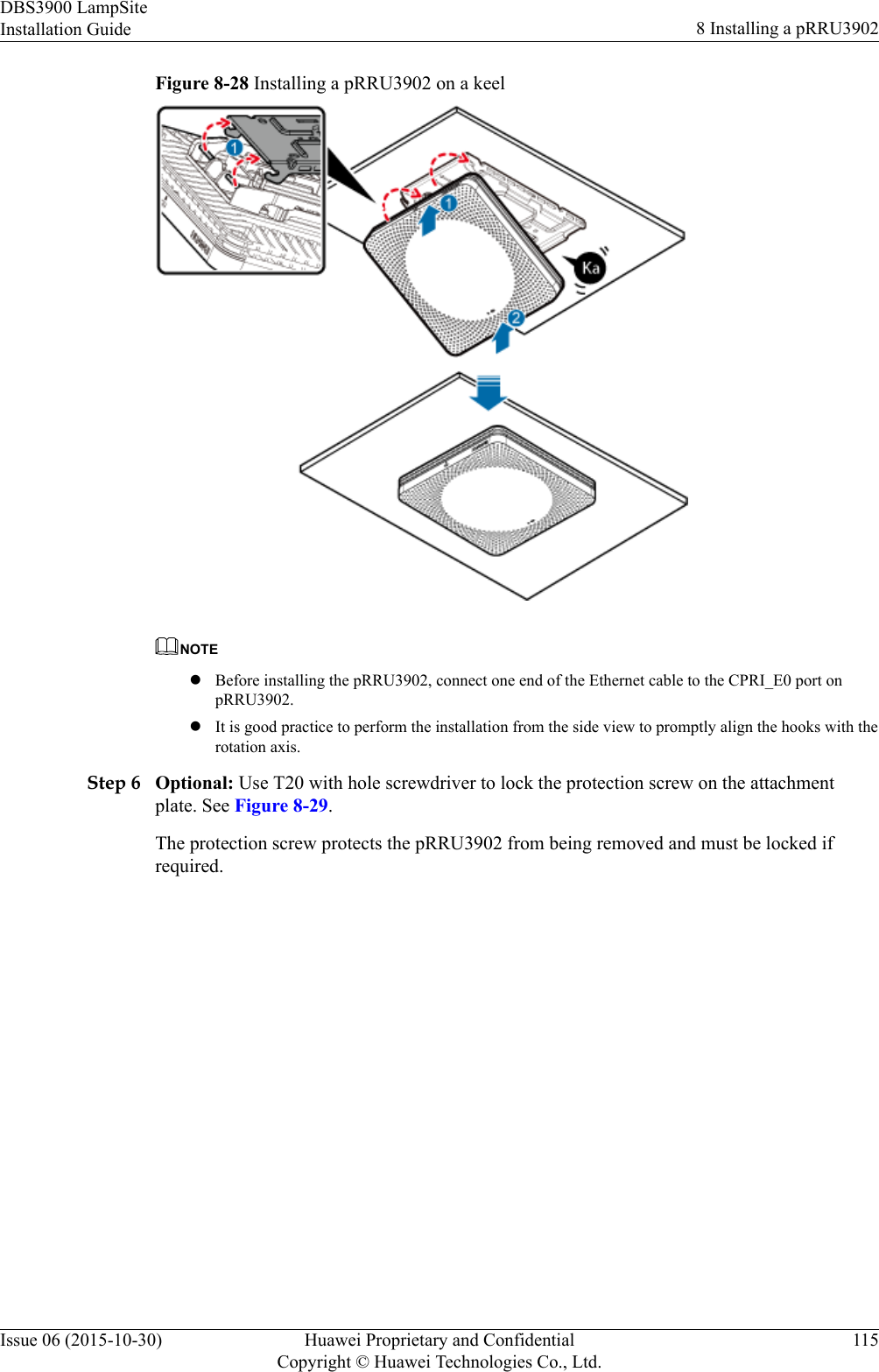
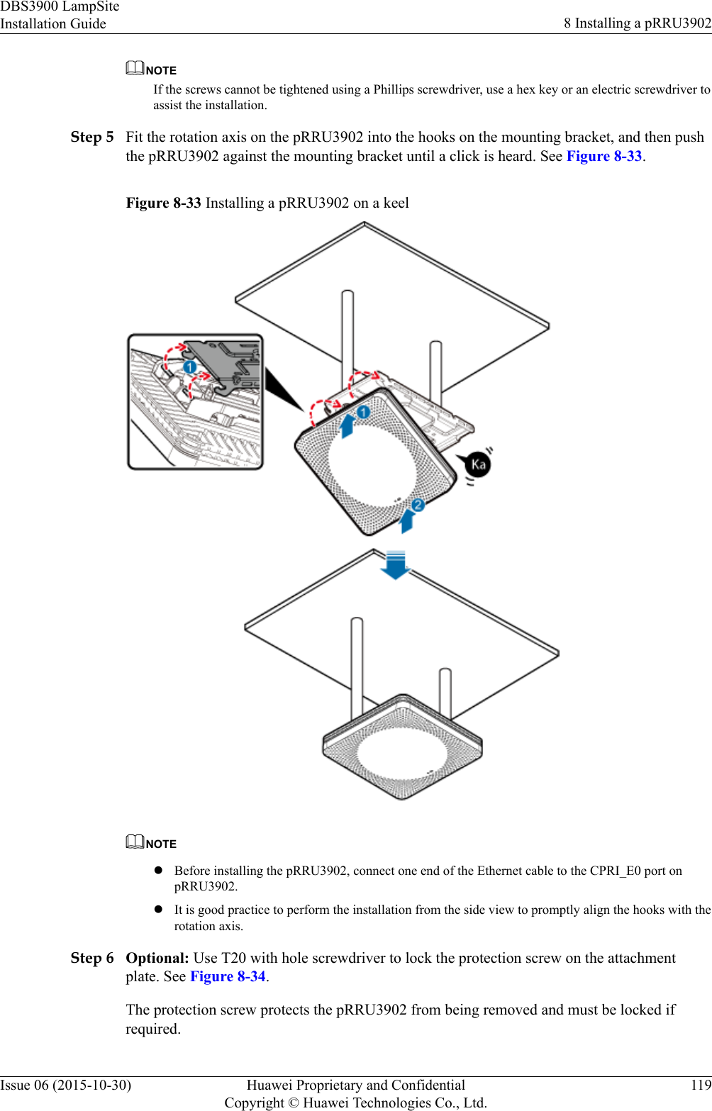
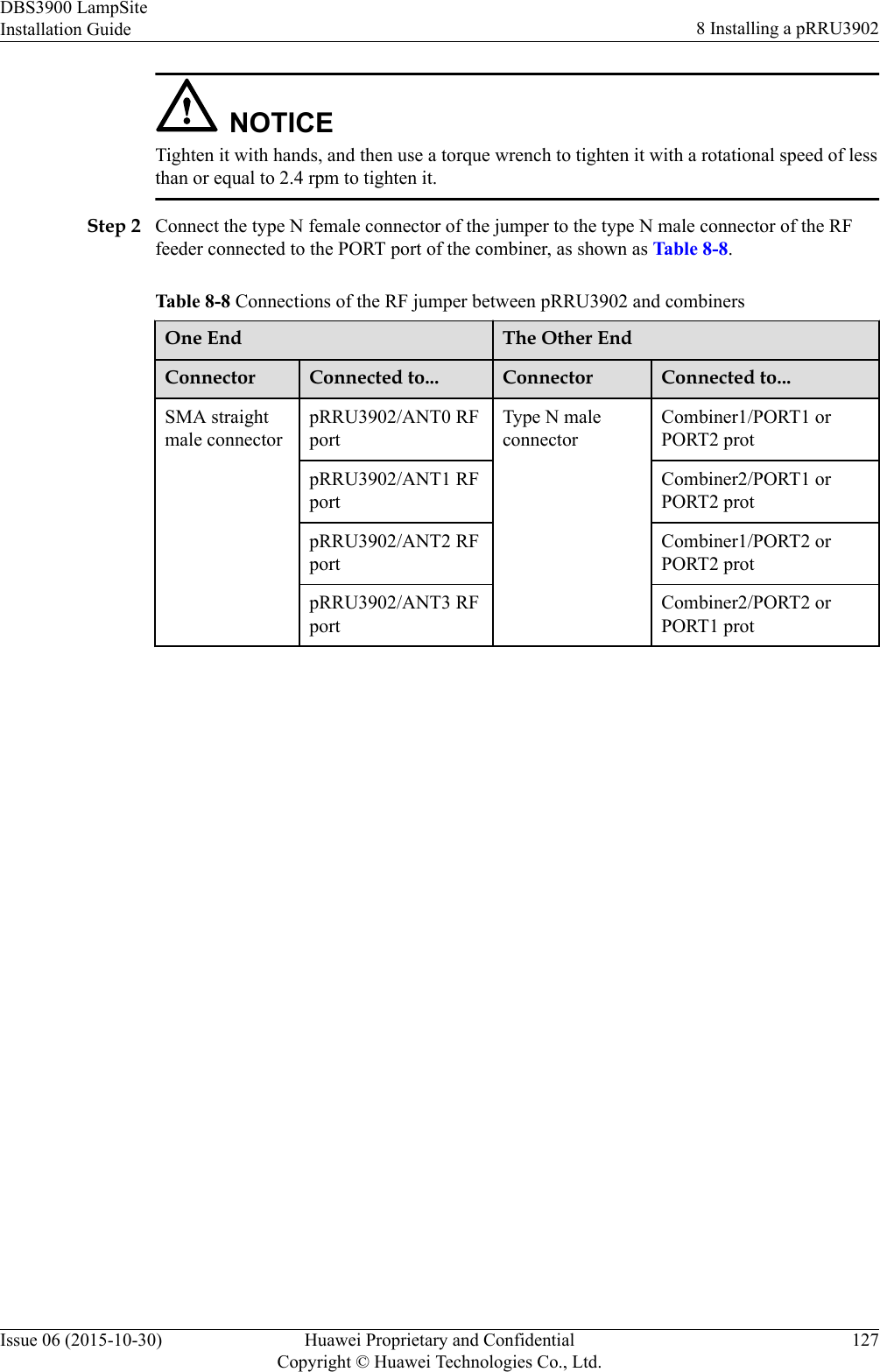
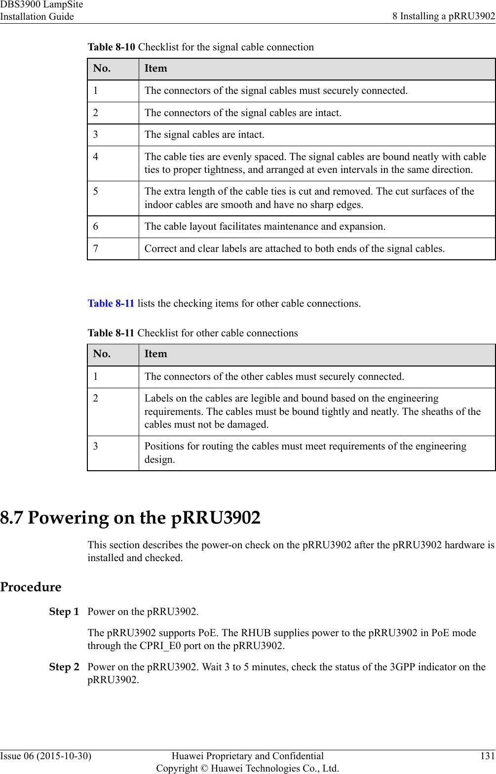
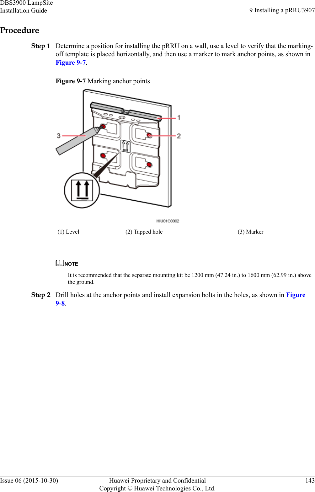
![lEven strength is applied when optical cables are coiled and optical cables cannot be bentin a forcible manner.lVacant optical connectors are covered with dust-proof caps.lFiber optic cables cannot be squeezed by the cabinet door when routed through thecabinet.lIf optical cables need to be routed on the tower platform, the optical cables are routedalong the inner side of the guard rail and the distance between the guard rail and thecable is the shortest one.lIf optical cables need to be routed close to a device on the tower, the optical cables aresecured to the guard rail or pole with cable clips and the device cannot be far away fromthe position for securing the optical cables.lIf the optical cable close to a device on the tower is too long, the optical cables arewrapped and secured to the tower.6.4.2 Cable ListThis section describes the connector types and connections of the RHUB cables.Table 6-3 lists RHUB cables.Table 6-3 RHUB cable listCable One End The Other EndConnector Connectedto...Connector Connected to...PGND cable OT terminal(M4, 6 mm2[0.009 in.2])Ground screwson the RHUBOT terminal(M6, 6 mm2[0.009 in.2])Ground terminalon the externalground barPowerSupply CableC13 femaleconnectorAC powerinput socket onthe RHUB3-pin connector External powerinput socketCPRI OpticalFiberDLC connector CPRI port onthe LBBP,WBBP orUBBP in theBBUDLC connector CPRI0 or CPRI1port on theRHUBCPRI port onthe LBBP,WBBP orUBBP in theBBUDLC connector CPRI port on theDCUCPRI port onthe DCUCPRI0 or CPRI1port on theRHUBDBS3900 LampSiteInstallation Guide 6 Installing an RHUBIssue 06 (2015-10-30) Huawei Proprietary and ConfidentialCopyright © Huawei Technologies Co., Ltd.35](https://usermanual.wiki/Huawei-Technologies/PRRU3901B2B5/User-Guide-2847188-Page-41.png)
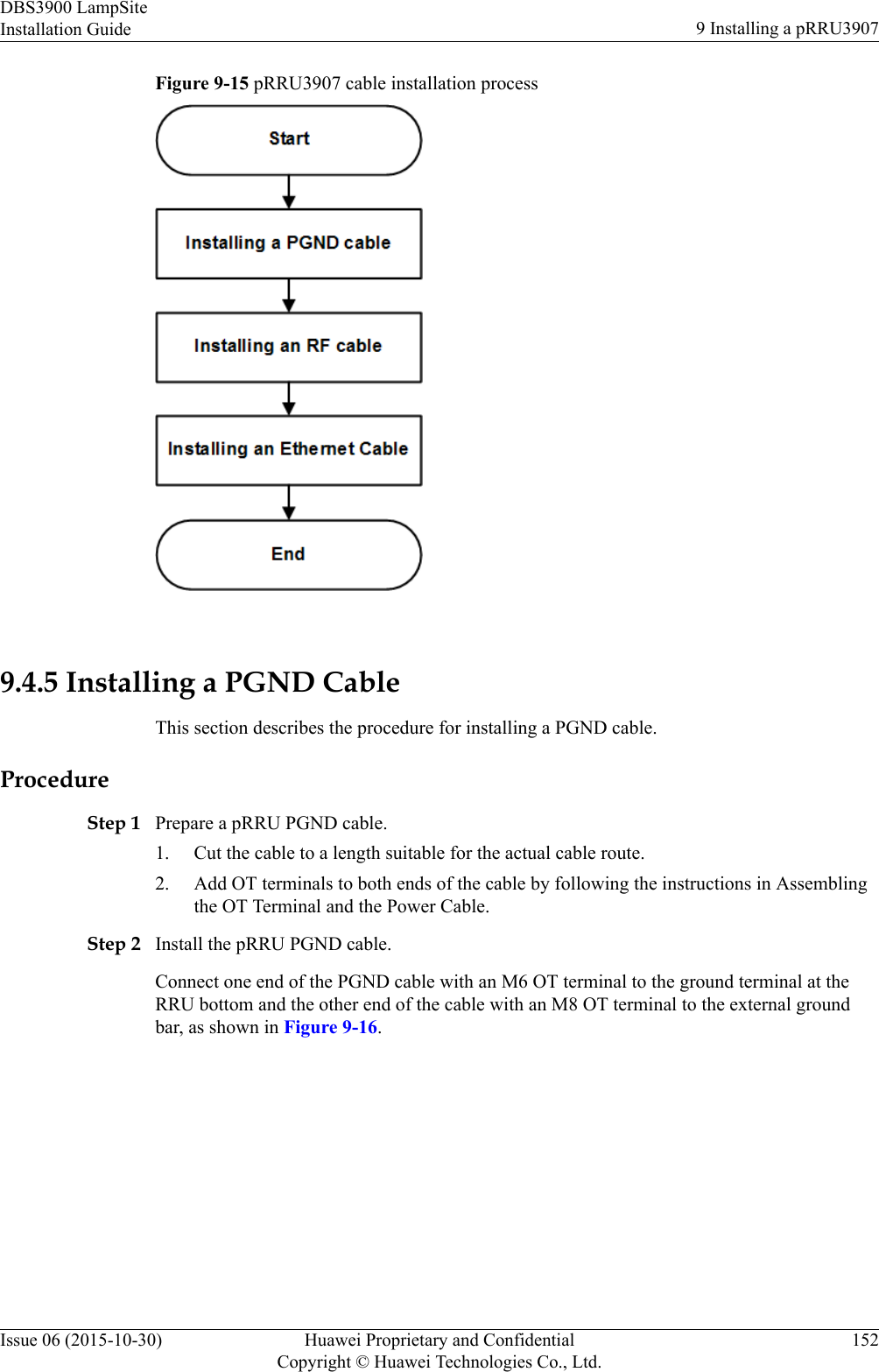
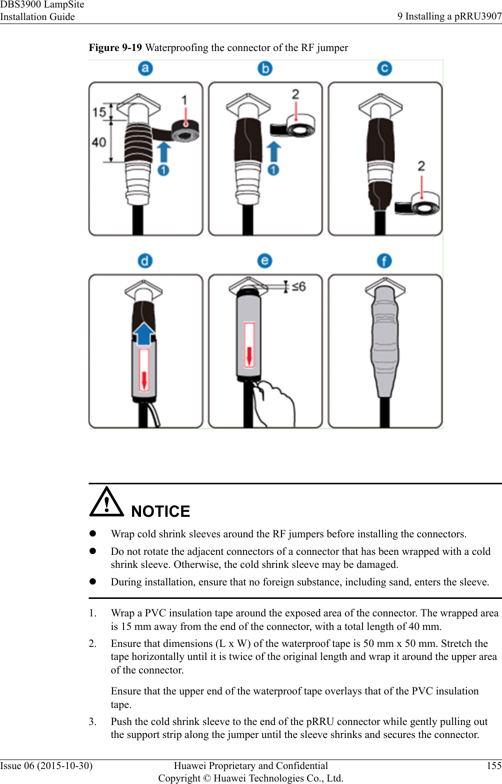
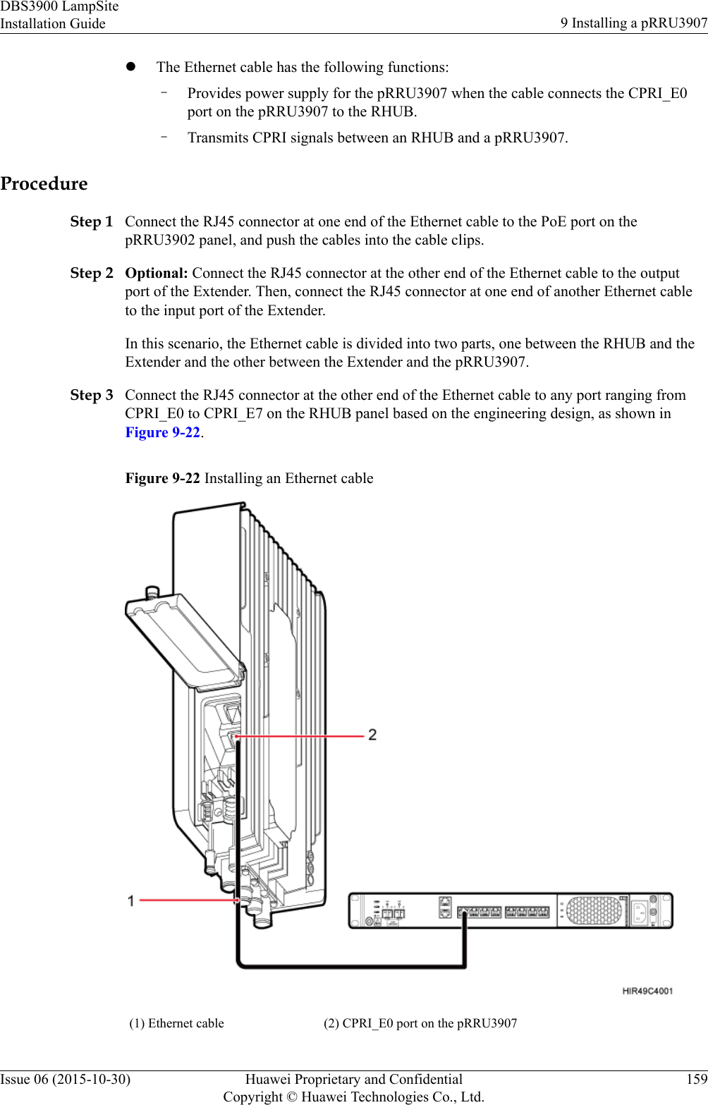
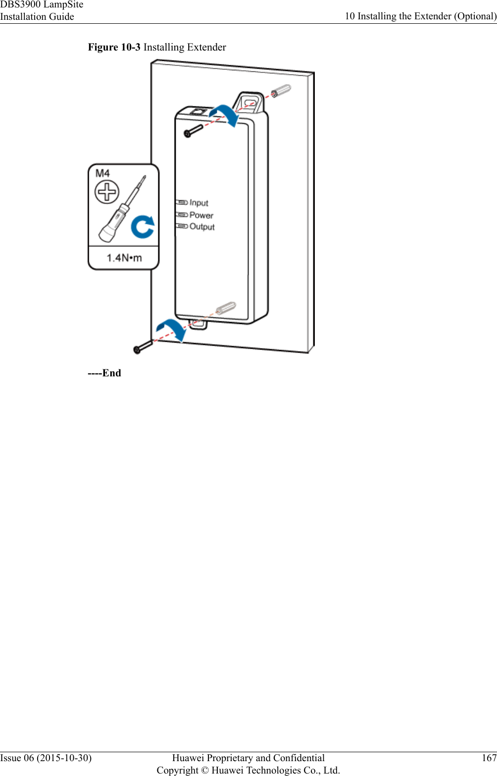
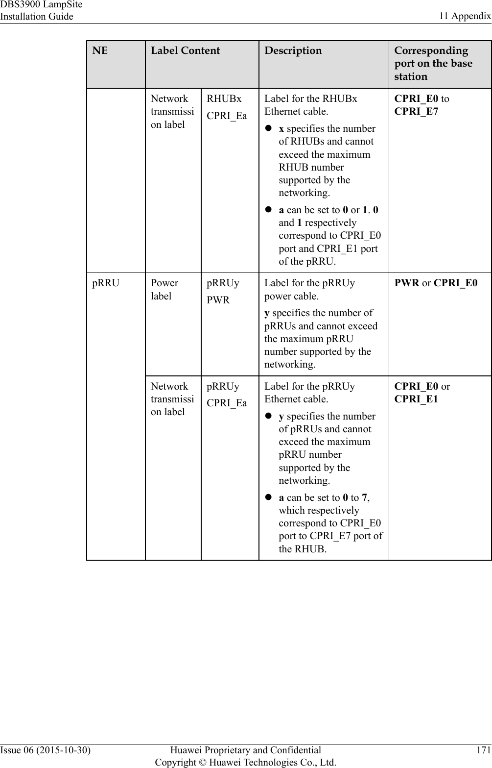
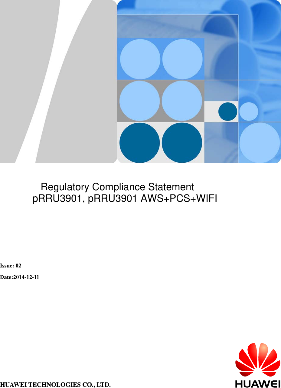
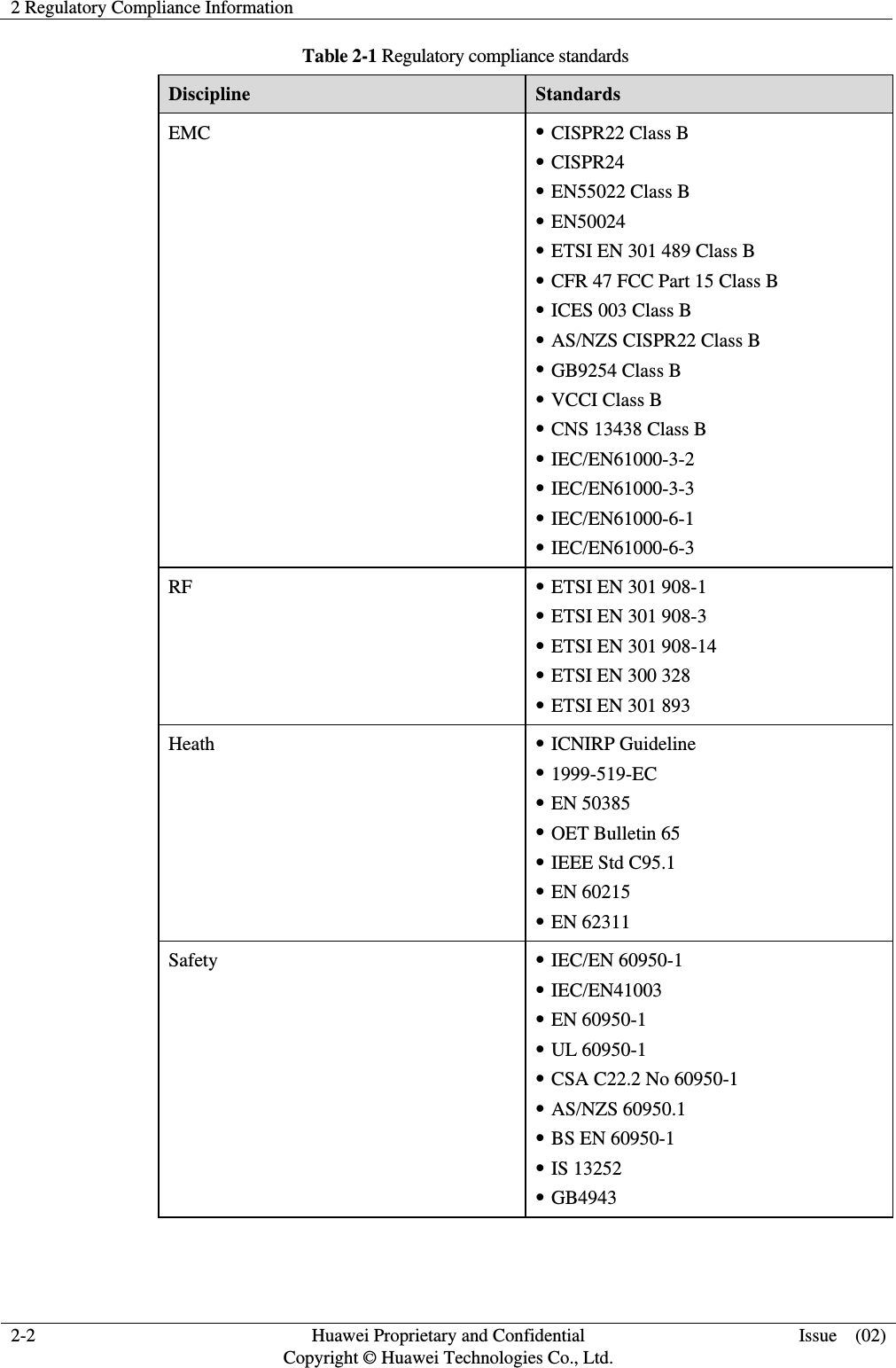
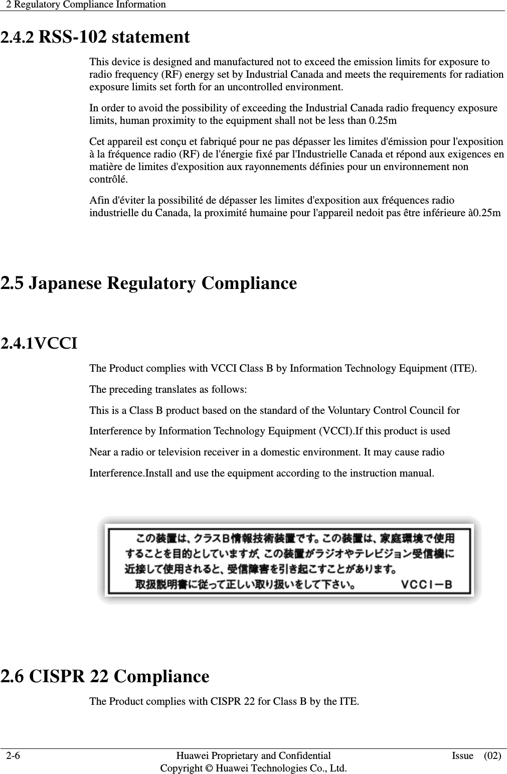
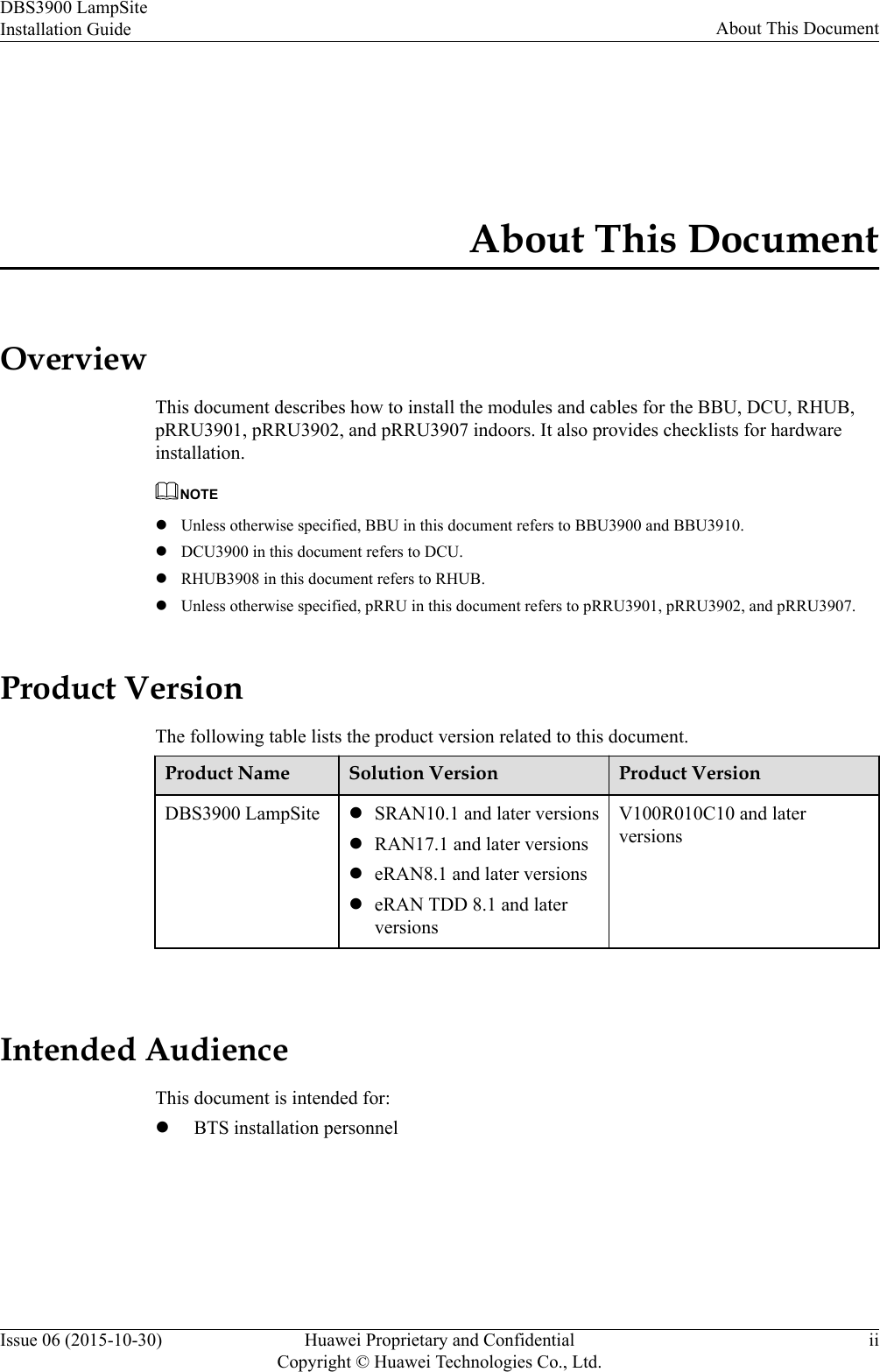
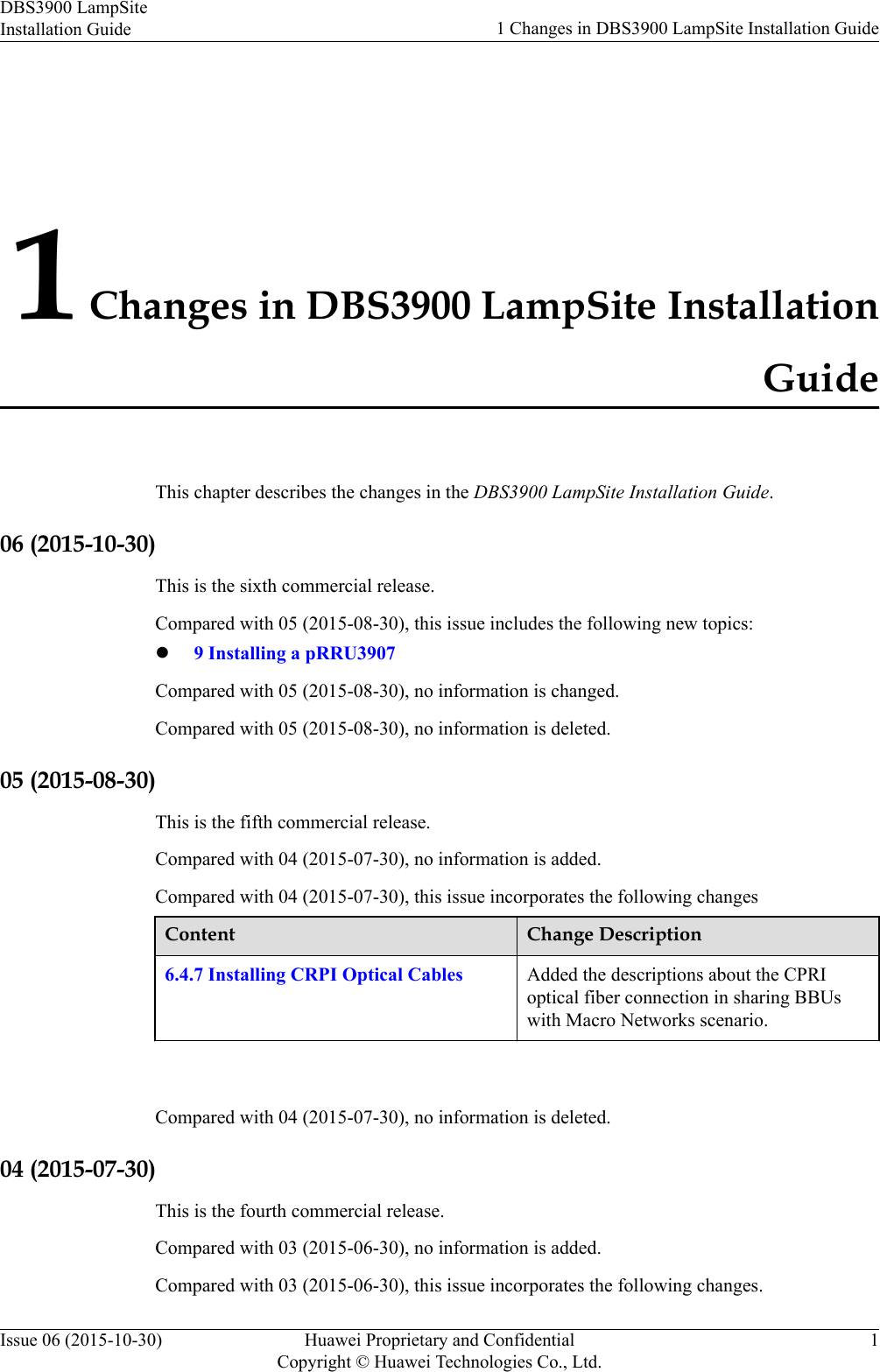
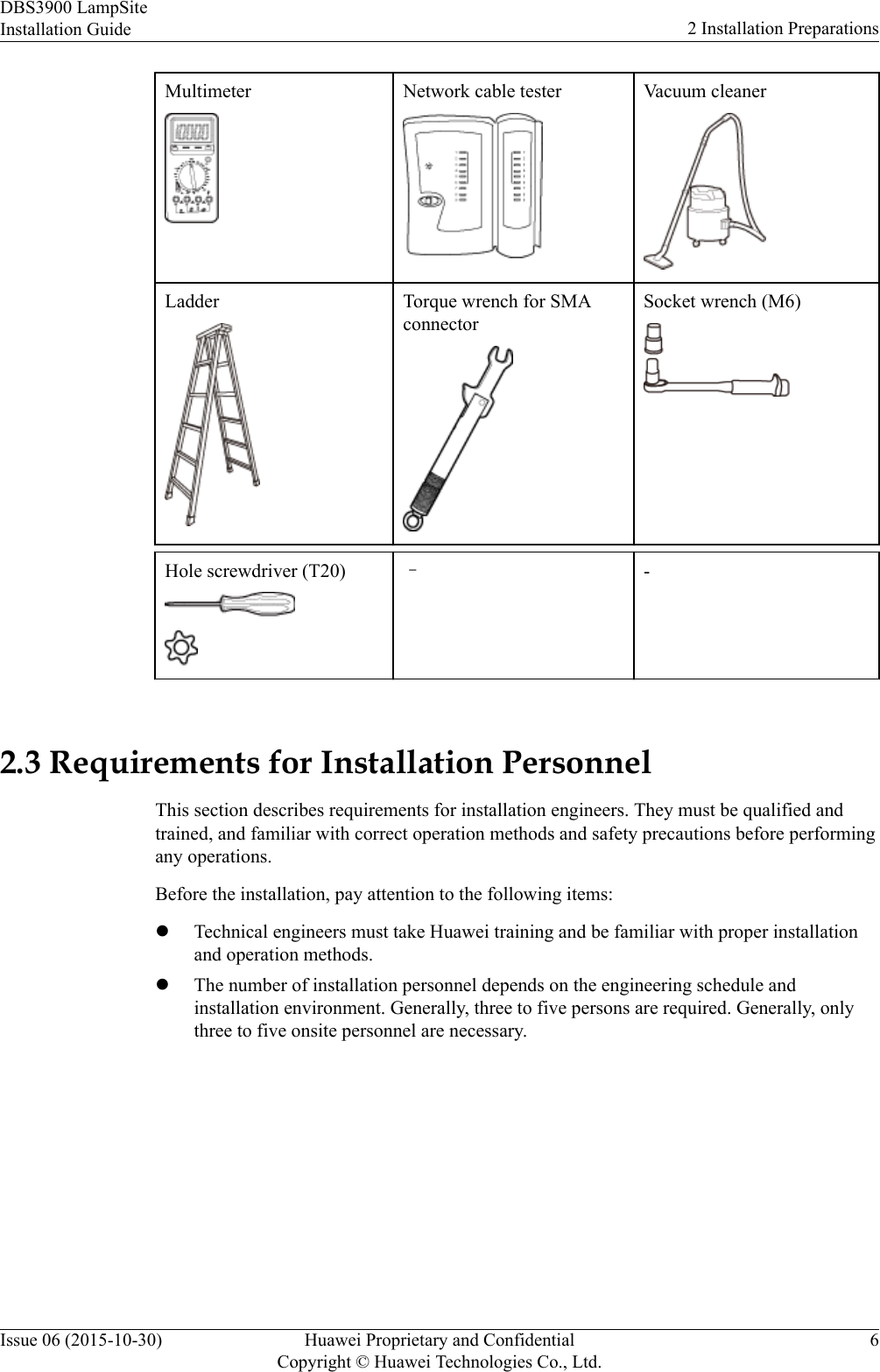
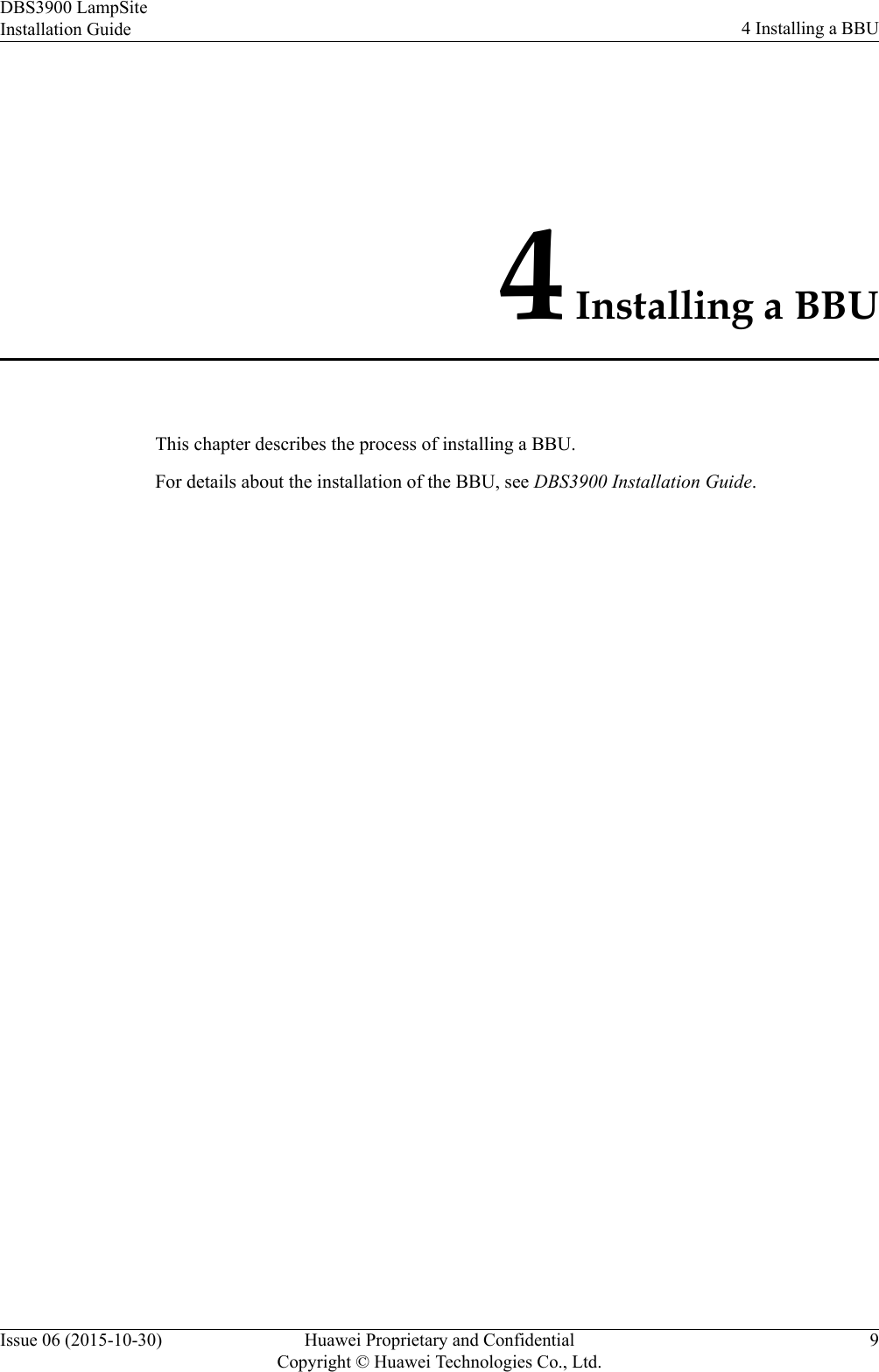
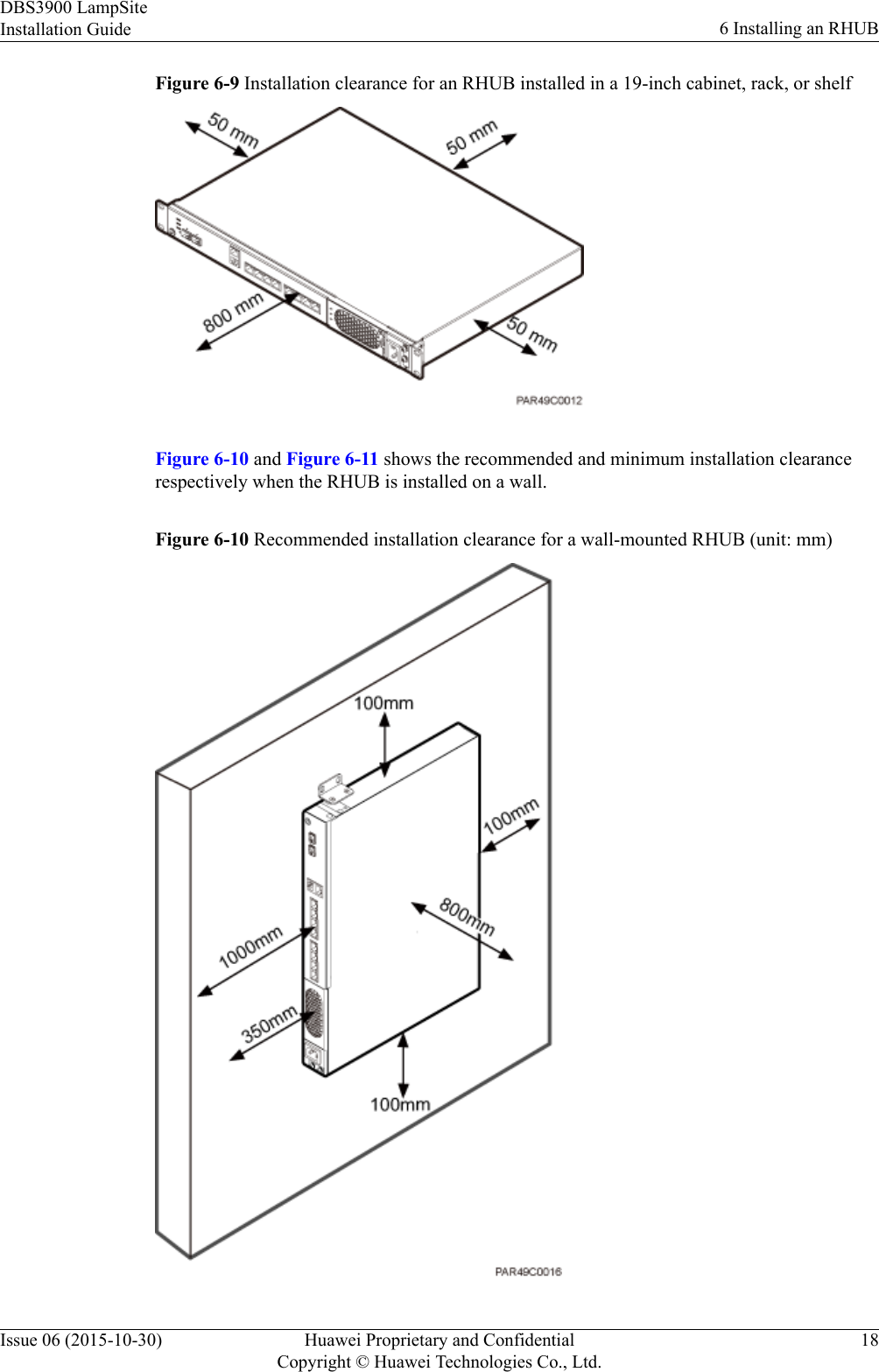
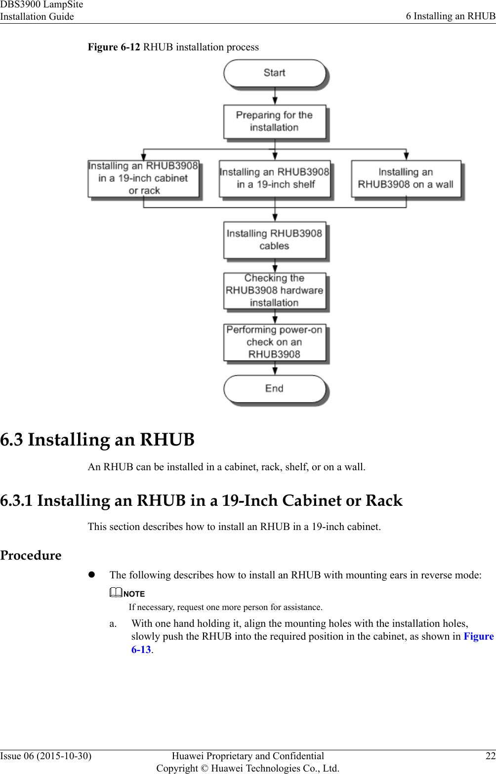
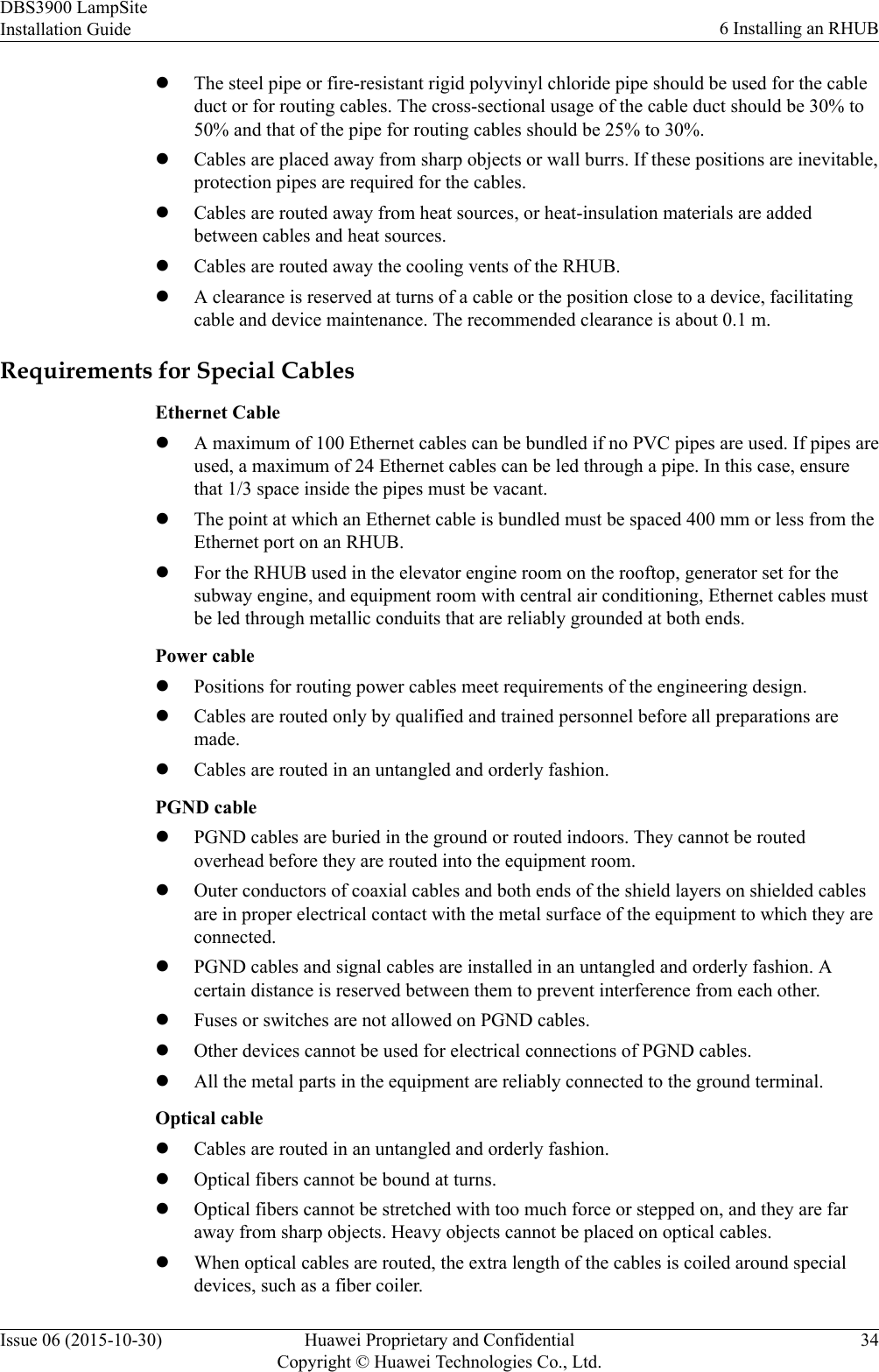
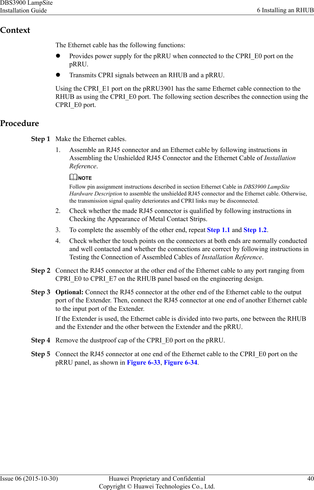
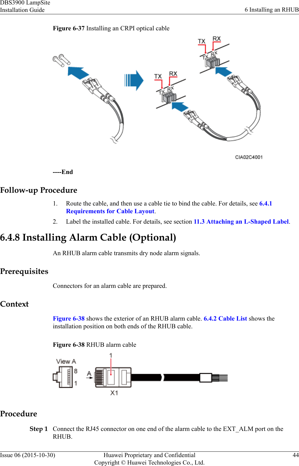
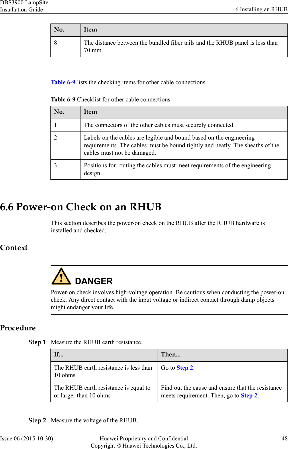
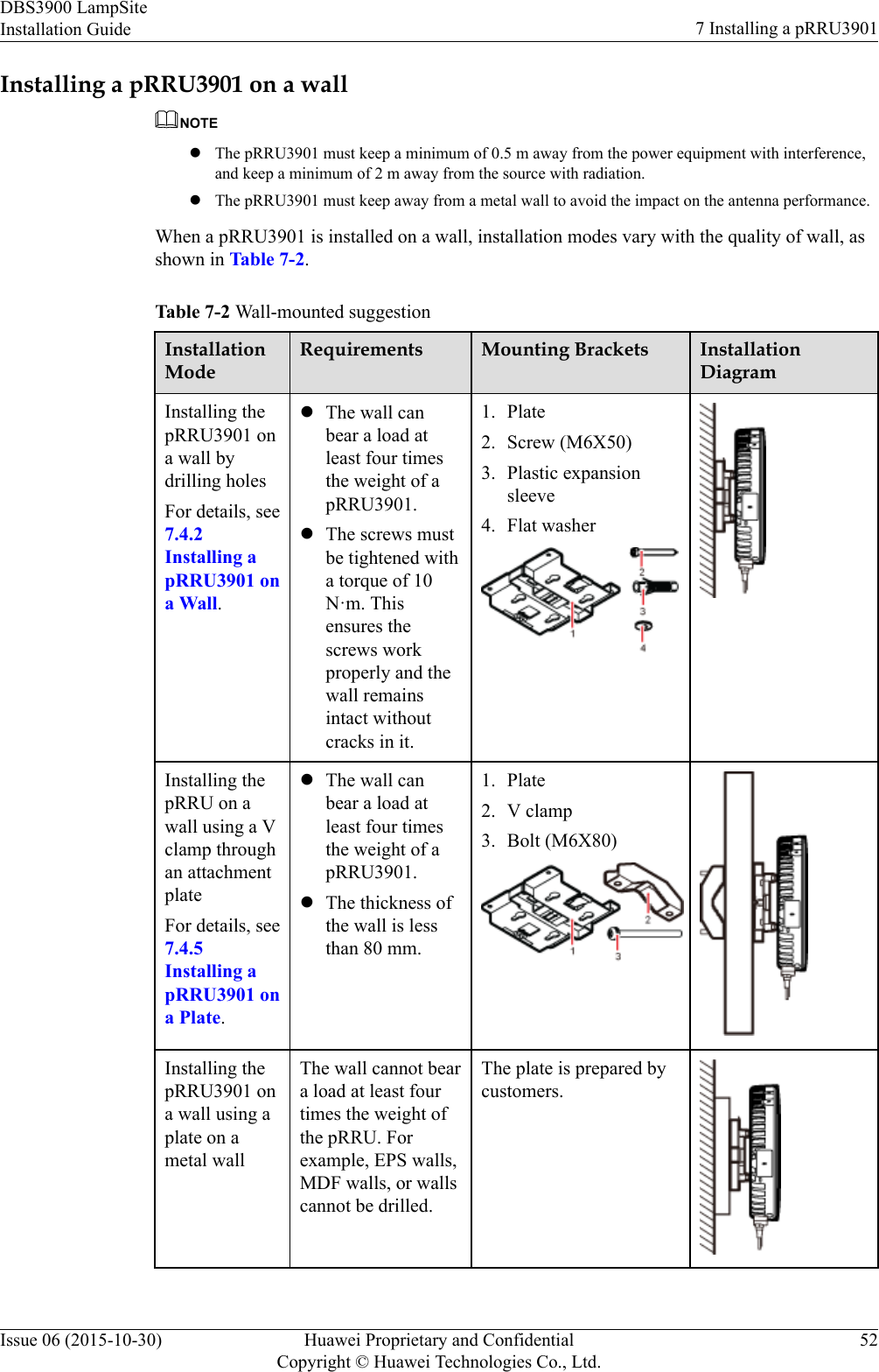
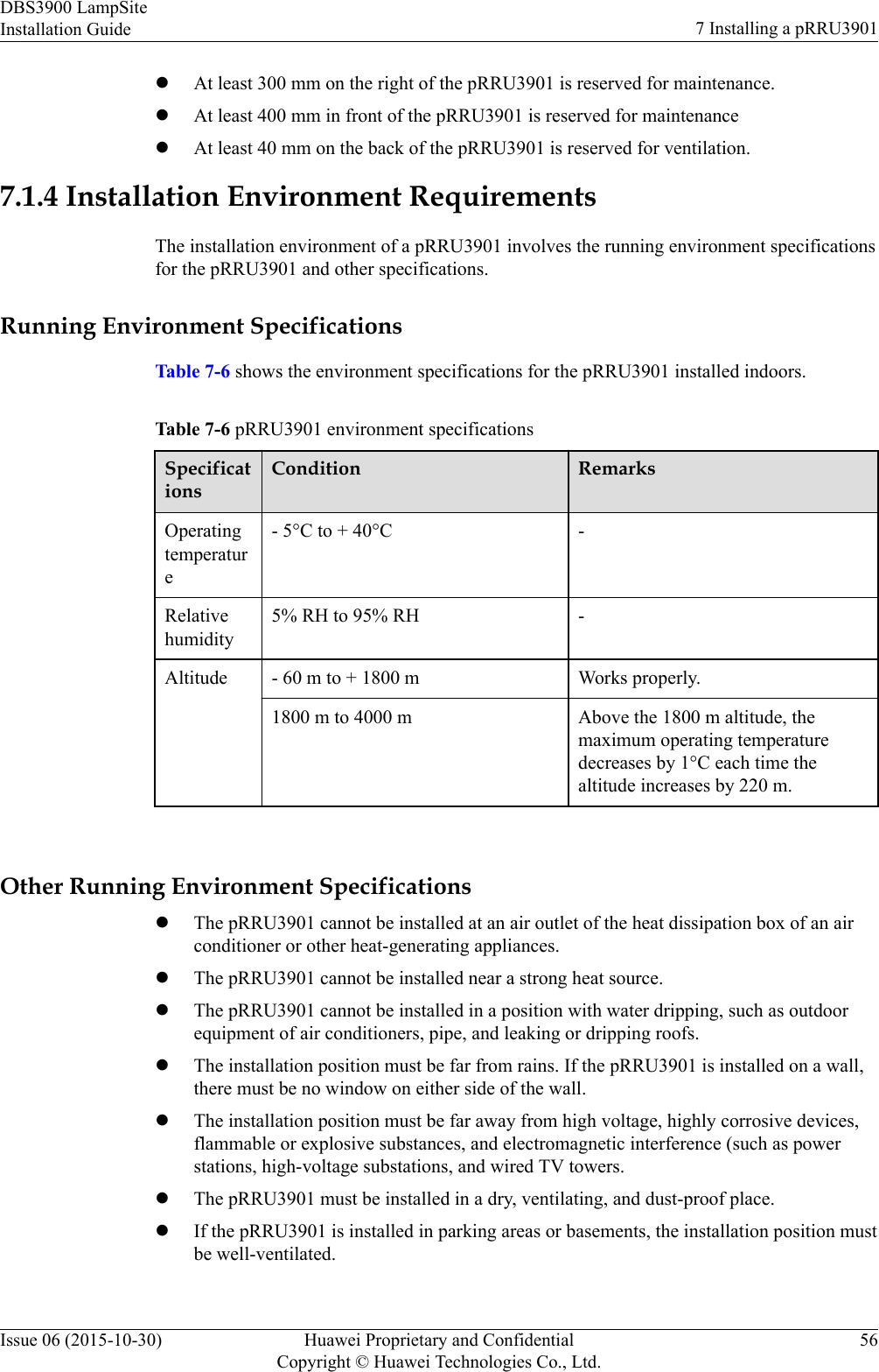
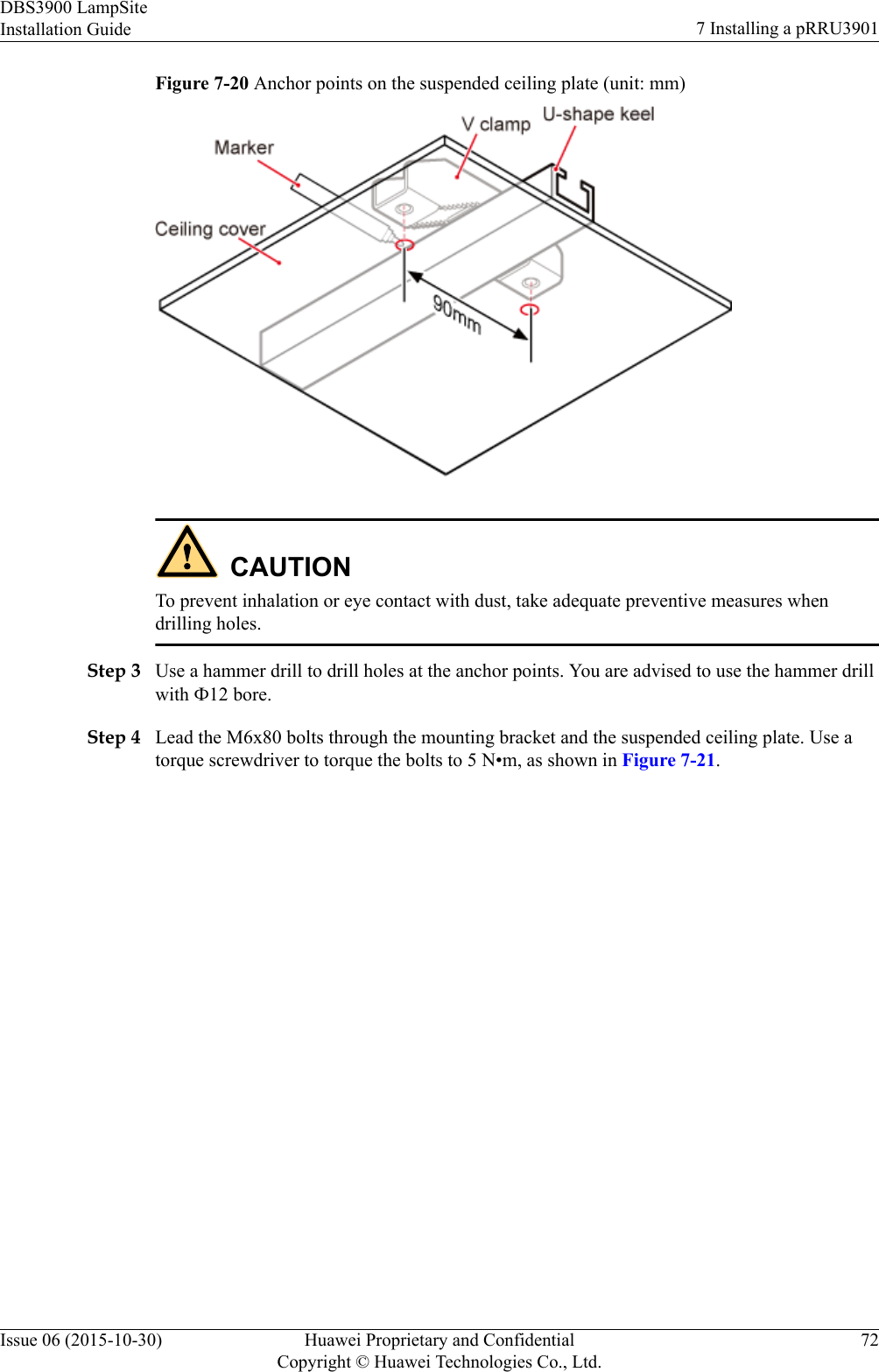
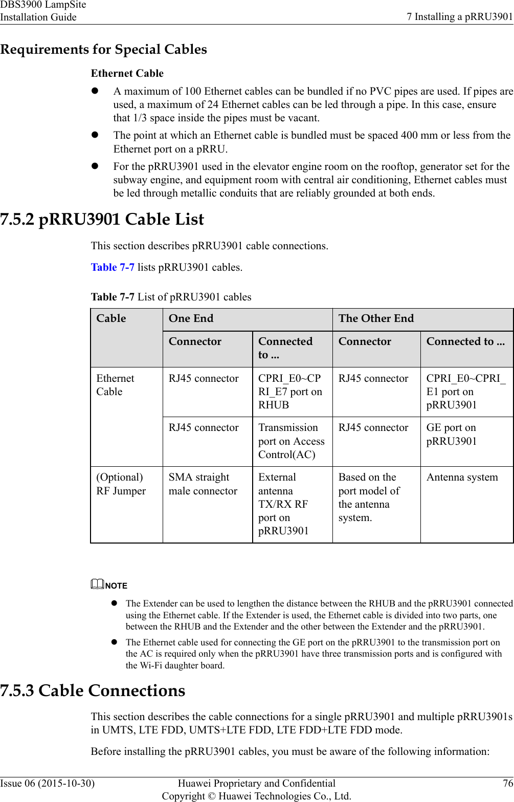
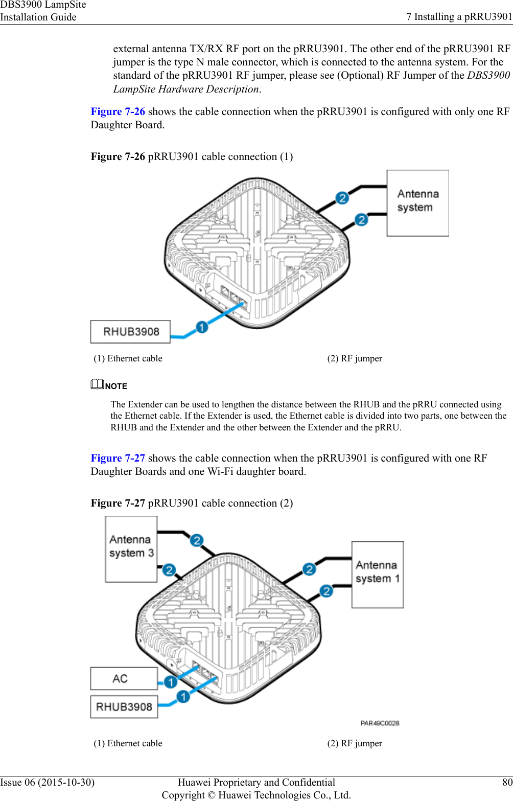
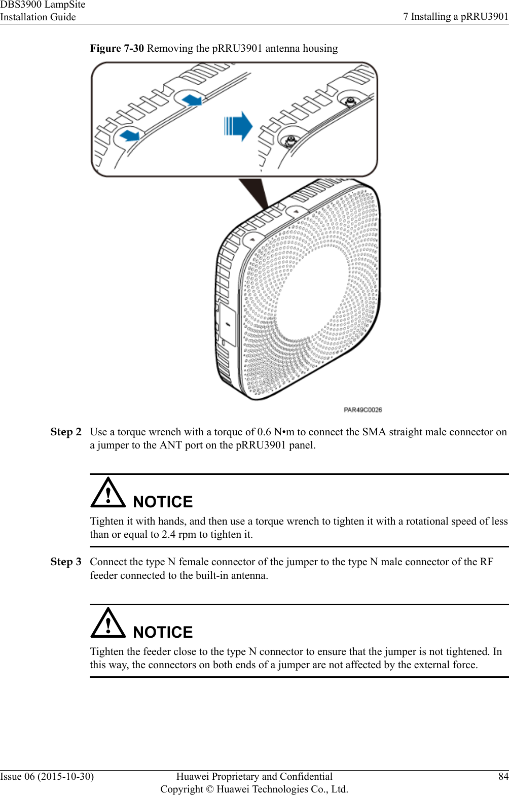
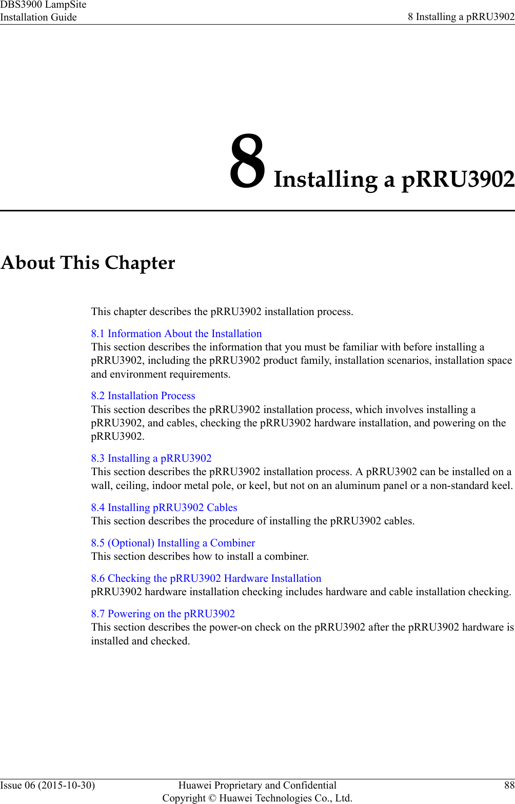
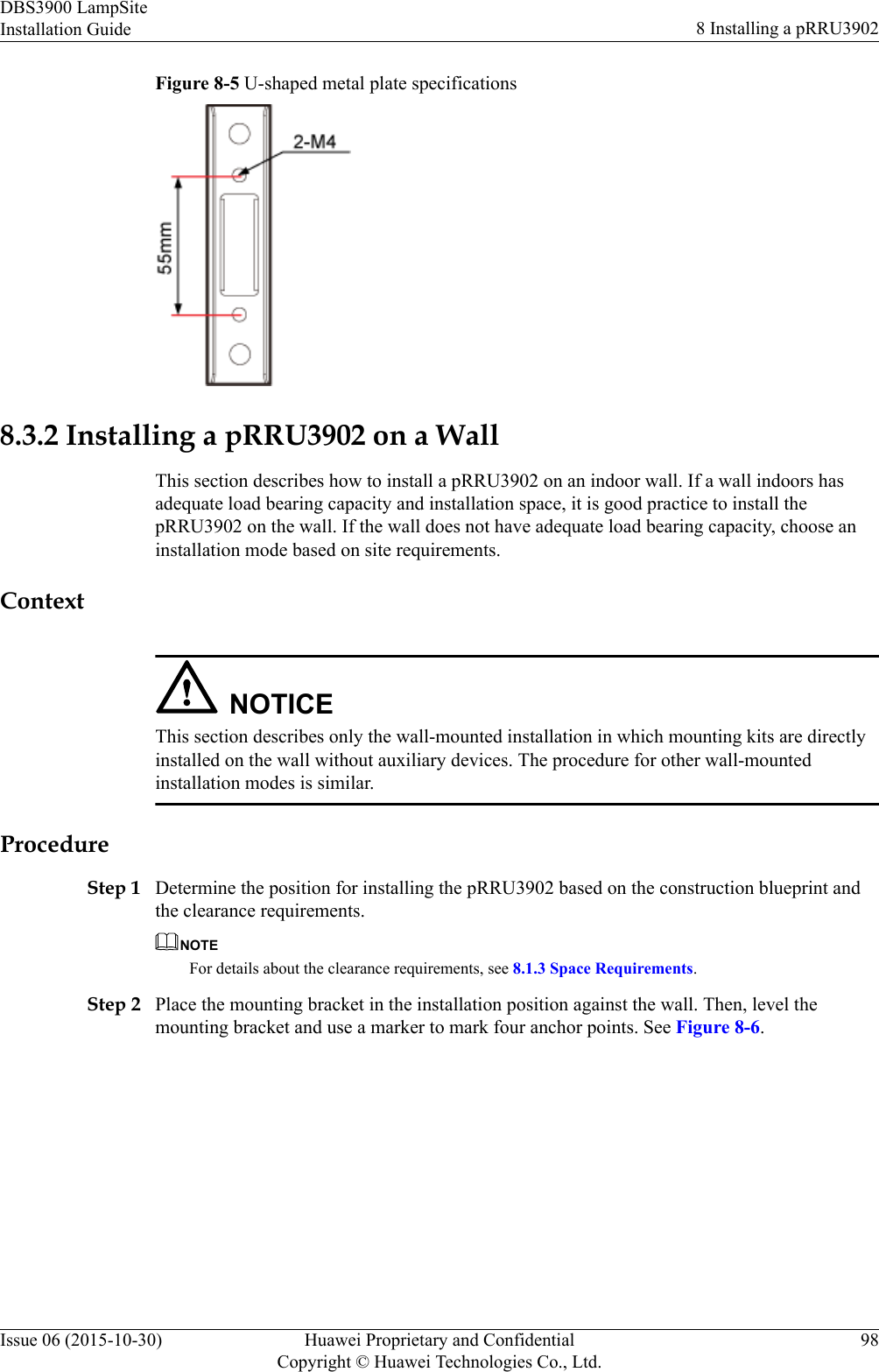
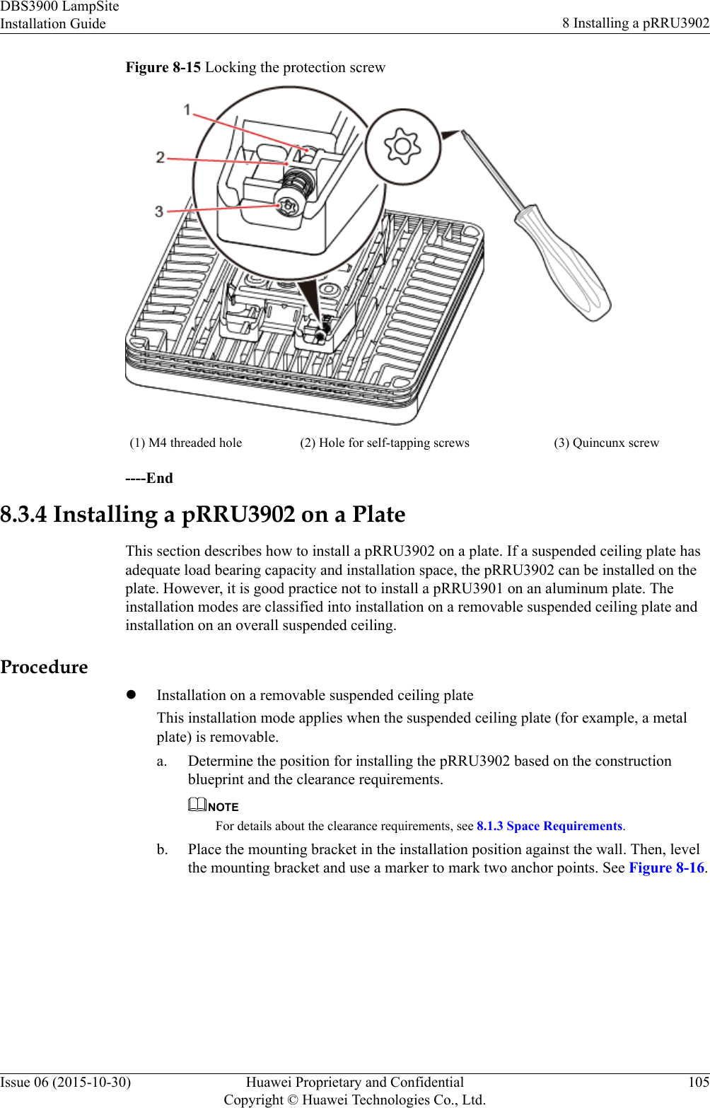
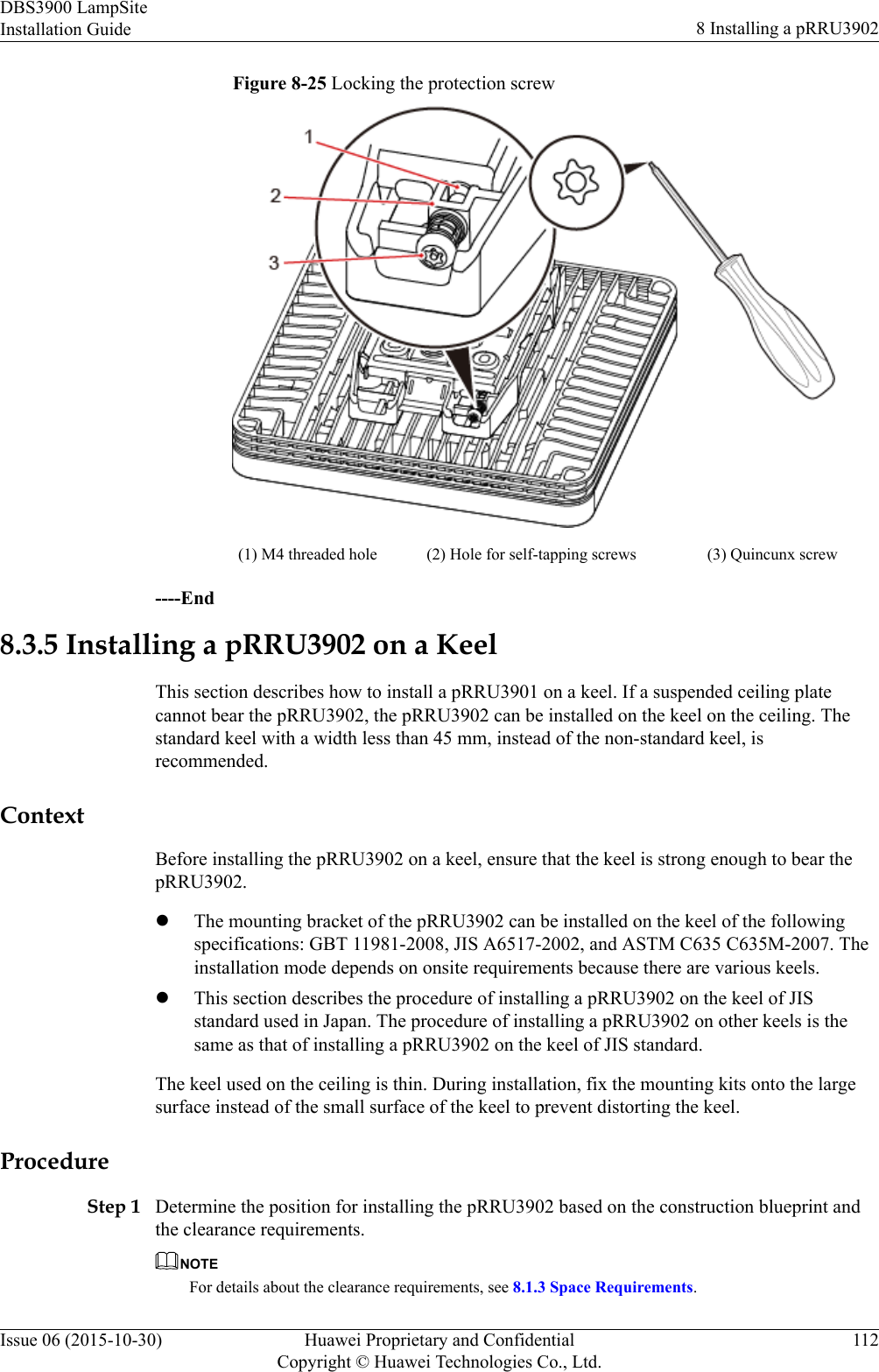
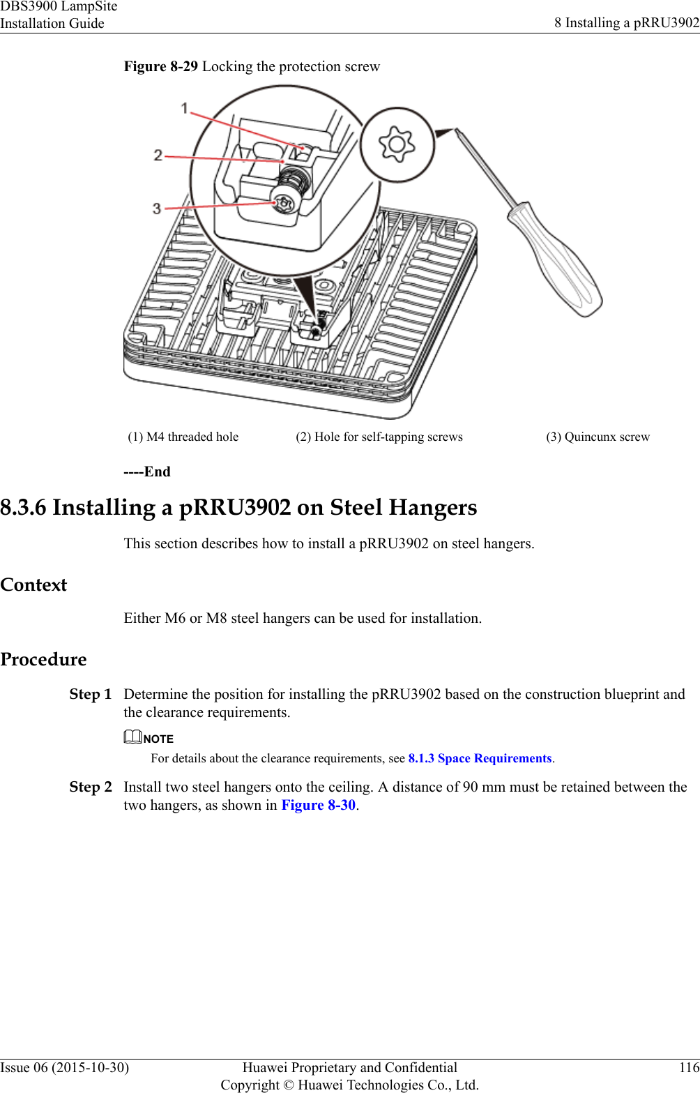
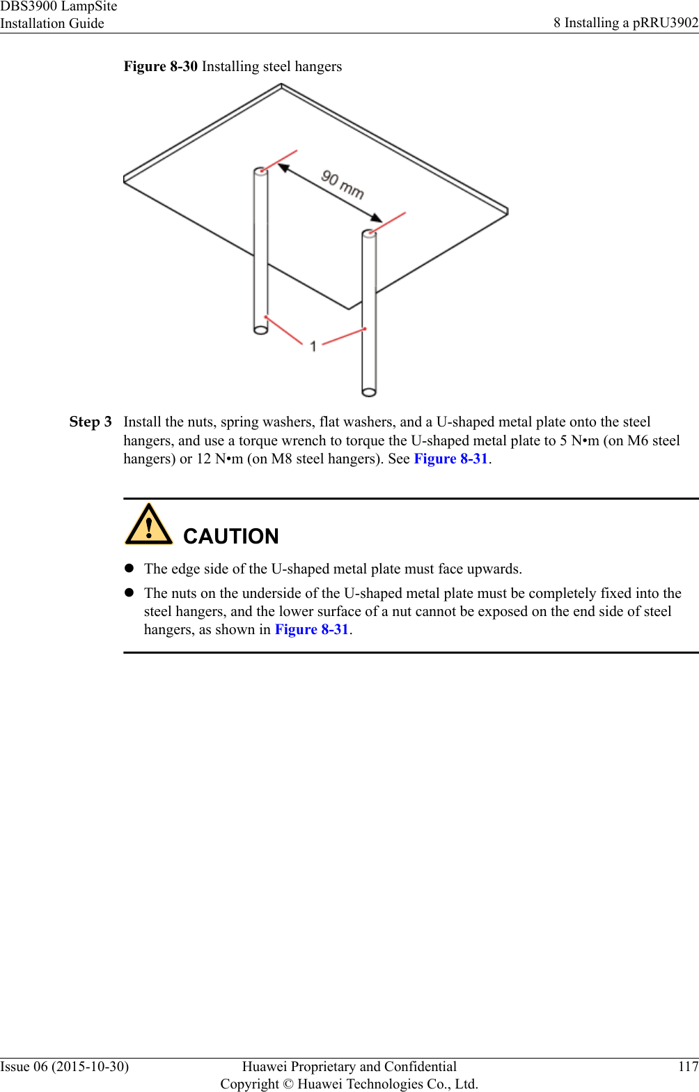
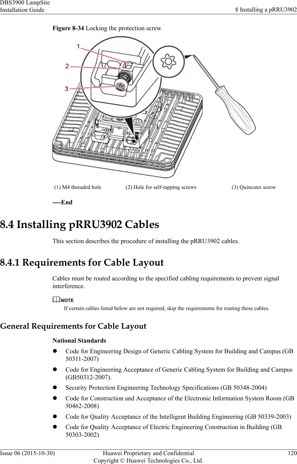
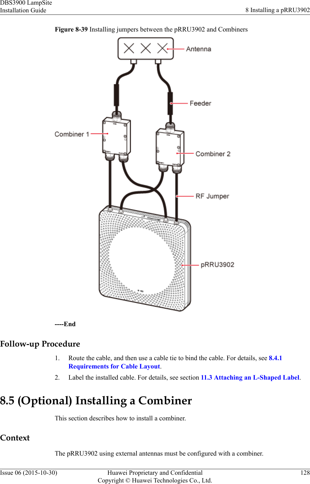
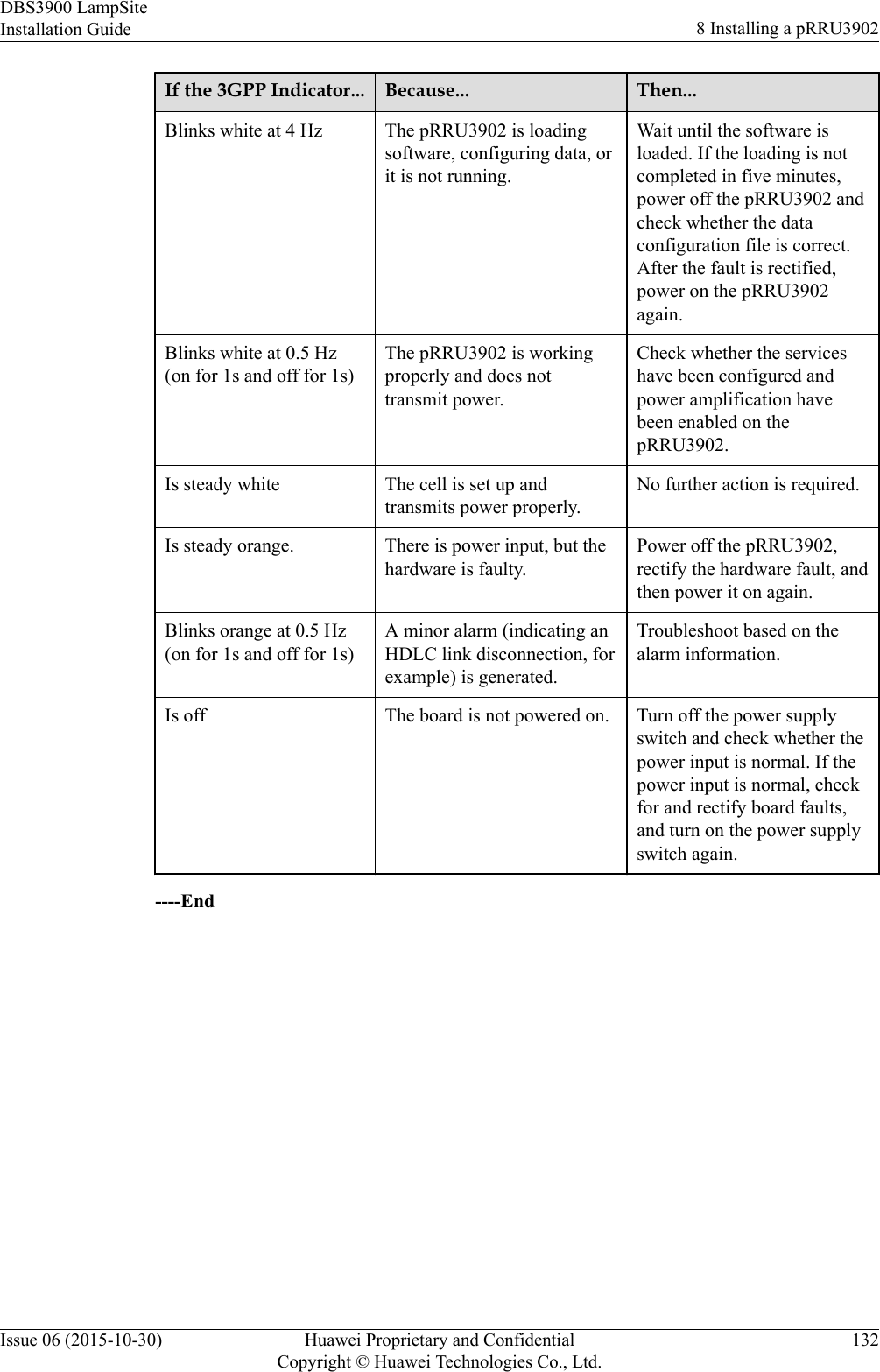
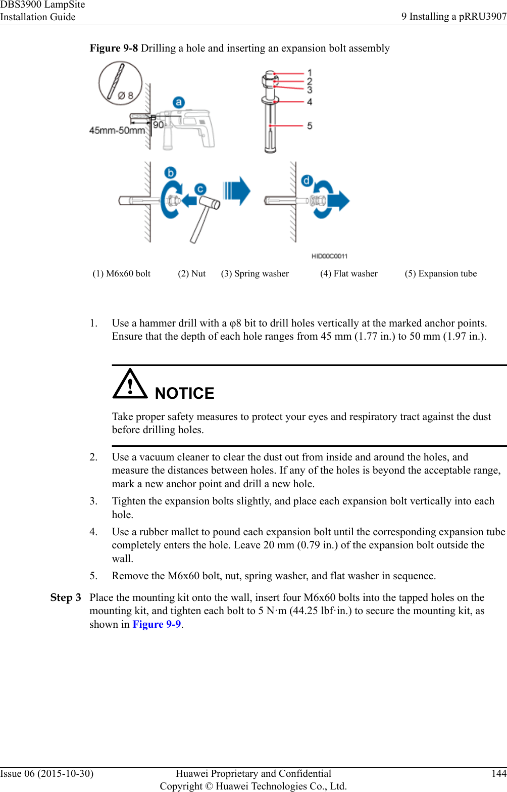
![6.4.5 Installing PGND CableAn RHUB PGND cable ensures proper grounding of an RHUB.PrerequisitesThe OT terminals at both ends of the PGND cable are prepared.ContextThe yellow and green or green PGND cable is a single cable. The cross-sectional area of thePGND cable is 6 mm2 (0.009 in.2). Both ends of the cable are OT terminals, as shown inFigure 1.Figure 6-30 Exterior of a PGND cable(1) OT terminal (6 mm2 [0.009 in.2], M4) (2) OT terminal (6 mm2 [0.009 in.2], M6)NOTElIf the PGND cable is provided by the customer, a copper-core cable with a minimum cross-sectionalarea of 6 mm2 (0.009 in.2) or 10 AWG is recommended.lThe OT terminals at both ends of the PGND cable are assembled at the site.lThe M6 OT terminal has the default size. You can replace it with another OT terminal of theexpected size based on the site requirement. NOTICElEnsure proper grounding of the RHUB using a PGND cable.lWhen installing the PGND cable, tightly press the OT terminal in the correct direction, asshown in Figure 6-31.Figure 6-31 Correct direction of an OT terminal for the PGND cableDBS3900 LampSiteInstallation Guide 6 Installing an RHUBIssue 06 (2015-10-30) Huawei Proprietary and ConfidentialCopyright © Huawei Technologies Co., Ltd.38](https://usermanual.wiki/Huawei-Technologies/PRRU3901B2B5/User-Guide-2847188-Page-44.png)
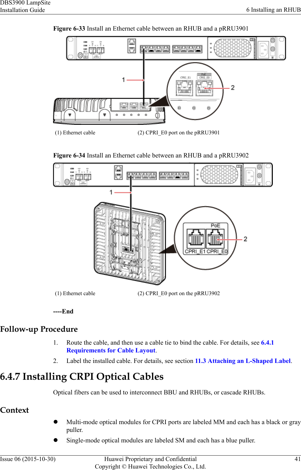
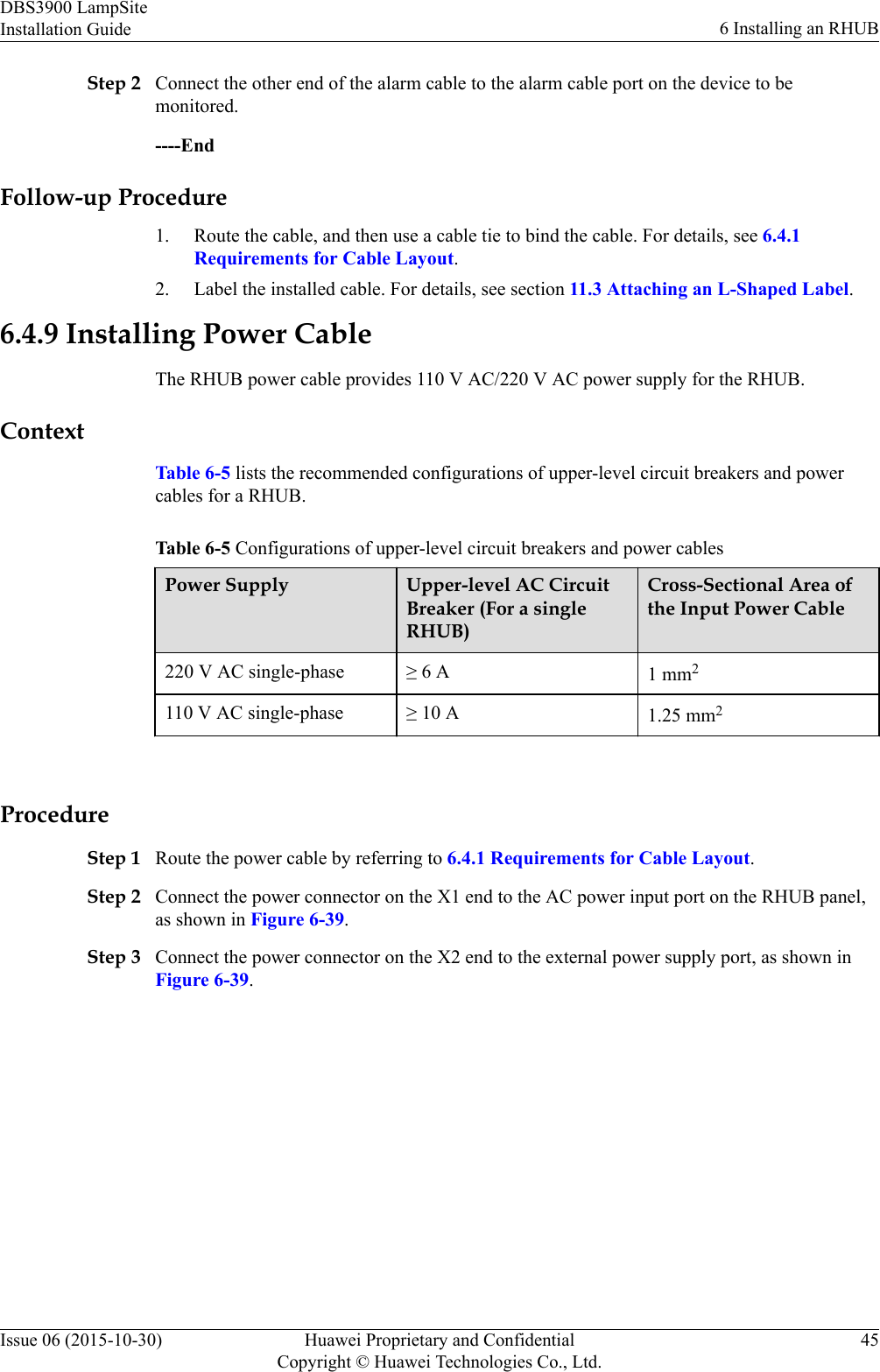
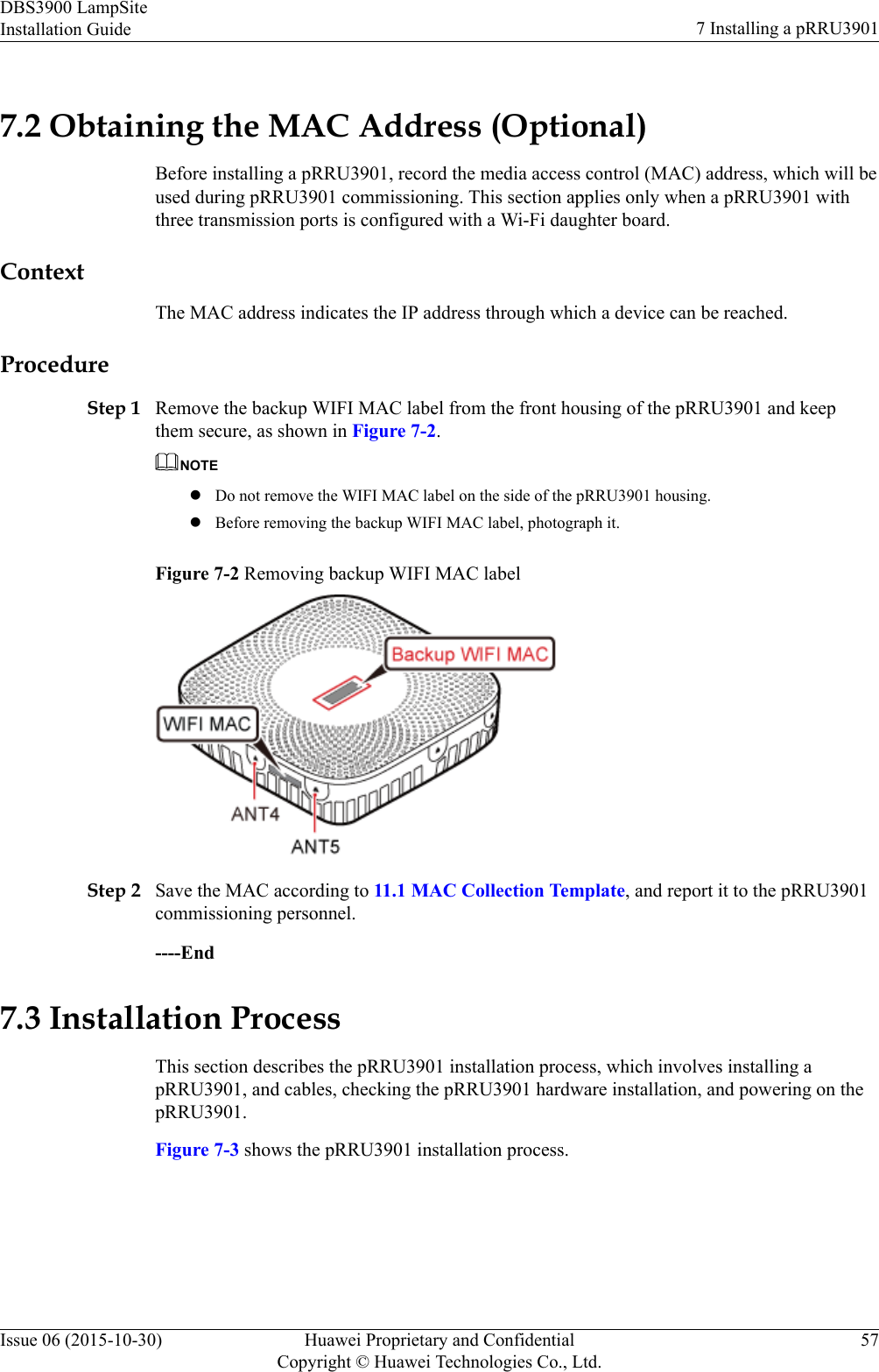
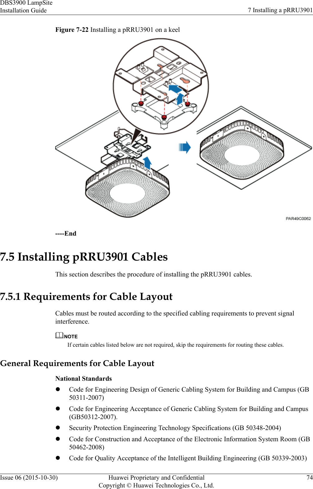
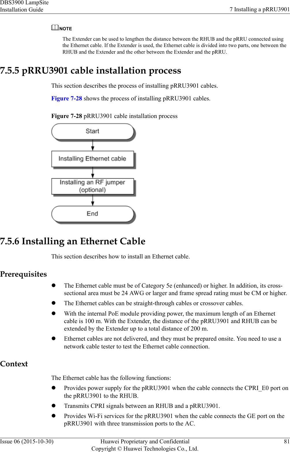
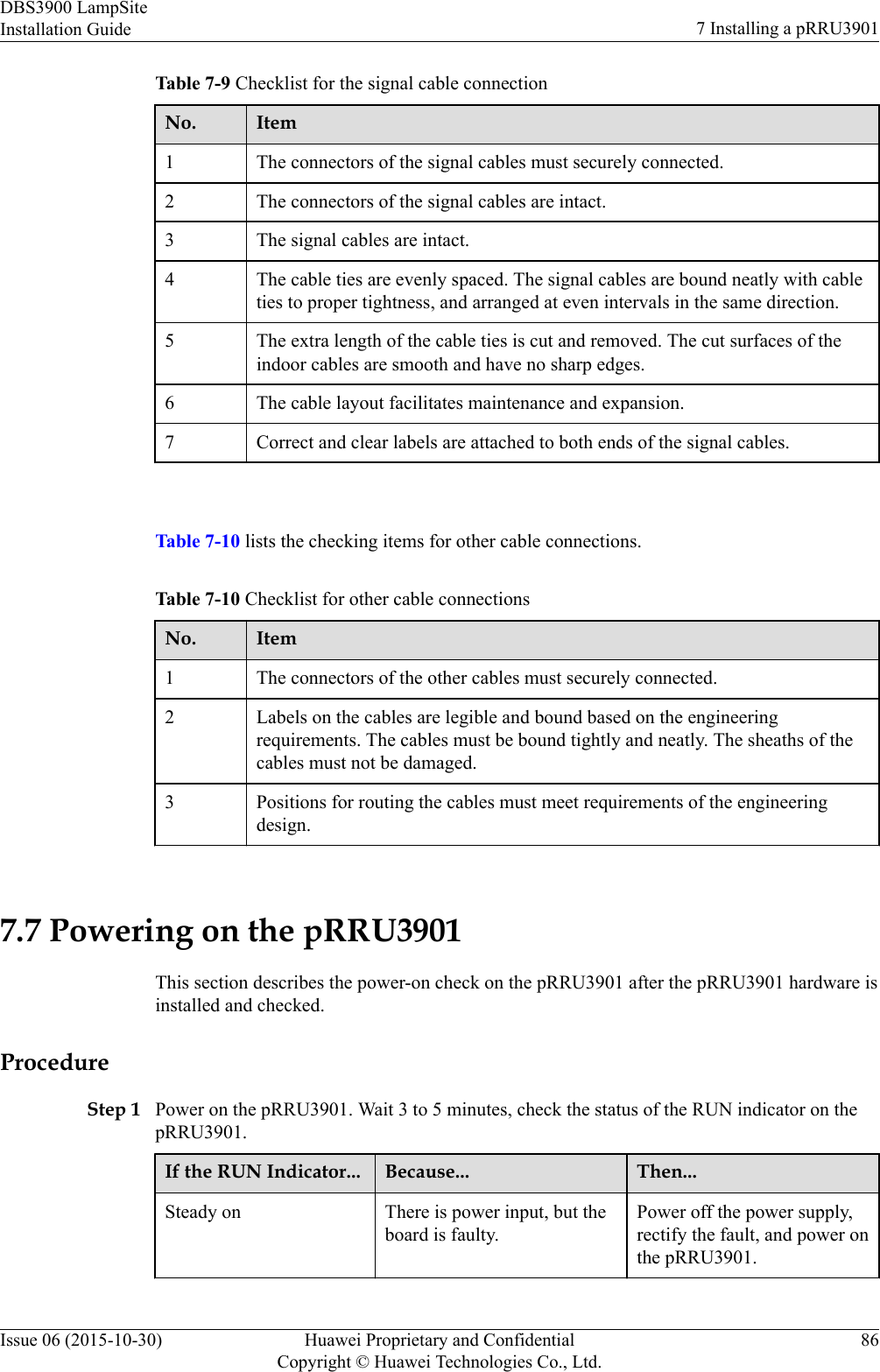
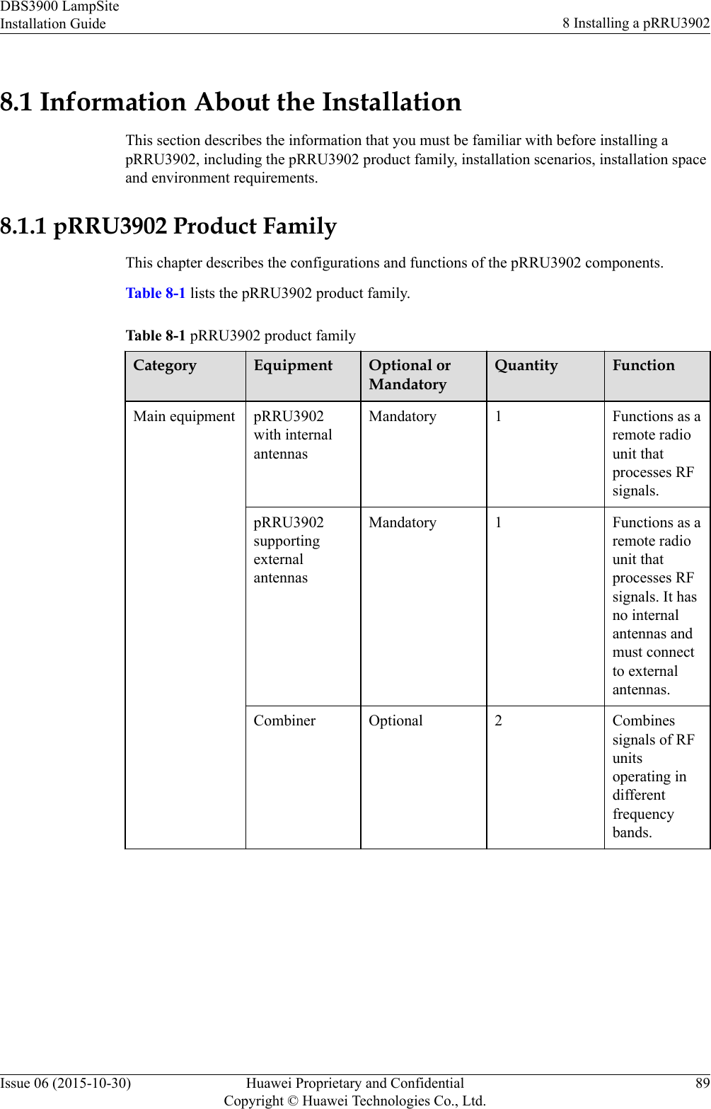
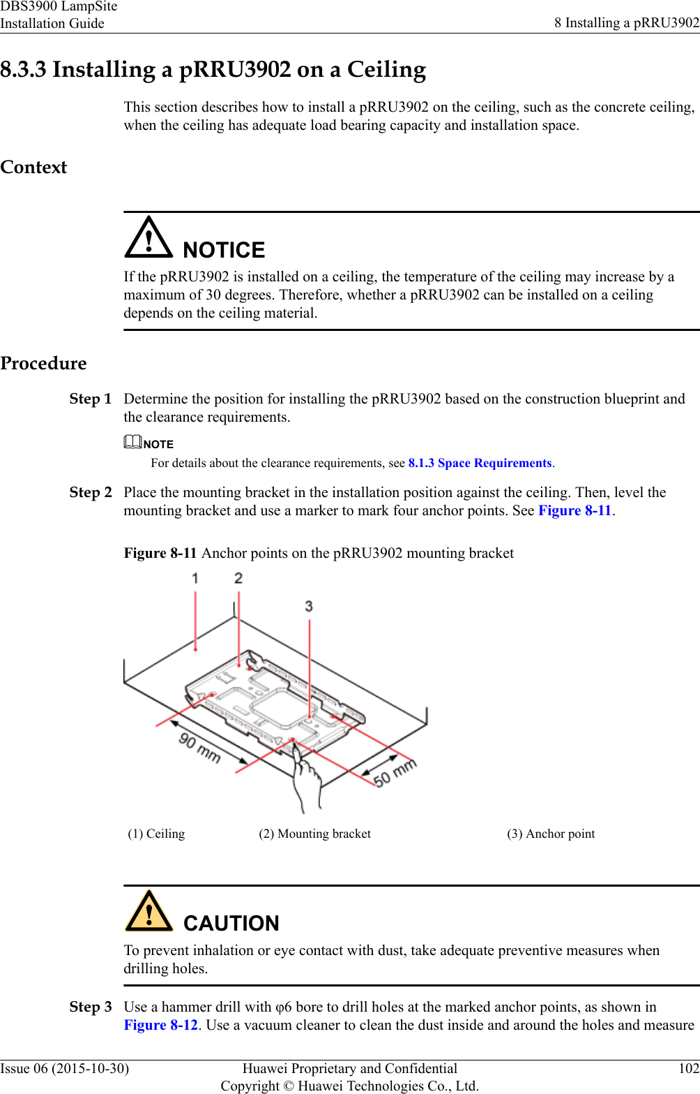
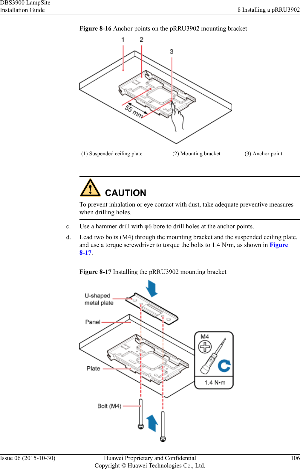
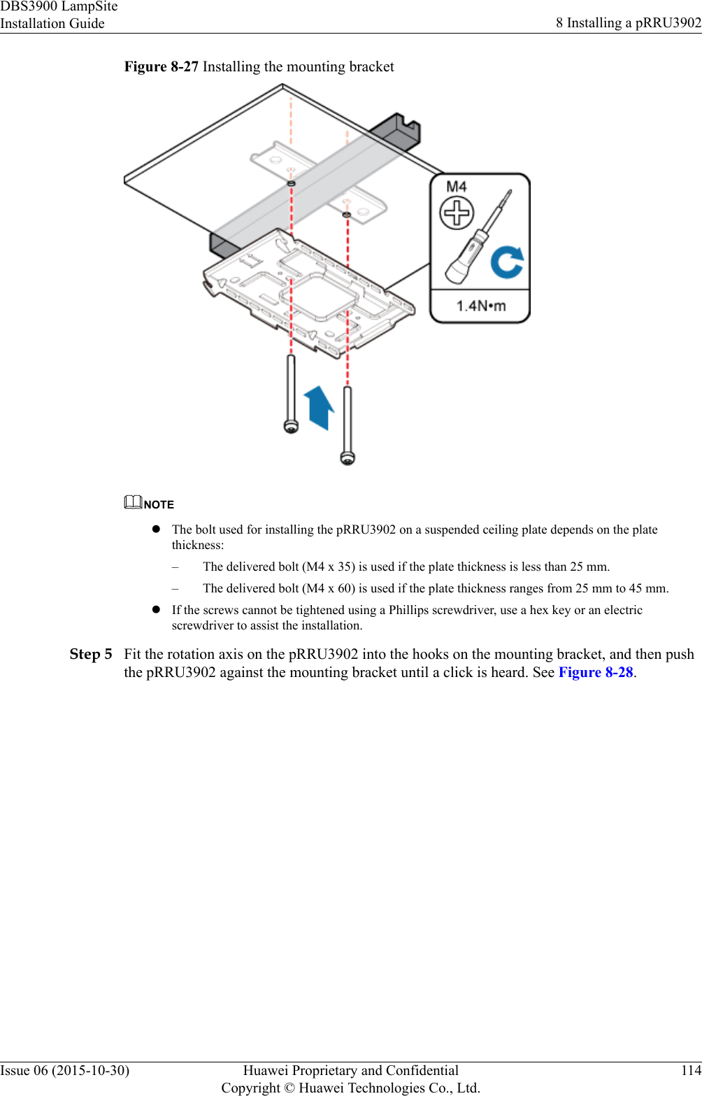
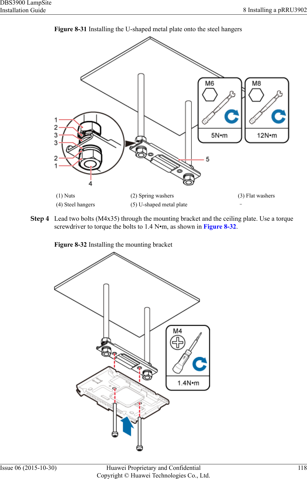
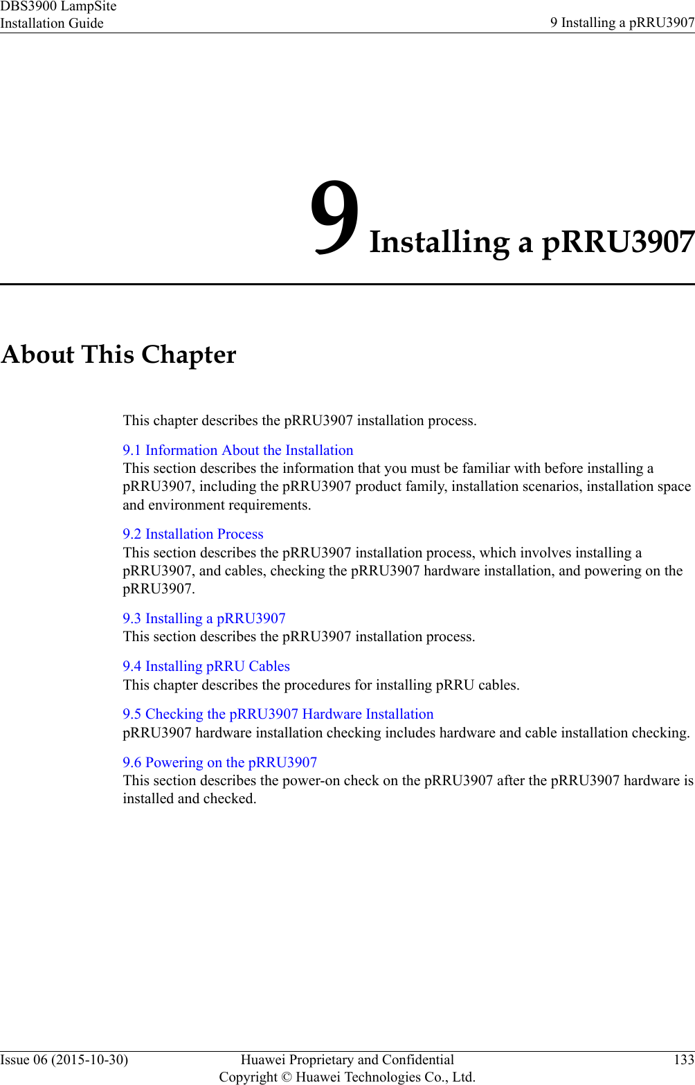
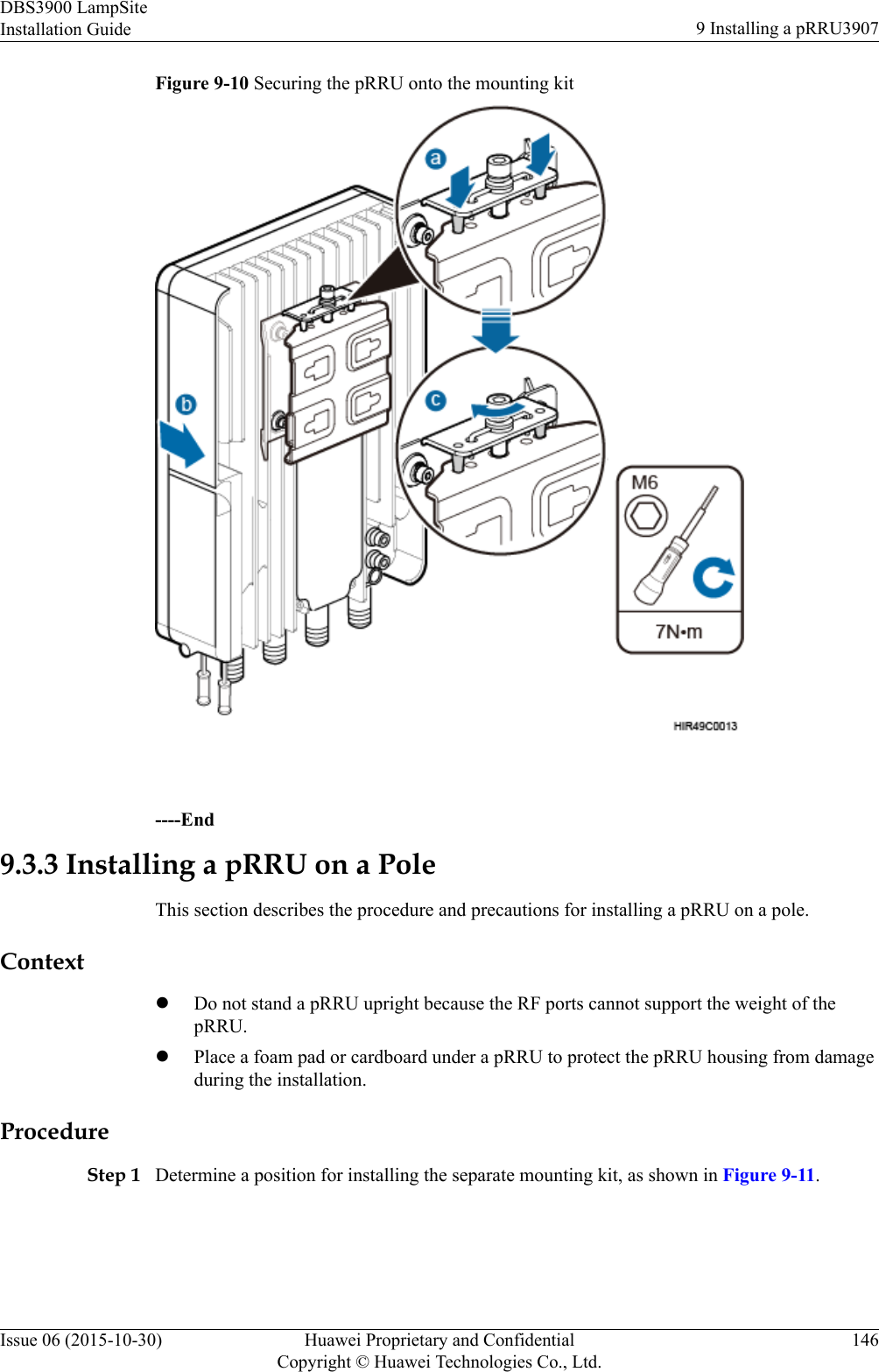
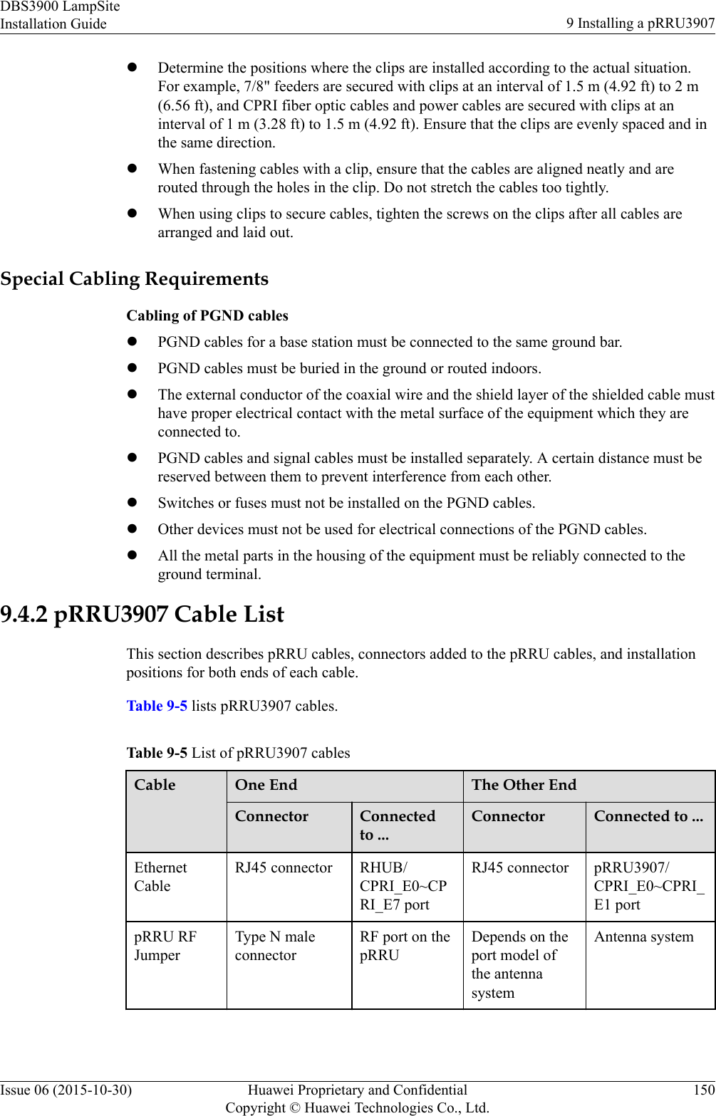
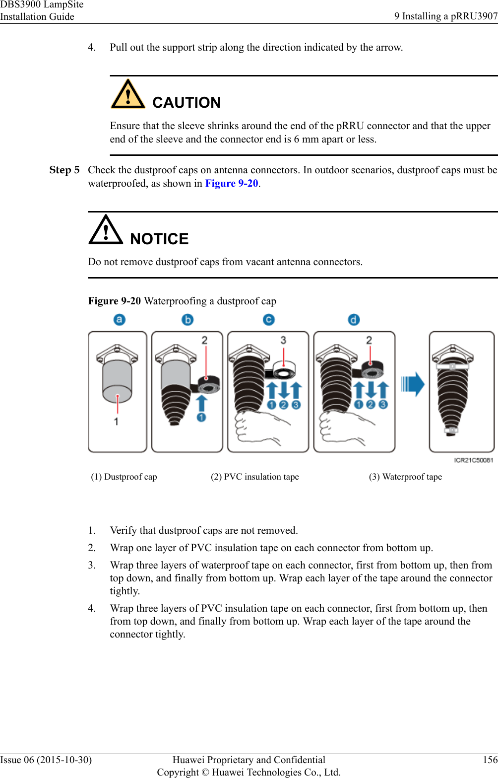
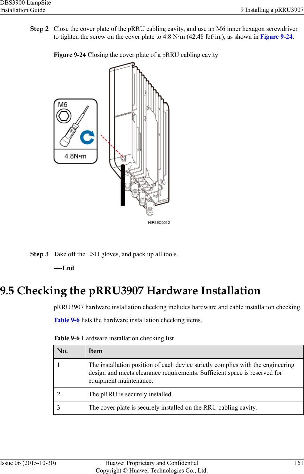
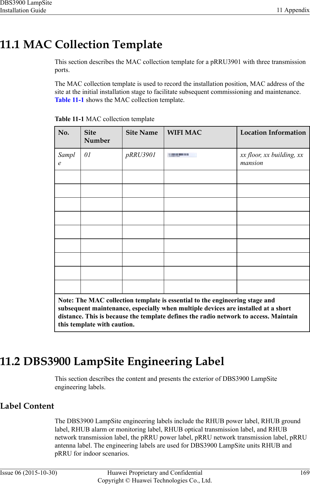
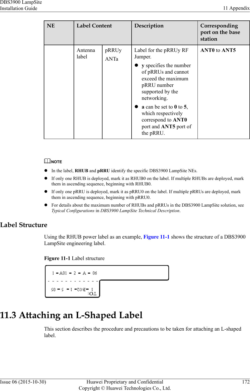
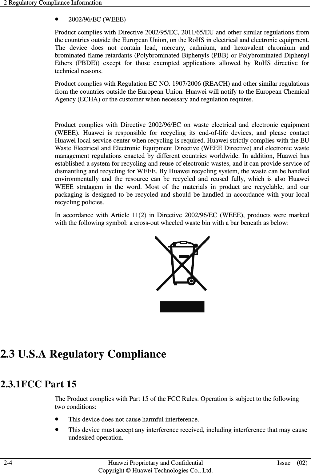
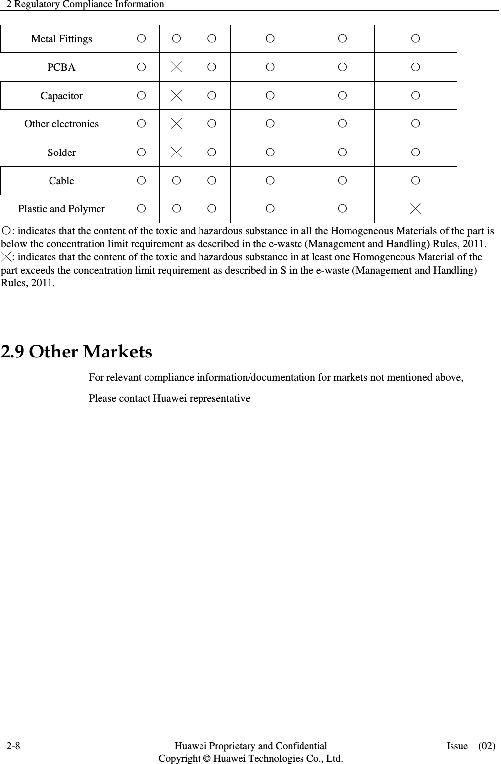
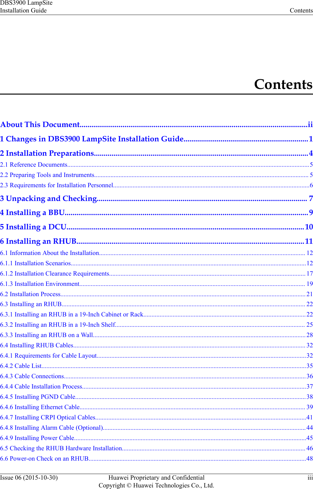
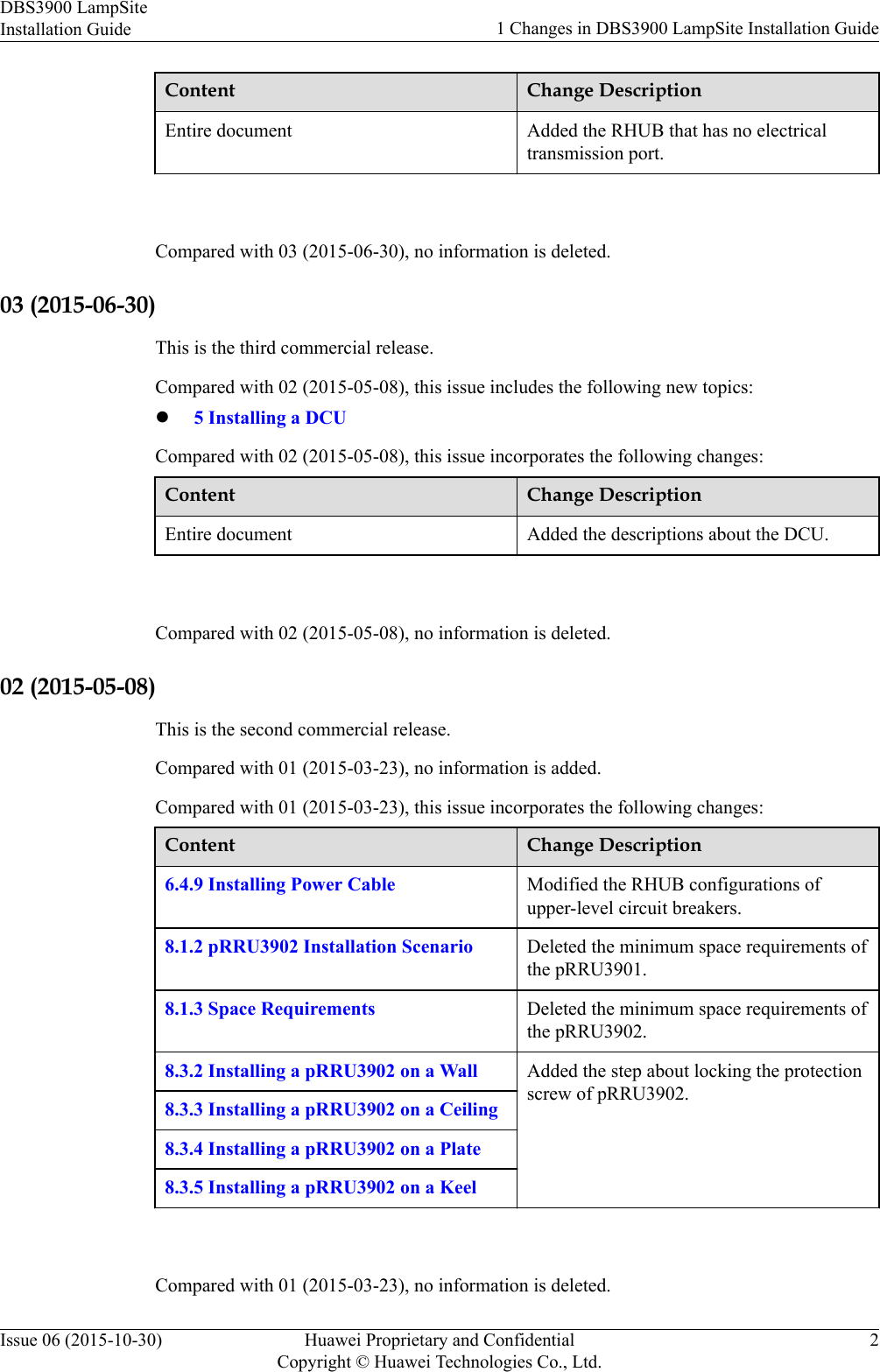
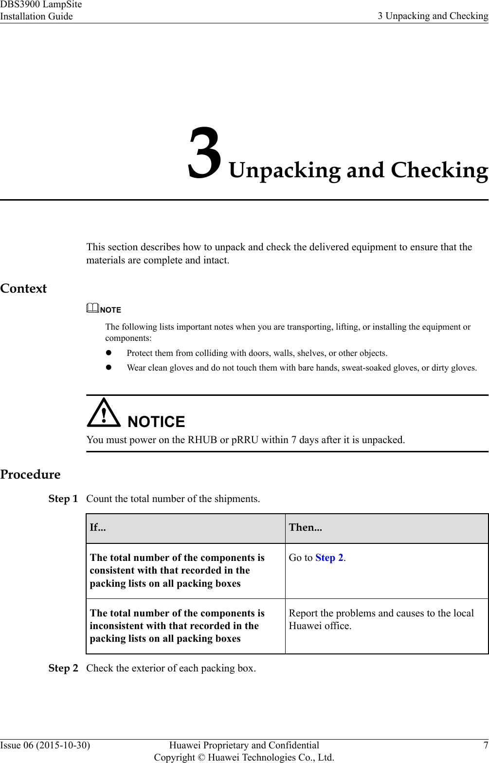
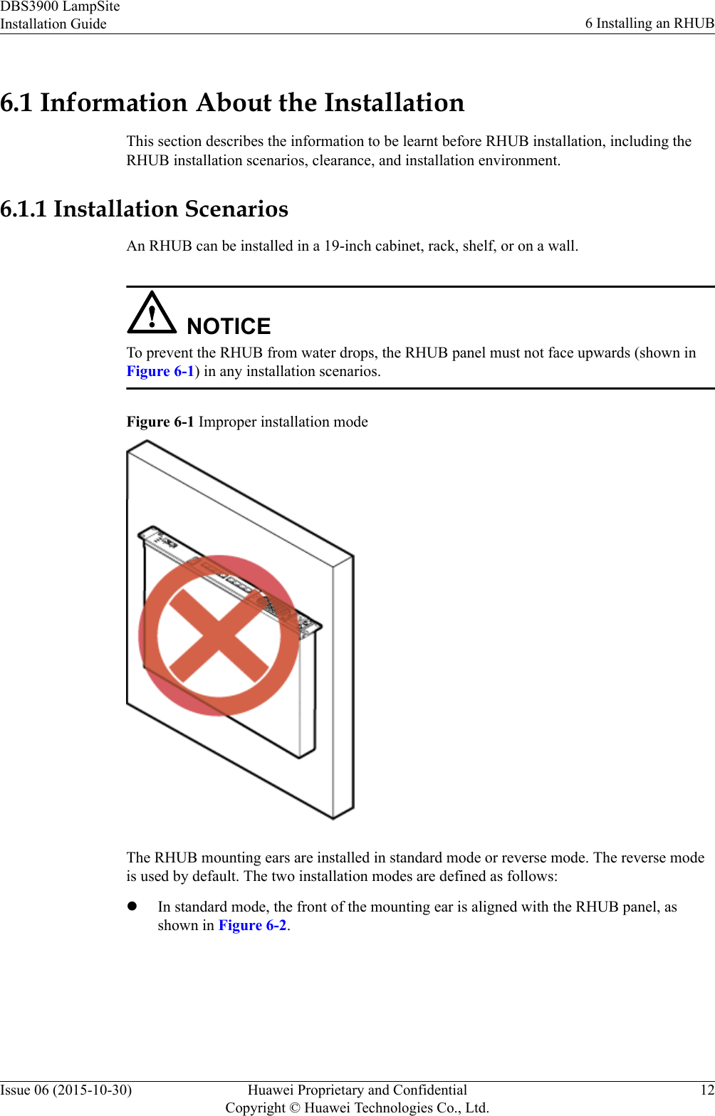
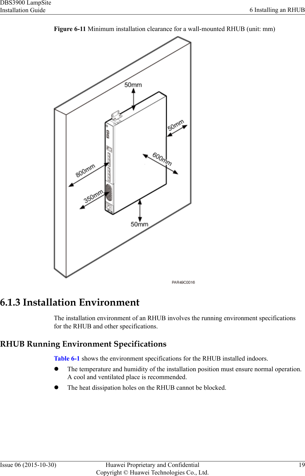
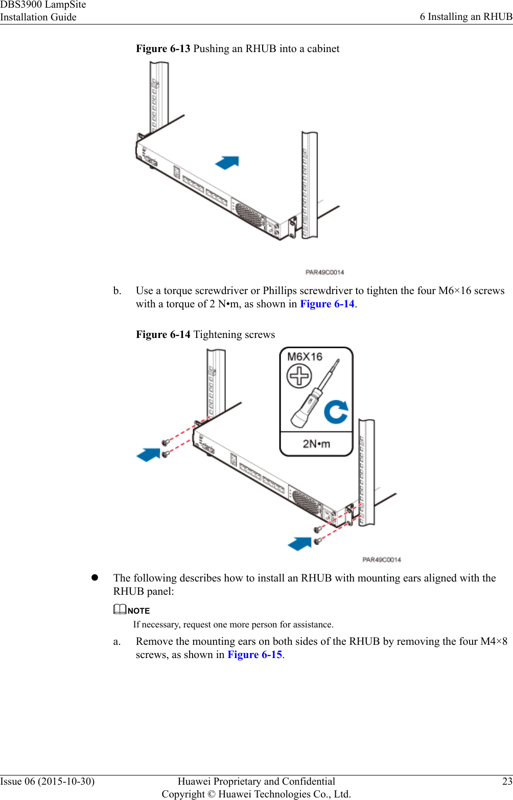
![General Cabling RequirementsBending radius requirementslThe bending radius of a 7/8'' feeder must be greater than 250 mm (9.84 in.), and thebending radius of a 5/4'' feeder must be greater than 380 mm (14.96 in.).lThe bending radius of a 1/4'' jumper must be greater than 35 mm (1.38 in.). The bendingradius of a super-flexible 1/2'' jumper must be greater than 50 mm (1.97 in.), and thebending radius of an ordinary 1/2'' jumper must be greater than 127 mm (5.00 in.).lThe bending radius of a PGND cable must be at least three times its diameter.lThe bending radius of a signal cable must be at least five times its diameter.Cable binding requirementslCables of the same type must be bound together.lDifferent types of cables must be separately laid out and bound, with a minimumdistance of 30 mm (1.18 in.) from each other.lCables must be bound tightly and neatly. The sheaths of cables must not be damaged.lCable ties must face the same direction, and those at the same horizontal line must be ina straight line.lThe excess of indoor cable ties must be cut off. The excess of 5 mm (0.197 in.) ofoutdoor cable ties should be reserved, and the cut surfaces must be smooth without sharpedges.lAfter cables are installed, labels or nameplates must be attached to the cables at theirends, curves, and interconnection positions.Security requirementslWhen laying out cables, avoid sharp objects, for example sharp edges on the wall. Ifnecessary, use tubes to protect the cables.lWhen laying out cables, keep cables away from heat sources, or use heat insulationmaterials to insulate the cables from the heat sources.lReserve a proper distance (0.1 m [3.937 in.] is recommended) between equipment andcables especially at the cable curves to protect the cables and equipment.Indoor cabling requirementslRoute each cable into the room through the feeder window.lReserve drip loops for all cables outside the feeder window before routing them into theroom. Ensure that the radiuses of the drip loops are greater than or equal to the minimumbending radiuses of the cables.lWhen routing a cable into the room, ensure that a person is assisting you in the room.lApply waterproof treatment to the feeder window.Outdoor Cabling RequirementslProtect outdoor cables against potential damage. For example, thread the cables throughtubes.lCables to be protected include AC power cables, transmission cables, and cables laid outunderground.lUse cable clips to secure cables outdoors.lArrange cables neatly along the routing direction and use cable clips to secure the cables.DBS3900 LampSiteInstallation Guide 9 Installing a pRRU3907Issue 06 (2015-10-30) Huawei Proprietary and ConfidentialCopyright © Huawei Technologies Co., Ltd.149](https://usermanual.wiki/Huawei-Technologies/PRRU3901B2B5/User-Guide-2847188-Page-155.png)