Huawei Technologies PRRU3911 pico Remote Radio Unit User Manual Installation Guide
Huawei Technologies Co.,Ltd pico Remote Radio Unit Installation Guide
Users Manual

DBS3900 LampSite
Installation Guide
Issue 07
Date 2015-12-30
HUAWEI TECHNOLOGIES CO., LTD.

Copyright © Huawei Technologies Co., Ltd. 2015. All rights reserved.
No part of this document may be reproduced or transmitted in any form or by any means without prior written
consent of Huawei Technologies Co., Ltd.
Trademarks and Permissions
and other Huawei trademarks are trademarks of Huawei Technologies Co., Ltd.
All other trademarks and trade names mentioned in this document are the property of their respective
holders.
Notice
The purchased products, services and features are stipulated by the contract made between Huawei and the
customer. All or part of the products, services and features described in this document may not be within the
purchase scope or the usage scope. Unless otherwise specified in the contract, all statements, information,
and recommendations in this document are provided "AS IS" without warranties, guarantees or
representations of any kind, either express or implied.
The information in this document is subject to change without notice. Every effort has been made in the
preparation of this document to ensure accuracy of the contents, but all statements, information, and
recommendations in this document do not constitute a warranty of any kind, express or implied.
Huawei Technologies Co., Ltd.
Address: Huawei Industrial Base
Bantian, Longgang
Shenzhen 518129
People's Republic of China
Website: http://www.huawei.com
Email: support@huawei.com
Issue 07 (2015-12-30) Huawei Proprietary and Confidential
Copyright © Huawei Technologies Co., Ltd.
i
About This Document
Overview
This document describes how to install the modules and cables for the BBU, DCU3900,
RHUB3908, pRRU3901, pRRU3902, pRRU3907, and pRRU3911. It also provides checklists
for hardware installation.
NOTE
lUnless otherwise specified, BBU in this document refers to BBU3900 and BBU3910.
lDCU3900 in this document refers to DCU.
lRHUB3908 in this document refers to RHUB.
lUnless otherwise specified, pRRU in this document refers to pRRU3901, pRRU3902, pRRU3907, and
pRRU3911.
Product Version
The following table lists the product version related to this document.
Product Name Solution Version Product Version
DBS3900 LampSite lSRAN10.1 and later versions
lRAN17.1 and later versions
leRAN8.1 and later versions
leRAN TDD 8.1 and later
versions
V100R010C10 and later
versions
Intended Audience
This document is intended for:
lBTS installation personnel
DBS3900 LampSite
Installation Guide About This Document
Issue 07 (2015-12-30) Huawei Proprietary and Confidential
Copyright © Huawei Technologies Co., Ltd.
ii

Contents
About This Document.....................................................................................................................ii
1 Changes in DBS3900 LampSite Installation Guide................................................................1
2 Installation Preparations..............................................................................................................5
2.1 Reference Documents.....................................................................................................................................................6
2.2 Preparing Tools and Instruments.................................................................................................................................... 6
2.3 Requirements for Installation Personnel.........................................................................................................................7
3 Unpacking and Checking............................................................................................................ 8
4 Installing a BBU...........................................................................................................................10
5 Installing a DCU.......................................................................................................................... 11
6 Installing an RHUB.....................................................................................................................12
6.1 Information About the Installation............................................................................................................................... 13
6.1.1 Installation Scenarios.................................................................................................................................................13
6.1.2 Installation Clearance Requirements......................................................................................................................... 18
6.1.3 Installation Environment........................................................................................................................................... 20
6.2 Installation Process....................................................................................................................................................... 22
6.3 Installing an RHUB...................................................................................................................................................... 23
6.3.1 Installing an RHUB in a 19-Inch Cabinet or Rack....................................................................................................23
6.3.2 Installing an RHUB in a 19-Inch Shelf..................................................................................................................... 26
6.3.3 Installing an RHUB on a Wall...................................................................................................................................29
6.4 Installing RHUB Cables............................................................................................................................................... 33
6.4.1 Requirements for Cable Layout.................................................................................................................................33
6.4.2 Cable List...................................................................................................................................................................36
6.4.3 Cable Connections.....................................................................................................................................................38
6.4.4 Cable Installation Process..........................................................................................................................................39
6.4.5 Installing PGND Cable..............................................................................................................................................40
6.4.6 Installing Ethernet Cable........................................................................................................................................... 42
6.4.7 Installing CRPI Optical Cables..................................................................................................................................45
6.4.8 Installing Alarm Cable (Optional).............................................................................................................................47
6.4.9 Installing Power Cable...............................................................................................................................................48
6.5 Checking the RHUB Hardware Installation................................................................................................................. 49
6.6 Power-on Check on an RHUB......................................................................................................................................51
DBS3900 LampSite
Installation Guide Contents
Issue 07 (2015-12-30) Huawei Proprietary and Confidential
Copyright © Huawei Technologies Co., Ltd.
iii

7 Installing a pRRU3901................................................................................................................ 53
7.1 Information About the Installation............................................................................................................................... 54
7.1.1 Product Family.......................................................................................................................................................... 54
7.1.2 Installation Scenario.................................................................................................................................................. 55
7.1.3 Space Requirements.................................................................................................................................................. 59
7.1.4 Installation Environment Requirements.................................................................................................................... 60
7.2 Obtaining the MAC Address (Optional) ..................................................................................................................... 61
7.3 Installation Process....................................................................................................................................................... 61
7.4 Installing a pRRU3901................................................................................................................................................. 62
7.4.1 pRRU3901 Mounting Kits.........................................................................................................................................63
7.4.2 Installing a pRRU3901 on a Wall..............................................................................................................................64
7.4.3 Installing a pRRU3901 on a Ceiling..........................................................................................................................67
7.4.4 Installing a pRRU3901 on a Pole.............................................................................................................................. 70
7.4.5 Installing a pRRU3901 on a Plate............................................................................................................................. 72
7.4.6 Installing a pRRU3901 on a Keel..............................................................................................................................75
7.4.7 Installing the Cabinet.................................................................................................................................................78
7.5 Installing pRRU3901 Cables........................................................................................................................................ 85
7.5.1 Requirements for Cable Layout.................................................................................................................................85
7.5.2 pRRU3901 Cable List............................................................................................................................................... 87
7.5.3 Cable Connections (Indoor).......................................................................................................................................88
7.5.4 Cable Connections (Outdoor)....................................................................................................................................91
7.5.5 Cable Connections (LTE TDD)................................................................................................................................. 92
7.5.6 pRRU3901 cable installation process........................................................................................................................94
7.5.7 Installing an Ethernet Cable...................................................................................................................................... 94
7.5.8 Installing an RF jumpers (Optional)..........................................................................................................................96
7.6 Checking the pRRU3901 Hardware Installation.......................................................................................................... 98
7.7 Powering on the pRRU3901.......................................................................................................................................100
8 Installing a pRRU3902 or pRRU3911.....................................................................................101
8.1 Information About the Installation............................................................................................................................. 102
8.1.1 Product Family........................................................................................................................................................ 102
8.1.2 Installation Scenario................................................................................................................................................ 104
8.1.3 Space Requirements................................................................................................................................................ 108
8.1.4 Installation Environment Requirements.................................................................................................................. 109
8.2 Installation Process..................................................................................................................................................... 110
8.3 Installing a pRRU3902 or pRRU3911........................................................................................................................ 110
8.3.1 Mounting Kits.......................................................................................................................................................... 111
8.3.2 Installing a pRRU3902 or pRRU3911 on a Wall.....................................................................................................112
8.3.3 Installing a pRRU3902 or pRRU3911 on a Ceiling................................................................................................ 115
8.3.4 Installing a pRRU3902 or pRRU3911 on a Plate.................................................................................................... 119
8.3.5 Installing a pRRU3902 or pRRU3911 on a Keel.................................................................................................... 126
8.3.6 Installing a pRRU3902 or pRRU3911 on Steel Hangers........................................................................................ 129
8.3.7 Installing the Cabinet...............................................................................................................................................133
DBS3900 LampSite
Installation Guide Contents
Issue 07 (2015-12-30) Huawei Proprietary and Confidential
Copyright © Huawei Technologies Co., Ltd.
iv

8.4 Installing pRRU3902 or pRRU3911 Cables...............................................................................................................137
8.4.1 Requirements for Cable Layout...............................................................................................................................137
8.4.2 Cable List.................................................................................................................................................................138
8.4.3 Cable Connections...................................................................................................................................................140
8.4.4 Cable Installation Process........................................................................................................................................144
8.4.5 Installing a pRRU3902 Ethernet Cable................................................................................................................... 144
8.4.6 Installing a pRRU3911 Ethernet Cable................................................................................................................... 146
8.4.7 Installing a pRRU3902 RF Jumper (Optional)........................................................................................................148
8.4.8 Installing a pRRU3911 RF Jumper (Optional)........................................................................................................ 150
8.5 (Optional) Installing a Combiner................................................................................................................................152
8.6 Checking the pRRU Hardware Installation................................................................................................................ 154
8.7 Powering on the pRRU...............................................................................................................................................155
9 Installing a pRRU3907.............................................................................................................. 157
9.1 Information About the Installation............................................................................................................................. 158
9.1.1 pRRU3907 Product Family..................................................................................................................................... 158
9.1.2 Constraints and Limitations.....................................................................................................................................158
9.1.3 Installation Clearance and Space Requirements......................................................................................................161
9.1.4 Installation Environment Requirements.................................................................................................................. 163
9.2 Installation Process..................................................................................................................................................... 164
9.3 Installing a pRRU3907............................................................................................................................................... 164
9.3.1 pRRU3907 Mounting Kits.......................................................................................................................................165
9.3.2 Installing a pRRU3907 on a Wall............................................................................................................................166
9.3.3 Installing a pRRU3907 on a Pole............................................................................................................................ 170
9.4 Installing pRRU3907 Cables...................................................................................................................................... 172
9.4.1 Cabling Requirements............................................................................................................................................. 172
9.4.2 pRRU3907 Cable List............................................................................................................................................. 174
9.4.3 pRRU3907 Cable Connections................................................................................................................................175
9.4.4 pRRU3907 cable installation process......................................................................................................................175
9.4.5 Installing a PGND Cable......................................................................................................................................... 176
9.4.6 Installing an RF Jumper...........................................................................................................................................177
9.4.7 Opening the Cover Plate of a pRRU3907 Cabling Cavity...................................................................................... 181
9.4.8 Installing an Ethernet Cable.................................................................................................................................... 182
9.4.9 Closing the Cover Plate of a pRRU3907 Cabling Cavity....................................................................................... 184
9.5 Checking the pRRU3907 Hardware Installation........................................................................................................ 185
9.6 Powering on the pRRU3907.......................................................................................................................................187
10 (Optional) Installing the PoE Surge Protector and Cables..............................................189
11 (Optional) Installing the RF Surge Protector and Cables................................................191
12 (Optional) Installing the Extender....................................................................................... 193
13 (Optional) Installing the Cabinet and Cabinet Cables.................................................... 197
13.1 Installation Clearance Requirements........................................................................................................................ 198
DBS3900 LampSite
Installation Guide Contents
Issue 07 (2015-12-30) Huawei Proprietary and Confidential
Copyright © Huawei Technologies Co., Ltd.
v

13.2 Mounting Bracket and Attachment Plate..................................................................................................................198
13.2.1 Mounting Bracket.................................................................................................................................................. 198
13.2.2 Attachment Plate....................................................................................................................................................199
13.3 Installing a Cabinet...................................................................................................................................................200
13.3.1 Installing the Cabinet on a Wall.............................................................................................................................200
13.3.2 Installing the Cabinet on a Pole.............................................................................................................................205
13.3.3 Installing the Cabinet on U-steel........................................................................................................................... 207
13.3.4 Installing the Cabinet on Angle Steel.................................................................................................................... 211
13.3.5 Installing the Cabinet on Metal Grid..................................................................................................................... 214
13.3.6 Installing the Cabinet on the Floor........................................................................................................................ 219
13.4 Installing Cabinet Cables..........................................................................................................................................223
13.4.1 Cable Connections.................................................................................................................................................223
13.4.2 Installing a PGND Cable for the Cabinet.............................................................................................................. 226
14 Appendix...................................................................................................................................228
14.1 MAC Collection Template........................................................................................................................................229
14.2 Assembling a Shielded RJ45 Connector and an Ethernet Cable.............................................................................. 229
14.3 DBS3900 LampSite Engineering Label................................................................................................................... 233
14.4 Attaching an L-Shaped Label................................................................................................................................... 236
14.5 Attaching a Sign Plate Label.................................................................................................................................... 237
Index................................................................................................................................................240
DBS3900 LampSite
Installation Guide Contents
Issue 07 (2015-12-30) Huawei Proprietary and Confidential
Copyright © Huawei Technologies Co., Ltd.
vi
1 Changes in DBS3900 LampSite Installation
Guide
This chapter describes the changes in the DBS3900 LampSite Installation Guide.
07 (2015-12-30)
This is the seventh commercial release.
Compared with 06 (2015-10-30), this issue incorporates the following new topics:
l8.4.6 Installing a pRRU3911 Ethernet Cable
l10 (Optional) Installing the PoE Surge Protector and Cables
l11 (Optional) Installing the RF Surge Protector and Cables
l13 (Optional) Installing the Cabinet and Cabinet Cables
Compared with 06 (2015-10-30), this issue incorporates the following changes:
Content Change Description
Entire document Added the information about pRRU3911
and the cabinet used in the outside scenario.
Compared with 06 (2015-10-30), no information is deleted.
06 (2015-10-30)
This is the sixth commercial release.
Compared with 05 (2015-08-30), this issue includes the following new topics:
l9 Installing a pRRU3907
Compared with 05 (2015-08-30), no information is changed.
Compared with 05 (2015-08-30), no information is deleted.
DBS3900 LampSite
Installation Guide 1 Changes in DBS3900 LampSite Installation Guide
Issue 07 (2015-12-30) Huawei Proprietary and Confidential
Copyright © Huawei Technologies Co., Ltd.
1
05 (2015-08-30)
This is the fifth commercial release.
Compared with 04 (2015-07-30), no information is added.
Compared with 04 (2015-07-30), this issue incorporates the following changes
Content Change Description
6.4.7 Installing CRPI Optical Cables Added the descriptions about the CPRI
optical fiber connection in sharing BBUs
with Macro Networks scenario.
Compared with 04 (2015-07-30), no information is deleted.
04 (2015-07-30)
This is the fourth commercial release.
Compared with 03 (2015-06-30), no information is added.
Compared with 03 (2015-06-30), this issue incorporates the following changes.
Content Change Description
Entire document Added the RHUB that has no electrical
transmission port.
Compared with 03 (2015-06-30), no information is deleted.
03 (2015-06-30)
This is the third commercial release.
Compared with 02 (2015-05-08), this issue includes the following new topics:
l5 Installing a DCU
Compared with 02 (2015-05-08), this issue incorporates the following changes:
Content Change Description
Entire document Added the descriptions about the DCU.
Compared with 02 (2015-05-08), no information is deleted.
02 (2015-05-08)
This is the second commercial release.
Compared with 01 (2015-03-23), no information is added.
DBS3900 LampSite
Installation Guide 1 Changes in DBS3900 LampSite Installation Guide
Issue 07 (2015-12-30) Huawei Proprietary and Confidential
Copyright © Huawei Technologies Co., Ltd.
2
Compared with 01 (2015-03-23), this issue incorporates the following changes:
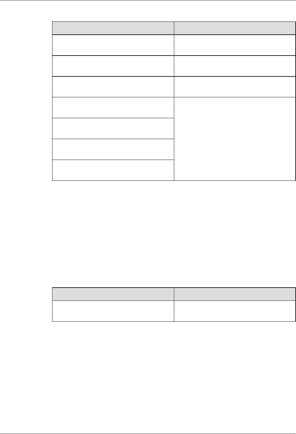
Content Change Description
6.4.9 Installing Power Cable Modified the RHUB configurations of
upper-level circuit breakers.
8.1.2 Installation Scenario Deleted the minimum space requirements of
the pRRU3901.
8.1.3 Space Requirements Deleted the minimum space requirements of
the pRRU3902.
8.3.2 Installing a pRRU3902 or
pRRU3911 on a Wall
Added the step about locking the protection
screw of pRRU3902.
8.3.3 Installing a pRRU3902 or
pRRU3911 on a Ceiling
8.3.4 Installing a pRRU3902 or
pRRU3911 on a Plate
8.3.5 Installing a pRRU3902 or
pRRU3911 on a Keel
Compared with 01 (2015-03-23), no information is deleted.
01 (2015-03-23)
This is the first commercial release.
Compared with draft B (2015-02-10), this issue includes the following new topics:
l8 Installing a pRRU3902 or pRRU3911
Compared with draft B (2015-02-10), this issue incorporates the following changes:
Content Change Description
Entire document Added the descriptions about the
pRRU3902.
Compared with draft B (2015-02-10), no information is deleted.
Draft B (2015-02-10)
This is a draft release.
Compared with draft A (2015-01-15), no information is added.
Compared with draft A (2015-01-15), this issue incorporates the following change:
DBS3900 LampSite
Installation Guide 1 Changes in DBS3900 LampSite Installation Guide
Issue 07 (2015-12-30) Huawei Proprietary and Confidential
Copyright © Huawei Technologies Co., Ltd.
3
Content Change Description
6.1.1 Installation Scenarios Added the descriptions about the RHUB
panel must not face upwards.
Compared with draft A (2015-01-15), no information is deleted.
Draft A (2015-01-15)
This is a draft release.
Compared with Issue 08 (2014-12-30) of V100R009C00, no information is added.
Compared with Issue 08 (2014-12-30) of V100R009C00, this issue incorporates the following
change:
Content Change Description
Entire document The base station in the LampSite solution is
renamed DBS3900 LampSite.
Compared with Issue 08 (2014-12-30) of V100R009C00, no information is deleted.
DBS3900 LampSite
Installation Guide 1 Changes in DBS3900 LampSite Installation Guide
Issue 07 (2015-12-30) Huawei Proprietary and Confidential
Copyright © Huawei Technologies Co., Ltd.
4

2 Installation Preparations
About This Chapter
Before starting the installation, you must obtain the required reference documents, tools, and
instruments, and familiarize yourself with the skills required.
2.1 Reference Documents
Before the installation, you must read the following documents:
2.2 Preparing Tools and Instruments
This section describes the tools and instruments that must be prepared before the installation.
2.3 Requirements for Installation Personnel
This section describes requirements for installation engineers. They must be qualified and
trained, and familiar with correct operation methods and safety precautions before performing
any operations.
DBS3900 LampSite
Installation Guide 2 Installation Preparations
Issue 07 (2015-12-30) Huawei Proprietary and Confidential
Copyright © Huawei Technologies Co., Ltd.
5
2.1 Reference Documents
Before the installation, you must read the following documents:
lDBS3900 LampSite Hardware Description
lInstallation Reference
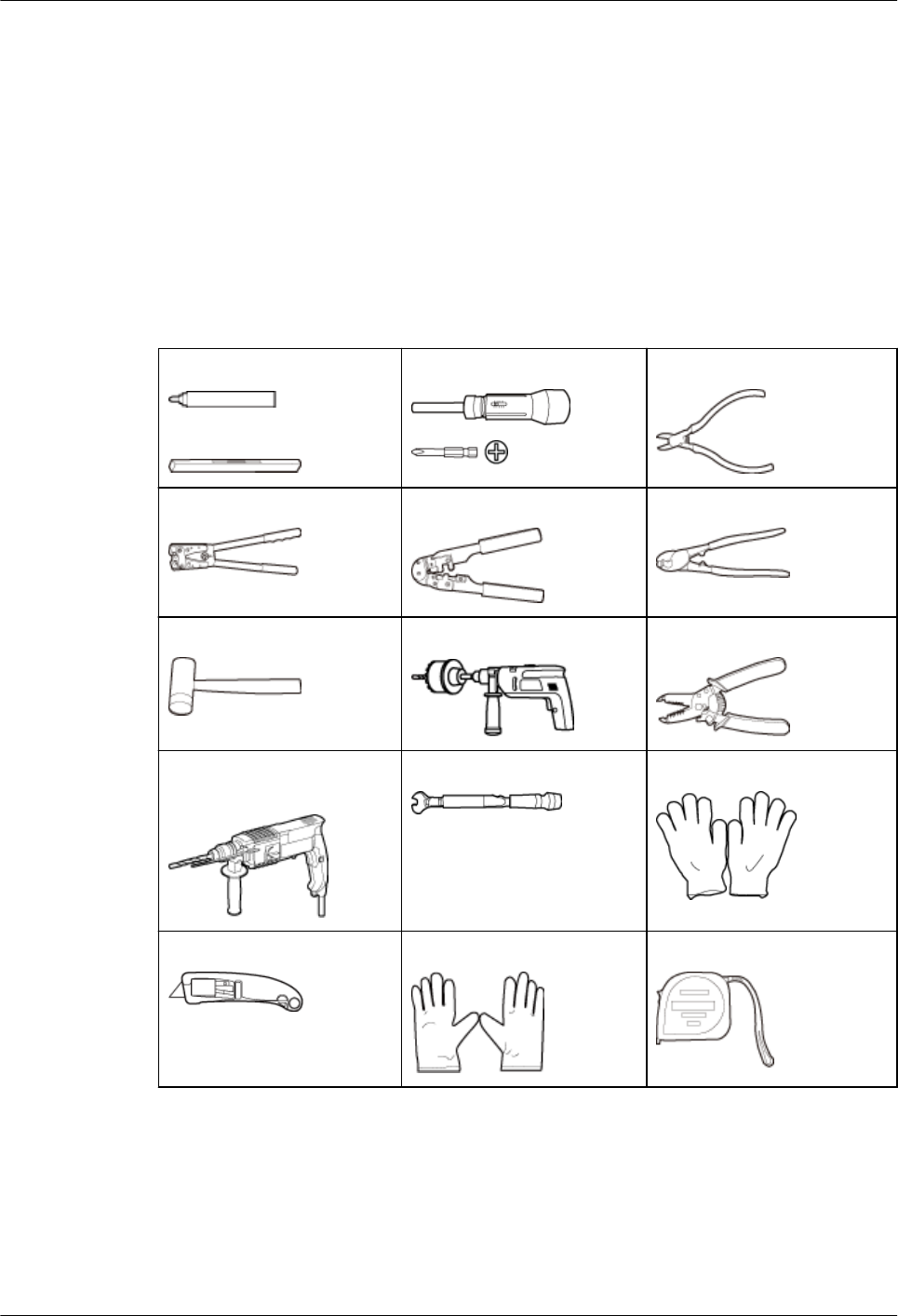
2.2 Preparing Tools and Instruments
This section describes the tools and instruments that must be prepared before the installation.
Marker
Level
Torque screwdriver
(M4 to M6)
Diagonal pliers
Power cable crimping tool RJ11 crimping tool Cable cutter
Rubber mallet Crown saw (Ø60) Wire stripper
Hammer drill (Ø6, Ø8 and
Ø12)
Torque wrench (Ø10 mm) Protective gloves
Guarded blade utility knife ESD gloves Long measuring tape
DBS3900 LampSite
Installation Guide 2 Installation Preparations
Issue 07 (2015-12-30) Huawei Proprietary and Confidential
Copyright © Huawei Technologies Co., Ltd.
6
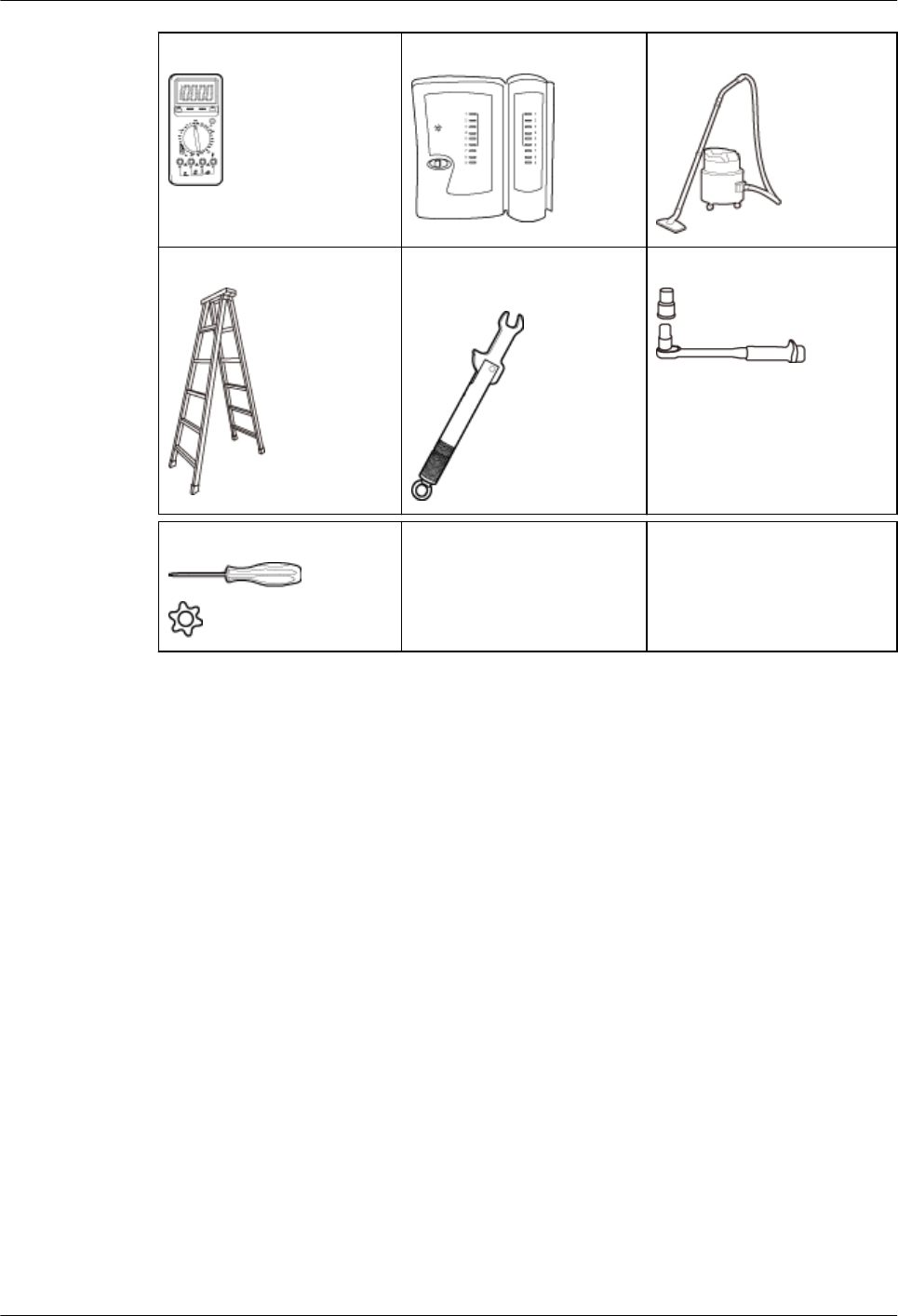
Multimeter Network cable tester Vacuum cleaner
Ladder Torque wrench for SMA
connector
Socket wrench (M6)
Hole screwdriver (T20) –-
2.3 Requirements for Installation Personnel
This section describes requirements for installation engineers. They must be qualified and
trained, and familiar with correct operation methods and safety precautions before performing
any operations.
Before the installation, pay attention to the following items:
lTechnical engineers must take Huawei training and be familiar with proper installation
and operation methods.
lThe number of installation personnel depends on the engineering schedule and
installation environment. Generally, three to five persons are required. Generally, only
three to five onsite personnel are necessary.
DBS3900 LampSite
Installation Guide 2 Installation Preparations
Issue 07 (2015-12-30) Huawei Proprietary and Confidential
Copyright © Huawei Technologies Co., Ltd.
7
3 Unpacking and Checking
This section describes how to unpack and check the delivered equipment to ensure that the
materials are complete and intact.
Context
NOTE
The following lists important notes when you are transporting, lifting, or installing the equipment or
components:
lProtect them from colliding with doors, walls, shelves, or other objects.
lWear clean gloves and do not touch them with bare hands, sweat-soaked gloves, or dirty gloves.
NOTICE
You must power on the RHUB or pRRU within 7 days after it is unpacked.
Procedure
Step 1 Count the total number of the shipments.
If... Then...
The total number of the components is
consistent with that recorded in the
packing lists on all packing boxes
Go to Step 2.
The total number of the components is
inconsistent with that recorded in the
packing lists on all packing boxes
Report the problems and causes to the local
Huawei office.
Step 2 Check the exterior of each packing box.
DBS3900 LampSite
Installation Guide 3 Unpacking and Checking
Issue 07 (2015-12-30) Huawei Proprietary and Confidential
Copyright © Huawei Technologies Co., Ltd.
8
If... Then...
The exterior of each packing box is intact Go to Step 3.
It is damaged or soaked Report the problems and causes to the local
Huawei office.
The collision label is red Do not unpack the packing box and claim for
compensation from the transportation
company.
Step 3 Check the type and quantity of the equipment in the boxes according to the packing list.
If... Then...
The type and number are consistent with
the packing list on each packing list
Sign the Packing List with the operator.
There is any shortage, wrong delivery, or
damaged equipment
Report the problems and causes to the local
Huawei office.
NOTICE
Perform the following operations to protect the components from any damages and help find
out the cause of any damage in future: 1. Store the unpacked equipment and packing materials
indoors. 2. Take photos of the storeroom, rusted or eroded equipment, packing box, and
packing materials. 3. File the photos.
----End
DBS3900 LampSite
Installation Guide 3 Unpacking and Checking
Issue 07 (2015-12-30) Huawei Proprietary and Confidential
Copyright © Huawei Technologies Co., Ltd.
9

4 Installing a BBU
This chapter describes the process of installing a BBU.
For details about the installation of the BBU, see DBS3900 Installation Guide.
DBS3900 LampSite
Installation Guide 4 Installing a BBU
Issue 07 (2015-12-30) Huawei Proprietary and Confidential
Copyright © Huawei Technologies Co., Ltd.
10

5 Installing a DCU
This chapter describes the process of installing a DCU.
For details about the installation of the DCU, see DCU3900 Installation Guide.
DBS3900 LampSite
Installation Guide 5 Installing a DCU
Issue 07 (2015-12-30) Huawei Proprietary and Confidential
Copyright © Huawei Technologies Co., Ltd.
11

6 Installing an RHUB
About This Chapter
This chapter describes the process of installing an RHUB. RHUBs are classified into those
with electrical transmission ports and those with no electrical transmission ports. Unless
otherwise specified, this document uses the RHUBs with no electrical transmission ports as an
example.
6.1 Information About the Installation
This section describes the information to be learnt before RHUB installation, including the
RHUB installation scenarios, clearance, and installation environment.
6.2 Installation Process
The RHUB installation involves installing an RHUB module, installing RHUB cables,
checking the RHUB hardware installation, and powering on the RHUB.
6.3 Installing an RHUB
An RHUB can be installed in a cabinet, rack, shelf, or on a wall.
6.4 Installing RHUB Cables
This section describes how to install cables for an RHUB.
6.5 Checking the RHUB Hardware Installation
After an RHUB is installed, check the installation of hardware including the devices and
related cables.
6.6 Power-on Check on an RHUB
This section describes the power-on check on the RHUB after the RHUB hardware is
installed and checked.
DBS3900 LampSite
Installation Guide 6 Installing an RHUB
Issue 07 (2015-12-30) Huawei Proprietary and Confidential
Copyright © Huawei Technologies Co., Ltd.
12
6.1 Information About the Installation
This section describes the information to be learnt before RHUB installation, including the
RHUB installation scenarios, clearance, and installation environment.
6.1.1 Installation Scenarios
An RHUB can be installed in a 19-inch cabinet, rack, shelf, or on a wall.
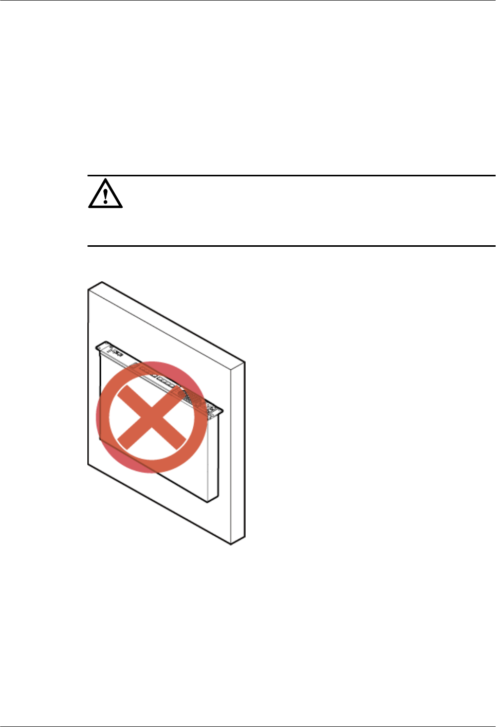
NOTICE
To prevent the RHUB from water drops, the RHUB panel must not face upwards (shown in
Figure 6-1) in any installation scenarios.
Figure 6-1 Improper installation mode
The RHUB mounting ears are installed in standard mode or reverse mode. The reverse mode
is used by default. The two installation modes are defined as follows:
lIn standard mode, the front of the mounting ear is aligned with the RHUB panel, as
shown in Figure 6-2.
DBS3900 LampSite
Installation Guide 6 Installing an RHUB
Issue 07 (2015-12-30) Huawei Proprietary and Confidential
Copyright © Huawei Technologies Co., Ltd.
13
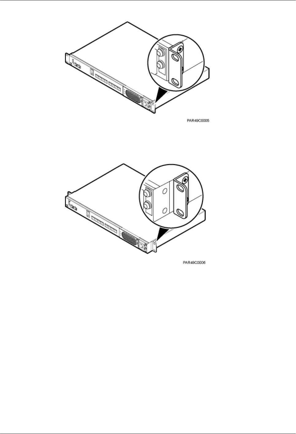
Figure 6-2 Installing mounting ears in standard mode
lIn reverse mode, the front of the mounting ear is 31 mm away from the RHUB panel, as
shown in Figure 6-3.
Figure 6-3 Installing mounting ears in reverse mode
Installing an RHUB in a 19-Inch Cabinet or Rack
Installing an RHUB in a 19-inch cabinet or rack: Secure the mounting ear to the mounting
bracket by using M6 screws.
lIf there are no other modules installed in the 1 U space near the RHUB, install the
RHUB directly. Otherwise, remove the modules before installing the RHUB.
lBefore installation, you need to check the installation mode supported by the rack and
adjust the position of the mounting ear.
Figure 6-4 and Figure 6-5 show RHUBs installed in a cabinet or rack, respectively.
DBS3900 LampSite
Installation Guide 6 Installing an RHUB
Issue 07 (2015-12-30) Huawei Proprietary and Confidential
Copyright © Huawei Technologies Co., Ltd.
14
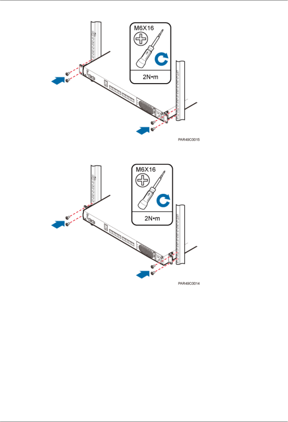
Figure 6-4 Installing an RHUB in a 19-inch cabinet or rack in standard mode
Figure 6-5 Installing an RHUB in a 19-inch cabinet in reverse mode
Installing an RHUB in a 19-Inch Shelf
When an RHUB is installed in a 19-inch shelf, the shelf must be installed on a wall. One shelf
can house multiple RHUBs with 1 U space between two RHUBs.
Figure 6-6 and Figure 6-7 show RHUBs installed in a 19-inch shelf.
DBS3900 LampSite
Installation Guide 6 Installing an RHUB
Issue 07 (2015-12-30) Huawei Proprietary and Confidential
Copyright © Huawei Technologies Co., Ltd.
15
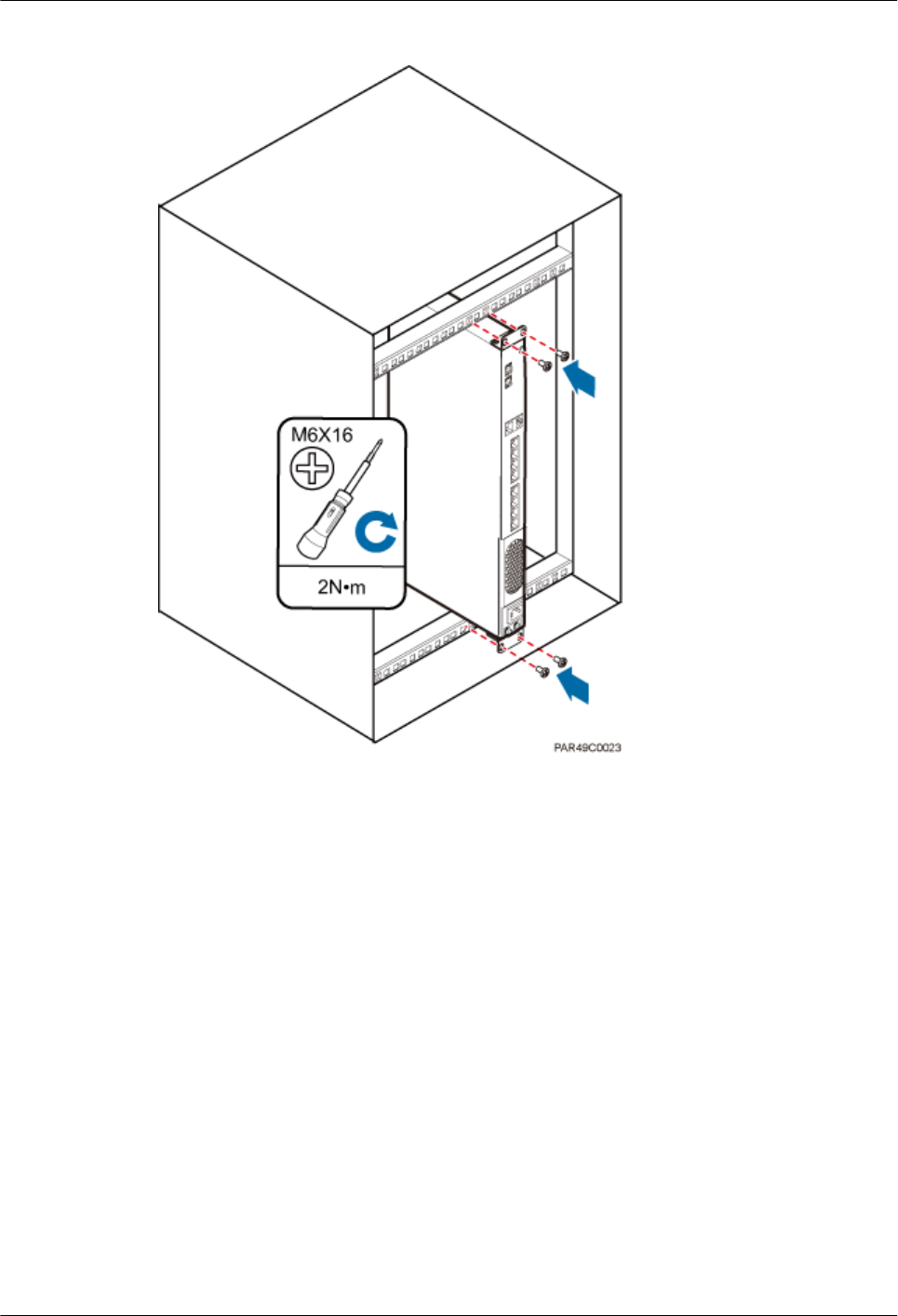
Figure 6-6 RHUB installed in a 19-inch shelf in standard mode
DBS3900 LampSite
Installation Guide 6 Installing an RHUB
Issue 07 (2015-12-30) Huawei Proprietary and Confidential
Copyright © Huawei Technologies Co., Ltd.
16
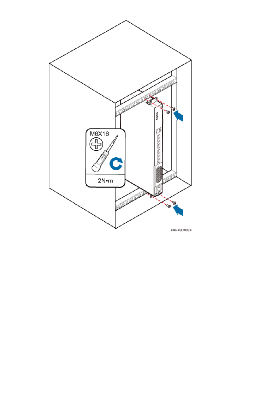
Figure 6-7 RHUB installed in a 19-inch shelf in reverse mode
Installing an RHUB on a Wall
An RHUB can be installed on a wall.
The wall on which an RHUB is installed must meet the following requirements:
lWhen a single RHUB is installed, the wall must have a capacity of bearing at least four
times the weight of the RHUB.
lExpansion bolts must be tightened to 10 N·m (88.507 bf·in.) to ensure the bolts work
properly and the wall remains intact without cracks in it.
Figure 6-8 shows an RHUB installed on a wall.
DBS3900 LampSite
Installation Guide 6 Installing an RHUB
Issue 07 (2015-12-30) Huawei Proprietary and Confidential
Copyright © Huawei Technologies Co., Ltd.
17
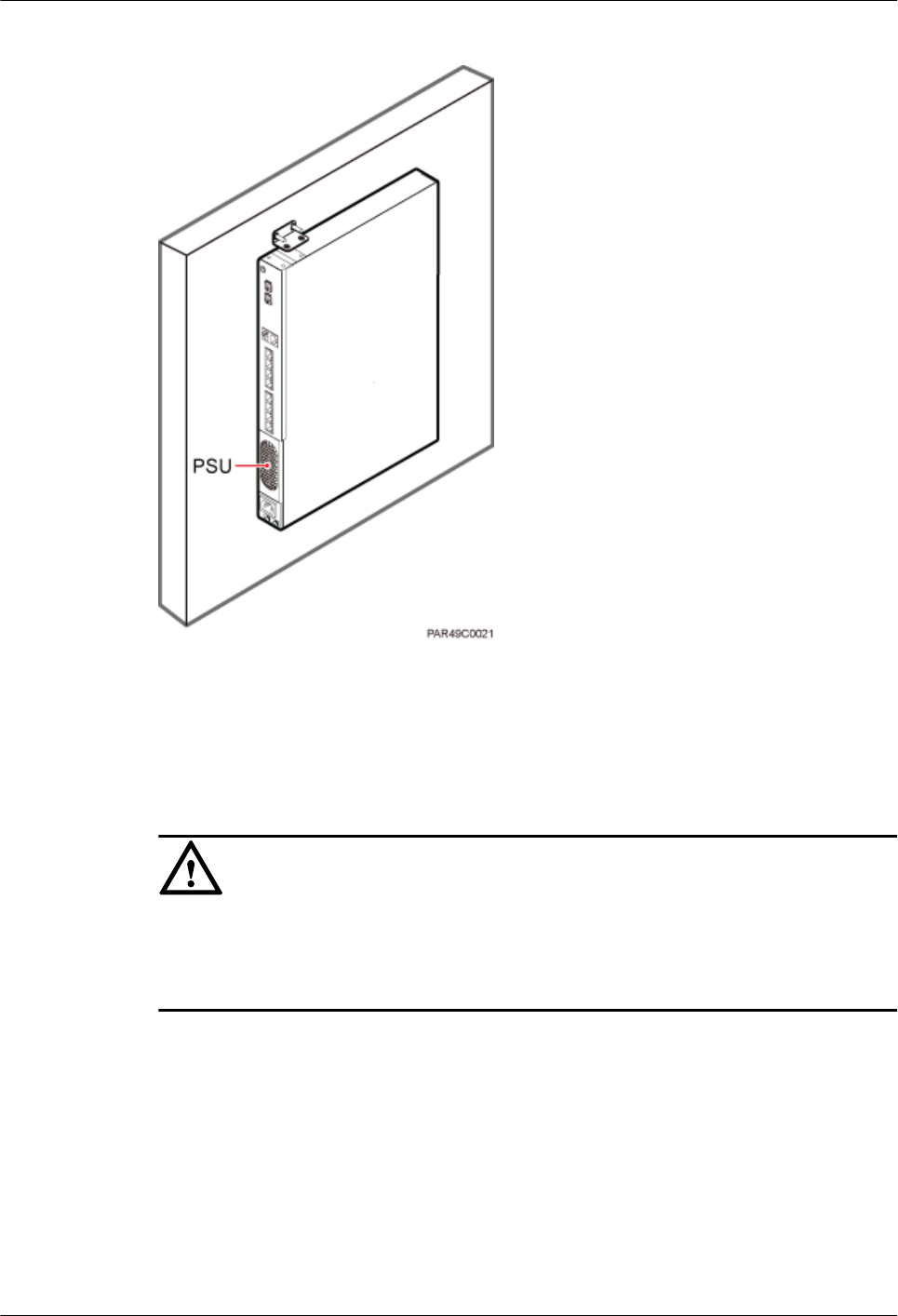
Figure 6-8 RHUB installed on a wall
6.1.2 Installation Clearance Requirements
When an RHUB is installed in a 19-inch cabinet, rack, shelf, or on a wall, a minimum
clearance is required for easy cabling and operation and maintenance. A recommended
installation clearance is provided based on experience.
NOTICE
lDo not install or place inflammable materials above or under an RHUB.
lA clearance of 350 mm must be reserved in front of the air intake vent of the fan of the
power supply unit (PSU) for maintenance.
Figure 6-9 shows the installation clearance for the RHUB installed in a 19-inch cabinet, rack,
or shelf.
DBS3900 LampSite
Installation Guide 6 Installing an RHUB
Issue 07 (2015-12-30) Huawei Proprietary and Confidential
Copyright © Huawei Technologies Co., Ltd.
18
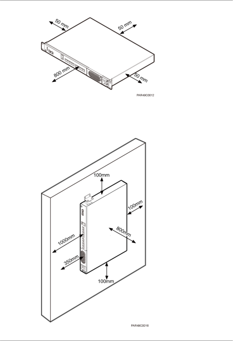
Figure 6-9 Installation clearance for an RHUB installed in a 19-inch cabinet, rack, or shelf
Figure 6-10 and Figure 6-11 shows the recommended and minimum installation clearance
respectively when the RHUB is installed on a wall.
Figure 6-10 Recommended installation clearance for a wall-mounted RHUB (unit: mm)
DBS3900 LampSite
Installation Guide 6 Installing an RHUB
Issue 07 (2015-12-30) Huawei Proprietary and Confidential
Copyright © Huawei Technologies Co., Ltd.
19
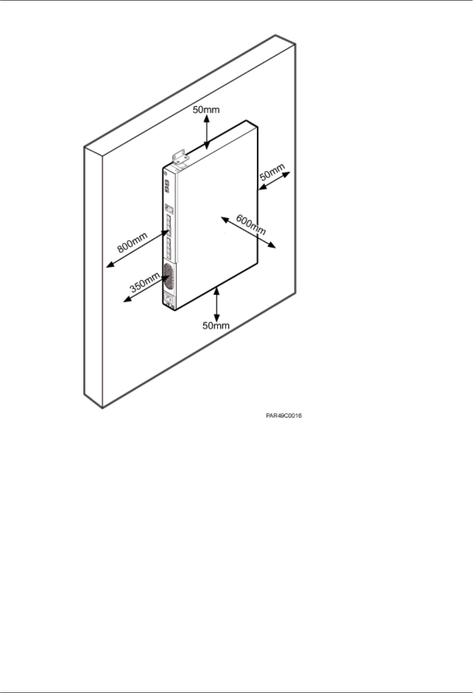
Figure 6-11 Minimum installation clearance for a wall-mounted RHUB (unit: mm)
6.1.3 Installation Environment
The installation environment of an RHUB involves the running environment specifications
for the RHUB and other specifications.
RHUB Running Environment Specifications
Table 6-1 shows the environment specifications for the RHUB installed indoors.
lThe temperature and humidity of the installation position must ensure normal operation.
A cool and ventilated place is recommended.
lThe heat dissipation holes on the RHUB cannot be blocked.
DBS3900 LampSite
Installation Guide 6 Installing an RHUB
Issue 07 (2015-12-30) Huawei Proprietary and Confidential
Copyright © Huawei Technologies Co., Ltd.
20
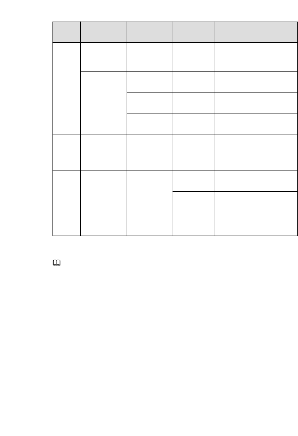
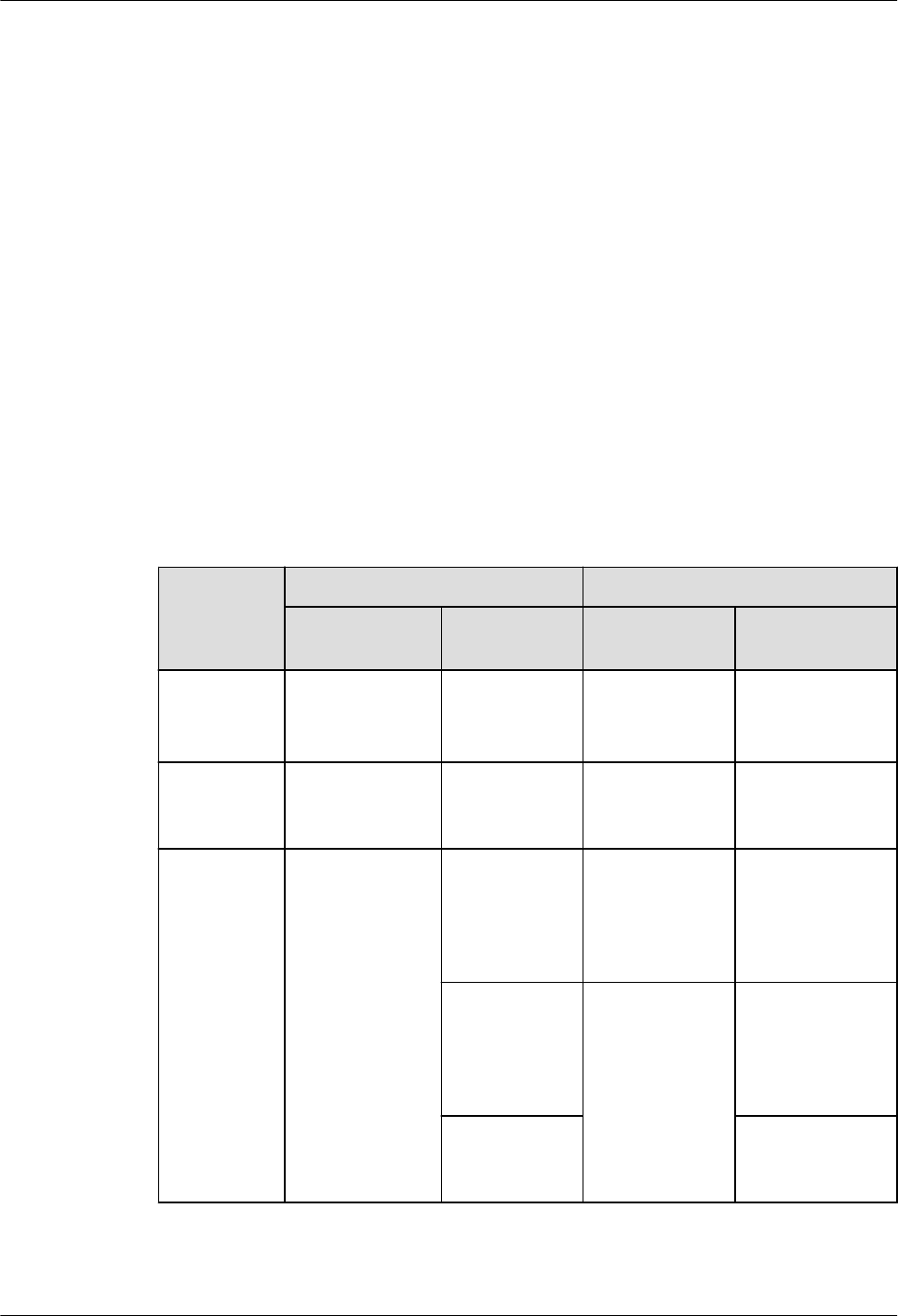
Table 6-1 RHUB environment specifications
Specifi
cations
Installation
Scenario
RHUB
Quantity
Condition Remarks
Operati
ng
tempera
ture
Installed on a
wall or in a 19-
inch rack.
N/A -5°C to
+50°C
N/A
Installed in a
shelf.
1 -5°C to
+45°C
N/A
2 -5°C to
+43°C
N/A
3 -5°C to
+40°C
N/A
Relativ
e
humidit
y
Installed in all
scenarios.
N/A 5% RH to
95% RH
N/A
Altitude N/A N/A -60 m to
+1800 m
Works properly.
1800 m to
4000 m
Above the 1800 m altitude,
the maximum operating
temperature decreases by
1°C each time the altitude
increases by 220 m.
NOTE
Installing more than one RHUB, 1 U space is required between two RHUBs.
Other Running Environment Specifications
lThe RHUB cannot be installed at an air outlet of the heat dissipation box of an air
conditioner or other heat-generating appliances.
lThe RHUB cannot be installed near a strong heat source.
lThe RHUB cannot be installed in a position with water dripping, such as outdoor
equipment of air conditioners, pipe, and leaking or dripping roofs.
lThe installation position must be far from rains. If the RHUB is installed on a wall, there
must be no window on either side of the wall.
lThe installation position must be far away from high voltage, highly corrosive devices,
flammable or explosive substances, and electromagnetic interference such as power
stations, high-voltage substations, and wired TV towers.
lThe RHUB must be installed in a dry, ventilating, and dust-proof place.
lIf the RHUB is installed in parking areas or basements, the installation position must be
well-ventilated.
DBS3900 LampSite
Installation Guide 6 Installing an RHUB
Issue 07 (2015-12-30) Huawei Proprietary and Confidential
Copyright © Huawei Technologies Co., Ltd.
21

Requirements for the Upper-level Circuit Breaker
Type C upper-level AC circuit breakers or slow-blow fuses must be used for power cables.
The maximum current must not exceed 16 A. Table 6-2 describes the recommended
specifications.
Table 6-2 Circuit breaker specifications for power cables
Power Supply Upper-level AC Circuit
Breaker (For a single
RHUB)
Cross-Sectional Area of
the Input Power Cable
220 V AC single-phase ≥ 6 A 1.5 mm2
110 V AC dual-live-wire
110 V AC single-phase ≥ 12 A
6.2 Installation Process
The RHUB installation involves installing an RHUB module, installing RHUB cables,
checking the RHUB hardware installation, and powering on the RHUB.
Figure 6-12 shows the RHUB installation process.
DBS3900 LampSite
Installation Guide 6 Installing an RHUB
Issue 07 (2015-12-30) Huawei Proprietary and Confidential
Copyright © Huawei Technologies Co., Ltd.
22
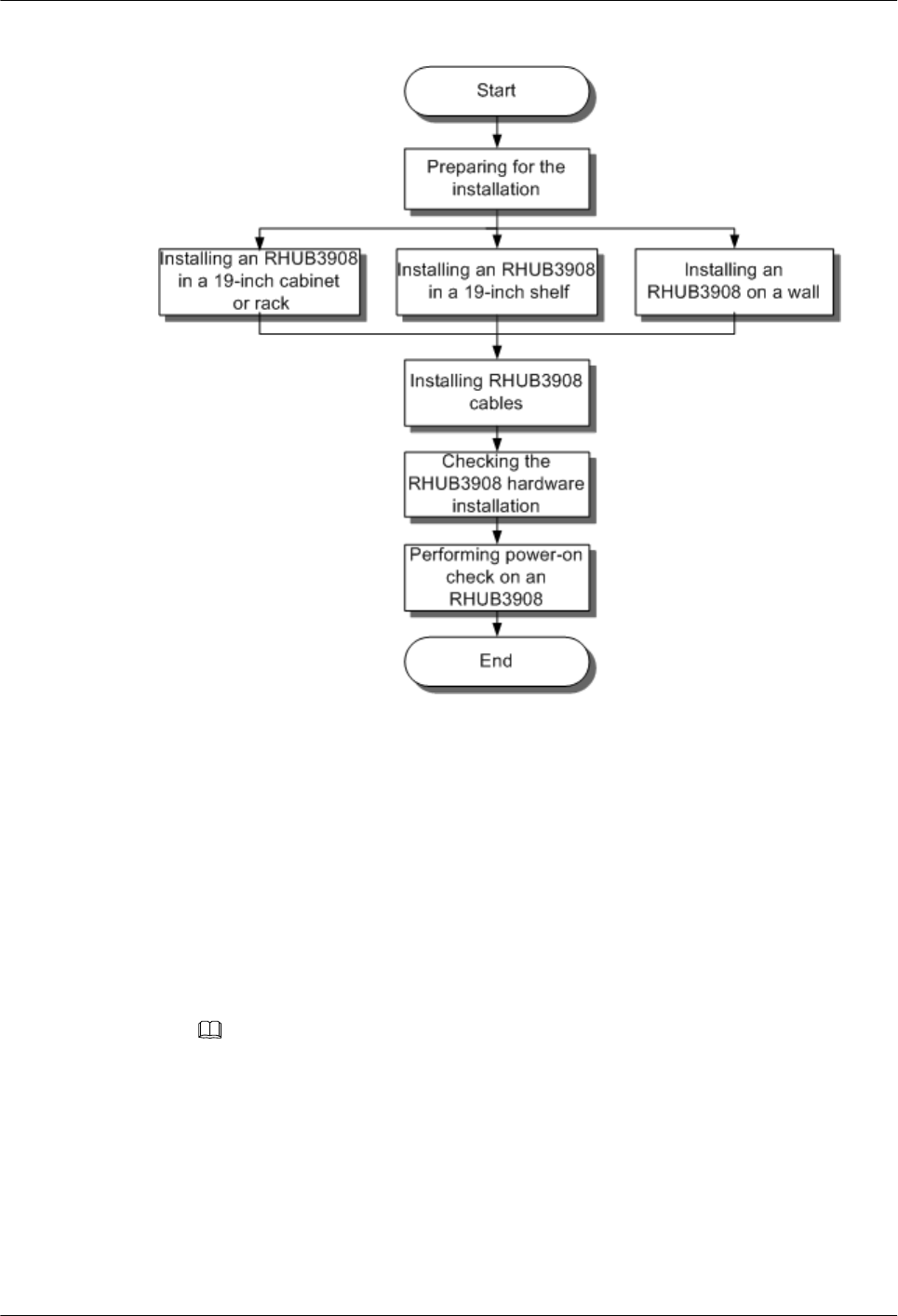
Figure 6-12 RHUB installation process
6.3 Installing an RHUB
An RHUB can be installed in a cabinet, rack, shelf, or on a wall.
6.3.1 Installing an RHUB in a 19-Inch Cabinet or Rack
This section describes how to install an RHUB in a 19-inch cabinet.
Procedure
lThe following describes how to install an RHUB with mounting ears in reverse mode:
NOTE
If necessary, request one more person for assistance.
a. With one hand holding it, align the mounting holes with the installation holes,
slowly push the RHUB into the required position in the cabinet, as shown in Figure
6-13.
DBS3900 LampSite
Installation Guide 6 Installing an RHUB
Issue 07 (2015-12-30) Huawei Proprietary and Confidential
Copyright © Huawei Technologies Co., Ltd.
23
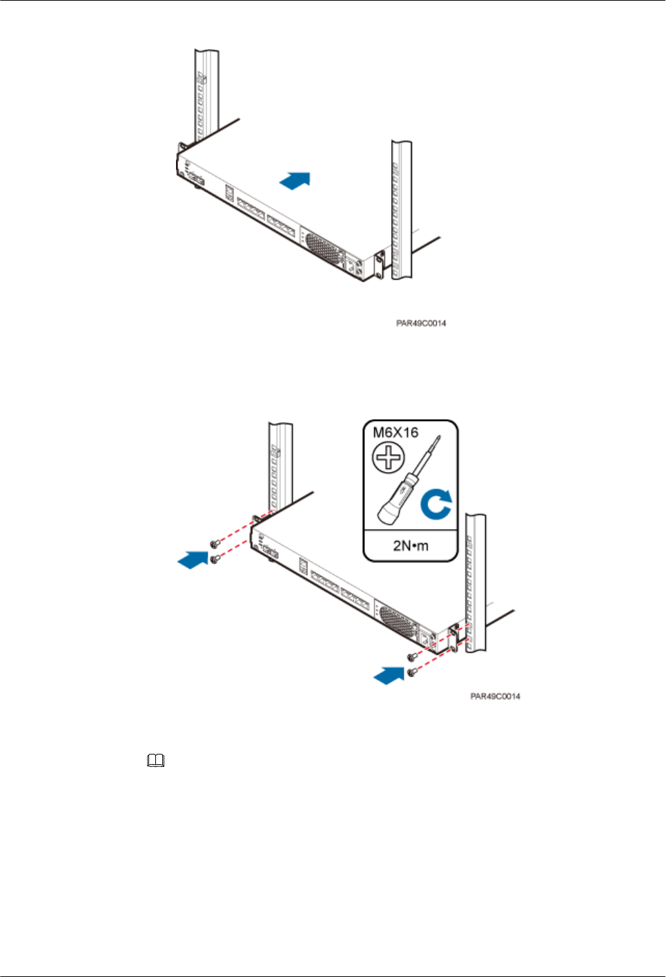
Figure 6-13 Pushing an RHUB into a cabinet
b. Use a torque screwdriver or Phillips screwdriver to tighten the four M6×16 screws
with a torque of 2 N•m, as shown in Figure 6-14.
Figure 6-14 Tightening screws
lThe following describes how to install an RHUB with mounting ears aligned with the
RHUB panel:
NOTE
If necessary, request one more person for assistance.
a. Remove the mounting ears on both sides of the RHUB by removing the four M4×8
screws, as shown in Figure 6-15.
DBS3900 LampSite
Installation Guide 6 Installing an RHUB
Issue 07 (2015-12-30) Huawei Proprietary and Confidential
Copyright © Huawei Technologies Co., Ltd.
24
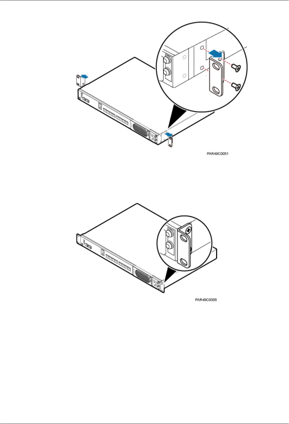
Figure 6-15 Removing mounting ears and screws
b. Use a torque screwdriver or Phillips screwdriver to tighten the four M4×8 screws
with a torque of 1.4 N•m to install the removed mounting ears again, as shown in
Figure 6-16. The mounting ears must be aligned with the RHUB panel.
Figure 6-16 Installing mounting ears in standard mode
c. With one hand holding it, align the mounting holes with the installation holes,
slowly push the RHUB into the required position in the cabinet, as shown in Figure
6-17.
DBS3900 LampSite
Installation Guide 6 Installing an RHUB
Issue 07 (2015-12-30) Huawei Proprietary and Confidential
Copyright © Huawei Technologies Co., Ltd.
25
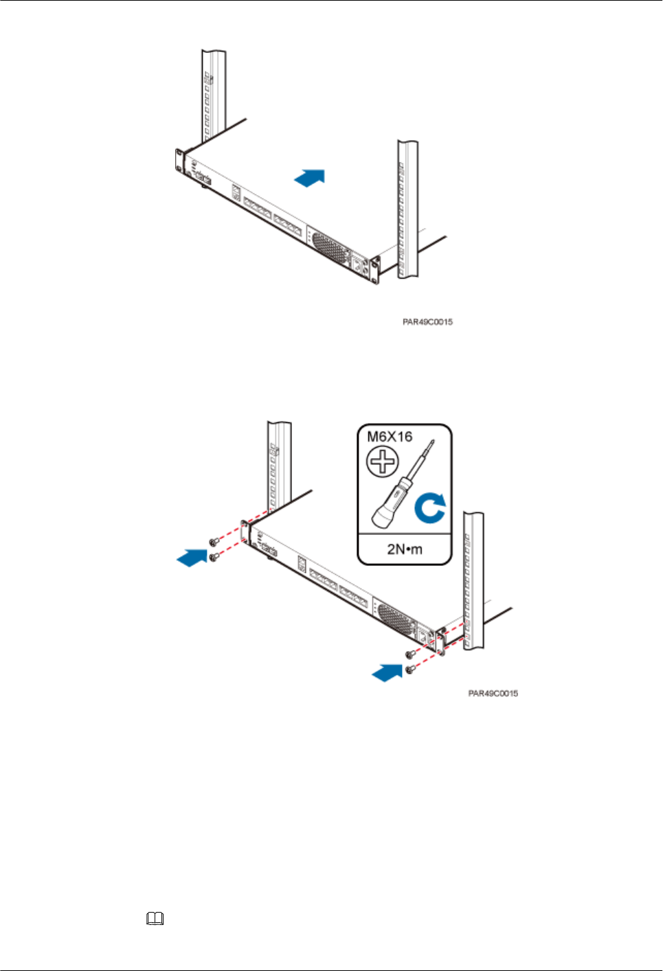
Figure 6-17 Pushing an RHUB into a cabinet
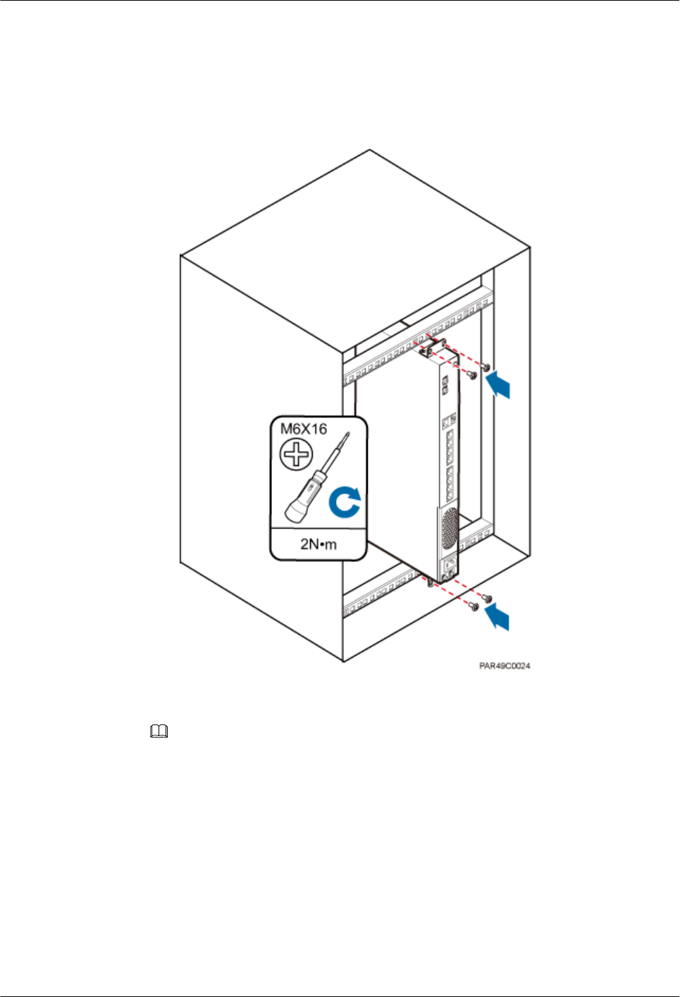
d. Use a torque screwdriver or Phillips screwdriver to tighten the four M6×16 screws
with a torque of 2 N•m, as shown in Figure 6-18.
Figure 6-18 Tightening screws
----End
6.3.2 Installing an RHUB in a 19-Inch Shelf
If a shelf houses more than one RHUB, 1 U space is required between two RHUBs. The PSU
must be installed at the bottom of the cabinet.
Procedure
lThe following describes how to install an RHUB with mounting ears installed in reverse
mode:
NOTE
If necessary, request one more person for assistance.
DBS3900 LampSite
Installation Guide 6 Installing an RHUB
Issue 07 (2015-12-30) Huawei Proprietary and Confidential
Copyright © Huawei Technologies Co., Ltd.
26
a. With one hand holding it, align the mounting holes with the installation holes,
slowly push the RHUB into the required position in the shelf.
b. Use a torque screwdriver or Phillips screwdriver to tighten the four M6×16 screws
with a torque of 2 N•m, as shown in Figure 6-19.
Figure 6-19 Tightening screws
lThe following describes how to install an RHUB with mounting ears installed in
standard mode:
NOTE
If necessary, request one more person for assistance.
a. Remove the mounting ears on both sides of the RHUB by removing the four M4×8
screws, as shown in Figure 6-20.
DBS3900 LampSite
Installation Guide 6 Installing an RHUB
Issue 07 (2015-12-30) Huawei Proprietary and Confidential
Copyright © Huawei Technologies Co., Ltd.
27

Figure 6-20 Removing mounting ears and screws
b. Use a torque screwdriver or Phillips screwdriver to tighten the four M4×8 screws
with a torque of 1.4 N•m to install the removed mounting ears again, as shown in
Figure 6-21. The mounting ears must be aligned with the RHUB panel.
Figure 6-21 Installing mounting ears in standard mode
c. With one hand holding it, align the mounting holes with the installation holes,
slowly push the RHUB into the required position in the cabinet, as shown in .
d. Use a torque screwdriver or Phillips screwdriver to tighten the four M6×16 screws
with a torque of 2 N•m, as shown in Figure 6-22.
DBS3900 LampSite
Installation Guide 6 Installing an RHUB
Issue 07 (2015-12-30) Huawei Proprietary and Confidential
Copyright © Huawei Technologies Co., Ltd.
28
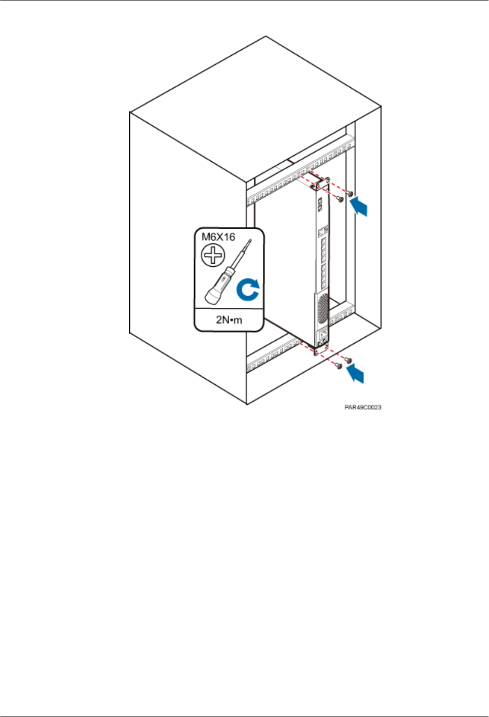
Figure 6-22 Tightening screws
----End
6.3.3 Installing an RHUB on a Wall
An RHUB can be installed on a wall.
Procedure
Step 1 The mounting ears are installed in reverse mode by default. Before installing an RHUB on a
wall, modify the installation mode of the mounting ears on the RHUB.
lUse a torque screwdriver or Phillips screwdriver to remove the mounting ears on both
sides of the RHUB by removing the four M4×8 screws, as shown in Figure 6-23.
DBS3900 LampSite
Installation Guide 6 Installing an RHUB
Issue 07 (2015-12-30) Huawei Proprietary and Confidential
Copyright © Huawei Technologies Co., Ltd.
29
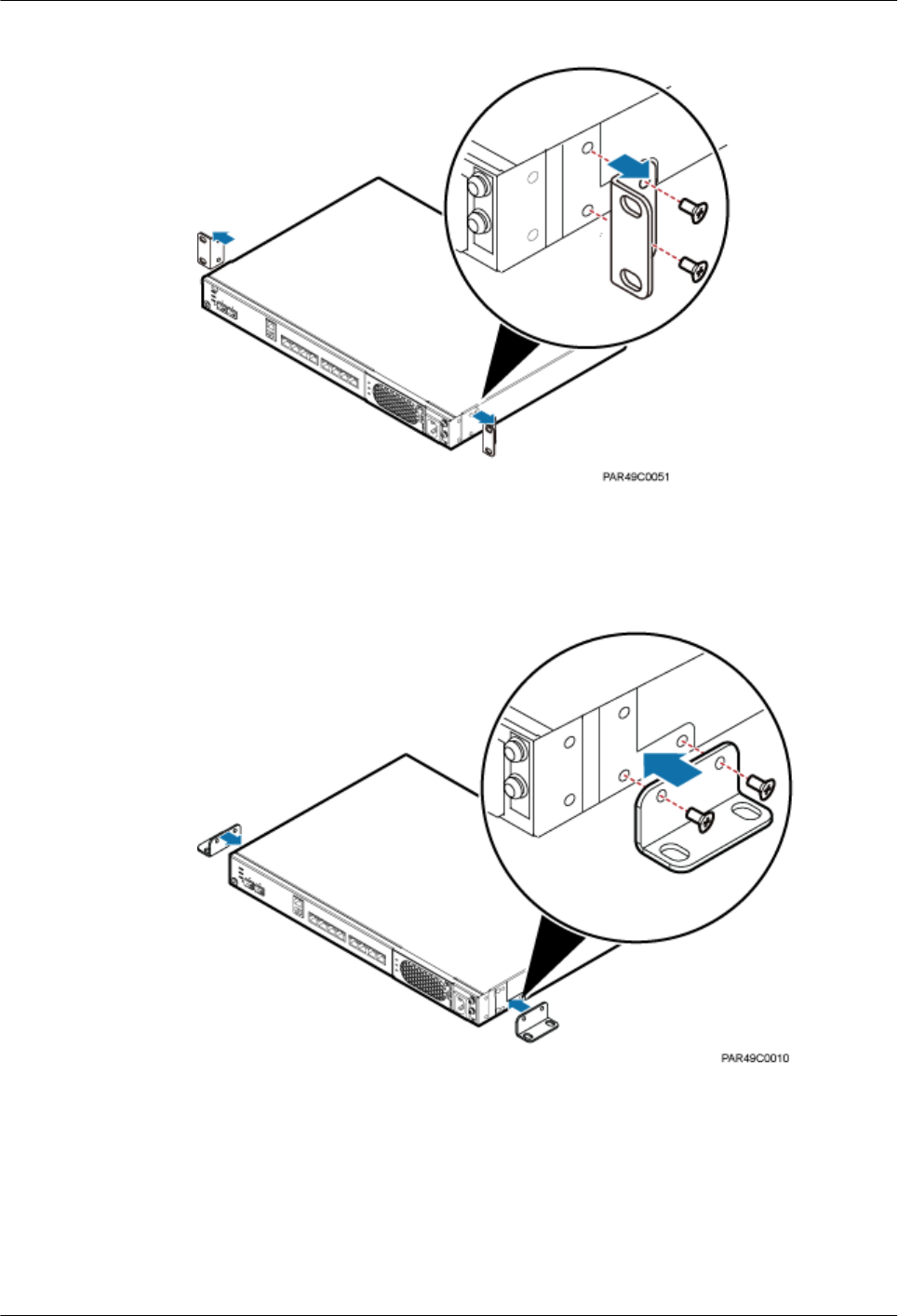
Figure 6-23 Removing screws and mounting ears
lRotate the mounting ears 90 degrees clockwise, and use a torque screwdriver or Phillips
screwdriver to secure the mounting ear with a torque of 1.4 N•m, as shown in Figure
6-24.
Figure 6-24 Installing mounting ears and screws
Step 2 Determine the position on the wall for installing the RHUB based on the requirements in the
engineering blueprint and 6.1.2 Installation Clearance Requirements. Place the RHUB to
the position to be installed against the wall, and then mark the four anchor points where the
mounting ear screws are fastened using a marker, as shown in Figure 6-25.
DBS3900 LampSite
Installation Guide 6 Installing an RHUB
Issue 07 (2015-12-30) Huawei Proprietary and Confidential
Copyright © Huawei Technologies Co., Ltd.
30
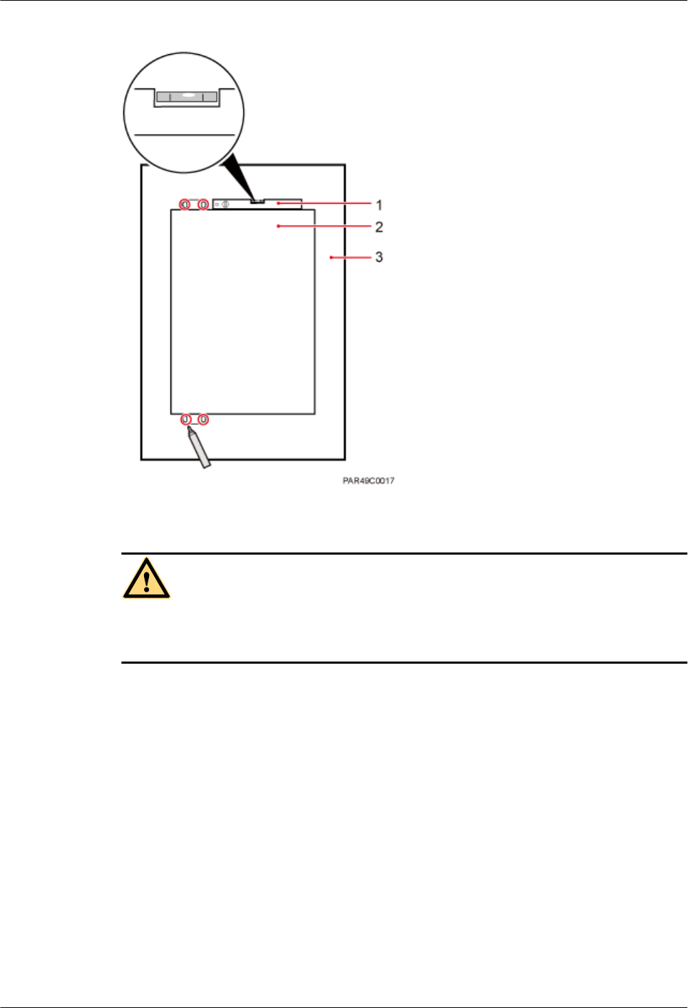
Figure 6-25 Anchor points for installing an RHUB on a wall
(1) Level (2) RHUB (3) Wall
CAUTION
To prevent inhalation or eye contact with dust, take adequate preventive measures when
drilling holes.
Step 3 Drill holes at the anchor point and install expansion bolts, as shown in Figure 6-26.
DBS3900 LampSite
Installation Guide 6 Installing an RHUB
Issue 07 (2015-12-30) Huawei Proprietary and Confidential
Copyright © Huawei Technologies Co., Ltd.
31
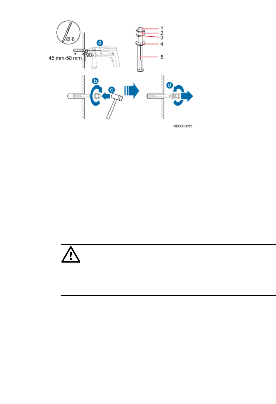
Figure 6-26 Drilling holes and installing expansion bolts
(1) M6×60
expansion bolt
(2) Nut (3) Spring washer (4) Flat washer (5) Extension tub
1. Use a hammer drill with bit 8 to drill holes with a diameter of 8 mm and a depth of 45
mm to 50 mm at the marked anchor points. All the holes have the same depth.
2. Use a vacuum cleaner to clear the dust inside and around each hole. If the distance
between two holes is incorrect, mark and drill holes again.
3. Partially tighten an expansion bolt and place it vertically into each hole.
4. Use a rubber mallet to hit the expansion bolt until the entire expansion sleeve is in the
hole.
5. Remove the M6×60 bolt, nut, spring washer, and flat washer from each expansion bolt in
sequence.
NOTICE
After removing an expansion bolt, ensure that the top of the expansion sleeve is level
with the wall. If it is not level, the RHUB cannot be installed on the concrete floor
evenly and securely.
Step 4 Align the mounting holes with the four M6×60 expansion bolts. Install spring washer 6 and
flat washer 6 in sequence on each M6×60 expansion bolt, insert the bolts to each expansion
tub, and then use a torque wrench or socket wrench to tighten the four M6×60 bolts with a
torque of 5 N•m to secure the RHUB to the wall, as shown in Figure 6-27.
DBS3900 LampSite
Installation Guide 6 Installing an RHUB
Issue 07 (2015-12-30) Huawei Proprietary and Confidential
Copyright © Huawei Technologies Co., Ltd.
32
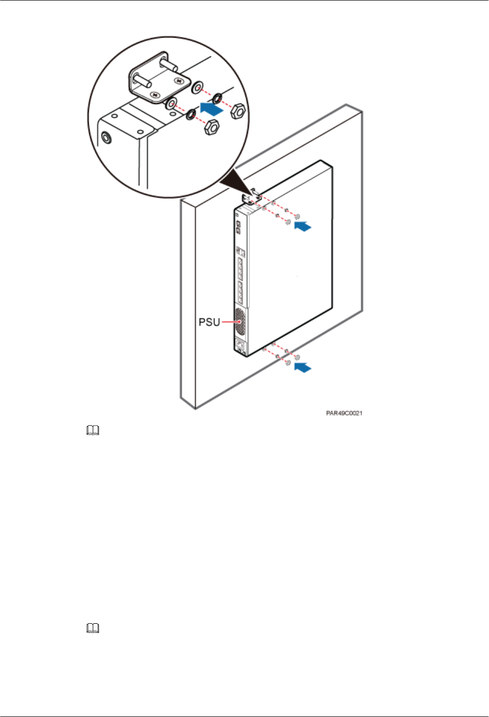
Figure 6-27 Installing an RHUB on a wall
NOTE
As shown in the preceding figure, when the RHUB is placed against the wall, ensure that the RHUB
panel is vertical to the ground and the PSU is on the lower part of the RHUB panel.
----End
6.4 Installing RHUB Cables
This section describes how to install cables for an RHUB.
6.4.1 Requirements for Cable Layout
Cables must be routed according to the specified cabling requirements to prevent signal
interference.
NOTE
If a cable listed below is not required, skip the requirements for routing the cable.
General Requirements for Cable Layout
National Standards
DBS3900 LampSite
Installation Guide 6 Installing an RHUB
Issue 07 (2015-12-30) Huawei Proprietary and Confidential
Copyright © Huawei Technologies Co., Ltd.
33

lCode for Engineering Design of Generic Cabling System for Building and Campus (GB
50311-2007)
lCode for Engineering Acceptance of Generic Cabling System for Building and Campus
(GB50312-2007).
lSecurity Protection Engineering Technology Specifications (GB 50348-2004)
lCode for Construction and Acceptance of the Electronic Information System Room (GB
50462-2008)
lCode for Quality Acceptance of the Intelligent Building Engineering (GB 50339-2003)
lCode for Quality Acceptance of Electric Engineering Construction in Building (GB
50303-2002)
lTechnical Specification for Construction and Acceptance of Telecommunication Conduit
Engineering (GB 50374-2006)
International Standards
lGeneric Cabling for Customer Premises (ISO/IEC 11801)
lCommercial Building Telecommunications Cabling Standard (EIA/TIA 568)
lCommercial Building Standard for Telecommunication Pathways and Spaces (EIA/TIA
569)
lAdministration Standard for Commercial Telecommunications Infrastructure (EIA/TIA
606)
lGrounding and Bonding Requirements for Telecommunications in Commercial
Buildings (EIA/TIA 607)
lGeneric Cabling Systems for Information Technology (EN 50173)
lCabling Installation for Information Technology (EN 50174)
Bending radius
lThe bending radius of a power cable or a protection ground (PGND) cable is at least five
times the diameter of the cable.
lThe bending radius of an optical cable is at least 20 times the diameter of the optical
cable, and the minimum bending radius of the branch at each end of the optical cable is
30 mm.
lThe bending radius of the signal cable must be at least five times the diameter of the
cable.
Cable Binding
lCables of the same type are bound together.
lDifferent types of cables must be separately routed with a minimum spacing of 30 mm
and cannot be entangled or crossed.
lThe cables are bound tightly and neatly and the cable sheath is intact.
lThe cable ties face the same direction and all cable ties bound at similar positions must
be in a straight line.
lThe extra length of each indoor cable tie must be cut off. A slack of 5 mm is reserved for
each outdoor cable tie. All cut surfaces have no sharp edges.
lLabels or nameplates are attached to both ends, joints, or turns of cables after they are
installed.
Safety
DBS3900 LampSite
Installation Guide 6 Installing an RHUB
Issue 07 (2015-12-30) Huawei Proprietary and Confidential
Copyright © Huawei Technologies Co., Ltd.
34

lThe steel pipe or fire-resistant rigid polyvinyl chloride pipe should be used for the cable
duct or for routing cables. The cross-sectional usage of the cable duct should be 30% to
50% and that of the pipe for routing cables should be 25% to 30%.
lCables are placed away from sharp objects or wall burrs. If these positions are inevitable,
protection pipes are required for the cables.
lCables are routed away from heat sources, or heat-insulation materials are added
between cables and heat sources.
lCables are routed away the cooling vents of the RHUB.
lA clearance is reserved at turns of a cable or the position close to a device, facilitating
cable and device maintenance. The recommended clearance is about 0.1 m.
Requirements for Special Cables
Ethernet Cable
lA maximum of 100 Ethernet cables can be bundled if no PVC pipes are used. If pipes are
used, a maximum of 24 Ethernet cables can be led through a pipe. In this case, ensure
that 1/3 space inside the pipes must be vacant.
lThe point at which an Ethernet cable is bundled must be spaced 400 mm or less from the
Ethernet port on an RHUB.
lFor the RHUB used in the elevator engine room on the rooftop, generator set for the
subway engine, and equipment room with central air conditioning, Ethernet cables must
be led through metallic conduits that are reliably grounded at both ends.
Power cable
lPositions for routing power cables meet requirements of the engineering design.
lCables are routed only by qualified and trained personnel before all preparations are
made.
lCables are routed in an untangled and orderly fashion.
PGND cable
lPGND cables are buried in the ground or routed indoors. They cannot be routed
overhead before they are routed into the equipment room.
lOuter conductors of coaxial cables and both ends of the shield layers on shielded cables
are in proper electrical contact with the metal surface of the equipment to which they are
connected.
lPGND cables and signal cables are installed in an untangled and orderly fashion. A
certain distance is reserved between them to prevent interference from each other.
lFuses or switches are not allowed on PGND cables.
lOther devices cannot be used for electrical connections of PGND cables.
lAll the metal parts in the equipment are reliably connected to the ground terminal.
Optical cable
lCables are routed in an untangled and orderly fashion.
lOptical fibers cannot be bound at turns.
lOptical fibers cannot be stretched with too much force or stepped on, and they are far
away from sharp objects. Heavy objects cannot be placed on optical cables.
lWhen optical cables are routed, the extra length of the cables is coiled around special
devices, such as a fiber coiler.
DBS3900 LampSite
Installation Guide 6 Installing an RHUB
Issue 07 (2015-12-30) Huawei Proprietary and Confidential
Copyright © Huawei Technologies Co., Ltd.
35
lEven strength is applied when optical cables are coiled and optical cables cannot be bent
in a forcible manner.
lVacant optical connectors are covered with dust-proof caps.
lFiber optic cables cannot be squeezed by the cabinet door when routed through the
cabinet.
lIf optical cables need to be routed on the tower platform, the optical cables are routed
along the inner side of the guard rail and the distance between the guard rail and the
cable is the shortest one.
lIf optical cables need to be routed close to a device on the tower, the optical cables are
secured to the guard rail or pole with cable clips and the device cannot be far away from
the position for securing the optical cables.
lIf the optical cable close to a device on the tower is too long, the optical cables are
wrapped and secured to the tower.
6.4.2 Cable List
This section describes the connector types and connections of the RHUB cables.
Table 6-3 lists RHUB cables.
Table 6-3 RHUB cable list
Cable One End The Other End
Connector Connected
to...
Connector Connected to...
PGND cable OT terminal
(M4, 6 mm2
[0.009 in.2])
Ground screws
on the RHUB
OT terminal
(M6, 6 mm2
[0.009 in.2])
Ground terminal
on the external
ground bar
Power
Supply Cable
C13 female
connector
AC power
input socket on
the RHUB
3-pin connector External power
input socket
CPRI Optical
Fiber
DLC connector CPRI port on
the LBBP,
WBBP or
UBBP in the
BBU
DLC connector CPRI0 or CPRI1
port on the
RHUB
CPRI port on
the LBBP,
WBBP or
UBBP in the
BBU
DLC connector CPRI port on the
DCU
CPRI port on
the DCU
CPRI0 or CPRI1
port on the
RHUB
DBS3900 LampSite
Installation Guide 6 Installing an RHUB
Issue 07 (2015-12-30) Huawei Proprietary and Confidential
Copyright © Huawei Technologies Co., Ltd.
36

Cable One End The Other End
Connector Connected
to...
Connector Connected to...
CPRI0 or
CPRI1 port on
the RHUB
DLC connector CPRI0 or CPRI1
port on the
RHUB
CPRI port on
the LBBP,
WBBP or
UBBP in the
BBU
FC connector,
SC connector, or
LC connector
ODF
CPRI port on
the DCU
CPRI0 or
CPRI1 port on
the RHUB
Ethernet
Cable
RJ45 connector CPRI_E0~CP
RI_E7 port on
the RHUB
RJ45 connector CPRI_E0~CPRI_
E1 port on the
pRRU
RJ45 connector CPRI_E0~CP
RI_E7 port on
the RHUB
RJ45 connector Protect port on
the PoE surge
protector 2
RJ45 connector Surge port on
the PoE surge
protector 2
RJ45 connector Surge port on the
PoE surge
protector 1
RJ45 connector Protect port on
the PoE surge
protector 1
RJ45 connector CPRI_E0~CPRI_
E1 port on the
pRRU3902
(Optional)
Alarm Cable
RJ45 connector EXT_ALM
port on the
RHUB
Bare end Alarm signal port
of the monitored
equipment
DBS3900 LampSite
Installation Guide 6 Installing an RHUB
Issue 07 (2015-12-30) Huawei Proprietary and Confidential
Copyright © Huawei Technologies Co., Ltd.
37
NOTE
lIf one end of the CPRI cable is connected to the DLC connector, the other end connects the BBU,
DCU or RHUB through the DLC connector. If one end of the CPRI cable is connected to the ODF
adapter, the other end connects the BBU or RHUB through a connector corresponding to the adapter.
The connectors include the FC connector, SC connector, and LC connector.
lThe Extender can be used to lengthen the distance between the RHUB and the pRRU connected
using the Ethernet cable. If the Extender is used, the Ethernet cable is divided into two parts, one
between the RHUB and the Extender and the other between the Extender and the pRRU.
l
lWhen the RHUB and the pRRU connected using the Ethernet cable. If the Extender is used,
lIn the indoor scenario, the Ethernet cable is divided into two parts, one between the RHUB
and the Extender and the other between the Extender and the pRRU.
lIn the outdoor scenario (only pRRU3901 and pRRU3902) , the Ethernet cable is divided into
two parts, one among RHUB-PoE surge protector 2- PoE surge protector 3-Extender and the
other among the Extender- PoE surge protector 4- PoE surge protector 1-pRRU.
6.4.3 Cable Connections
This section describes the cable connections for an RHUB.
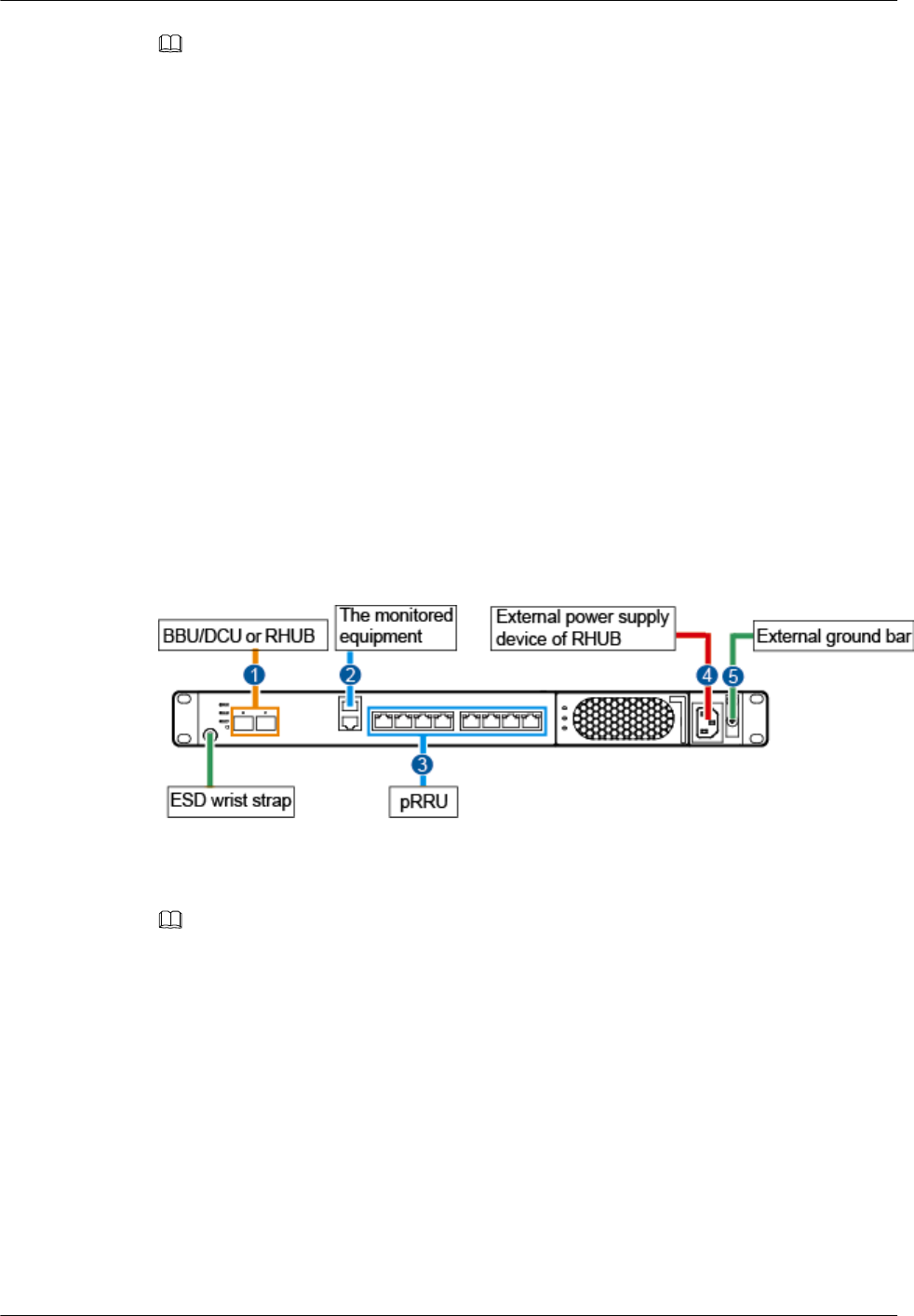
Figure 6-28, Figure 6-29 shows the cable connections for an RHUB. The port of ETH are
reserved.
Figure 6-28 Cable connections for an RHUB (indoor)
(1) CPRI optical cable (2) Alarm cable (3) Ethernet cable
(4) Power cable (5) PGND cable -
NOTE
The Extender can be used to lengthen the distance between the RHUB and the pRRU connected using
the Ethernet cable. If the Extender is used, the Ethernet cable is divided into two parts, one between the
RHUB and the Extender and the other between the Extender and the pRRU.
DBS3900 LampSite
Installation Guide 6 Installing an RHUB
Issue 07 (2015-12-30) Huawei Proprietary and Confidential
Copyright © Huawei Technologies Co., Ltd.
38
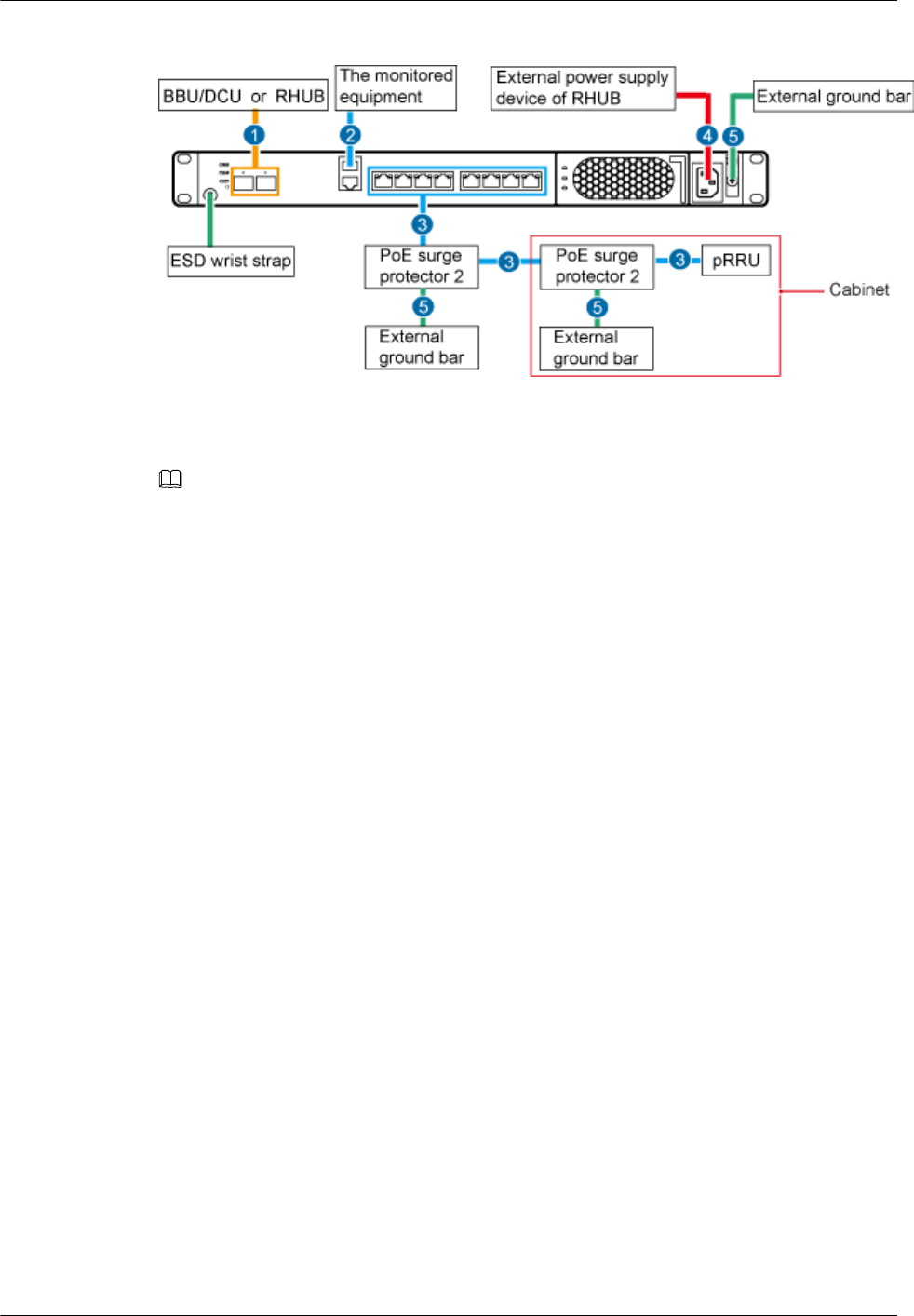
Figure 6-29 Cable connections for an RHUB (outdoor)
(1) CPRI optical cable (2) Alarm cable (3) Ethernet cable
(4) Power cable (5) PGND cable -
NOTE
The Extender can be used to lengthen the distance between the RHUB and the pRRU connected using
the Ethernet cable. If the Extender is used, the Ethernet cable is divided into two parts, one between the
RHUB and the Extender and the other between the Extender and the pRRU.
6.4.4 Cable Installation Process
This section describes the process of installing RHUB cables.
Figure 6-30 shows the RHUB cable installation process.
DBS3900 LampSite
Installation Guide 6 Installing an RHUB
Issue 07 (2015-12-30) Huawei Proprietary and Confidential
Copyright © Huawei Technologies Co., Ltd.
39
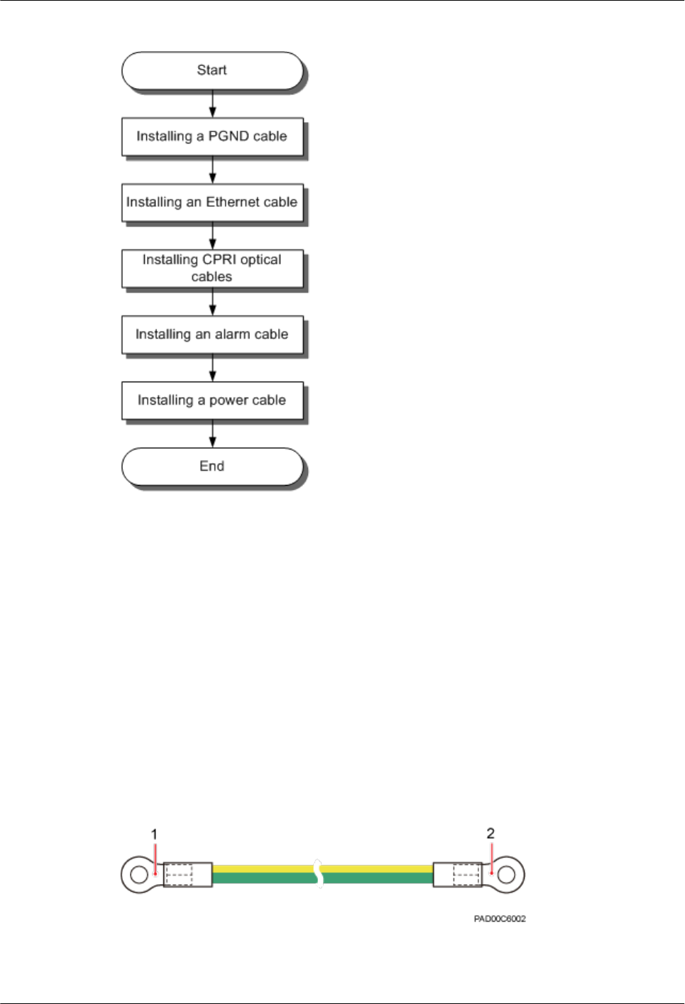
Figure 6-30 RHUB cable installation process
6.4.5 Installing PGND Cable
An RHUB PGND cable ensures proper grounding of an RHUB.
Prerequisites
The OT terminals at both ends of the PGND cable are prepared.
Context
The yellow and green or green PGND cable is a single cable. The cross-sectional area of the
PGND cable is 6 mm2 (0.009 in.2). Both ends of the cable are OT terminals, as shown in
Figure 1.
Figure 6-31 Exterior of a PGND cable
(1) OT terminal (6 mm2 [0.009 in.2], M4) (2) OT terminal (6 mm2 [0.009 in.2], M6)
DBS3900 LampSite
Installation Guide 6 Installing an RHUB
Issue 07 (2015-12-30) Huawei Proprietary and Confidential
Copyright © Huawei Technologies Co., Ltd.
40
NOTE
lIf the PGND cable is provided by the customer, a copper-core cable with a minimum cross-sectional
area of 6 mm2 (0.009 in.2) or 10 AWG is recommended.
lThe OT terminals at both ends of the PGND cable are assembled at the site.
lThe M6 OT terminal has the default size. You can replace it with another OT terminal of the
expected size based on the site requirement.
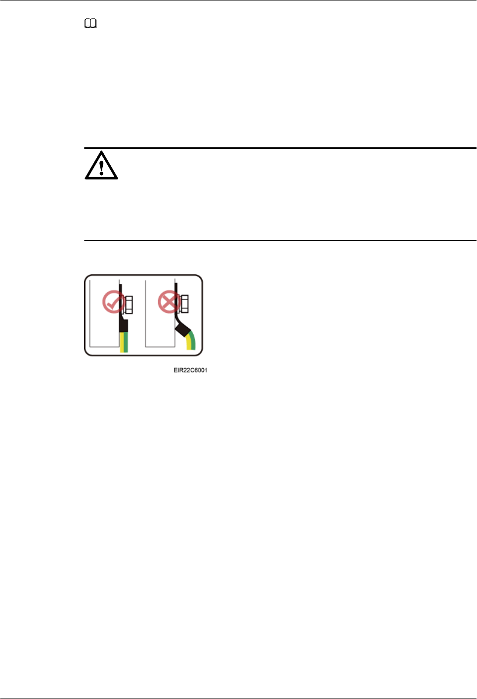
NOTICE
lEnsure proper grounding of the RHUB using a PGND cable.
lWhen installing the PGND cable, tightly press the OT terminal in the correct direction, as
shown in Figure 6-32.
Figure 6-32 Correct direction of an OT terminal for the PGND cable
Procedure
Step 1 Route the PGND cable by referring to 6.4.1 Requirements for Cable Layout.
Step 2 Use a torque screwdriver or Phillips screwdriver to secure the M4 OT terminal at one end of
the PGND cable to the ground screw on the RHUB panel with a torque of 1.4 N•m. If the OT
terminal is a one-hole OT terminal, connect it to the ground screw on the lower part of the
RHUB panel, as shown in Figure 6-33.
DBS3900 LampSite
Installation Guide 6 Installing an RHUB
Issue 07 (2015-12-30) Huawei Proprietary and Confidential
Copyright © Huawei Technologies Co., Ltd.
41
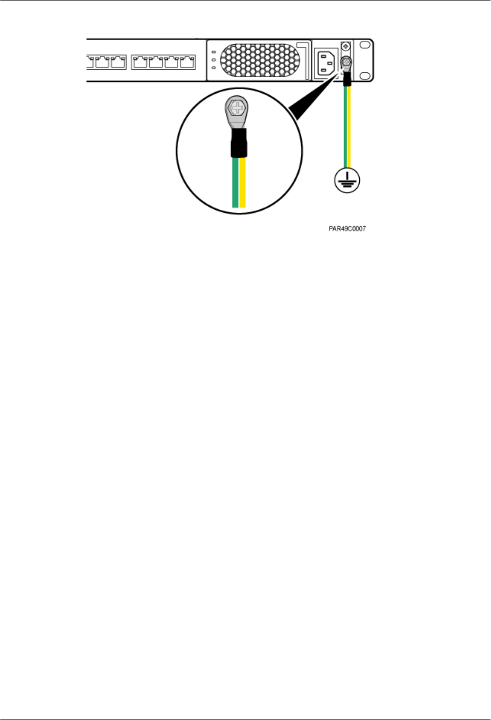
Figure 6-33 Installing an RHUB PGND cable
Step 3 Use a torque screwdriver or Phillips screwdriver to secure the M8 OT terminal at one end of
the PGND cable to the wiring terminal on the ground bar at the site with a torque of 1.4 N•m.
----End
Follow-up Procedure
1. Route the cable, and then use a cable tie to bind the cable. For details, see 6.4.1
Requirements for Cable Layout.
2. Label the installed cable. For details, see section 14.4 Attaching an L-Shaped Label.
6.4.6 Installing Ethernet Cable
This section describes how to install an Ethernet cable.
Prerequisites
lThe Ethernet cable must be of Category 5e (enhanced) or higher. In addition, its cross-
sectional area must be 24 AWG or larger and frame spread rating must be CM or higher.
lThe Ethernet cables can be straight-through cables or crossover cables.
lWith the internal PoE module providing power, the maximum length of an Ethernet
cable is 100 m. With the Extender, the distance of the pRRU and RHUB can be extended
by the Extender up to a total distance of 200 m.
lEthernet cables are not delivered, and they must be prepared onsite. You need to use a
network cable tester to test the Ethernet cable connection.
Context
The Ethernet cable has the following functions:
lProvides power supply for the pRRU when connected to the CPRI_E0 port on the
pRRU.
lTransmits CPRI signals between an RHUB and a pRRU.
For details about the cable connections in the different scenarios, see 6.4.3 Cable
Connections. The Ethernet cable connections between RHUB and pRRUs are the same. The
DBS3900 LampSite
Installation Guide 6 Installing an RHUB
Issue 07 (2015-12-30) Huawei Proprietary and Confidential
Copyright © Huawei Technologies Co., Ltd.
42
following section describes the connections between RHUB-Extender-pRRU3901 as an
example.
In the outdoor scenario, PoE surge protector is needed to provide surge protection for the
Ethernet ports. For details about the installation of PoE surge protector, see 10 (Optional)
Installing the PoE Surge Protector and Cables.
Procedure
Step 1 Make the Ethernet cables.
1. Assemble an RJ45 connector and an Ethernet cable by following instructions in
Assembling the Unshielded RJ45 Connector and the Ethernet Cable of Installation
Reference.
NOTE
Follow pin assignment instructions described in section Ethernet Cable in DBS3900 LampSite
Hardware Description to assemble the unshielded RJ45 connector and the Ethernet cable. Otherwise,
the transmission signal quality deteriorates and CPRI links may be disconnected.
2. Check whether the made RJ45 connector is qualified by following instructions in
Checking the Appearance of Metal Contact Strips.
3. To complete the assembly of the other end, repeat Step 1.1 and Step 1.2.
4. Check whether the touch points on the connectors at both ends are normally conducted
and well contacted and whether the connections are correct by following instructions in
Testing the Connection of Assembled Cables of Installation Reference.
Step 2 Connect the RJ45 connector at the other end of the Ethernet cable to any port ranging from
CPRI_E0 to CPRI_E7 on the RHUB panel based on the engineering design.
Step 3 Optional: Connect the RJ45 connector at the other end of the Ethernet cable to the output
port of the Extender. Then, connect the RJ45 connector at one end of another Ethernet cable
to the input port of the Extender.
If the Extender is used, the Ethernet cable is divided into two parts, one between the RHUB
and the Extender and the other between the Extender and the pRRU.
Step 4 Remove the dustproof cap of the CPRI_E0 port on the pRRU.
Step 5 Connect the RJ45 connector at one end of the Ethernet cable to the CPRI_E0 port on the
pRRU panel, as shown in Figure 6-34, Figure 6-35.
Figure 6-34 Install an Ethernet cable between an RHUB and a pRRU3901
(1) Ethernet cable (2) CPRI_E0 port on the pRRU3901
DBS3900 LampSite
Installation Guide 6 Installing an RHUB
Issue 07 (2015-12-30) Huawei Proprietary and Confidential
Copyright © Huawei Technologies Co., Ltd.
43
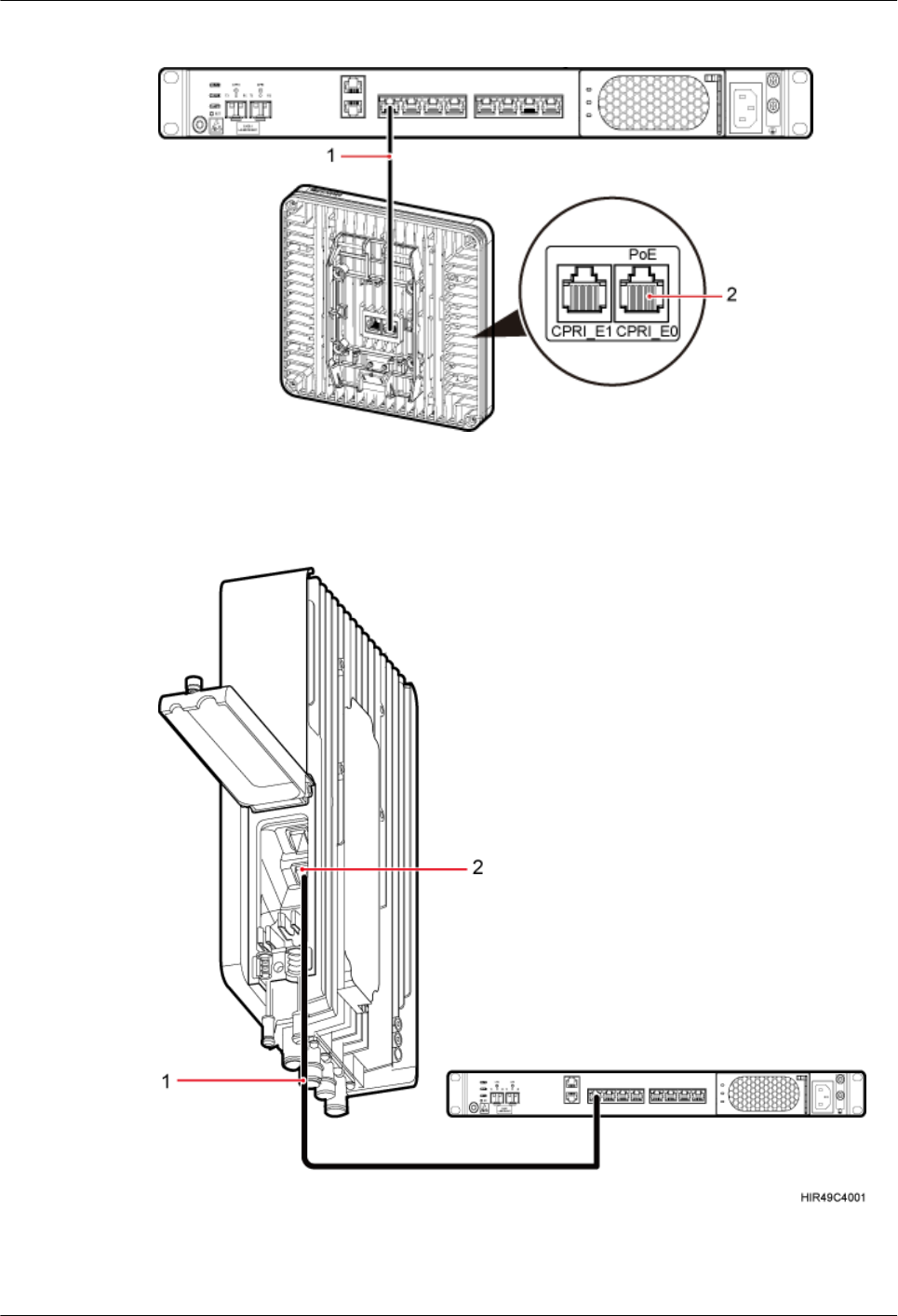
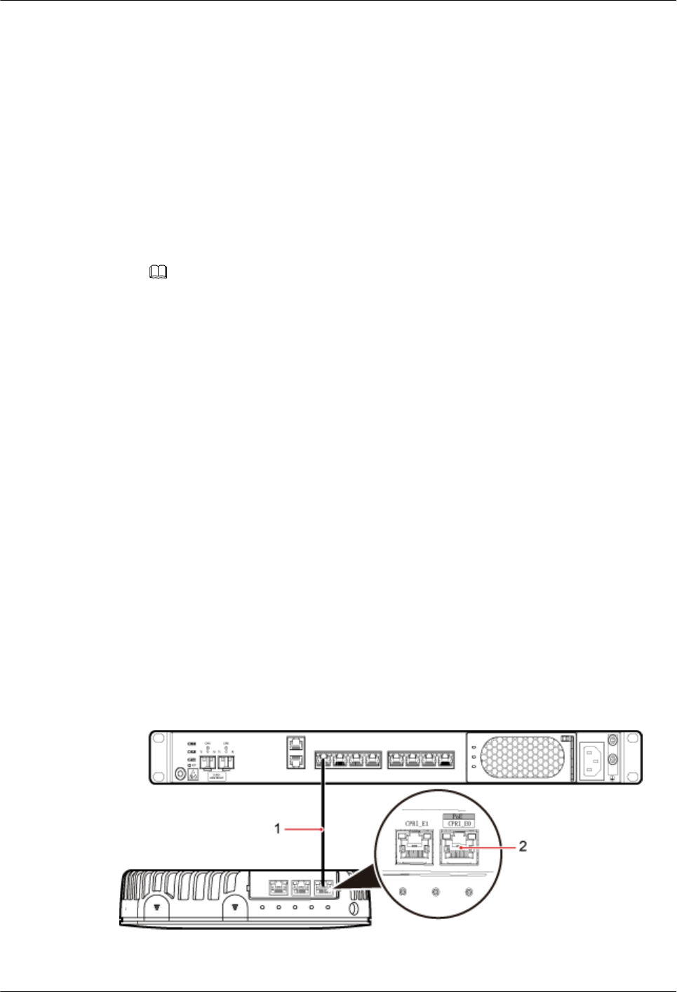
Figure 6-35 Install an Ethernet cable between an RHUB and a pRRU3902 or pRRU3911
(1) Ethernet cable (2) CPRI_E0 port on the pRRU3902
Figure 6-36 Install an Ethernet cable between an RHUB and a pRRU3907
(1) Ethernet cable (2) CPRI_E0 port on the pRRU
DBS3900 LampSite
Installation Guide 6 Installing an RHUB
Issue 07 (2015-12-30) Huawei Proprietary and Confidential
Copyright © Huawei Technologies Co., Ltd.
44
----End
Follow-up Procedure
1. Route the cable, and then use a cable tie to bind the cable. For details, see 6.4.1
Requirements for Cable Layout.
2. Label the installed cable. For details, see section 14.4 Attaching an L-Shaped Label.
6.4.7 Installing CRPI Optical Cables
Optical fibers can be used to interconnect BBU and RHUBs, or cascade RHUBs.
Context
lMulti-mode optical modules for CPRI ports are labeled MM and each has a black or gray
puller.
lSingle-mode optical modules are labeled SM and each has a blue puller.
lFor details about the connection of CPRI optical cables, see CPRI Topology in
DBS3900 LampSite Technical Description.
lAn optical module to be installed must match the rate of its corresponding port.
NOTE
The performance of an optical module that is exposed to the air for more than 20 minutes may be abnormal.
Therefore, you must insert a fiber optic cable into an unpacked optical module within 20 minutes.
Procedure
Step 1 Install an optical module, as shown in Figure 6-37 and Figure 6-38.
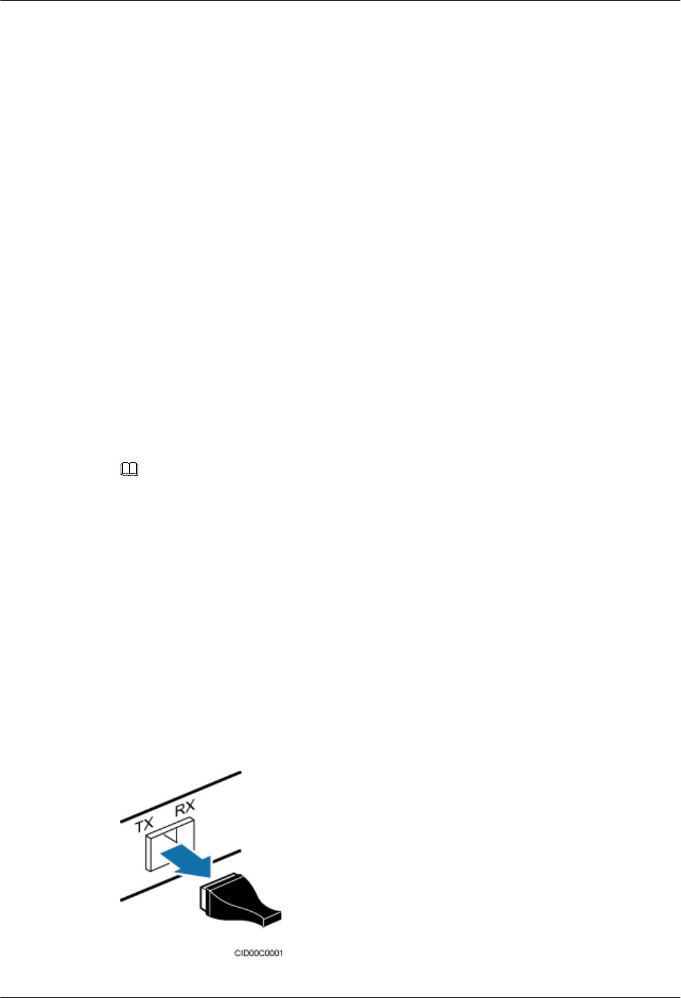
1. Remove the dust-proof cap from the CPRI port on the RHUB panel.
2. Remove the dust-proof cap on the optical module.
3. Lower the puller of the optical module.
4. Insert the optical module into the CPRI port on the RHUB, DCU, BBU or ODF.
5. Raise the puller of the optical module.
Figure 6-37 Removing the dust-proof cap from a port
DBS3900 LampSite
Installation Guide 6 Installing an RHUB
Issue 07 (2015-12-30) Huawei Proprietary and Confidential
Copyright © Huawei Technologies Co., Ltd.
45
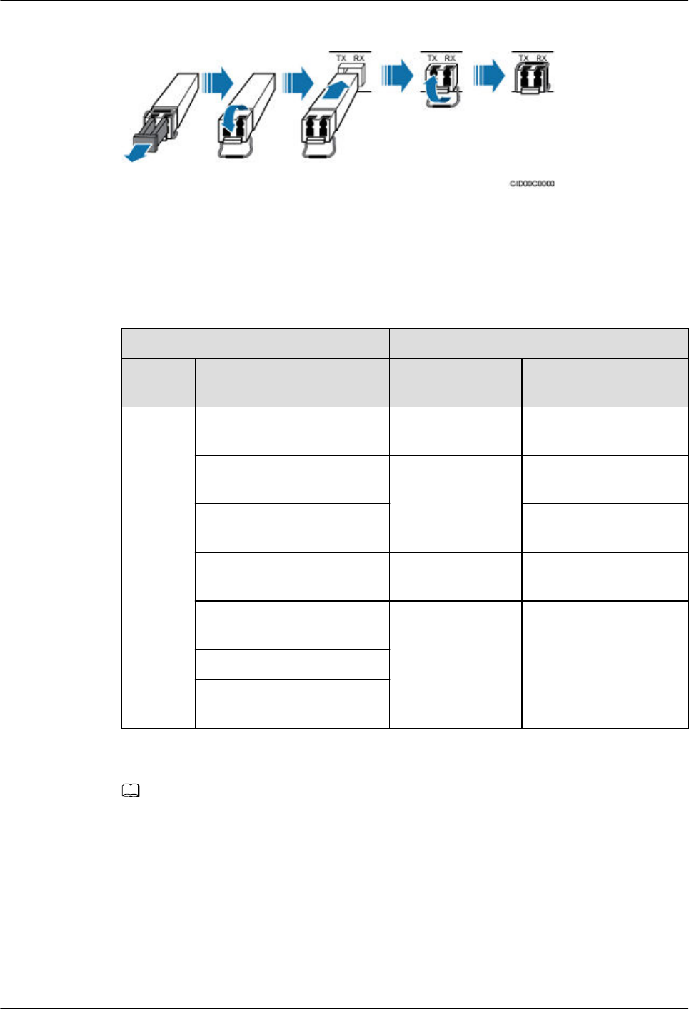
Figure 6-38 Installing an optical module
Step 2 Install a CPRI optical cable, as shown in Figure 6-39.
1. Remove the dust-proof cap from the optical cable connector.
2. Install the optical cables by referring to Table 6-4.
Table 6-4 CPRI optical cable connections
One End The Other End
Connect
or
Connected to Connector Connected to
DLC
connecto
r
BBU/LBBP&WBBP/CPRI
port
DLC connector CPRI0 or CPRI1 port on
the RHUB
BBU/LBBP&WBBP/CPRI
port
DLC connector CPRI port on the DCU
CPRI port on the DCU CPRI0 or CPRI1 port on
the RHUB
CPRI0 or CPRI1 port on the
RHUB
DLC connector CPRI0 or CPRI1 port on
the RHUB
BBU/LBBP&WBBP/CPRI
port
FC, SC, or LC
connector
ODF
CPRI port on the DCU
CPRI0 or CPRI1 port on the
RHUB
NOTE
lIn sharing BBUs with Macro Networks scenario, RHUBs share only main control boards with with
RF modules on macro base stations, not baseband processing units.
lIf one end of the CPRI cable is connected to the DLC connector, the other end connects the BBU or
RHUB through the DLC connector. If one end of the CPRI cable is connected to the ODF adapter,
the other end connects the BBU/DCU or RHUB through a connector corresponding to the adapter.
The connectors include the FC connector, SC connector, and LC connector.
lWhen connecting the CPRI cable to the TX and RX ports of the optical module through connectors
in a cross manner, ensure that one end of a core of the CPRI cable is connected to the TX port and
the other end is connected to the RX port. Figure 6-39 shows how to install a CPRI optical cable for
connecting the BBU and RHUBs.
DBS3900 LampSite
Installation Guide 6 Installing an RHUB
Issue 07 (2015-12-30) Huawei Proprietary and Confidential
Copyright © Huawei Technologies Co., Ltd.
46
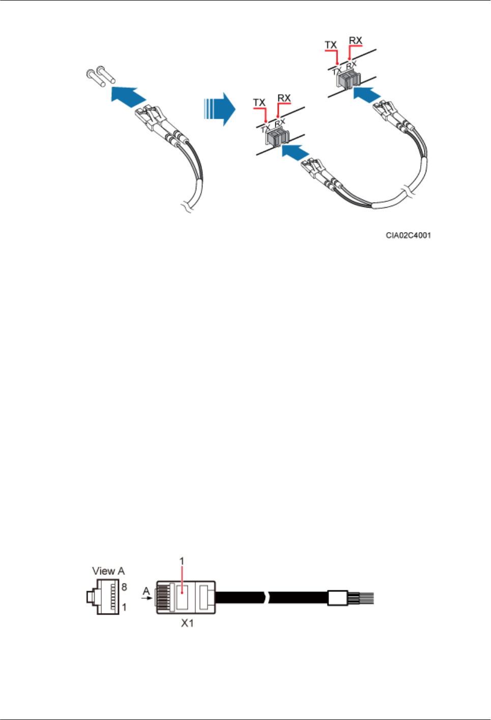
Figure 6-39 Installing an CRPI optical cable
----End
Follow-up Procedure
1. Route the cable, and then use a cable tie to bind the cable. For details, see 6.4.1
Requirements for Cable Layout.
2. Label the installed cable. For details, see section 14.4 Attaching an L-Shaped Label.
6.4.8 Installing Alarm Cable (Optional)
An RHUB alarm cable transmits dry node alarm signals.
Prerequisites
Connectors for an alarm cable are prepared.
Context
Figure 6-40 shows the exterior of an RHUB alarm cable. 6.4.2 Cable List shows the
installation position on both ends of the RHUB cable.
Figure 6-40 RHUB alarm cable
Procedure
Step 1 Connect the RJ45 connector on one end of the alarm cable to the EXT_ALM port on the
RHUB.
DBS3900 LampSite
Installation Guide 6 Installing an RHUB
Issue 07 (2015-12-30) Huawei Proprietary and Confidential
Copyright © Huawei Technologies Co., Ltd.
47
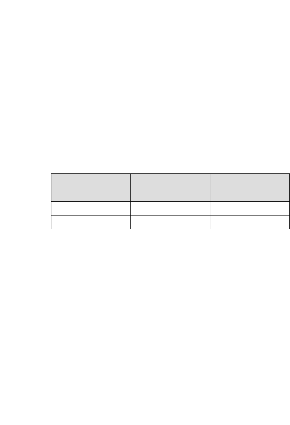
Step 2 Connect the other end of the alarm cable to the alarm cable port on the device to be
monitored.
----End
Follow-up Procedure
1. Route the cable, and then use a cable tie to bind the cable. For details, see 6.4.1
Requirements for Cable Layout.
2. Label the installed cable. For details, see section 14.4 Attaching an L-Shaped Label.
6.4.9 Installing Power Cable
The RHUB power cable provides 110 V AC/220 V AC power supply for the RHUB.
Context
Table 6-5 lists the recommended configurations of upper-level circuit breakers and power
cables for a RHUB.
Table 6-5 Configurations of upper-level circuit breakers and power cables
Power Supply Upper-level AC Circuit
Breaker (For a single
RHUB)
Cross-Sectional Area of
the Input Power Cable
220 V AC single-phase ≥ 6 A 1 mm2
110 V AC single-phase ≥ 10 A 1.25 mm2
Procedure
Step 1 Route the power cable by referring to 6.4.1 Requirements for Cable Layout.
Step 2 Connect the power connector on the X1 end to the AC power input port on the RHUB panel,
as shown in Figure 6-41.
Step 3 Connect the power connector on the X2 end to the external power supply port, as shown in
Figure 6-41.
DBS3900 LampSite
Installation Guide 6 Installing an RHUB
Issue 07 (2015-12-30) Huawei Proprietary and Confidential
Copyright © Huawei Technologies Co., Ltd.
48
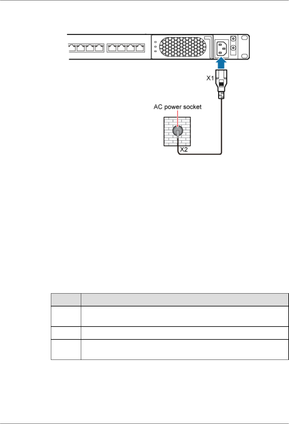
Figure 6-41 Installing an RHUB power cable
----End
Follow-up Procedure
1. Route the cable, and then use a cable tie to bind the cable. For details, see 6.4.1
Requirements for Cable Layout.
2. Label the installed cable. For details, see section 14.4 Attaching an L-Shaped Label.
6.5 Checking the RHUB Hardware Installation
After an RHUB is installed, check the installation of hardware including the devices and
related cables.
Table 6-6 lists the hardware installation checking items.
Table 6-6 Hardware installation checking list
No. Item
1 The position for each device conforms to the engineering design and meets the
space requirement.
2 Ensure that the RHUB is properly installed.
3 The surface of the RHUB is neat and clean. The external paint is intact. The
labels, tags, and nameplates are correct, legible, and complete.
Table 6-7 lists the checking list of the power cable and PGND cable connections.
DBS3900 LampSite
Installation Guide 6 Installing an RHUB
Issue 07 (2015-12-30) Huawei Proprietary and Confidential
Copyright © Huawei Technologies Co., Ltd.
49
Table 6-7 Checklist for power cable and PGND cable connections
No. Item
1 The power cables and PGND cables comply with the requirements of local
regulations.
2 The power cables or the PGND cables are not inversely connected or short-
circuited.
3 The power cables and PGND cables are bound separately from other cables.
4 Labels are attached to both ends of the power cables, PGND cables, optical
fibers, and Ethernet cables.
5 The power cables and PGND cables are intact.
6 The power cables and PGND cables have no weld nugget.
7 No breaking device such as a switch or fuse lies in the electric connection of
the grounding system.
8 The redundant part of PGND cable is stripped off.
9 The lugs at both ends of the power cable or PGND cable are securely soldered
or crimped.
10 The flat washers and spring washers are fixed securely and closely at all the
wiring terminals.
11 The work GND cable and PGND cable of the BTS share a group of grounding
conductors with the lightning and GND cables of the building.
Table 6-8 lists the check items of the signal cable connection.
Table 6-8 Checklist for the signal cable connection
No. Item
1 The connectors of the signal cables must securely connected.
2 The connectors of the signal cables are intact.
3 The signal cables are intact.
4 The cable ties are evenly spaced. The signal cables are bound neatly with cable
ties to proper tightness, and arranged at even intervals in the same direction.
5 The extra length of the cable ties is cut and removed. The cut surfaces of the
indoor cables are smooth and have no sharp edges.
6 The cable layout facilitates maintenance and expansion.
7 Correct and clear labels are attached to both ends of the signal cables.
DBS3900 LampSite
Installation Guide 6 Installing an RHUB
Issue 07 (2015-12-30) Huawei Proprietary and Confidential
Copyright © Huawei Technologies Co., Ltd.
50
No. Item
8 The distance between the bundled fiber tails and the RHUB panel is less than
70 mm.
Table 6-9 lists the checking items for other cable connections.
Table 6-9 Checklist for other cable connections
No. Item
1 The connectors of the other cables must securely connected.
2 Labels on the cables are legible and bound based on the engineering
requirements. The cables must be bound tightly and neatly. The sheaths of the
cables must not be damaged.
3 Positions for routing the cables must meet requirements of the engineering
design.
6.6 Power-on Check on an RHUB
This section describes the power-on check on the RHUB after the RHUB hardware is
installed and checked.
Context
After the RHUB and pRRUs are installed and connected to each other, power on them no
matter whether the BBU is installed.
DANGER
Power-on check involves high-voltage operation. Be cautious when conducting the power-on
check. Any direct contact with the input voltage or indirect contact through damp objects
might endanger your life.
Procedure
Step 1 Measure the RHUB earth resistance.
If... Then...
The RHUB earth resistance is less than
10 ohms
Go to Step 2.
The RHUB earth resistance is equal to
or larger than 10 ohms
Find out the cause and ensure that the resistance
meets requirement. Then, go to Step 2.
DBS3900 LampSite
Installation Guide 6 Installing an RHUB
Issue 07 (2015-12-30) Huawei Proprietary and Confidential
Copyright © Huawei Technologies Co., Ltd.
51
Step 2 Measure the voltage of the RHUB.
If... Then...
The external power supply ranges from
100 V AC to 240 V AC
Go to Step 3.
The external power supply does not
range from 100 V AC to 240 V AC
Find out the cause and ensure that the resistance
meets requirement. Then, go to Step 3.
Step 3 Power on the RHUB. Wait 3 to 5 minutes, check the status of the RUN indicator of the RHUB
after the RHUB runs properly.
If the Status of
the RUN
Indicator...
It Indicates that... Then...
Steady on The power supply is
normal while the board
is faulty.
Power off the RHUB, and power on it again
after rectifying the board fault.
Steady off There is no power input
or the board is faulty.
Power off the RHUB, and check the power
input again. Rectify the board faulty and
power on the RHUB again if the power
input is normal.
On for 1s and off
for 1s
The devices work
properly.
End the operation.
On for 0.125s
and off for 0.125s
The board software is
being uploaded.
Power off the RHUB if the uploading is not
finished in 5 minutes, and check whether
the configuration file is correct. Power on
the RHUB again after the fault is rectified.
NOTE
If an RHUB is not connected to any BBU, the RHUB is considered normally powered on when any indicator
on the RHUB is on.
----End
DBS3900 LampSite
Installation Guide 6 Installing an RHUB
Issue 07 (2015-12-30) Huawei Proprietary and Confidential
Copyright © Huawei Technologies Co., Ltd.
52

7 Installing a pRRU3901
About This Chapter
This chapter describes the pRRU3901 installation process. The pRRU3901 can have two
transmission ports (plus PWR port) or three transmission ports (plus PWR port or no PWR
port). Unless otherwise specified, this document uses the pRRU3901 with three transmission
ports plus no PWR port as an example.
7.1 Information About the Installation
This section describes the information that you must be familiar with before installing a
pRRU3901, including the pRRU3901 product family, installation scenarios, installation space
and environment requirements.
7.2 Obtaining the MAC Address (Optional)
Before installing a pRRU3901, record the media access control (MAC) address, which will be
used during pRRU3901 commissioning. This section applies only when a pRRU3901 with
three transmission ports is configured with a Wi-Fi daughter board.
7.3 Installation Process
This section describes the pRRU3901 installation process, which involves installing a
pRRU3901, and cables, checking the pRRU3901 hardware installation, and powering on the
pRRU3901.
7.4 Installing a pRRU3901
This section describes the pRRU3901 installation process. A pRRU3901 can be installed on a
wall, ceiling, indoor metal pole, or standard keel, but not on an aluminum panel or a non-
standard keel.
7.5 Installing pRRU3901 Cables
This section describes the procedure of installing the pRRU3901 cables.
7.6 Checking the pRRU3901 Hardware Installation
pRRU3901 hardware installation checking includes hardware and cable installation checking.
7.7 Powering on the pRRU3901
This section describes the power-on check on the pRRU3901 after the pRRU3901 hardware is
installed and checked.
DBS3900 LampSite
Installation Guide 7 Installing a pRRU3901
Issue 07 (2015-12-30) Huawei Proprietary and Confidential
Copyright © Huawei Technologies Co., Ltd.
53

7.1 Information About the Installation
This section describes the information that you must be familiar with before installing a
pRRU3901, including the pRRU3901 product family, installation scenarios, installation space
and environment requirements.
7.1.1 Product Family
This chapter describes the configurations and functions of the pRRU3901 components.
Table 7-1 lists the pRRU3901 product family.
Table 7-1 pRRU3901 product family
Category Equip
ment
Optional or
Mandatory
Quantity Function
Main
equipment
pRRU
3901
Mandatory 1 Processes the radio
frequency signals.
Extern
al
antenn
a
Optional 2 Provides external
antennas for the
pRRU3901.
NOTE
Configure two external
antennas for each RF
daughter board.
Auxiliary
device
Mounti
ng kits
Mandatory 1 Supports the pRRU3901
installation on a wall,
pole, ceiling, or keel.
The mounting kits vary
with the pRRU3901
installation mode.
Cabine
t
Optional lNone and one
Extender is
needed
lYes and two
Extenders are
needed
Install the pRRU3901
and Extender in the
outdoor scenario.
Extend
er
Optional 1 or 2
NOTE
The quantity depends
on the number of
Ethernet cables in use.
Extends the distance
between the pRRU3901
and RHUB.
DBS3900 LampSite
Installation Guide 7 Installing a pRRU3901
Issue 07 (2015-12-30) Huawei Proprietary and Confidential
Copyright © Huawei Technologies Co., Ltd.
54
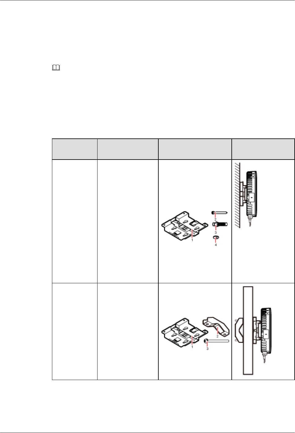
7.1.2 Installation Scenario
The pRRU3901 can be installed on a wall, ceiling, pole, or keel. The following table describes
the installation in different scenarios.
Installing a pRRU3901 on a wall
NOTE
lThe pRRU3901 must keep a minimum of 0.5 m away from the power equipment with interference,
and keep a minimum of 2 m away from the source with radiation.
lThe pRRU3901 must keep away from a metal wall to avoid the impact on the antenna performance.
When a pRRU3901 is installed on a wall, installation modes vary with the quality of wall, as
shown in Table 7-2.
Table 7-2 Wall-mounted suggestion
Installation
Mode
Requirements Mounting Brackets Installation
Diagram
Installing the
pRRU3901 on
a wall by
drilling holes
For details, see
7.4.2
Installing a
pRRU3901 on
a Wall.
lThe wall can
bear a load at
least four times
the weight of a
pRRU3901.
lThe screws must
be tightened with
a torque of 10
N·m. This
ensures the
screws work
properly and the
wall remains
intact without
cracks in it.
1. Plate
2. Screw (M6X50)
3. Plastic expansion
sleeve
4. Flat washer
Installing the
pRRU on a
wall using a V
clamp through
an attachment
plate
For details, see
7.4.5
Installing a
pRRU3901 on
a Plate.
lThe wall can
bear a load at
least four times
the weight of a
pRRU3901.
lThe thickness of
the wall is less
than 80 mm.
1. Plate
2. V clamp
3. Bolt (M6X80)
DBS3900 LampSite
Installation Guide 7 Installing a pRRU3901
Issue 07 (2015-12-30) Huawei Proprietary and Confidential
Copyright © Huawei Technologies Co., Ltd.
55
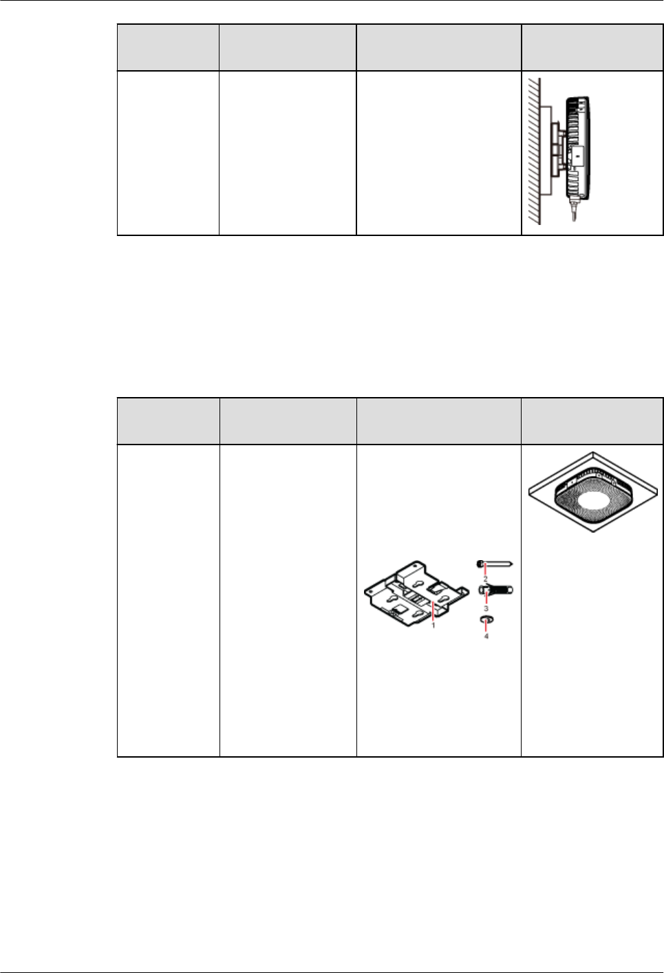
Installation
Mode
Requirements Mounting Brackets Installation
Diagram
Installing the
pRRU3901 on
a wall using a
plate on a
metal wall
The wall cannot bear
a load at least four
times the weight of
the pRRU. For
example, EPS walls,
MDF walls, or walls
cannot be drilled.
The plate is prepared by
customers.
Installing a pRRU3901 on a ceiling
When a pRRU3901 is installed on a ceiling, installation modes vary with the quality of the
ceiling, as shown in Table 7-3.
Table 7-3 Ceiling-mounted suggestion
Installation
Mode
Requirements Mounting Brackets Installation
Diagram
Installing the
pRRU3901 on
a ceiling by
drilling holes
For details, see
7.4.3
Installing a
pRRU3901 on
a Ceiling.
lThe ceiling, such
as a concrete
ceiling, can bear
a load at least
four times the
weight of the
pRRU3901.
lThe screws must
be tightened with
a torque of 10
N·m. This
ensures the
screws work
properly and the
ceiling remains
intact without
cracks in it.
1. Plate
2. Screw (M6X50)
3. Plastic expansion
sleeve
4. Flat washer
DBS3900 LampSite
Installation Guide 7 Installing a pRRU3901
Issue 07 (2015-12-30) Huawei Proprietary and Confidential
Copyright © Huawei Technologies Co., Ltd.
56
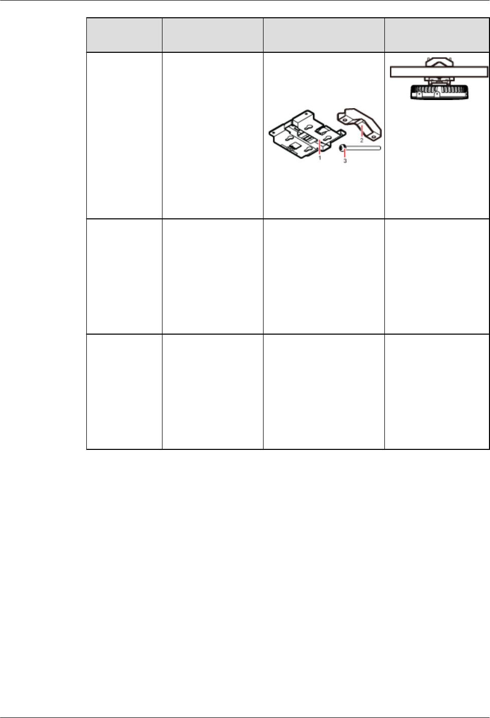
Installation
Mode
Requirements Mounting Brackets Installation
Diagram
Installing the
pRRU3901 on
a ceiling using
a V clamp
through an
attachment
plate
For details, see
7.4.5
Installing a
pRRU3901 on
a Plate.
lThe ceiling, such
as a concrete
ceiling, can bear
a load at least
four times the
weight of the
pRRU3901.
lThe thickness of
the ceiling is less
than 80 mm.
1. Plate
2. V clamp
3. Bolt (M6X80)
Installing the
pRRU3901 on
a pole
For details, see
7.4.4
Installing a
pRRU3901 on
a Pole.
A pole under the
ceiling can bear a
load at least four
times the weight of
the pRRU3901.
For details, see Table
7-4.
For details, see Table
7-4.
Installing the
pRRU3901 on
a keel
For details, see
7.4.6
Installing a
pRRU3901 on
a Keel.
A keel under the
ceiling can bear a
load at least four
times the weight of
the pRRU3901.
For details, see Table
7-5.
For details, see Table
7-5.
Installing the pRRU3901 on a pole
When a pRRU3901 is installed on a pole, installation modes vary with the diameter of the
pole, as shown in Table 7-4.
DBS3900 LampSite
Installation Guide 7 Installing a pRRU3901
Issue 07 (2015-12-30) Huawei Proprietary and Confidential
Copyright © Huawei Technologies Co., Ltd.
57
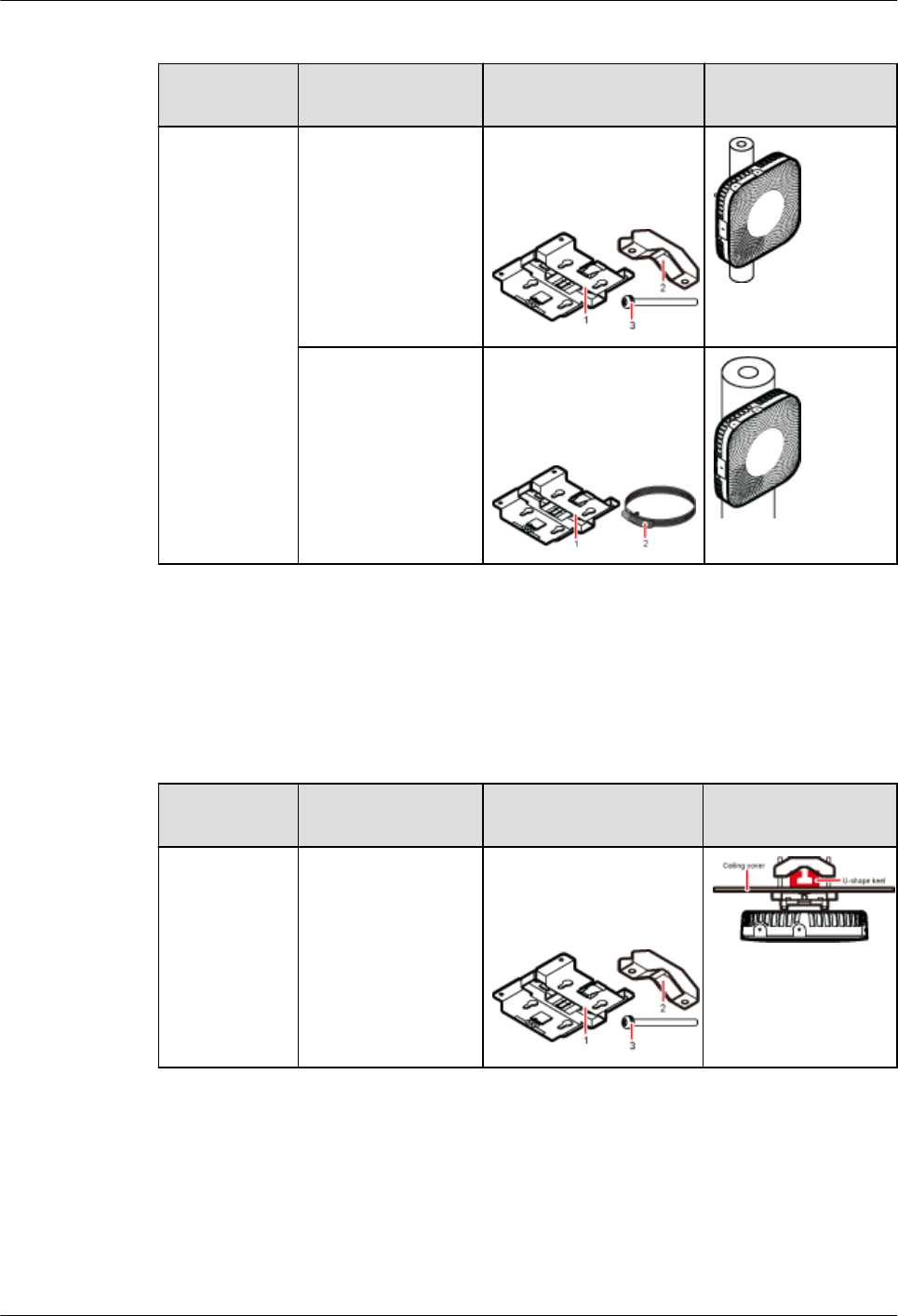
Table 7-4 Pole-mounted suggestion
Installation
Mode
Requirements Mounting Brackets Installation
Diagram
Installing the
pRRU3901 on
a pole
For details, see
7.4.4
Installing a
pRRU3901 on
a Pole.
The diameter of the
pole ranges from 30
mm to 70 mm.
1. Plate
2. V clamp
3. Bolt (M6X80)
The diameter of the
pole ranges from 70
mm to 110 mm.
1. Plate
2. Hose clamp, which is
prepared by the
customer
Installing the pRRU3901 on a keel
The pRRU3901 can be installed on a keel of U-shape, T-shape, or H-shape. For the keels of
other shapes, they are determined based on the onsite requirements.
Table 7-5 Keel-mounted installation suggestion
Installation
Mode
Requirements Mounting Brackets Installation
Diagram
Installing the
pRRU3901 on
a keel
For details, see
7.4.6
Installing a
pRRU3901 on
a Keel.
The keel is in U-
shape, T-shape, H-
shape, or other
shapes.
1. Plate
2. V clamp
3. Bolt (M6X80)
shows the pRRU
installed on a U-
shaped keel.
pRRU3901 cabinet
In the outdoor scenario, pRRU3901 should be installed in the cabinet.
DBS3900 LampSite
Installation Guide 7 Installing a pRRU3901
Issue 07 (2015-12-30) Huawei Proprietary and Confidential
Copyright © Huawei Technologies Co., Ltd.
58
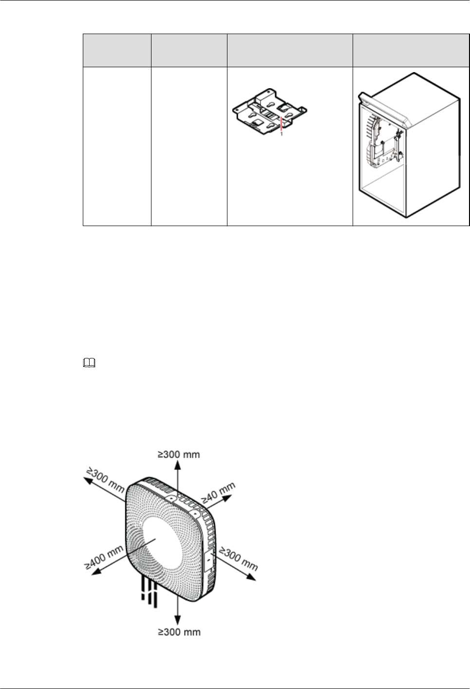
Table 7-6 Cabinet installation suggestion
Installation
Mode
Requirement
s
Mounting Brackets Installation Diagram
Installing the
cabinet
For details,
see7.4.7
Installing the
Cabinet
Remove the
housing before
installing a
pRRU3901 in
the cabinet.
1. Plate
7.1.3 Space Requirements
This chapter describes the space requirements of the pRRU3901.
When the pRRU3901 is installed on a wall, ceiling, pole or keel, the minimum space is
required for easy cabling and O&M. Based on the engineering practice, the recommendation
for the installation space is provided.
NOTE
During installation, a minimum clearance of 2 m must be reserved between the pRRU3901 working on
the 2.6 GHz band and the Wi-Fi module if they need to process services concurrently.
Figure 7-1 shows the recommended space requirements of the pRRU3901.
Figure 7-1 Recommended space requirements of the pRRU3901
The recommended space for installing a single pRRU3901 is described as follows:
DBS3900 LampSite
Installation Guide 7 Installing a pRRU3901
Issue 07 (2015-12-30) Huawei Proprietary and Confidential
Copyright © Huawei Technologies Co., Ltd.
59
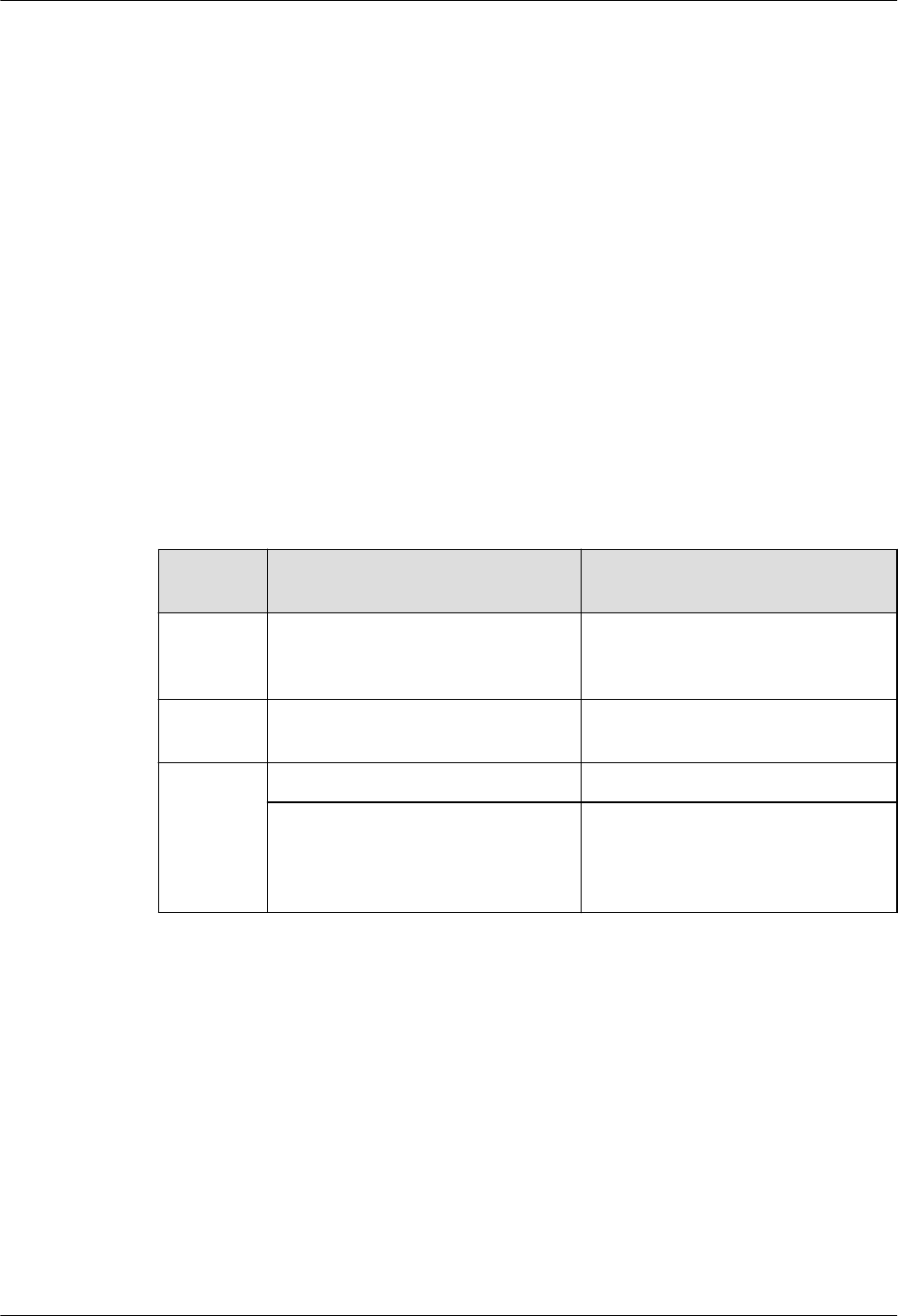
lAt least 300 mm above the pRRU3901 is reserved for maintenance.
lAt least 300 mm under the pRRU3901 is reserved for cabling.
lAt least 300 mm on the left of the pRRU3901 is reserved for maintenance.
lAt least 300 mm on the right of the pRRU3901 is reserved for maintenance.
lAt least 400 mm in front of the pRRU3901 is reserved for maintenance
lAt least 40 mm on the back of the pRRU3901 is reserved for ventilation.
In the outdoor scenario, there is no space requirement for the pRRU3901 installing in the
cabinet.
7.1.4 Installation Environment Requirements
The installation environment of a pRRU3901 involves the running environment specifications
for the pRRU3901 and other specifications.
Running Environment Specifications
Table 7-7 shows the environment specifications for the pRRU3901 installed indoors.
Table 7-7 pRRU3901 environment specifications
Specificat
ions
Condition Remarks
Operating
temperatur
e
lIndoor: - 5 °C to + 40 °C
lOutdoor: - 20 °C to + 40 °C
-
Relative
humidity
5% RH to 95% RH -
Altitude - 60 m to + 1800 m Works properly.
1800 m to 4000 m Above the 1800 m altitude, the
maximum operating temperature
decreases by 1 °C each time the
altitude increases by 220 m.
Other Running Environment Specifications
lThe pRRU3901 cannot be installed at an air outlet of the heat dissipation box of an air
conditioner or other heat-generating appliances.
lThe pRRU3901 cannot be installed near a strong heat source.
lThe pRRU3901 cannot be installed in a position with water dripping, such as outdoor
equipment of air conditioners, pipe, and leaking or dripping roofs.
lThe installation position must be far from rains. If the pRRU3901 is installed on a wall,
there must be no window on either side of the wall.
lThe installation position must be far away from high voltage, highly corrosive devices,
flammable or explosive substances, and electromagnetic interference such as power
stations, high-voltage substations, and wired TV towers.
DBS3900 LampSite
Installation Guide 7 Installing a pRRU3901
Issue 07 (2015-12-30) Huawei Proprietary and Confidential
Copyright © Huawei Technologies Co., Ltd.
60
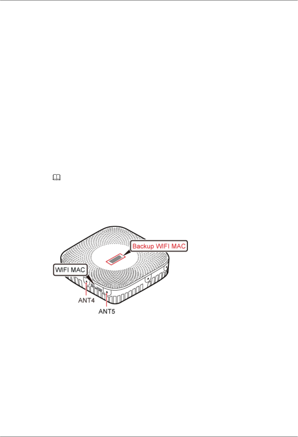
lThe pRRU3901 must be installed in a dry, ventilating, and dust-proof place.
lIf the pRRU3901 is installed in parking areas or basements, the installation position must
be well-ventilated.
7.2 Obtaining the MAC Address (Optional)
Before installing a pRRU3901, record the media access control (MAC) address, which will be
used during pRRU3901 commissioning. This section applies only when a pRRU3901 with
three transmission ports is configured with a Wi-Fi daughter board.
Context
The MAC address indicates the IP address through which a device can be reached.
Procedure
Step 1 Remove the backup WIFI MAC label from the front housing of the pRRU3901 and keep
them secure, as shown in Figure 7-2.
NOTE
lDo not remove the WIFI MAC label on the side of the pRRU3901 housing.
lBefore removing the backup WIFI MAC label, photograph it.
Figure 7-2 Removing backup WIFI MAC label
Step 2 Save the MAC according to 14.1 MAC Collection Template, and report it to the pRRU3901
commissioning personnel.
----End
7.3 Installation Process
This section describes the pRRU3901 installation process, which involves installing a
pRRU3901, and cables, checking the pRRU3901 hardware installation, and powering on the
pRRU3901.
Figure 7-3 shows the pRRU3901 installation process.
DBS3900 LampSite
Installation Guide 7 Installing a pRRU3901
Issue 07 (2015-12-30) Huawei Proprietary and Confidential
Copyright © Huawei Technologies Co., Ltd.
61
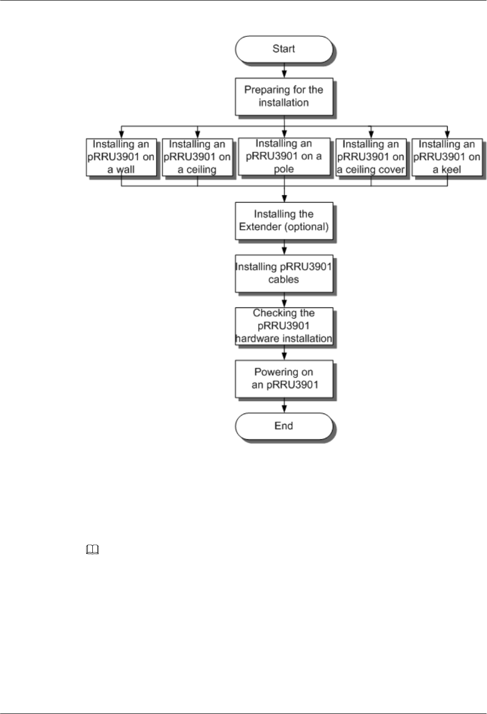
Figure 7-3 pRRU3901 installation process
7.4 Installing a pRRU3901
This section describes the pRRU3901 installation process. A pRRU3901 can be installed on a
wall, ceiling, indoor metal pole, or standard keel, but not on an aluminum panel or a non-
standard keel.
NOTE
Note the following when installing the pRRU3901:
lThe pRRU3901 cannot be grounded. If the pRRU3901 is grounded but the RHUB connected to this
pRRU3901 is not, the pRRU3901 may fail to be powered on.
lA minimum distance of 50 cm must be reserved between the pRRU3901 and the incandescent lamp.
lThe installation spacing between the pRRU3901 and the temperature sensor must be greater than 50
cm.
lIt is good practice to install the pRRU3901 on materials that can tolerate a temperature higher than
65°C and have an ignition point higher than 70°C.
DBS3900 LampSite
Installation Guide 7 Installing a pRRU3901
Issue 07 (2015-12-30) Huawei Proprietary and Confidential
Copyright © Huawei Technologies Co., Ltd.
62
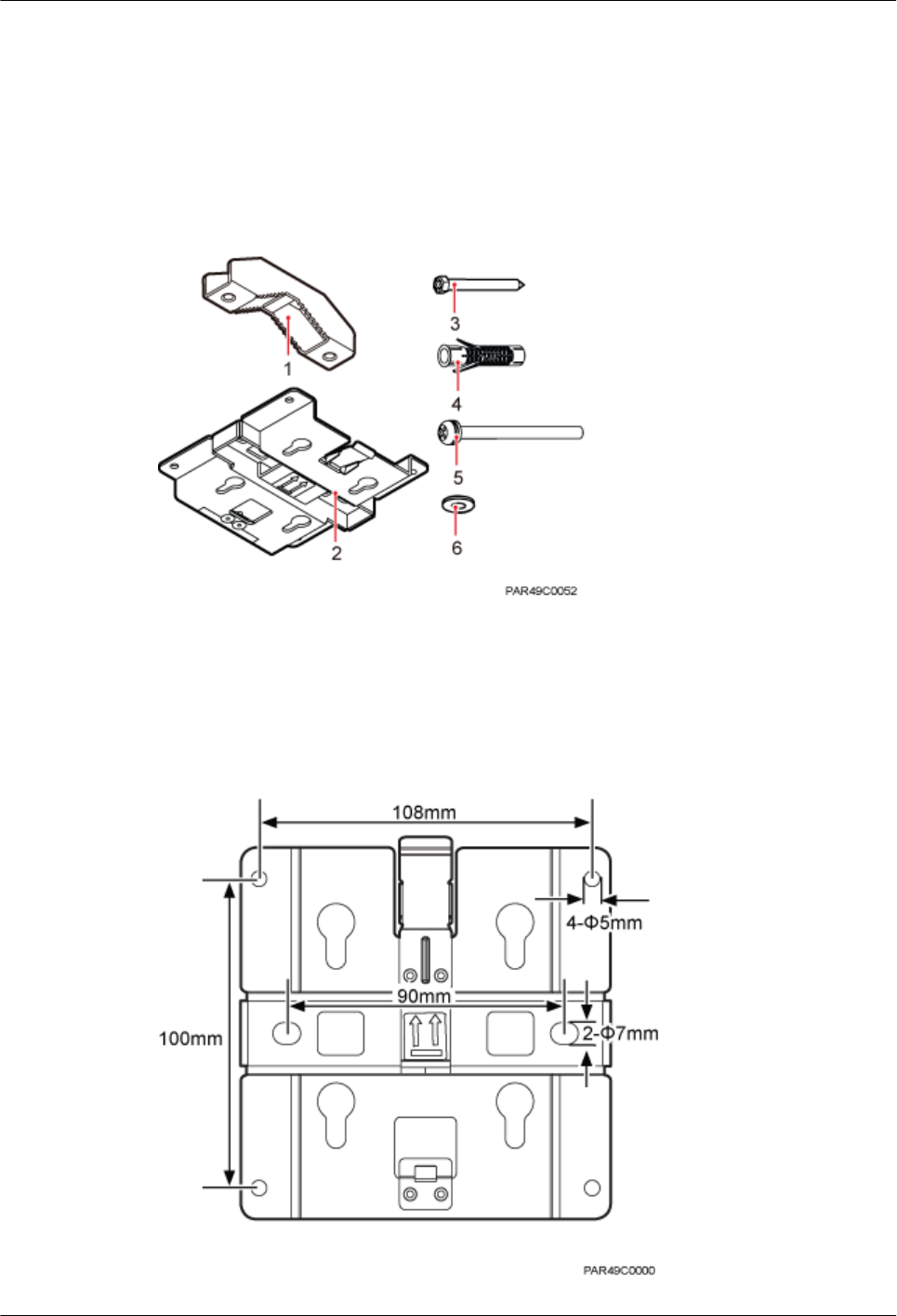
7.4.1 pRRU3901 Mounting Kits
This section describes the pRRU3901 mounting kits.
Figure 7-4 shows the exterior of the pRRU3901 mounting kits.
Figure 7-4 pRRU3901 mounting kits
(1) V clamp (2) Mounting bracket (3) Screw (M6x50)
(4) Plastic expansion sleeve (5) Bolt (M6x80) (6) Flat washer
The following figure shows the specifications of the mounting bracket.
Figure 7-5 Mounting bracket specifications
DBS3900 LampSite
Installation Guide 7 Installing a pRRU3901
Issue 07 (2015-12-30) Huawei Proprietary and Confidential
Copyright © Huawei Technologies Co., Ltd.
63
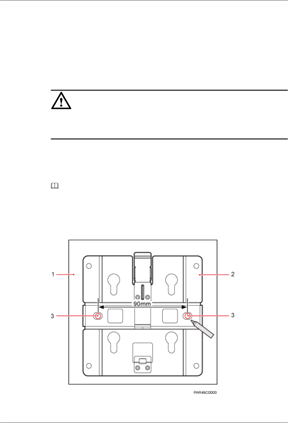
7.4.2 Installing a pRRU3901 on a Wall
This section describes how to install a pRRU3901 on an indoor wall. If a wall indoors has
adequate load bearing capacity and installation space, it is good practice to install the
pRRU3901 on the wall. If the wall does not have adequate load bearing capacity, choose an
installation mode based on site requirements.
Context
NOTICE
This section describes only the wall-mounted installation in which mounting kits are directly
installed on the wall without auxiliary devices. The procedure for other wall-mounted
installation modes is similar.
Procedure
Step 1 Determine the position for installing the pRRU3901 based on the construction blueprint and
the clearance requirements.
NOTE
For details about the clearance requirements, see 7.1.3 Space Requirements.
Step 2 Place the mounting bracket in the installation position against the wall. Then, level the
mounting bracket and use a marker to mark two anchor points. See Figure 7-6.
Figure 7-6 Anchor points on the pRRU3901 mounting bracket (unit: mm)
(1) Wall (2) Mounting bracket (3) Anchor point
DBS3900 LampSite
Installation Guide 7 Installing a pRRU3901
Issue 07 (2015-12-30) Huawei Proprietary and Confidential
Copyright © Huawei Technologies Co., Ltd.
64
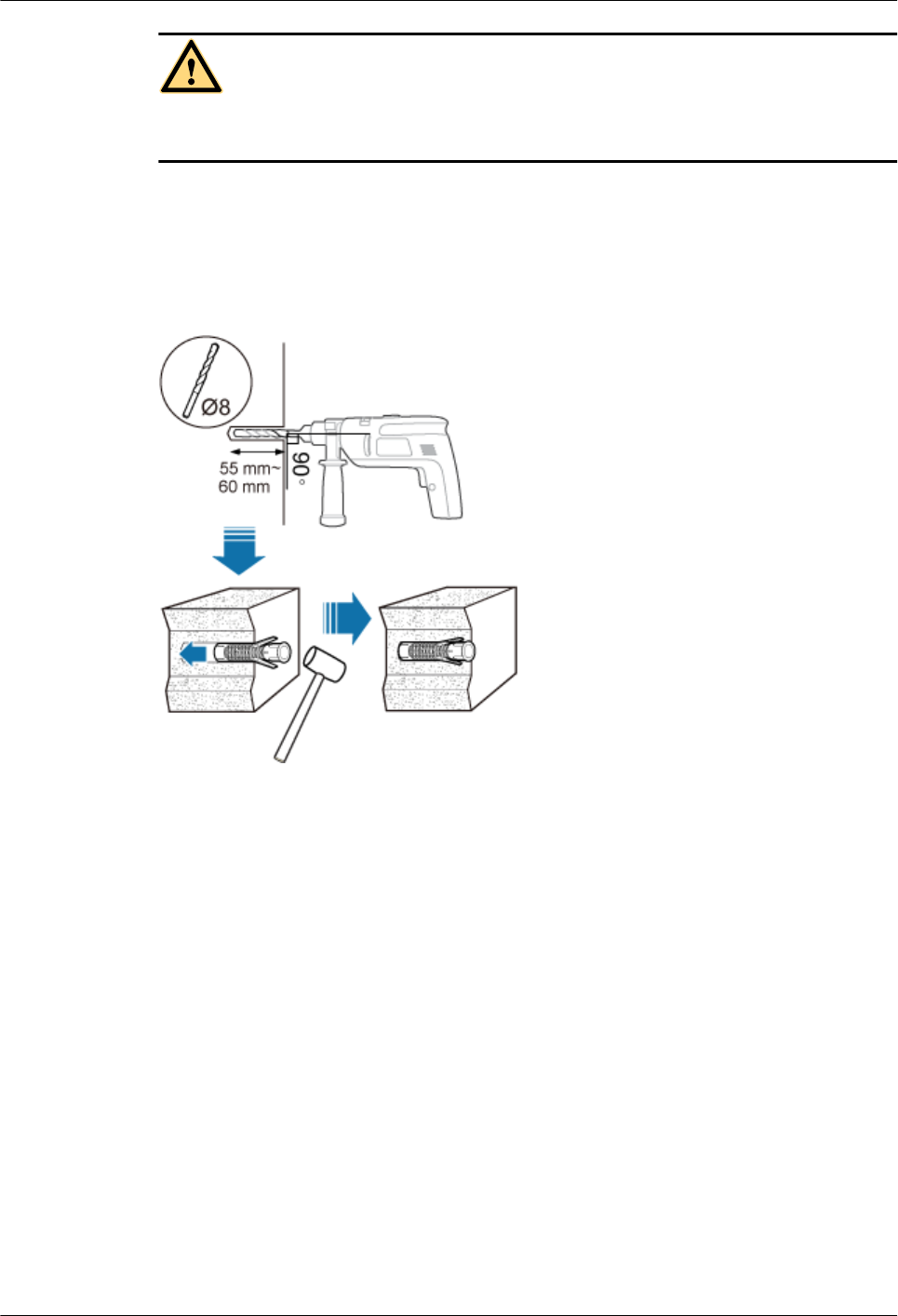
CAUTION
To prevent inhalation or eye contact with dust, take adequate preventive measures when
drilling holes.
Step 3 Use a hammer drill with φ8 bore to drill holes at the marked anchor points, as shown in
Figure 7-7. Use a vacuum cleaner to clean the dust inside and around the holes and measure
the distance between them. If they are inaccurately positioned, re-measure and re-drill the
holes. Then, use a rubber mallet to hit a plastic expansion sleeve into each hole.
Figure 7-7 Drilling holes and installing expansion bolts
Step 4 Lead the M6x50 screws through the washers, and then through the drilling holes on the
mounting bracket to the plastic expansion sleeves, and torque the screws to 5 N•m, as shown
in Figure 7-8.
DBS3900 LampSite
Installation Guide 7 Installing a pRRU3901
Issue 07 (2015-12-30) Huawei Proprietary and Confidential
Copyright © Huawei Technologies Co., Ltd.
65
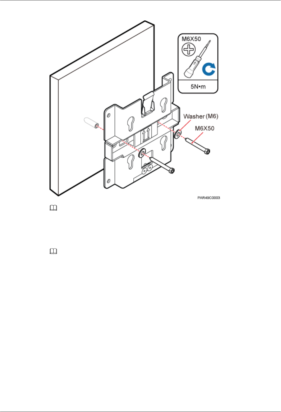
Figure 7-8 Installing the mounting bracket
NOTE
If the screws cannot be tightened using a Phillips screwdriver, use a hex key or an electric screwdriver to
assist the installation.
Step 5 Fit the four hooks of the pRRU3901 into the mounting holes on the mounting bracket and
then press the pRRU3901 downwards until a click is heard. See Figure 7-9.
NOTE
It is good practice to perform the installation from the side view to promptly align the hooks with the
mounting holes.
DBS3900 LampSite
Installation Guide 7 Installing a pRRU3901
Issue 07 (2015-12-30) Huawei Proprietary and Confidential
Copyright © Huawei Technologies Co., Ltd.
66
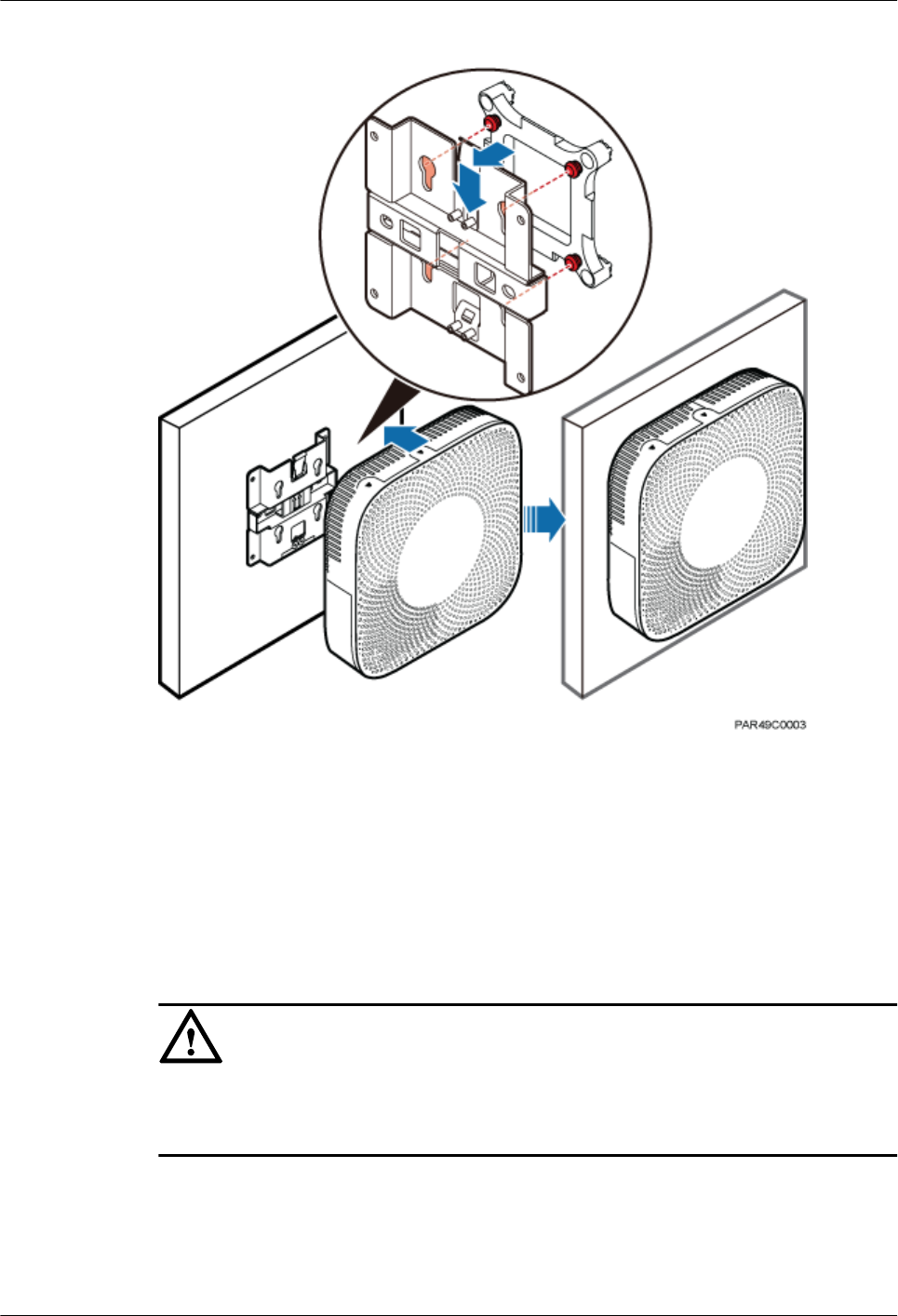
Figure 7-9 Installing the pRRU3901 on a wall
----End
7.4.3 Installing a pRRU3901 on a Ceiling
This section describes how to install a pRRU3901 on the ceiling, such as the concrete ceiling,
when the ceiling has adequate load bearing capacity and installation space.
Context
NOTICE
If the pRRU3901 is installed on a ceiling, the temperature of the ceiling may increase by a
maximum of 30 degrees. Therefore, whether a pRRU3901 can be installed on a ceiling
depends on the ceiling material.
Procedure
Step 1 Determine the position for installing the pRRU3901 based on the construction blueprint and
the clearance requirements.
DBS3900 LampSite
Installation Guide 7 Installing a pRRU3901
Issue 07 (2015-12-30) Huawei Proprietary and Confidential
Copyright © Huawei Technologies Co., Ltd.
67
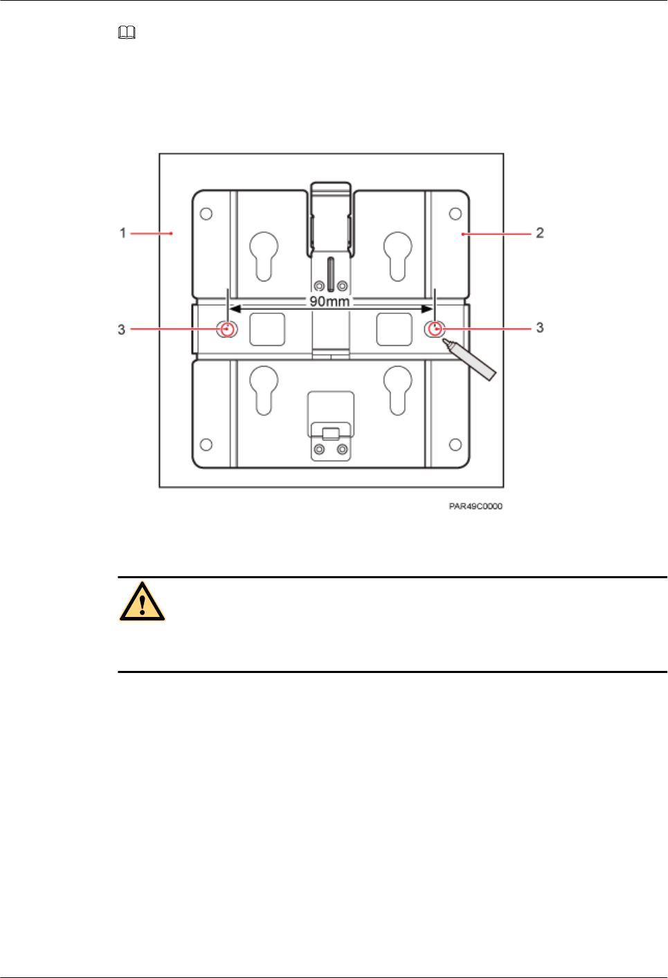
NOTE
For details about the clearance requirements, see 7.1.3 Space Requirements.
Step 2 Place the mounting bracket in the installation position against the ceiling. Then, level the
mounting bracket and use a marker to mark two anchor points. See Figure 7-10.
Figure 7-10 Anchor points on the pRRU3901 mounting bracket (unit: mm)
(1) Ceiling (2) Mounting bracket (3) Anchor point
CAUTION
To prevent inhalation or eye contact with dust, take adequate preventive measures when
drilling holes.
Step 3 Use a hammer drill with φ8 bore to drill holes at the marked anchor points, as shown in
Figure 7-11. Use a vacuum cleaner to clean the dust inside and around the holes and measure
the distance between them. If they are inaccurately positioned, re-measure and re-drill the
holes. Then, use a rubber mallet to hit a plastic expansion sleeve into each hole.
DBS3900 LampSite
Installation Guide 7 Installing a pRRU3901
Issue 07 (2015-12-30) Huawei Proprietary and Confidential
Copyright © Huawei Technologies Co., Ltd.
68
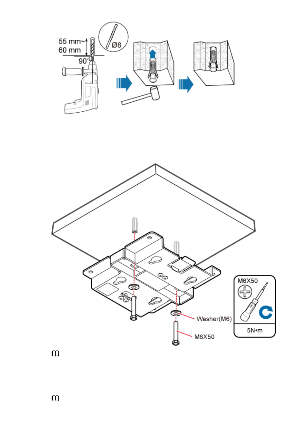
Figure 7-11 Drilling holes and installing expansion bolts
Step 4 Lead the M6x50 screws through the washers, and then through the drilling holes on the
mounting bracket to the plastic expansion sleeves, and use a torque screwdriver to torque the
screws to 5 N•m, as shown in Figure 7-12.
Figure 7-12 Installing the mounting bracket
NOTE
If the screws cannot be tightened using a Phillips screwdriver, use a hex key or an electric screwdriver to
assist the installation.
Step 5 Fit the four hooks of the pRRU3901 into the mounting holes on the mounting bracket and
then press the pRRU3901 downwards until a click is heard. See Figure 7-13.
NOTE
It is good practice to perform the installation from the side view to promptly align the hooks with the
mounting holes.
DBS3900 LampSite
Installation Guide 7 Installing a pRRU3901
Issue 07 (2015-12-30) Huawei Proprietary and Confidential
Copyright © Huawei Technologies Co., Ltd.
69
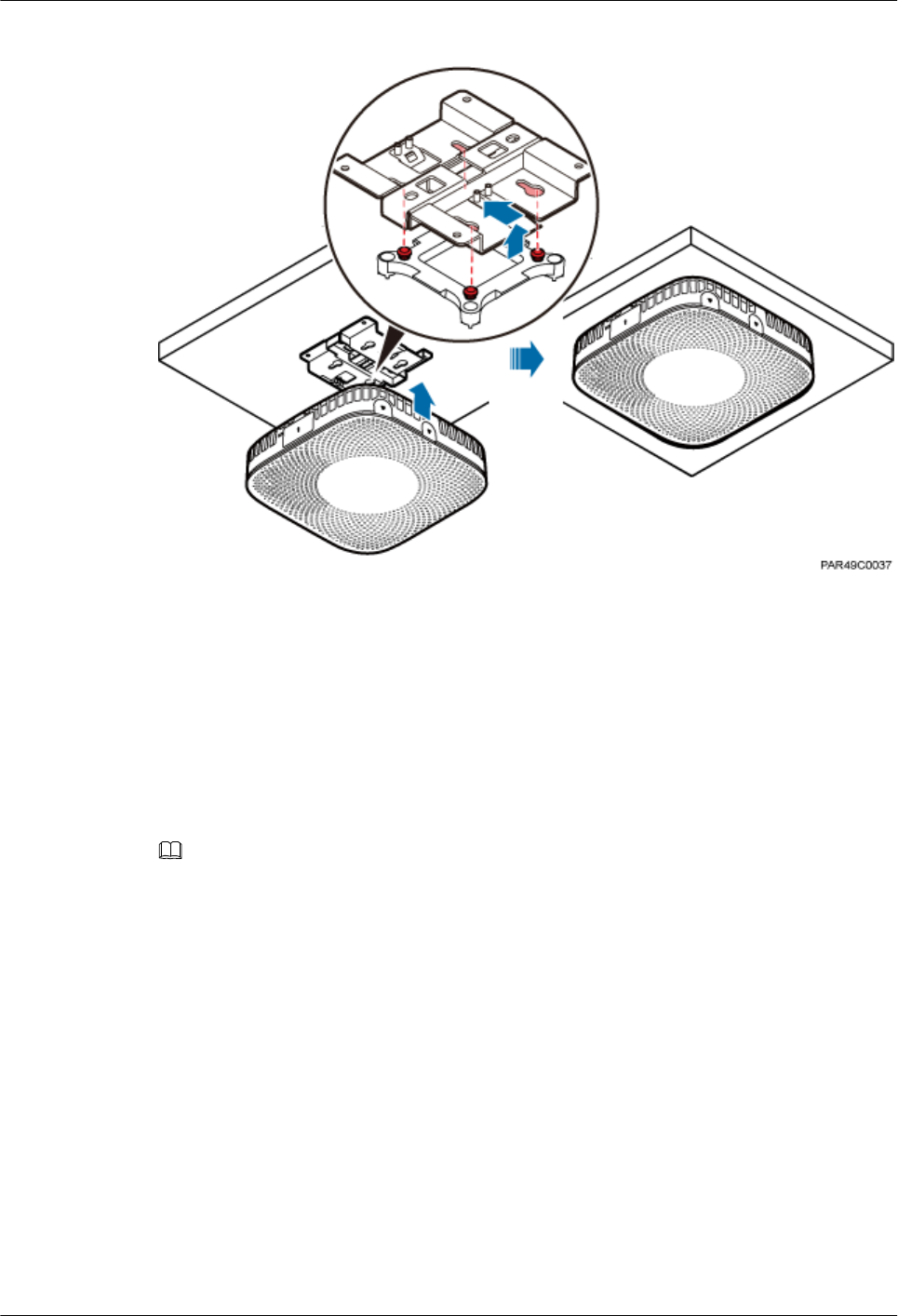
Figure 7-13 Installing a pRRU3901 on a ceiling
----End
7.4.4 Installing a pRRU3901 on a Pole
This section describes how to install a pRRU3901 on a metal pole indoors.
Procedure
Step 1 Determine the position for installing the pRRU3901 based on the construction blueprint and
the clearance requirements.
NOTE
For details about the clearance requirements, see 7.1.3 Space Requirements.
Step 2 If the diameter of the pole ranges from 30 mm to 70 mm, use the delivered V clamp,
mounting bracket, and bolts to install the pRRU3901 on the pole. Lead the M6x80 bolts
through the mounting bracket, and torque the bolts to 5 N•m, as shown in Figure 7-14.
DBS3900 LampSite
Installation Guide 7 Installing a pRRU3901
Issue 07 (2015-12-30) Huawei Proprietary and Confidential
Copyright © Huawei Technologies Co., Ltd.
70
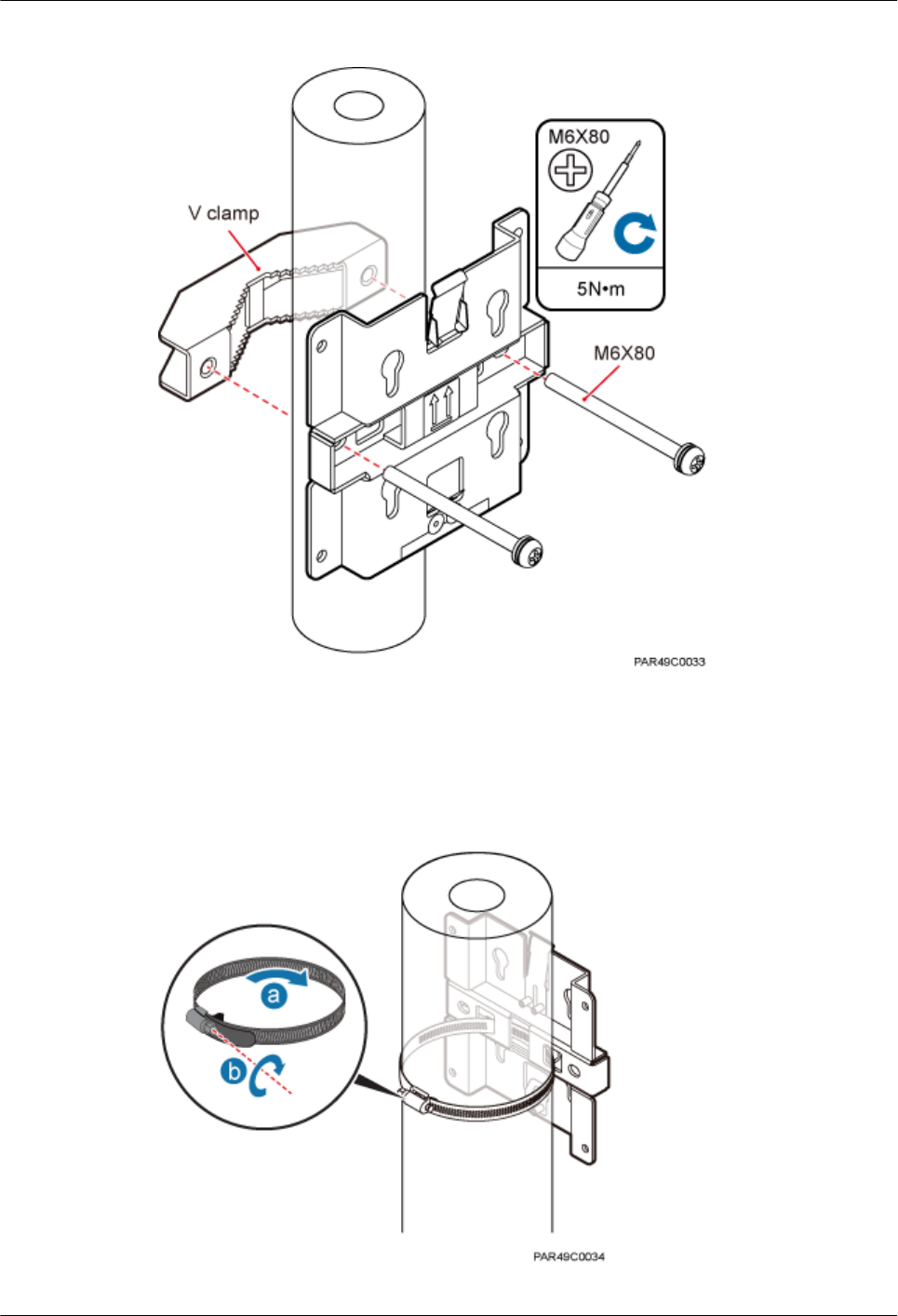
Figure 7-14 Securing the pRRU3901 mounting bracket on the metal pole
If the diameter of the pole is greater than 70 mm, use the hose clamp to install the mounting
bracket on the pole. The hose clamp is prepared by customers. Torque the bolts to 5 N•m, as
shown in Figure 7-15.
Figure 7-15 Securing the pRRU3901 mounting bracket on the metal pole
DBS3900 LampSite
Installation Guide 7 Installing a pRRU3901
Issue 07 (2015-12-30) Huawei Proprietary and Confidential
Copyright © Huawei Technologies Co., Ltd.
71
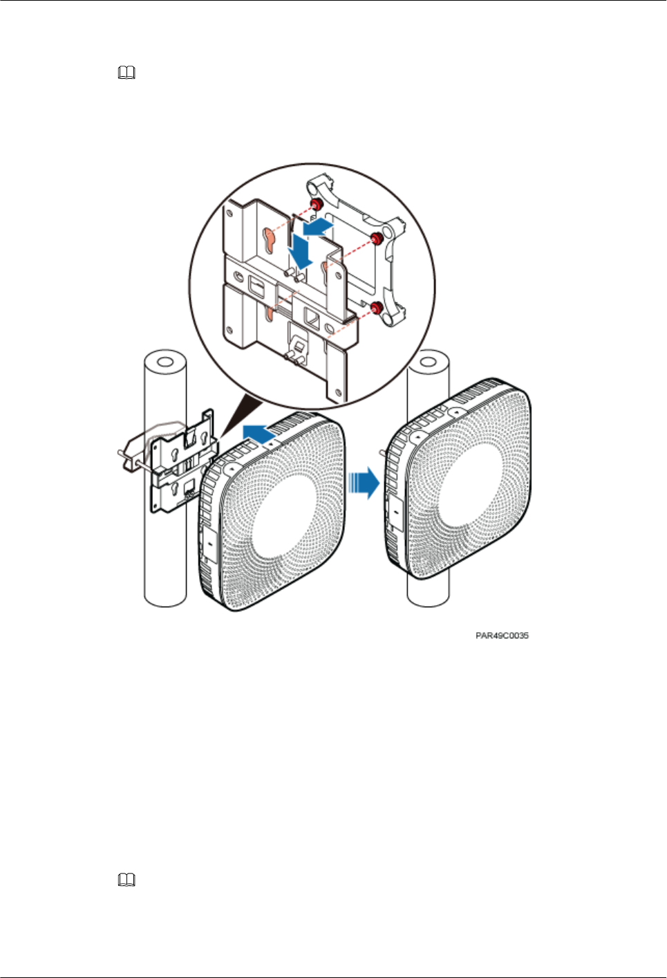
Step 3 Fit the four hooks of the pRRU3901 into the mounting holes on the mounting bracket and
then press the pRRU3901 downwards until a click is heard. See Figure 7-16.
NOTE
It is good practice to perform the installation from the side view to promptly align the hooks with the
mounting holes.
Figure 7-16 Installing a pRRU3901 on a pole
----End
7.4.5 Installing a pRRU3901 on a Plate
This section describes how to install a pRRU3901 on a plate. If a suspended ceiling plate has
adequate load bearing capacity and installation space, the pRRU3901 can be installed on the
plate. However, it is good practice not to install a pRRU3901 on an aluminum plate.
Procedure
Step 1 Determine the position for installing the pRRU3901 based on the construction blueprint and
the clearance requirements.
NOTE
For details about the clearance requirements, see 7.1.3 Space Requirements.
Step 2 Place the mounting bracket in the installation position against the wall. Then, level the
mounting bracket and use a marker to mark two anchor points. See Figure 7-17.
DBS3900 LampSite
Installation Guide 7 Installing a pRRU3901
Issue 07 (2015-12-30) Huawei Proprietary and Confidential
Copyright © Huawei Technologies Co., Ltd.
72
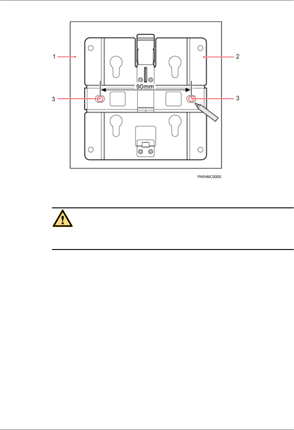
Figure 7-17 Anchor points on the pRRU3901 mounting bracket (unit: mm)
(1) Plate (2) Mounting bracket (3) Anchor point
CAUTION
To prevent inhalation or eye contact with dust, take adequate preventive measures when
drilling holes.
Step 3 Use a hammer drill with φ8 bore to drill holes at the anchor points.
Step 4 Lead the M6x80 bolts through the mounting bracket and the ceiling plate, and use a torque
screwdriver to torque the bolts to 5 N•m, as shown in Figure 7-18.
DBS3900 LampSite
Installation Guide 7 Installing a pRRU3901
Issue 07 (2015-12-30) Huawei Proprietary and Confidential
Copyright © Huawei Technologies Co., Ltd.
73
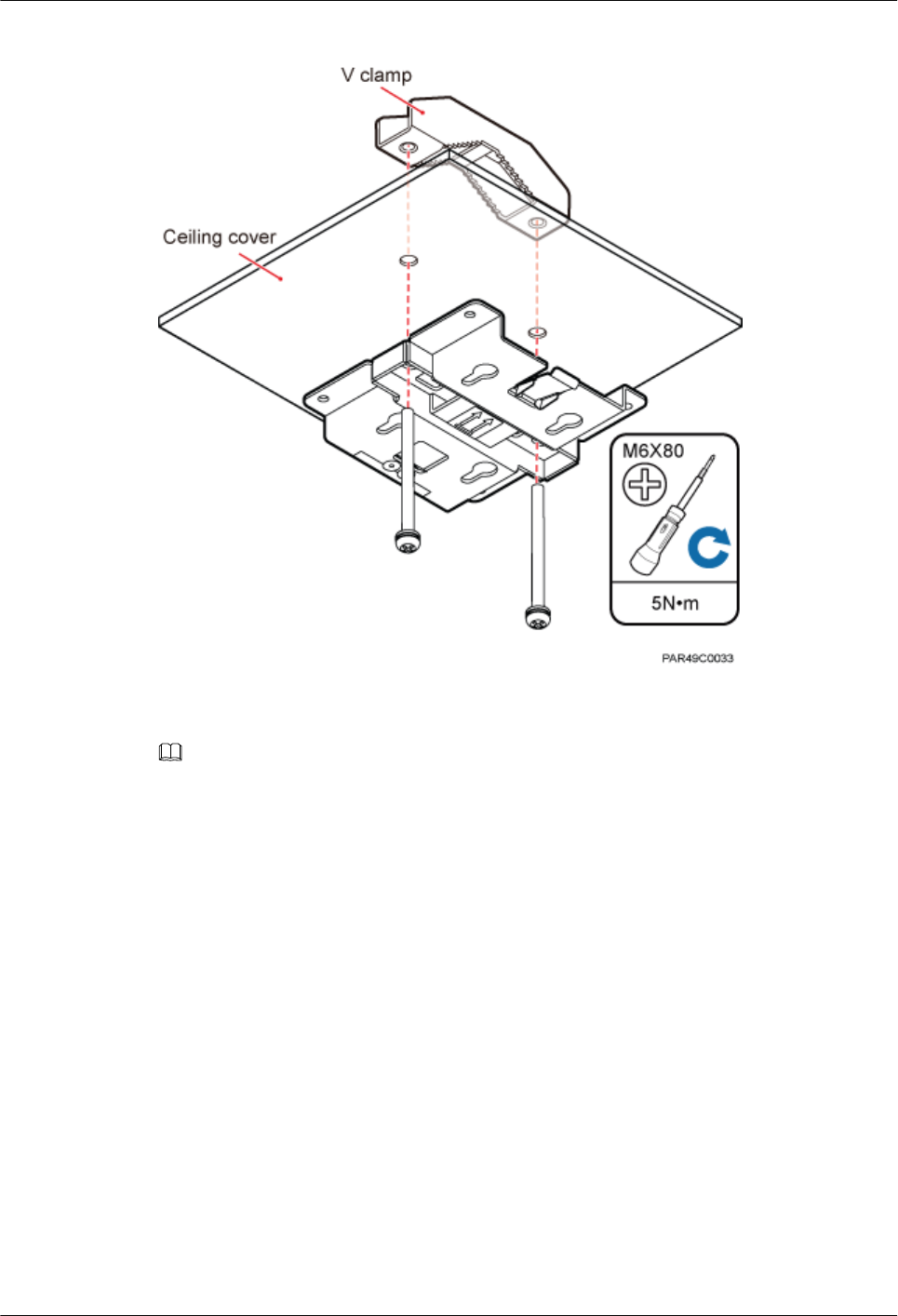
Figure 7-18 Installing the pRRU3901 mounting bracket
Step 5 Fit the four hooks of the pRRU3901 into the mounting holes on the mounting bracket and
then press the pRRU3901 downwards until a click is heard. See Figure 7-19.
NOTE
It is good practice to perform the installation from the side view to promptly align the hooks with the
mounting holes.
DBS3900 LampSite
Installation Guide 7 Installing a pRRU3901
Issue 07 (2015-12-30) Huawei Proprietary and Confidential
Copyright © Huawei Technologies Co., Ltd.
74
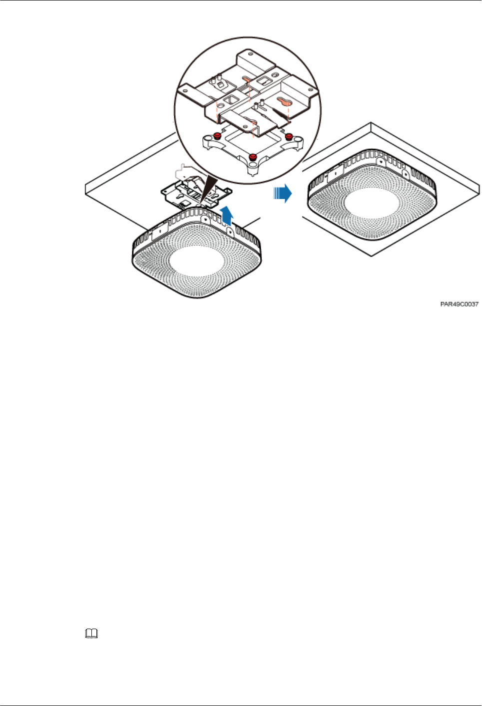
Figure 7-19 Installing a pRRU3901 on a plate
----End
7.4.6 Installing a pRRU3901 on a Keel
This section describes how to install a pRRU3901 on a keel. If a suspended ceiling plate
cannot bear the pRRU3901, the pRRU3901 can be installed on the keel on the ceiling.
Context
Before installing the pRRU3901 on a keel, ensure that the keel is strong enough to bear the
pRRU3901.
lThe mounting bracket of the pRRU3901 can be installed on the keel of the following
specifications: GBT 11981-2008, JIS A6517-2002, and ASTM C635 C635M-2007. The
installation mode depends on onsite requirements because there are various keels.
lThis section describes the procedure of installing a pRRU3901 on the keel of JIS
standard used in Japan. The procedure of installing a pRRU3901 on other keels is the
same as that of installing a pRRU3901 on the keel of JIS standard.
Procedure
Step 1 Determine the position for installing the pRRU3901 based on the construction blueprint and
the clearance requirements.
NOTE
For details about the clearance requirements, see 7.1.3 Space Requirements.
Step 2 Place the V clamp across the keel, and use a marker to mark the projective positions of the
mounting holes on the suspended ceiling plate, as shown in Figure 7-20.
DBS3900 LampSite
Installation Guide 7 Installing a pRRU3901
Issue 07 (2015-12-30) Huawei Proprietary and Confidential
Copyright © Huawei Technologies Co., Ltd.
75
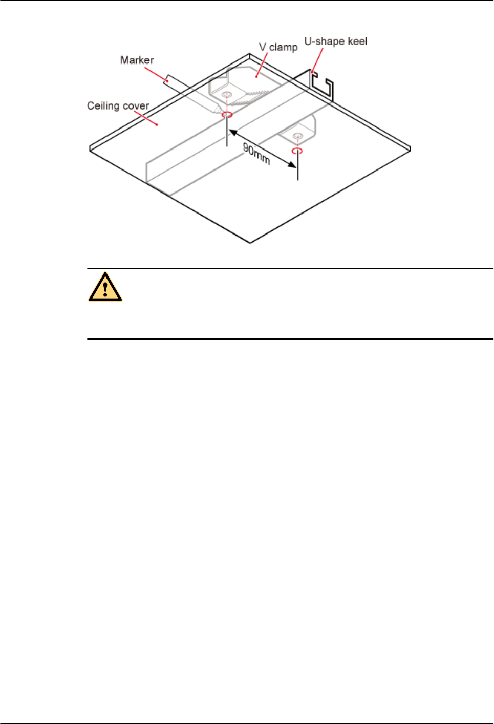
Figure 7-20 Anchor points on the suspended ceiling plate (unit: mm)
CAUTION
To prevent inhalation or eye contact with dust, take adequate preventive measures when
drilling holes.
Step 3 Use a hammer drill to drill holes at the anchor points. You are advised to use the hammer drill
with Ф12 bore.
Step 4 Lead the M6x80 bolts through the mounting bracket and the suspended ceiling plate. Use a
torque screwdriver to torque the bolts to 5 N•m, as shown in Figure 7-21.
DBS3900 LampSite
Installation Guide 7 Installing a pRRU3901
Issue 07 (2015-12-30) Huawei Proprietary and Confidential
Copyright © Huawei Technologies Co., Ltd.
76
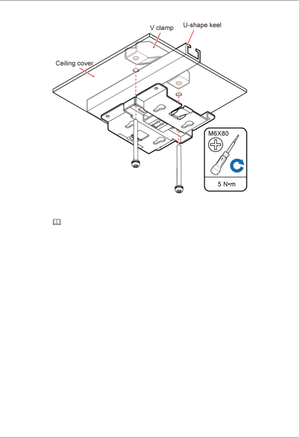
Figure 7-21 Installing the pRRU3901 mounting bracket
Step 5 Fit the four hooks of the pRRU3901 into the mounting holes on the mounting bracket and
then press the pRRU3901 downwards until a click is heard. See Figure 7-22.
NOTE
It is good practice to perform the installation from the side view to promptly align the hooks with the
mounting holes.
DBS3900 LampSite
Installation Guide 7 Installing a pRRU3901
Issue 07 (2015-12-30) Huawei Proprietary and Confidential
Copyright © Huawei Technologies Co., Ltd.
77
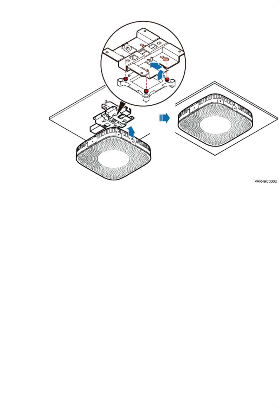
Figure 7-22 Installing a pRRU3901 on a keel
----End
7.4.7 Installing the Cabinet
In the outdoor scenario, the pRRU3901 should be installed in the cabinet firstly.
Context
lWhen installed in the cabinet, the housing of pRRU3901 should be removed.
lAn RF surge protector provides surge protection for the RF ports on pRRU3902, and a
PoE surge protector provides surge protection for the CPRI ports.
lOne pRRU3901 with internal antenna need to be configured with one or two PoE surge
protectors.
lOne pRRU3901 with external antenna need to be configured with one PoE surge
protector, or two RF surge protectors when one RF daughter board is configured, or four
RF surge protectors when two RF daughter boards are configured.
Procedure
Step 1 Remove the housing on the top and at the bottom of pRRU3901, as shown in Figure 7-23.
DBS3900 LampSite
Installation Guide 7 Installing a pRRU3901
Issue 07 (2015-12-30) Huawei Proprietary and Confidential
Copyright © Huawei Technologies Co., Ltd.
78
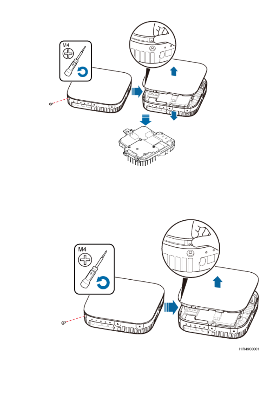
Figure 7-23 Removing the housing of pRRU3901
1. Use the M4 Phillips screwdriver to loosen the Phillips screw on the pRRU housing.
Wrench and remove the housing from the installation position of the Phillips screw hole,
as shown in Figure 7-24.
Figure 7-24 Removing the pRRU housing
DBS3900 LampSite
Installation Guide 7 Installing a pRRU3901
Issue 07 (2015-12-30) Huawei Proprietary and Confidential
Copyright © Huawei Technologies Co., Ltd.
79
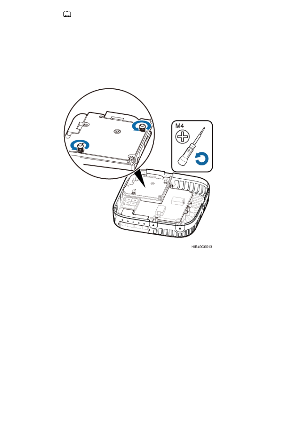
NOTE
– The pRRU housing and the RF daughter board can be secured using either Phillips screws or
protection screws, requiring the same installation operations. This section uses Phillips screws
as an example to describe the installation operations.
– Keep the Phillips screw secure for future use.
2. Use the M4 Phillips screwdriver to loosen the Phillips screws on the RF daughter board,
as shown in Figure 7-25.
Figure 7-25 Loosen the Phillips screws
3. Use the left hand to hold the RF daughter board and the right hand to hold the right
handle of the RF daughter board to remove the RF daughter board and put it into an ESD
box or bag, as shown in Figure 7-26.
DBS3900 LampSite
Installation Guide 7 Installing a pRRU3901
Issue 07 (2015-12-30) Huawei Proprietary and Confidential
Copyright © Huawei Technologies Co., Ltd.
80
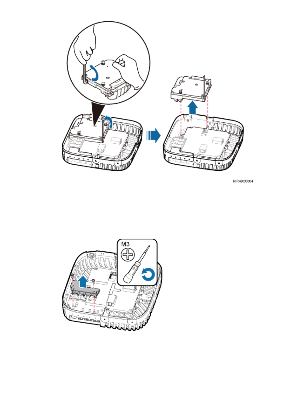
Figure 7-26 Removing the RF daughter board in slot1
4. Use an M3 Phillips screwdriver to loosen the two fastening screws of the light pipe, and
remove the light pipe, as shown in Figure 7-27.
Figure 7-27 Removing the light pipe
5. Use the M3 Phillips screwdriver to loosen the four fastening screws of the pDock mother
board, and remove the pDock mother board, as shown in Figure 7-28.
DBS3900 LampSite
Installation Guide 7 Installing a pRRU3901
Issue 07 (2015-12-30) Huawei Proprietary and Confidential
Copyright © Huawei Technologies Co., Ltd.
81
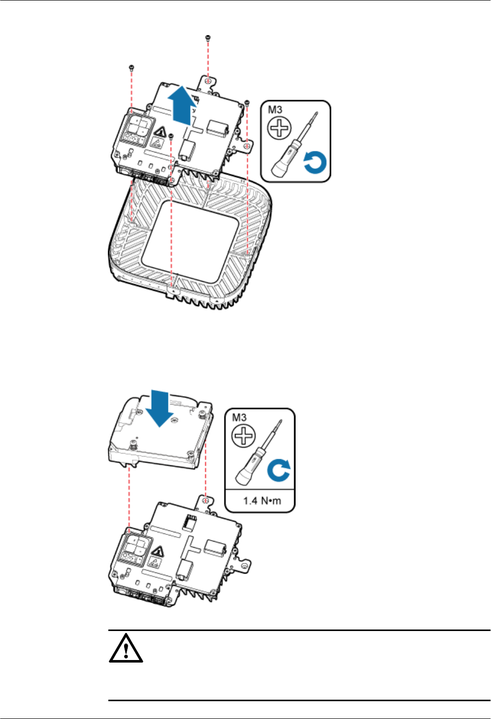
Figure 7-28 Removing the pDock mother board
6. Install the RF daughter boards in slots S1, and use the M4 Phillips screwdriver to tighten
the two fastening screws always carried on each daughter board to 1.4 N•m, as shown in
Figure 7-29.
Figure 7-29 Installing the RF daughter boards
NOTICE
The installation positions of the RF daughter boards must be consistent before and after
the replacement.
DBS3900 LampSite
Installation Guide 7 Installing a pRRU3901
Issue 07 (2015-12-30) Huawei Proprietary and Confidential
Copyright © Huawei Technologies Co., Ltd.
82
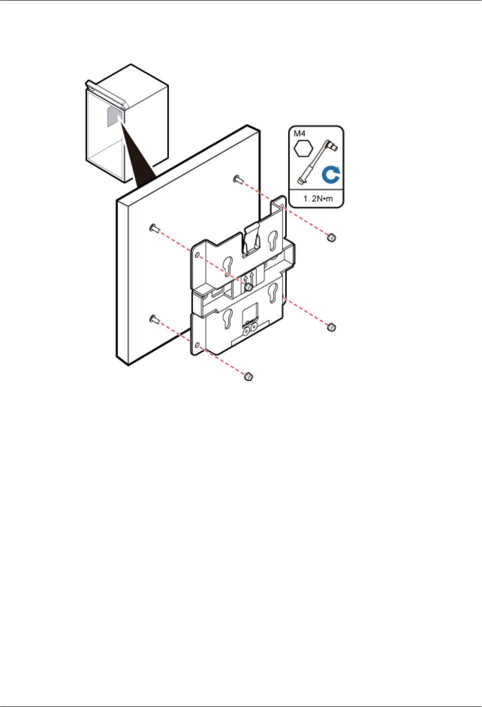
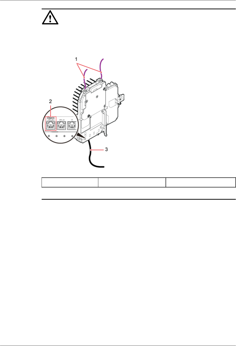
NOTICE
Make sure all the cables are installed before installing the plate. For details about installing
the cables of pRRU3901, see Figure 7-31.
Figure 7-31 Installing the pRRU3901 cables
(1) RF Jumper (2) CPRI_E0 port (3) Ethernet Cable
Step 3 Fit the four hooks on pRRU3901 into the hooks on the mounting bracket, and then push
pRRU3901 down against the mounting bracket until a click is heard, as shown in Figure
7-32.
DBS3900 LampSite
Installation Guide 7 Installing a pRRU3901
Issue 07 (2015-12-30) Huawei Proprietary and Confidential
Copyright © Huawei Technologies Co., Ltd.
84
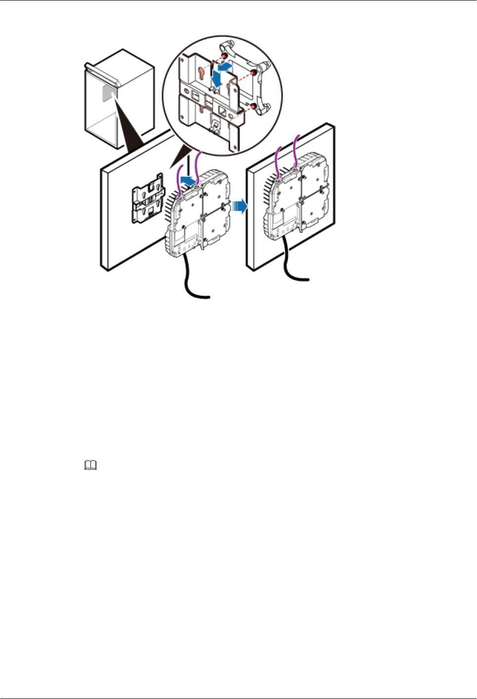
Figure 7-32 Installing a pRRU3901 into the cabinet
----End
7.5 Installing pRRU3901 Cables
This section describes the procedure of installing the pRRU3901 cables.
7.5.1 Requirements for Cable Layout
Cables must be routed according to the specified cabling requirements to prevent signal
interference.
NOTE
If certain cables listed below are not required, skip the requirements for routing these cables.
General Requirements for Cable Layout
National Standards
lCode for Engineering Design of Generic Cabling System for Building and Campus (GB
50311-2007)
lCode for Engineering Acceptance of Generic Cabling System for Building and Campus
(GB50312-2007).
lSecurity Protection Engineering Technology Specifications (GB 50348-2004)
lCode for Construction and Acceptance of the Electronic Information System Room (GB
50462-2008)
lCode for Quality Acceptance of the Intelligent Building Engineering (GB 50339-2003)
lCode for Quality Acceptance of Electric Engineering Construction in Building (GB
50303-2002)
DBS3900 LampSite
Installation Guide 7 Installing a pRRU3901
Issue 07 (2015-12-30) Huawei Proprietary and Confidential
Copyright © Huawei Technologies Co., Ltd.
85

lTechnical Specification for Construction and Acceptance of Telecommunication Conduit
Engineering (GB 50374-2006)
International Standards
lGeneric Cabling for Customer Premises (ISO/IEC 11801)
lCommercial Building Telecommunications Cabling Standard (EIA/TIA 568)
lCommercial Building Standard for Telecommunication Pathways and Spaces (EIA/TIA
569)
lAdministration Standard for Commercial Telecommunications Infrastructure (EIA/TIA
606)
lGrounding and Bonding Requirements for Telecommunications in Commercial
Buildings (EIA/TIA 607)
lGeneric Cabling Systems for Information Technology (EN 50173)
lCabling Installation for Information Technology (EN 50174)
Bending radius
lThe bending radius of a 1/4'' jumper, a 1/2'' softer jumper, and a 1/2'' common jumper
must be longer than 35 mm, 50 mm, and 127 mm, respectively.
lThe bending radius of a power cable is at least three times the diameter of the cable.
lThe bending radius of a signal cable must be at least five times of the diameter of the
cable.
Cable binding
lCables of the same type are bound together.
lDifferent types of cables must be separately routed with a minimum spacing of 30 mm
and cannot be entangled.
lThe cables are bound tightly and neatly and the sheaths of the cables is intact.
lThe cable ties face the same direction and all cable ties bound at similar positions must
be in a straight line.
lThe extra length of each indoor cable tie must be cut off. A slack of 5 mm is reserved for
each outdoor cable tie before the extra length is cut off. All cut surfaces are without
sharp edges.
lLabels or nameplates are attached to both ends, joints, or turns of cables after they are
installed.
Safety
lThe steel pipe or fire-resistant rigid polyvinyl chloride pipe should be used for the cable
duct or for routing cables. The cross-sectional usage of the cable duct should be 30% to
50% and that of the pipe for routing cables should be 25% to 30%.
lCables are placed away from sharp objects or wall burrs. If these positions are inevitable,
protection pipes are required for the cables.
lCables are routed away from heat sources, or heat-insulation materials are added
between cables and heat sources.
lA clearance is reserved at turns of a cable or the position close to a device, facilitating
cable and device maintenance. The recommended clearance is about 0.1 m.
Requirements for Special Cables
Ethernet Cable
DBS3900 LampSite
Installation Guide 7 Installing a pRRU3901
Issue 07 (2015-12-30) Huawei Proprietary and Confidential
Copyright © Huawei Technologies Co., Ltd.
86

lA maximum of 100 Ethernet cables can be bundled if no PVC pipes are used. If pipes are
used, a maximum of 24 Ethernet cables can be led through a pipe. In this case, ensure
that 1/3 space inside the pipes must be vacant.
lThe point at which an Ethernet cable is bundled must be spaced 400 mm or less from the
Ethernet port on a pRRU.
lFor the pRRU3901 used in the elevator engine room on the rooftop, generator set for the
subway engine, and equipment room with central air conditioning, Ethernet cables must
be led through metallic conduits that are reliably grounded at both ends.
7.5.2 pRRU3901 Cable List
This section describes pRRU3901 cable connections.
Table 7-8 lists pRRU3901 cables.
Table 7-8 List of pRRU3901 cables
Cable One End The Other End
Connector Connected
to ...
Connector Connected to ...
Ethernet
Cable
RJ45 connector CPRI_E0~CP
RI_E7 port on
RHUB
RJ45 connector CPRI_E0~CPRI_
E1 port on
pRRU3901
RJ45 connector Transmission
port on Access
Control(AC)
RJ45 connector GE port on
pRRU3901
RJ45 connector CPRI_E0~CP
RI_E7 port on
RHUB
RJ45 connector Protect port on
PoE surge
protector 2
RJ45 connector Surge port on
PoE surge
protector 2
RJ45 connector Surge port on
PoE surge
protector 1
RJ45 connector Protect port on
PoE surge
protector 1
RJ45 connector CPRI_E0~CPRI_
E1 port on
pRRU3901
(Optional)
RF Jumper
SMA straight
male connector
External
antenna
TX/RX RF
port on
pRRU3901
Based on the
port model of
the antenna
system.
Antenna system
SMA straight
male connector
External
antenna
TX/RX RF
port on
pRRU3901
SMA straight
male connector
Protect port on
RF surge
protector
DBS3900 LampSite
Installation Guide 7 Installing a pRRU3901
Issue 07 (2015-12-30) Huawei Proprietary and Confidential
Copyright © Huawei Technologies Co., Ltd.
87

Cable One End The Other End
Connector Connected
to ...
Connector Connected to ...
SMA straight
male connector
Surge port on
RF surge
protector
Based on the
port model of
the antenna
system.
Antenna system
NOTE
When the RHUB and the pRRU3901 connected using the Ethernet cable. If the Extender is used,
lIn the indoor scenario, the Ethernet cable is divided into two parts, one between the RHUB and the
Extender and the other between the Extender and the pRRU3901.
lIn the outdoor scenario, the Ethernet cable is divided into two parts, one among RHUB-PoE surge
protector 2- PoE surge protector 3-Extender and the other among the Extender- PoE surge
protector 4- PoE surge protector 1-pRRU3901.
7.5.3 Cable Connections (Indoor)
This section describes the cable connections for a single pRRU3901 and multiple pRRU3901s
in UMTS, LTE FDD, UMTS+LTE FDD, LTE FDD+LTE FDD mode.
Before installing the pRRU3901 cables, you must be aware of the following information:
lThe pRRU3901 can obtain power supply through the power over Ethernet (PoE).
lFor external antennas corresponding to RF daughter board 1, the TX port and RX port
are ANT0 and ANT1, respectively. For external antennas corresponding to RF daughter
board 2, the TX port and RX port are ANT2 and ANT3, respectively. For external
antennas corresponding to RF daughter board 3, the TX port and RX port are ANT4 and
ANT5, respectively.
lThe external antenna system is optional, and the pRRU3901 jumpers are not delivered.
By default, the pRRU3901s are configured with built-in antennas. If the external antenna
system is connected, the antenna system automatically switches to the external one. One
end of the pRRU3901 RF jumper is the SMA male connector, which is connected to the
external antenna TX/RX RF port on the pRRU3901. The other end of the pRRU3901 RF
jumper is the type N male connector, which is connected to the antenna system. For the
standard of the pRRU3901 RF jumper, see (Optional) RF Jumper of the DBS3900
LampSite Hardware Description.
Figure 7-33 shows the cable connection when the pRRU3901 is configured with only one RF
Daughter Board.
DBS3900 LampSite
Installation Guide 7 Installing a pRRU3901
Issue 07 (2015-12-30) Huawei Proprietary and Confidential
Copyright © Huawei Technologies Co., Ltd.
88
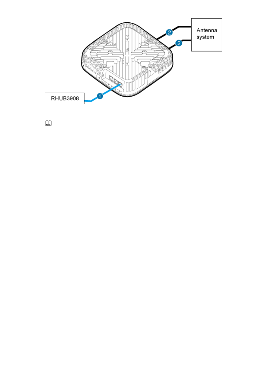
Figure 7-33 pRRU3901 cable connection (1)
(1) Ethernet cable (2) RF jumper
NOTE
lThe Extender can be used to lengthen the distance between the RHUB and the pRRU3901 connected
using the Ethernet cable. If the Extender is used, the Ethernet cable is divided into two parts, one
between the RHUB and the Extender and the other between the Extender and the pRRU3901.
lWhen two Ethernet cables are used to transmit CPRI signals, connect one end of the cables to the
CPRI_E0 and CPRI_E1 ports on the pRRU panel and the other end to any two ports of CPRI_E0 to
CPRI_E7 on the RHUB panel. On the RHUB panel, CPRI_E0 and CPRI_E1, CPRI_E2 and
CPRI_E3, CPRI_E4 and CPRI_E5, and CPRI_E6 and CPRI_E7 are used in pairs. CPRI_E0 on the
pRRU panel connects to the even-numbered CPRI port (for example, CPRI_E0, CPRI_E2,
CPRI_E4, or CPRI_E6) on the RHUB panel, and CPRI_E1 on the pRRU panel connects to the odd-
numbered CPRI port (for example, CPRI_E1, CPRI_E3, CPRI_E5, or CPRI_E7). This document
describes signal transmission using one Ethernet cable as an example.
Figure 7-34 shows the cable connection when the pRRU3901 is configured with two RF
Daughter Boards.
DBS3900 LampSite
Installation Guide 7 Installing a pRRU3901
Issue 07 (2015-12-30) Huawei Proprietary and Confidential
Copyright © Huawei Technologies Co., Ltd.
89
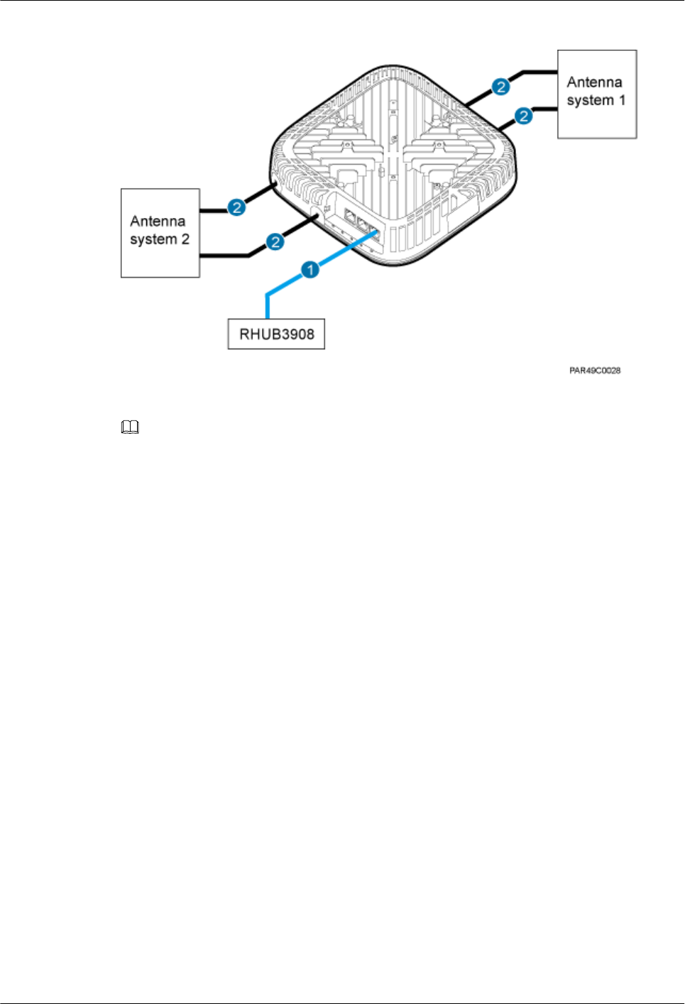
Figure 7-34 pRRU3901 cable connection (2)
(1) Ethernet cable (2) RF jumper
NOTE
lThe Extender can be used to lengthen the distance between the RHUB and the pRRU3901 connected
using the Ethernet cable. If the Extender is used, the Ethernet cable is divided into two parts, one
between the RHUB and the Extender and the other between the Extender and the pRRU3901.
lWhen two Ethernet cables are used to transmit CPRI signals, connect one end of the cables to the
CPRI_E0 and CPRI_E1 ports on the pRRU panel and the other end to any two ports of CPRI_E0 to
CPRI_E7 on the RHUB panel. On the RHUB panel, CPRI_E0 and CPRI_E1, CPRI_E2 and
CPRI_E3, CPRI_E4 and CPRI_E5, and CPRI_E6 and CPRI_E7 are used in pairs. CPRI_E0 on the
pRRU panel connects to the even-numbered CPRI port (for example, CPRI_E0, CPRI_E2,
CPRI_E4, or CPRI_E6) on the RHUB panel, and CPRI_E1 on the pRRU panel connects to the odd-
numbered CPRI port (for example, CPRI_E1, CPRI_E3, CPRI_E5, or CPRI_E7). This document
describes signal transmission using one Ethernet cable as an example.
Figure 7-34 shows the cable connection when the pRRU3901 is configured with two RF
Daughter Boards and one Wi-Fi daughter board.
DBS3900 LampSite
Installation Guide 7 Installing a pRRU3901
Issue 07 (2015-12-30) Huawei Proprietary and Confidential
Copyright © Huawei Technologies Co., Ltd.
90
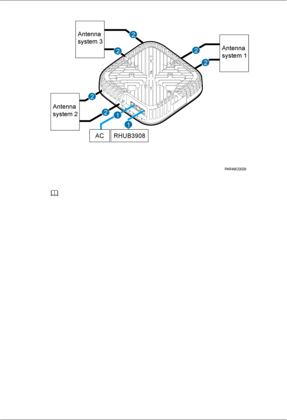
Figure 7-35 pRRU3901 cable connection (3)
(1) Ethernet cable (2) RF jumper
NOTE
lThe Extender can be used to lengthen the distance between the RHUB and the pRRU3901 connected
using the Ethernet cable. If the Extender is used, the Ethernet cable is divided into two parts, one
between the RHUB and the Extender and the other between the Extender and the pRRU3901.
lWhen two Ethernet cables are used to transmit CPRI signals, connect one end of the cables to the
CPRI_E0 and CPRI_E1 ports on the pRRU panel and the other end to any two ports of CPRI_E0 to
CPRI_E7 on the RHUB panel. On the RHUB panel, CPRI_E0 and CPRI_E1, CPRI_E2 and
CPRI_E3, CPRI_E4 and CPRI_E5, and CPRI_E6 and CPRI_E7 are used in pairs. CPRI_E0 on the
pRRU panel connects to the even-numbered CPRI port (for example, CPRI_E0, CPRI_E2,
CPRI_E4, or CPRI_E6) on the RHUB panel, and CPRI_E1 on the pRRU panel connects to the odd-
numbered CPRI port (for example, CPRI_E1, CPRI_E3, CPRI_E5, or CPRI_E7). This document
describes signal transmission using one Ethernet cable as an example.
7.5.4 Cable Connections (Outdoor)
This section describes the cable connections for a pRRU3901 installed outside.
Before installing the pRRU3901 cables, you must be aware of the following information:
lThe pRRU3901 can obtain power supply through the power over Ethernet (PoE).
lFor external antennas corresponding to RF daughter board 1, the TX port and RX port
are ANT0 and ANT1, respectively. For external antennas corresponding to RF daughter
board 2, the TX port and RX port are ANT2 and ANT3, respectively. For external
antennas corresponding to RF daughter board 3, the TX port and RX port are ANT4 and
ANT5, respectively.
lThe external antenna system is optional, and the pRRU3901 jumpers are not delivered.
By default, the pRRU3901s are configured with built-in antennas. If the external antenna
system is connected, the antenna system automatically switches to the external one. One
end of the pRRU3901 RF jumper is the SMA male connector, which is connected to the
external antenna TX/RX RF port on the pRRU3901. The other end of the pRRU3901 RF
DBS3900 LampSite
Installation Guide 7 Installing a pRRU3901
Issue 07 (2015-12-30) Huawei Proprietary and Confidential
Copyright © Huawei Technologies Co., Ltd.
91
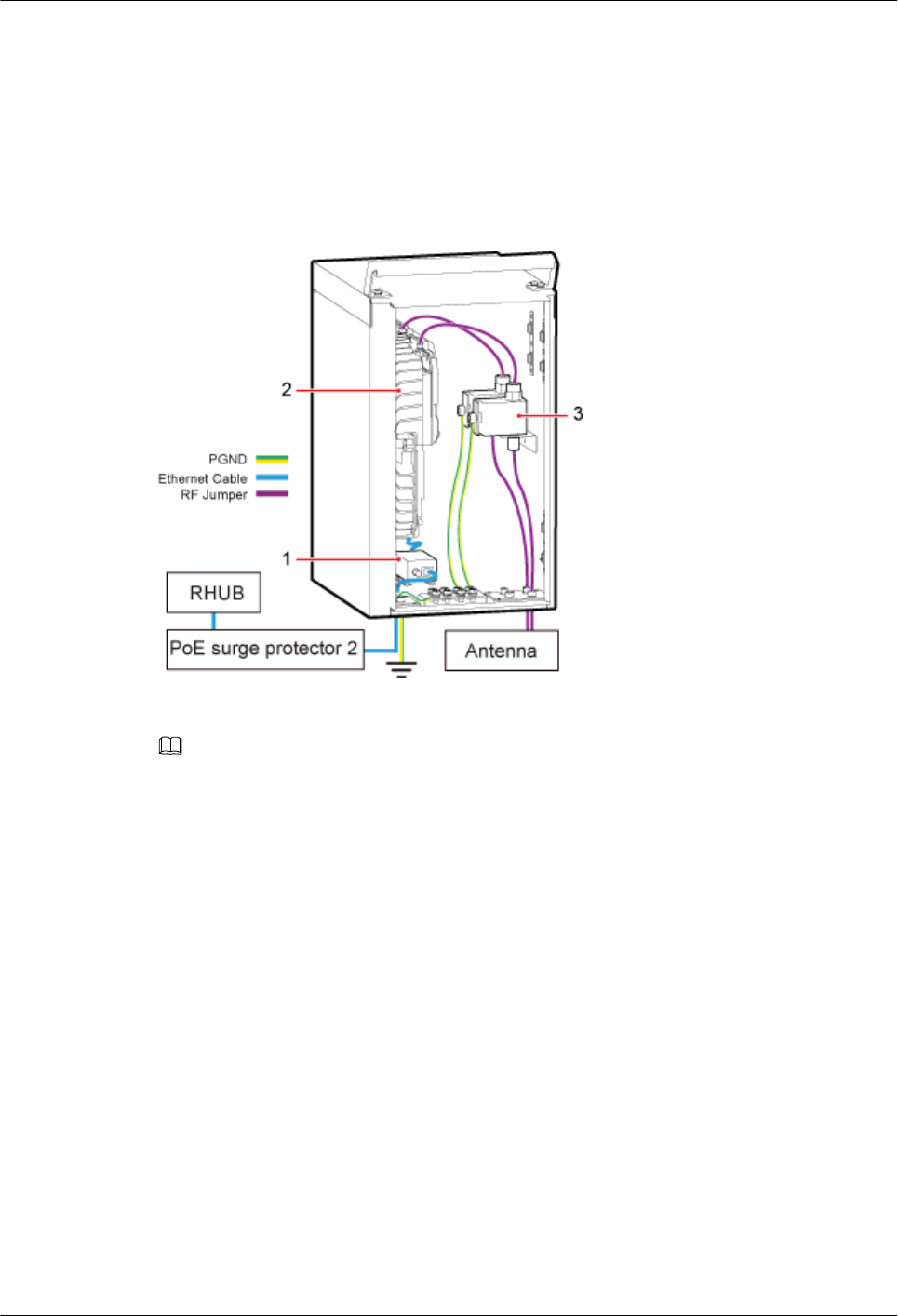
jumper is the type N male connector, which is connected to the antenna system. For the
standard of the pRRU3901 RF jumper, see (Optional) RF Jumper of the DBS3900
LampSite Hardware Description.
pRRU3901 can be configured with one RF daughter board, or two RF daughter boards, or two
RF daughter boards and one WiFi daughter board. Figure 7-36 shows the cable connection
when the pRRU3901 is configured with only one RF Daughter Board in the outside scenario.
Figure 7-36 pRRU3901 cable connection
(1) PoE surge protector 1 (2) pRRU3901 (3) RF surge protector
NOTE
lWhen two Ethernet cables are used to transmit CPRI signals, connect one end of the cables to the
CPRI_E0 and CPRI_E1 ports on the pRRU panel and the other end to any two ports of CPRI_E0 to
CPRI_E7 on the RHUB panel. On the RHUB panel, CPRI_E0 and CPRI_E1, CPRI_E2 and
CPRI_E3, CPRI_E4 and CPRI_E5, and CPRI_E6 and CPRI_E7 are used in pairs. CPRI_E0 on the
pRRU panel connects to the even-numbered CPRI port (for example, CPRI_E0, CPRI_E2,
CPRI_E4, or CPRI_E6) on the RHUB panel, and CPRI_E1 on the pRRU panel connects to the odd-
numbered CPRI port (for example, CPRI_E1, CPRI_E3, CPRI_E5, or CPRI_E7). This document
describes signal transmission using one Ethernet cable as an example.
lThe Extender can be used to lengthen the distance between the RHUB and the pRRU3901 connected
using the Ethernet cable. If the Extender is used, the Ethernet cable is divided into two parts, one
among the RHUB, PoE surge protector 2, PoE surge protector 3, Extender and the other among
Extender, PoE surge protector 4, PoE surge protector 1, pRRU3901.
lFor details about installation of the PoE surge protector and cables, see 10 (Optional) Installing the
PoE Surge Protector and Cables.
lFor details about installation of the RF surge protector and cables, see 11 (Optional) Installing the
RF Surge Protector and Cables.
7.5.5 Cable Connections (LTE TDD)
This section describes the cable connections for a single pRRU3901 and multiple pRRU3901s
in LTE TDD mode.
Before installing the pRRU3901 cables, you must be aware of the following information:
DBS3900 LampSite
Installation Guide 7 Installing a pRRU3901
Issue 07 (2015-12-30) Huawei Proprietary and Confidential
Copyright © Huawei Technologies Co., Ltd.
92
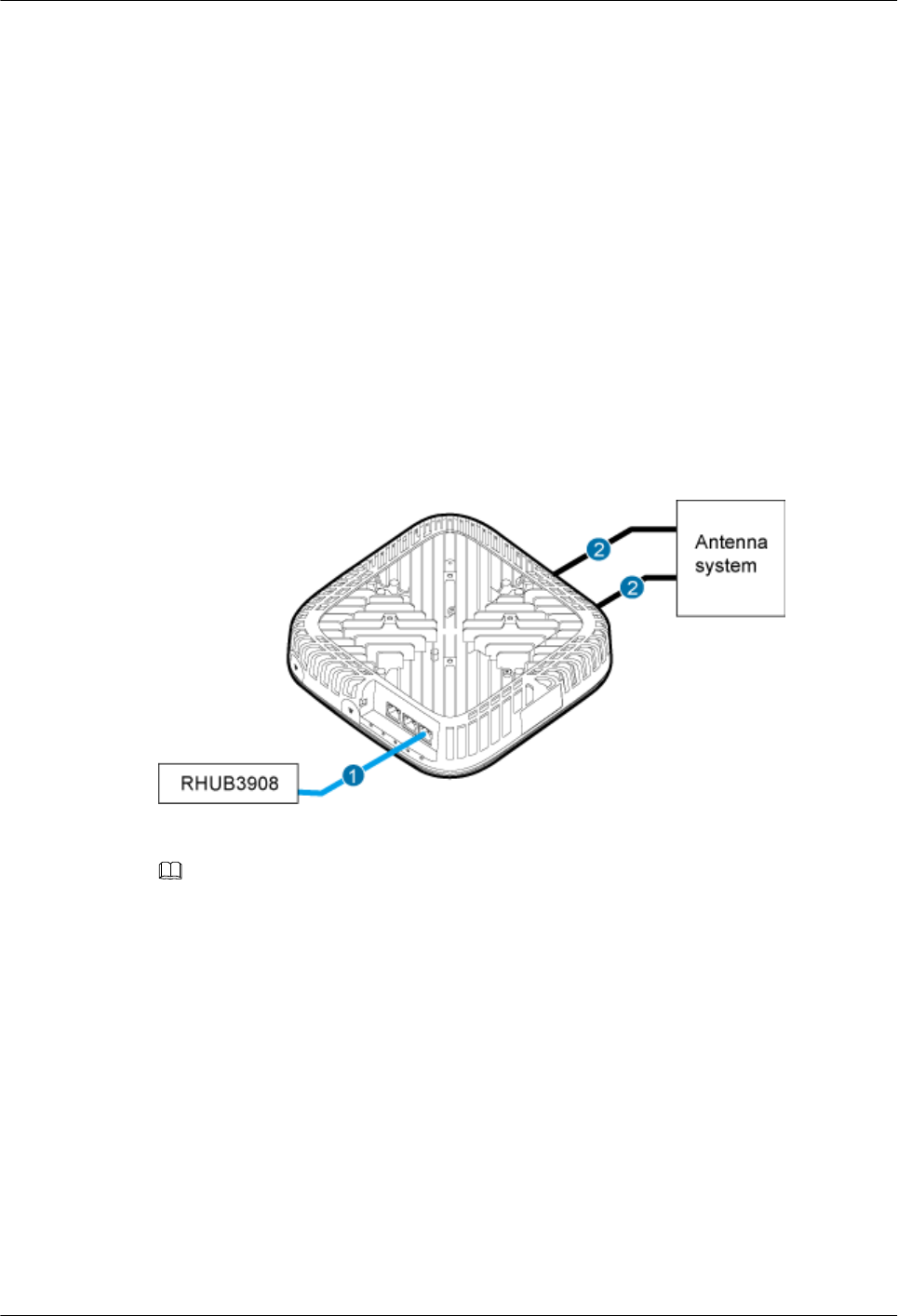
lThe pRRU3901 can obtain power supply through the power over Ethernet (PoE).
lFor external antennas corresponding to RF daughter board 1, the TX port and RX port
are ANT0 and ANT1, respectively. For external antennas corresponding to RF daughter
board 2, the TX port and RX port are ANT2 and ANT3, respectively. For external
antennas corresponding to RF daughter board 3, the TX port and RX port are ANT4 and
ANT5, respectively.
lThe external antenna system is optional, and the pRRU3901 jumpers are not delivered.
By default, the pRRU3901s are configured with built-in antennas. If the external antenna
system is connected, the antenna system automatically switches to the external one. One
end of the pRRU3901 RF jumper is the SMA male connector, which is connected to the
external antenna TX/RX RF port on the pRRU3901. The other end of the pRRU3901 RF
jumper is the type N male connector, which is connected to the antenna system. For the
standard of the pRRU3901 RF jumper, please see (Optional) RF Jumper of the DBS3900
LampSite Hardware Description.
Figure 7-37 shows the cable connection when the pRRU3901 is configured with only one RF
Daughter Board.
Figure 7-37 pRRU3901 cable connection (1)
(1) Ethernet cable (2) RF jumper
NOTE
The Extender can be used to lengthen the distance between the RHUB and the pRRU connected using
the Ethernet cable. If the Extender is used, the Ethernet cable is divided into two parts, one between the
RHUB and the Extender and the other between the Extender and the pRRU.
Figure 7-38 shows the cable connection when the pRRU3901 is configured with one RF
Daughter Boards and one Wi-Fi daughter board.
DBS3900 LampSite
Installation Guide 7 Installing a pRRU3901
Issue 07 (2015-12-30) Huawei Proprietary and Confidential
Copyright © Huawei Technologies Co., Ltd.
93
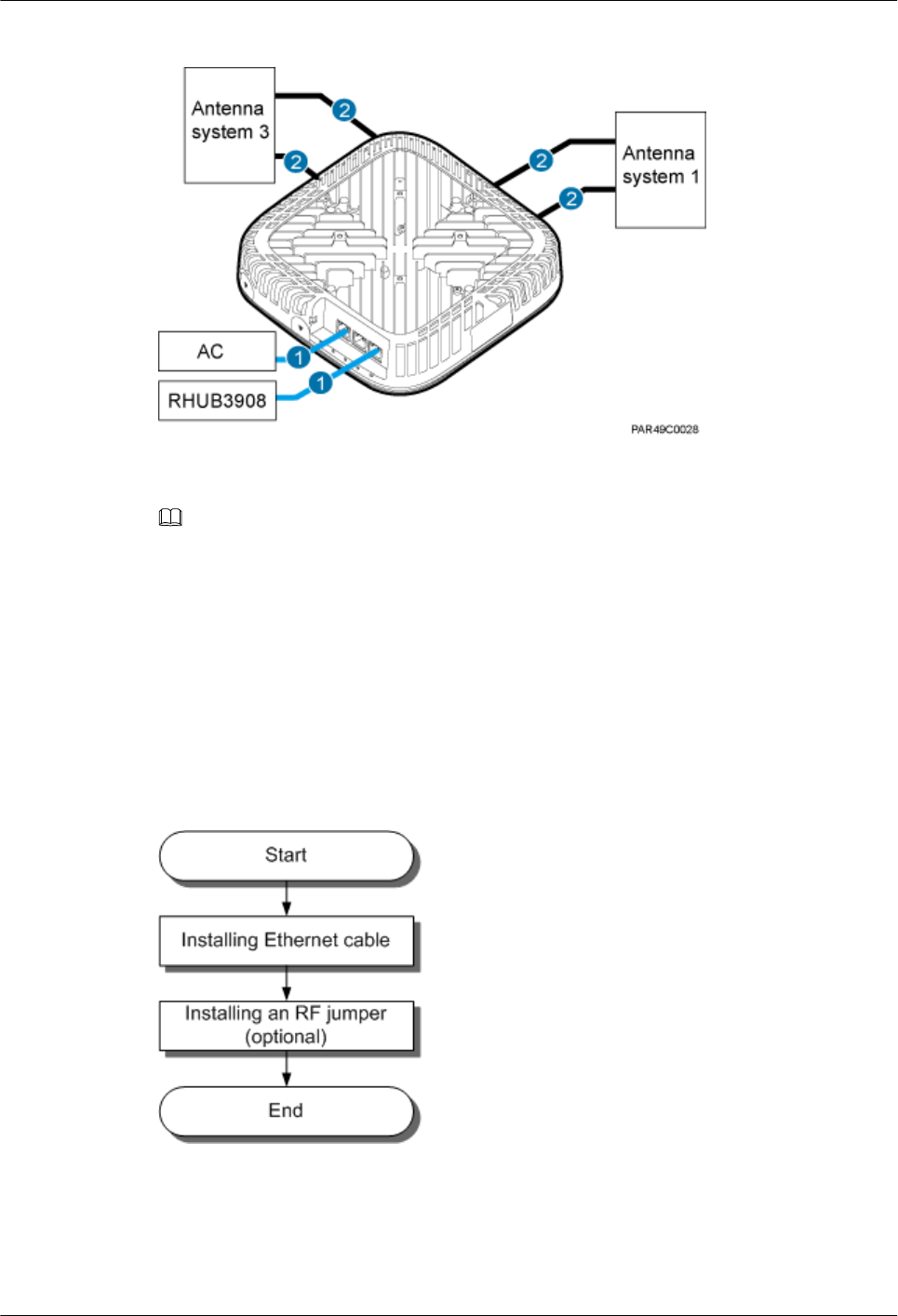
Figure 7-38 pRRU3901 cable connection (2)
(1) Ethernet cable (2) RF jumper
NOTE
The Extender can be used to lengthen the distance between the RHUB and the pRRU connected using
the Ethernet cable. If the Extender is used, the Ethernet cable is divided into two parts, one between the
RHUB and the Extender and the other between the Extender and the pRRU.
7.5.6 pRRU3901 cable installation process
This section describes the process of installing pRRU3901 cables.
Figure 7-39 shows the process of installing pRRU3901 cables.
Figure 7-39 pRRU3901 cable installation process
7.5.7 Installing an Ethernet Cable
This section describes how to install an Ethernet cable.
DBS3900 LampSite
Installation Guide 7 Installing a pRRU3901
Issue 07 (2015-12-30) Huawei Proprietary and Confidential
Copyright © Huawei Technologies Co., Ltd.
94

Prerequisites
lThe Ethernet cable must be of Category 5e (enhanced) or higher. In addition, its cross-
sectional area must be 24 AWG or larger and frame spread rating must be CM or higher.
lThe Ethernet cables can be straight-through cables or crossover cables.
lWith the internal PoE module providing power, the maximum length of an Ethernet
cable is 100 m. With the Extender, the distance of the pRRU3901 and RHUB can be
extended by the Extender up to a total distance of 200 m.
lEthernet cables are not delivered, and they must be prepared onsite. You need to use a
network cable tester to test the Ethernet cable connection.
Context
The Ethernet cable has the following functions:
lProvides power supply for the pRRU3901 when the cable connects the CPRI_E0 port on
the pRRU3901 to the RHUB.
lTransmits CPRI signals between an RHUB and a pRRU3901.
lProvides Wi-Fi services for the pRRU3901 when the cable connects the GE port on the
pRRU3901 with three transmission ports to the AC.
Using the CPRI_E1 port on the pRRU3901 has the same Ethernet cable connection to the
RHUB as using the CPRI_E0 port. The following section describes the connection using the
CPRI_E0 port.
For details about the cable connections in the different scenarios, see 7.5.3 Cable
Connections (Indoor) and 7.5.4 Cable Connections (Outdoor). The Ethernet cable
connections between RHUB and pRRUs are the same. The following section describes the
connections between RHUB-Extender-pRRU3901 as an example.
In the outdoor scenario, PoE surge protector is needed to provide surge protection for the
Ethernet ports. For details about the installation of PoE surge protector, see 10 (Optional)
Installing the PoE Surge Protector and Cables.
Procedure
Step 1 Make the Ethernet cables.
1. Assemble an RJ45 connector and an Ethernet cable by following instructions in
Assembling the Unshielded RJ45 Connector and the Ethernet Cable of Installation
Reference.
NOTE
Follow pin assignment instructions described in section Ethernet Cable in DBS3900 LampSite
Hardware Description to assemble the unshielded RJ45 connector and the Ethernet cable.
Otherwise, the transmission signal quality deteriorates and CPRI links may be disconnected.
2. Check whether the made RJ45 connector is qualified by following instructions in
Checking the Appearance of Metal Contact Strips.
3. To complete the assembly of the other end, repeat Step 1.1 and Step 1.2.
4. Check whether the touch points on the connectors at both ends are normally conducted
and well contacted and whether the connections are correct by following instructions in
Testing the Connection of Assembled Cables of Installation Reference.
Step 2 Install an Ethernet cable between an RHUB and a pRRU3901.
DBS3900 LampSite
Installation Guide 7 Installing a pRRU3901
Issue 07 (2015-12-30) Huawei Proprietary and Confidential
Copyright © Huawei Technologies Co., Ltd.
95
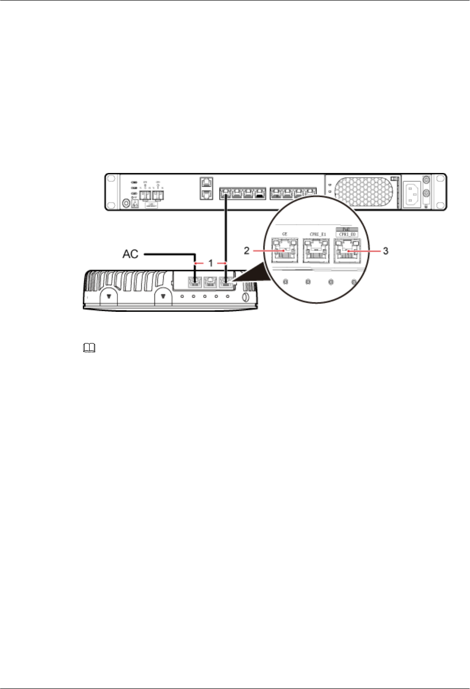
1. Remove the dustproof cap of the CPRI_E0 port on the pRRU3901.
2. Connect the RJ45 connector at one end of the Ethernet cable to the CPRI_E0 port on the
pRRU3901 panel.
3. Optional: Connect the RJ45 connector at the other end of the Ethernet cable to the
output port of the Extender. Then, connect the RJ45 connector at one end of another
Ethernet cable to the input port of the Extender.
4. Connect the RJ45 connector at the other end of the Ethernet cable to any port ranging
from CPRI_E0 to CPRI_E7 on the RHUB panel based on the engineering design, as
shown in Figure 7-40.
Figure 7-40 Installing an Ethernet cable
(1) Ethernet cable (2) GE port on the pRRU3901 (3) CPRI_E0 port on the pRRU3901
NOTE
The pRRU3901 can have two transmission ports plus one PWR port or three transmission ports (plus
one PWR port or no PWR port), requiring the same installation operations. This section uses the
pRRU3901 with three transmission ports no PWR port as an example.
Step 3 Optional: Install the Ethernet cable between the pRRU3901 and the AC. This operation is
required when the pRRU3901 with three transmission ports is configured with a Wi-Fi
daughter board.
1. Remove the dustproof cap of the GE port on the pRRU3901.
2. Connect the RJ45 connector at one end of the Ethernet cable to the GE port on the
pRRU3901 panel.
3. Connect the RJ45 connector at the other end of the Ethernet cable to the transmission
port of the AC based on the engineering design, as shown in Figure 7-40.
----End
Follow-up Procedure
1. Route the cable, and then use a cable tie to bind the cable. For details, see 7.5.1
Requirements for Cable Layout.
2. Label the installed cable. For details, see section 14.4 Attaching an L-Shaped Label.
7.5.8 Installing an RF jumpers (Optional)
The RF jumpers transmit radio frequency signals. One end of the RF jumpers is the SMA
straight male connector, and the other end is the type N connector.
DBS3900 LampSite
Installation Guide 7 Installing a pRRU3901
Issue 07 (2015-12-30) Huawei Proprietary and Confidential
Copyright © Huawei Technologies Co., Ltd.
96
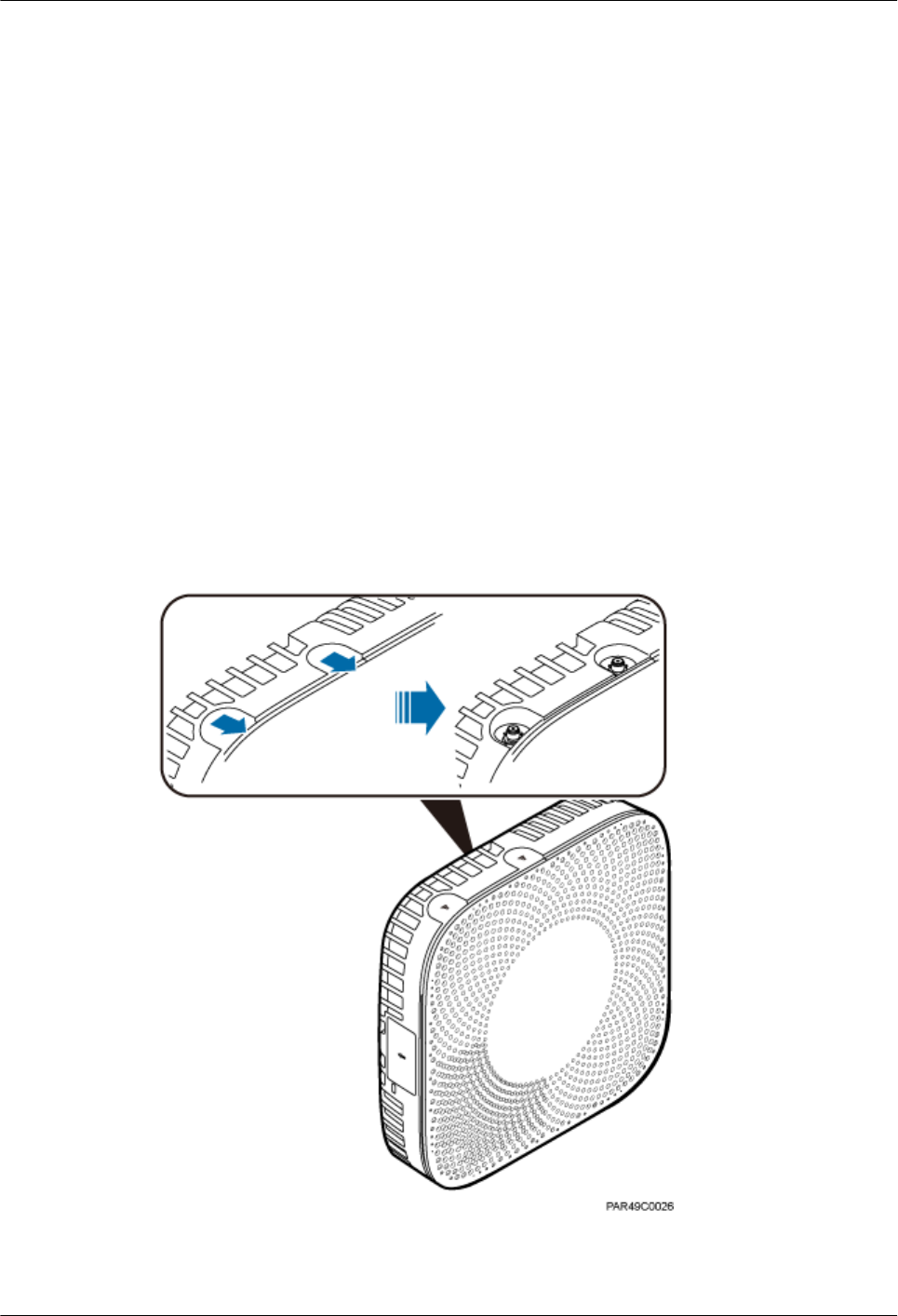
Context
lIf the RF jumper is provided by the customer, the jumper must not be lower than the
RG316 specifications. In addition, the jumpers can be used after they are checked by
Huawei engineers.
lpRRU3901s can be connected to external whip antennas or external remote antennas
(through pRRU3901 RF jumpers). Whip antennas are delivered optionally. RF jumpers
are not delivered.
lFor details about the cable connections in the different scenarios, see 7.5.3 Cable
Connections (Indoor)and 7.5.4 Cable Connections (Outdoor). The installation of RF
jumper cables are the same. The following section describes the connections between
antenna and pRRU3901 in the indoor scenario as an example.
lIn the outdoor scenario, RF surge protector is needed to provide surge protection for the
RF ports. For details about the installation of RF surge protector, see 11 (Optional)
Installing the RF Surge Protector and Cables.
Procedure
Step 1 Expose the SMA female connector by removing the pRRU3901 antenna housing, as shown in
Figure 7-41.
Figure 7-41 Removing the pRRU3901 antenna housing
Step 2 Use a torque wrench with a torque of 0.6 N•m to connect the SMA straight male connector on
a jumper to the ANT port on the pRRU3901 panel.
DBS3900 LampSite
Installation Guide 7 Installing a pRRU3901
Issue 07 (2015-12-30) Huawei Proprietary and Confidential
Copyright © Huawei Technologies Co., Ltd.
97
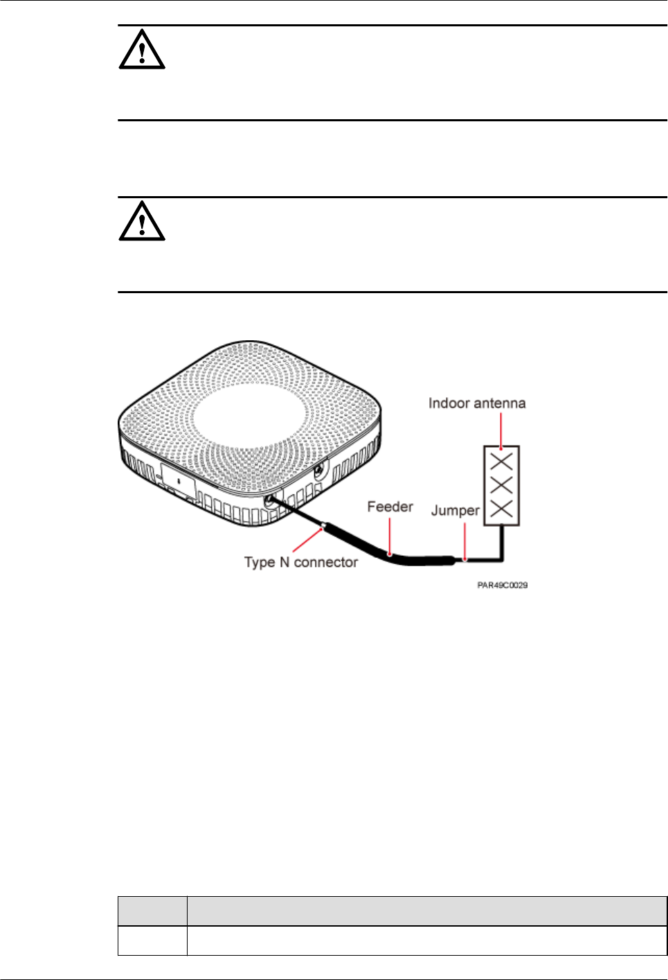
NOTICE
Tighten it with hands, and then use a torque wrench to tighten it with a rotational speed of less
than or equal to 2.4 rpm to tighten it.
Step 3 Connect the type N female connector of the jumper to the type N male connector of the RF
feeder connected to the built-in antenna.
NOTICE
Tighten the feeder close to the type N connector to ensure that the jumper is not tightened. In
this way, the connectors on both ends of a jumper are not affected by the external force.
Figure 7-42 Installing jumpers between the pRRU3901 and external antennas
----End
Follow-up Procedure
1. Route the cable, and then use a cable tie to bind the cable. For details, see 7.5.1
Requirements for Cable Layout.
2. Label the installed cable. For details, see section 14.4 Attaching an L-Shaped Label.
7.6 Checking the pRRU3901 Hardware Installation
pRRU3901 hardware installation checking includes hardware and cable installation checking.
Table 7-9 lists the hardware installation checking items.
Table 7-9 Hardware installation checking list
No. Item
1 Ensure that the pRRU3901 is not grouned.
DBS3900 LampSite
Installation Guide 7 Installing a pRRU3901
Issue 07 (2015-12-30) Huawei Proprietary and Confidential
Copyright © Huawei Technologies Co., Ltd.
98
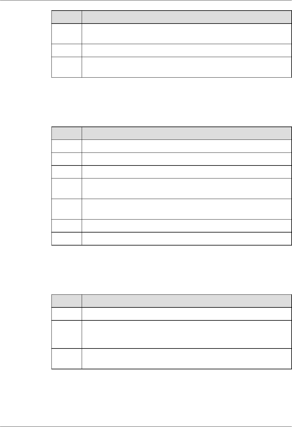
No. Item
2 The position for each device conforms to the engineering design and meets the
space requirement.
3 Ensure that the pRRU3901 is properly installed.
4 The surface of the pRRU3901 is neat and clean. The external paint is intact.
The labels, tags, and nameplates are correct, legible, and complete.
Table 7-10 lists the check items of the signal cable connection.
Table 7-10 Checklist for the signal cable connection
No. Item
1 The connectors of the signal cables must securely connected.
2 The connectors of the signal cables are intact.
3 The signal cables are intact.
4 The cable ties are evenly spaced. The signal cables are bound neatly with cable
ties to proper tightness, and arranged at even intervals in the same direction.
5 The extra length of the cable ties is cut and removed. The cut surfaces of the
indoor cables are smooth and have no sharp edges.
6 The cable layout facilitates maintenance and expansion.
7 Correct and clear labels are attached to both ends of the signal cables.
Table 7-11 lists the checking items for other cable connections.
Table 7-11 Checklist for other cable connections
No. Item
1 The connectors of the other cables must securely connected.
2 Labels on the cables are legible and bound based on the engineering
requirements. The cables must be bound tightly and neatly. The sheaths of the
cables must not be damaged.
3 Positions for routing the cables must meet requirements of the engineering
design.
DBS3900 LampSite
Installation Guide 7 Installing a pRRU3901
Issue 07 (2015-12-30) Huawei Proprietary and Confidential
Copyright © Huawei Technologies Co., Ltd.
99
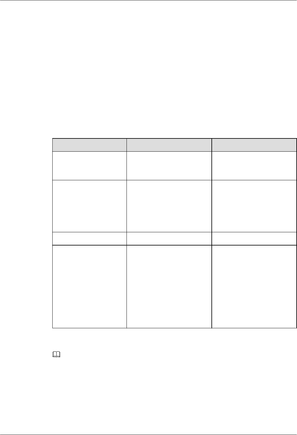
7.7 Powering on the pRRU3901
This section describes the power-on check on the pRRU3901 after the pRRU3901 hardware is
installed and checked.
Context
After the RHUB and pRRUs are installed and connected to each other, power on them no
matter whether the BBU is installed.
Procedure
Step 1 Power on the pRRU3901. Wait 3 to 5 minutes, check the status of the RUN indicator on the
pRRU3901.
If the RUN Indicator... Because... Then...
Steady on There is power input, but the
board is faulty.
Power off the power supply,
rectify the fault, and power on
the pRRU3901.
Steady off There is no power input, or an
alarm is reported on the
board.
Power off the power supply
and check the power input. If
no fault is found after the
pRRU3901 is powered off,
clear the fault on the board,
and power on the pRRU3901.
On for 1s and off for 1s The device works properly. End this operation.
On for 0.125s and off for
0.125s
The software of the board is
loading.
Wait five minutes for the
software to be successfully
loaded. If the software is
loading five minutes later,
shut off the power supply.
Check whether the data
configuration file is correct.
After the fault is rectify,
power on the pRRU3901
again.
NOTE
Check the indicator status 30 minutes after the power-on if a pRRU is not connected to any BBU. The pRRU
is considered normally powered on when any indicator on the pRRU is on.
----End
DBS3900 LampSite
Installation Guide 7 Installing a pRRU3901
Issue 07 (2015-12-30) Huawei Proprietary and Confidential
Copyright © Huawei Technologies Co., Ltd.
100

8 Installing a pRRU3902 or pRRU3911
About This Chapter
This chapter describes the pRRU3902/pRRU3911 installation process. The pRRU3902 and
pRRU3911 are installed in similar way, and this chapter uses the pRRU3902 as an example.
8.1 Information About the Installation
This section describes the information that you must be familiar with before installing a
pRRU3902 or pRRU3911, including product family, installation scenarios, installation space
and environment requirements.
8.2 Installation Process
This section describes the pRRU3902/pRRU3911 installation process, which involves
installing a pRRU, and cables, checking the pRRU hardware installation, and powering on the
pRRU.
8.3 Installing a pRRU3902 or pRRU3911
This section describes the pRRU3902/pRRU3911 installation process. A pRRU3902/
pRRU3911 can be installed on a wall, ceiling, indoor metal pole, or keel, but not on an
aluminum panel or a non-standard keel.
8.4 Installing pRRU3902 or pRRU3911 Cables
This section describes the procedure of installing the pRRU3902/pRRU3911 cables.
8.5 (Optional) Installing a Combiner
This section describes how to install a combiner. The pRRU3902 using external antennas
must be configured with a combiner.
8.6 Checking the pRRU Hardware Installation
pRRU hardware installation checking includes hardware and cable installation checking.
8.7 Powering on the pRRU
This section describes the power-on check on the pRRU3902/pRRU3911 after the pRRU
hardware is installed and checked.
DBS3900 LampSite
Installation Guide 8 Installing a pRRU3902 or pRRU3911
Issue 07 (2015-12-30) Huawei Proprietary and Confidential
Copyright © Huawei Technologies Co., Ltd.
101

8.1 Information About the Installation
This section describes the information that you must be familiar with before installing a
pRRU3902 or pRRU3911, including product family, installation scenarios, installation space
and environment requirements.
8.1.1 Product Family
This chapter describes the configurations and functions of the pRRU3902 and pRRU3911
components.
Table 8-1 lists the pRRU3902 and pRRU3911 product family.
Table 8-1 pRRU3902/pRRU3911 product family
Product
Type
Category Equipment Optional or
Mandatory
Quantity Function
pRRU390
2
Main
equipment
pRRU3902
with internal
antennas
Mandatory 1 Functions as
a remote
radio unit
that
processes
RF signals.
pRRU3902
supporting
external
antennas
Mandatory 1 Functions as
a remote
radio unit
that
processes
RF signals.
It has no
internal
antennas
and must
connect to
external
antennas.
Combiner Optional 2 Combines
signals of
RF units
operating in
different
frequency
bands.
DBS3900 LampSite
Installation Guide 8 Installing a pRRU3902 or pRRU3911
Issue 07 (2015-12-30) Huawei Proprietary and Confidential
Copyright © Huawei Technologies Co., Ltd.
102

Product
Type
Category Equipment Optional or
Mandatory
Quantity Function
Auxiliary
device
Mounting kits Mandatory 1 Supports the
pRRU3902
installation
on a wall,
ceiling,
keel, or
steel
hangers.
The
mounting
kits vary
with the
pRRU3902
installation
mode.
Cabinet Optional lNone and
one
Extender
is needed
lYes and
two
Extenders
are needed
Install the
pRRU3902
and
Extender in
the outdoor
scenario.
Extender Optional 1 or 2
NOTE
The quantity
depends on
the number of
Ethernet
cables in use.
Extends the
distance
between the
pRRU3902
and RHUB.
pRRU391
1
Main
equipment
pRRU3911
with internal
antennas
Mandatory 1 Functions as
a remote
radio unit
that
processes
RF signals.
pRRU3911
supporting
external
antennas
Mandatory 1 Functions as
a remote
radio unit
that
processes
RF signals.
DBS3900 LampSite
Installation Guide 8 Installing a pRRU3902 or pRRU3911
Issue 07 (2015-12-30) Huawei Proprietary and Confidential
Copyright © Huawei Technologies Co., Ltd.
103
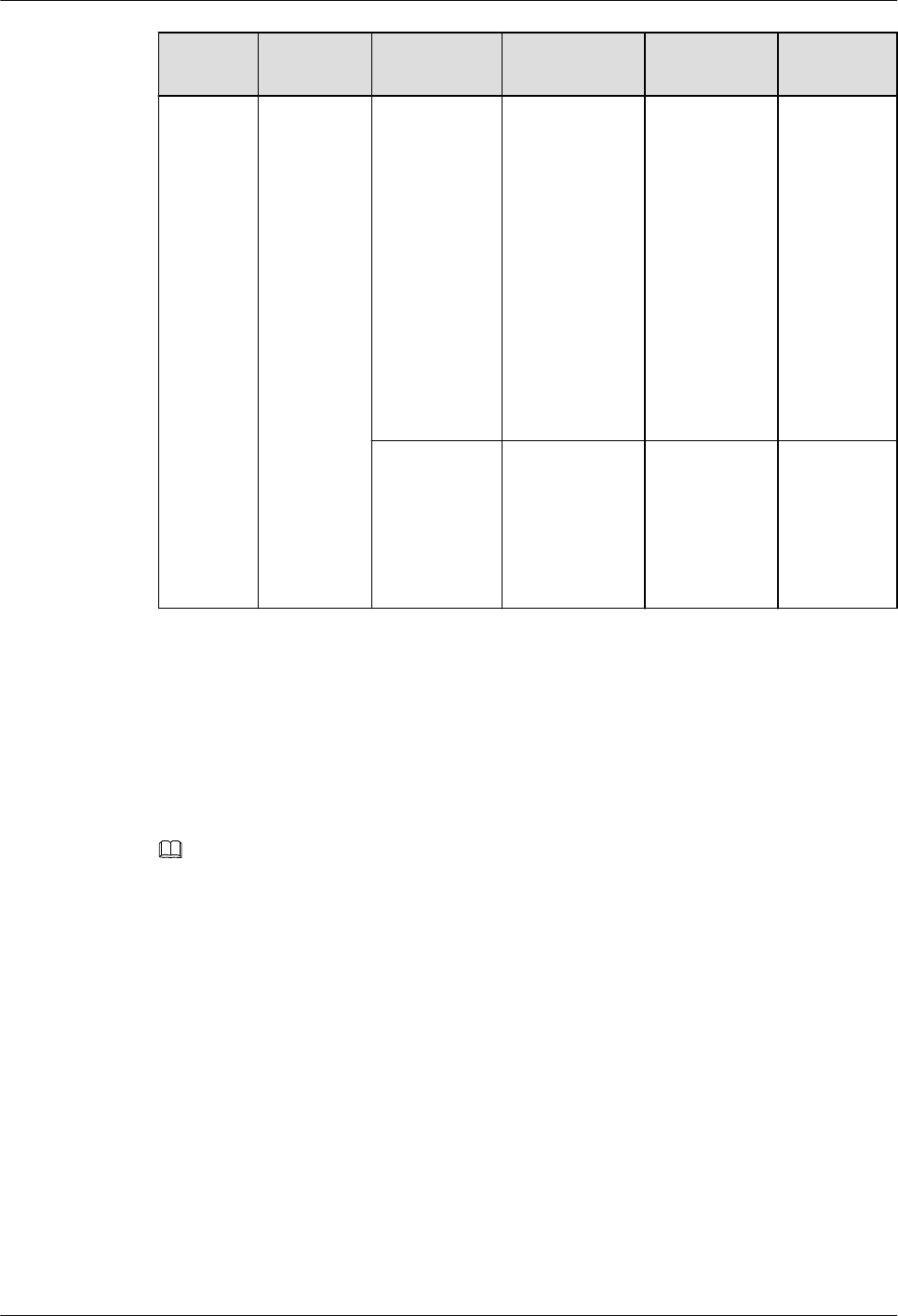
Product
Type
Category Equipment Optional or
Mandatory
Quantity Function
Auxiliary
device
Mounting kits Mandatory 1 Supports the
pRRU3911
installation
on a wall,
ceiling,
keel, or
steel
hangers.
The
mounting
kits vary
with the
installation
mode.
Extender Optional 1 or 2
NOTE
The quantity
depends on
the number of
Ethernet
cables in use.
Extends the
distance
between the
pRRU3911
and RHUB.
8.1.2 Installation Scenario
The pRRU3902/pRRU3911 can be installed on a wall, ceiling, keel, or steel hangers. The
following table describes the installation in different scenarios.
Installing on a wall
NOTE
lThe pRRU must keep a minimum of 0.5 m away from the power equipment with interference, and
keep a minimum of 2 m away from the source with radiation.
lThe pRRU must keep away from a metal wall to avoid the impact on the antenna performance.
When a pRRU3902/pRRU3911 is installed on a wall, installation modes vary with the quality
of wall, as shown in Table 8-2.
DBS3900 LampSite
Installation Guide 8 Installing a pRRU3902 or pRRU3911
Issue 07 (2015-12-30) Huawei Proprietary and Confidential
Copyright © Huawei Technologies Co., Ltd.
104
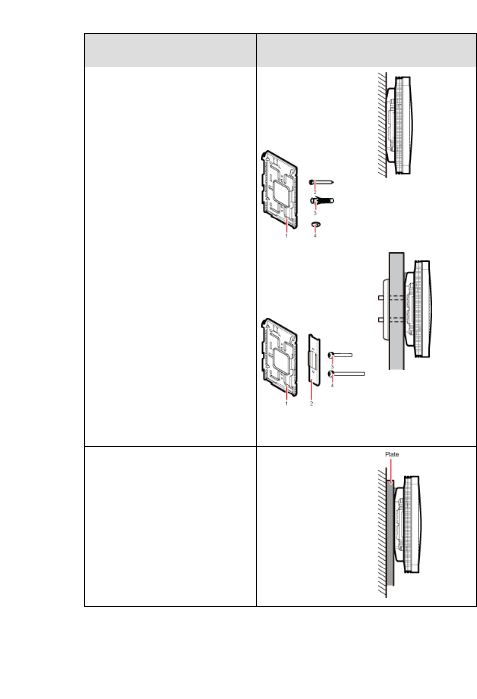
Table 8-2 Wall-mounted suggestion
Installation
Mode
Requirements Mounting Brackets Installation
Diagram
Installing the
pRRU3902 or
pRRU3911
on a wall by
drilling holes
For details,
see 8.3.2
Installing a
pRRU3902
or
pRRU3911
on a Wall.
lThe wall can bear
a load at least four
times the weight
of a pRRU.
lThe screws must
be tightened with
a torque of 1.5
N·m. This ensures
the screws work
properly and the
wall remains
intact without
cracks in it.
1. Plate
2. Screw (M3.5x35)
3. Plastic expansion
sleeve
4. Flat washer
Installing the
pRRU3902 or
pRRU3911
on a wall
using a clamp
through an
attachment
plate
For details,
see 8.3.4
Installing a
pRRU3902
or
pRRU3911
on a Plate.
lThe wall can bear
a load at least four
times the weight
of a pRRU.
lThe thickness of
the wall is less
than 45 mm.
1. Plate
2. Clamp
3. Bolt (M4x35)
4. Bolt (M4x60)
Installing the
pRRU3902 or
pRRU3911
on a wall
using a plate
on a metal
wall
The wall cannot bear
a load at least four
times the weight of
the pRRU. For
example, EPS walls,
MDF walls, or walls
cannot be drilled.
The plate is prepared by
customers.
Installing on a ceiling
When a pRRU3902/pRRU3911 is installed on a ceiling, installation modes vary with the
quality of the ceiling, as shown in Table 8-3.
DBS3900 LampSite
Installation Guide 8 Installing a pRRU3902 or pRRU3911
Issue 07 (2015-12-30) Huawei Proprietary and Confidential
Copyright © Huawei Technologies Co., Ltd.
105
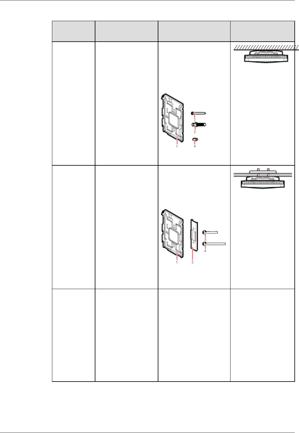
Table 8-3 Ceiling-mounted suggestion
Installation
Mode
Requirements Mounting Brackets Installation
Diagram
Installing the
pRRU3902 or
pRRU3911
on a ceiling
by drilling
holes
For details,
see 8.3.3
Installing a
pRRU3902
or
pRRU3911
on a Ceiling.
lThe ceiling, such
as a concrete
ceiling, can bear a
load at least four
times the weight
of the pRRU.
lThe screws must
be tightened with
a torque of 1.5
N·m. This ensures
the screws work
properly and the
ceiling remains
intact without
cracks in it.
1. Plate
2. Screw (M3.5 x 35)
3. Plastic expansion
sleeve
4. Flat washer
Installing the
pRRU3902 or
pRRU3911
on a ceiling
using a clamp
through an
attachment
plate
For details,
see 8.3.4
Installing a
pRRU3902
or
pRRU3911
on a Plate.
lThe ceiling, such
as a concrete
ceiling, can bear a
load at least four
times the weight
of the pRRU.
lThe thickness of
the ceiling is less
than 45 mm.
1. Plate
2. U-shaped metal plate
3. Bolt (M4 x 35)
4. Bolt (M4 x 60)
Installing the
pRRU3902 or
pRRU3911
on a keel
For details,
see 8.3.5
Installing a
pRRU3902
or
pRRU3911
on a Keel.
A keel under the
ceiling can bear a
load at least four
times the weight of
the pRRU.
For details, see Table
8-4.
For details, see Table
8-4.
DBS3900 LampSite
Installation Guide 8 Installing a pRRU3902 or pRRU3911
Issue 07 (2015-12-30) Huawei Proprietary and Confidential
Copyright © Huawei Technologies Co., Ltd.
106
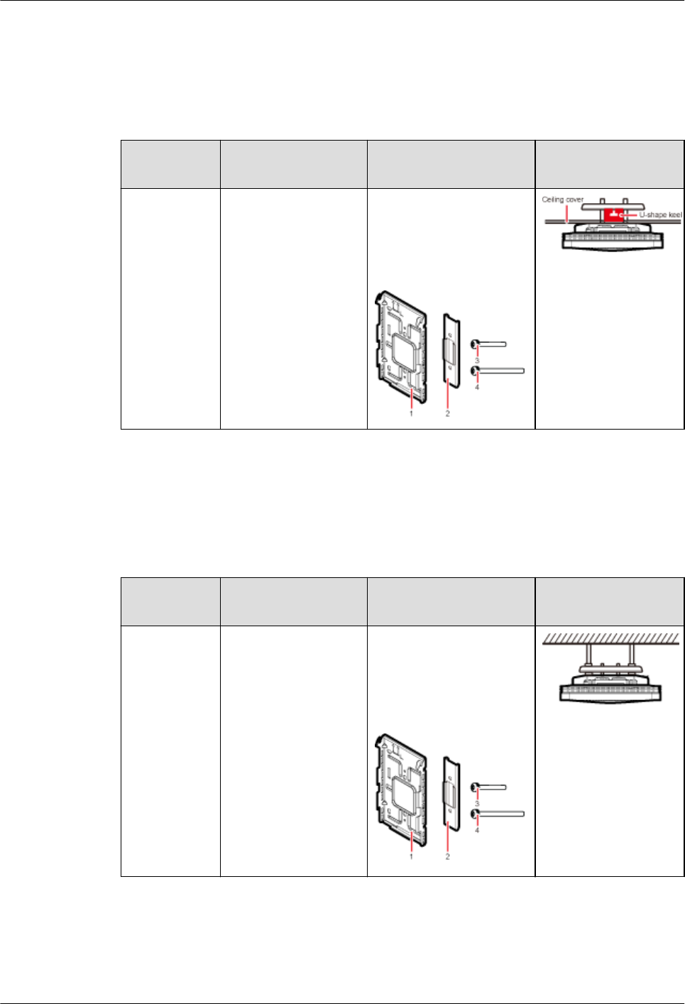
Installing on a keel
The pRRU3902/pRRU3911 can be installed on a keel of U-shape, T-shape, or H-shape. For
the keels of other shapes, they are determined based on the onsite requirements.
Table 8-4 Keel-mounted installation suggestion
Installation
Mode
Requirements Mounting Brackets Installation
Diagram
Installing the
pRRU3902 or
pRRU3911
on a keel
For details,
see 8.3.5
Installing a
pRRU3902
or
pRRU3911
on a Keel.
The keel is in U-
shape, T-shape, H-
shape, or other
shapes.
1. Plate
2. U-shaped metal plate
3. Bolt (M4 x 35)
4. Bolt (M4 x 60) shows the
pRRU3902 /
pRRU3911 installed
on a U-shaped keel.
Installing on a on steel hangers
Either M6 or M8 steel hangers can be used for installation.
Table 8-5 Steel hangers installation suggestion
Installation
Mode
Requirements Mounting Brackets Installation
Diagram
Installing the
pRRU3902 or
pRRU3911
on a steel
hangers
For details,
see 8.3.6
Installing a
pRRU3902
or
pRRU3911
on Steel
Hangers.
Either M6 or M8
steel hangers can be
used for installation.
1. Plate
2. U-shaped metal plate
3. Bolt (M4 x 35)
4. Bolt (M4 x 60)
Cabinet
In the outside scenario, pRRU3902 should be installed in the cabinet.
DBS3900 LampSite
Installation Guide 8 Installing a pRRU3902 or pRRU3911
Issue 07 (2015-12-30) Huawei Proprietary and Confidential
Copyright © Huawei Technologies Co., Ltd.
107
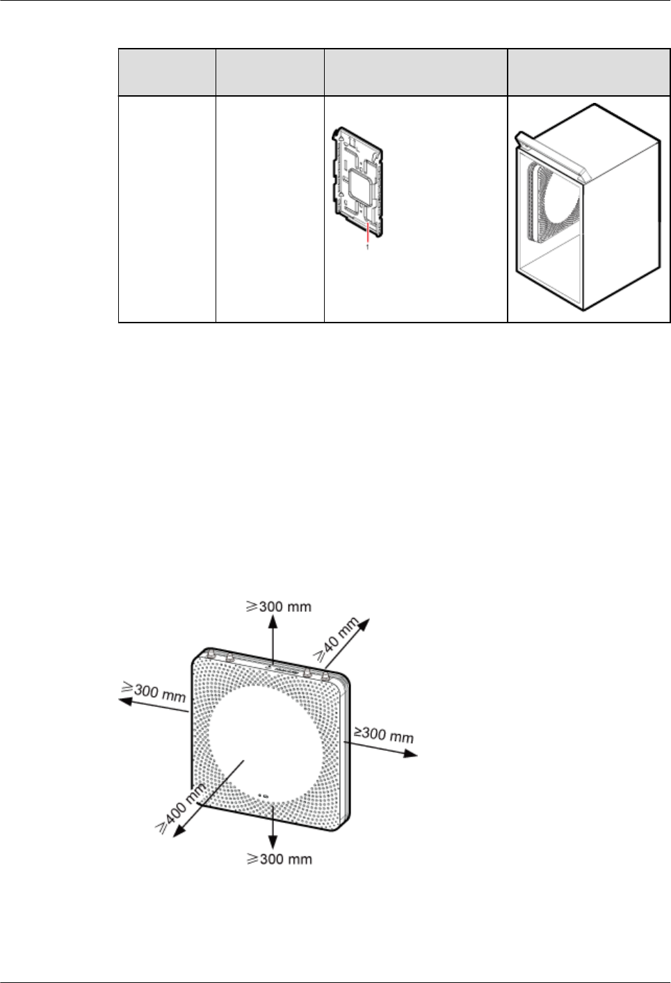
Table 8-6 Cabinet installation suggestion
Installation
Mode
Requirement
s
Mounting Brackets Installation Diagram
Installing the
cabinet For
details, see
8.3.7
Installing the
Cabinet.
–1. Plate
8.1.3 Space Requirements
This chapter describes the space requirements of the pRRU3902 or pRRU3911.
When the pRRU3902/pRRU3911 is installed on a wall, ceiling, pole or keel, the minimum
space is required for easy cabling and O&M. Based on the engineering practice, the
recommendation for the installation space is provided.
Figure 8-1 shows the recommended space requirements of the pRRU when the external
antenna is required.
Figure 8-1 Recommended space requirements
When the external antenna is required, the recommended space for installing a single
pRRU3902/pRRU3911 is described as follows:
lAt least 300 mm above the pRRU is reserved for maintenance.
DBS3900 LampSite
Installation Guide 8 Installing a pRRU3902 or pRRU3911
Issue 07 (2015-12-30) Huawei Proprietary and Confidential
Copyright © Huawei Technologies Co., Ltd.
108
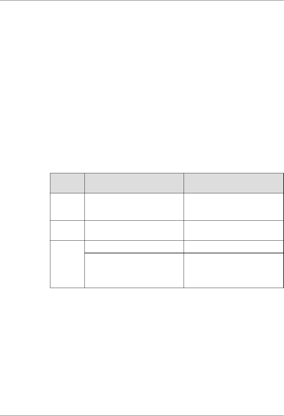
lAt least 300 mm under the pRRU is reserved for cabling.
lAt least 300 mm on the left of the pRRU is reserved for maintenance.
lAt least 300 mm on the right of the pRRU is reserved for maintenance.
lAt least 400 mm in front of the pRRU is reserved for maintenance
lAt least 40 mm on the back of the pRRU is reserved for ventilation.
In the outdoor scenario, there is no space requirement for the pRRU3902 installing in the
cabinet.
8.1.4 Installation Environment Requirements
The installation environment of a pRRU3902 or a pRRU3911 involves the running
environment specifications for the pRRU3902/pRRU3911 and other specifications.
Running Environment Specifications
Table 8-7 shows the environment specifications for the pRRU3902/pRRU3911 installed
indoors.
Table 8-7 environment specifications
Specificat
ions
Condition Remarks
Operating
temperatur
e
lIndoor: - 5 °C to + 40 °C
lOutside: - 20 °C to + 40 °C
-
Relative
humidity
5% RH to 95% RH -
Altitude - 60 m to + 1800 m Works properly.
1800 m to 4000 m Above the 1800 m altitude, the
maximum operating temperature
decreases by 1°C each time the
altitude increases by 220 m.
Other Running Environment Specifications
lThe pRRU cannot be installed at an air outlet of the heat dissipation box of an air
conditioner or other heat-generating appliances.
lThe pRRU cannot be installed near a strong heat source.
lThe pRRU cannot be installed in a position with water dripping, such as outdoor
equipment of air conditioners, pipe, and leaking or dripping roofs.
lThe installation position must be far from rains. If the pRRU is installed on a wall, there
must be no window on either side of the wall.
lThe installation position must be far away from high voltage, highly corrosive devices,
flammable or explosive substances, and electromagnetic interference such as power
stations, high-voltage substations, and wired TV towers.
DBS3900 LampSite
Installation Guide 8 Installing a pRRU3902 or pRRU3911
Issue 07 (2015-12-30) Huawei Proprietary and Confidential
Copyright © Huawei Technologies Co., Ltd.
109
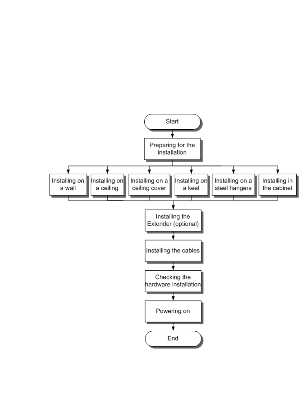
lThe pRRU must be installed in a dry, ventilating, and dust-proof place.
lIf the pRRU is installed in parking areas or basements, the installation position must be
well-ventilated.
8.2 Installation Process
This section describes the pRRU3902/pRRU3911 installation process, which involves
installing a pRRU, and cables, checking the pRRU hardware installation, and powering on the
pRRU.
Figure 8-2 shows the pRRU3902/pRRU3911 installation process.
Figure 8-2 Installation process
8.3 Installing a pRRU3902 or pRRU3911
This section describes the pRRU3902/pRRU3911 installation process. A pRRU3902/
pRRU3911 can be installed on a wall, ceiling, indoor metal pole, or keel, but not on an
aluminum panel or a non-standard keel.
DBS3900 LampSite
Installation Guide 8 Installing a pRRU3902 or pRRU3911
Issue 07 (2015-12-30) Huawei Proprietary and Confidential
Copyright © Huawei Technologies Co., Ltd.
110
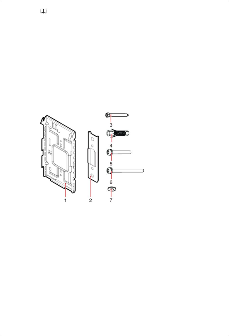
NOTE
Note the following when installing the pRRU3902/pRRU3911:
lThe pRRU cannot be grounded. If the pRRU is grounded but the RHUB connected to this pRRU is not,
the pRRU may fail to be powered on.
lA minimum distance of 50 cm must be reserved between the pRRU and the incandescent lamp.
lThe installation spacing between the pRRU and the temperature sensor must be greater than 50 cm.
lIt is good practice to install the pRRU on materials that can tolerate a temperature higher than 65°C and
have an ignition point higher than 70°C.
8.3.1 Mounting Kits
This section describes the pRRU3902/pRRU3911 mounting kits.
Figure 8-3 shows the exterior of the pRRU3902/pRRU3911 mounting kits.
Figure 8-3 Mounting kits
(1) Mounting bracket (2) U-shaped metal plate (3) Screw (3.5X35)
(4) Plastic expansion sleeve (5) Bolt (M4X35) (6) Bolt (M4X60)
(7) Flat washer – –
Figure 8-4, Figure 8-5 show the specifications of the mounting bracket.
DBS3900 LampSite
Installation Guide 8 Installing a pRRU3902 or pRRU3911
Issue 07 (2015-12-30) Huawei Proprietary and Confidential
Copyright © Huawei Technologies Co., Ltd.
111

Figure 8-4 Mounting bracket specifications
Figure 8-5 U-shaped metal plate specifications
8.3.2 Installing a pRRU3902 or pRRU3911 on a Wall
This section describes how to install a pRRU3902/pRRU3911 on an indoor wall. If a wall
indoors has adequate load bearing capacity and installation space, it is good practice to install
the pRRU on the wall. If the wall does not have adequate load bearing capacity, choose an
installation mode based on site requirements.
Context
NOTE
This section describes only the wall-mounted installation in which mounting kits are directly installed on the
wall without auxiliary devices. The procedure for other wall-mounted installation modes is similar.
Procedure
Step 1 Determine the position for installing the pRRU based on the construction blueprint and the
clearance requirements.
NOTE
For details about the clearance requirements, see 8.1.3 Space Requirements.
DBS3900 LampSite
Installation Guide 8 Installing a pRRU3902 or pRRU3911
Issue 07 (2015-12-30) Huawei Proprietary and Confidential
Copyright © Huawei Technologies Co., Ltd.
112
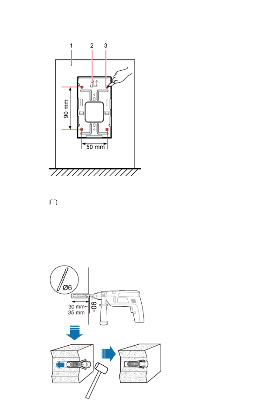
Step 2 Place the mounting bracket in the installation position against the wall. Then, level the
mounting bracket and use a marker to mark four anchor points. See Figure 8-6.
Figure 8-6 Anchor points on the pRRU3902/pRRU3911 mounting bracket
(1) Wall (2) Mounting bracket (3) Anchor point
NOTE
To prevent inhalation or eye contact with dust, take adequate preventive measures when drilling holes.
Step 3 Use a hammer drill with φ6 bore to drill holes at the marked anchor points, as shown in
Figure 8-7. Use a vacuum cleaner to clean the dust inside and around the holes and measure
the distance between them. If they are inaccurately positioned, re-measure and re-drill the
holes. Then, use a rubber mallet to hit a plastic expansion sleeve into each hole.
Figure 8-7 Drilling holes and installing expansion bolts
DBS3900 LampSite
Installation Guide 8 Installing a pRRU3902 or pRRU3911
Issue 07 (2015-12-30) Huawei Proprietary and Confidential
Copyright © Huawei Technologies Co., Ltd.
113
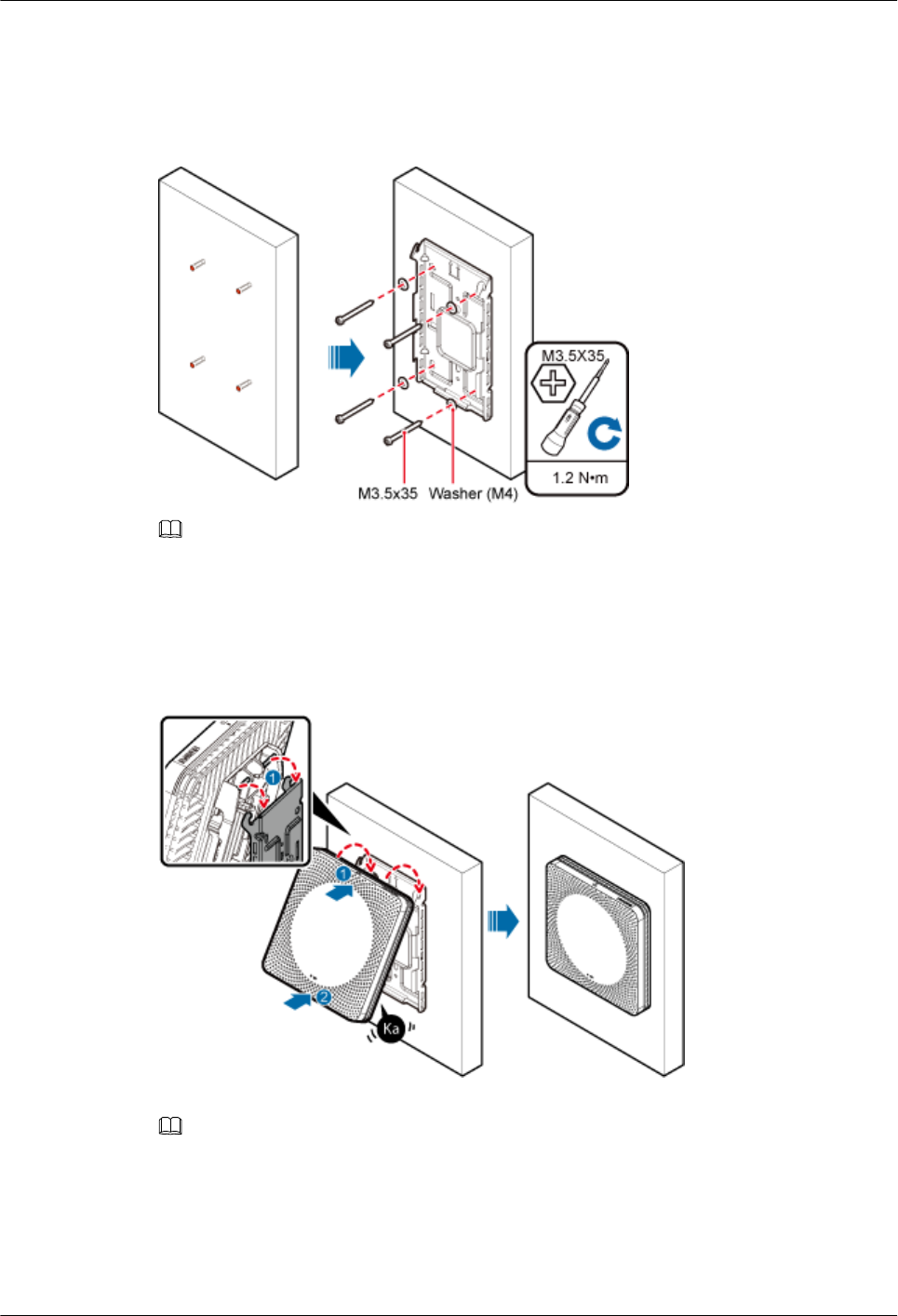
Step 4 Lead the M3.5x35 screws through the washers, and then through the drilling holes on the
mounting bracket to the plastic expansion sleeves, and torque the screws to 1.2 N•m, as
shown in Figure 8-8.
Figure 8-8 Installing the mounting bracket
NOTE
If the screws cannot be tightened using a Phillips screwdriver, use a hex key or an electric screwdriver to
assist the installation.
Step 5 Fit the rotation axis on the pRRU into the hooks on the mounting bracket, and then push the
pRRU against the mounting bracket until a click is heard. See Figure 8-9.
Figure 8-9 Installing a pRRU3902/pRRU3911 on a wall
NOTE
lBefore installing the pRRU, connect one end of the Ethernet cable to the CPRI_E0 port on pRRU.
lIt is good practice to perform the installation from the side view to promptly align the hooks with the
rotation axis.
Step 6 Optional: Use T20 with hole screwdriver to lock the protection screw on the attachment
plate. See Figure 8-10.
DBS3900 LampSite
Installation Guide 8 Installing a pRRU3902 or pRRU3911
Issue 07 (2015-12-30) Huawei Proprietary and Confidential
Copyright © Huawei Technologies Co., Ltd.
114
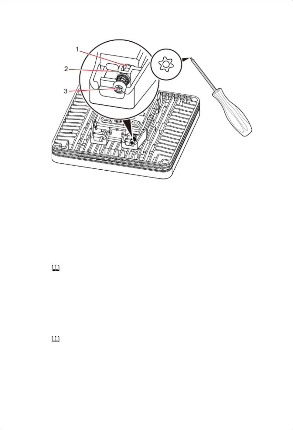
The protection screw protects the pRRU from being removed and must be locked if required.
Figure 8-10 Locking the protection screw
(1) M4 threaded hole (2) Hole for self-tapping screws (3) Quincunx screw
----End
8.3.3 Installing a pRRU3902 or pRRU3911 on a Ceiling
This section describes how to install a pRRU3902/pRRU3911 on the ceiling, such as the
concrete ceiling, when the ceiling has adequate load bearing capacity and installation space.
Context
NOTE
If the pRRU3902/pRRU3911 is installed on a ceiling, the temperature of the ceiling may increase by a
maximum of 30 degrees. Therefore, whether a pRRU can be installed on a ceiling depends on the ceiling
material.
Procedure
Step 1 Determine the position for installing the pRRU based on the construction blueprint and the
clearance requirements.
NOTE
For details about the clearance requirements, see 8.1.3 Space Requirements.
Step 2 Place the mounting bracket in the installation position against the ceiling. Then, level the
mounting bracket and use a marker to mark four anchor points. See Figure 8-11.
DBS3900 LampSite
Installation Guide 8 Installing a pRRU3902 or pRRU3911
Issue 07 (2015-12-30) Huawei Proprietary and Confidential
Copyright © Huawei Technologies Co., Ltd.
115
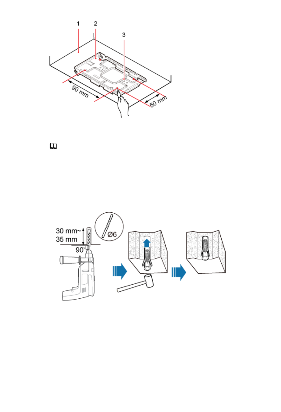
Figure 8-11 Anchor points on the pRRU3902/pRRU3911 mounting bracket
(1) Ceiling (2) Mounting bracket (3) Anchor point
NOTE
To prevent inhalation or eye contact with dust, take adequate preventive measures when drilling holes.
Step 3 Use a hammer drill with φ6 bore to drill holes at the marked anchor points, as shown in
Figure 8-12. Use a vacuum cleaner to clean the dust inside and around the holes and measure
the distance between them. If they are inaccurately positioned, re-measure and re-drill the
holes. Then, use a rubber mallet to hit a plastic expansion sleeve into each hole.
Figure 8-12 Drilling holes and installing expansion bolts
Step 4 Lead the M3.5x35 screws through the washers, and then through the drilling holes on the
mounting bracket to the plastic expansion sleeves, and use a torque screwdriver to torque the
screws to 1.2 N•m, as shown in Figure 8-13.
DBS3900 LampSite
Installation Guide 8 Installing a pRRU3902 or pRRU3911
Issue 07 (2015-12-30) Huawei Proprietary and Confidential
Copyright © Huawei Technologies Co., Ltd.
116
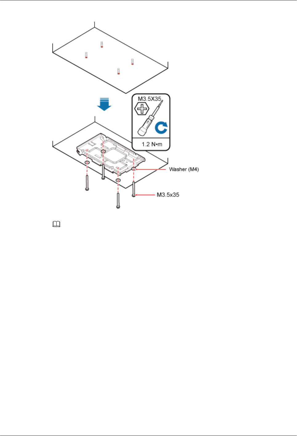
Figure 8-13 Installing the mounting bracket
NOTE
If the screws cannot be tightened using a Phillips screwdriver, use a hex key or an electric screwdriver to
assist the installation.
Step 5 Fit the rotation axis on the pRRU into the hooks on the mounting bracket, and then push the
pRRU against the mounting bracket until a click is heard. See Figure 8-14.
DBS3900 LampSite
Installation Guide 8 Installing a pRRU3902 or pRRU3911
Issue 07 (2015-12-30) Huawei Proprietary and Confidential
Copyright © Huawei Technologies Co., Ltd.
117
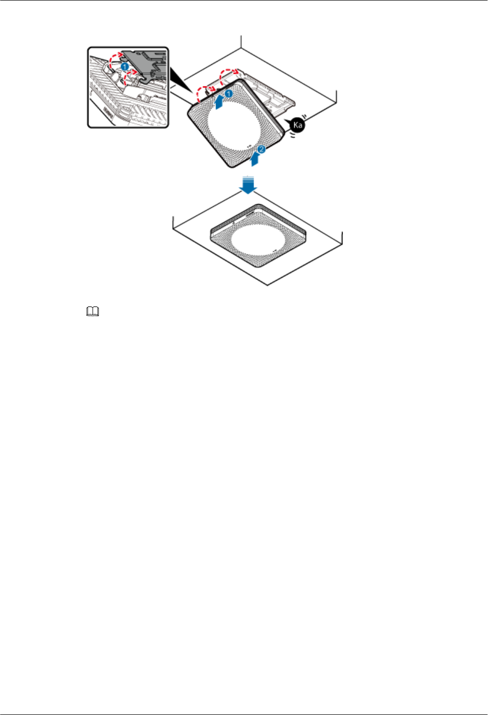
Figure 8-14 Installing a pRRU3902/pRRU3911 on a ceiling
NOTE
lBefore installing the pRRU, connect one end of the Ethernet cable to the CPRI_E0 port on pRRU.
lIt is good practice to perform the installation from the side view to promptly align the hooks with the
rotation axis.
Step 6 Optional: Use T20 with hole screwdriver to lock the protection screw on the attachment
plate. See Figure 8-15.
The protection screw protects the pRRU from being removed and must be locked if required.
DBS3900 LampSite
Installation Guide 8 Installing a pRRU3902 or pRRU3911
Issue 07 (2015-12-30) Huawei Proprietary and Confidential
Copyright © Huawei Technologies Co., Ltd.
118

Figure 8-15 Locking the protection screw
(1) M4 threaded hole (2) Hole for self-tapping screws (3) Quincunx screw
----End
8.3.4 Installing a pRRU3902 or pRRU3911 on a Plate
This section describes how to install a pRRU3902/pRRU3911 on a plate. If a suspended
ceiling plate has adequate load bearing capacity and installation space, the pRRU3902/
pRRU3911 can be installed on the plate. However, it is good practice not to install a pRRU on
an aluminum plate. The installation modes are classified into installation on a removable
suspended ceiling plate and installation on an overall suspended ceiling.
Procedure
lInstallation on a removable suspended ceiling plate
This installation mode applies when the suspended ceiling plate (for example, a metal
plate) is removable.
a. Determine the position for installing the pRRU based on the construction blueprint
and the clearance requirements.
NOTE
For details about the clearance requirements, see 8.1.3 Space Requirements.
b. Place the mounting bracket in the installation position against the wall. Then, level
the mounting bracket and use a marker to mark two anchor points. See Figure 8-16.
DBS3900 LampSite
Installation Guide 8 Installing a pRRU3902 or pRRU3911
Issue 07 (2015-12-30) Huawei Proprietary and Confidential
Copyright © Huawei Technologies Co., Ltd.
119
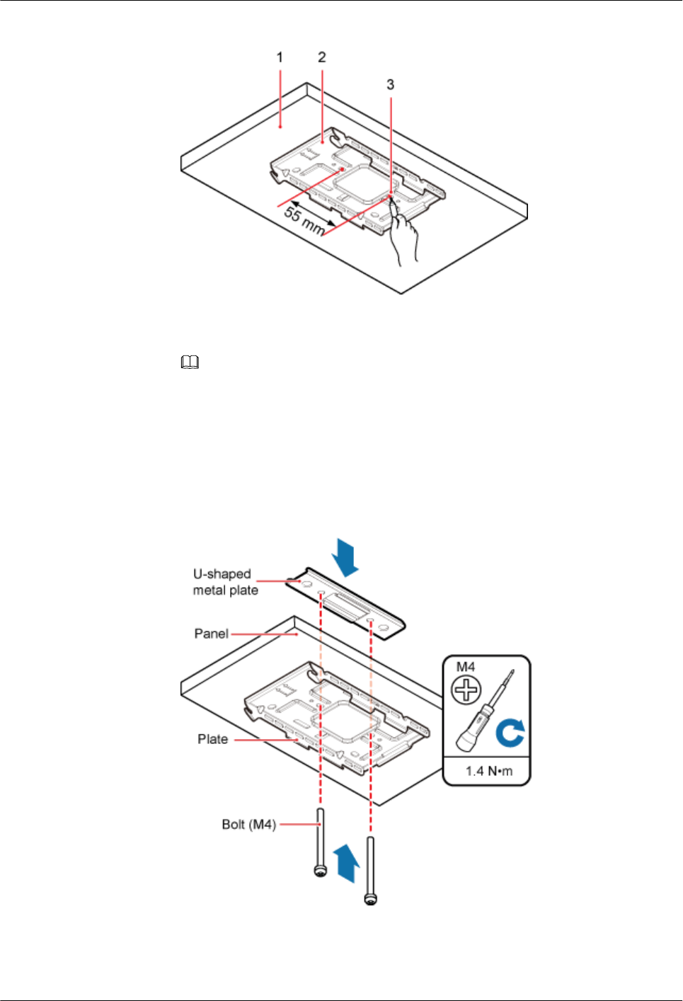
Figure 8-16 Anchor points on the pRRU3902/pRRU3911 mounting bracket
(1) Suspended ceiling plate (2) Mounting bracket (3) Anchor point
NOTE
To prevent inhalation or eye contact with dust, take adequate preventive measures when
drilling holes.
c. Use a hammer drill with φ6 bore to drill holes at the anchor points.
d. Lead two bolts (M4) through the mounting bracket and the suspended ceiling plate,
and use a torque screwdriver to torque the bolts to 1.4 N•m, as shown in Figure
8-17.
Figure 8-17 Installing the pRRU3902/pRRU3911 mounting bracket
DBS3900 LampSite
Installation Guide 8 Installing a pRRU3902 or pRRU3911
Issue 07 (2015-12-30) Huawei Proprietary and Confidential
Copyright © Huawei Technologies Co., Ltd.
120
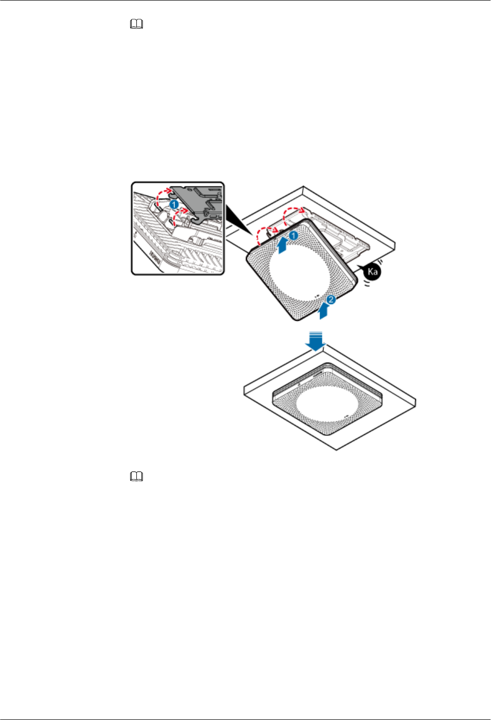
NOTE
lThe bolt used for installing the pRRU on a suspended ceiling plate depends on the plate
thickness:
lThe delivered bolt (M4x35) is used if the plate thickness is less than 25 mm.
lThe delivered bolt (M4X60) is used if the plate thickness ranges from 25 mm to 45 mm.
lIf the screws cannot be tightened using a Phillips screwdriver, use a hex key or an electric
screwdriver to assist the installation.
e. Fit the rotation axis on the pRRU into the hooks on the mounting bracket, and then
push the pRRU against the mounting bracket until a click is heard. See Figure 8-18.
Figure 8-18 Installing a pRRU3902/pRRU3911 on a plate
NOTE
If the screws cannot be tightened using a Phillips screwdriver, use a hex key or an electric
screwdriver to assist the installation.
f. Use T20 with hole screwdriver to lock the protection screw on the attachment plate.
See Figure 8-19.
The protection screw protects the pRRU from being removed and must be locked if
required.
DBS3900 LampSite
Installation Guide 8 Installing a pRRU3902 or pRRU3911
Issue 07 (2015-12-30) Huawei Proprietary and Confidential
Copyright © Huawei Technologies Co., Ltd.
121
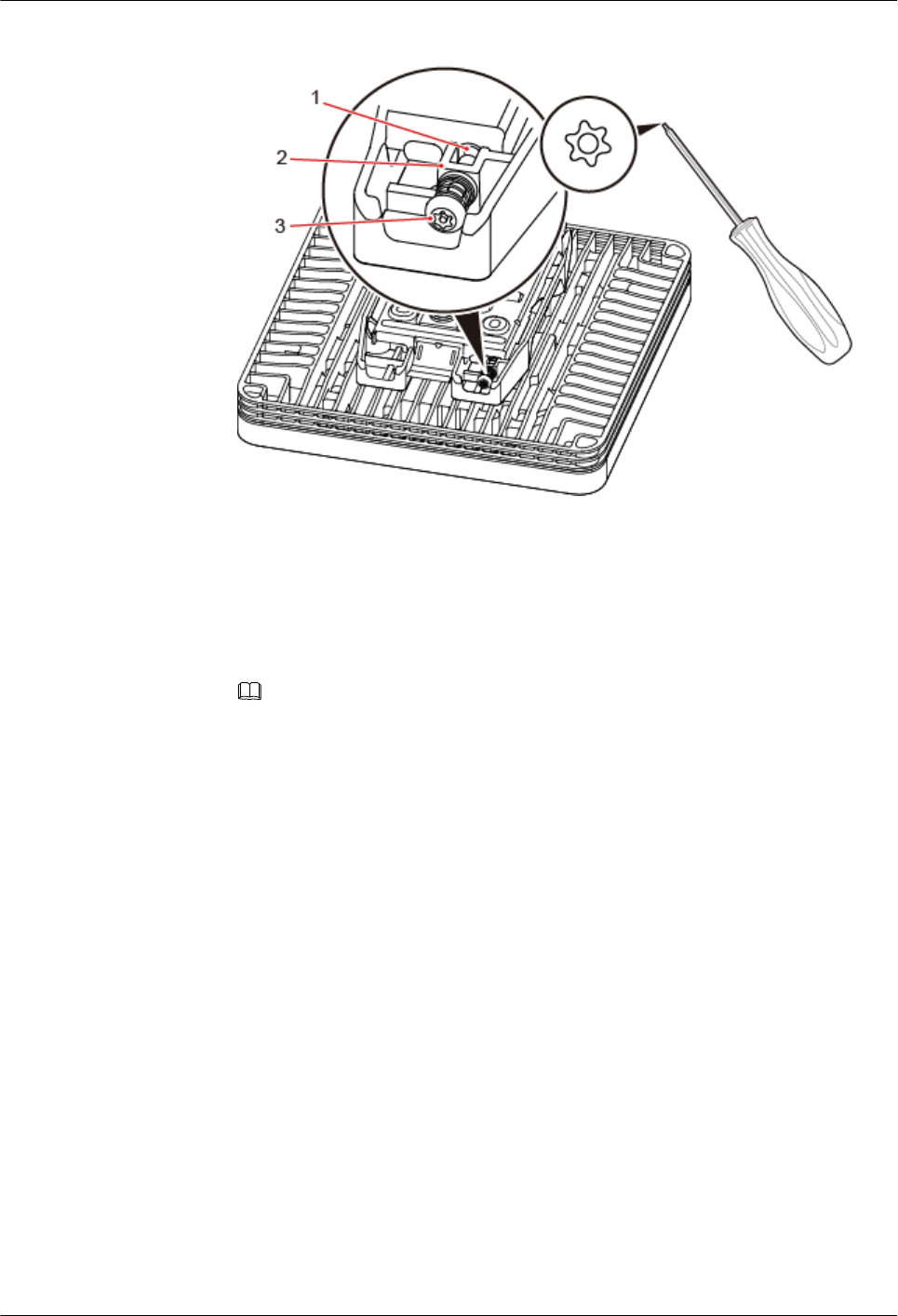
Figure 8-19 Locking the protection screw
(1) M4 threaded hole (2) Hole for self-tapping screws (3) Quincunx screw
lInstallation on an overall suspended ceiling
This installation mode applies when the suspended ceiling (for example, made of plaster
board) cannot be removed.
a. Determine the position for installing the pRRU based on the construction blueprint
and the clearance requirements.
NOTE
For details about the clearance requirements, see 8.1.3 Space Requirements.
b. Use a crown saw to drill a hole with a diameter of 60 mm to 65 mm at the
installation position for the pRRU3902/pRRU3911, as shown in Figure 8-20.
DBS3900 LampSite
Installation Guide 8 Installing a pRRU3902 or pRRU3911
Issue 07 (2015-12-30) Huawei Proprietary and Confidential
Copyright © Huawei Technologies Co., Ltd.
122
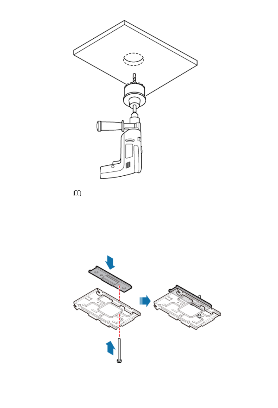
Figure 8-20 Drilling holes by using a crown saw
NOTE
To prevent inhalation or eye contact with dust, take adequate preventive measures when
drilling holes.
c. Use a bolt (M4) to partially connect the mounting bracket and the U-shaped metal
plate, as shown in Figure 8-21.
Figure 8-21 Partially connecting the mounting bracket and the U-shaped metal
plate
DBS3900 LampSite
Installation Guide 8 Installing a pRRU3902 or pRRU3911
Issue 07 (2015-12-30) Huawei Proprietary and Confidential
Copyright © Huawei Technologies Co., Ltd.
123
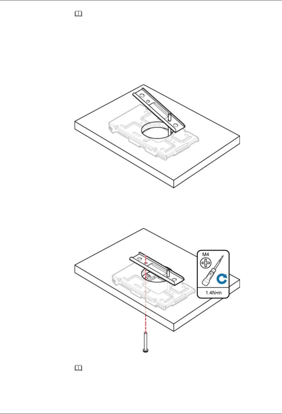
NOTE
The bolt used for installing the pRRU on a suspended ceiling plate depends on the plate thickness:
lThe delivered bolt (M4x35) is used if the plate thickness is less than 25 mm.
lThe delivered bolt (M4X60) is used if the plate thickness ranges from 25 mm to 45 mm.
d. Lead the U-shaped metal plate through the hole on the ceiling, as shown in Figure
8-22.
Figure 8-22 Routing the U-shaped metal plate through the hole on the ceiling
e. Install another bolt with the same length and use a torque screwdriver to torque the
bolts to 1.4 N·m, as shown in Figure 8-23.
Figure 8-23 Assembling the mounting bracket and the U-shaped metal plate
NOTE
If the screws cannot be tightened using a Phillips screwdriver, use a hex key or an electric
screwdriver to assist the installation.
f. Fit the rotation axis on the pRRU into the hooks on the mounting bracket, and then
push the pRRU against the mounting bracket until a click is heard. See Figure 8-24.
DBS3900 LampSite
Installation Guide 8 Installing a pRRU3902 or pRRU3911
Issue 07 (2015-12-30) Huawei Proprietary and Confidential
Copyright © Huawei Technologies Co., Ltd.
124
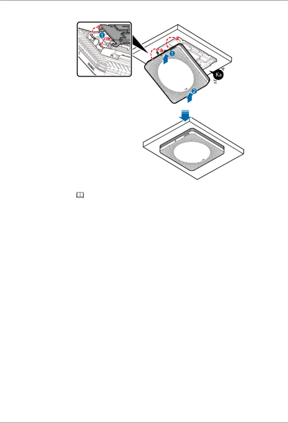
Figure 8-24 Installing a pRRU3902/pRRU3911 on a plate
NOTE
lBefore installing the pRRU, connect one end of the Ethernet cable to the CPRI_E0 port
on pRRU.
lIt is good practice to perform the installation from the side view to promptly align the
hooks with the rotation axis.
g. Use T20 with hole screwdriver to lock the protection screw on the attachment plate.
See Figure 8-25.
The protection screw protects the pRRU from being removed and must be locked if
required.
DBS3900 LampSite
Installation Guide 8 Installing a pRRU3902 or pRRU3911
Issue 07 (2015-12-30) Huawei Proprietary and Confidential
Copyright © Huawei Technologies Co., Ltd.
125
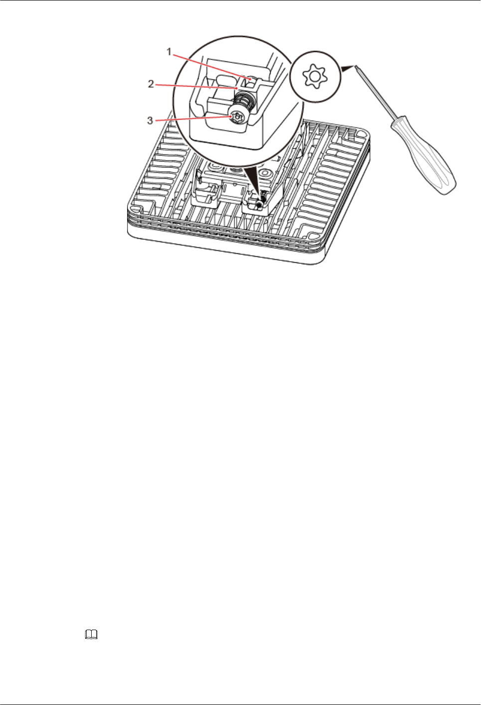
Figure 8-25 Locking the protection screw
(1) M4 threaded hole (2) Hole for self-tapping screws (3) Quincunx screw
----End
8.3.5 Installing a pRRU3902 or pRRU3911 on a Keel
This section describes how to install a pRRU3901 on a keel. If a suspended ceiling plate
cannot bear the pRRU3902/pRRU3911, the pRRU3902/pRRU3911 can be installed on the
keel on the ceiling. The standard keel with a width less than 45 mm, instead of the non-
standard keel, is recommended.
Context
Before installing the pRRU on a keel, ensure that the keel is strong enough to bear the pRRU.
lThe mounting bracket of the pRRU can be installed on the keel of the following
specifications: GBT 11981-2008, JIS A6517-2002, and ASTM C635 C635M-2007. The
installation mode depends on onsite requirements because there are various keels.
lThis section describes the procedure of installing a pRRU3902/pRRU3911 on the keel of
JIS standard used in Japan. The procedure of installing a pRRU on other keels is the
same as that of installing a pRRU on the keel of JIS standard.
The keel used on the ceiling is thin. During installation, fix the mounting kits onto the large
surface instead of the small surface of the keel to prevent distorting the keel.
Procedure
Step 1 Determine the position for installing the pRRU3902/pRRU3911 based on the construction
blueprint and the clearance requirements.
NOTE
For details about the clearance requirements, see 8.1.3 Space Requirements.
Step 2 Place the U-shaped metal plate across the keel. Use a marker to mark the projective positions
of the mounting holes on the suspended ceiling plate, as shown in Figure 8-26.
DBS3900 LampSite
Installation Guide 8 Installing a pRRU3902 or pRRU3911
Issue 07 (2015-12-30) Huawei Proprietary and Confidential
Copyright © Huawei Technologies Co., Ltd.
126
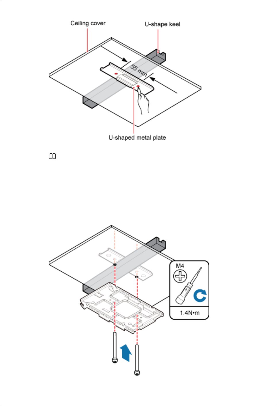
Figure 8-26 Anchor points on the suspended ceiling plate
NOTE
To prevent inhalation or eye contact with dust, take adequate preventive measures when drilling holes.
Step 3 Use a hammer drill to drill holes at the anchor points. You are advised to use the hammer drill
with Ф12 bore.
Step 4 Lead two bolts (M4) through the mounting bracket and the ceiling plate. Use a torque
screwdriver to torque the bolts to 1.4 N•m, as shown in Figure 8-27.
Figure 8-27 Installing the mounting bracket
DBS3900 LampSite
Installation Guide 8 Installing a pRRU3902 or pRRU3911
Issue 07 (2015-12-30) Huawei Proprietary and Confidential
Copyright © Huawei Technologies Co., Ltd.
127
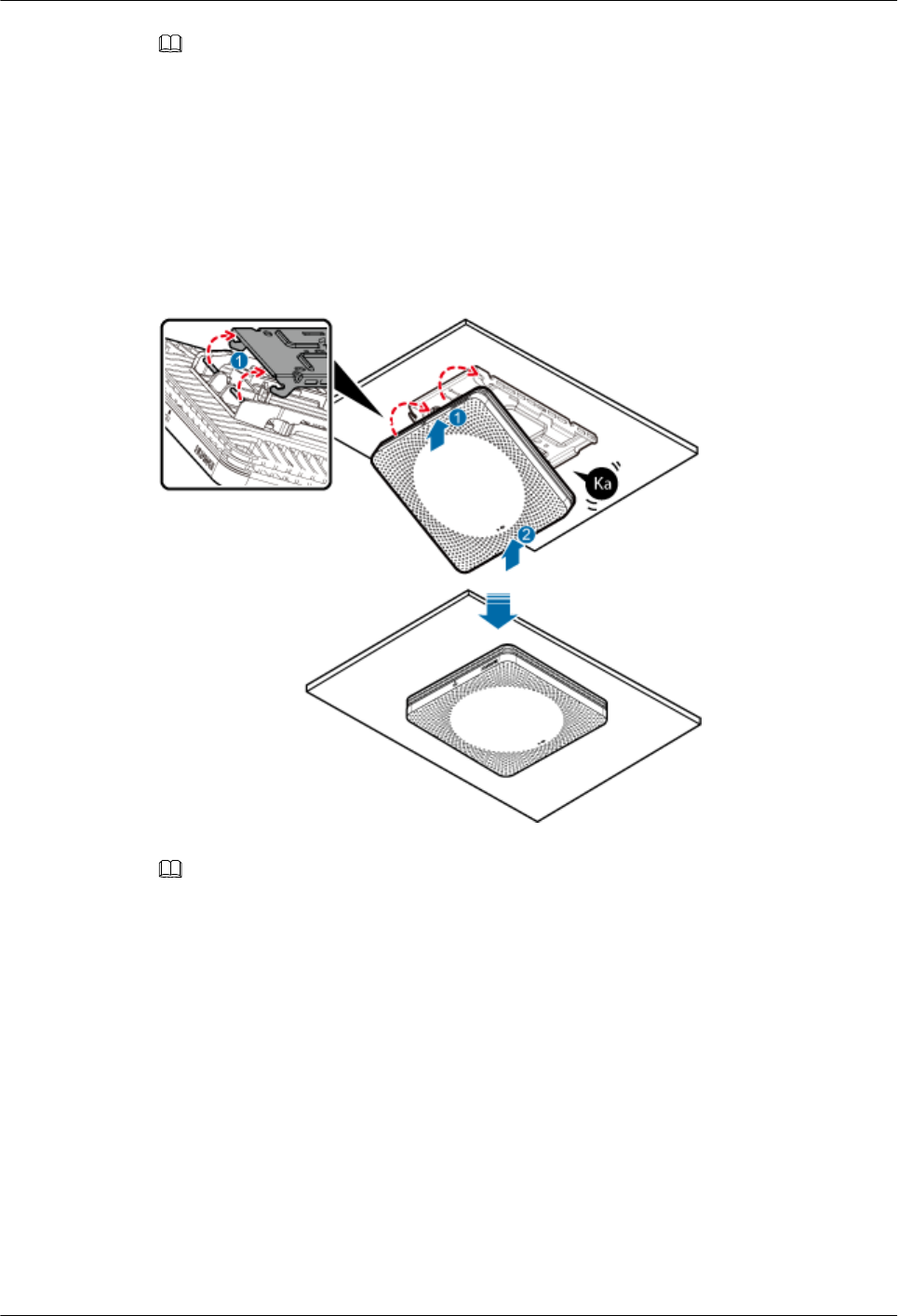
NOTE
lThe bolt used for installing the pRRU on a suspended ceiling plate depends on the plate thickness:
– The delivered bolt (M4 x 35) is used if the plate thickness is less than 25 mm.
– The delivered bolt (M4 x 60) is used if the plate thickness ranges from 25 mm to 45 mm.
lIf the screws cannot be tightened using a Phillips screwdriver, use a hex key or an electric screwdriver to
assist the installation.
Step 5 Fit the rotation axis on the pRRU into the hooks on the mounting bracket, and then push the
pRRU against the mounting bracket until a click is heard. See Figure 8-28.
Figure 8-28 Installing a pRRU3902/pRRU3911 on a keel
NOTE
lBefore installing the pRRU, connect one end of the Ethernet cable to the CPRI_E0 port on pRRU.
lIt is good practice to perform the installation from the side view to promptly align the hooks with the
rotation axis.
Step 6 Optional: Use T20 with hole screwdriver to lock the protection screw on the attachment
plate. See Figure 8-29.
The protection screw protects the pRRU from being removed and must be locked if required.
DBS3900 LampSite
Installation Guide 8 Installing a pRRU3902 or pRRU3911
Issue 07 (2015-12-30) Huawei Proprietary and Confidential
Copyright © Huawei Technologies Co., Ltd.
128
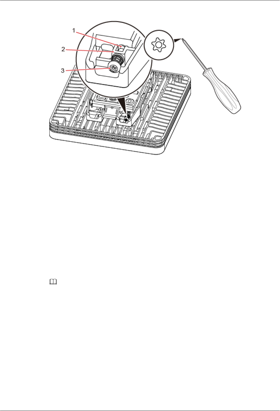
Figure 8-29 Locking the protection screw
(1) M4 threaded hole (2) Hole for self-tapping screws (3) Quincunx screw
----End
8.3.6 Installing a pRRU3902 or pRRU3911 on Steel Hangers
This section describes how to install a pRRU3902/pRRU3911 on steel hangers.
Context
Either M6 or M8 steel hangers can be used for installation.
Procedure
Step 1 Determine the position for installing the pRRU3902/pRRU3911 based on the construction
blueprint and the clearance requirements.
NOTE
For details about the clearance requirements, see 8.1.3 Space Requirements.
Step 2 Install two steel hangers onto the ceiling. A distance of 90 mm must be retained between the
two hangers, as shown in Figure 8-30.
DBS3900 LampSite
Installation Guide 8 Installing a pRRU3902 or pRRU3911
Issue 07 (2015-12-30) Huawei Proprietary and Confidential
Copyright © Huawei Technologies Co., Ltd.
129
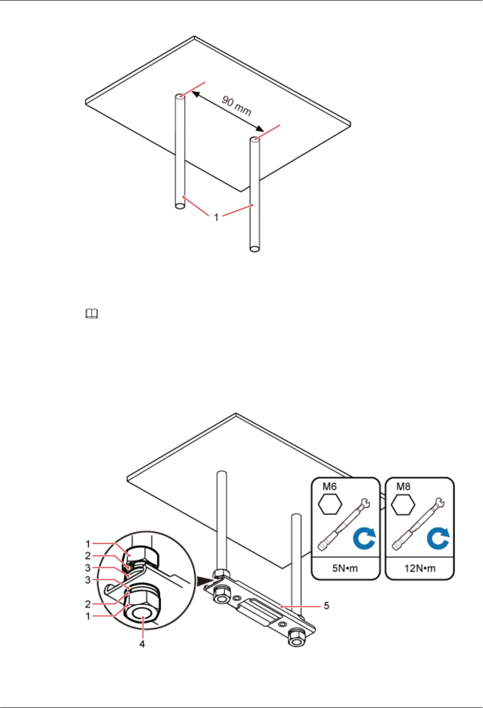
Figure 8-30 Installing steel hangers
Step 3 Install the nuts, spring washers, flat washers, and a U-shaped metal plate onto the steel
hangers, and use a torque wrench to torque the U-shaped metal plate to 5 N•m (on M6 steel
hangers) or 12 N•m (on M8 steel hangers). See Figure 8-31.
NOTE
lThe edge side of the U-shaped metal plate must face upwards.
lThe nuts on the underside of the U-shaped metal plate must be completely fixed into the steel hangers,
and the lower surface of a nut cannot be exposed on the end side of steel hangers, as shown in Figure
8-31.
Figure 8-31 Installing the U-shaped metal plate onto the steel hangers
(1) Nuts (2) Spring washers (3) Flat washers
(4) Steel hangers (5) U-shaped metal plate –
DBS3900 LampSite
Installation Guide 8 Installing a pRRU3902 or pRRU3911
Issue 07 (2015-12-30) Huawei Proprietary and Confidential
Copyright © Huawei Technologies Co., Ltd.
130
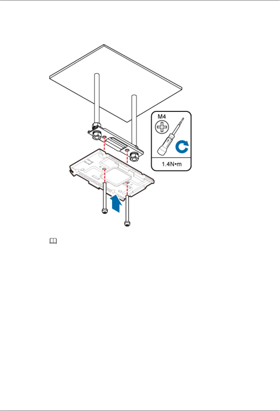
Step 4 Lead two bolts (M4x35) through the mounting bracket and the ceiling plate. Use a torque
screwdriver to torque the bolts to 1.4 N•m, as shown in Figure 8-32.
Figure 8-32 Installing the mounting bracket
NOTE
If the screws cannot be tightened using a Phillips screwdriver, use a hex key or an electric screwdriver to
assist the installation.
Step 5 Fit the rotation axis on the pRRU into the hooks on the mounting bracket, and then push the
pRRU against the mounting bracket until a click is heard. See Figure 8-33.
DBS3900 LampSite
Installation Guide 8 Installing a pRRU3902 or pRRU3911
Issue 07 (2015-12-30) Huawei Proprietary and Confidential
Copyright © Huawei Technologies Co., Ltd.
131
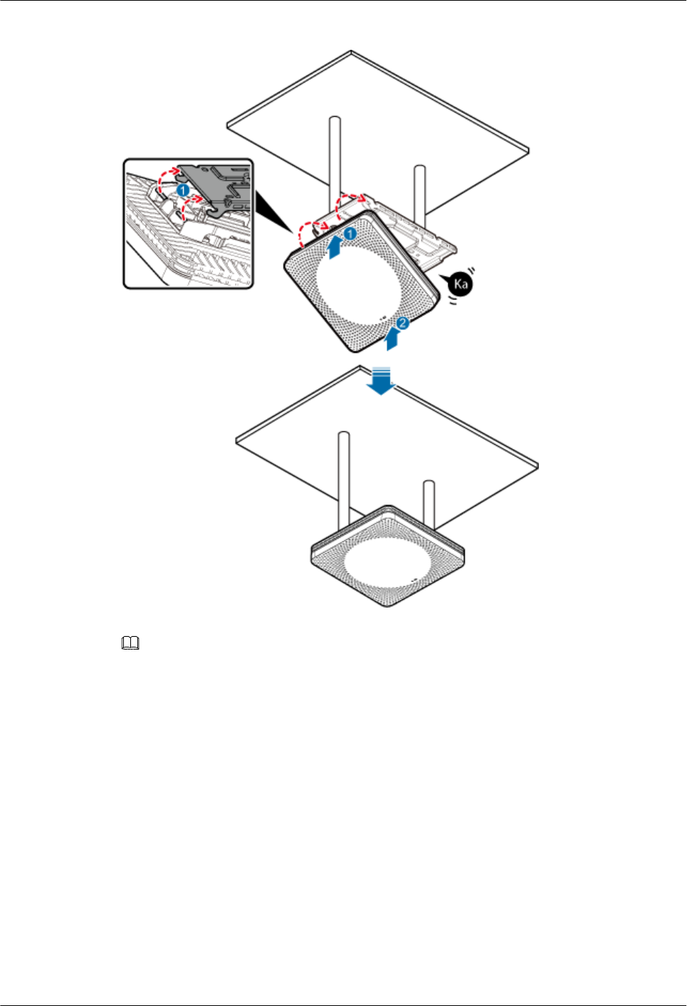
Figure 8-33 Installing a pRRU3902/pRRU3911 on a keel
NOTE
lBefore installing the pRRU, connect one end of the Ethernet cable to the CPRI_E0 port on pRRU.
lIt is good practice to perform the installation from the side view to promptly align the hooks with the
rotation axis.
Step 6 Optional: Use T20 with hole screwdriver to lock the protection screw on the attachment
plate. See Figure 8-34.
The protection screw protects the pRRU from being removed and must be locked if required.
DBS3900 LampSite
Installation Guide 8 Installing a pRRU3902 or pRRU3911
Issue 07 (2015-12-30) Huawei Proprietary and Confidential
Copyright © Huawei Technologies Co., Ltd.
132
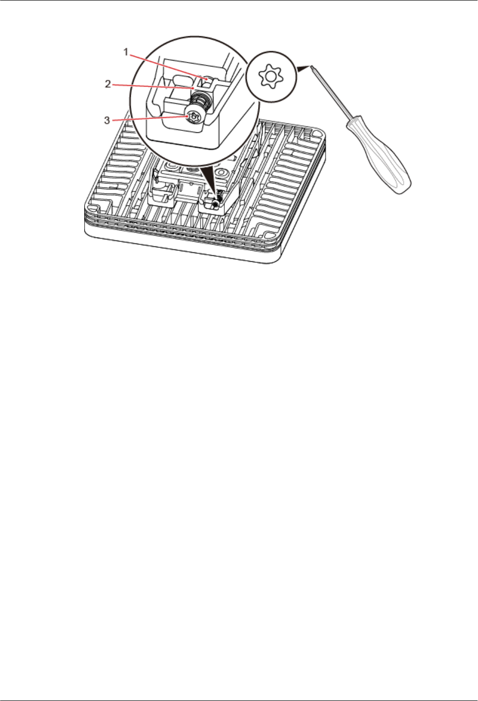
Figure 8-34 Locking the protection screw
(1) M4 threaded hole (2) Hole for self-tapping screws (3) Quincunx screw
----End
8.3.7 Installing the Cabinet
In the outdoor scenario, the pRRU3902 should be installed in the cabinet firstly.
Context
An RF surge protector provides surge protection for the RF ports on pRRU3902, and a PoE
surge protector provides surge protection for the CPRI ports.
One pRRU3902 with internal antenna need to be configured with one PoE surge protector.
One pRRU3902 with external antenna need to be configured with one PoE surge protector
and four RF surge protectors at the same time.
Procedure
Step 1 Install the plate onto the cabinet, as shown in Figure 8-35.
DBS3900 LampSite
Installation Guide 8 Installing a pRRU3902 or pRRU3911
Issue 07 (2015-12-30) Huawei Proprietary and Confidential
Copyright © Huawei Technologies Co., Ltd.
133
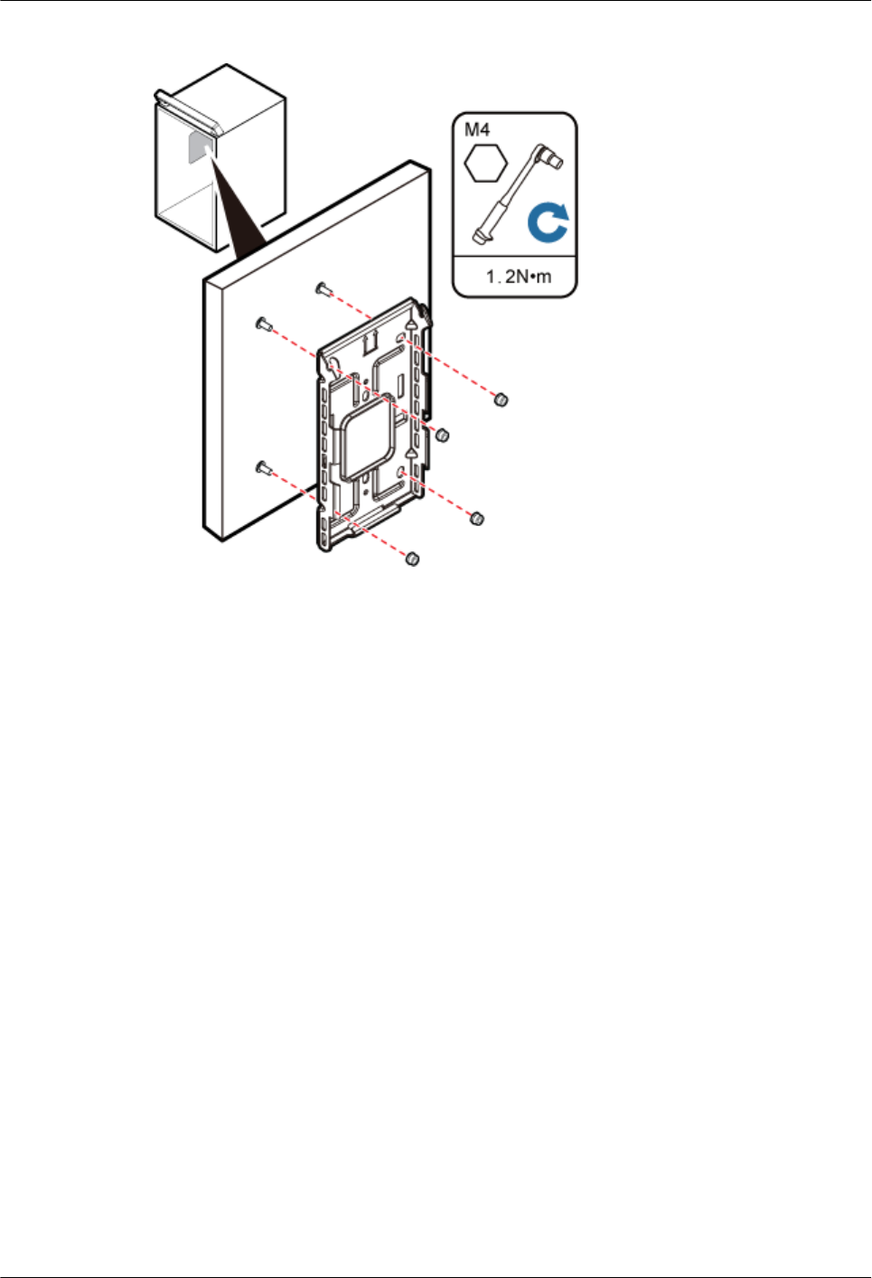
Figure 8-35 Installing the plate onto the cabinet
DBS3900 LampSite
Installation Guide 8 Installing a pRRU3902 or pRRU3911
Issue 07 (2015-12-30) Huawei Proprietary and Confidential
Copyright © Huawei Technologies Co., Ltd.
134
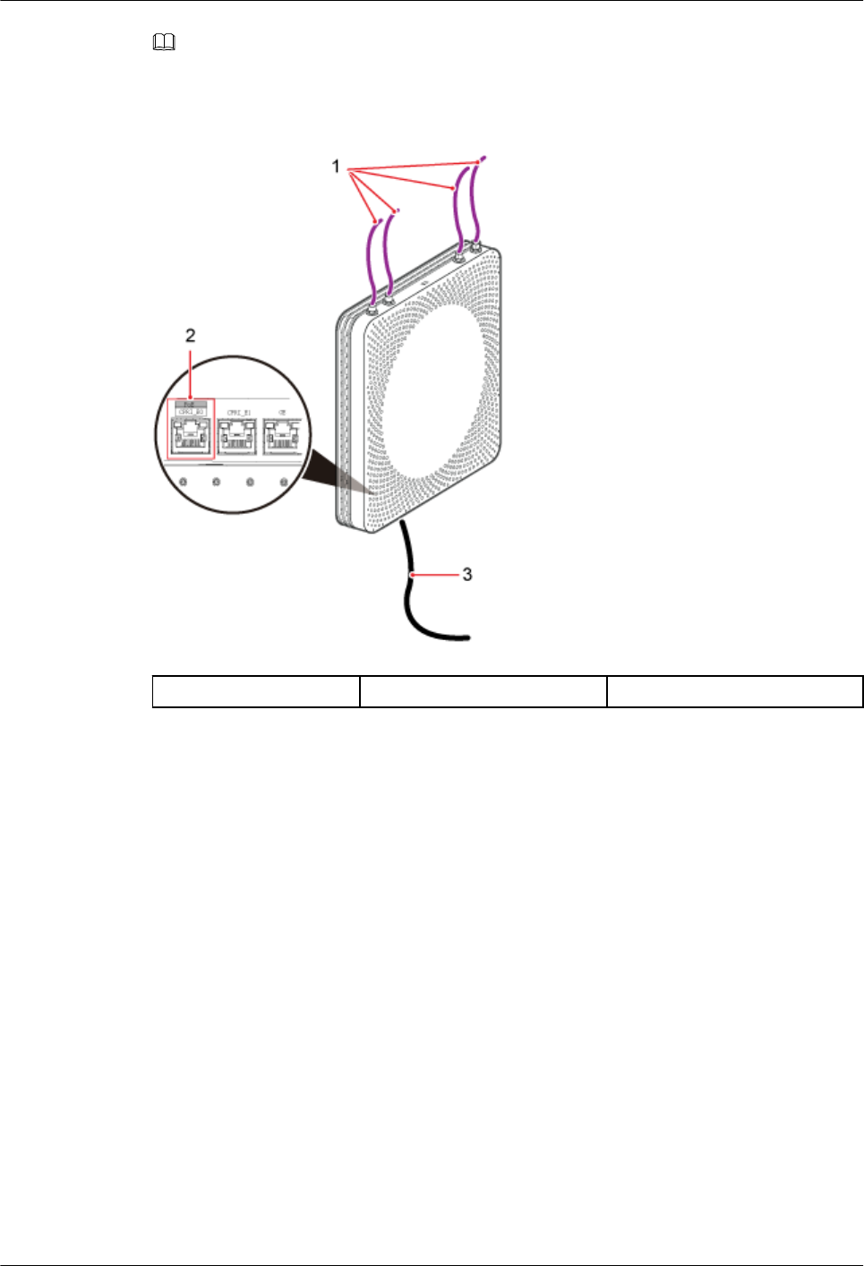
NOTE
Make sure all the cables are installed before installing the plate. For details about installing the cables of
pRRU3902, see Figure 8-36.
Figure 8-36 Installing the pRRU3902 cables
(1) RF Jumper (2) CPRI_E0 port (3) Ethernet Cable
Step 2 Fit the rotation axis on pRRU3902 into the hooks on the mounting bracket, and then push
pRRU3902 against the mounting bracket until a click is heard, as shown in Figure 8-37.
DBS3900 LampSite
Installation Guide 8 Installing a pRRU3902 or pRRU3911
Issue 07 (2015-12-30) Huawei Proprietary and Confidential
Copyright © Huawei Technologies Co., Ltd.
135
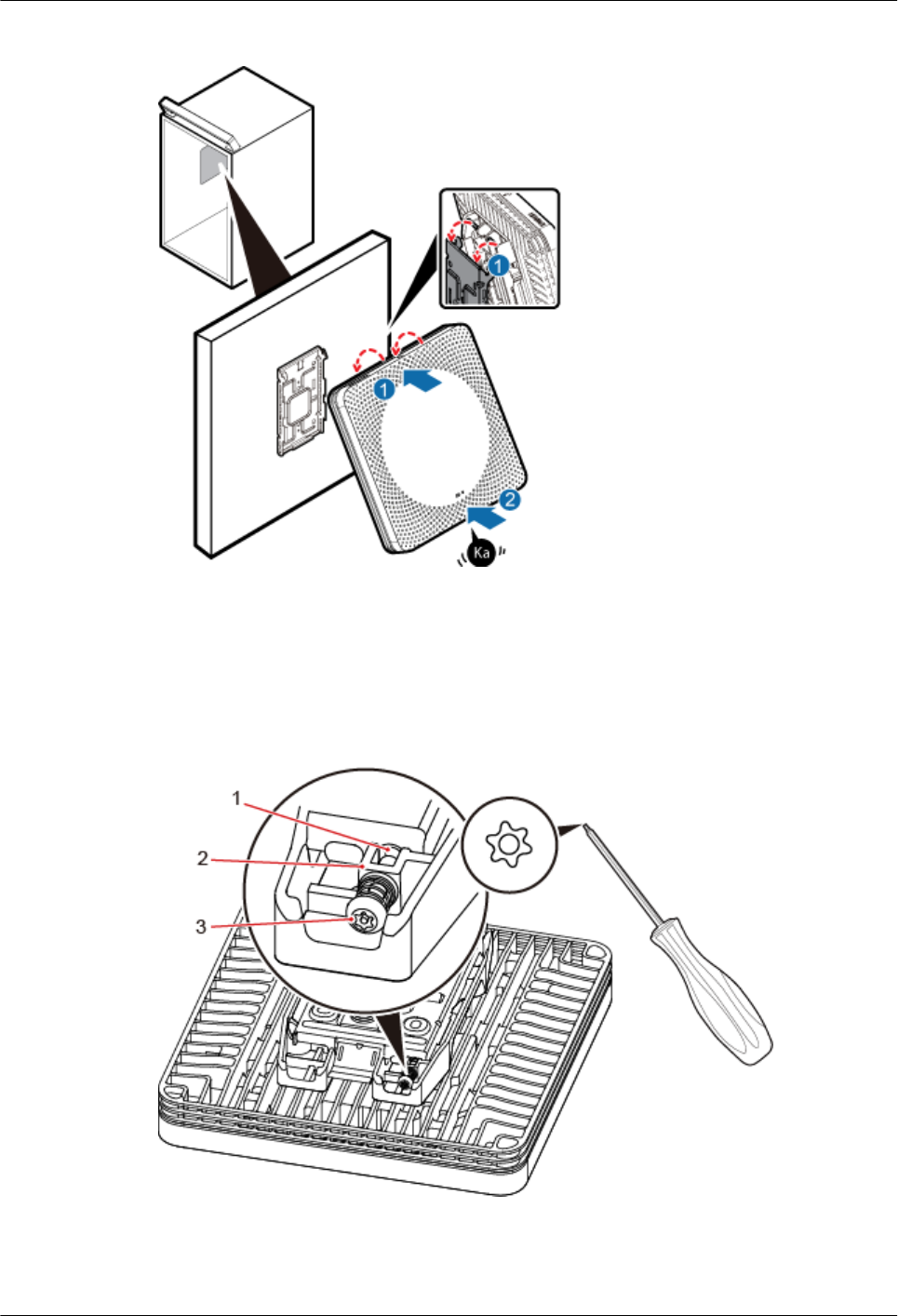
Figure 8-37 Installing a pRRU3902 into the cabinet
Step 3 Optional: Use T20 with hole screwdriver to lock the protection screw on the attachment
plate. See Figure 8-38.
The protection screw protects the pRRU3902 from being removed and must be locked if
required.
Figure 8-38 Locking the protection screw
(1) M4 threaded hole (2) Hole for self-tapping screws (3) Quincunx screw
----End
DBS3900 LampSite
Installation Guide 8 Installing a pRRU3902 or pRRU3911
Issue 07 (2015-12-30) Huawei Proprietary and Confidential
Copyright © Huawei Technologies Co., Ltd.
136

8.4 Installing pRRU3902 or pRRU3911 Cables
This section describes the procedure of installing the pRRU3902/pRRU3911 cables.
8.4.1 Requirements for Cable Layout
Cables must be routed according to the specified cabling requirements to prevent signal
interference.
NOTE
If certain cables listed below are not required, skip the requirements for routing these cables.
General Requirements for Cable Layout
National Standards
lCode for Engineering Design of Generic Cabling System for Building and Campus (GB
50311-2007)
lCode for Engineering Acceptance of Generic Cabling System for Building and Campus
(GB50312-2007).
lSecurity Protection Engineering Technology Specifications (GB 50348-2004)
lCode for Construction and Acceptance of the Electronic Information System Room (GB
50462-2008)
lCode for Quality Acceptance of the Intelligent Building Engineering (GB 50339-2003)
lCode for Quality Acceptance of Electric Engineering Construction in Building (GB
50303-2002)
lTechnical Specification for Construction and Acceptance of Telecommunication Conduit
Engineering (GB 50374-2006)
International Standards
lGeneric Cabling for Customer Premises (ISO/IEC 11801)
lCommercial Building Telecommunications Cabling Standard (EIA/TIA 568)
lCommercial Building Standard for Telecommunication Pathways and Spaces (EIA/TIA
569)
lAdministration Standard for Commercial Telecommunications Infrastructure (EIA/TIA
606)
lGrounding and Bonding Requirements for Telecommunications in Commercial
Buildings (EIA/TIA 607)
lGeneric Cabling Systems for Information Technology (EN 50173)
lCabling Installation for Information Technology (EN 50174)
Bending radius
lThe bending radius of a 1/4'' jumper, a 1/2'' softer jumper, and a 1/2'' common jumper
must be longer than 35 mm, 50 mm, and 127 mm, respectively.
lThe bending radius of a power cable is at least five times the diameter of the cable.
lThe bending radius of a signal cable must be at least five times the diameter of the cable.
Cable binding
DBS3900 LampSite
Installation Guide 8 Installing a pRRU3902 or pRRU3911
Issue 07 (2015-12-30) Huawei Proprietary and Confidential
Copyright © Huawei Technologies Co., Ltd.
137

lCables of the same type are bound together.
lDifferent types of cables must be separately routed with a minimum spacing of 30 mm
and cannot be entangled.
lThe cables are bound tightly and neatly and the sheaths of the cables is intact.
lThe cable ties face the same direction and all cable ties bound at similar positions must
be in a straight line.
lThe extra length of each indoor cable tie must be cut off. A slack of 5 mm is reserved for
each outdoor cable tie before the extra length is cut off. All cut surfaces are without
sharp edges.
lLabels or nameplates are attached to both ends, joints, or turns of cables after they are
installed.
Safety
lThe steel pipe or fire-resistant rigid polyvinyl chloride pipe should be used for the cable
duct or for routing cables. The cross-sectional usage of the cable duct should be 30% to
50% and that of the pipe for routing cables should be 25% to 30%.
lCables are placed away from sharp objects or wall burrs. If these positions are inevitable,
protection pipes are required for the cables.
lCables are routed away from heat sources, or heat-insulation materials are added
between cables and heat sources.
lA clearance is reserved at turns of a cable or the position close to a device, facilitating
cable and device maintenance. The recommended clearance is about 0.1 m.
Requirements for Special Cables
Ethernet Cable
lA maximum of 100 Ethernet cables can be bundled if no PVC pipes are used. If pipes are
used, a maximum of 24 Ethernet cables can be led through a pipe. In this case, ensure
that 1/3 space inside the pipes must be vacant.
lThe point at which an Ethernet cable is bundled must be spaced 400 mm or less from the
Ethernet port on a pRRU.
lFor the pRRU used in the elevator engine room on the rooftop, generator set for the
subway engine, and equipment room with central air conditioning, Ethernet cables must
be led through metallic conduits that are reliably grounded at both ends.
8.4.2 Cable List
This section describes pRRU3902 and pRRU3911 cable connections.
pRRU3902 Cables
Table 8-8 lists pRRU3902 cables.
DBS3900 LampSite
Installation Guide 8 Installing a pRRU3902 or pRRU3911
Issue 07 (2015-12-30) Huawei Proprietary and Confidential
Copyright © Huawei Technologies Co., Ltd.
138
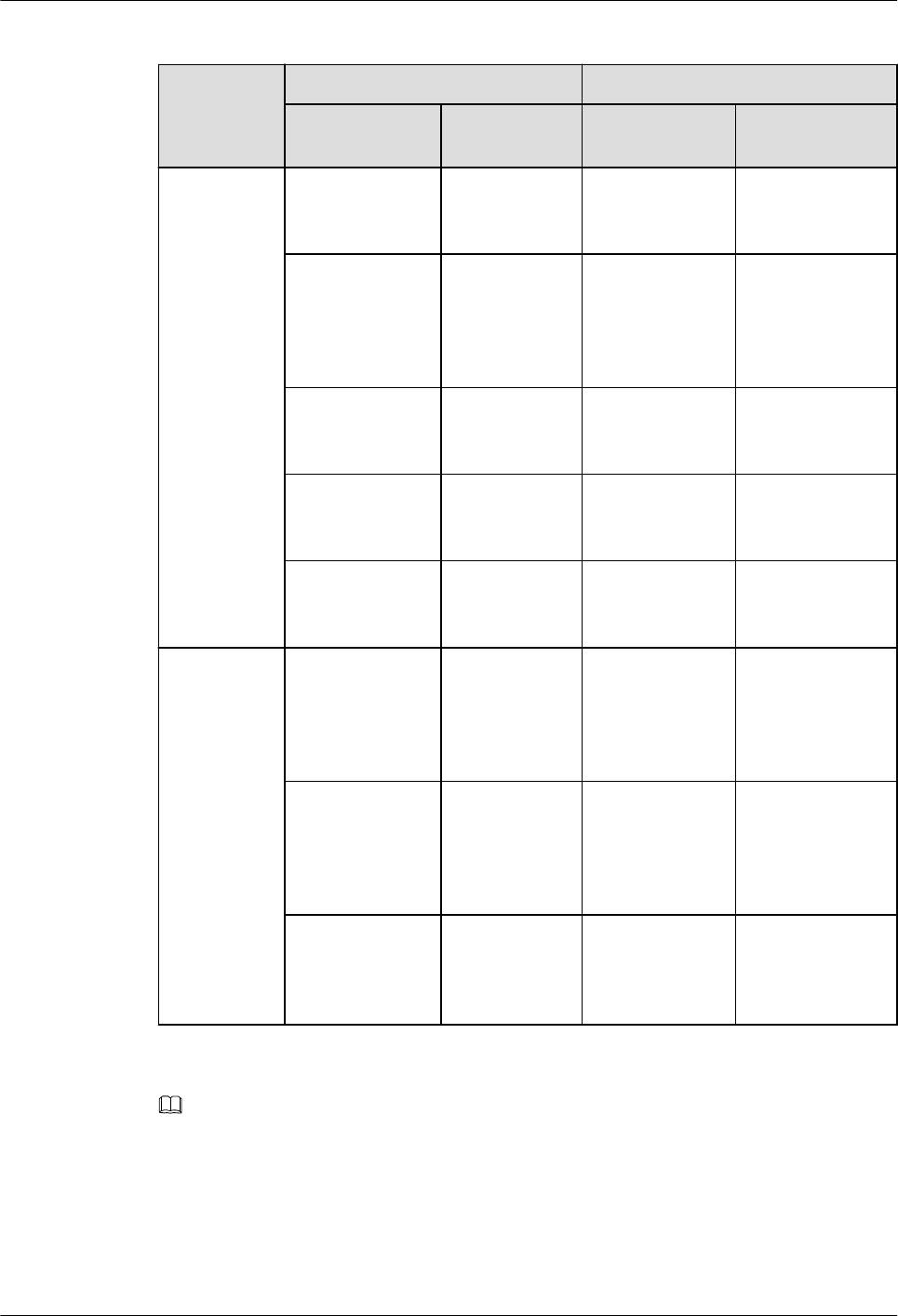
Table 8-8 List of pRRU3902 cables
Cable One End The Other End
Connector Connected
to ...
Connector Connected to ...
Ethernet
Cable
RJ45 connector RHUB/
CPRI_E0~CP
RI_E7 port
RJ45 connector pRRU3902/
CPRI_E0~CPRI_
E1 port
SMA straight
male connector
External
antenna
TX/RX RF
port on
pRRU3902
Based on the
port model of
the antenna
system.
Antenna system
RJ45 connector RHUB/
CPRI_E0~CP
RI_E7 port
RJ45 connector Protect port on
PoE surge
protector 2
RJ45 connector Surge port on
PoE surge
protector 2
RJ45 connector Surge port on
PoE surge
protector 1
RJ45 connector Protect port on
PoE surge
protector 1
RJ45 connector pRRU3902/
CPRI_E0~CPRI_
E1 port
(Optional)
RF Jumper
SMA straight
male connector
External
antenna
TX/RX RF
port on
pRRU3902
Based on the
port model of
the antenna
system.
Antenna system
SMA straight
male connector
External
antenna
TX/RX RF
port on
pRRU3902
SMA straight
male connector
Protect port on
RF surge
protector
SMA straight
male connector
Surge port on
RF surge
protector
Based on the
port model of
the antenna
system.
Antenna system
NOTE
The Extender can be used to lengthen the distance between the RHUB and the pRRU3902 connected using
the Ethernet cable. If the Extender is used, the Ethernet cable is divided into two parts, one between the
RHUB and the Extender and the other between the Extender and the pRRU3902.
pRRU3911 Cables
Table 8-9 lists pRRU3911 cables.
DBS3900 LampSite
Installation Guide 8 Installing a pRRU3902 or pRRU3911
Issue 07 (2015-12-30) Huawei Proprietary and Confidential
Copyright © Huawei Technologies Co., Ltd.
139
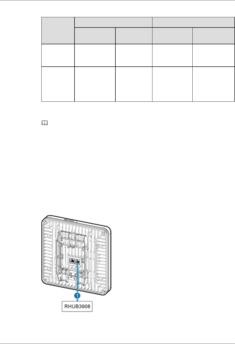
Table 8-9 List of pRRU3911 cables
Cable One End The Other End
Connector Connected
to ...
Connector Connected to ...
Ethernet
Cable
RJ45 connector RHUB/
CPRI_E0~CP
RI_E7 port
RJ45 connector pRRU3911/
CPRI_E0~CPRI_
E1 port
(Optional)
RF Jumper
SMA straight
male connector
External
antenna
TX/RX RF
port on
pRRU3911
Based on the
port model of
the antenna
system
Antenna system
NOTE
The Extender can be used to lengthen the distance between the RHUB and the pRRU3911 connected using
the Ethernet cable. If the Extender is used, the Ethernet cable is divided into two parts, one between the
RHUB and the Extender and the other between the Extender and the pRRU3911.
8.4.3 Cable Connections
This section describes the cable connections for a single pRRU3902 or pRRU3911.
pRRU3902 (Indoor)
Figure 8-39 shows the cable connection of pRRU3902 with internal antenna.
Figure 8-39 pRRU3902 cable connection (1)
(1) Ethernet cable –
DBS3900 LampSite
Installation Guide 8 Installing a pRRU3902 or pRRU3911
Issue 07 (2015-12-30) Huawei Proprietary and Confidential
Copyright © Huawei Technologies Co., Ltd.
140
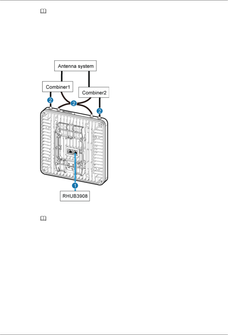
NOTE
The Extender can be used to lengthen the distance between the RHUB and the pRRU3902 connected
using the Ethernet cable. If the Extender is used, the Ethernet cable is divided into two parts, one
between the RHUB and the Extender and the other between the Extender and the pRRU3902.
Figure 8-40 shows the cable connection when the pRRU3902 supporting external antennas.
Figure 8-40 pRRU3902 cable connection (2)
(1) Ethernet cable (2) RF jumper
NOTE
The Extender can be used to lengthen the distance between the RHUB and the pRRU3902 connected
using the Ethernet cable. If the Extender is used, the Ethernet cable is divided into two parts, one
between the RHUB and the Extender and the other between the Extender and the pRRU3902.
pRRU3902 (Outdoor)
Figure 8-41 shows the cable connection of pRRU3902 intalled outside.
DBS3900 LampSite
Installation Guide 8 Installing a pRRU3902 or pRRU3911
Issue 07 (2015-12-30) Huawei Proprietary and Confidential
Copyright © Huawei Technologies Co., Ltd.
141
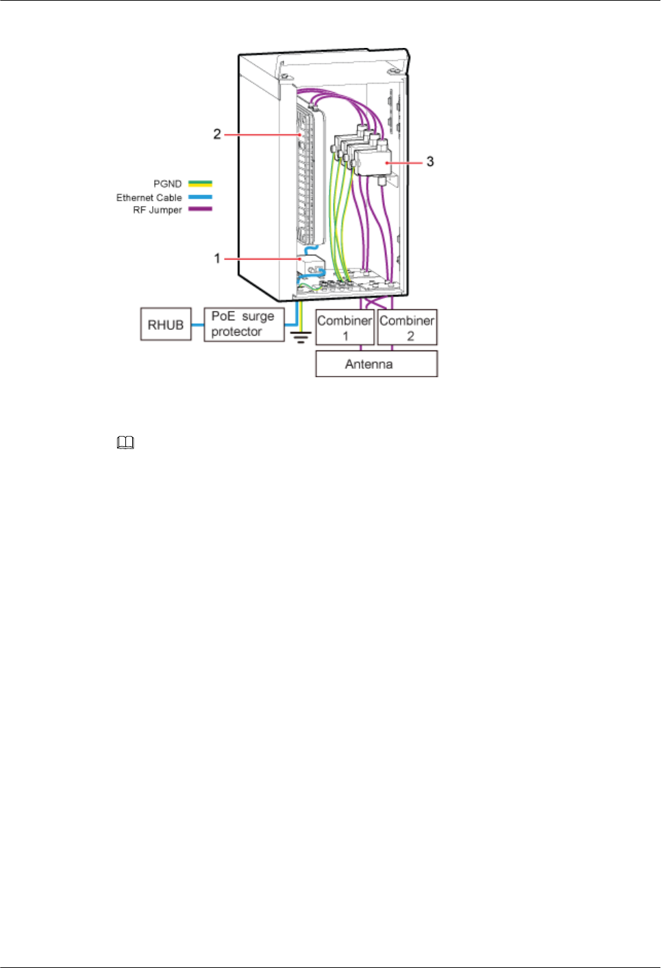
Figure 8-41 pRRU3902 cable connection
(1) PoE surge protector 1 (2) pRRU3902 (3) RF surge protector
NOTE
lThe Extender can be used to lengthen the distance between the RHUB and the pRRU3902 connected
using the Ethernet cable. If the Extender is used, the Ethernet cable is divided into two parts, one
among the RHUB, PoE surge protector 2, PoE surge protector 3, Extender and the other among
Extender, PoE surge protector 4, PoE surge protector 1, pRRU3902.
lFor details about installation of the PoE surge protector and cables, see 10 (Optional) Installing the
PoE Surge Protector and Cables.
lFor details about installation of the RF surge protector and cables, see 11 (Optional) Installing the
RF Surge Protector and Cables.
pRRU3911
Figure 8-42 shows the cable connections of pRRU3911 with internal antenna.
DBS3900 LampSite
Installation Guide 8 Installing a pRRU3902 or pRRU3911
Issue 07 (2015-12-30) Huawei Proprietary and Confidential
Copyright © Huawei Technologies Co., Ltd.
142
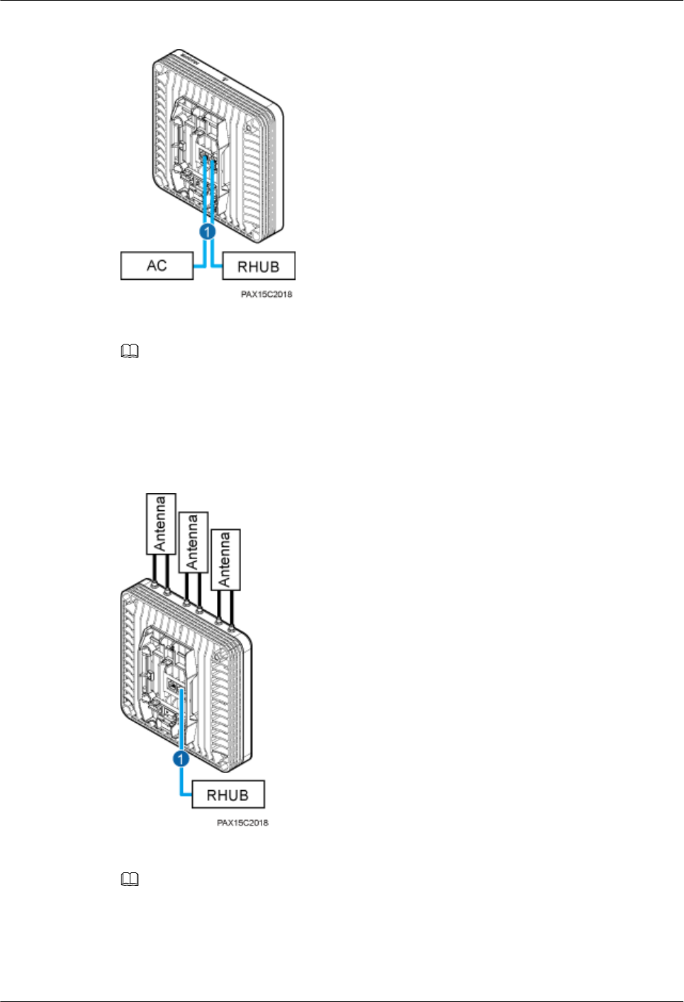
Figure 8-42 pRRU3911 cable connection (1)
(1) Ethernet cable
NOTE
The Extender can be used to lengthen the distance between the RHUB and the pRRU3911 connected
using the Ethernet cable. If the Extender is used, the Ethernet cable is divided into two parts, one
between the RHUB and the Extender and the other between the Extender and the pRRU3911.
Figure 8-43 shows the cable connections of pRRU3911 with external antenna.
Figure 8-43 pRRU3911 cable connection (2)
(1) Ethernet cable
NOTE
The Extender can be used to lengthen the distance between the RHUB and the pRRU3911 connected
using the Ethernet cable. If the Extender is used, the Ethernet cable is divided into two parts, one
between the RHUB and the Extender and the other between the Extender and the pRRU3911.
DBS3900 LampSite
Installation Guide 8 Installing a pRRU3902 or pRRU3911
Issue 07 (2015-12-30) Huawei Proprietary and Confidential
Copyright © Huawei Technologies Co., Ltd.
143
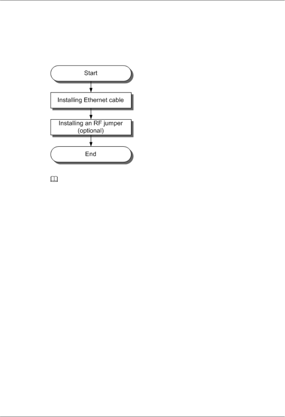
8.4.4 Cable Installation Process
This section describes the process of installing pRRU3902/pRRU3911 cables.
Figure 8-44 shows the process of installing pRRU cables.
Figure 8-44 cable installation process
NOTE
Only the pRRU3902 using external antennas requires RF jumpers, and the pRRU3911 requires no RF
jumpers.
8.4.5 Installing a pRRU3902 Ethernet Cable
This section describes how to install an Ethernet cable.
Prerequisites
lThe Ethernet cable must be of Category 5e (enhanced) or higher. In addition, its cross-
sectional area must be 24 AWG or larger and frame spread rating must be CM or higher.
lThe Ethernet cables can be straight-through cables.
lWith the internal PoE module providing power, the maximum length of an Ethernet
cable is 100 m. With the Extender, the distance of the pRRU3901 and RHUB can be
extended by the Extender up to a total distance of 200 m.
lEthernet cables are not delivered, and they must be prepared onsite. You need to use a
network cable tester to test the Ethernet cable connection.
Context
The Ethernet cable has the following functions:
lProvides power supply for the pRRU3902 when the cable connects the CPRI_E0 port on
the pRRU3902 to the RHUB.
lTransmits CPRI signals between an RHUB and a pRRU3902.
For details about the cable connections in the different scenarios, see 8.4.3 Cable
Connections. The Ethernet cable connections between RHUB and pRRUs are the same. The
following section describes the connections between RHUB-Extender-pRRU3902 as an
example.
DBS3900 LampSite
Installation Guide 8 Installing a pRRU3902 or pRRU3911
Issue 07 (2015-12-30) Huawei Proprietary and Confidential
Copyright © Huawei Technologies Co., Ltd.
144

In the outdoor scenario, PoE surge protector is needed to provide surge protection for the
Ethernet ports. For details about the installation of PoE surge protector, see 10 (Optional)
Installing the PoE Surge Protector and Cables.
Procedure
Step 1 Make the Ethernet cables.
1. Assemble an RJ45 connector and an Ethernet cable by following instructions in
Assembling the Unshielded RJ45 Connector and the Ethernet Cable, Assembling the
Shielded RJ45 Connector and the Ethernet Cable.
NOTE
– Follow pin assignment instructions described in section Ethernet Cable in DBS3900 LampSite
Hardware Description to assemble the RJ45 connector and the Ethernet cable. Otherwise, the
transmission signal quality deteriorates and CPRI links may be disconnected.
– The pRRU3902 supports both unshielded and shielded Ethernet cables. It is good practice to
use unshielded Ethernet cables.
2. Check whether the made RJ45 connector is qualified by following instructions in
Checking the Appearance of Metal Contact Strips.
3. To complete the assembly of the other end, repeat Step 1.1 and Step 1.2.
4. Check whether the touch points on the connectors at both ends are normally conducted
and well contacted and whether the connections are correct by following instructions in
Testing the Connection of Assembled Cables of Installation Reference.
Step 2 Install an Ethernet cable between an RHUB and a pRRU3902.
Step 3 Connect the RJ45 connector at one end of the Ethernet cable to the CPRI_E0 port on the
pRRU3902 panel.
Step 4 Optional: Connect the RJ45 connector at the other end of the Ethernet cable to the output
port of the Extender. Then, connect the RJ45 connector at one end of another Ethernet cable
to the input port of the Extender.
In this scene, the Ethernet cable is divided into two parts, one between the RHUB and the
Extender and the other between the Extender and the pRRU3902.
Step 5 Connect the RJ45 connector at the other end of the Ethernet cable to any port ranging from
CPRI_E0 to CPRI_E7 on the RHUB panel based on the engineering design, as shown in
Figure 8-45.
DBS3900 LampSite
Installation Guide 8 Installing a pRRU3902 or pRRU3911
Issue 07 (2015-12-30) Huawei Proprietary and Confidential
Copyright © Huawei Technologies Co., Ltd.
145
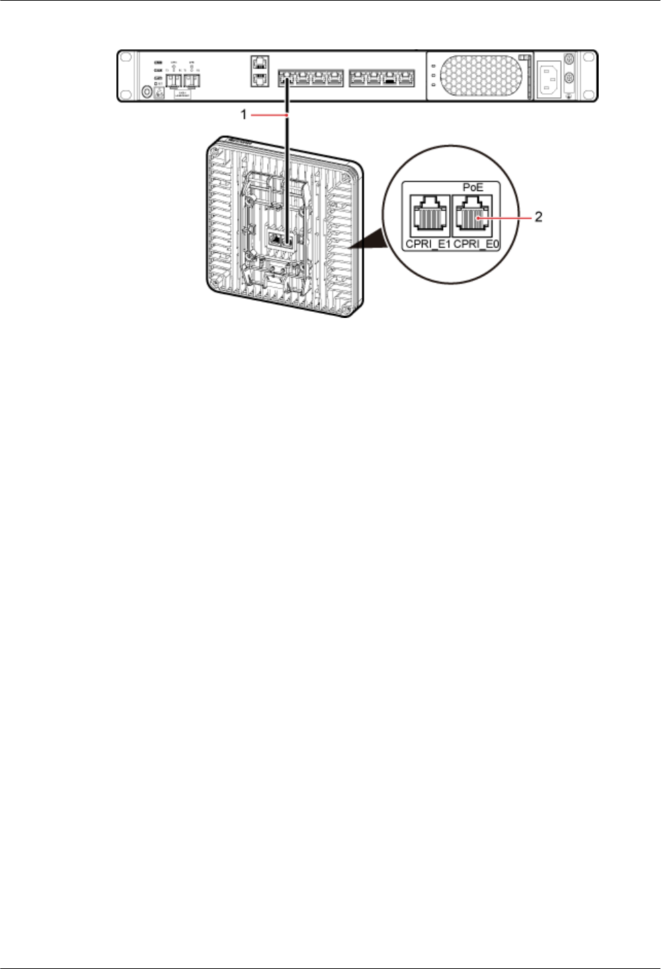
Figure 8-45 Installing an Ethernet cable
(1) Ethernet cable (2) CPRI_E0 port on the pRRU3902
----End
Follow-up Procedure
1. Route the cable, and then use a cable tie to bind the cable. For details, see 8.4.1
Requirements for Cable Layout.
2. Label the installed cable. For details, see section 14.4 Attaching an L-Shaped Label.
8.4.6 Installing a pRRU3911 Ethernet Cable
This section describes how to install a pRRU3911 Ethernet cable.
Prerequisites
lThe Ethernet cable must be of Category 5e (enhanced) or higher. In addition, its cross-
sectional area must be 24 AWG or larger and frame spread rating must be CM or higher.
lThe Ethernet cables can be straight-through cables.
lWith the internal PoE module providing power, the maximum length of an Ethernet
cable is 100 m. With the Extender, the distance of the pRRU3911 and RHUB can be
extended by the Extender up to a total distance of 200 m.
lEthernet cables are not delivered, and they must be prepared onsite. You need to use a
network cable tester to test the Ethernet cable connection.
Context
The Ethernet cable has the following functions:
lProvides power supply for the pRRU3911 when the cable connects the CPRI_E0 port on
the pRRU3911 to the RHUB.
lTransmits CPRI signals between an RHUB and a pRRU3911.
DBS3900 LampSite
Installation Guide 8 Installing a pRRU3902 or pRRU3911
Issue 07 (2015-12-30) Huawei Proprietary and Confidential
Copyright © Huawei Technologies Co., Ltd.
146
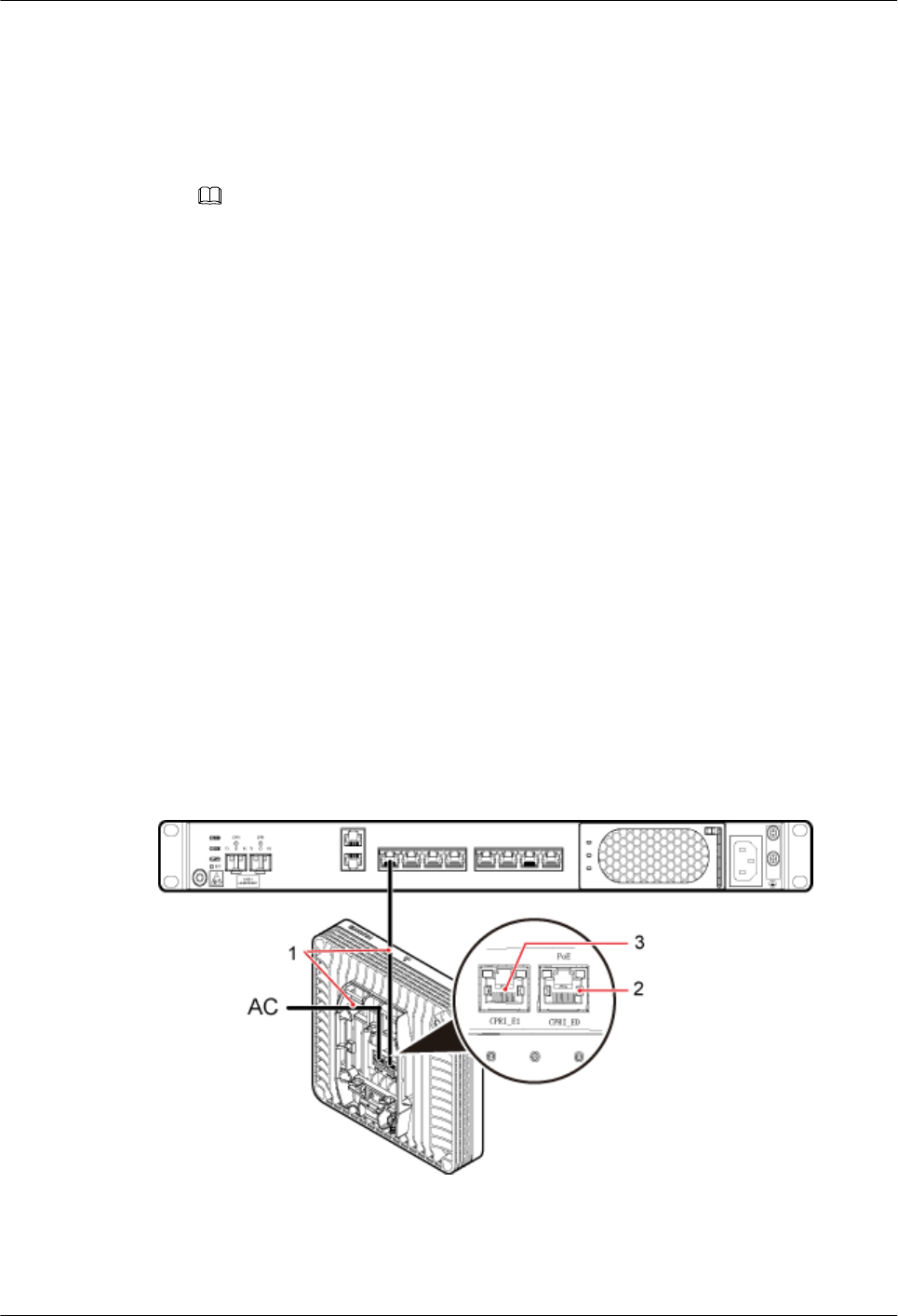
Procedure
Step 1 Make the Ethernet cables.
1. Assemble an RJ45 connector and an Ethernet cable by following instructions in
Assembling the Unshielded RJ45 Connector and the Ethernet Cable, Assembling the
Shielded RJ45 Connector and the Ethernet Cable.
NOTE
Follow pin assignment instructions described in section Ethernet Cable in DBS3900 LampSite
Hardware Description to assemble the RJ45 connector and the Ethernet cable. Otherwise, the
transmission signal quality deteriorates and CPRI links may be disconnected.
2. Check whether the made RJ45 connector is qualified by following instructions in
Checking the Appearance of Metal Contact Strips.
3. To complete the assembly of the other end, repeat Step 1.1 and Step 1.2.
4. Check whether the touch points on the connectors at both ends are normally conducted
and well contacted and whether the connections are correct by following instructions in
Testing the Connection of Assembled Cables of Installation Reference.
Step 2 Install an Ethernet cable between an RHUB and a pRRU3911.
Step 3 Connect the RJ45 connector at one end of the Ethernet cable to the CPRI_E0 port on the
pRRU3911 panel.
Step 4 Optional: Connect the RJ45 connector at the other end of the Ethernet cable to the output
port of the Extender. Then, connect the RJ45 connector at one end of another Ethernet cable
to the input port of the Extender.
In this scene, the Ethernet cable is divided into two parts, one between the RHUB and the
Extender and the other between the Extender and the pRRU3911.
Step 5 Connect the RJ45 connector at the other end of the Ethernet cable to any port ranging from
CPRI_E0 to CPRI_E7 on the RHUB panel based on the engineering design, as shown in
Figure 8-46.
Figure 8-46 Installing an Ethernet cable
(1) Ethernet cable (2) CPRI_E0 port (3) CPRI_E1 port
Step 6 Optional: If the Wi-Fi daughter board is used, install the Ethernet cable to connect the AC
and the pRRU3911.
DBS3900 LampSite
Installation Guide 8 Installing a pRRU3902 or pRRU3911
Issue 07 (2015-12-30) Huawei Proprietary and Confidential
Copyright © Huawei Technologies Co., Ltd.
147

1. Remove the dustproof cap from the CPRI_E1 port.
2. Connect an RJ45 connector of the Ethernet cable to the CPRI_E1 port on the pRRU3911.
3. Connect the other RJ45 connector of the Ethernet cable to the transmission port on the
AC based on the engineering design requirements. See Figure 8-46.
----End
8.4.7 Installing a pRRU3902 RF Jumper (Optional)
The RF Jumpers transmit radio frequency signals between pRRU3902 with external antennas
and the combiners. Only the pRRU3902 using external antennas can be configured with an
RF Jumper.
Context
lAn RF jumpers delivered is 50 cm at most.
lIf the RF jumper is provided by the customer, the jumper must not be lower than the
RG316 specifications. In addition, the jumpers can be used after they are checked by
Huawei engineers.
lpRRU3902s can be connected to external whip antennas or external remote antennas
(through pRRU3902 RF jumpers). Whip antennas are delivered optionally. RF jumpers
are not delivered.
lFor details about the cable connections in the different scenarios, see 8.4.3 Cable
Connections. The installation of RF jumper cables are the same. The following section
describes the connections between antenna and pRRU3902 in the indoor scenario as an
example.
lIn the outdoor scenario, RF surge protector is needed to provide surge protection for the
RF ports. For details about the installation of RF surge protector, see 11 (Optional)
Installing the RF Surge Protector and Cables.
Procedure
Step 1 Use a torque wrench with a torque of 0.6 N•m to connect the SMA straight male connector on
a jumper to the ANT port on the pRRU3902 panel.
NOTICE
Tighten it with hands, and then use a torque wrench to tighten it with a rotational speed of less
than or equal to 2.4 rpm to tighten it.
Step 2 Connect the type N female connector of the jumper to the type N male connector of the RF
feeder connected to the PORT port of the combiner, as shown as Table 8-10.
DBS3900 LampSite
Installation Guide 8 Installing a pRRU3902 or pRRU3911
Issue 07 (2015-12-30) Huawei Proprietary and Confidential
Copyright © Huawei Technologies Co., Ltd.
148

Table 8-10 Connections of the RF jumper between pRRU3902 and combiners
One End The Other End
Connector Connected to... Connector Connected to...
SMA straight
male connector
pRRU3902/ANT0 RF
port
Type N male
connector
Combiner1/PORT1 or
PORT2 prot
pRRU3902/ANT1 RF
port
Combiner2/PORT1 or
PORT2 prot
pRRU3902/ANT2 RF
port
Combiner1/PORT2 or
PORT2 prot
pRRU3902/ANT3 RF
port
Combiner2/PORT2 or
PORT1 prot
DBS3900 LampSite
Installation Guide 8 Installing a pRRU3902 or pRRU3911
Issue 07 (2015-12-30) Huawei Proprietary and Confidential
Copyright © Huawei Technologies Co., Ltd.
149
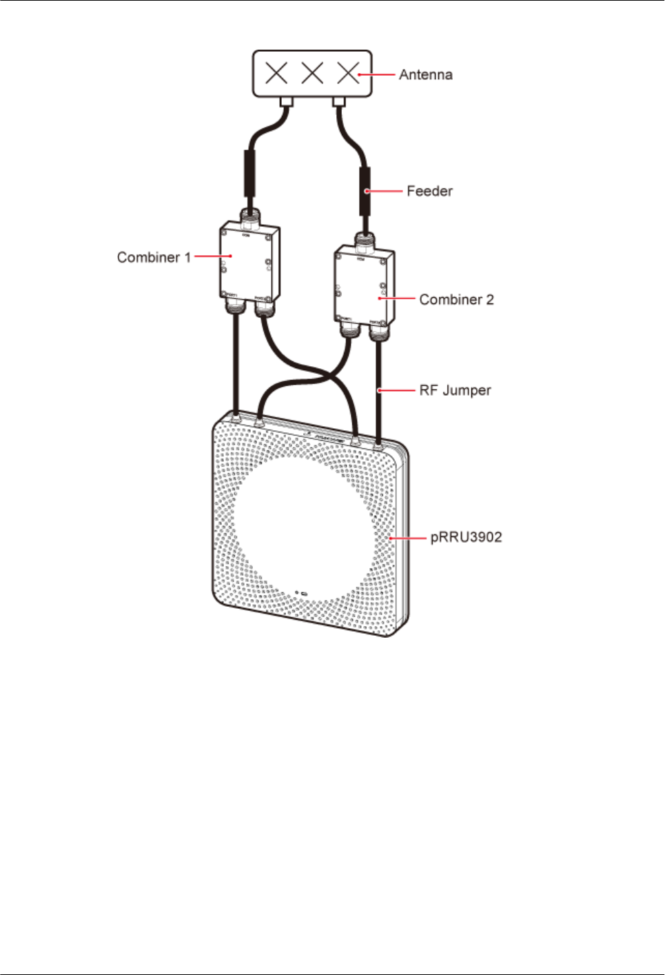
Figure 8-47 Installing jumpers between the pRRU3902 and Combiners
----End
Follow-up Procedure
1. Route the cable, and then use a cable tie to bind the cable. For details, see 8.4.1
Requirements for Cable Layout.
2. Label the installed cable. For details, see section 14.4 Attaching an L-Shaped Label.
8.4.8 Installing a pRRU3911 RF Jumper (Optional)
The RF Jumpers transmit radio frequency signals between pRRU3911 and the external
antennas. Only the pRRU3911 using external antennas can be configured with an RF Jumper.
Context
lAn RF jumpers delivered is 50 cm at most.
DBS3900 LampSite
Installation Guide 8 Installing a pRRU3902 or pRRU3911
Issue 07 (2015-12-30) Huawei Proprietary and Confidential
Copyright © Huawei Technologies Co., Ltd.
150
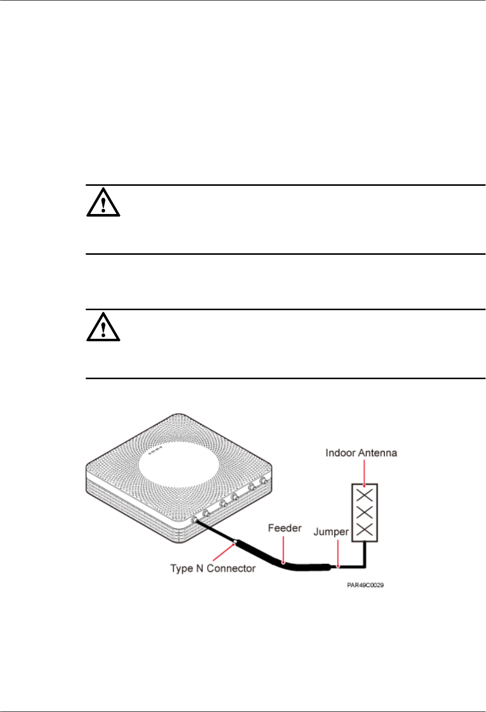
lIf the RF jumper is provided by the customer, the jumper must not be lower than the
RG316 specifications. In addition, the jumpers can be used after they are checked by
Huawei engineers.
lpRRU3911s can be connected to external whip antennas or external remote antennas
(through pRRU3911 RF jumpers). Whip antennas are delivered optionally. RF jumpers
are not delivered.
Procedure
Step 1 Use a torque wrench with a torque of 0.6 N•m to connect the SMA straight male connector on
a jumper to the ANT port on the pRRU3902 panel.
NOTICE
Tighten it with hands, and then use a torque wrench to tighten it with a rotational speed of less
than or equal to 2.4 rpm to tighten it.
Step 2 Connect the type N female connector of the jumper to the type N male connector of the RF
feeder connected to the built-in antenna.
NOTICE
Tighten the feeder close to the type N connector to ensure that the jumper is not tightened. In
this way, the connectors on both ends of a jumper are not affected by the external force.
Figure 8-48 Installing jumpers between the pRRU3911 and external antennas
----End
Follow-up Procedure
1. Route the cable, and then use a cable tie to bind the cable. For details, see 8.4.1
Requirements for Cable Layout.
2. Label the installed cable. For details, see section 14.4 Attaching an L-Shaped Label.
DBS3900 LampSite
Installation Guide 8 Installing a pRRU3902 or pRRU3911
Issue 07 (2015-12-30) Huawei Proprietary and Confidential
Copyright © Huawei Technologies Co., Ltd.
151
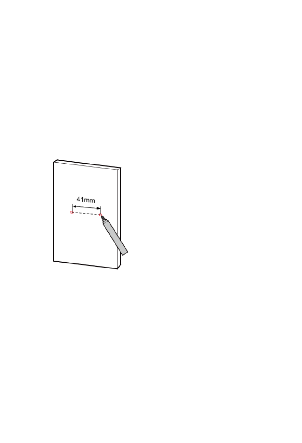
8.5 (Optional) Installing a Combiner
This section describes how to install a combiner. The pRRU3902 using external antennas
must be configured with a combiner.
Context
This section describes how to mount a combiner on a wall as an example. The actual
installation mode depends on actual requirements.
Procedure
Step 1 Use a marker to mark two anchor points according to inter-hole spacing, as shown in Figure
8-49.
Figure 8-49 Marking anchor points
Step 2 Use a hammer drill with φ6 bore to drill holes at the marked anchor points, as shown in
Figure 8-50. Use a vacuum cleaner to clean the dust inside and around the holes and measure
the distance between them. If they are inaccurately positioned, re-measure and re-drill the
holes. Then, use a rubber mallet to hit a plastic expansion sleeve into each hole.
DBS3900 LampSite
Installation Guide 8 Installing a pRRU3902 or pRRU3911
Issue 07 (2015-12-30) Huawei Proprietary and Confidential
Copyright © Huawei Technologies Co., Ltd.
152
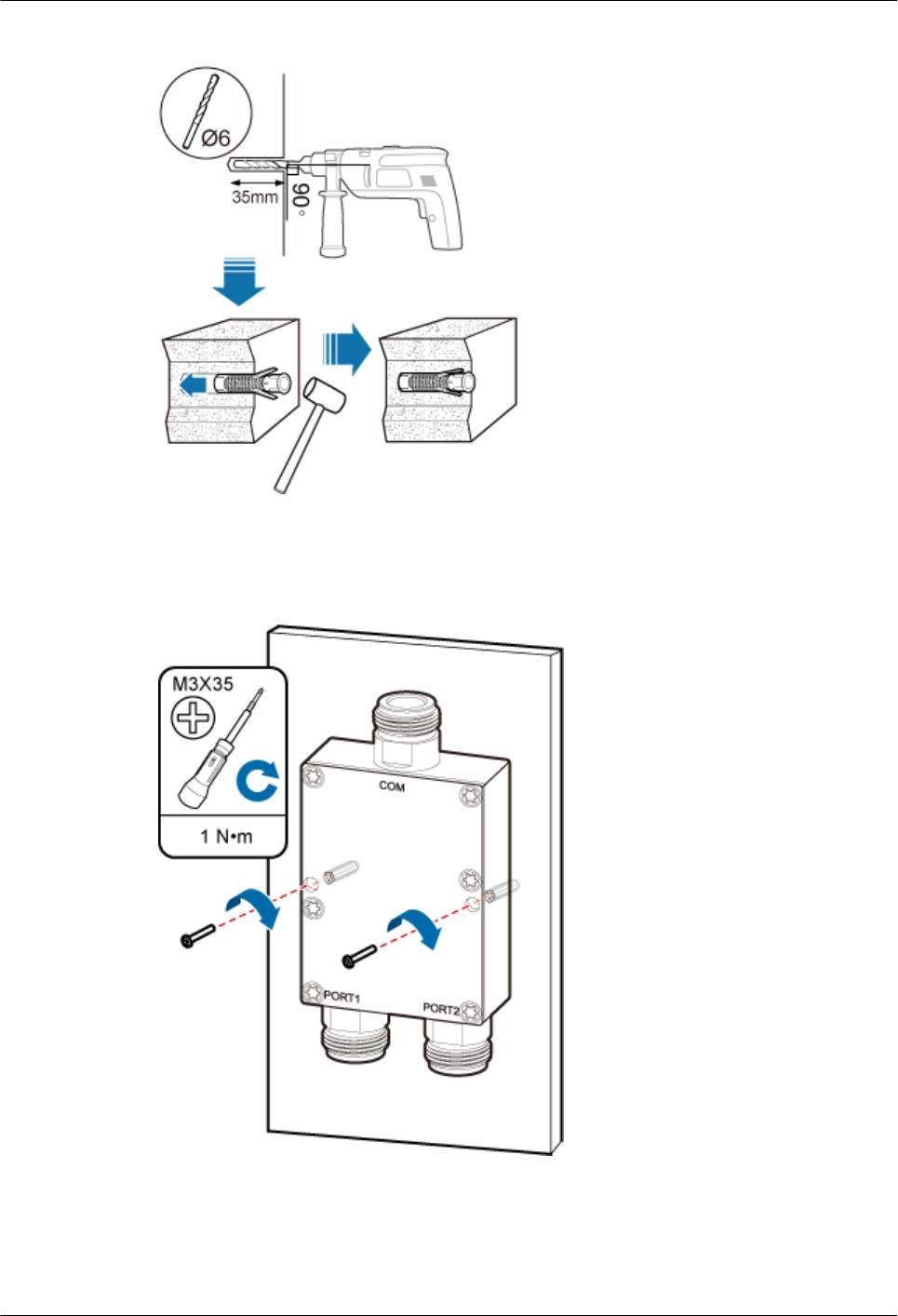
Figure 8-50 Drilling holes and installing expansion bolts
Step 3 Place the Extender in the corresponding position and use an M3 Phillips screwdriver to torque
the screws to 1 N•m, as shown in Figure 8-51.
Figure 8-51 Installing the Extender
----End
DBS3900 LampSite
Installation Guide 8 Installing a pRRU3902 or pRRU3911
Issue 07 (2015-12-30) Huawei Proprietary and Confidential
Copyright © Huawei Technologies Co., Ltd.
153
8.6 Checking the pRRU Hardware Installation
pRRU hardware installation checking includes hardware and cable installation checking.
Table 8-11 lists the hardware installation checking items.
Table 8-11 Hardware installation checking list
No. Item
1 Ensure that the pRRU3902/pRRU3911 is not grouned.
2 The position for each device conforms to the engineering design and meets the
space requirement.
3 Ensure that the pRRU3902/pRRU3911 is properly installed.
4 The surface of the pRRU3902/pRRU3911 is neat and clean. The external paint
is intact. The labels, tags, and nameplates are correct, legible, and complete.
Table 8-12 lists the check items of the signal cable connection.
Table 8-12 Checklist for the signal cable connection
No. Item
1 The connectors of the signal cables must securely connected.
2 The connectors of the signal cables are intact.
3 The signal cables are intact.
4 The cable ties are evenly spaced. The signal cables are bound neatly with cable
ties to proper tightness, and arranged at even intervals in the same direction.
5 The extra length of the cable ties is cut and removed. The cut surfaces of the
indoor cables are smooth and have no sharp edges.
6 The cable layout facilitates maintenance and expansion.
7 Correct and clear labels are attached to both ends of the signal cables.
Table 8-13 lists the checking items for other cable connections.
Table 8-13 Checklist for other cable connections
No. Item
1 The connectors of the other cables must securely connected.
DBS3900 LampSite
Installation Guide 8 Installing a pRRU3902 or pRRU3911
Issue 07 (2015-12-30) Huawei Proprietary and Confidential
Copyright © Huawei Technologies Co., Ltd.
154
No. Item
2 Labels on the cables are legible and bound based on the engineering
requirements. The cables must be bound tightly and neatly. The sheaths of the
cables must not be damaged.
3 Positions for routing the cables must meet requirements of the engineering
design.
8.7 Powering on the pRRU
This section describes the power-on check on the pRRU3902/pRRU3911 after the pRRU
hardware is installed and checked.
Context
After the RHUB and pRRUs are installed and connected to each other, power on them no
matter whether the BBU is installed.
Procedure
Step 1 Power on the pRRU.
The pRRU supports PoE. The RHUB supplies power to the pRRU in PoE mode through the
CPRI_E0 port on the pRRU.
Step 2 Power on the pRRU. Wait 3 to 5 minutes, check the status of the 3GPP indicator on the
pRRU3902 or pRRU3911.
If the 3GPP Indicator... Because... Then...
Blinks white at 4 Hz The pRRU is loading
software, configuring data, or
it is not running.
Wait until the software is
loaded. If the loading is not
completed in five minutes,
power off the pRRU and
check whether the data
configuration file is correct.
After the fault is rectified,
power on the pRRU again.
Blinks white at 0.5 Hz
(on for 1s and off for 1s)
The pRRU is working
properly and does not
transmit power.
Check whether the services
have been configured and
power amplification have
been enabled on the pRRU.
Is steady white The cell is set up and
transmits power properly.
No further action is required.
Is steady orange. There is power input, but the
hardware is faulty.
Power off the pRRU, rectify
the hardware fault, and then
power it on again.
DBS3900 LampSite
Installation Guide 8 Installing a pRRU3902 or pRRU3911
Issue 07 (2015-12-30) Huawei Proprietary and Confidential
Copyright © Huawei Technologies Co., Ltd.
155

If the 3GPP Indicator... Because... Then...
Blinks orange at 0.5 Hz
(on for 1s and off for 1s)
A minor alarm (indicating an
HDLC link disconnection, for
example) is generated.
Troubleshoot based on the
alarm information.
Is off The board is not powered on. Turn off the power supply
switch and check whether the
power input is normal. If the
power input is normal, check
for and rectify board faults,
and turn on the power supply
switch again.
NOTE
Check the indicator status 30 minutes after the power-on if a pRRU is not connected to any BBU. The pRRU
is considered normally powered on when any indicator on the pRRU is on.
----End
DBS3900 LampSite
Installation Guide 8 Installing a pRRU3902 or pRRU3911
Issue 07 (2015-12-30) Huawei Proprietary and Confidential
Copyright © Huawei Technologies Co., Ltd.
156

9 Installing a pRRU3907
About This Chapter
This chapter describes the pRRU3907 installation process.
9.1 Information About the Installation
This section describes the information that you must be familiar with before installing a
pRRU3907, including the pRRU3907 product family, installation scenarios, installation space
and environment requirements.
9.2 Installation Process
This section describes the pRRU3907 installation process, which involves installing a
pRRU3907, and cables, checking the pRRU3907 hardware installation, and powering on the
pRRU3907.
9.3 Installing a pRRU3907
This section describes the pRRU3907 installation process.
9.4 Installing pRRU3907 Cables
This chapter describes the procedures for installing pRRU3907 cables.
9.5 Checking the pRRU3907 Hardware Installation
pRRU3907 hardware installation checking includes hardware and cable installation checking.
9.6 Powering on the pRRU3907
This section describes the power-on check on the pRRU3907 after the pRRU3907 hardware is
installed and checked.
DBS3900 LampSite
Installation Guide 9 Installing a pRRU3907
Issue 07 (2015-12-30) Huawei Proprietary and Confidential
Copyright © Huawei Technologies Co., Ltd.
157

9.1 Information About the Installation
This section describes the information that you must be familiar with before installing a
pRRU3907, including the pRRU3907 product family, installation scenarios, installation space
and environment requirements.
9.1.1 pRRU3907 Product Family
This chapter describes the configurations and functions of the pRRU3907 components.
Table 9-1 lists the pRRU3907 product family.
Table 9-1 pRRU3907 product family
Categor
y
Equipment Optional
or
Mandatory
Quantity Function
Main
equipmen
t
pRRU3907 Mandatory 1 Functions as a remote radio
unit that processes RF
signals.
Auxiliary
device
Mounting kits Mandatory 1 Supports the pRRU3907
installation on a wall or pole.
The mounting kits vary with
the pRRU3907 installation
mode.
Extender Optional 1/2
NOTE
The
quantity
depends on
the number
of Ethernet
cables in
use.
Extends the distance between
the pRRU3907 and RHUB.
9.1.2 Constraints and Limitations
The pRRU3907 can be installed on a wall or pole.Installation scenarios must meet heat-
dissipation and waterproofing requirements of the RRU.
Requirements for the Installation Scenarios
Application scenarios:
To ensure proper heat dissipation of the pRRU, the following requirements must be met:
lThe pRRU cannot be installed in an enclosed cabinet without a cooling system.
lThe pRRU cannot be installed in an enclosed camouflage box.
DBS3900 LampSite
Installation Guide 9 Installing a pRRU3907
Issue 07 (2015-12-30) Huawei Proprietary and Confidential
Copyright © Huawei Technologies Co., Ltd.
158
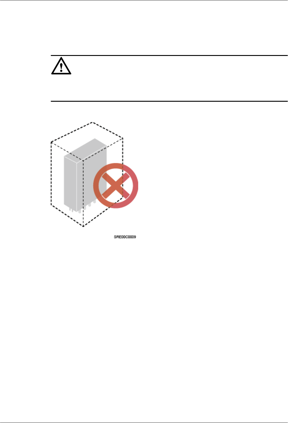
lThe pRRU cannot be installed in an enclosed equipment room without a cooling system.
lWhen multiple pRRUs are installed in centralized mode, the minimum clearance
requirements must be met. For details, see 9.1.3 Installation Clearance and Space
Requirements.
NOTICE
If the pRRU is inappropriately installed, heat dissipation of the pRRU deteriorates and the
pRRU may not work properly, as shown in Figure 9-1.
Figure 9-1 Inappropriately installed pRRU
Correct installation methods:
To ensure the heat dissipation of the pRRU and waterproofing of the ports at the bottom of the
RRU, the vertical deviation angle of a pRRU must be less than or equal to 10°, as shown in
Figure 9-2.
DBS3900 LampSite
Installation Guide 9 Installing a pRRU3907
Issue 07 (2015-12-30) Huawei Proprietary and Confidential
Copyright © Huawei Technologies Co., Ltd.
159
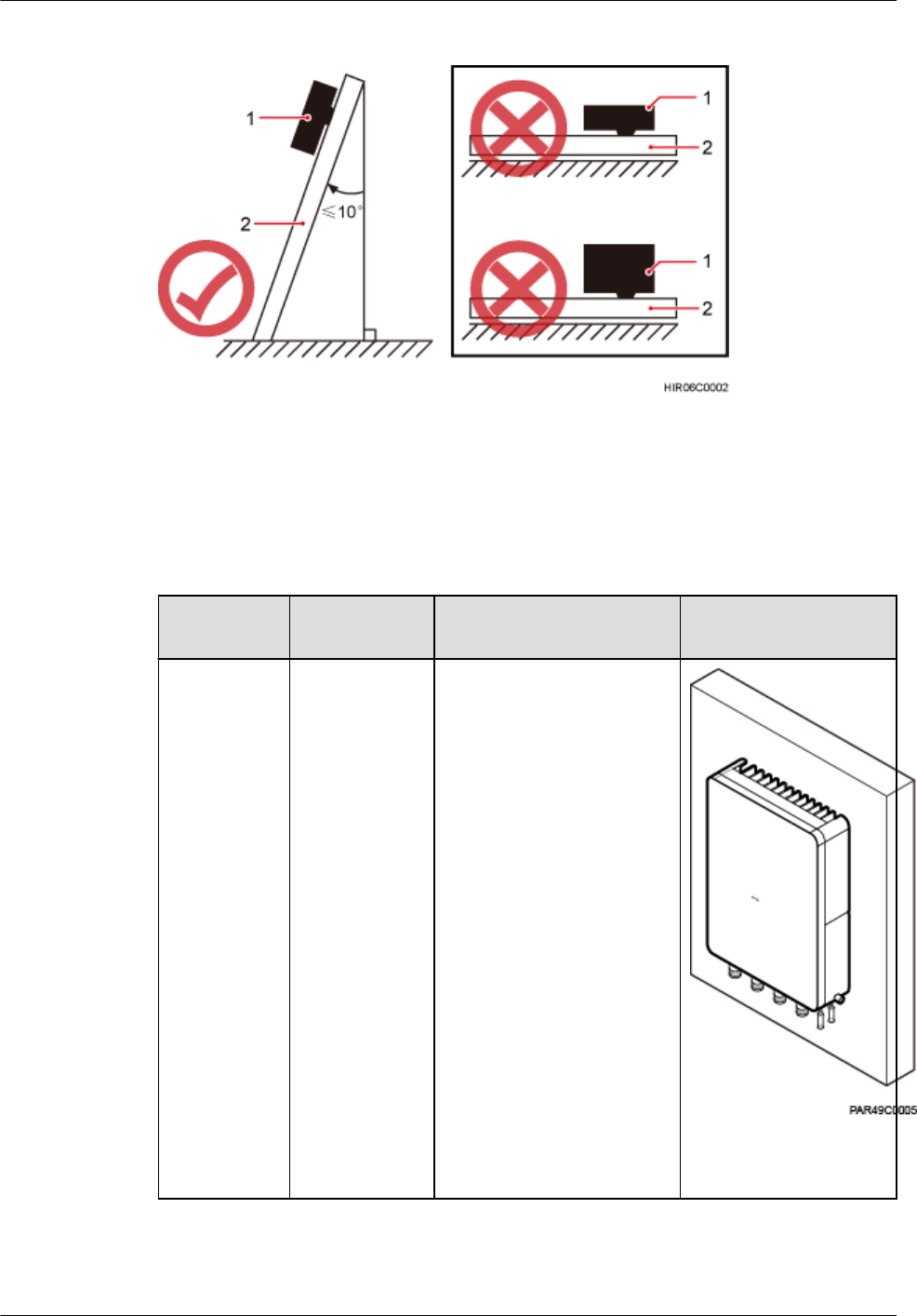
Figure 9-2 Requirements for the vertical deviation angle of a pRRU
(1) pRRU (2) Installation support (pole or wall)
Table 9-2 lists the mounted suggestions of different installation scenarios.
Table 9-2 mounted suggestion
Installation
Mode
Requirement
s
Mounting Brackets Installation Diagram
Installing the
pRRU3907
on a wall
For details,
see9.3.2
Installing a
pRRU3907
on a Wall.
lThe wall
can bear a
load at least
four times
the weight
of a
pRRU3907.
lThe screws
must be
tightened
with a
torque of 30
N·m. This
ensures the
screws
work
properly
and the wall
remains
intact
without
cracks in it.
1. M6x60 bolt
2. Nut
3. Spring washer
4. Flat washer
5. Expansion sleeve
DBS3900 LampSite
Installation Guide 9 Installing a pRRU3907
Issue 07 (2015-12-30) Huawei Proprietary and Confidential
Copyright © Huawei Technologies Co., Ltd.
160
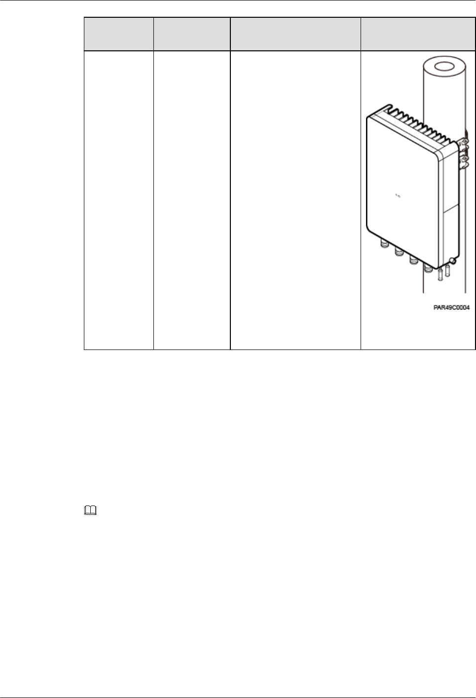
Installation
Mode
Requirement
s
Mounting Brackets Installation Diagram
Installing the
pRRU3907
on a pole
For details,
see 9.3.3
Installing a
pRRU3907
on a Pole.
lThe
diameter of
a pole for
installing a
pRRU
ranges from
60 mm
(2.36 in.) to
114 mm
(4.49 in.).
The
recommend
ed diameter
is 80 mm
(3.15 in.).
lThe
recommend
ed thickness
of the pole
wall is 3.5
mm (0.14
in.) or
above.
1. Mounting kit
2. Hose clamp
9.1.3 Installation Clearance and Space Requirements
This section describes the recommended and minimum clearances for a pRRU.
Clearance for a pRRU
When the pRRU3907 is installed on a wall or pole, the minimum clearance is required for
easy cabling and operation and maintenance (O&M). Based on the engineering practice, the
recommendation for the installation clearance is provided.
NOTE
lThe recommended clearances are for customers, ensuring normal running and providing appropriate
space for O&M. If installation space is sufficient, leave the recommended clearances after installing
equipment.
lThe minimum clearance ensures normal operation and heat dissipation, but O&M activities such as
checking indicator status and opening the cover plate of a cabling cavity cannot be properly conducted. If
installation space is restricted, leave the minimum clearance after installing equipment.
Figure 9-3 show the clearances for installing a pRRU3907.
DBS3900 LampSite
Installation Guide 9 Installing a pRRU3907
Issue 07 (2015-12-30) Huawei Proprietary and Confidential
Copyright © Huawei Technologies Co., Ltd.
161
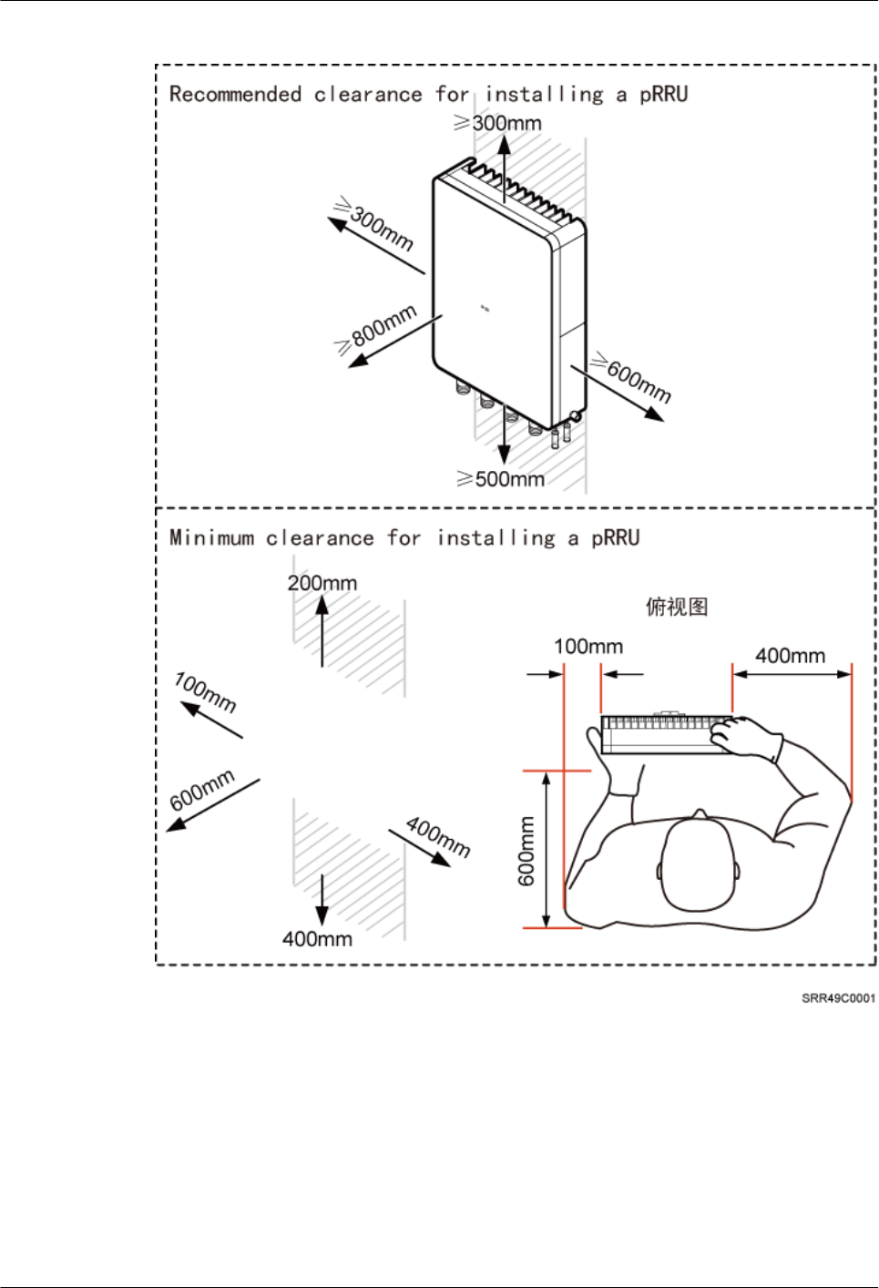
Figure 9-3 Clearances for installing a pRRU3907
Installation Spacing Between pRRUs
Table 9-3 lists the horizontal and vertical spacing between pRRUs.
DBS3900 LampSite
Installation Guide 9 Installing a pRRU3907
Issue 07 (2015-12-30) Huawei Proprietary and Confidential
Copyright © Huawei Technologies Co., Ltd.
162
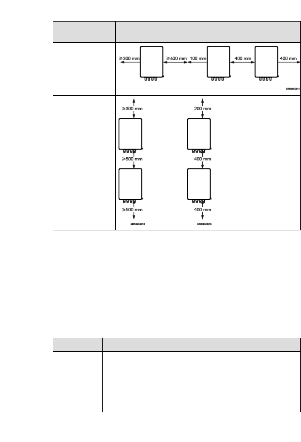
Table 9-3 spacing between pRRUs
Item Recommended
Spacing
Minimum Spacing
Horizontal
Vertical
9.1.4 Installation Environment Requirements
The installation environment of a pRRU3907 involves the running environment specifications
for the pRRU3907.
Running Environment Specifications
Table 9-4 shows the environment specifications for the pRRU3907 installed outdoors.
Table 9-4 pRRU3907 environment specifications
Specifications Condition Remarks
Operating
temperature
- 40 °C to + 50 °C At a temperature of -40°C to
-20°C, the pRRU3907 can only
start without fulfilling performance
requirements. Working at a
temperature of -20°C to +50°C, the
pRRU3907 can fulfill all
performance requirements.
DBS3900 LampSite
Installation Guide 9 Installing a pRRU3907
Issue 07 (2015-12-30) Huawei Proprietary and Confidential
Copyright © Huawei Technologies Co., Ltd.
163
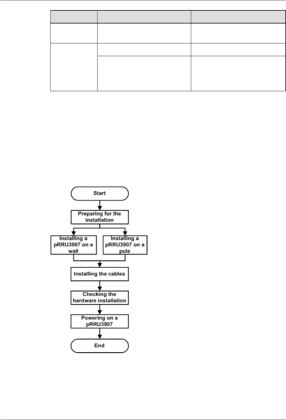
Specifications Condition Remarks
Relative
humidity
5% RH to 95% RH -
Altitude - 60 m to + 1800 m Works properly.
1800 m to 4000 m Above the 1800 m altitude, the
maximum operating temperature
decreases by 1 °C each time the
altitude increases by 220 m.
9.2 Installation Process
This section describes the pRRU3907 installation process, which involves installing a
pRRU3907, and cables, checking the pRRU3907 hardware installation, and powering on the
pRRU3907.
Figure 9-4 shows the pRRU3907 installation process.
Figure 9-4 pRRU3907 installation process
9.3 Installing a pRRU3907
This section describes the pRRU3907 installation process.
DBS3900 LampSite
Installation Guide 9 Installing a pRRU3907
Issue 07 (2015-12-30) Huawei Proprietary and Confidential
Copyright © Huawei Technologies Co., Ltd.
164
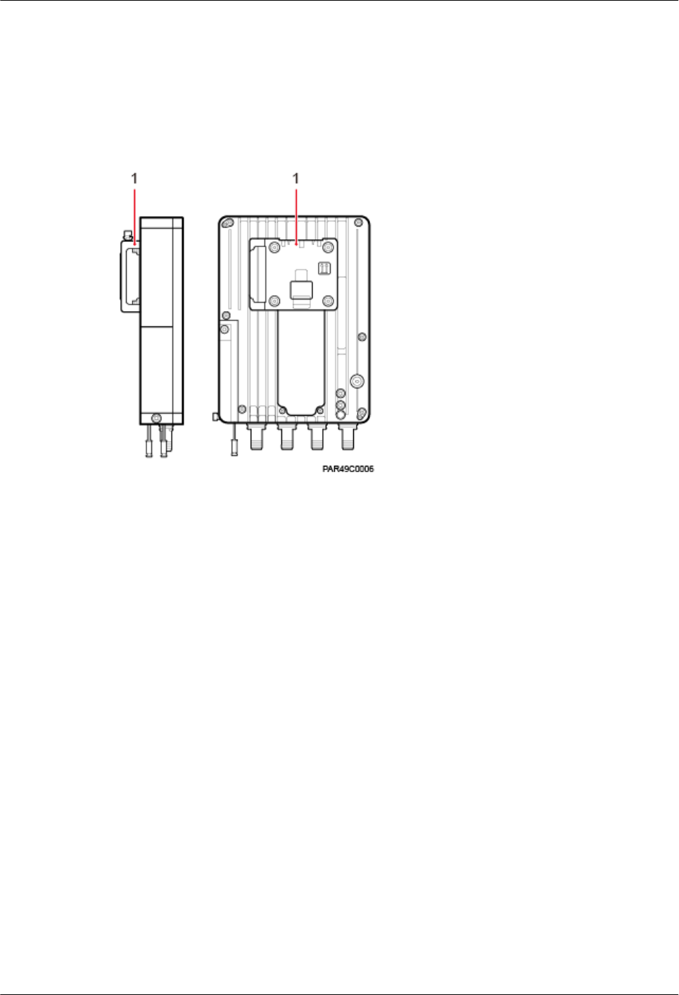
9.3.1 pRRU3907 Mounting Kits
This section describes mounting kits and attachment plates for installing pRRU3907s.
Figure 9-5 shows the exterior of the pRRU3907.
Figure 9-5 Front and side of a pRRU3907
(1) Attachment plate
Figure 9-6 shows a mounting bracket and a attachment plate.
DBS3900 LampSite
Installation Guide 9 Installing a pRRU3907
Issue 07 (2015-12-30) Huawei Proprietary and Confidential
Copyright © Huawei Technologies Co., Ltd.
165
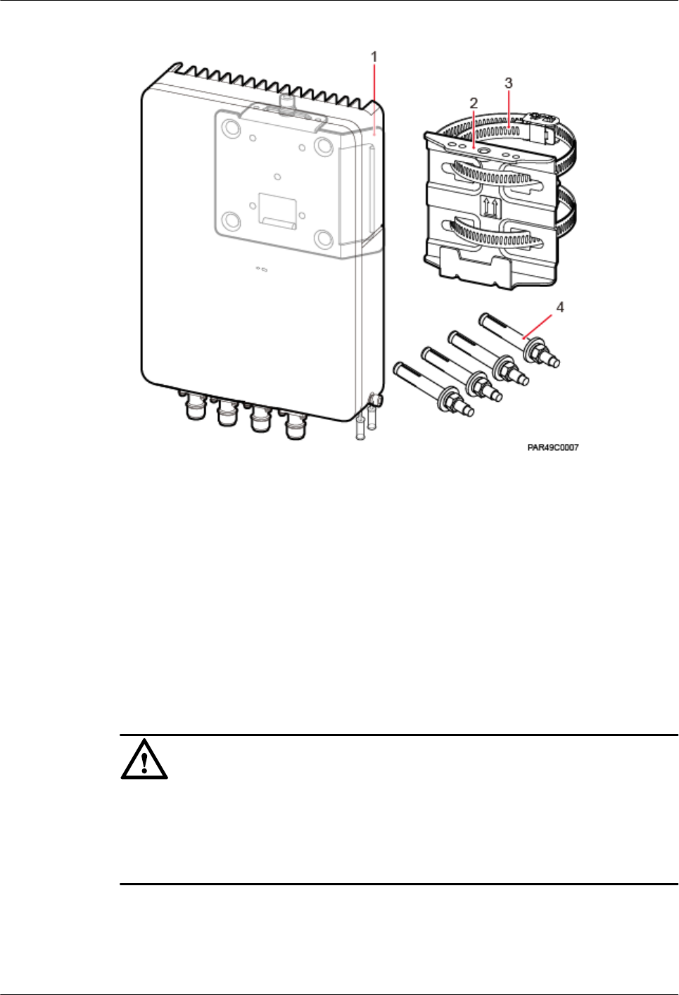
Figure 9-6 Mounting bracket and common attachment plate for installing a pRRU3907
(1) Attachment plate (2) Mounting bracket (3) Hose clamp (4) Expansion bolt
9.3.2 Installing a pRRU3907 on a Wall
This section describes the procedure and precautions for installing a pRRU3907 on a wall.
Context
The wall for installing pRRU3907s must meet the following requirements:
lThe wall must be able to bear a weight four times heavier than the pRRU3907's weight.
lExpansion bolts must be tightened to 30 N·m (265.52 lbf·in.) to ensure that the bolt
assemblies work properly and the wall remains intact.
NOTICE
lDo not stand a pRRU3907 upright because the RF ports cannot support the weight of the
pRRU3907.
lPlace a foam pad or cardboard under a pRRU3907 to protect the pRRU3907 housing from
damage during the installation.
DBS3900 LampSite
Installation Guide 9 Installing a pRRU3907
Issue 07 (2015-12-30) Huawei Proprietary and Confidential
Copyright © Huawei Technologies Co., Ltd.
166
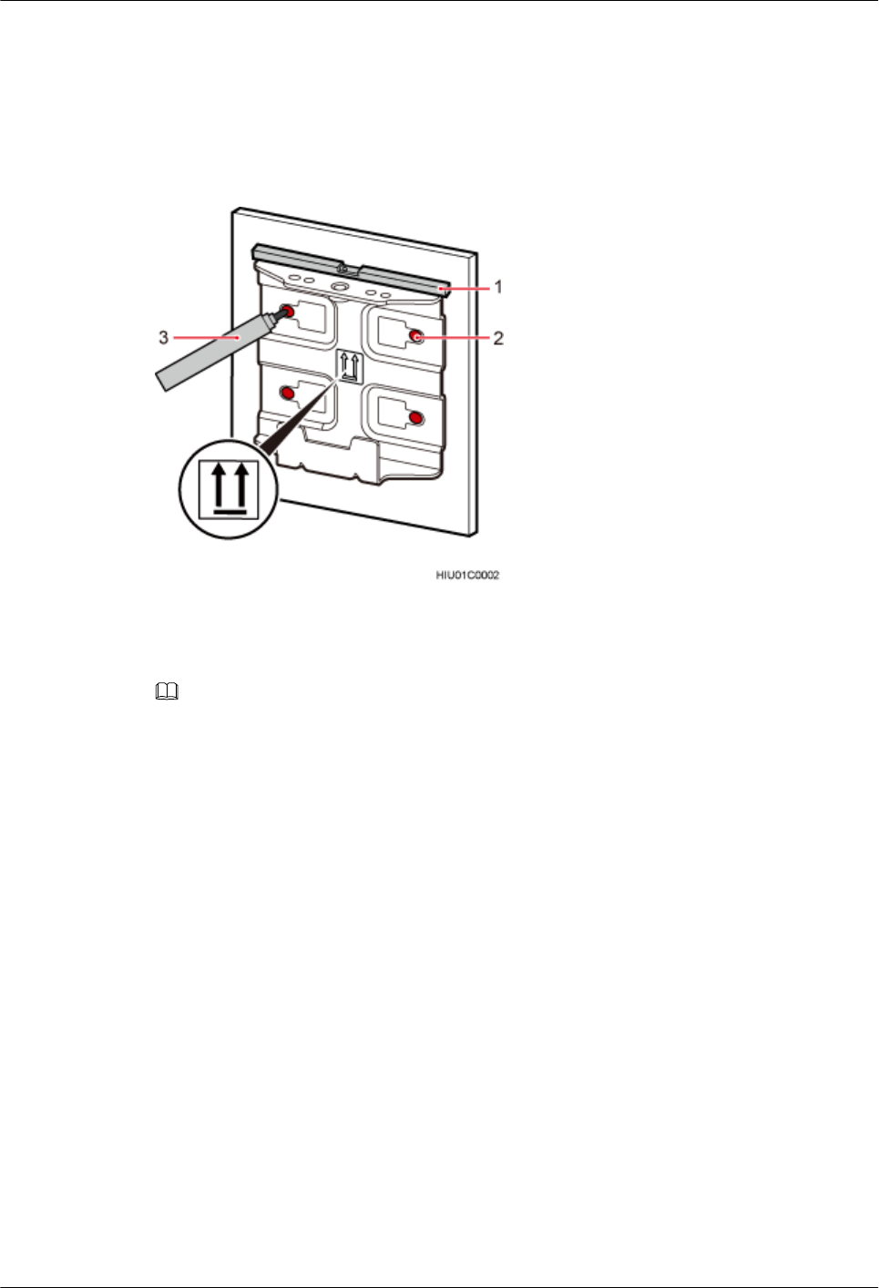
Procedure
Step 1 Determine a position for installing the pRRU3907 on a wall, use a level to verify that the
marking-off template is placed horizontally, and then use a marker to mark anchor points, as
shown in Figure 9-7.
Figure 9-7 Marking anchor points
(1) Level (2) Tapped hole (3) Marker
NOTE
It is recommended that the separate mounting kit be 1200 mm (47.24 in.) to 1600 mm (62.99 in.) above
the ground.
Step 2 Drill holes at the anchor points and install expansion bolts in the holes, as shown in Figure
9-8.
DBS3900 LampSite
Installation Guide 9 Installing a pRRU3907
Issue 07 (2015-12-30) Huawei Proprietary and Confidential
Copyright © Huawei Technologies Co., Ltd.
167
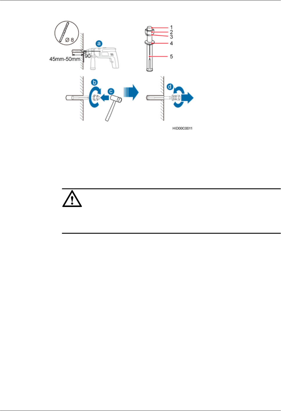
Figure 9-8 Drilling a hole and inserting an expansion bolt assembly
(1) M6x60 bolt (2) Nut (3) Spring washer (4) Flat washer (5) Expansion tube
1. Use a hammer drill with a φ8 bit to drill holes vertically at the marked anchor points.
Ensure that the depth of each hole ranges from 45 mm (1.77 in.) to 50 mm (1.97 in.).
NOTICE
Take proper safety measures to protect your eyes and respiratory tract against the dust
before drilling holes.
2. Use a vacuum cleaner to clear the dust out from inside and around the holes, and
measure the distances between holes. If any of the holes is beyond the acceptable range,
mark a new anchor point and drill a new hole.
3. Tighten the expansion bolts slightly, and place each expansion bolt vertically into each
hole.
4. Use a rubber mallet to pound each expansion bolt until the corresponding expansion tube
completely enters the hole. Leave 20 mm (0.79 in.) of the expansion bolt outside the
wall.
5. Remove the M6x60 bolt, nut, spring washer, and flat washer in sequence.
Step 3 Place the mounting kit onto the wall, insert four M6x60 bolts into the tapped holes on the
mounting kit, and tighten each bolt to 5 N·m (44.25 lbf·in.) to secure the mounting kit, as
shown in Figure 9-9.
DBS3900 LampSite
Installation Guide 9 Installing a pRRU3907
Issue 07 (2015-12-30) Huawei Proprietary and Confidential
Copyright © Huawei Technologies Co., Ltd.
168
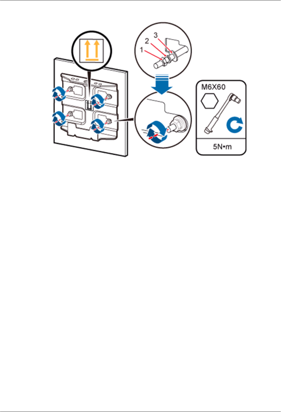
Figure 9-9 Securing the separate mounting kit
(1) Nut (2) Spring washer (3) Flat washer
Step 4 Hold the pRRU3907, hang the two dowels on the top of the pRRU3907 attachment plate onto
the separate mounting kit, and push the pRRU3907 until it snaps into place, as shown by
illustrations a and b in Figure 9-10.
Step 5 Use the M6 inner hexagon screwdriver to tighten the screw on the top of the separate
attachment plate to 7 N·m (61.96 lbf·in.), as shown by illustration c in Figure 9-10.
DBS3900 LampSite
Installation Guide 9 Installing a pRRU3907
Issue 07 (2015-12-30) Huawei Proprietary and Confidential
Copyright © Huawei Technologies Co., Ltd.
169
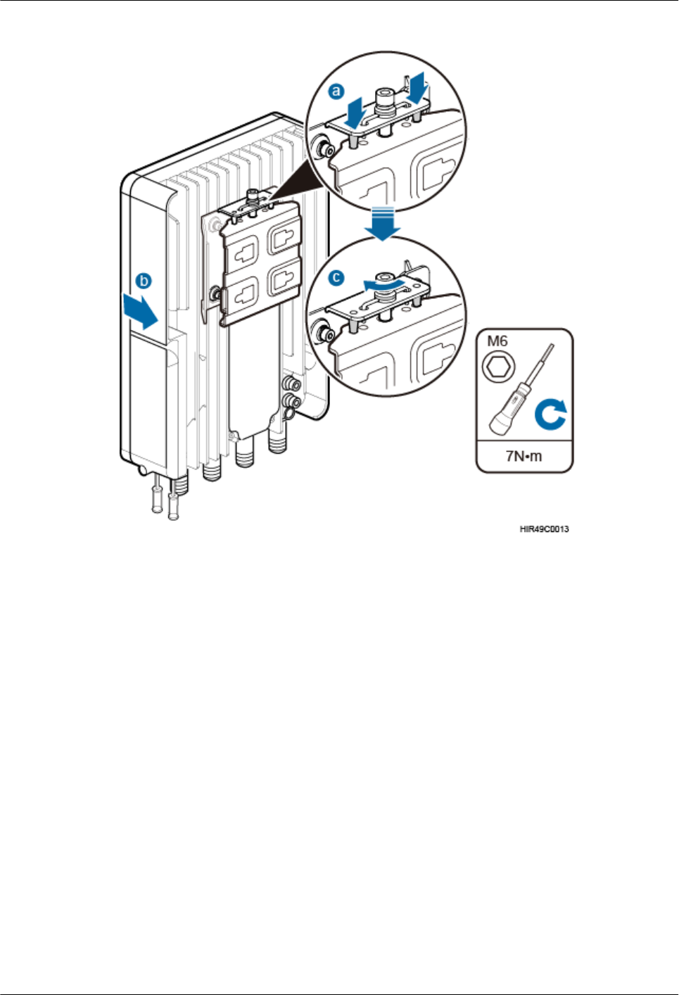
Figure 9-10 Securing the pRRU3907 onto the mounting kit
----End
9.3.3 Installing a pRRU3907 on a Pole
This section describes the procedure and precautions for installing a pRRU3907 on a pole.
Context
lDo not stand a pRRU3907 upright because the RF ports cannot support the weight of the
pRRU3907.
lPlace a foam pad or cardboard under a pRRU3907 to protect the pRRU3907 housing
from damage during the installation.
Procedure
Step 1 Determine a position for installing the separate mounting kit, as shown in Figure 9-11.
DBS3900 LampSite
Installation Guide 9 Installing a pRRU3907
Issue 07 (2015-12-30) Huawei Proprietary and Confidential
Copyright © Huawei Technologies Co., Ltd.
170
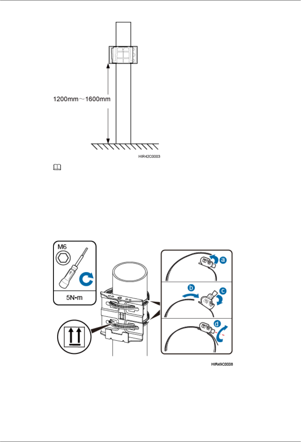
Figure 9-11 Distance between the separate mounting kit and the ground
NOTE
It is recommended that the separate mounting kit be 1200 mm (47.24 in.) to 1600 mm (62.99 in.) above the
ground.
Step 2 Install the mounting kit, as shown in Figure 9-12.
Figure 9-12 Installing a pRRU3907 mounting kit
1. Determine a position for installing the pRRU3907. Then, place the separate mounting kit
onto the pole, thread the hose clamp through the mounting kit, and encircle the pole with
the hose clamp, as shown by illustrations a, b, and c in Figure 9-12.
2. Use an M6 inner hexagon screwdriver to tighten the bolt on each hose clamp to 5 N·m
(44.25 lbf·in.) to secure the mounting kit, as shown by illustration d in Figure 9-12.
DBS3900 LampSite
Installation Guide 9 Installing a pRRU3907
Issue 07 (2015-12-30) Huawei Proprietary and Confidential
Copyright © Huawei Technologies Co., Ltd.
171
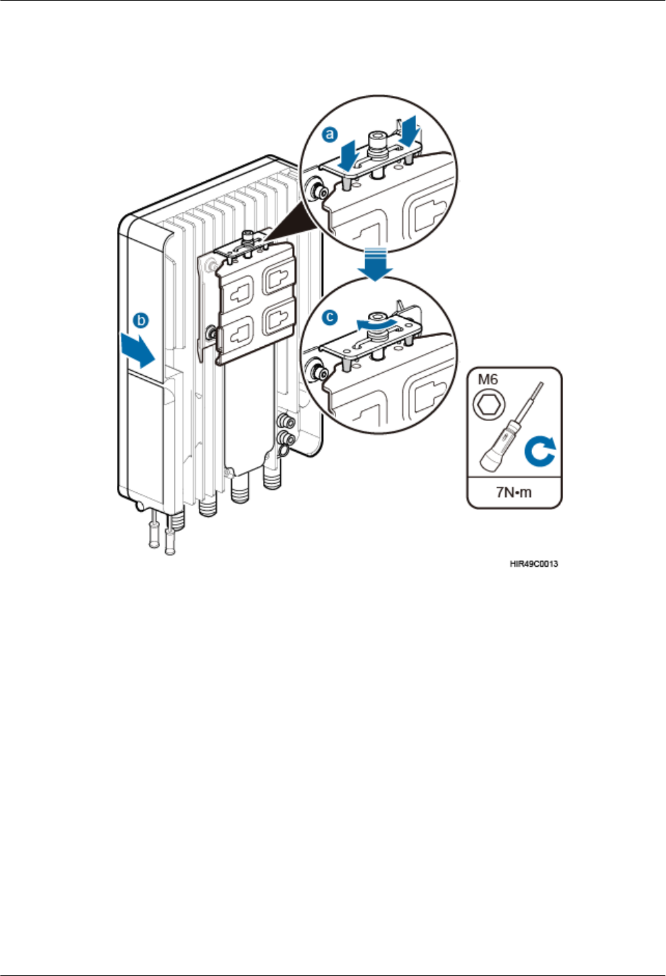
Step 3 Secure the pRRU3907 onto the separate mounting kit, as shown in Figure 9-13.
Figure 9-13 Securing the pRRU3907 onto the mounting kit
1. Hang the two dowels on the top of the pRRU3907 attachment plate onto the mounting
kit, and push the pRRU3907 until it snaps into place, as shown by illustrations a and b in
Figure 9-13.
2. Use the M6 inner hexagon screwdriver to tighten the screw on the top of the attachment
plate to 7 N·m (61.96 lbf·in.), as shown by illustration c in Figure 9-13.
----End
9.4 Installing pRRU3907 Cables
This chapter describes the procedures for installing pRRU3907 cables.
9.4.1 Cabling Requirements
Cables must be laid out according to the specified cabling requirements to prevent signal
interference.
DBS3900 LampSite
Installation Guide 9 Installing a pRRU3907
Issue 07 (2015-12-30) Huawei Proprietary and Confidential
Copyright © Huawei Technologies Co., Ltd.
172

NOTE
If a cable listed below is not required, skip the cabling requirements of the cable.
General Cabling Requirements
Bending radius requirements
lThe bending radius of a 7/8'' feeder must be greater than 250 mm (9.84 in.), and the
bending radius of a 5/4'' feeder must be greater than 380 mm (14.96 in.).
lThe bending radius of a 1/4'' jumper must be greater than 35 mm (1.38 in.). The bending
radius of a super-flexible 1/2'' jumper must be greater than 50 mm (1.97 in.), and the
bending radius of an ordinary 1/2'' jumper must be greater than 127 mm (5.00 in.).
lThe bending radius of a PGND cable must be at least three times its diameter.
lThe bending radius of a signal cable must be at least five times its diameter.
Cable binding requirements
lCables of the same type must be bound together.
lDifferent types of cables must be separately laid out and bound, with a minimum
distance of 30 mm (1.18 in.) from each other.
lCables must be bound tightly and neatly. The sheaths of cables must not be damaged.
lCable ties must face the same direction, and those at the same horizontal line must be in
a straight line.
lThe excess of indoor cable ties must be cut off. The excess of 5 mm (0.197 in.) of
outdoor cable ties should be reserved, and the cut surfaces must be smooth without sharp
edges.
lAfter cables are installed, labels or nameplates must be attached to the cables at their
ends, curves, and interconnection positions.
Security requirements
lWhen laying out cables, avoid sharp objects, for example sharp edges on the wall. If
necessary, use tubes to protect the cables.
lWhen laying out cables, keep cables away from heat sources, or use heat insulation
materials to insulate the cables from the heat sources.
lReserve a proper distance (0.1 m [3.937 in.] is recommended) between equipment and
cables especially at the cable curves to protect the cables and equipment.
Indoor cabling requirements
lRoute each cable into the room through the feeder window.
lReserve drip loops for all cables outside the feeder window before routing them into the
room. Ensure that the radiuses of the drip loops are greater than or equal to the minimum
bending radiuses of the cables.
lWhen routing a cable into the room, ensure that a person is assisting you in the room.
lApply waterproof treatment to the feeder window.
Outdoor Cabling Requirements
lProtect outdoor cables against potential damage. For example, thread the cables through
tubes.
lCables to be protected include AC power cables, transmission cables, and cables laid out
underground.
DBS3900 LampSite
Installation Guide 9 Installing a pRRU3907
Issue 07 (2015-12-30) Huawei Proprietary and Confidential
Copyright © Huawei Technologies Co., Ltd.
173

lUse cable clips to secure cables outdoors.
lArrange cables neatly along the routing direction and use cable clips to secure the cables.
lDetermine the positions where the clips are installed according to the actual situation.
For example, 7/8" feeders are secured with clips at an interval of 1.5 m (4.92 ft) to 2 m
(6.56 ft), and CPRI fiber optic cables and power cables are secured with clips at an
interval of 1 m (3.28 ft) to 1.5 m (4.92 ft). Ensure that the clips are evenly spaced and in
the same direction.
lWhen fastening cables with a clip, ensure that the cables are aligned neatly and are
routed through the holes in the clip. Do not stretch the cables too tightly.
lWhen using clips to secure cables, tighten the screws on the clips after all cables are
arranged and laid out.
Special Cabling Requirements
Cabling of PGND cables
lPGND cables for a base station must be connected to the same ground bar.
lPGND cables must be buried in the ground or routed indoors.
lThe external conductor of the coaxial wire and the shield layer of the shielded cable must
have proper electrical contact with the metal surface of the equipment which they are
connected to.
lPGND cables and signal cables must be installed separately. A certain distance must be
reserved between them to prevent interference from each other.
lSwitches or fuses must not be installed on the PGND cables.
lOther devices must not be used for electrical connections of the PGND cables.
lAll the metal parts in the housing of the equipment must be reliably connected to the
ground terminal.
9.4.2 pRRU3907 Cable List
This section describes pRRU3907 cables, connectors added to the pRRU3907 cables, and
installation positions for both ends of each cable.
Table 9-5 lists pRRU3907 cables.
Table 9-5 List of pRRU3907 cables
Cable One End The Other End
Connector Connected
to ...
Connector Connected to ...
Ethernet
Cable
RJ45 connector RHUB/
CPRI_E0~CP
RI_E7 port
RJ45 connector pRRU3907/
CPRI_E0~CPRI_
E1 port
pRRU3907
RF Jumper
Type N male
connector
RF port on the
pRRU3907
Depends on the
port model of
the antenna
system
Antenna system
DBS3900 LampSite
Installation Guide 9 Installing a pRRU3907
Issue 07 (2015-12-30) Huawei Proprietary and Confidential
Copyright © Huawei Technologies Co., Ltd.
174
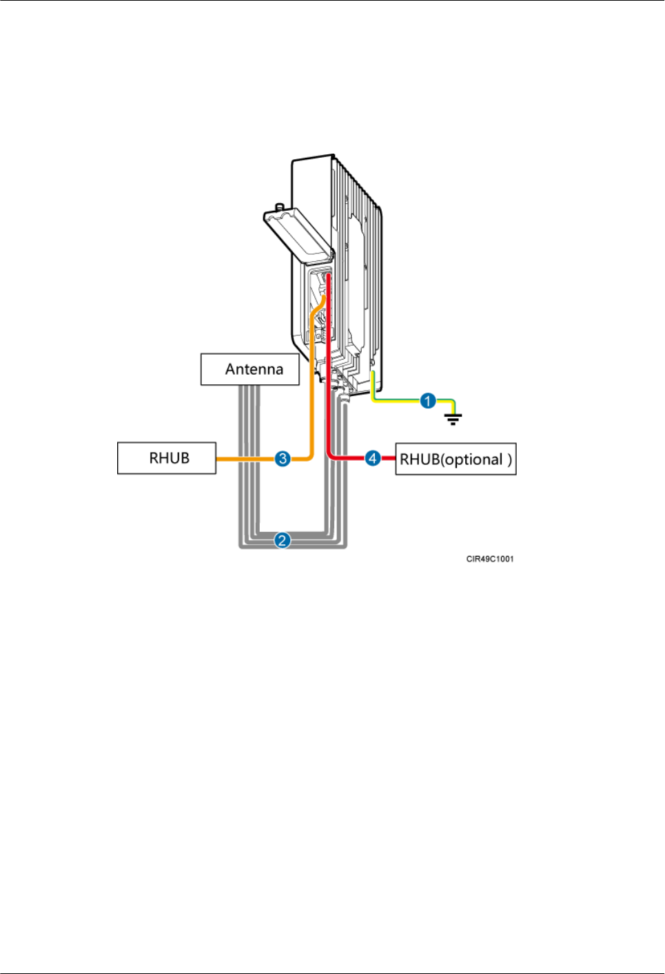
9.4.3 pRRU3907 Cable Connections
This section describes pRRU3907 cable connections.
Figure 9-14 shows the cable connections when a pRRU3907 is installed.
Figure 9-14 Cable connections when a pRRU3907 is installed
(1) pRRU3907 PGND
cable
(2) pRRU3907 RF jumper (3) pRRU3907 Ethernet
cable
(4) pRRU3907 Ethernet
cable
9.4.4 pRRU3907 cable installation process
This section describes the process of installing pRRU3907 cables.
Figure 9-15 shows the process of installing pRRU3907 cables.
DBS3900 LampSite
Installation Guide 9 Installing a pRRU3907
Issue 07 (2015-12-30) Huawei Proprietary and Confidential
Copyright © Huawei Technologies Co., Ltd.
175
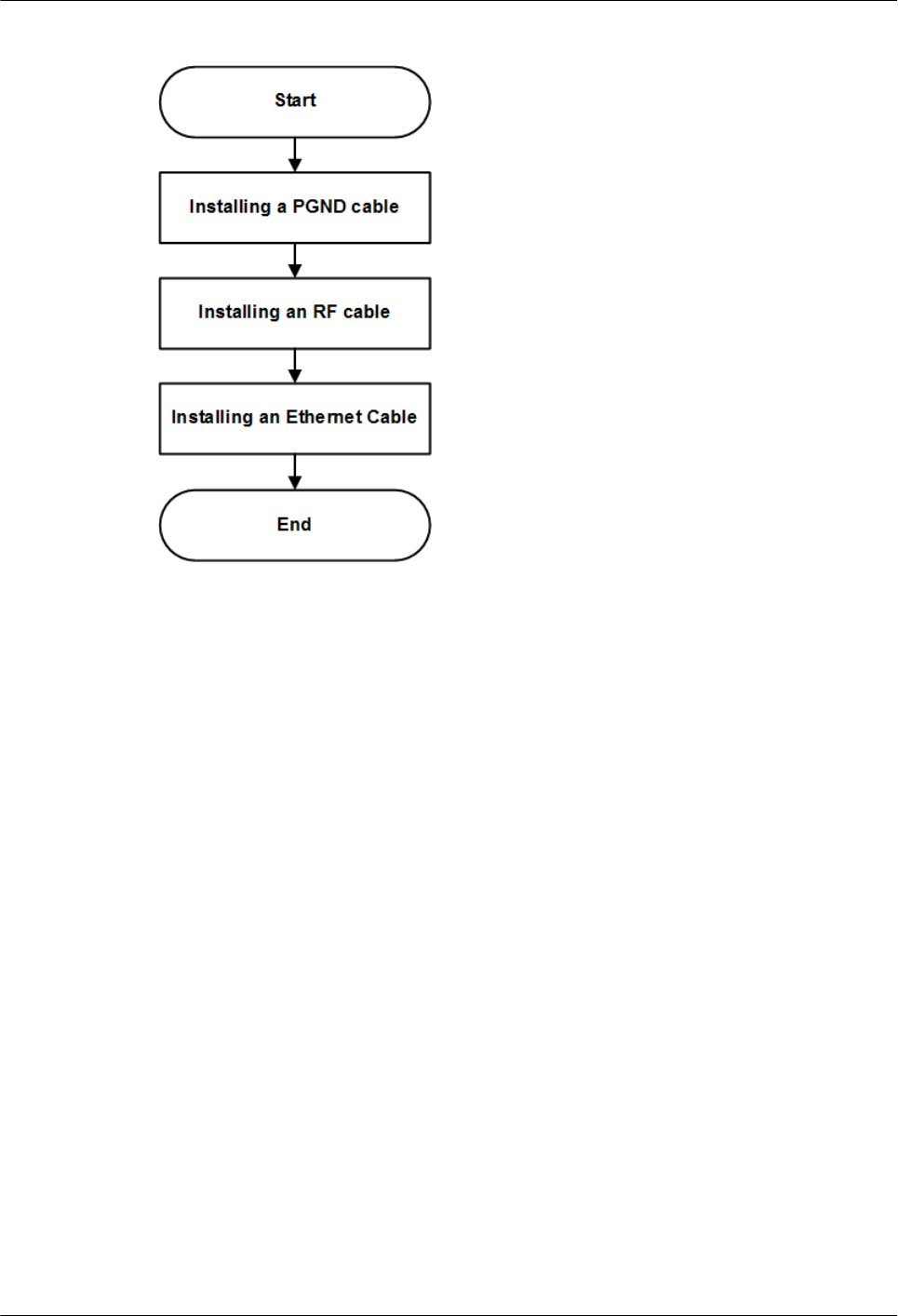
Figure 9-15 pRRU3907 cable installation process
9.4.5 Installing a PGND Cable
This section describes the procedure for installing a PGND cable.
Procedure
Step 1 Prepare a pRRU3907 PGND cable.
1. Cut the cable to a length suitable for the actual cable route.
2. Add OT terminals to both ends of the cable by following the instructions in Assembling
the OT Terminal and the Power Cable.
Step 2 Install the pRRU3907 PGND cable.
Connect one end of the PGND cable with an M6 OT terminal to the ground terminal at the
RRU bottom and the other end of the cable with an M8 OT terminal to the external ground
bar, as shown in Figure 9-16.
DBS3900 LampSite
Installation Guide 9 Installing a pRRU3907
Issue 07 (2015-12-30) Huawei Proprietary and Confidential
Copyright © Huawei Technologies Co., Ltd.
176
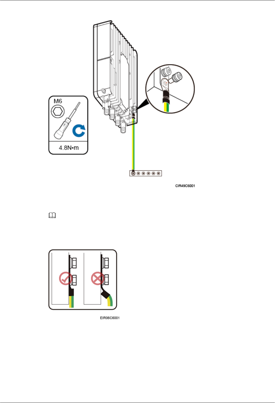
Figure 9-16 Installing a pRRU3907 PGND cable
NOTE
Crimp OT terminals in correct directions, as shown in Figure 9-17.
Figure 9-17 Correct direction for crimping an OT terminal
Step 3 Label the installed cable by following the instructions in 14.5 Attaching a Sign Plate Label.
----End
9.4.6 Installing an RF Jumper
This section describes the procedure for installing an RF jumper.
DBS3900 LampSite
Installation Guide 9 Installing a pRRU3907
Issue 07 (2015-12-30) Huawei Proprietary and Confidential
Copyright © Huawei Technologies Co., Ltd.
177
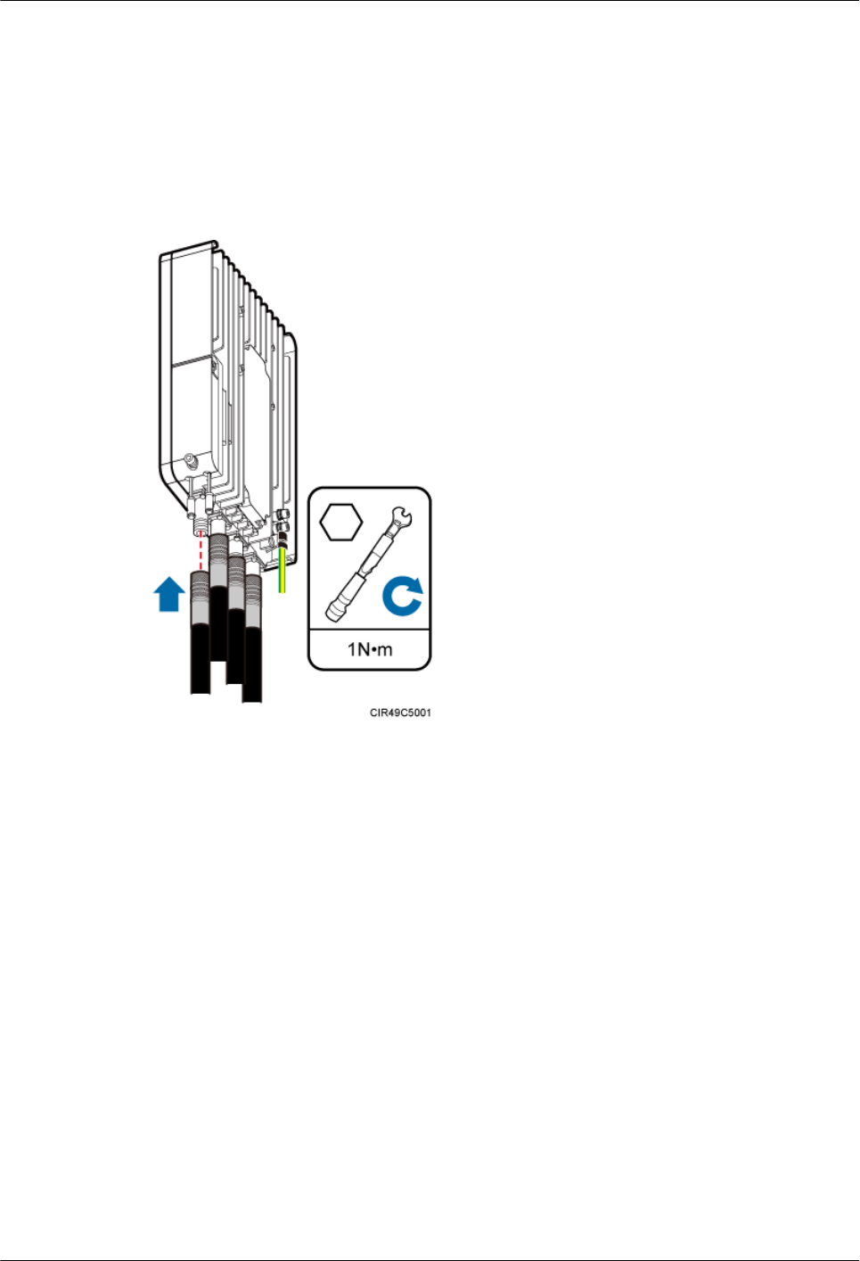
Procedure
Step 1 Remove the dustproof cap from the ANT port to be used on the pRRU3907.
Step 2 Connect the type N male connector at one end of the pRRU3907 RF jumper to the ANT port
at the bottom of the pRRU3907 in sequence, and use a torque wrench to tighten the connector
to 1 N·m (8.85 lbf·in.), as shown in Figure 9-18.
Figure 9-18 Installing an RF jumper
Step 3 Connect the other end of the pRRU3907 RF jumper to the external antenna system.
Step 4 Waterproof the connector of the RF jumper by cold shrink sleeve, as shown in Figure 9-19.
DBS3900 LampSite
Installation Guide 9 Installing a pRRU3907
Issue 07 (2015-12-30) Huawei Proprietary and Confidential
Copyright © Huawei Technologies Co., Ltd.
178
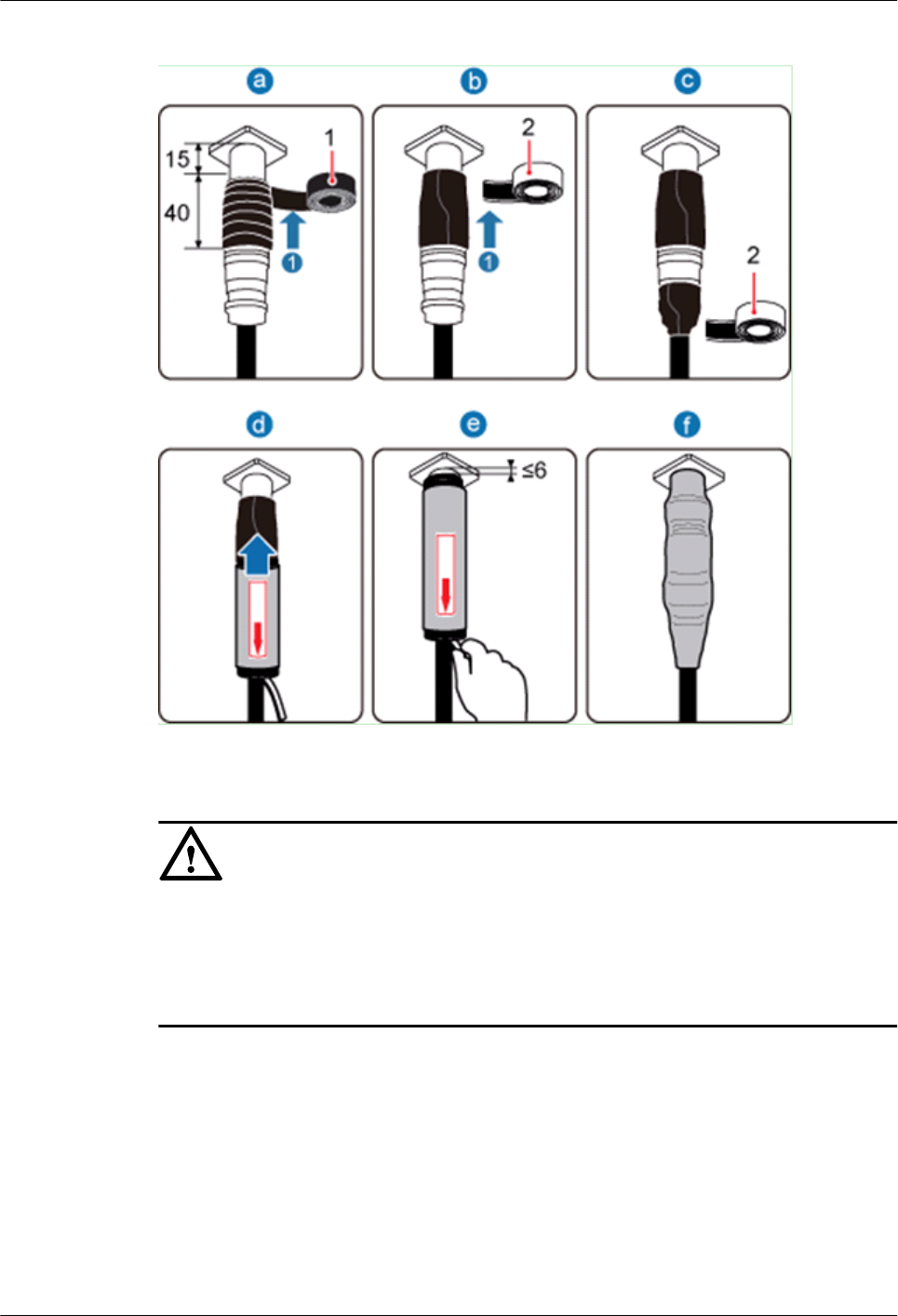
Figure 9-19 Waterproofing the connector of the RF jumper
NOTICE
lWrap cold shrink sleeves around the RF jumpers before installing the connectors.
lDo not rotate the adjacent connectors of a connector that has been wrapped with a cold
shrink sleeve. Otherwise, the cold shrink sleeve may be damaged.
lDuring installation, ensure that no foreign substance, including sand, enters the sleeve.
1. Wrap a PVC insulation tape around the exposed area of the connector. The wrapped area
is 15 mm away from the end of the connector, with a total length of 40 mm.
2. Ensure that dimensions (L x W) of the waterproof tape is 50 mm x 50 mm. Stretch the
tape horizontally until it is twice of the original length and wrap it around the upper area
of the connector.
Ensure that the upper end of the waterproof tape overlays that of the PVC insulation
tape.
3. Push the cold shrink sleeve to the end of the pRRU3907 connector while gently pulling
out the support strip along the jumper until the sleeve shrinks and secures the connector.
DBS3900 LampSite
Installation Guide 9 Installing a pRRU3907
Issue 07 (2015-12-30) Huawei Proprietary and Confidential
Copyright © Huawei Technologies Co., Ltd.
179
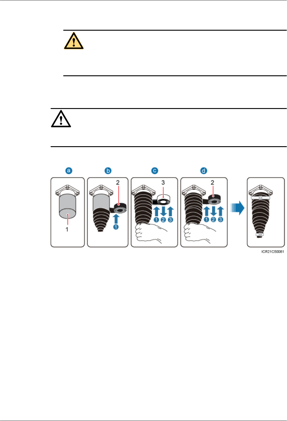
4. Pull out the support strip along the direction indicated by the arrow.
CAUTION
Ensure that the sleeve shrinks around the end of the pRRU3907 connector and that the
upper end of the sleeve and the connector end is 6 mm apart or less.
Step 5 Check the dustproof caps on antenna connectors. In outdoor scenarios, dustproof caps must be
waterproofed, as shown in Figure 9-20.
NOTICE
Do not remove dustproof caps from vacant antenna connectors.
Figure 9-20 Waterproofing a dustproof cap
(1) Dustproof cap (2) PVC insulation tape (3) Waterproof tape
1. Verify that dustproof caps are not removed.
2. Wrap one layer of PVC insulation tape on each connector from bottom up.
3. Wrap three layers of waterproof tape on each connector, first from bottom up, then from
top down, and finally from bottom up. Wrap each layer of the tape around the connector
tightly.
4. Wrap three layers of PVC insulation tape on each connector, first from bottom up, then
from top down, and finally from bottom up. Wrap each layer of the tape around the
connector tightly.
DBS3900 LampSite
Installation Guide 9 Installing a pRRU3907
Issue 07 (2015-12-30) Huawei Proprietary and Confidential
Copyright © Huawei Technologies Co., Ltd.
180
NOTE
lWhen wrapping waterproof tape, stretch the tape evenly until it is twice of the original length. When
wrapping PVC insulation tape, do not stretch it.
lWrap each layer of tape around each connector tightly and neatly, and ensure that the adhesive surface of
each layer of tape overlaps more than 50% of the lower layer.
lWhen cutting off a cable tie, reserve a surplus length of 3 mm (0.12 in.) to 5 mm (0.20 in.).
----End
Follow-up Procedure
1. Route the cable by following the instructions in section 9.4.1 Cabling Requirements
and use cable ties to bind the cable.
2. Label the installed cable. For details, see section 14.5 Attaching a Sign Plate Label and
Attaching the Color Ring.
9.4.7 Opening the Cover Plate of a pRRU3907 Cabling Cavity
This section describes the procedure for opening the cover plate of a pRRU3907 cabling
cavity.
Procedure
Step 1 Wear ESD gloves.
NOTICE
Take proper ESD protection measures, for example, wear ESD gloves, to prevent electrostatic
damage to boards, modules, or electronic components.
Step 2 Use an M6 inner hexagon screwdriver to loosen the screw on the cover plate of the
pRRU3907 cabling cavity, and open the cover plate, as shown in Figure 9-21.
DBS3900 LampSite
Installation Guide 9 Installing a pRRU3907
Issue 07 (2015-12-30) Huawei Proprietary and Confidential
Copyright © Huawei Technologies Co., Ltd.
181

Figure 9-21 Opening the cover plate of the pRRU3907 cabling cavity
(1) Cover plate (2) Cabling cavity (3) Cable clip for Ethernet cables
(4) Cable clip for Ethernet cables (5) Cable trough for Ethernet cables (6) Cable trough for Ethernet cables
(7) Waterproof block - -
Step 3 Remove the waterproof block.
NOTE
Remove only the waterproof blocks for cables to be installed.
----End
9.4.8 Installing an Ethernet Cable
This section describes how to install an Ethernet cable.
Context
lThe Ethernet cable must be of Category 5e (enhanced) or higher.
lWith the internal PoE module providing power, the maximum length of an Ethernet
cable is 100 m. With the Extender, the distance of the pRRU3907 and RHUB can be
extended by the Extender up to a total distance of 200 m.
lEthernet cables are not delivered, and they must be prepared onsite. You need to use a
network cable tester to test the Ethernet cable connection.
DBS3900 LampSite
Installation Guide 9 Installing a pRRU3907
Issue 07 (2015-12-30) Huawei Proprietary and Confidential
Copyright © Huawei Technologies Co., Ltd.
182
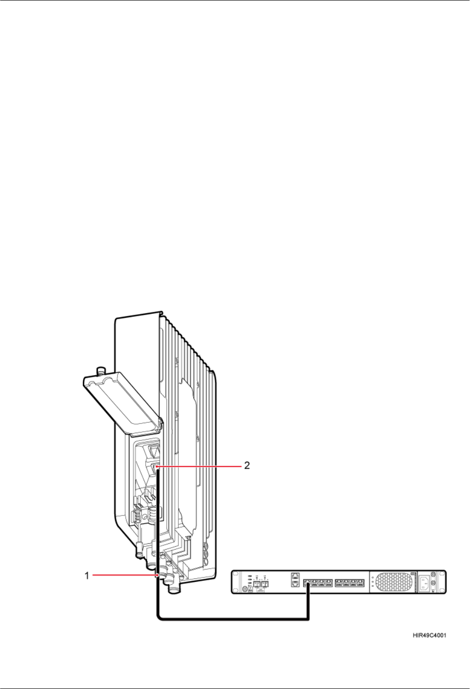
lThe Ethernet cable has the following functions:
–Provides power supply for the pRRU3907 when the cable connects the CPRI_E0
port on the pRRU3907 to the RHUB.
–Transmits CPRI signals between an RHUB and a pRRU3907.
Procedure
Step 1 Connect the RJ45 connector at one end of the Ethernet cable to the PoE port on the
pRRU3907 panel, and push the cables into the cable clips.
Step 2 Optional: Connect the RJ45 connector at the other end of the Ethernet cable to the output
port of the Extender. Then, connect the RJ45 connector at one end of another Ethernet cable
to the input port of the Extender.
In this scenario, the Ethernet cable is divided into two parts, one between the RHUB and the
Extender and the other between the Extender and the pRRU3907.
Step 3 Connect the RJ45 connector at the other end of the Ethernet cable to any port ranging from
CPRI_E0 to CPRI_E7 on the RHUB panel based on the engineering design, as shown in
Figure 9-22.
Figure 9-22 Installing an Ethernet cable
(1) Ethernet cable (2) CPRI_E0 port on the pRRU3907
DBS3900 LampSite
Installation Guide 9 Installing a pRRU3907
Issue 07 (2015-12-30) Huawei Proprietary and Confidential
Copyright © Huawei Technologies Co., Ltd.
183
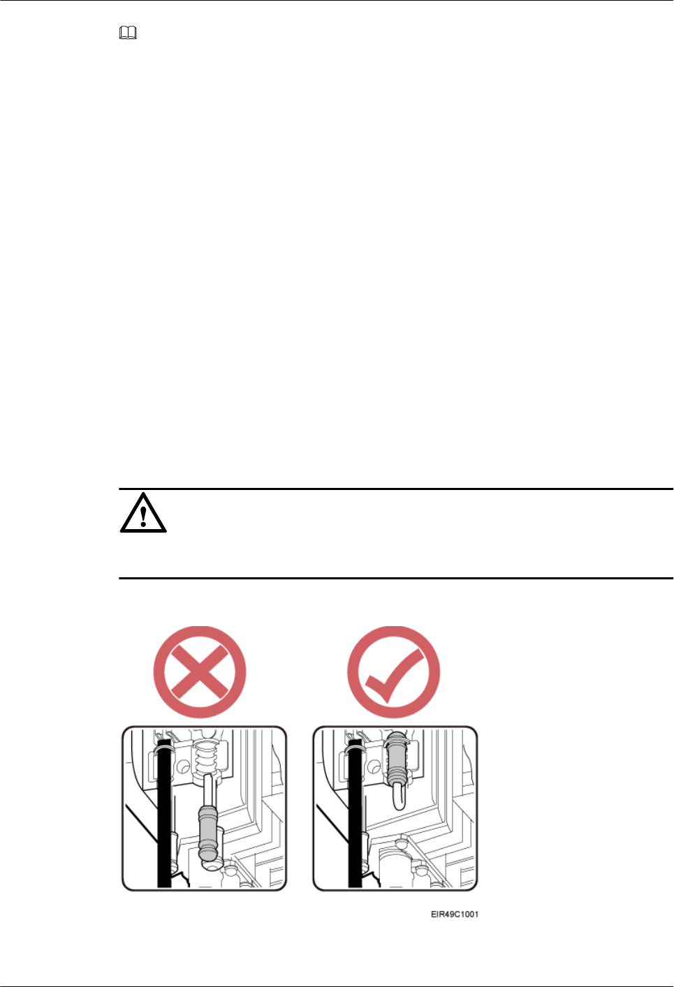
NOTE
The connection mode of CPRI_E0 port is the same to that of CPRI_E1 port on pRRU3907, and this chapter
uses CPRI_E0 as an example.
----End
Follow-up Procedure
1. Route the cable by following the instructions in section 9.4.1 Cabling Requirements
and use cable ties to bind the cable.
2. Label the installed cable. For details, see section 14.5 Attaching a Sign Plate Label.
9.4.9 Closing the Cover Plate of a pRRU3907 Cabling Cavity
This section describes the procedure for closing the cover plate of a pRRU3907 cabling
cavity.
Procedure
Step 1 Insert waterproof blocks into vacant cable troughs in the cabling cavity, as shown in Figure
9-23. Figure 9-23 is for reference only and vacant cable troughs must be blocked based on
onsite requirements.
NOTICE
Ensure that cables and waterproof blocks are properly inserted into troughs.
Figure 9-23 Correct placement of waterproof blocks
DBS3900 LampSite
Installation Guide 9 Installing a pRRU3907
Issue 07 (2015-12-30) Huawei Proprietary and Confidential
Copyright © Huawei Technologies Co., Ltd.
184
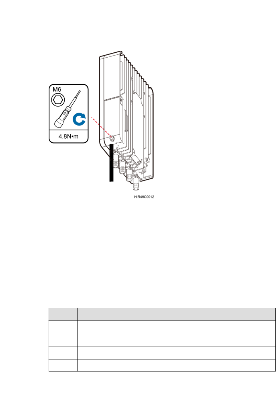
Step 2 Close the cover plate of the pRRU3907 cabling cavity, and use an M6 inner hexagon
screwdriver to tighten the screw on the cover plate to 4.8 N·m (42.48 lbf·in.), as shown in
Figure 9-24.
Figure 9-24 Closing the cover plate of a pRRU3907 cabling cavity
Step 3 Take off the ESD gloves, and pack up all tools.
----End
9.5 Checking the pRRU3907 Hardware Installation
pRRU3907 hardware installation checking includes hardware and cable installation checking.
Table 9-6 lists the hardware installation checking items.
Table 9-6 Hardware installation checking list
No. Item
1 The installation position of each device strictly complies with the engineering
design and meets clearance requirements. Sufficient space is reserved for
equipment maintenance.
2 The pRRU3907 is securely installed.
3 The cover plate is securely installed on the RRU cabling cavity.
DBS3900 LampSite
Installation Guide 9 Installing a pRRU3907
Issue 07 (2015-12-30) Huawei Proprietary and Confidential
Copyright © Huawei Technologies Co., Ltd.
185
No. Item
4 Waterproof blocks are securely installed in vacant cable troughs of the
pRRU3907 cabling cavity, and the cover plate of the cabling cavity is securely
installed. In addition, vacant RF ports are covered with dustproof caps and the
caps are tightened.
5 Labels are correct, legible, and complete at both ends of each cable, feeder, and
jumper.
Table 9-7 lists the check items of the signal cable connection.
Table 9-7 Checklist for the signal cable connection
No. Item
1 The connectors of the signal cables must securely connected.
2 The connectors of the signal cables are intact.
3 The signal cables are intact.
4 The cable ties are evenly spaced. The signal cables are bound neatly with cable
ties to proper tightness, and arranged at even intervals in the same direction.
5 The extra length of the cable ties is cut and removed. The cut surfaces of the
indoor cables are smooth and have no sharp edges.
6 The cable layout facilitates maintenance and expansion.
7 Correct and clear labels are attached to both ends of the signal cables.
Table 9-8 lists the checking items for other cable connections.
Table 9-8 Checklist for other cable connections
No. Item
1 The connectors of the other cables must securely connected.
2 Labels on the cables are legible and bound based on the engineering
requirements. The cables must be bound tightly and neatly. The sheaths of the
cables must not be damaged.
3 Positions for routing the cables must meet requirements of the engineering
design.
4 There are no connectors or joints on each PGND cable. None of PGND cables
can be short-circuited or reversely connected. In addition, these cables are not
damaged or broken.
5 PGND cables are separately bound from other cables.
DBS3900 LampSite
Installation Guide 9 Installing a pRRU3907
Issue 07 (2015-12-30) Huawei Proprietary and Confidential
Copyright © Huawei Technologies Co., Ltd.
186
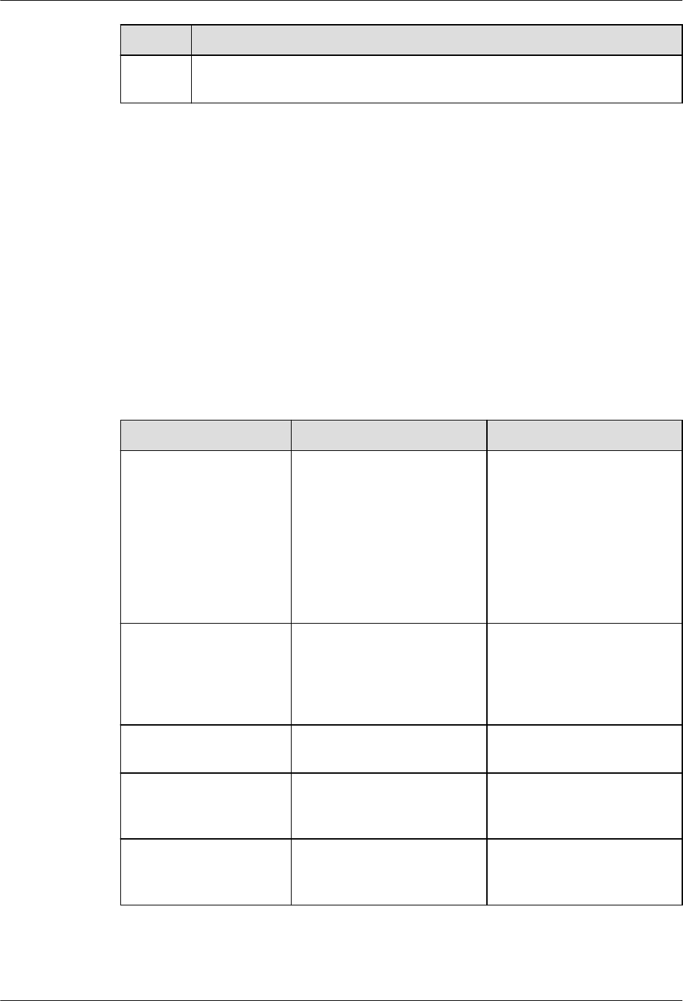
No. Item
6 The protection grounding of the pRRU3907 and the surge protection grounding
of the building share one group of ground conductors.
9.6 Powering on the pRRU3907
This section describes the power-on check on the pRRU3907 after the pRRU3907 hardware is
installed and checked.
Context
After the RHUB and pRRUs are installed and connected to each other, power on them no
matter whether the BBU is installed.
Procedure
Step 1 Power on the pRRU3907. Wait 3 to 5 minutes, check the status of the 3GPP indicator on the
pRRU3907.
If the 3GPP Indicator... Because... Then...
Blinks white at 4 Hz The pRRU3907 is loading
software, configuring data, or
it is not running.
Wait until the software is
loaded. If the loading is not
completed in five minutes,
power off the pRRU3907 and
check whether the data
configuration file is correct.
After the fault is rectified,
power on the pRRU3907
again.
Blinks white at 0.5 Hz
(on for 1s and off for 1s)
The pRRU3907 is working
properly and does not
transmit power.
Check whether the services
have been configured and
power amplification have
been enabled on the
pRRU3907.
Is steady white The cell is set up and
transmits power properly.
No further action is required.
Is steady orange. There is power input, but the
hardware is faulty.
Power off the pRRU3907,
rectify the hardware fault, and
then power it on again.
Blinks orange at 0.5 Hz
(on for 1s and off for 1s)
A minor alarm (indicating an
HDLC link disconnection, for
example) is generated.
Troubleshoot based on the
alarm information.
DBS3900 LampSite
Installation Guide 9 Installing a pRRU3907
Issue 07 (2015-12-30) Huawei Proprietary and Confidential
Copyright © Huawei Technologies Co., Ltd.
187

If the 3GPP Indicator... Because... Then...
Is off The board is not powered on. Turn off the power supply
switch and check whether the
power input is normal. If the
power input is normal, check
for and rectify board faults,
and turn on the power supply
switch again.
NOTE
Check the indicator status 30 minutes after the power-on if a pRRU is not connected to any BBU. The pRRU
is considered normally powered on when any indicator on the pRRU is on.
----End
DBS3900 LampSite
Installation Guide 9 Installing a pRRU3907
Issue 07 (2015-12-30) Huawei Proprietary and Confidential
Copyright © Huawei Technologies Co., Ltd.
188
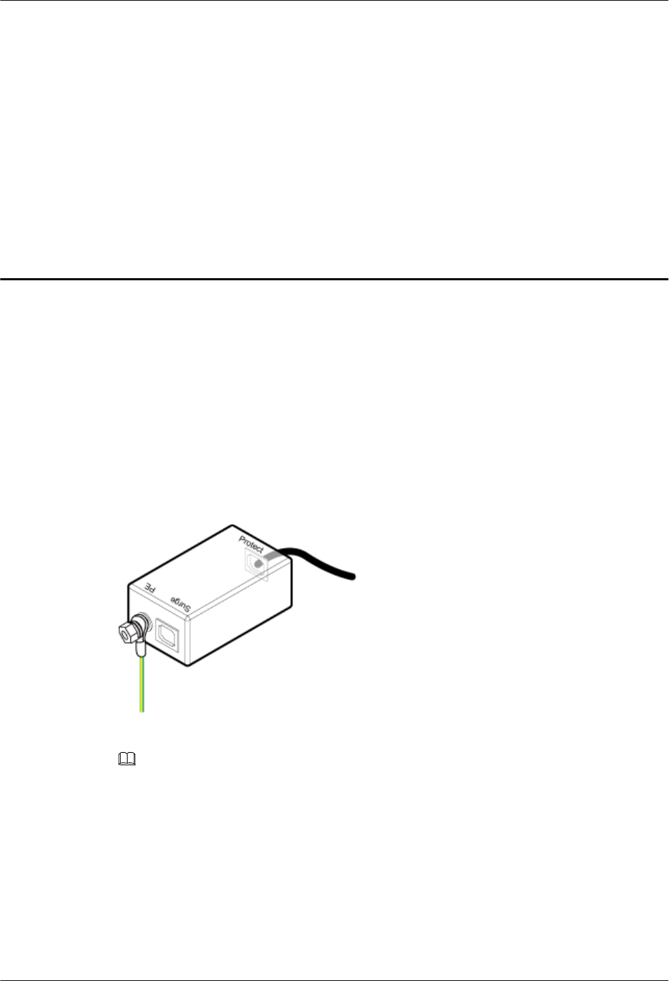
10 (Optional) Installing the PoE Surge
Protector and Cables
This section describes how to install a PoE surge protector and its cables in the cabinet. When
the RHUB, pRRU, and extender are installed outdoors, a PoE surge protector is required to
provide surge protection for the PoE power supply port.
Procedure
Step 1 Connect a PGND cable to the PE ground terminal and an Ethernet cable (about 0.4 m long) to
the Protect port. See Figure 10-1.
Figure 10-1 Installing the PGND Cable and Ethernet Cable (1)
Step 2 Install the PoE surge protector in the cabinet. See Figure 10-2.
NOTE
The Surge port must be installed toward the outside.
DBS3900 LampSite
Installation Guide 10 (Optional) Installing the PoE Surge Protector and Cables
Issue 07 (2015-12-30) Huawei Proprietary and Confidential
Copyright © Huawei Technologies Co., Ltd.
189
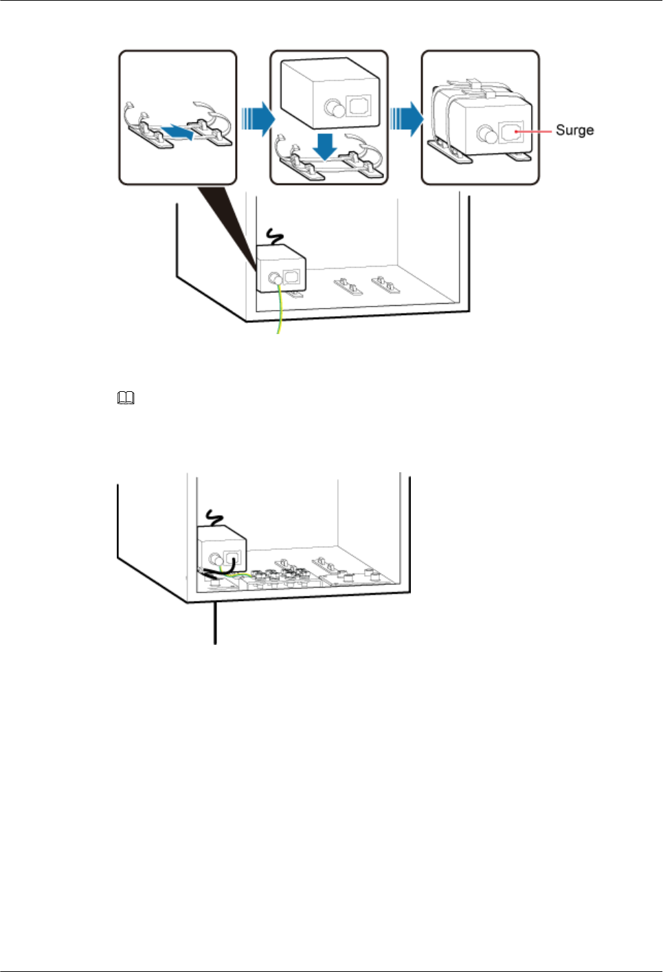
Figure 10-2 Installing the PoE surge protector
Step 3 Connect an Ethernet cable to the Surge port, and the other end of the PGND cable to the
ground terminal on the cabinet. See Figure 10-3.
NOTE
During the installation, bind the Ethernet cables to the side cable bridge on the cabinet.
Figure 10-3 Installing the PGND Cable and Ethernet Cable (2)
----End
DBS3900 LampSite
Installation Guide 10 (Optional) Installing the PoE Surge Protector and Cables
Issue 07 (2015-12-30) Huawei Proprietary and Confidential
Copyright © Huawei Technologies Co., Ltd.
190
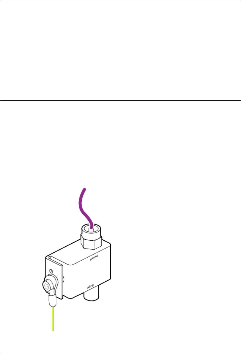
11 (Optional) Installing the RF Surge
Protector and Cables
This section describes how to install an RF surge protector and its cables in the cabinet. When
the pRRU is installed outdoors, an RF surge protector is required to provide surge protection
for the RF port.
Procedure
Step 1 Install the PGND cable and the RF jumper connected to the Protect port. See Figure 11-1.
Figure 11-1 Installing the PGND Cable and RF Jumper (1)
Step 2 Install the RF surge protector in the cabinet. See Figure 11-2.
DBS3900 LampSite
Installation Guide 11 (Optional) Installing the RF Surge Protector and Cables
Issue 07 (2015-12-30) Huawei Proprietary and Confidential
Copyright © Huawei Technologies Co., Ltd.
191
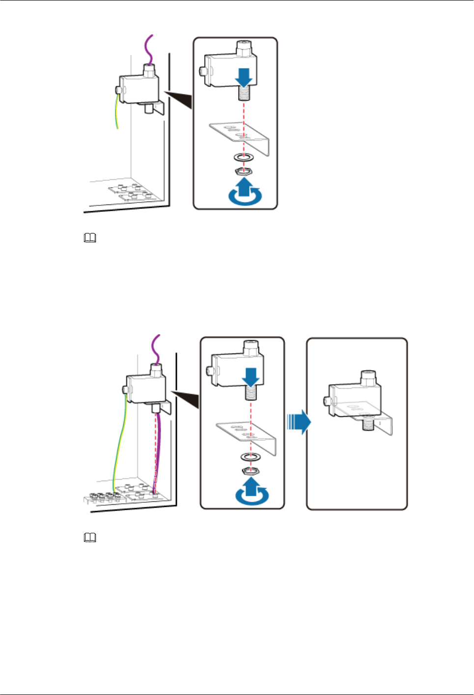
Figure 11-2 Installing the RF surge protector
NOTE
Alternatively, you can remove the fastener on the cabinet, install the RF surge protector and its cables on
the fastener, and then install the combination onto the cabinet.
Step 3 Connect an RF jumper to the Surge port, and the other end of the PGND cable to the ground
terminal on the cabinet. See Figure 11-3.
Figure 11-3 Installing the PGND Cable and RF Jumper (2)
NOTE
lThe cable hole on the cabinet for the RF jumper must be vertical to the Surge port.
lBefore routing all cables through the cable outlet modules at the bottom of the cabinet, wrap the
naked RF jumper by using PVC insulation tape and then apply petroleum jelly.
----End
DBS3900 LampSite
Installation Guide 11 (Optional) Installing the RF Surge Protector and Cables
Issue 07 (2015-12-30) Huawei Proprietary and Confidential
Copyright © Huawei Technologies Co., Ltd.
192

12 (Optional) Installing the Extender
This section describes the Extender installation process.
Context
When an RHUB and a pRRU need extended install, use extender. With the Extender, the
distance of the pRRU and RHUB can be extended by the Extender up to a total distance of
200 m.
The Extender can be installed on a wall or ceiling in the same mode. This section describes
wall-mounted installation as an example.
Only space above and under the Extender is required to be reserved when installing the
Extender. The recommended space for installing the Extender is described as follows:
lAt least 150 mm above the Extender is reserved for cabling.
lAt least 150 mm under the Extender is reserved for cabling.
Procedure
lIndoor scenario:
a. Use a marker to mark the two anchor points according to inter-hole spacing, as
shown in Figure 12-1.
DBS3900 LampSite
Installation Guide 12 (Optional) Installing the Extender
Issue 07 (2015-12-30) Huawei Proprietary and Confidential
Copyright © Huawei Technologies Co., Ltd.
193
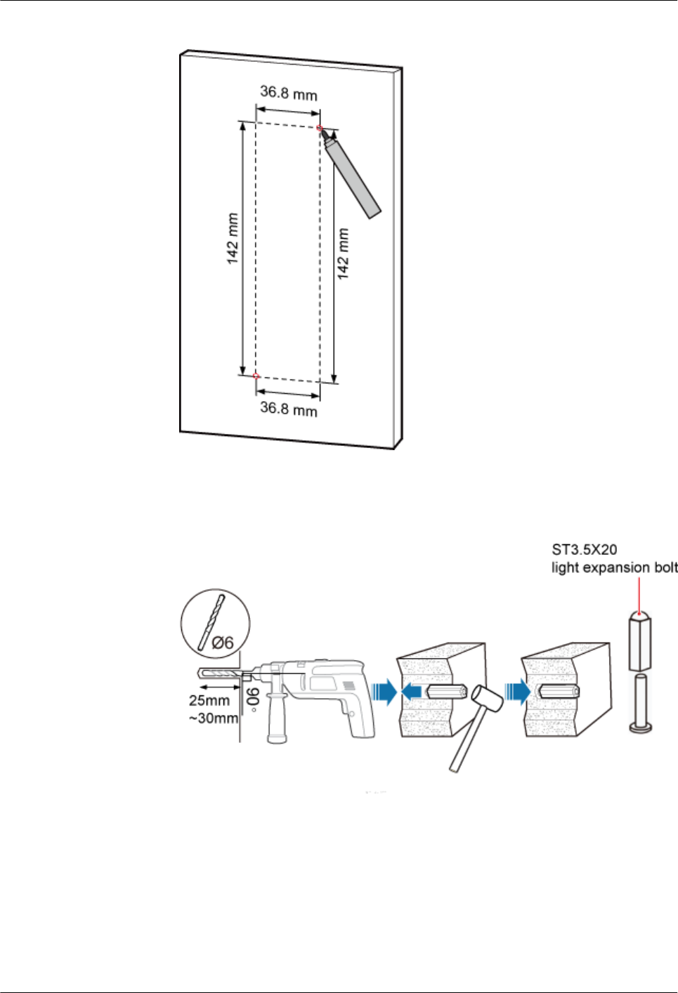
Figure 12-1 Marking anchor points
b. Drill holes at the anchor points, and install expansion bolt assemblies, as shown in
Figure 12-2. The diameter of the hole is 6 mm, and the depth is 25 mm to 30 mm.
Figure 12-2 Drilling holes and installing expansion bolts
c. Place the Extender in the corresponding position and use an M4 Phillips
screwdriver to tighten the screws to 1.4 N•m, as shown in Figure 12-3.
DBS3900 LampSite
Installation Guide 12 (Optional) Installing the Extender
Issue 07 (2015-12-30) Huawei Proprietary and Confidential
Copyright © Huawei Technologies Co., Ltd.
194
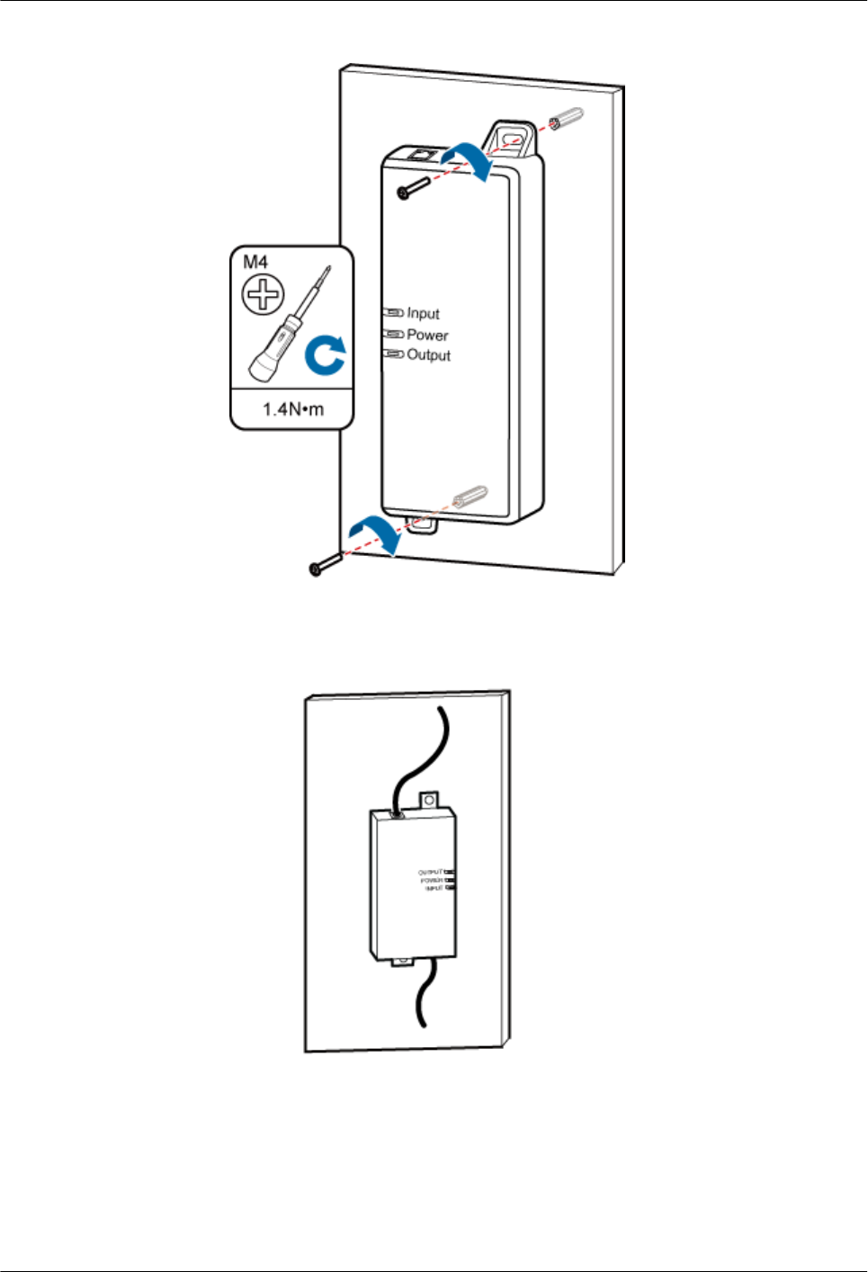
Figure 12-3 Installing Extender
d. Installing the Ethernet cables at the two ends of Extender, as shown in Figure 12-4.
Figure 12-4 Installing the Ethernet cables (1)
lOutdoor:
a. Installing the Ethernet cables at the two ends of Extender, as shown in Figure 12-5.
DBS3900 LampSite
Installation Guide 12 (Optional) Installing the Extender
Issue 07 (2015-12-30) Huawei Proprietary and Confidential
Copyright © Huawei Technologies Co., Ltd.
195
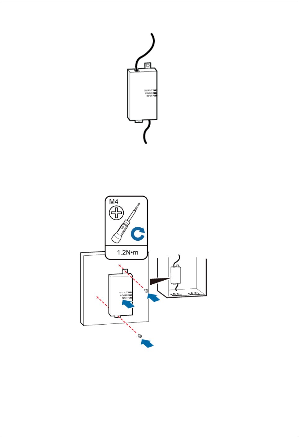
Figure 12-5 Installing the Ethernet cables (2)
b. Install the Extender to the cabinet, and keep the OUTPUT interface on top, as
shown in Figure 12-6.
Figure 12-6 Installing the Extender to the cabinet
----End
DBS3900 LampSite
Installation Guide 12 (Optional) Installing the Extender
Issue 07 (2015-12-30) Huawei Proprietary and Confidential
Copyright © Huawei Technologies Co., Ltd.
196

13 (Optional) Installing the Cabinet and
Cabinet Cables
About This Chapter
This section describes the procedure and precautions for installing a cabinet and cables
connected to it. The cabinet can be installed on the wall, pole, channel steel, angle steel, steel
mesh, or ground by using mounting kits. Vertical and horizontal installation modes are
supported when the cabinet is installed on the steel mesh.
13.1 Installation Clearance Requirements
This section describes the recommended and minimum clearances for a cabinet.
13.2 Mounting Bracket and Attachment Plate
This section describes mounting brackets and attachment plates for installing a cabinet.
13.3 Installing a Cabinet
This section describes the procedure and precautions for installing a cabinet.
13.4 Installing Cabinet Cables
This chapter describes the procedure for installing cabinet cables.
DBS3900 LampSite
Installation Guide 13 (Optional) Installing the Cabinet and Cabinet Cables
Issue 07 (2015-12-30) Huawei Proprietary and Confidential
Copyright © Huawei Technologies Co., Ltd.
197
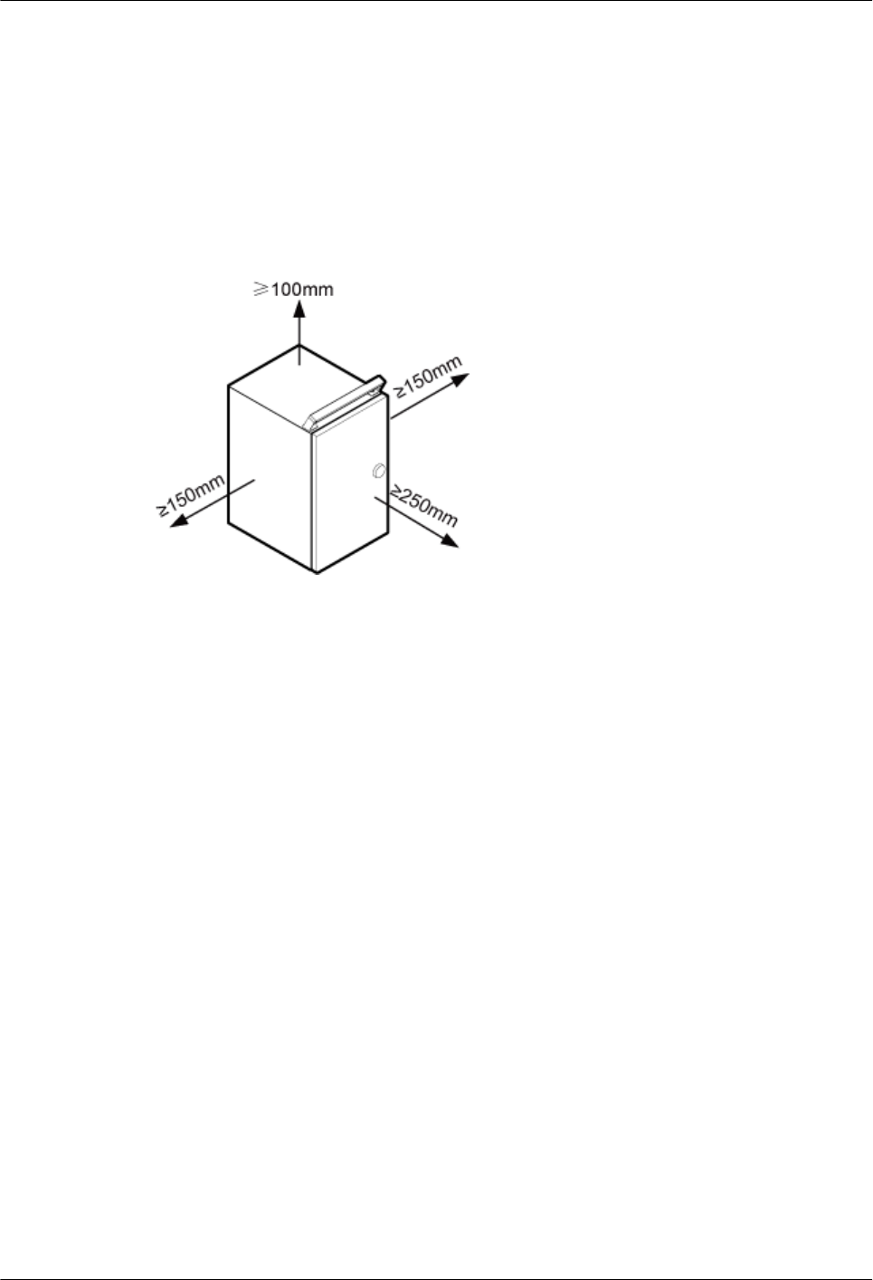
13.1 Installation Clearance Requirements
This section describes the recommended and minimum clearances for a cabinet.
When installing a cabinet, the following clearance requirements should be met.
Figure 13-1 show the recommended clearances for installing a cabinet.
Figure 13-1 Clearances for installing a cabinet
The recommended clearance for installing a cabinet is described as follows:
lAt least 100 mm above the cabinet is reserved for maintenance.
lAt least 150 mm on the left of the cabinet is reserved for maintenance.
lAt least 150 mm on the right of the cabinet is reserved for maintenance.
lAt least 250 mm in front of the cabinet is reserved for maintenance.
13.2 Mounting Bracket and Attachment Plate
This section describes mounting brackets and attachment plates for installing a cabinet.
13.2.1 Mounting Bracket
This section describes mounting brackets for installing a cabinet.
Mounting Bracket for the Cabinet
Figure 13-2 shows the mounting bracket for the cabinet.
DBS3900 LampSite
Installation Guide 13 (Optional) Installing the Cabinet and Cabinet Cables
Issue 07 (2015-12-30) Huawei Proprietary and Confidential
Copyright © Huawei Technologies Co., Ltd.
198
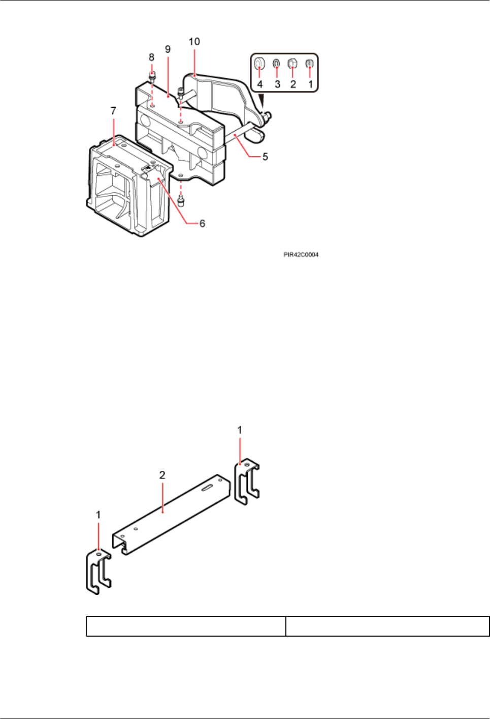
Figure 13-2 Mounting bracket for the cabinet
(1) Plastic cap (2) Standard M10
nut
(3) Spring washer (4) Thick flat washer (5) Square-neck bolt
(6) Hoist clamp on
the main bracket
(7) Main bracket (8) Inner hexagon
screw
(9) Pole installation
bracket
(10) Auxiliary
bracket
Mounting Bracket for the Metal Grid
Figure 13-3 shows the mounting bracket for the metal grid.
Figure 13-3 Mounting bracket for the metal grid
(1) Clamping jaw (2) Horizontal bar
13.2.2 Attachment Plate
This section describes attachment plates for installing a cabinet.
DBS3900 LampSite
Installation Guide 13 (Optional) Installing the Cabinet and Cabinet Cables
Issue 07 (2015-12-30) Huawei Proprietary and Confidential
Copyright © Huawei Technologies Co., Ltd.
199
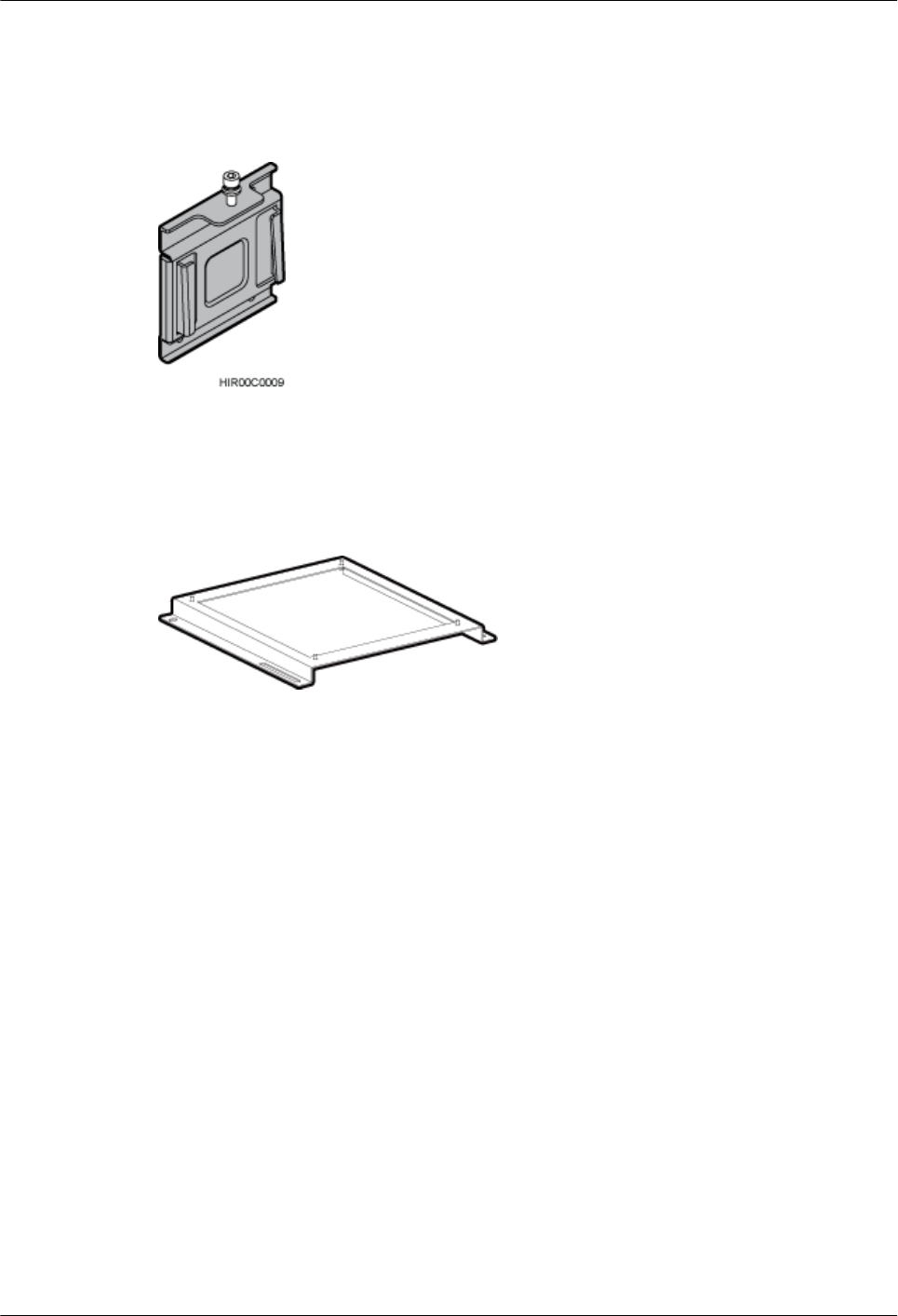
Attachment Plate on the Cabinet Side
Figure 13-4 shows the attachment plate on the cabinet side.
Figure 13-4 Attachment plate on the cabinet side
Attachment Plate at the Cabinet Bottom
Figure 13-5 shows the attachment plate at the cabinet bottom.
Figure 13-5 Attachment plate at the cabinet bottom
13.3 Installing a Cabinet
This section describes the procedure and precautions for installing a cabinet.
13.3.1 Installing the Cabinet on a Wall
This section describes the procedure and precautions for installing the cabinet on a wall.
Procedure
Step 1 Disassemble the cabinet mounting brackets, as shown in Figure 13-6.
DBS3900 LampSite
Installation Guide 13 (Optional) Installing the Cabinet and Cabinet Cables
Issue 07 (2015-12-30) Huawei Proprietary and Confidential
Copyright © Huawei Technologies Co., Ltd.
200
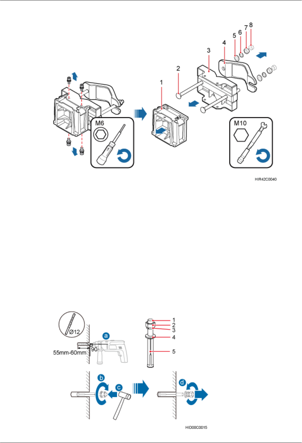
Figure 13-6 Disassembling the mounting brackets
(1) Main bracket (2) Square-neck bolt (3) Pole installation bracket (4) Auxiliary bracket
(5) Flat washer (6) Spring washer (7) Nut (8) Plastic cap
1. Use an M6 inner hexagon torque screwdriver to remove the four inner hexagon screws
on the pole installation bracket, and remove the main bracket from the pole installation
bracket.
2. Use an M10 torque wrench to loosen the nuts on the two square-neck bolts, and remove
the plastic cap, nuts, spring washers, flat washers, square-neck bolts, and pole
installation bracket from the auxiliary bracket.
Step 2 Drill holes at the anchor points, and then insert expansion anchor bolt assemblies, as shown
inFigure 13-7.
Figure 13-7 Drilling a hole and inserting expansion anchor bolt assemblies
DBS3900 LampSite
Installation Guide 13 (Optional) Installing the Cabinet and Cabinet Cables
Issue 07 (2015-12-30) Huawei Proprietary and Confidential
Copyright © Huawei Technologies Co., Ltd.
201
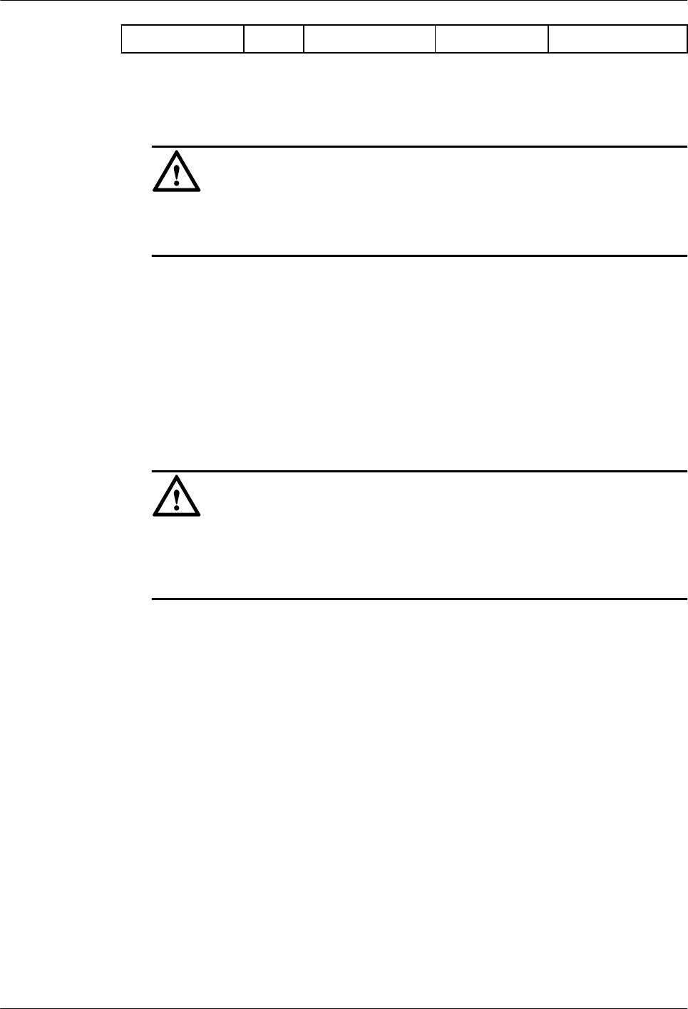
(1) M10x80 bolt (2) Nut (3) Spring washer (4) Flat washer (5) Expansion tube
1. Use a hammer drill with a φ8 bit to drill holes vertically at the marked anchor points.
Ensure that the depth of each hole ranges from 45 mm (1.77 in.) to 50 mm (1.97 in.).
NOTICE
Take proper safety measures to protect your eyes and respiratory tract against the dust
before drilling holes.
2. Use a vacuum cleaner to clear the dust out from inside and around the holes, and
measure the distances between holes. If any of the holes is beyond the acceptable range,
mark a new anchor point and drill a new hole.
3. Tighten the expansion bolts slightly, and place each expansion bolt vertically into each
hole.
4. Use a rubber mallet to pound the expansion anchor bolt until it goes all the way into the
hole.
5. Tighten and then loosen the expansion bolt, and remove the M10 bolt, spring washer,
and flat washer in sequence.
NOTICE
After dismantling an expansion anchor bolt, ensure that the top of the expansion tube is
on the same level as the wall. Otherwise, the device cannot be installed on the wall
evenly and securely.
Step 3 Install the pole installation bracket on the expansion anchor bolts, place the flat washers,
spring washers, and nuts through the expansion anchor bolts in sequence, and then use a 16
mm (0.63 in.) torque socket to tighten the nuts to 30 N·m (265.52 lbf·in.), as shown in Figure
13-8.
DBS3900 LampSite
Installation Guide 13 (Optional) Installing the Cabinet and Cabinet Cables
Issue 07 (2015-12-30) Huawei Proprietary and Confidential
Copyright © Huawei Technologies Co., Ltd.
202
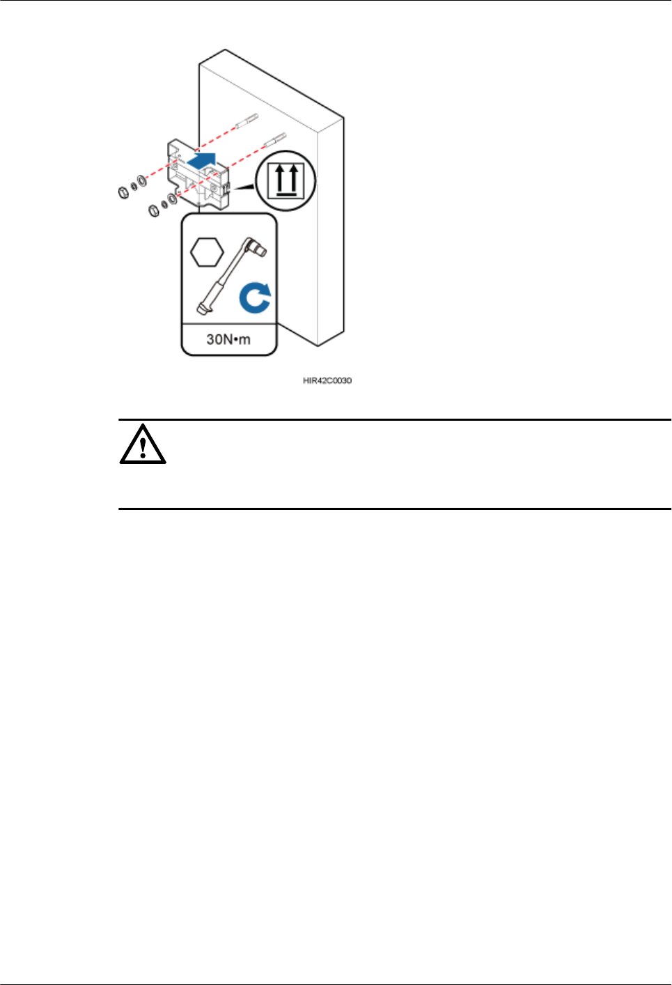
Figure 13-8 Installing the pole installation bracket on the expansion anchor bolts
NOTICE
Verify that the arrows on the pole installation bracket are pointing up.
Step 4 Install the main bracket onto the pole installation bracket, and use an inner hexagon
screwdriver to tighten four M6x16 inner hexagon screws to 5 N·m (44.25 lbf·in.) so that the
main bracket and pole installation bracket are firmly secured, as shown in Figure 13-9.
DBS3900 LampSite
Installation Guide 13 (Optional) Installing the Cabinet and Cabinet Cables
Issue 07 (2015-12-30) Huawei Proprietary and Confidential
Copyright © Huawei Technologies Co., Ltd.
203
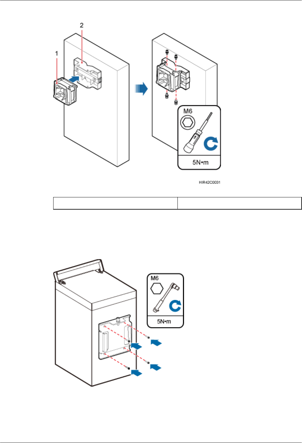
Figure 13-9 Installing the main bracket
(1) Installing the main bracket (2) Installing the main bracket
Step 5 Install the attachment plate on the cabinet side onto the rear of the cabinet, and use a torque
screwdriver to tighten the stainless steel screws on the attachment plate to 5 N·m (44.25
lbf·in.), as shown in Figure 13-10.
Figure 13-10 Installing the attachment plate onto the rear of the cabinet
Step 6 Install the cabinet onto the main bracket, as shown in Figure 13-11.
DBS3900 LampSite
Installation Guide 13 (Optional) Installing the Cabinet and Cabinet Cables
Issue 07 (2015-12-30) Huawei Proprietary and Confidential
Copyright © Huawei Technologies Co., Ltd.
204
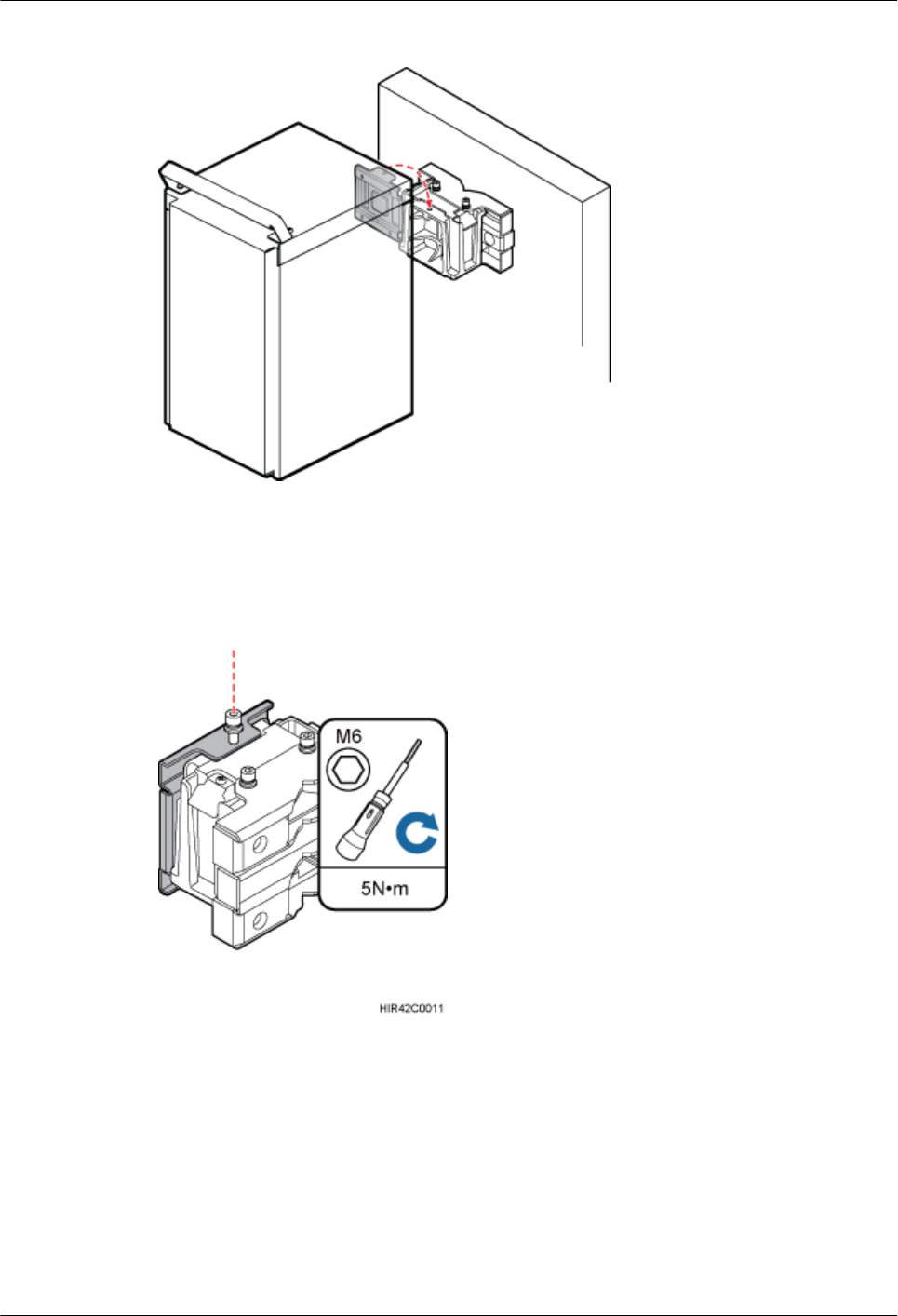
Figure 13-11 Installing the cabinet onto the main bracket
Step 7 Use an inner hexagon screwdriver to tighten the captive screw into the hole of the attachment
plate and main mounting bracket to 5 N·m (44.25 lbf·in.) so that the attachment plate and
main mounting bracket are firmly secured, as shown in Figure 13-12.
Figure 13-12 Securing the captive screw into the connection hole
----End
13.3.2 Installing the Cabinet on a Pole
This section describes the procedure and precautions for installing a cabinet on a pole.
Procedure
Step 1 Install the cabinet mounting brackets, as shown in Figure 13-13.
DBS3900 LampSite
Installation Guide 13 (Optional) Installing the Cabinet and Cabinet Cables
Issue 07 (2015-12-30) Huawei Proprietary and Confidential
Copyright © Huawei Technologies Co., Ltd.
205
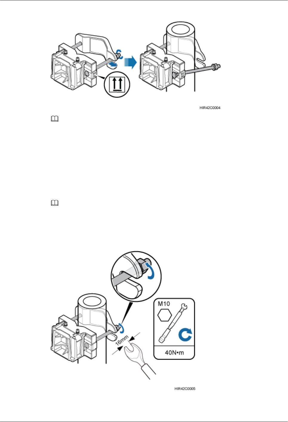
Figure 13-13 Installing the cabinet mounting brackets
NOTE
Verify that the arrows on the mounting brackets are pointing up.
1. Adjust the position of the nut and remove one end of the square-neck bolt from the slot
on the auxiliary bracket.
2. Slide the mounting brackets onto the pole horizontally and insert the square-neck bolt
into the slot.
Step 2 Use a 16 mm (0.63 in.) M10 torque wrench to tighten the nuts to 40 N·m (354.03 lbf·in.) so
that the mounting brackets are secured onto the pole, as shown in Figure 13-14.
NOTE
Tighten the nuts on the two square-neck bolts alternatively. After the main and auxiliary brackets are secured
properly, measure the spacing between the brackets on both sides and ensure that the spacing is the same on
the two sides.
Figure 13-14 Securing the cabinet mounting brackets
Step 3 Install the cabinet onto the main bracket, as shown in Figure 13-15.
DBS3900 LampSite
Installation Guide 13 (Optional) Installing the Cabinet and Cabinet Cables
Issue 07 (2015-12-30) Huawei Proprietary and Confidential
Copyright © Huawei Technologies Co., Ltd.
206
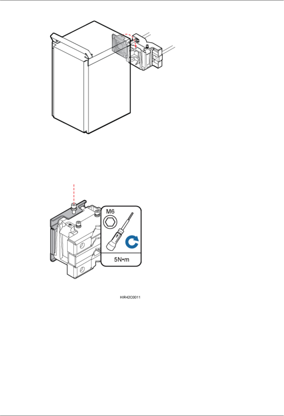
Figure 13-15 Installing the cabinet onto the main bracket
Step 4 Use an inner hexagon torque screwdriver to tighten the captive screw into the holes on the top
of the attachment plate and main bracket to 5 N·m (44.25 lbf·in.) so that the attachment plate
and main bracket are firmly secured, as shown in Figure 13-16.
Figure 13-16 Securing the captive screw into the connection hole
----End
13.3.3 Installing the Cabinet on U-steel
This section describes the procedure and precautions for installing the cabinet on U-steel.
Context
Figure 13-17 shows the top view of the cabinet installed on U-steel.
DBS3900 LampSite
Installation Guide 13 (Optional) Installing the Cabinet and Cabinet Cables
Issue 07 (2015-12-30) Huawei Proprietary and Confidential
Copyright © Huawei Technologies Co., Ltd.
207
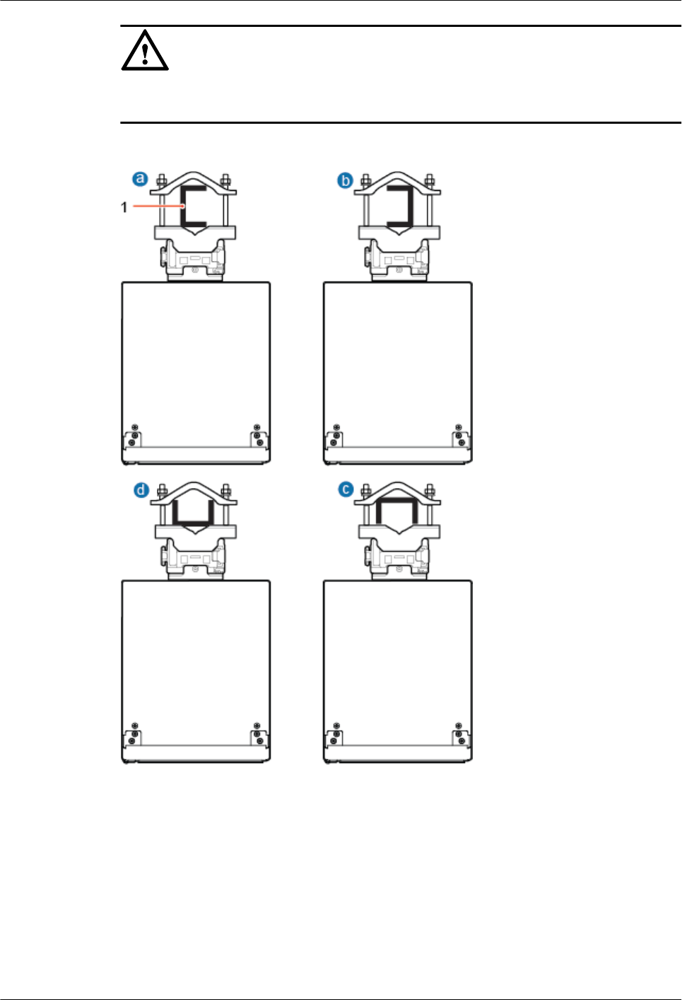
NOTICE
When the width of the narrower edges of the U-steel is less than 40 mm (1.57 in.), only the a
and b modes are supported.
Figure 13-17 Top view of the cabinet
(1) U-steel
Procedure
Step 1 Install the cabinet mounting brackets, as shown in Figure 13-18.
DBS3900 LampSite
Installation Guide 13 (Optional) Installing the Cabinet and Cabinet Cables
Issue 07 (2015-12-30) Huawei Proprietary and Confidential
Copyright © Huawei Technologies Co., Ltd.
208
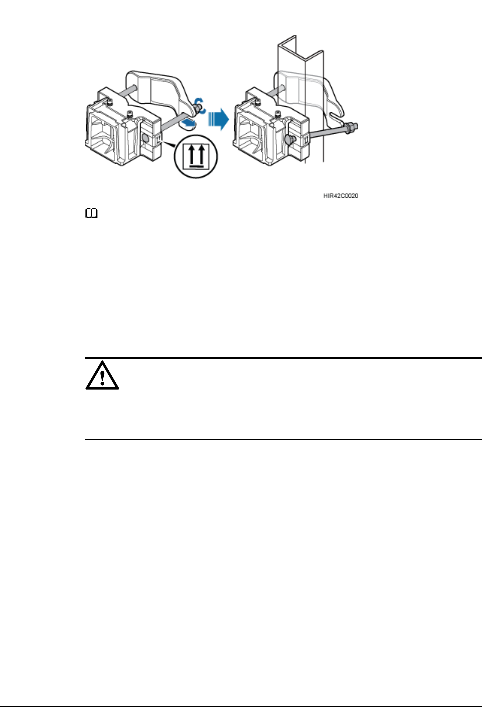
Figure 13-18 Installing the cabinet mounting brackets
NOTE
Verify that the arrows on the mounting brackets are pointing up.
1. Adjust the position of the nut and remove one end of the square-neck bolt from the slot
on the auxiliary bracket.
2. Slide the mounting brackets onto the U-steel horizontally and insert the square-neck bolt
into the slot.
Step 2 Use a 16 mm (0.67 in.) M10 torque wrench to tighten the nuts to 40 N·m (354.03 lbf·in.) so
that the mounting brackets are secured onto the U-steel, as shown in Figure 13-19.
NOTICE
Tighten the nuts on the two square-neck bolts alternatively. After the main and auxiliary
brackets are secured properly, measure the spacing between the brackets on both sides and
ensure that the spacing is the same on the two sides.
DBS3900 LampSite
Installation Guide 13 (Optional) Installing the Cabinet and Cabinet Cables
Issue 07 (2015-12-30) Huawei Proprietary and Confidential
Copyright © Huawei Technologies Co., Ltd.
209

Figure 13-19 Securing the cabinet mounting brackets
Step 3 Install the cabinet onto the main bracket, as shown in Figure 13-20.
Figure 13-20 Installing the cabinet onto the main bracket
Step 4 Use an inner hexagon screwdriver to tighten the captive screw into the holes on the top of the
attachment plate and main bracket to 5 N·m (44.25 lbf·in.) so that the attachment plate and
main bracket are firmly secured, as shown in Figure 13-21.
DBS3900 LampSite
Installation Guide 13 (Optional) Installing the Cabinet and Cabinet Cables
Issue 07 (2015-12-30) Huawei Proprietary and Confidential
Copyright © Huawei Technologies Co., Ltd.
210
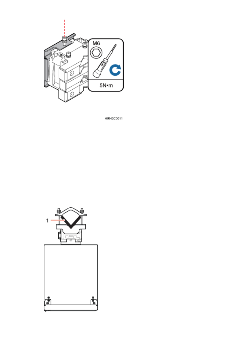
Figure 13-21 Securing the captive screw into the connection hole
----End
13.3.4 Installing the Cabinet on Angle Steel
This section describes the procedure and precautions for installing the cabinet on angle steel.
Context
Figure 13-22 shows the top view of the cabinet installed on angle steel.
Figure 13-22 Top view of the cabinet
(1) Angle steel
Procedure
Step 1 Install the cabinet mounting brackets, as shown in Figure 13-23.
DBS3900 LampSite
Installation Guide 13 (Optional) Installing the Cabinet and Cabinet Cables
Issue 07 (2015-12-30) Huawei Proprietary and Confidential
Copyright © Huawei Technologies Co., Ltd.
211
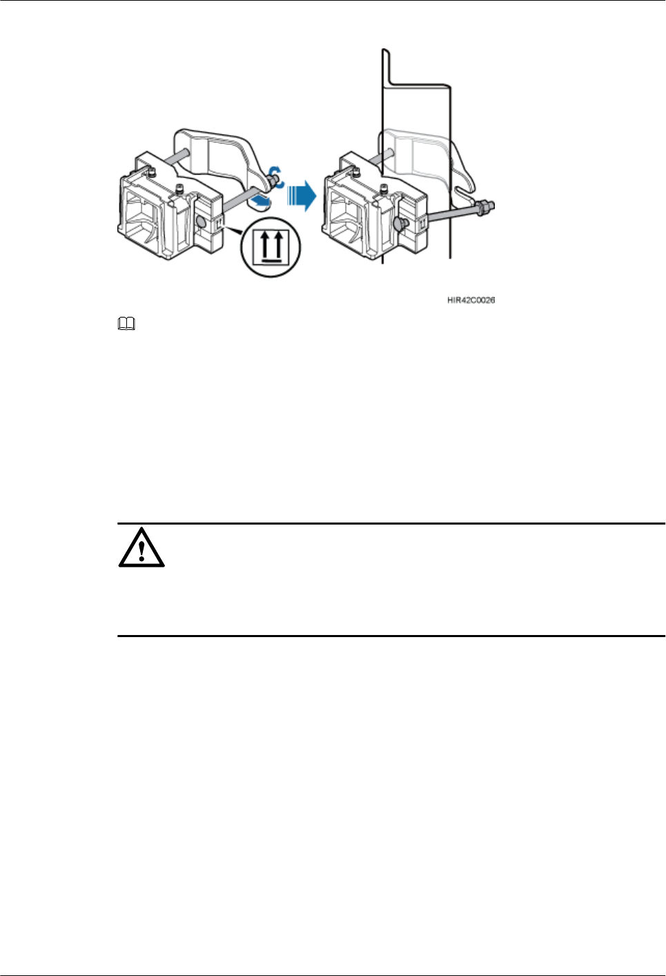
Figure 13-23 Installing the cabinet mounting brackets
NOTE
Verify that the arrows on the mounting brackets are pointing up.
1. Adjust the position of the nut and remove one end of the square-neck bolt from the slot
on the auxiliary bracket.
2. Slide the mounting brackets onto the angle steel horizontally and insert the square-neck
bolt into the slot.
Step 2 Use a 16 mm (0.67 in.) M10 torque wrench to tighten the nuts to 40 N·m (354.03 lbf·in.) so
that the mounting brackets are secured onto the angle steel, as shown in Figure 13-24.
NOTICE
Tighten the nuts on the two square-neck bolts alternatively. After the main and auxiliary
brackets are secured properly, measure the spacing between the brackets on both sides and
ensure that the spacing is the same on the two sides.
DBS3900 LampSite
Installation Guide 13 (Optional) Installing the Cabinet and Cabinet Cables
Issue 07 (2015-12-30) Huawei Proprietary and Confidential
Copyright © Huawei Technologies Co., Ltd.
212
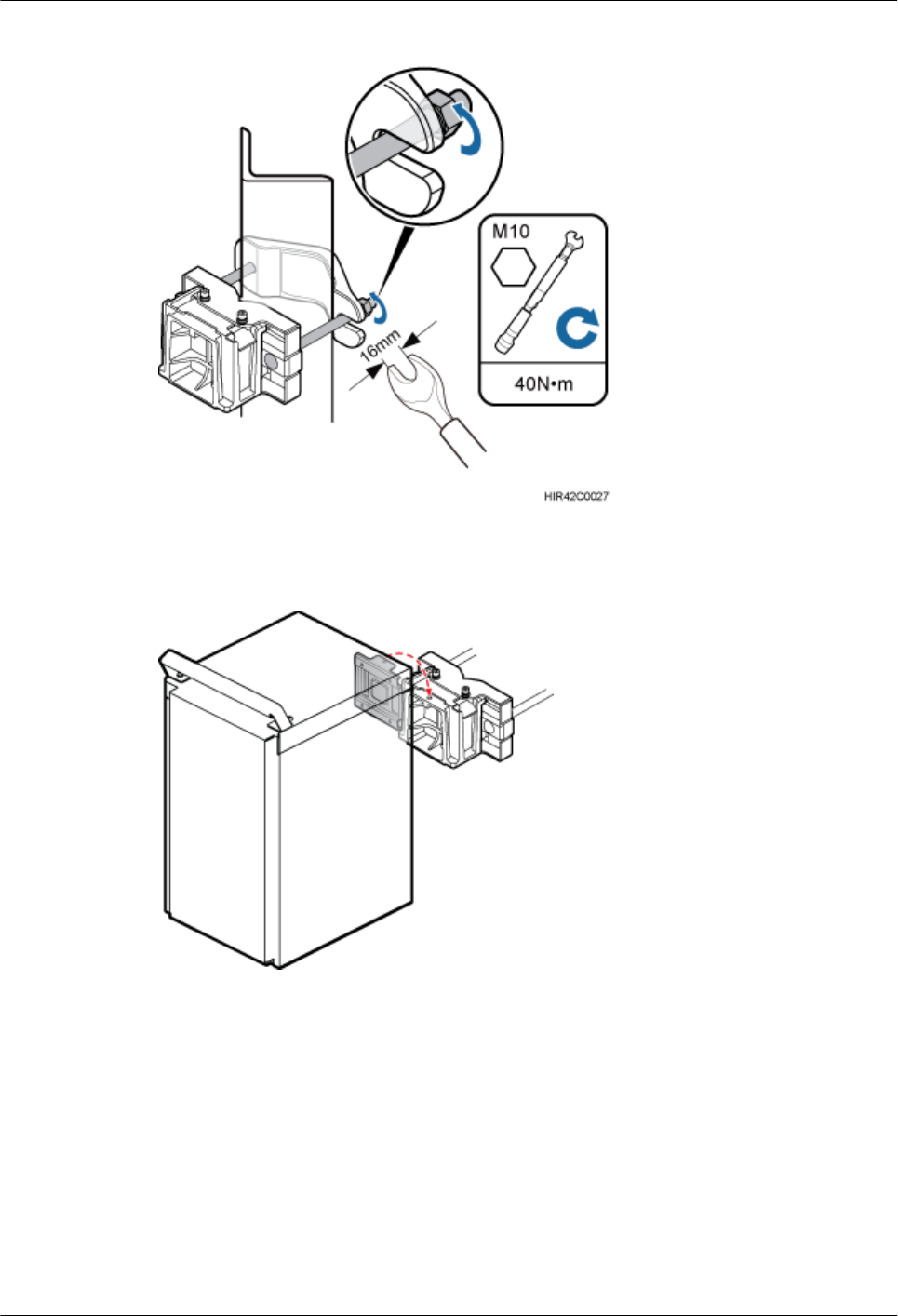
Figure 13-24 Securing the cabinet mounting brackets
Step 3 Install the cabinet onto the main bracket, as shown in Figure 13-25.
Figure 13-25 Installing the cabinet onto the main bracket
Step 4 Use an inner hexagon screwdriver to tighten the captive screw into the holes on the top of the
attachment plate and main bracket to 5 N·m (44.25 lbf·in.) so that the attachment plate and
main bracket are firmly secured, as shown in Figure 13-26.
DBS3900 LampSite
Installation Guide 13 (Optional) Installing the Cabinet and Cabinet Cables
Issue 07 (2015-12-30) Huawei Proprietary and Confidential
Copyright © Huawei Technologies Co., Ltd.
213
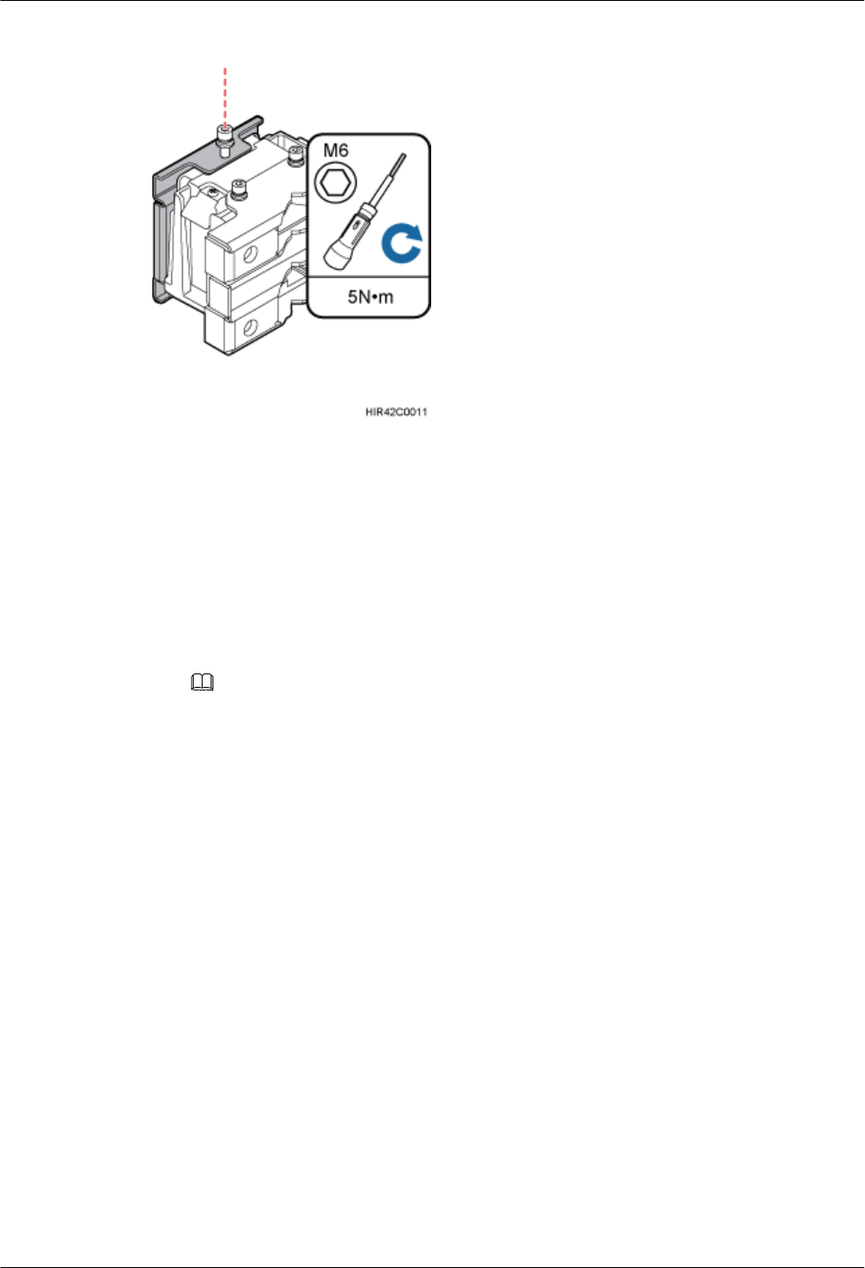
Figure 13-26 Securing the captive screw into the connection hole
----End
13.3.5 Installing the Cabinet on Metal Grid
This section describes the procedure and precautions for installing the cabinet on metal grid.
The cabinet can be vertically or horizontally installed on the metal grid.
Installing the cabinet vertically
1. Install the mounting bracket onto the metal grid, as shown in Figure 13-27.
NOTE
The mounting bracket is recommended to install onto the metal grid close to the round hole.
DBS3900 LampSite
Installation Guide 13 (Optional) Installing the Cabinet and Cabinet Cables
Issue 07 (2015-12-30) Huawei Proprietary and Confidential
Copyright © Huawei Technologies Co., Ltd.
214

Figure 13-27 Installing the mounting bracket onto the metal grid
(1) Metal grid A (2) Round hole (3) Oblong hole
2. Install the cabinet onto the metal grid, as shown in Figure 13-28.
DBS3900 LampSite
Installation Guide 13 (Optional) Installing the Cabinet and Cabinet Cables
Issue 07 (2015-12-30) Huawei Proprietary and Confidential
Copyright © Huawei Technologies Co., Ltd.
215
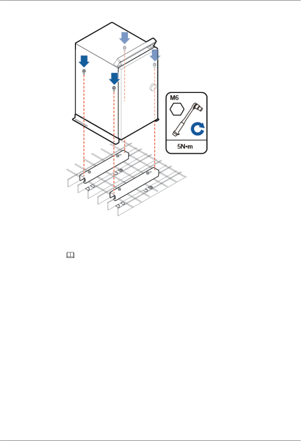
Figure 13-28 Installing the cabinet onto the metal grid
Installing the cabinet horizontally
1. Install the mounting bracket onto the metal grid, as shown in Figure 13-29.
NOTE
The mounting bracket is recommended to install onto the metal grid close to the round hole.
DBS3900 LampSite
Installation Guide 13 (Optional) Installing the Cabinet and Cabinet Cables
Issue 07 (2015-12-30) Huawei Proprietary and Confidential
Copyright © Huawei Technologies Co., Ltd.
216
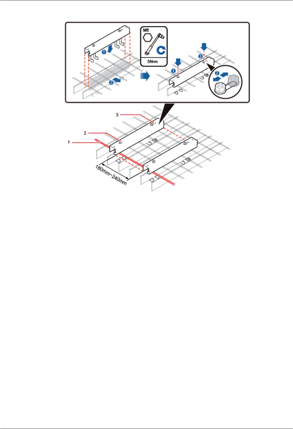
Figure 13-29 Installing the mounting bracket onto the metal grid
(1) Metal grid A (2) Round hole (3) Oblong hole
2. Use an hexagon screwdriver to remove the attachment plate from the bottom of the
cabinet, reinstall the attachment plate onto the side of the cabinet, and tighten the four
stainless screws to 5 N·m (44.25 lbf·in.), as shown in Figure 13-30.
DBS3900 LampSite
Installation Guide 13 (Optional) Installing the Cabinet and Cabinet Cables
Issue 07 (2015-12-30) Huawei Proprietary and Confidential
Copyright © Huawei Technologies Co., Ltd.
217
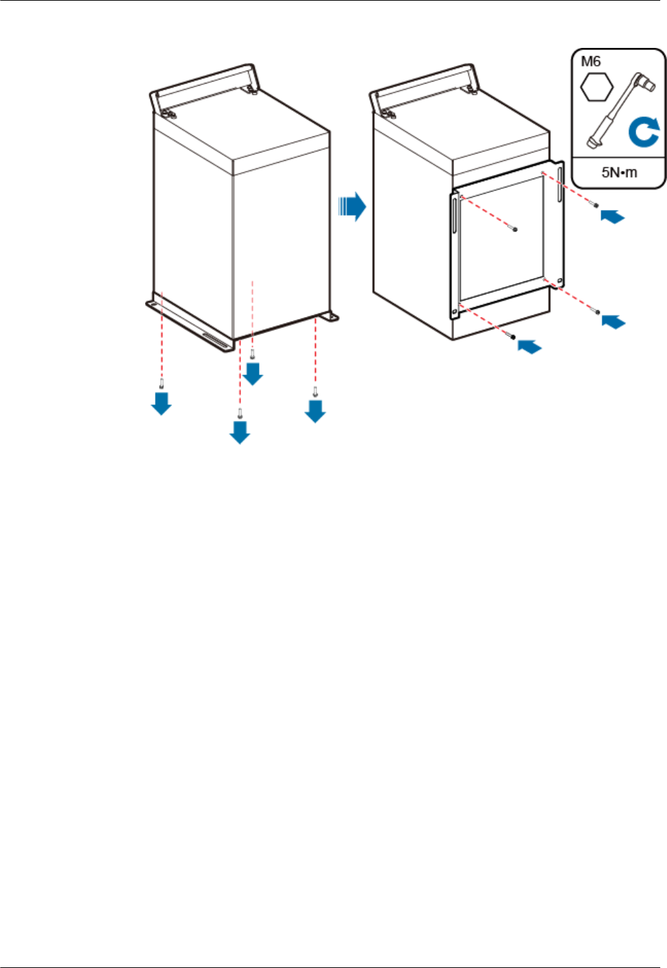
Figure 13-30 Installing the attachment plate onto the side of the cabinet
3. Install the cabinet onto the mounting bracket, as shown in Figure 13-31.
DBS3900 LampSite
Installation Guide 13 (Optional) Installing the Cabinet and Cabinet Cables
Issue 07 (2015-12-30) Huawei Proprietary and Confidential
Copyright © Huawei Technologies Co., Ltd.
218
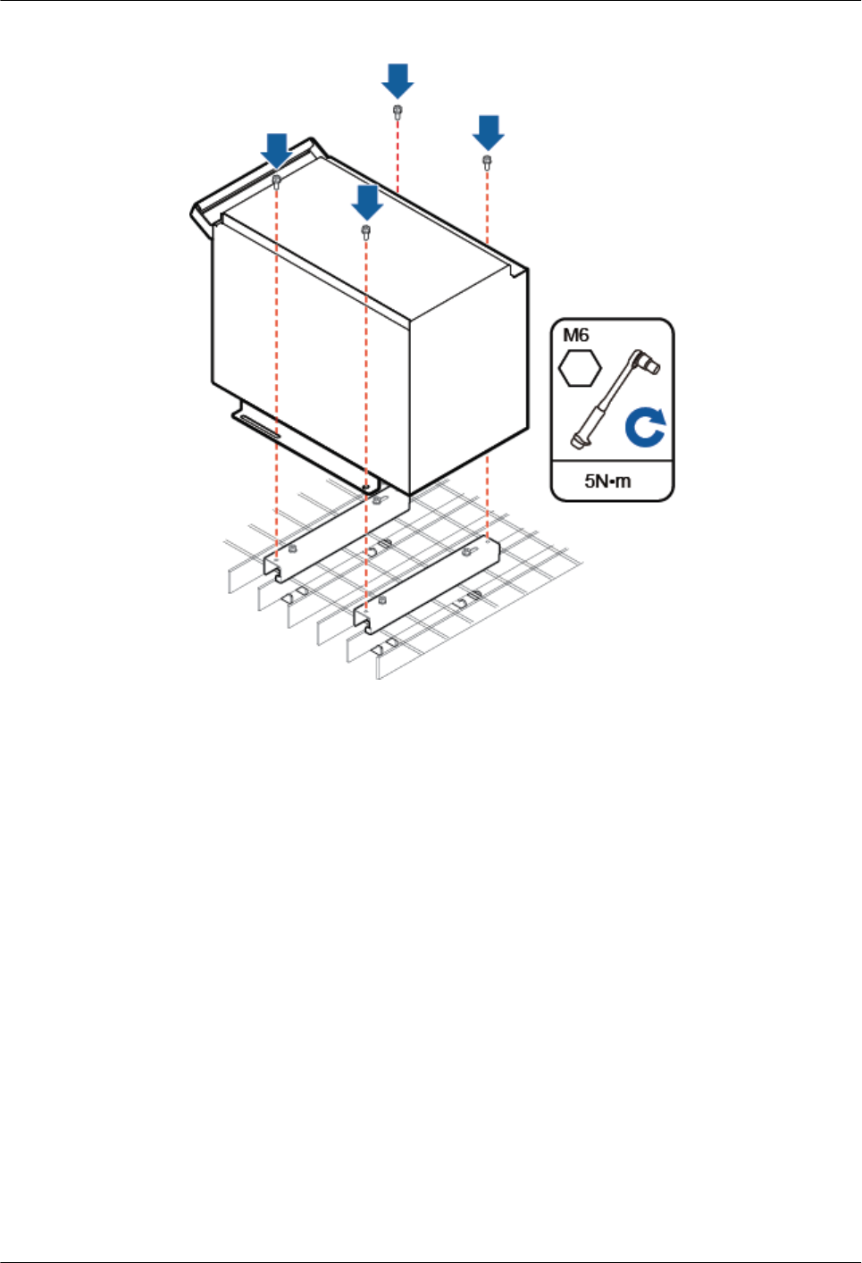
Figure 13-31 Installing the cabinet onto the mounting bracket
13.3.6 Installing the Cabinet on the Floor
This section describes the procedure and precautions for installing the cabinet on the floor.
Procedure
Step 1 Keep the horizontal bar of the steel mesh mounting kit clinging to the floor, use a level to
verify that the marking-off template is placed horizontally, and then use a marker to mark
anchor points, as shown in Figure 13-32.
DBS3900 LampSite
Installation Guide 13 (Optional) Installing the Cabinet and Cabinet Cables
Issue 07 (2015-12-30) Huawei Proprietary and Confidential
Copyright © Huawei Technologies Co., Ltd.
219
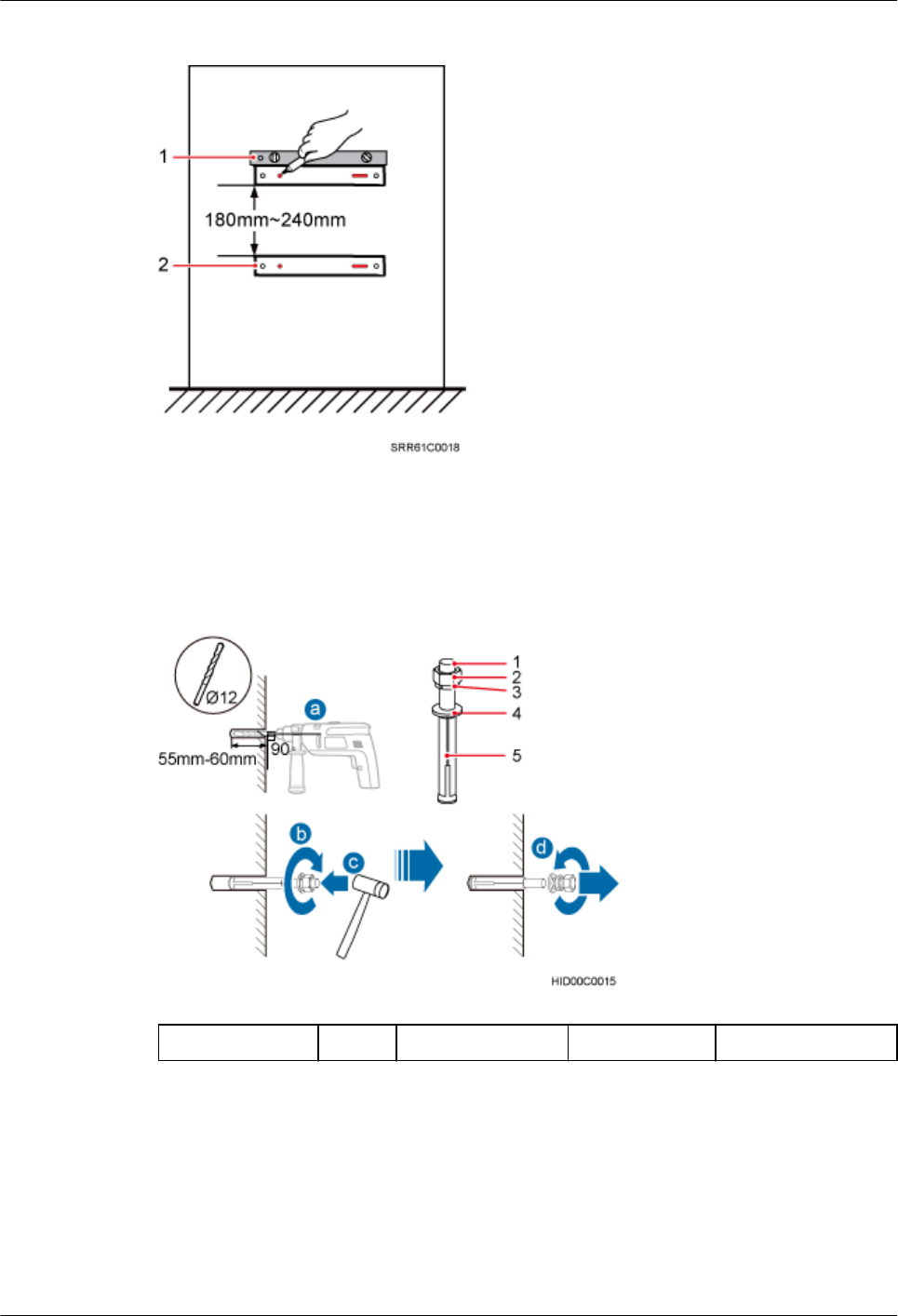
Figure 13-32 Marking anchor points
(1) Level (2) Mounting bracket for the metal grid
Step 2 Drill holes at the anchor points, and then insert expansion anchor bolt assemblies, as shown in
Figure 13-33.
Figure 13-33 Drilling a hole and inserting expansion anchor bolt assemblies
(1) M10x80 bolt (2) Nut (3) Spring washer (4) Flat washer (5) Expansion tube
1. Use a hammer drill with a Ф12 bit to drill holes vertically at the marked anchor points
with the depth ranging from 55 mm (2.17 in.) to 60 mm (2.36 in.), use a vacuum cleaner
to clear the dust out from inside and around the holes, and measure the distances between
holes. If any of the holes is beyond the acceptable range, mark a new anchor point and
drill a new hole.
DBS3900 LampSite
Installation Guide 13 (Optional) Installing the Cabinet and Cabinet Cables
Issue 07 (2015-12-30) Huawei Proprietary and Confidential
Copyright © Huawei Technologies Co., Ltd.
220
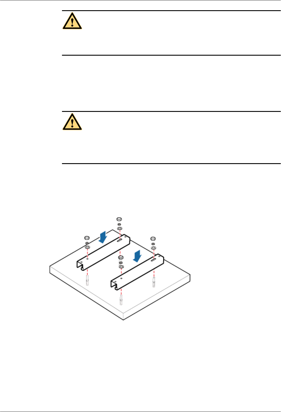
CAUTION
Take proper safety measures to protect your eyes and respiratory tract against the dust
before drilling holes.
2. Tighten the expansion anchor bolts slightly and place one vertically into each hole.
3. Use a rubber mallet to pound the expansion anchor bolt until it goes all the way into the
hole.
4. Tighten and then loosen the expansion bolt, and remove the M10 bolt, spring washer,
and flat washer in sequence.
CAUTION
After dismantling an expansion anchor bolt, ensure that the top of the expansion tube is
on the same level as the wall. Otherwise, the device cannot be installed on the wall
evenly and securely.
Step 3 Fit the horizontal bar of the steel mesh mounting kit on the expansion anchor bolts, place the
flat washers, spring washers, and nuts through the expansion anchor bolts in sequence, and
then use a 16 mm (0.63 in.) torque socket to tighten the nuts to 30 N·m (265.52 lbf·in.), as
shown in Figure 13-34.
Figure 13-34 Installing mounting bracket on the expansion anchor bolts
Step 4 Use a hexagon screwdriver to remove the attachment plate from the bottom of the cabinet,
reinstall the attachment plate onto the side of the cabinet, and tighten the four stainless screws
to 5 N·m (44.25 lbf·in.), as shown in Figure 13-35.
DBS3900 LampSite
Installation Guide 13 (Optional) Installing the Cabinet and Cabinet Cables
Issue 07 (2015-12-30) Huawei Proprietary and Confidential
Copyright © Huawei Technologies Co., Ltd.
221
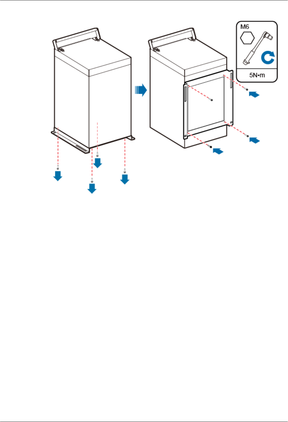
Figure 13-35 Installing the attachment plate onto the side of the cabinet
Step 5 Install the cabinet onto the mounting bracket, as shown in Figure 13-36.
DBS3900 LampSite
Installation Guide 13 (Optional) Installing the Cabinet and Cabinet Cables
Issue 07 (2015-12-30) Huawei Proprietary and Confidential
Copyright © Huawei Technologies Co., Ltd.
222
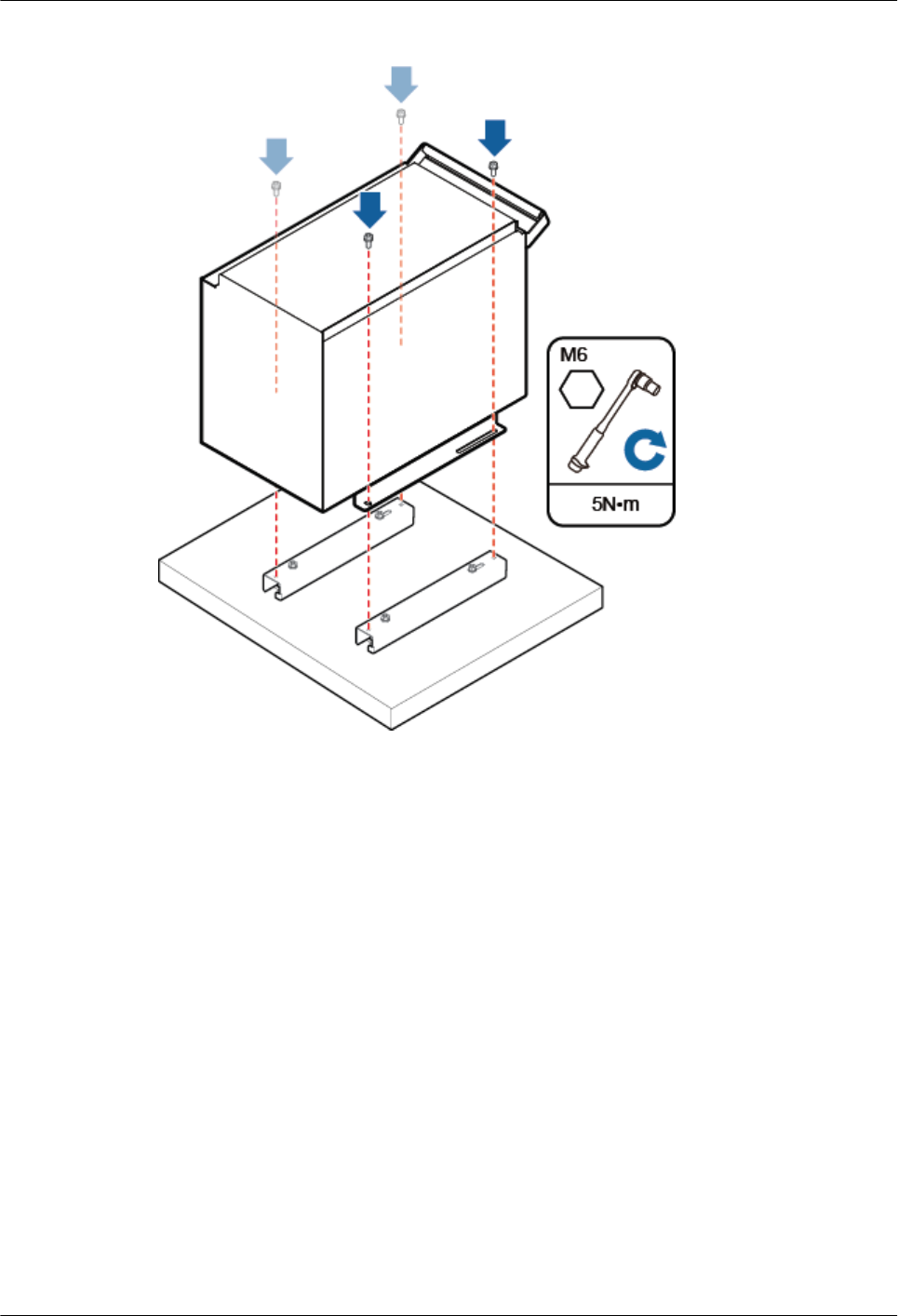
Figure 13-36 Installing the cabinet onto the mounting bracket
----End
13.4 Installing Cabinet Cables
This chapter describes the procedure for installing cabinet cables.
13.4.1 Cable Connections
This section describes the cable connections for the cabinet.
lAt horizontal installation, ensure that all cable outlets can be protected against the rain.
lAfter cable connections are complete, apply firestop putty to all cable outlets on the
cabinet for waterproofing.
Figure 13-37 shows the cable connections for the cabinet.
DBS3900 LampSite
Installation Guide 13 (Optional) Installing the Cabinet and Cabinet Cables
Issue 07 (2015-12-30) Huawei Proprietary and Confidential
Copyright © Huawei Technologies Co., Ltd.
223
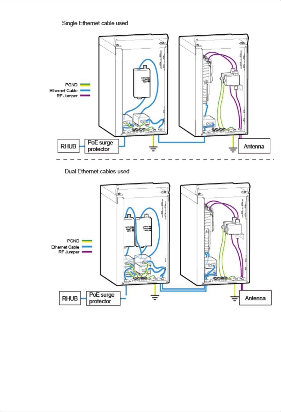
Figure 13-37 Cable connections when a pRRU3901 is installed
DBS3900 LampSite
Installation Guide 13 (Optional) Installing the Cabinet and Cabinet Cables
Issue 07 (2015-12-30) Huawei Proprietary and Confidential
Copyright © Huawei Technologies Co., Ltd.
224
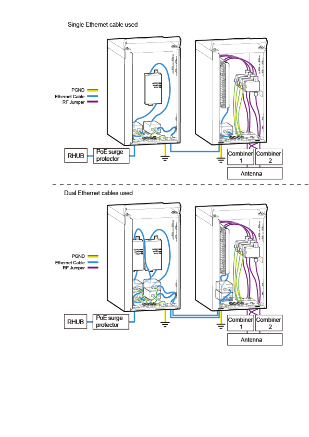
Figure 13-38 Cable connections when a pRRU3902 is installed
DBS3900 LampSite
Installation Guide 13 (Optional) Installing the Cabinet and Cabinet Cables
Issue 07 (2015-12-30) Huawei Proprietary and Confidential
Copyright © Huawei Technologies Co., Ltd.
225
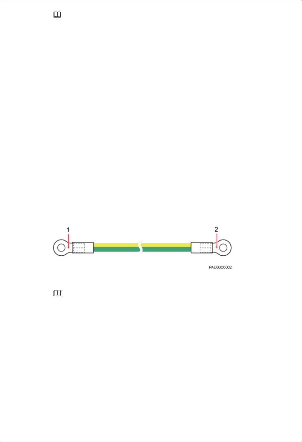
NOTE
lFor details about installation of RHUB Ethernet cables in the cabinet, see 6.4.6 Installing Ethernet
Cable. For details about installation of pRRU3901 Ethernet cables in the cabinet, see 7.5.7 Installing an
Ethernet Cable. For details about installation of pRRU3902 Ethernet cables in the cabinet, see 8.4.5
Installing a pRRU3902 Ethernet Cable.
lFor details about installation of pRRU3901 RF jumpers in the cabinet, see 7.5.8 Installing an RF
jumpers (Optional). For details about installation of pRRU3902 RF jumpers in the cabinet, see 8.4.7
Installing a pRRU3902 RF Jumper (Optional).
lFor details about installation of PoE surge protector PGND cables, see 10 (Optional) Installing the PoE
Surge Protector and Cables. For details about installation of RF surge protector PGND cables, see 11
(Optional) Installing the RF Surge Protector and Cables.
13.4.2 Installing a PGND Cable for the Cabinet
This section describes the procedure for installing a PGND cable for the cabinet.
Prerequisites
The OT terminals at both ends of the PGND cable are prepared.
Context
The yellow and green or green PGND cable is a single cable. The cross-sectional area of the
PGND cable is 6 mm2 (0.009 in.2). Both ends of the cable are OT terminals, as shown in
Figure 13-39.
Figure 13-39 Exterior of a PGND cable
(1) OT terminal (6mm2, M5) (2) OT terminal (6mm2, M6)
NOTE
lIf the PGND cable is provided by the customer, a copper-core cable with a minimum cross-sectional area
of 6 mm2 (0.009 in.2) or 10 AWG is recommended.
lThe OT terminals at both ends of the PGND cable are assembled at the site.
lThe M6 OT terminal has the default size. You can replace it with another OT terminal of the expected
size based on the site requirement.
lEnsure proper grounding of the cabinet using a PGND cable.
lWhen installing the PGND cable, tightly press the OT terminal in the correct direction, as shown in
Figure 13-40.
DBS3900 LampSite
Installation Guide 13 (Optional) Installing the Cabinet and Cabinet Cables
Issue 07 (2015-12-30) Huawei Proprietary and Confidential
Copyright © Huawei Technologies Co., Ltd.
226
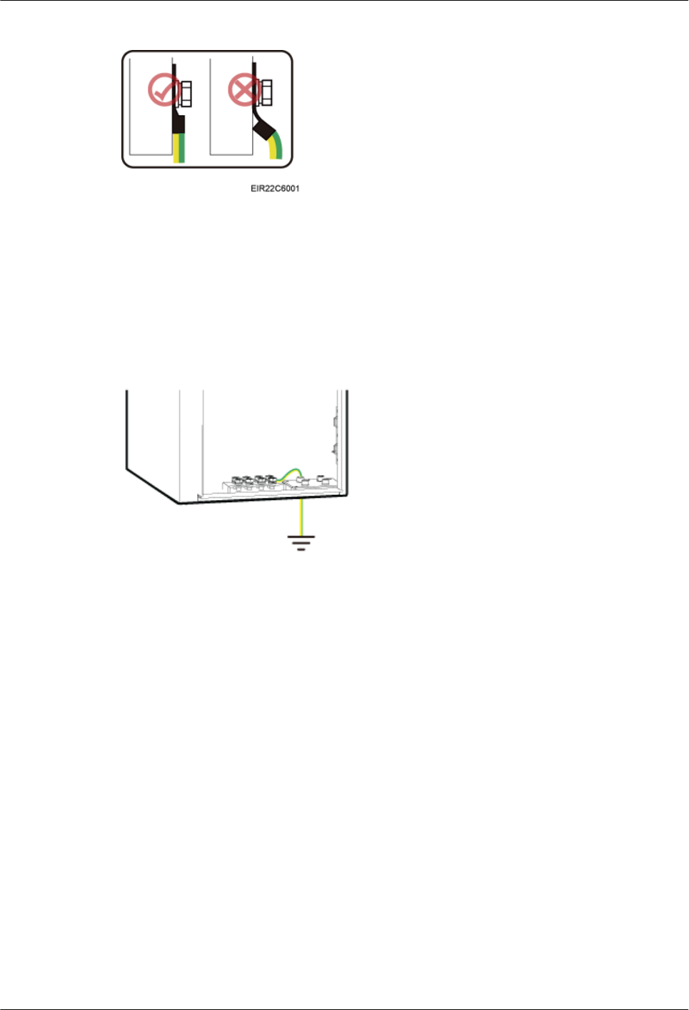
Figure 13-40 Correct direction of an OT terminal for the PGND cable
Procedure
Step 1 Use a torque screwdriver or Phillips screwdriver to secure the M4 OT terminal at one end of
the PGND cable to the ground screw on the cabinet panel with a torque of 1.4 N•m. If the OT
terminal is a one-hole OT terminal, connect it to the ground screw on the lower part of the
cabinet panel, as shown in Figure 13-41.
Figure 13-41 Installing the PGND cable for the cabinet
Step 2 Use a torque screwdriver or Phillips screwdriver to secure the M6 OT terminal at one end of
the PGND cable to the wiring terminal on the ground bar at the site with a torque of 1.4 N•m.
----End
DBS3900 LampSite
Installation Guide 13 (Optional) Installing the Cabinet and Cabinet Cables
Issue 07 (2015-12-30) Huawei Proprietary and Confidential
Copyright © Huawei Technologies Co., Ltd.
227

14 Appendix
About This Chapter
This chapter describes reference information during installation.
14.1 MAC Collection Template
This section describes the MAC collection template for a pRRU3901 with three transmission
ports.
14.2 Assembling a Shielded RJ45 Connector and an Ethernet Cable
This section describes how to assemble a shielded RJ45 connector and an Ethernet cable. A
straight-through cable is used as an example.
14.3 DBS3900 LampSite Engineering Label
This section describes the content and presents the exterior of DBS3900 LampSite
engineering labels.
14.4 Attaching an L-Shaped Label
This section describes the procedure and precautions to be taken for attaching an L-shaped
label.
14.5 Attaching a Sign Plate Label
This section describes the procedures and precautions for attaching a sign plate label.
DBS3900 LampSite
Installation Guide 14 Appendix
Issue 07 (2015-12-30) Huawei Proprietary and Confidential
Copyright © Huawei Technologies Co., Ltd.
228
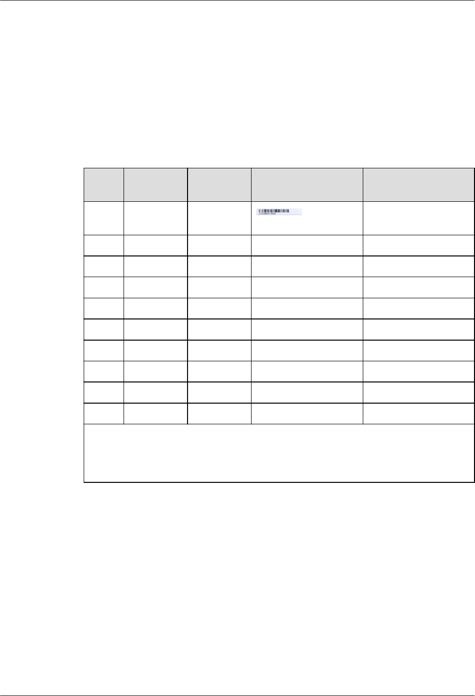
14.1 MAC Collection Template
This section describes the MAC collection template for a pRRU3901 with three transmission
ports.
The MAC collection template is used to record the installation position, MAC address of the
site at the initial installation stage to facilitate subsequent commissioning and maintenance.
Table 14-1 shows the MAC collection template.
Table 14-1 MAC collection template
No. Site
Number
Site Name WIFI MAC Location Information
Sampl
e
01 pRRU3901 xx floor, xx building, xx
mansion
Note: The MAC collection template is essential to the engineering stage and
subsequent maintenance, especially when multiple devices are installed at a short
distance. This is because the template defines the radio network to access. Maintain
this template with caution.
14.2 Assembling a Shielded RJ45 Connector and an
Ethernet Cable
This section describes how to assemble a shielded RJ45 connector and an Ethernet cable. A
straight-through cable is used as an example.
Context
Figure 14-1 shows the components of an RJ45 connector and an Ethernet cable.
DBS3900 LampSite
Installation Guide 14 Appendix
Issue 07 (2015-12-30) Huawei Proprietary and Confidential
Copyright © Huawei Technologies Co., Ltd.
229
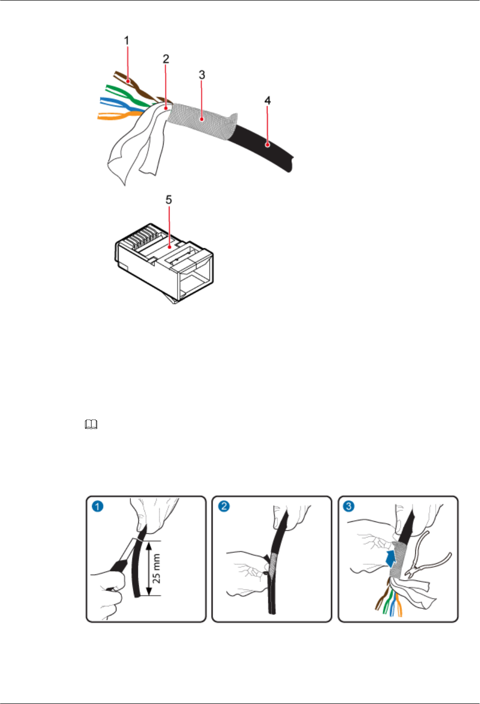
Figure 14-1 Components of an RJ45 connector and an Ethernet cable
(1) Core wire (2) Aluminum foil (3) Braided layer (4) Outer jacket (5) RJ45 connector
Procedure
Step 1 Remove the outer jacket (25 mm) of the Ethernet cable, tip the braided layer outwards evenly,
and cut off the aluminum foil and guard space. See Figure 14-2.
NOTE
lDo not damage the shield layer when removing the jacket.
lDo not damage the insulation layer of the Ethernet cable when removing the shield layer.
Figure 14-2 Removing the jacket of an Ethernet cable
Step 2 Sequence the twisted pair wires neatly by color, and cut the wire end evenly, with a remaining
length of 16 mm. See Figure 14-3.
DBS3900 LampSite
Installation Guide 14 Appendix
Issue 07 (2015-12-30) Huawei Proprietary and Confidential
Copyright © Huawei Technologies Co., Ltd.
230
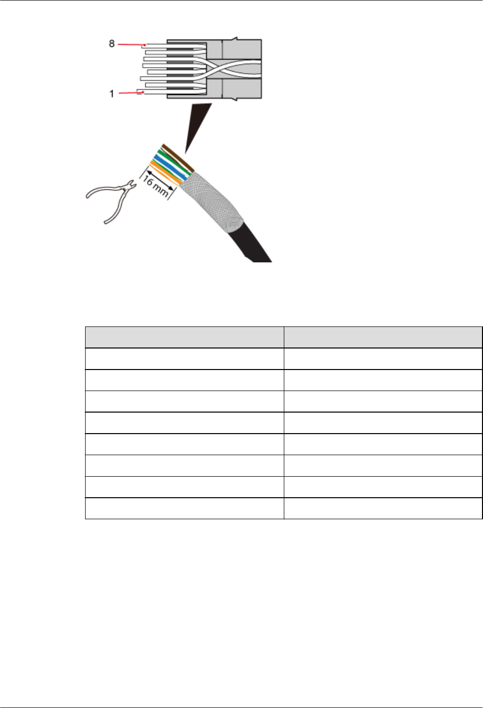
Figure 14-3 Arranging twisted pair wires
Table 14-2 Pin assignment
Pin SN Wire Color
1 White and orange
2 Orange
3 White and green
4 Blue
5 White and blue
6 Green
7 White and brown
8 Brown
Step 3 Insert the sequenced twisted pair wires into the RJ45 connector. See Figure 14-4.
DBS3900 LampSite
Installation Guide 14 Appendix
Issue 07 (2015-12-30) Huawei Proprietary and Confidential
Copyright © Huawei Technologies Co., Ltd.
231
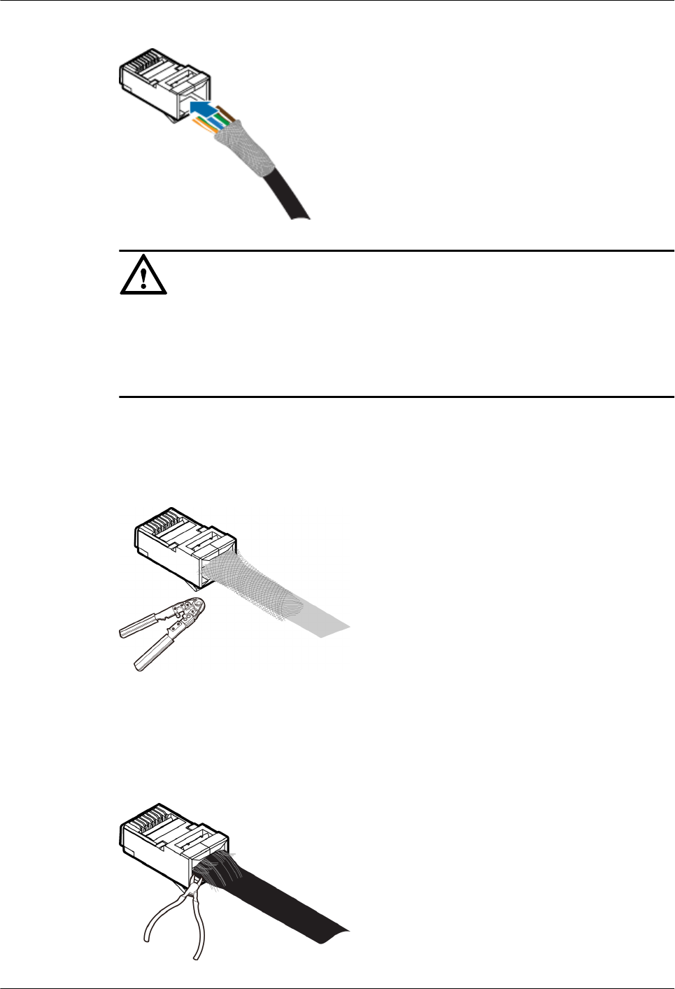
Figure 14-4 Inserting wires into the RJ45 connector
NOTICE
lWhen inserting the wires, ensure that the braided layer that was tipped outwards has
inserted inside the connector.
lObserve the side or front of the RJ45 connector to ensure that the core wires are inserted to
the bottom of the RJ45 connector.
Step 4 Use a crimping tool to crimp the connector. See Figure 14-5.
Figure 14-5 Crimping the connector
Step 5 Use a cable cutter to evenly cut off the protruding braided layer of the connector along the
wire holder. See Figure 14-6.
Figure 14-6 Cutting off the excess braided layer
DBS3900 LampSite
Installation Guide 14 Appendix
Issue 07 (2015-12-30) Huawei Proprietary and Confidential
Copyright © Huawei Technologies Co., Ltd.
232
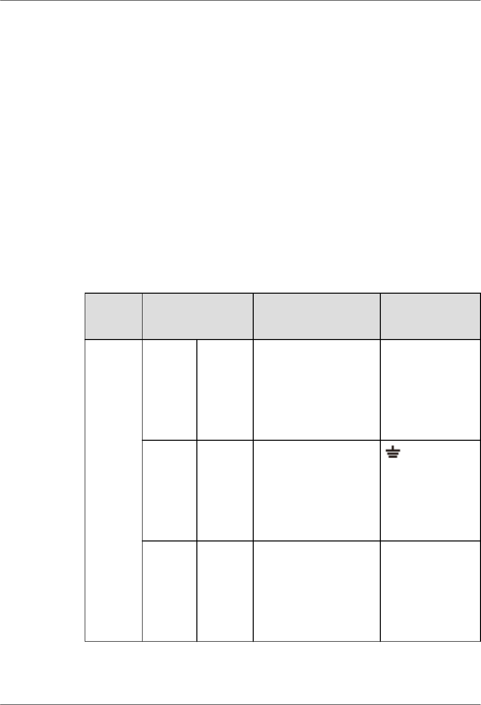
----End
14.3 DBS3900 LampSite Engineering Label
This section describes the content and presents the exterior of DBS3900 LampSite
engineering labels.
Label Content
The DBS3900 LampSite engineering labels include the RHUB power label, RHUB ground
label, RHUB alarm or monitoring label, RHUB optical transmission label, and RHUB
network transmission label, the pRRU power label, pRRU network transmission label, pRRU
antenna label. The engineering labels are used for DBS3900 LampSite units RHUB and
pRRU for indoor scenarios.
By default, blank labels are delivered for DBS3900 LampSite and must be filled in onsite.
Table 14-3 describes the content of engineering labels.
Table 14-3 DBS3900 LampSite Engineering Label Content
NE Label Content Description Corresponding
port on the base
station
RHUB Power
label
RHUBx
PWR
Label for the RHUBx
power cable.
x specifies the number of
RHUBs and cannot exceed
the maximum RHUB
number supported by the
networking.
PWR
Ground
label
RHUBx
PGND
Label for the RHUBx
ground cable.
x specifies the number of
RHUBs and cannot exceed
the maximum RHUB
number supported by the
networking.
Alarm or
monitorin
g label
RHUBx
EXT_AL
M
Label for the RHUBx
alarm cable.
x specifies the number of
RHUBs and cannot exceed
the maximum RHUB
number supported by the
networking.
EXT-ALM
DBS3900 LampSite
Installation Guide 14 Appendix
Issue 07 (2015-12-30) Huawei Proprietary and Confidential
Copyright © Huawei Technologies Co., Ltd.
233

NE Label Content Description Corresponding
port on the base
station
Optical
transmissi
on label
RHUBx
BBU/
RHUBa/
RHUBb
Label for the RHUBx
CPRI cable.
lx specifies the number
of RHUBs and cannot
exceed the maximum
RHUB number
supported by the
networking.
la can be set to 0 or 1. 0
and 1 respectively
correspond to CPRI0
port and CPRI1 port of
the upper-level RHUB.
lb can be set to 0 or 1. 0
and 1 respectively
correspond to CPRI0
port and CPRI1 port of
the lower-level RHUB.
CPRI0 or CPRI1
Network
transmissi
on label
RHUBx
CPRI_Ea
Label for the RHUBx
Ethernet cable.
lx specifies the number
of RHUBs and cannot
exceed the maximum
RHUB number
supported by the
networking.
la can be set to 0 or 1. 0
and 1 respectively
correspond to CPRI_E0
port and CPRI_E1 port
of the pRRU.
CPRI_E0 to
CPRI_E7
pRRU Power
label
pRRUy
PWR
Label for the pRRUy
power cable.
y specifies the number of
pRRUs and cannot exceed
the maximum pRRU
number supported by the
networking.
PWR or CPRI_E0
DBS3900 LampSite
Installation Guide 14 Appendix
Issue 07 (2015-12-30) Huawei Proprietary and Confidential
Copyright © Huawei Technologies Co., Ltd.
234
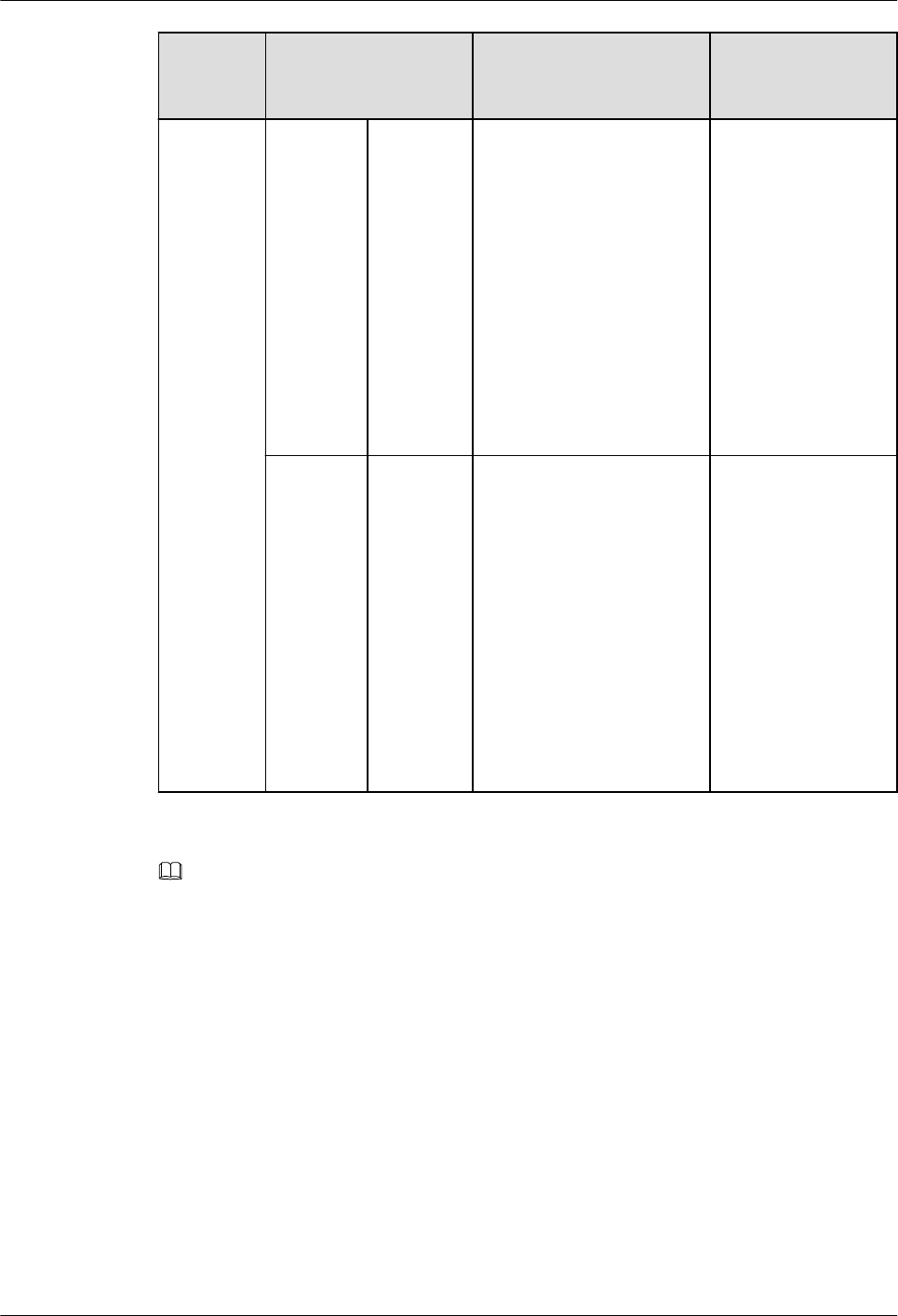
NE Label Content Description Corresponding
port on the base
station
Network
transmissi
on label
pRRUy
CPRI_Ea
Label for the pRRUy
Ethernet cable.
ly specifies the number
of pRRUs and cannot
exceed the maximum
pRRU number
supported by the
networking.
la can be set to 0 to 7,
which respectively
correspond to CPRI_E0
port to CPRI_E7 port of
the RHUB.
CPRI_E0 or
CPRI_E1
Antenna
label
pRRUy
ANTa
Label for the pRRUy RF
Jumper.
ly specifies the number
of pRRUs and cannot
exceed the maximum
pRRU number
supported by the
networking.
la can be set to 0 to 5,
which respectively
correspond to ANT0
port and ANT5 port of
the pRRU.
ANT0 to ANT5
NOTE
lIn the label, RHUB and pRRU identify the specific DBS3900 LampSite NEs.
lIf only one RHUB is deployed, mark it as RHUB0 on the label. If multiple RHUBs are deployed, mark
them in ascending sequence, beginning with RHUB0.
lIf only one pRRU is deployed, mark it as pRRU0 on the label. If multiple pRRUs are deployed, mark
them in ascending sequence, beginning with pRRU0.
lFor details about the maximum number of RHUBs and pRRUs in the DBS3900 LampSite solution, see
Typical Configurations in DBS3900 LampSite Technical Description.
Label Structure
Using the RHUB power label as an example, Figure 14-7 shows the structure of a DBS3900
LampSite engineering label.
DBS3900 LampSite
Installation Guide 14 Appendix
Issue 07 (2015-12-30) Huawei Proprietary and Confidential
Copyright © Huawei Technologies Co., Ltd.
235
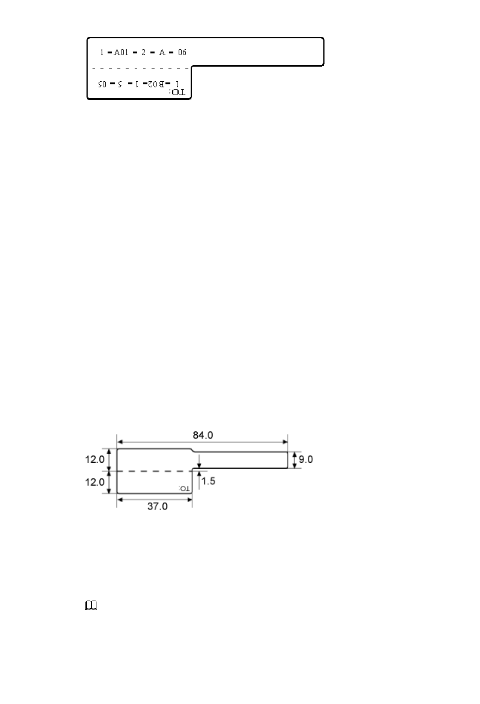
Figure 14-7 Label structure
14.4 Attaching an L-Shaped Label
This section describes the procedure and precautions to be taken for attaching an L-shaped
label.
Context
lThis section applies to Huawei sign plate labels. If other engineering labels in
accordance with local standards are used on site, follow the local standards for attaching
sign plate labels.
lIn the DBS3900 LampSite solution, blank L-Shaped engineering labels are delivered by
default.
lThe L-shaped label is usually used for the signal cable, E1/T1 cable, optical cable, and
power cable. The description in this section takes the Ethernet cable in a base station as
an example.
Procedure
Step 1 Obtain the engineering label to be attached from the whole set of the L-shaped engineering
labels, as shown in Figure 14-8.
Figure 14-8 Engineering label to be attached
Step 2 Attach the long end of the engineering label to the cable in the position 20 mm away from the
connector, and then turn over the long end along the adhesive face. Ensure that the edges of
the turned-over engineering label are in a line, as shown in Figure 14-9.
NOTE
By default, the label is attached in the position 20 mm away from the connector. If required, you can
change the position to make installation faster and more efficient. Consistency and neatness, however,
must be maintained.
Step 3 Adhere the long end to the labeling area. Ensure that the spacing between the cable and the
labeling area is 2 mm to 3 mm.
DBS3900 LampSite
Installation Guide 14 Appendix
Issue 07 (2015-12-30) Huawei Proprietary and Confidential
Copyright © Huawei Technologies Co., Ltd.
236
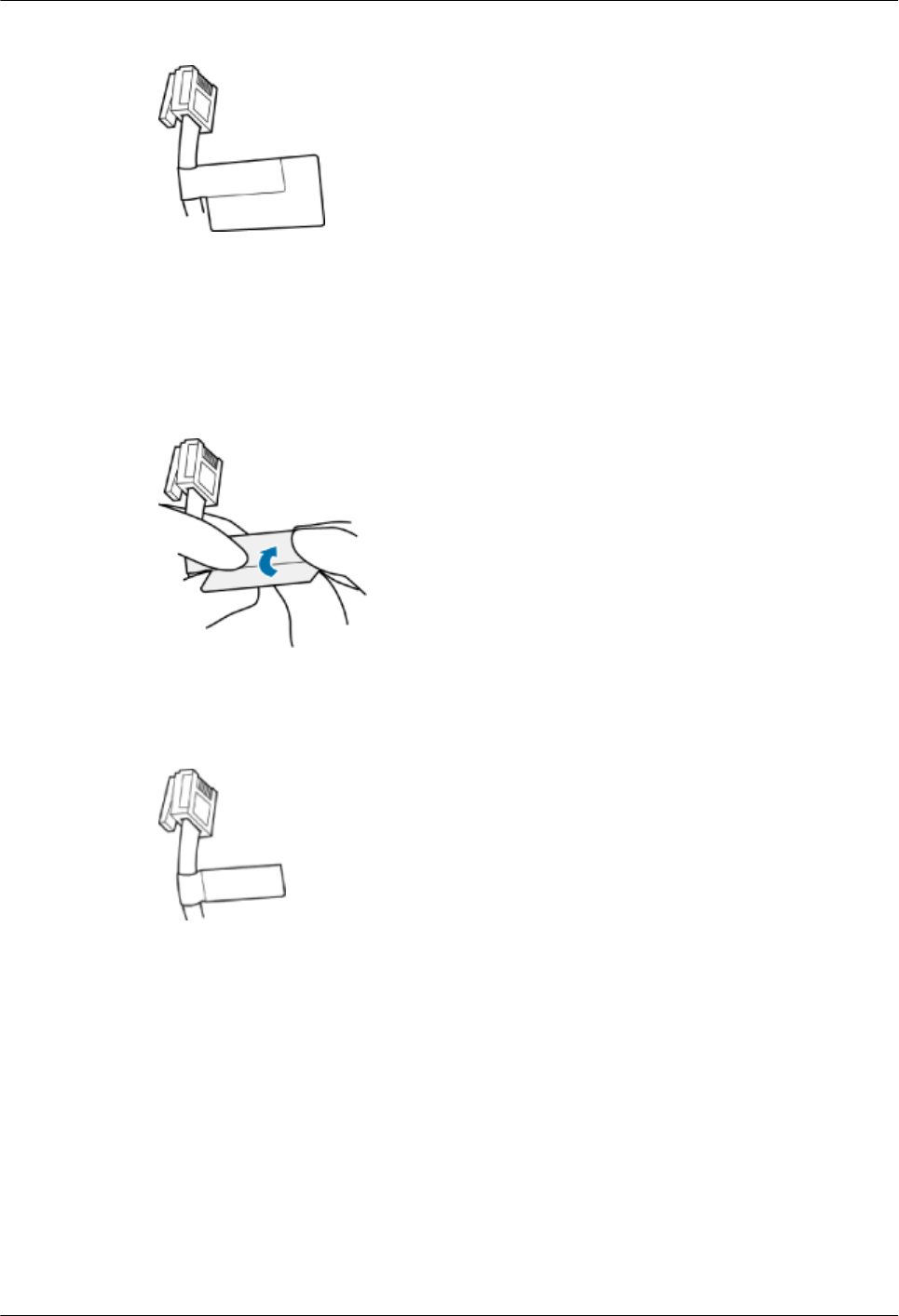
Figure 14-9 Adhering the long end to the labeling area
Step 4 Turn over the labeling area along the adhesive face from the bottom, and then finish attaching
the engineering label, as shown in Figure 14-10 and Figure 14-11. Ensure that the edges of
the turned-over labeling area are in a line.
Figure 14-10 Turning over the labeling area along the adhesive face
Figure 14-11 Attached engineering label
Step 5 Fill in the attached blank label by referring to 14.3 DBS3900 LampSite Engineering Label.
----End
14.5 Attaching a Sign Plate Label
This section describes the procedures and precautions for attaching a sign plate label.
DBS3900 LampSite
Installation Guide 14 Appendix
Issue 07 (2015-12-30) Huawei Proprietary and Confidential
Copyright © Huawei Technologies Co., Ltd.
237
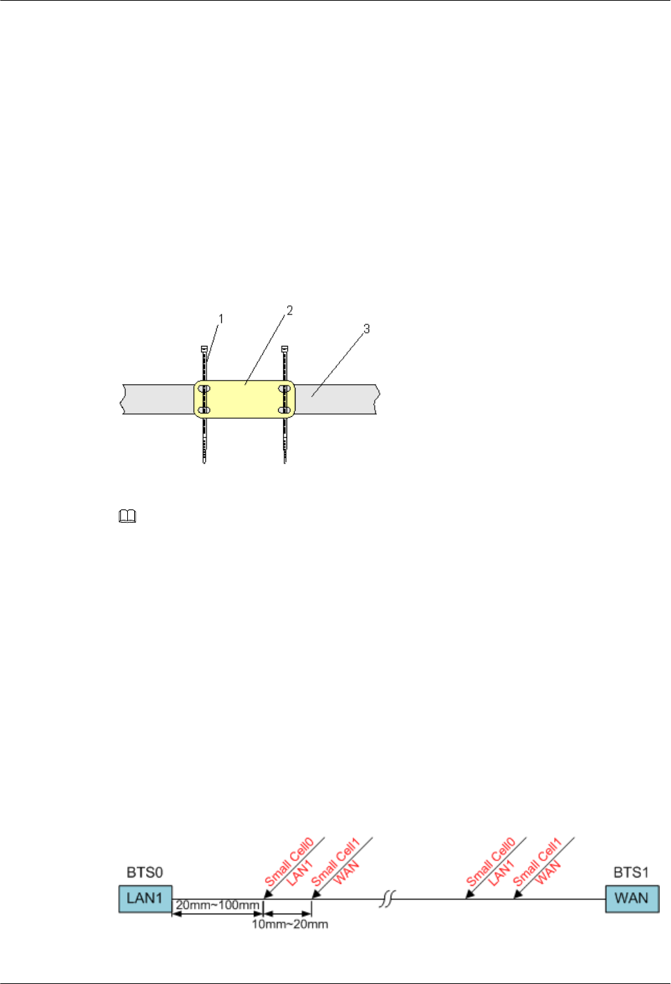
Context
lThis section applies to Huawei sign plate labels. If other engineering labels in
accordance with local standards are used on site, follow the local standards for attaching
sign plate labels.
lA sign plate label is usually used for a power cable, ground label, signal cable, and
antenna. This section uses 14.3 DBS3900 LampSite Engineering Label as an example.
Procedure
Step 1 Lead the cable ties through the holes of a label, and then bind the label to the cable, as shown
in Figure 14-12. Ensure that the cable ties are led through the holes of the label in the same
direction.
Figure 14-12 Binding the label
(1): Cable tie (2): Label (3): Cable
NOTE
You should use an outdoor cable tie with a appropriate width in outdoor scenarios (the default is black cable
tie with 3.6 mm or 0.14 in. width).
lThe position for banding the label is recommended from 20 mm to 100 mm (0.79 in. to
3.94 in.) away from the cable connector. Ensure the front of the label facing you and not
be covered.
lIn case of both ports of the cable connected have different silkscreen, both ends of the
cable should bind the port label on the two ends of cable. For example, in dual BTSs
cascading scenarios, one end of the cascading FE/GE cable is connected to LAN1 port
on BTS0, and the other end connected to WAN port on BTS1. At this point, both ends of
the cable should band two labels Micro BTS0 LAN1 and Micro BTS1 WAN. As shown
in Figure 14-13, the distance between the two labels is recommended from 10 mm to 20
mm (0.39 in. to 0.79 in.).
Figure 14-13 Positions for banding labels
DBS3900 LampSite
Installation Guide 14 Appendix
Issue 07 (2015-12-30) Huawei Proprietary and Confidential
Copyright © Huawei Technologies Co., Ltd.
238
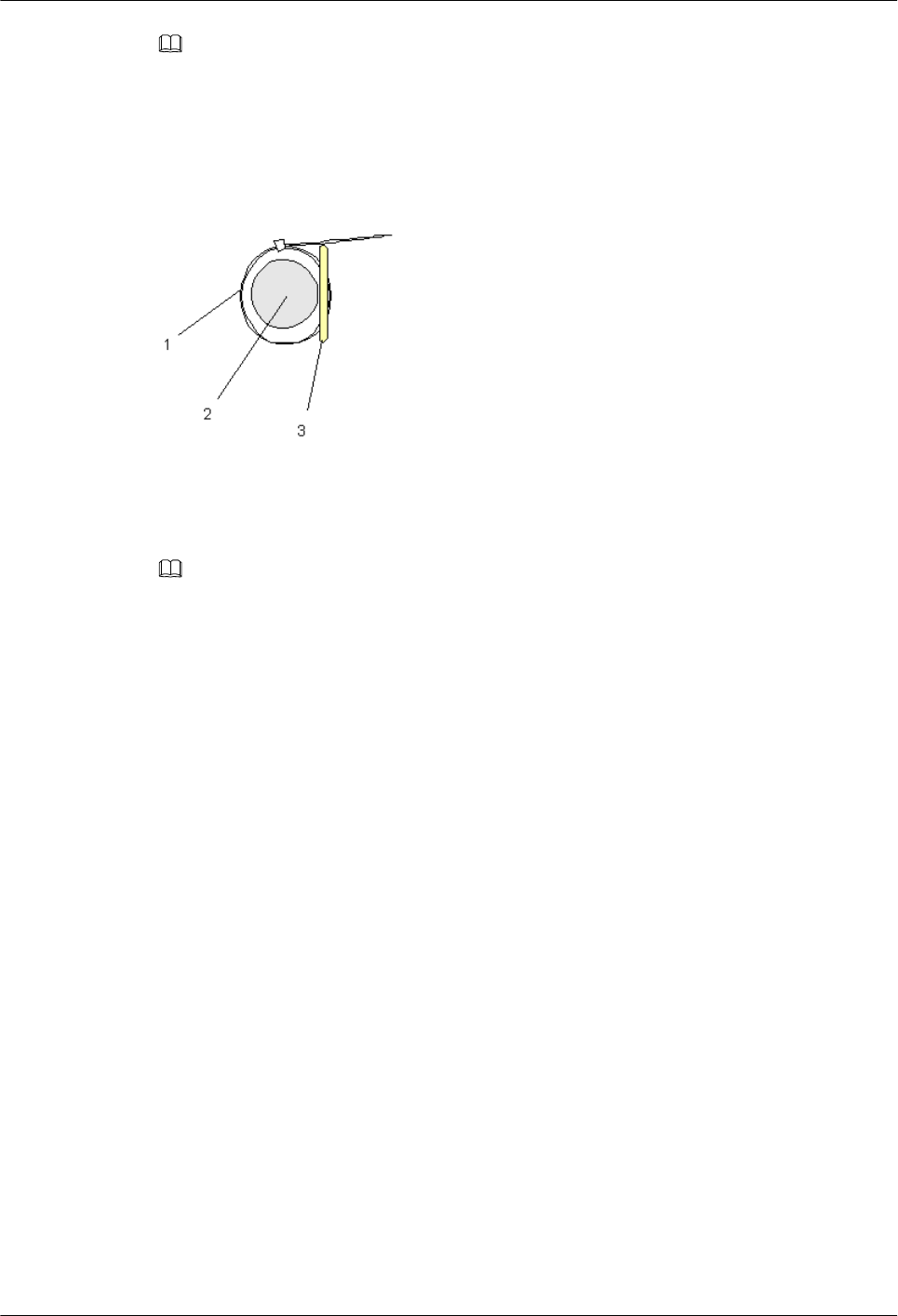
NOTE
You may change the positions for attaching labels in actual situations. For example, you can bind a label
where the cable is bent.
Step 2 Tighten the cable tie, securing the label on the cable, and then cut off the extra part of the
cable tie, as shown in Figure 14-14.
Figure 14-14 Securing the label on the cable
(1): Cable tie (2): Cable (3): Label
NOTE
lWhen you bind a label, ensure that the side with characters faces outwards.
lEnsure that the labels are attached in an orderly and neat manner. When you cut a cable tie, keep a
surplus length of 5 mm to 10 mm (0.20 in. to 0.39 in.).
----End
DBS3900 LampSite
Installation Guide 14 Appendix
Issue 07 (2015-12-30) Huawei Proprietary and Confidential
Copyright © Huawei Technologies Co., Ltd.
239

Index
DBS3900 LampSite
Installation Guide Index
Issue 07 (2015-12-30) Huawei Proprietary and Confidential
Copyright © Huawei Technologies Co., Ltd.
240

Compliance and Safety Manual Regulatory Compliance Information
Huawei
Proprietary and Confidential
Copyright © Huawei Technologies Co., Ltd. 1
1. USA Regulatory Compliance
1.1 FCC Part 15
This device complies with Part 15 of the FCC Rules. Operation is subject to the following two
conditions:
This device does not cause harmful interference.
This device must accept any interference received, including interference that may cause
undesired operation.
If this device is modified without authorization from Huawei, the device may no longer
comply with FCC requirements for Class B digital devices. In that a case, your right to use the
device may be limited by FCC regulations. Moreover, you may be required to correct any
interference to radio or television communications at your own expense.
This device has been tested and found to comply with the limits for a Class B digital device,
pursuant to Part 15 of the FCC rules. These limits are designed to provide reasonable
protection against harmful interference in a residential installation.
This device generates, uses and radiates radio frequency energy. If it is not installed and used
in accordance with the instructions, it may cause harmful interference to radio
communications.
However, there is no guarantee that interference will not occur in a particular installation. If
this device does cause harmful interference to radio or television reception, which can be
determined by turning the device off and on, the user may take one or more of the following
measures:
Reorient or relocate the receiving antenna.
Reinforce the separation between the device and receiver.
Connect the device into an outlet on a circuit different from that to which the receiver is
connected.
Consult the dealer or an experienced radio or TV technician for assistance.
pico Remote Radio Unit
1.2. Warning
This equipment complies with FCC radiation exposure limits set forth for an uncontrolled
environment .This equipment should be installed and operated with minimum distance 25cm
between the radiator& your body.
This transmitter must not be co-located or operating in conjunction with any other antenna or transmitter.

Compliance and Safety Manual Regulatory Compliance Information
Huawei
Proprietary and Confidential
Copyright © Huawei Technologies Co., Ltd. 2
2.2 RSS statement:
This device complies with Industry Canada RSS. Operation is subject to the following
two conditions: (1) this device may not cause interference, and(2) this device must accept any
interference, including interference that may cause undesired operation of the device.
Le présent appareil est conforme aux CNR d'Industrie Canada applicables aux appareils radio
RSS . L'exploitation est autoris ée aux deux conditions suivantes : (1) l'appareil ne doit pas
produire de brouillage, et (2) l'utilisateur de l'appareil doit accepter tout brouillage radioé
lectrique subi, même si le brouillage est susceptible d'en compromettre le fonctionnement.
3. Other Markets
For relevant compliance information/documentation for
markets not mentioned above, please
contact Huawei representative.
pico Remote Radio Unit
2. Canada Regulatory Compliance
2.1 RSS-Gen statement
This device complies with Industry Canada licence-exempt RSS standard(s).
Operation is subject to the following two conditions: (1) this device may not cause
interference, and (2) this device must accept any interference, including interference that may
cause undesired operation of the device.
Le présent appareil est conforme aux CNR d'Industrie Canada applicables aux appareils radio
exempts de licence. L'exploitation est autorisée aux deux conditions suivantes : (1) l'appareil
ne doit pas produire de brouillage, et (2) l'utilisateur de l'appareil doit accepter tout brouillage
radioélectrique subi, même si le brouillage est susceptible d'en compromettre le
fonctionnement.
2.3. Warning
This equipment complies with IC RF radiation exposure limits set forth for an uncontrolled environment.
This transmitter must not be co-located or operating in conjunction with any other antenna or transmitter.
This equipment should be installed and operated with minimum distance 25cm between the radiator& your
body.
Cet appareil est
conforme aux limitesd'exposition de rayonnement RF IC établiespour un environnement non contrôlé.
Cetémetteur ne doit pas être co-implanté oufonctionner en conjonction avec toute autreantenne ou trans
metteur.
Cet équipement doit être installé et utiliséavec une distance minimale de 25cm entre leradiateur
& votre corps.