Huawei Technologies RRU3201-B13 Remote Radio Unit User Manual Hardware Maintenance Guide
Huawei Technologies Co.,Ltd Remote Radio Unit Hardware Maintenance Guide
Contents
- 1. UserManual_Hardware.pdf
- 2. UserManual_Installation.pdf
- 3. UserManual_SafetyInstructions.pdf
UserManual_Hardware.pdf
RRU3201
Hardware Maintenance Guide
Issue 04
Date 2011-09-15
HUAWEI TECHNOLOGIES CO., LTD.

Copyright © Huawei Technologies Co., Ltd. 2011. All rights reserved.
No part of this document may be reproduced or transmitted in any form or by any means without prior written
consent of Huawei Technologies Co., Ltd.
Trademarks and Permissions
and other Huawei trademarks are trademarks of Huawei Technologies Co., Ltd.
All other trademarks and trade names mentioned in this document are the property of their respective holders.
Notice
The purchased products, services and features are stipulated by the contract made between Huawei and the
customer. All or part of the products, services and features described in this document may not be within the
purchase scope or the usage scope. Unless otherwise specified in the contract, all statements, information,
and recommendations in this document are provided "AS IS" without warranties, guarantees or representations
of any kind, either express or implied.
The information in this document is subject to change without notice. Every effort has been made in the
preparation of this document to ensure accuracy of the contents, but all statements, information, and
recommendations in this document do not constitute the warranty of any kind, express or implied.
Huawei Technologies Co., Ltd.
Address: Huawei Industrial Base
Bantian, Longgang
Shenzhen 518129
People's Republic of China
Website: http://www.huawei.com
Email: support@huawei.com
Issue 04 (2011-09-15) Huawei Proprietary and Confidential
Copyright © Huawei Technologies Co., Ltd.
i
About This Document
Purpose
This document describes routine maintenance procedures for an RRU3201 (referred to as RRU
in this document), such as equipment preventive maintenance and power-on and power-off
operations. It also explains how to replace the RRU and optical modules.
Product Versions
The following table lists the product versions related to this document.
Product Name Product Version
DBS3900 V100R004 and later versions
DBS3900 LTE V100R003C00 and later versions
Intended Audience
This document is intended for:
lSystem engineers
lSite maintenance engineers
Organization
1 Changes in the RRU3201 Hardware Maintenance Guide
This chapter describes the changes in the RRU3201 Hardware Maintenance Guide.
2 Preventative Maintenance Items for an RRU
Preventative maintenance for an RRU improves the reliability of the RRU. You are advised to
perform scheduled maintenance yearly.
3 Powering On and Off an RRU
RRU3201
Hardware Maintenance Guide About This Document
Issue 04 (2011-09-15) Huawei Proprietary and Confidential
Copyright © Huawei Technologies Co., Ltd.
ii
After an RRU is powered on, check the status of RRU indicators and voltage. Before the RRU
is powered off, follow the normal power-off or emergency power-off procedure as required.
4 Replacing an RRU
A distributed base station consists of RRUs and a BBU. Replacing an RRU interrupts all the
services carried by the RRU, and alarms are generated.
5 Replacing an Optical Module
An optical module implements optical-electrical conversion, enabling optical transmission
between an RRU and other devices. You must disconnect fiber optic cables from an optical
module before replacing the optical module. Disconnecting the fiber optic cables interrupts the
transmission of CPRI signals.
Conventions
Symbol Conventions
The symbols that may be found in this document are defined as follows.
Symbol Description
Indicates a hazard with a high level of risk, which if not
avoided, will result in death or serious injury.
Indicates a hazard with a medium or low level of risk, which
if not avoided, could result in minor or moderate injury.
Indicates a potentially hazardous situation, which if not
avoided, could result in equipment damage, data loss,
performance degradation, or unexpected results.
Indicates a tip that may help you solve a problem or save
time.
Provides additional information to emphasize or supplement
important points of the main text.
General Conventions
The general conventions that may be found in this document are defined as follows.
Convention Description
Times New Roman Normal paragraphs are in Times New Roman.
Boldface Names of files, directories, folders, and users are in
boldface. For example, log in as user root.
Italic Book titles are in italics.
Courier New Examples of information displayed on the screen are in
Courier New.
RRU3201
Hardware Maintenance Guide About This Document
Issue 04 (2011-09-15) Huawei Proprietary and Confidential
Copyright © Huawei Technologies Co., Ltd.
iii
Command Conventions
The command conventions that may be found in this document are defined as follows.
Convention Description
Boldface The keywords of a command line are in boldface.
Italic Command arguments are in italics.
[ ] Items (keywords or arguments) in brackets [ ] are optional.
{ x | y | ... } Optional items are grouped in braces and separated by
vertical bars. One item is selected.
[ x | y | ... ] Optional items are grouped in brackets and separated by
vertical bars. One item is selected or no item is selected.
{ x | y | ... }*Optional items are grouped in braces and separated by
vertical bars. A minimum of one item or a maximum of all
items can be selected.
[ x | y | ... ]*Optional items are grouped in brackets and separated by
vertical bars. Several items or no item can be selected.
GUI Conventions
The GUI conventions that may be found in this document are defined as follows.
Convention Description
Boldface Buttons, menus, parameters, tabs, window, and dialog titles
are in boldface. For example, click OK.
>Multi-level menus are in boldface and separated by the ">"
signs. For example, choose File > Create > Folder.
Keyboard Operations
The keyboard operations that may be found in this document are defined as follows.
Format Description
Key Press the key. For example, press Enter and press Tab.
Key 1+Key 2 Press the keys concurrently. For example, pressing Ctrl+Alt
+A means the three keys should be pressed concurrently.
Key 1, Key 2 Press the keys in turn. For example, pressing Alt, A means
the two keys should be pressed in turn.
RRU3201
Hardware Maintenance Guide About This Document
Issue 04 (2011-09-15) Huawei Proprietary and Confidential
Copyright © Huawei Technologies Co., Ltd.
iv

Mouse Operations
The mouse operations that may be found in this document are defined as follows.
Action Description
Click Select and release the primary mouse button without moving
the pointer.
Double-click Press the primary mouse button twice continuously and
quickly without moving the pointer.
Drag Press and hold the primary mouse button and move the
pointer to a certain position.
RRU3201
Hardware Maintenance Guide About This Document
Issue 04 (2011-09-15) Huawei Proprietary and Confidential
Copyright © Huawei Technologies Co., Ltd.
v

Contents
About This Document.....................................................................................................................ii
1 Changes in the RRU3201 Hardware Maintenance Guide.....................................................1
2 Preventative Maintenance Items for an RRU...........................................................................3
3 Powering On and Off an RRU....................................................................................................5
3.1 Powering On an RRU.........................................................................................................................................6
3.2 Powering Off an RRU........................................................................................................................................6
4 Replacing an RRU.........................................................................................................................8
5 Replacing an Optical Module...................................................................................................11
RRU3201
Hardware Maintenance Guide Contents
Issue 04 (2011-09-15) Huawei Proprietary and Confidential
Copyright © Huawei Technologies Co., Ltd.
vi
1 Changes in the RRU3201 Hardware
Maintenance Guide
This chapter describes the changes in the RRU3201 Hardware Maintenance Guide.
04 (2011-09-15)
This is the fourth official release.
Compared with issue 03 (2011-04-15), this issue does not add any information.
Compared with issue 03 (2011-04-15), this issue incorporates the following change:
Topic Change Description
5 Replacing an Optical Module Optimized the description of the feature that
optical modules are hot-swappable.
Compared with issue 03 (2011-04-15), this issue does not remove any information.
03 (2011-04-15)
This is the third official release.
Compared with issue 02 (2011-03-15), this issue does not add any information.
Compared with issue 02 (2011-03-15), this issue incorporates the following change:
Topic Change Description
4 Replacing an RRU Added the commands for querying electronic
labels of boards online.
Compared with issue 02 (2011-03-15), this issue does not remove any information.
RRU3201
Hardware Maintenance Guide 1 Changes in the RRU3201 Hardware Maintenance Guide
Issue 04 (2011-09-15) Huawei Proprietary and Confidential
Copyright © Huawei Technologies Co., Ltd.
1
02 (2011-03-15)
This is the second official release.
Compared with issue 01 (2011-01-20), this issue does not add any information.
Compared with issue 01 (2011-01-20), this issue incorporates the following change:
Topic Change Description
4 Replacing an RRU Added the procedures for querying electronic
labels of boards.
Compared with issue 01 (2011-01-20), this issue does not remove any information.
01 (2011-01-20)
This is the first official release.
Compared with draft A (2010-12-15), this issue does not add any information.
Compared with draft A (2010-12-15), this issue incorporates the following change:
Topic Change Description
4 Replacing an RRU Optimized the figure of replacing an RRU.
Compared with draft A (2010-12-15), this issue does not remove any information.
Draft A (2010-12-15)
This is the draft.
Compared with issue 02 (2010-07-30) of V100R002C00, this issue does not add any information.
Compared with issue 02 (2010-07-30) of V100R002C00, this issue does not incorporate any
change.
Compared with issue 02 (2010-07-30) of V100R002C00, this issue does not remove any
information.
RRU3201
Hardware Maintenance Guide 1 Changes in the RRU3201 Hardware Maintenance Guide
Issue 04 (2011-09-15) Huawei Proprietary and Confidential
Copyright © Huawei Technologies Co., Ltd.
2
2 Preventative Maintenance Items for an RRU
Preventative maintenance for an RRU improves the reliability of the RRU. You are advised to
perform scheduled maintenance yearly.
DANGER
While working at heights, be careful not to drop any tools, equipment, or other objects. Falling
objects may cause serious injury or death. Always wear a helmet and avoid standing in the danger
area.
The items in the following checklist are not mandatory but strongly recommended. Table 2-1
lists the preventative maintenance items for an RRU.
Table 2-1 Preventative maintenance items for an RRU
SN Item
1All RRUs are properly installed and in good condition.
2 Cables are sealed properly at the entry points of the cabinet.
3 All radio frequency (RF) cables are free from wear, cuts, cracks, or other damage.
4 All RF cable connectors are sealed properly.
5 All RF cable conduits are in good condition.
6 All power cables are free from wear, cuts, cracks, or other damage.
7 All power cable connectors are in good condition.
8 All power cable conduits are in good condition.
9 All shield layers of power cables are in good condition.
10 All power cables are sealed properly.
11 All CPRI fiber optic cables are free from wear, cuts, cracks, or other damage.
12 All screws are tightened on the cover plate of the maintenance cavity.
RRU3201
Hardware Maintenance Guide 2 Preventative Maintenance Items for an RRU
Issue 04 (2011-09-15) Huawei Proprietary and Confidential
Copyright © Huawei Technologies Co., Ltd.
3

SN Item
13 All RET cables (optional) are free from wear, cuts, cracks, or other damage.
14 All RET cable (optional) connectors are sealed properly.
If any of the statements in the checklist cannot be complied with, perform the following
corrective actions:
1. Tighten all connections.
2. Report any other faults found when filling in the checklist to the supervisor, because only
technically-qualified and trained field engineers are permitted to climb towers for further
repairs.
RRU3201
Hardware Maintenance Guide 2 Preventative Maintenance Items for an RRU
Issue 04 (2011-09-15) Huawei Proprietary and Confidential
Copyright © Huawei Technologies Co., Ltd.
4

3 Powering On and Off an RRU
About This Chapter
After an RRU is powered on, check the status of RRU indicators and voltage. Before the RRU
is powered off, follow the normal power-off or emergency power-off procedure as required.
3.1 Powering On an RRU
Set the corresponding circuit breaker on the auxiliary power device for the RRU to ON, and
check the operating status of the RRU by observing the status of RRU indicators.
3.2 Powering Off an RRU
An RRU can be powered off in two ways: normal power-off and emergency power-off. You
must power off an RRU in a normal situation such as moving the equipment or anticipating a
territorial blackout. You must also power off an RRU in an emergency such as a fire, smoke, or
water immersion occurs in the equipment room.
RRU3201
Hardware Maintenance Guide 3 Powering On and Off an RRU
Issue 04 (2011-09-15) Huawei Proprietary and Confidential
Copyright © Huawei Technologies Co., Ltd.
5
3.1 Powering On an RRU
Set the corresponding circuit breaker on the auxiliary power device for the RRU to ON, and
check the operating status of the RRU by observing the status of RRU indicators.
Prerequisite
lThe RRU hardware is installed and RRU cable connections are secure.
lThe input voltage of the RRU ranges from -36 V DC to -57 V DC.
Context
CAUTION
After you unpack an RRU, you must power on it within 24 hours. If you power off the RRU for
maintenance, you must restore power to the RRU within 24 hours.
Procedure
Step 1 Set the corresponding circuit breaker on the auxiliary power device for the RRU to ON to power
on the RRU.
DANGER
Do not look into the optical module without eye protection after the RRU is powered on.
Step 2 Keep the RRU running for three to five minutes to check the status of RRU indicators. For
details, see RRU Indicators.
Step 3 Take corresponding actions based on the status of the indicators.
If... Then...
The RRU is working properly End the power-on check task.
The RRU is faulty Set the circuit breaker to OFF. Rectify the
fault, and then go to Step 1.
----End
3.2 Powering Off an RRU
An RRU can be powered off in two ways: normal power-off and emergency power-off. You
must power off an RRU in a normal situation such as moving the equipment or anticipating a
RRU3201
Hardware Maintenance Guide 3 Powering On and Off an RRU
Issue 04 (2011-09-15) Huawei Proprietary and Confidential
Copyright © Huawei Technologies Co., Ltd.
6

territorial blackout. You must also power off an RRU in an emergency such as a fire, smoke, or
water immersion occurs in the equipment room.
Procedure
lNormal power-off
1. Set the corresponding circuit breaker on the auxiliary power device for the RRU to
OFF.
lEmergency power-off
CAUTION
Emergency power-off may damage the RRU. Therefore, this type of power-off is not
recommended in normal cases.
1. Shut off the external input power of the auxiliary power device for the RRU.
2. If time permits, set the corresponding circuit breaker on the auxiliary power device
for the RRU to OFF.
----End
RRU3201
Hardware Maintenance Guide 3 Powering On and Off an RRU
Issue 04 (2011-09-15) Huawei Proprietary and Confidential
Copyright © Huawei Technologies Co., Ltd.
7

4 Replacing an RRU
A distributed base station consists of RRUs and a BBU. Replacing an RRU interrupts all the
services carried by the RRU, and alarms are generated.
Prerequisite
lThe test UE communicates with the base station properly.
lThe types of faulty RRUs are confirmed as follows:
–If RRUs can be queried online, run the DSP BRDMFRINFO command on the LMT
to query the electronic labels of the RRUs.
–If RRUs cannot be queried online, the information about the RRUs can be queried offline
on the M2000. For details, see the procedure for querying inventory data in the M2000
documentation.
lTools and materials, such as ESD gloves, M4 Phillips screwdrivers, M6 Phillips
screwdrivers, waterproof tape, and PVC insulation tape, are ready.
lThe number and type of RRUs to be replaced are confirmed, and new RRUs are ready.
Procedure
Step 1 Run the BLK BRD command to block the RRU.
Step 2 Power off the RRU by referring to 3.2 Powering Off an RRU.
Step 3 Wear ESD gloves.
CAUTION
lTake proper ESD protection measures, for example, wear ESD gloves, to prevent electrostatic
damage to the boards, modules, or electronic components.
lPay attention to the high temperature while replacing an RRU without housing.
Step 4 Loosen the six screws on the cover plate of the RRU cabling cavity using an M4 Phillips
screwdriver, and then open the cover plate.
Step 5 Record all the cable connections on the panel of the module to be replaced.
RRU3201
Hardware Maintenance Guide 4 Replacing an RRU
Issue 04 (2011-09-15) Huawei Proprietary and Confidential
Copyright © Huawei Technologies Co., Ltd.
8
Step 6 Disconnect cables from the cabling cavity and bottom panel.
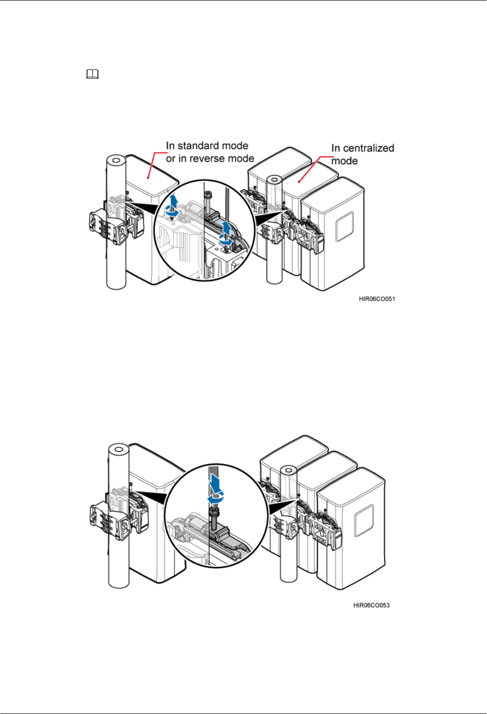
Step 7 Loosen the captive screws on the two hoist clamps on the main mounting bracket using an M4
Phillips screwdriver, as shown in Figure 4-1.
NOTE
In scenarios where RRUs are installed in centralized mode, the RRU in the middle can be removed without
removing the two RRUs on its right and left sides, in the same procedure as that for removing a single RRU.
Figure 4-1 Loosening captive screws on the main mounting bracket
Step 8 Tighten the screws on the attachment plate of the RRU using an M6 Phillips screwdriver, as
shown in Figure 4-2. Use the screw only for removing the RRU to loosen the connection between
the attachment plate and the main mounting bracket, and then support the RRU bottom to remove
it, as shown in Figure 4-3.
Figure 4-2 Tightening screws on the attachment plate
RRU3201
Hardware Maintenance Guide 4 Replacing an RRU
Issue 04 (2011-09-15) Huawei Proprietary and Confidential
Copyright © Huawei Technologies Co., Ltd.
9
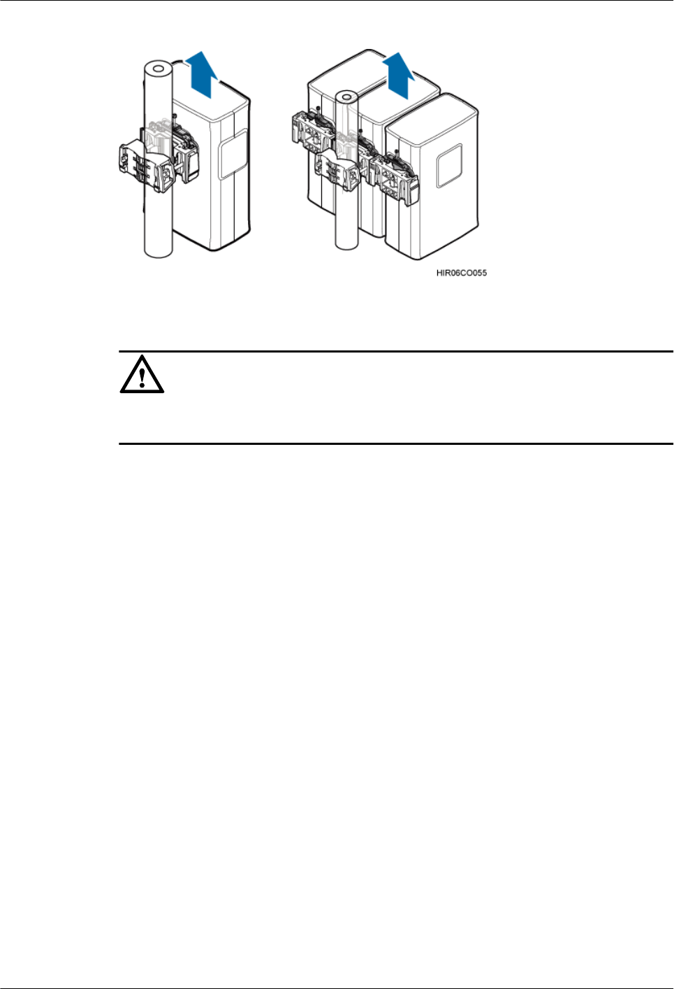
Figure 4-3 Supporting the RRU bottom
CAUTION
When removing the RRU, hold the RRU handle with one hand and support the RRU bottom
with the other hand.
Step 9 Tighten the captive screws on the two hoist clamps on the main mounting bracket to 1.4 N·m
(12.39 lbf·in.). Install a new RRU and then waterproof the RRU.
Step 10 Reconnect all required cables, and verify that vacant cable troughs in the cabling cavity are
equipped by waterproof blocks.
Step 11 Close the cover plate of the RRU cabling cavity, and then tighten the protection screw on the
cover plate to 1.4 N·m (12.39 lbf·in.).
Step 12 Power on the RRU by referring to 3.1 Powering On an RRU.
Step 13 Check the operating status of the new RRU by observing the status of RRU indicators. For details
about the status of the indicators, see RRU Indicators.
Step 14 Run the UBL BRD command to unblock the RRU.
Step 15 Take off the ESD gloves, and pack up all the tools.
----End
Follow-up Procedure
lPlace the removed RRU into the ESD box or bag. Then, place the ESD box or bag into a
foam-padded carton or the packing box of the new RRU.
lFill in the fault form with detailed information about the removed component.
lContact the local Huawei office to handle the faulty component.
RRU3201
Hardware Maintenance Guide 4 Replacing an RRU
Issue 04 (2011-09-15) Huawei Proprietary and Confidential
Copyright © Huawei Technologies Co., Ltd.
10

5 Replacing an Optical Module
An optical module implements optical-electrical conversion, enabling optical transmission
between an RRU and other devices. You must disconnect fiber optic cables from an optical
module before replacing the optical module. Disconnecting the fiber optic cables interrupts the
transmission of CPRI signals.
Prerequisite
lThe type and number of optical modules to be replaced are confirmed, and new optical
modules are ready.
lTools and materials, such as ESD gloves, M4 Phillips screwdrivers, and an ESD box or
bag, are ready.
Context
lOptical modules are inserted into CPRI_W and CPRI_E ports on an RRU.
lOptical modules are hot-swappable when the same CPRI ports are used.
lIt takes about five minutes to replace an optical module on the RRU, which involves
disconnecting fiber optic cables, removing the faulty optical module, inserting a new optical
module, reconnecting the fiber optic cables, and waiting for CPRI links to resume.
Procedure
Step 1 Wear ESD gloves.
CAUTION
Take proper ESD protection measures, for example, wear ESD gloves, to prevent electrostatic
damage to the boards, modules, or electronic components.
Step 2 Loosen the six screws on the cover plate of the RRU cabling cavity using an M4 Phillips
screwdriver, and then open the cover plate.
Step 3 Record the connections of the optical module and fiber optic cables.
Step 4 Press the latch on the fiber optic cable connector, and then remove the connector from the faulty
optical module.
RRU3201
Hardware Maintenance Guide 5 Replacing an Optical Module
Issue 04 (2011-09-15) Huawei Proprietary and Confidential
Copyright © Huawei Technologies Co., Ltd.
11

WARNING
Do not look into the fiber optic cable or optical module without eye protection after the fiber
optic cable is removed from the optical module.
Step 5 Lower the puller on the faulty optical module, and then pull the puller until the optical module
is removed from the RRU.
Step 6 Choose the optical module of the same type as the faulty optical module according to the label
on the module. Install a new optical module into the RRU.
NOTE
The optical modules to be installed must match CPRI rates.
Step 7 Insert the fiber optic cable connector into the new optical module.
Step 8 Check the transmission of CPRI signals by observing the status of CPRI_W and CPRI_E
indicators. For details about the status of the indicators, see RRU Indicators.
Step 9 Reconnect the cables in the cabling cavity.
Step 10 Close the cover plate of the RRU cabling cavity, and then tighten the protection screw on the
cover plate to 1.4 N·m (12.39 lbf·in.).
Step 11 Take off the ESD gloves, and pack up all the tools.
----End
Follow-up Procedure
lPlace the removed optical module into the ESD box or bag. Then, place the ESD box or
bag into a foam-padded carton or the packing box of the new module.
lFill in the fault form with detailed information about the removed component.
lContact the local Huawei office to handle the faulty optical module.
RRU3201
Hardware Maintenance Guide 5 Replacing an Optical Module
Issue 04 (2011-09-15) Huawei Proprietary and Confidential
Copyright © Huawei Technologies Co., Ltd.
12