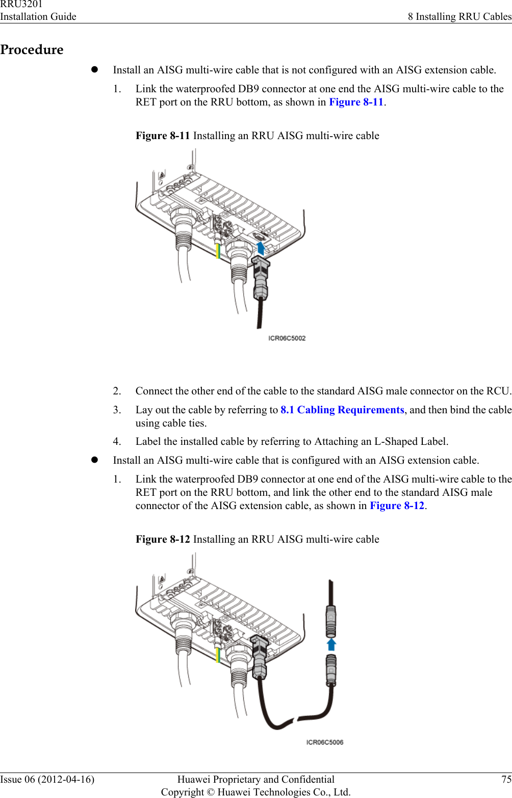
Huawei Technologies RRU3201-B13 Remote Radio Unit User Manual Installation Guide
Huawei Technologies Co.,Ltd Remote Radio Unit Installation Guide
Contents
- 1. UserManual_Hardware.pdf
- 2. UserManual_Installation.pdf
- 3. UserManual_SafetyInstructions.pdf
UserManual_Installation.pdf
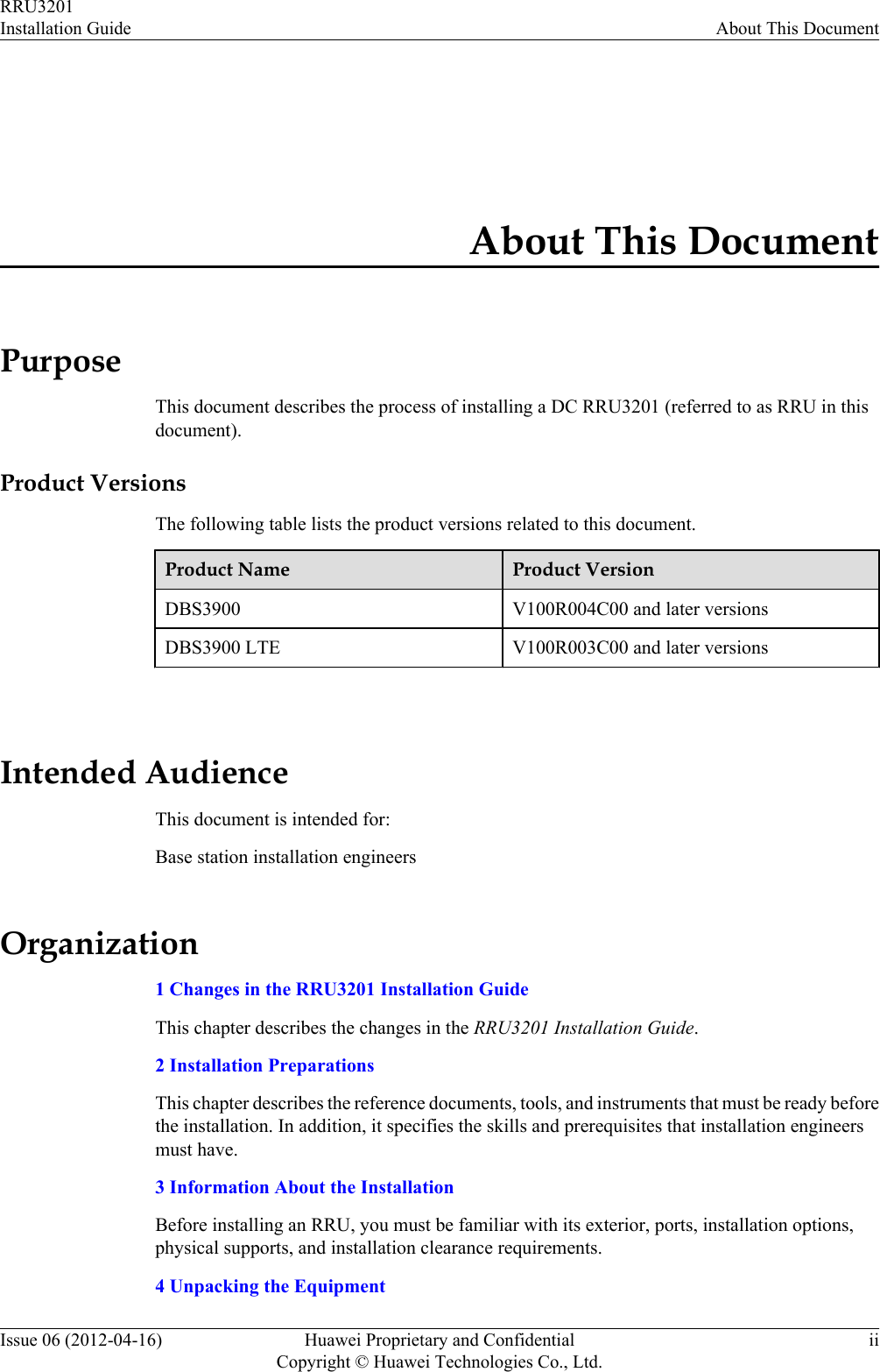
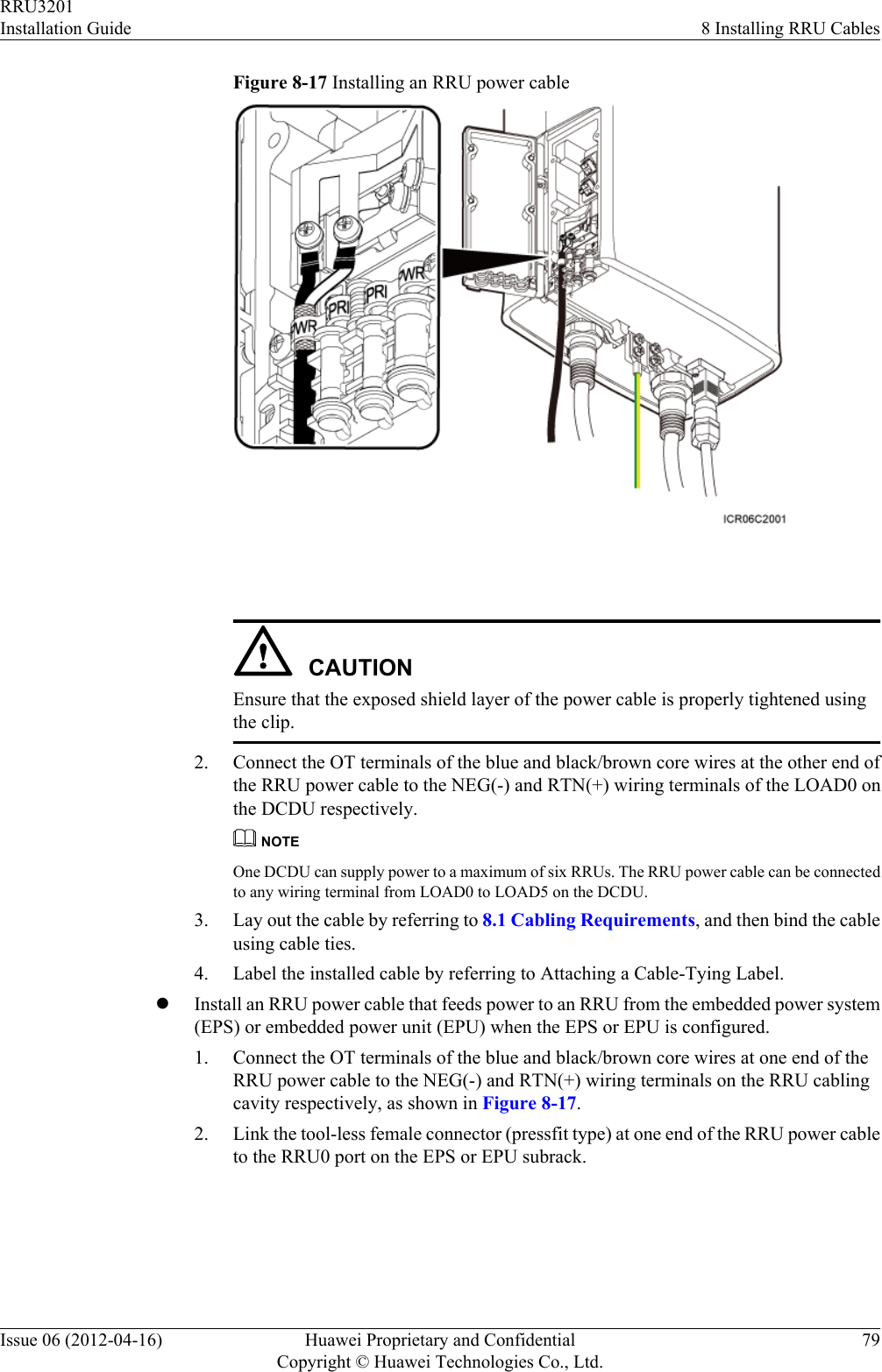
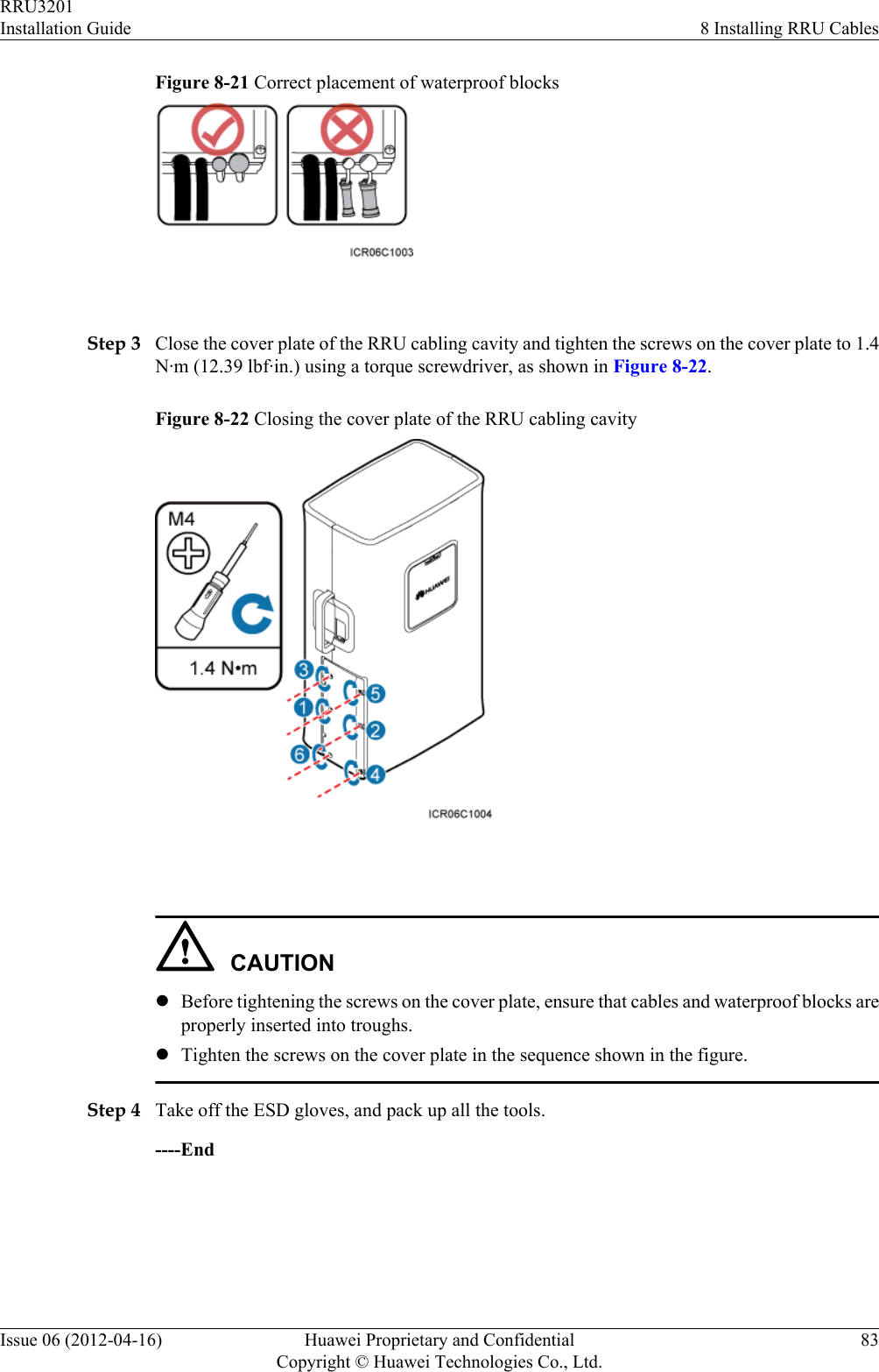
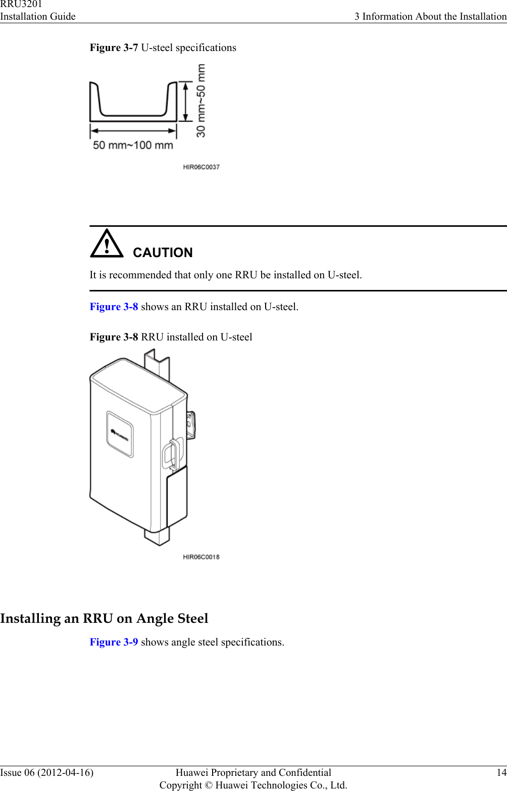
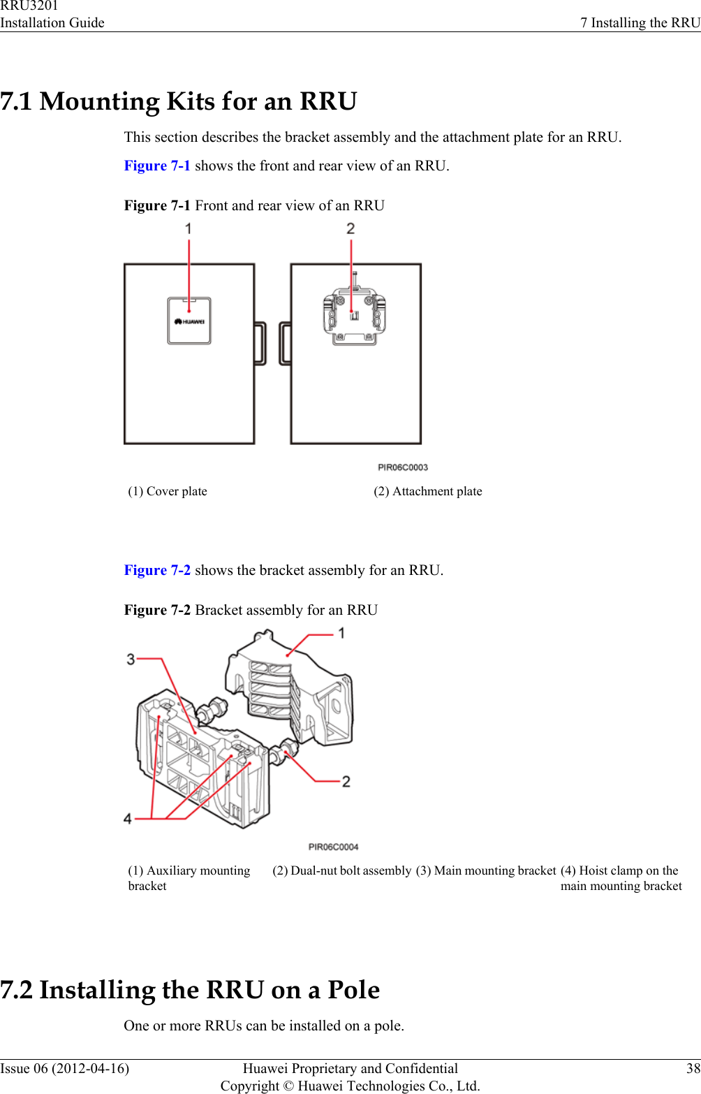
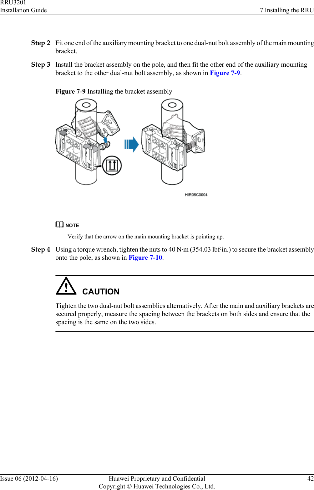
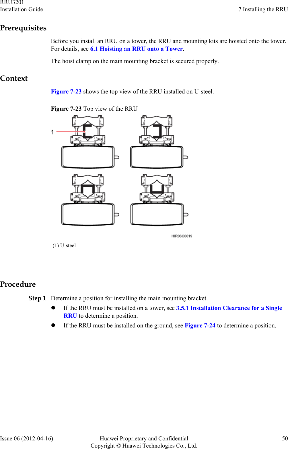
![General ConventionsThe general conventions that may be found in this document are defined as follows.Convention DescriptionTimes New Roman Normal paragraphs are in Times New Roman.Boldface Names of files, directories, folders, and users are inboldface. For example, log in as user root.Italic Book titles are in italics.Courier New Examples of information displayed on the screen are inCourier New. Command ConventionsThe command conventions that may be found in this document are defined as follows.Convention DescriptionBoldface The keywords of a command line are in boldface.Italic Command arguments are in italics.[ ] Items (keywords or arguments) in brackets [ ] are optional.{ x | y | ... } Optional items are grouped in braces and separated byvertical bars. One item is selected.[ x | y | ... ] Optional items are grouped in brackets and separated byvertical bars. One item is selected or no item is selected.{ x | y | ... }*Optional items are grouped in braces and separated byvertical bars. A minimum of one item or a maximum of allitems can be selected.[ x | y | ... ]*Optional items are grouped in brackets and separated byvertical bars. Several items or no item can be selected. GUI ConventionsThe GUI conventions that may be found in this document are defined as follows.Convention DescriptionBoldface Buttons, menus, parameters, tabs, window, and dialog titlesare in boldface. For example, click OK.RRU3201Installation Guide About This DocumentIssue 06 (2012-04-16) Huawei Proprietary and ConfidentialCopyright © Huawei Technologies Co., Ltd.iv](https://usermanual.wiki/Huawei-Technologies/RRU3201-B13.UserManual-Installation-pdf/User-Guide-2196921-Page-5.png)
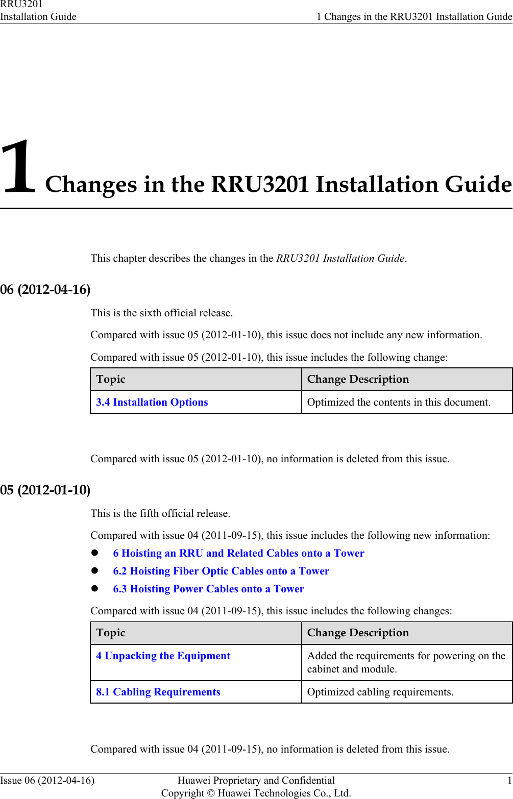
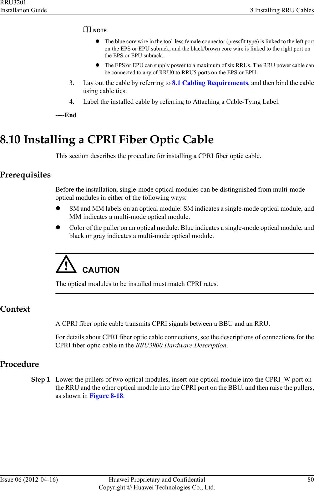
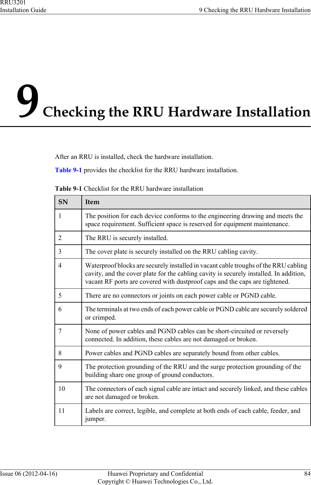
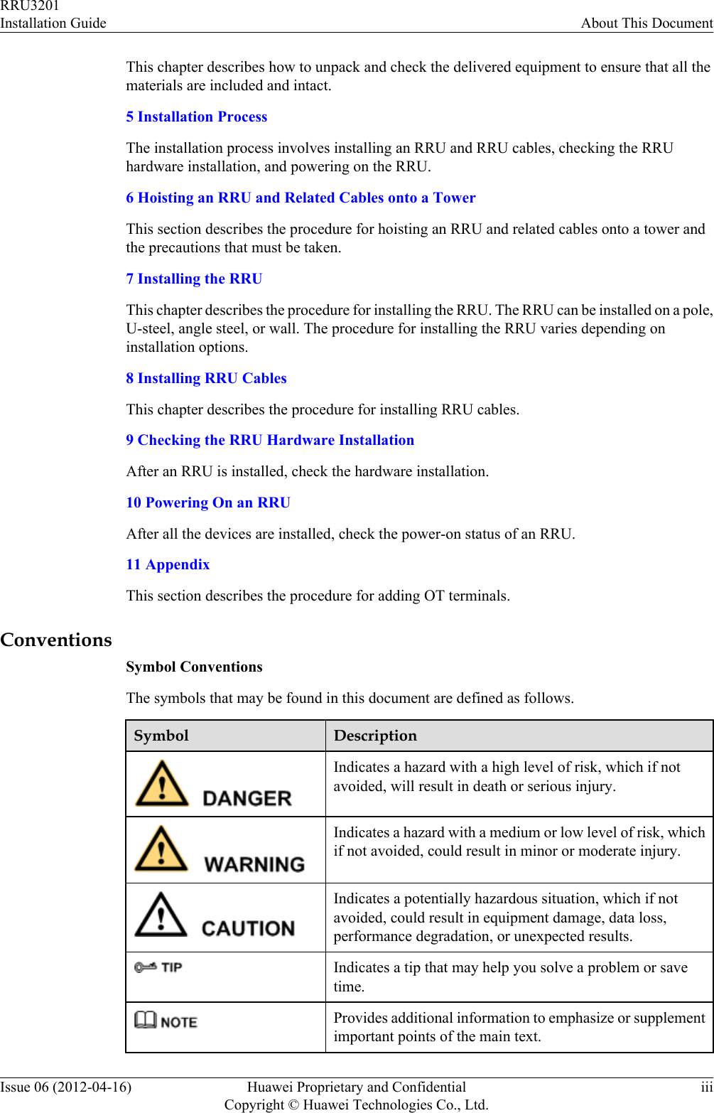
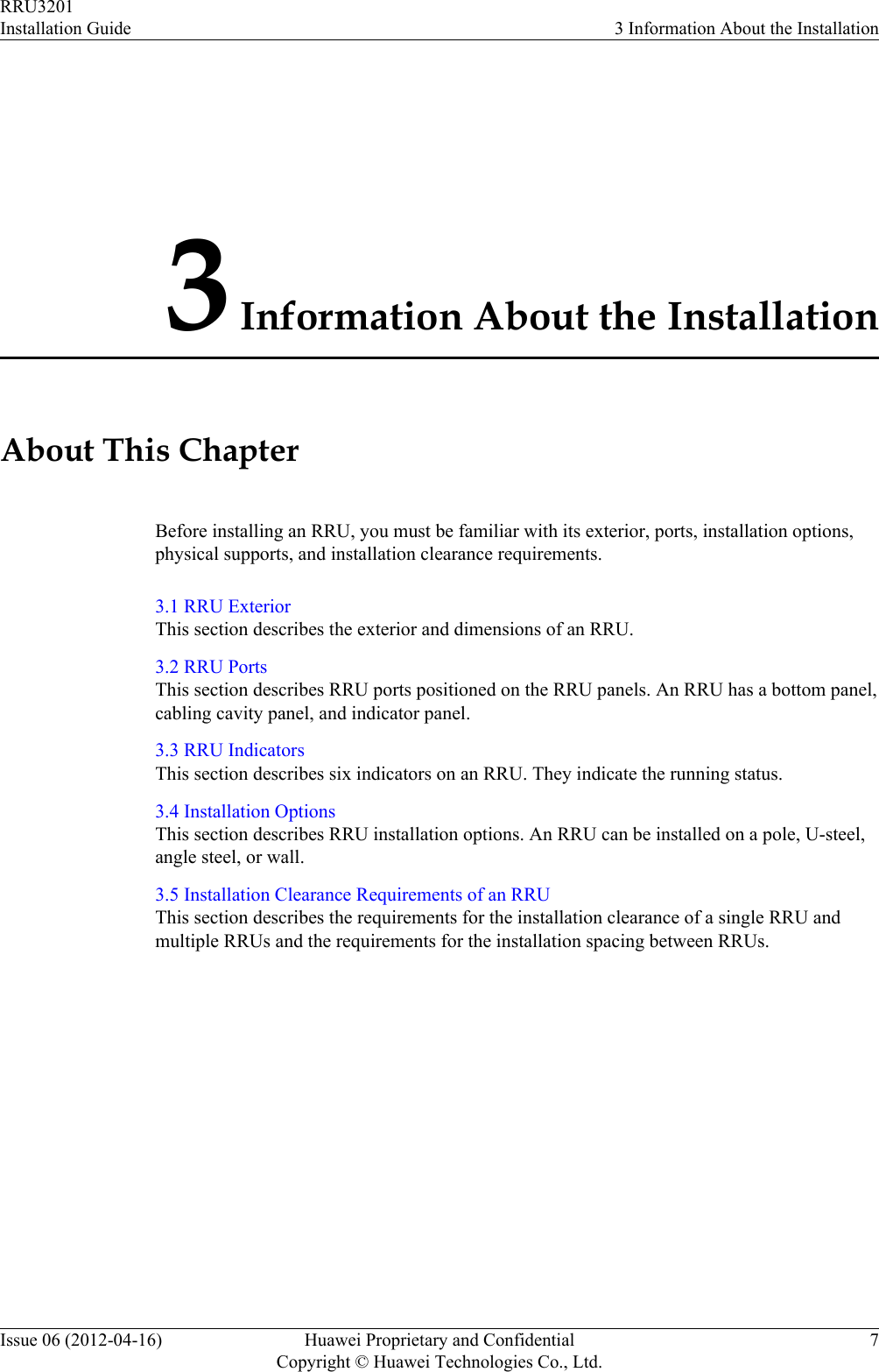
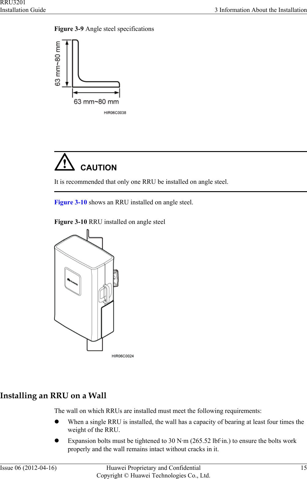
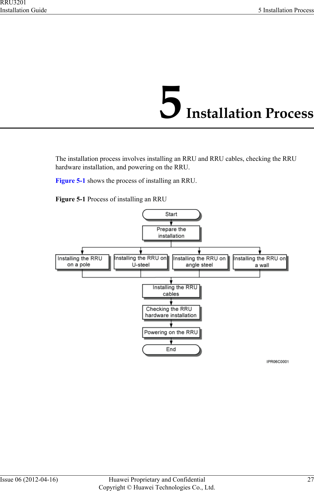
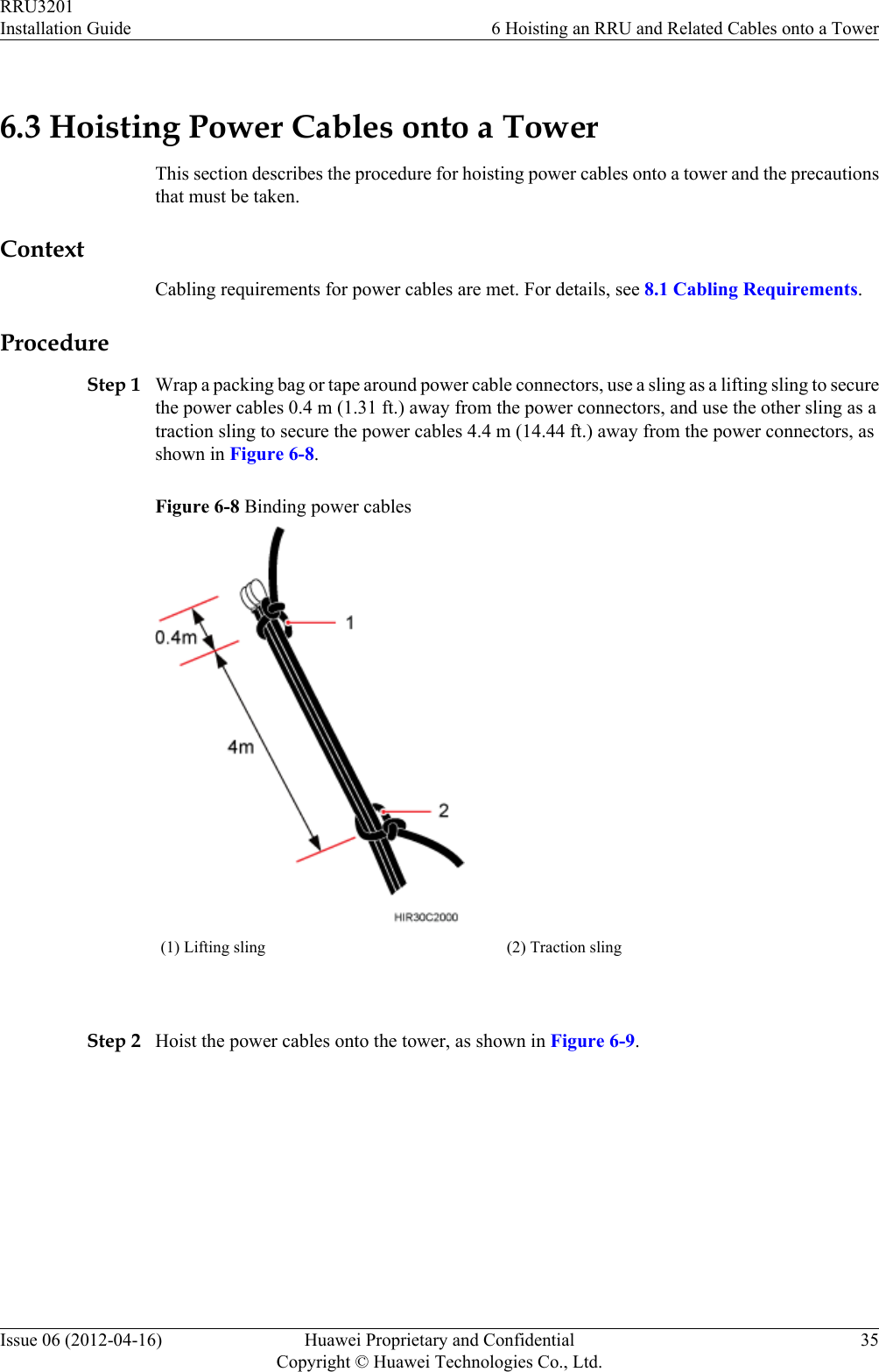
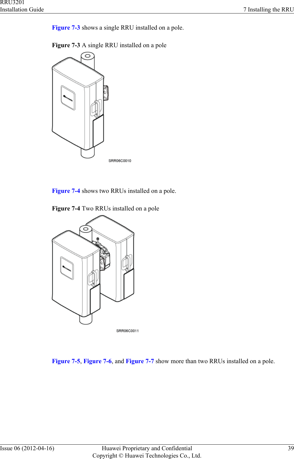
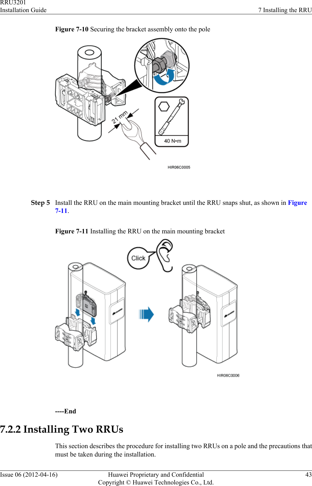
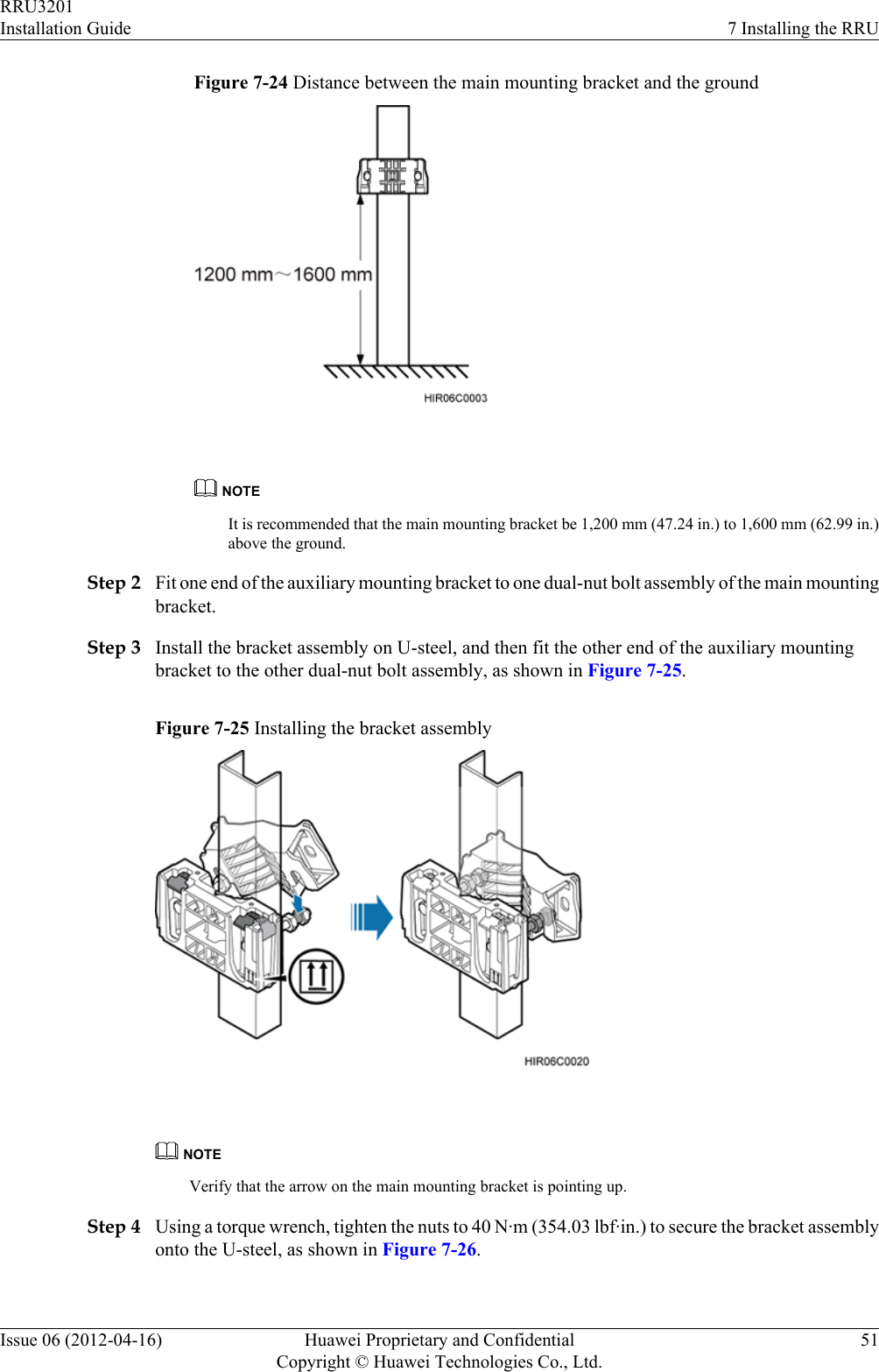
![2.1 Reference DocumentsBefore the installation, you must be familiar with reference documents.The following reference documents are required during RRU installation:lRRU3201 Hardware DescriptionlDBS3900 Installation GuidelOCB User GuideThis document describes the RRU installation on a pole, U-steel, angle steel, or wall. If RRUsare installed on the IFS06, the following reference document is required:lDBS3900 (ICR) Installation Guide2.2 Tools and InstrumentsAll tools and instruments required for RRU installation must be ready before the installation.Hammer drill (a φ 14 bit) ESD gloves Vacuum cleanerHeat gun Phillips screwdriver (M3 toM6)Flat-head screwdriver (M3 toM6)Rubber mallet COAX crimping tool Wire stripperUtility knife Cable cutter Adjustable wrench (capacity≥ 32 mm [1.26 in.])RRU3201Installation Guide 2 Installation PreparationsIssue 06 (2012-04-16) Huawei Proprietary and ConfidentialCopyright © Huawei Technologies Co., Ltd.5](https://usermanual.wiki/Huawei-Technologies/RRU3201-B13.UserManual-Installation-pdf/User-Guide-2196921-Page-13.png)
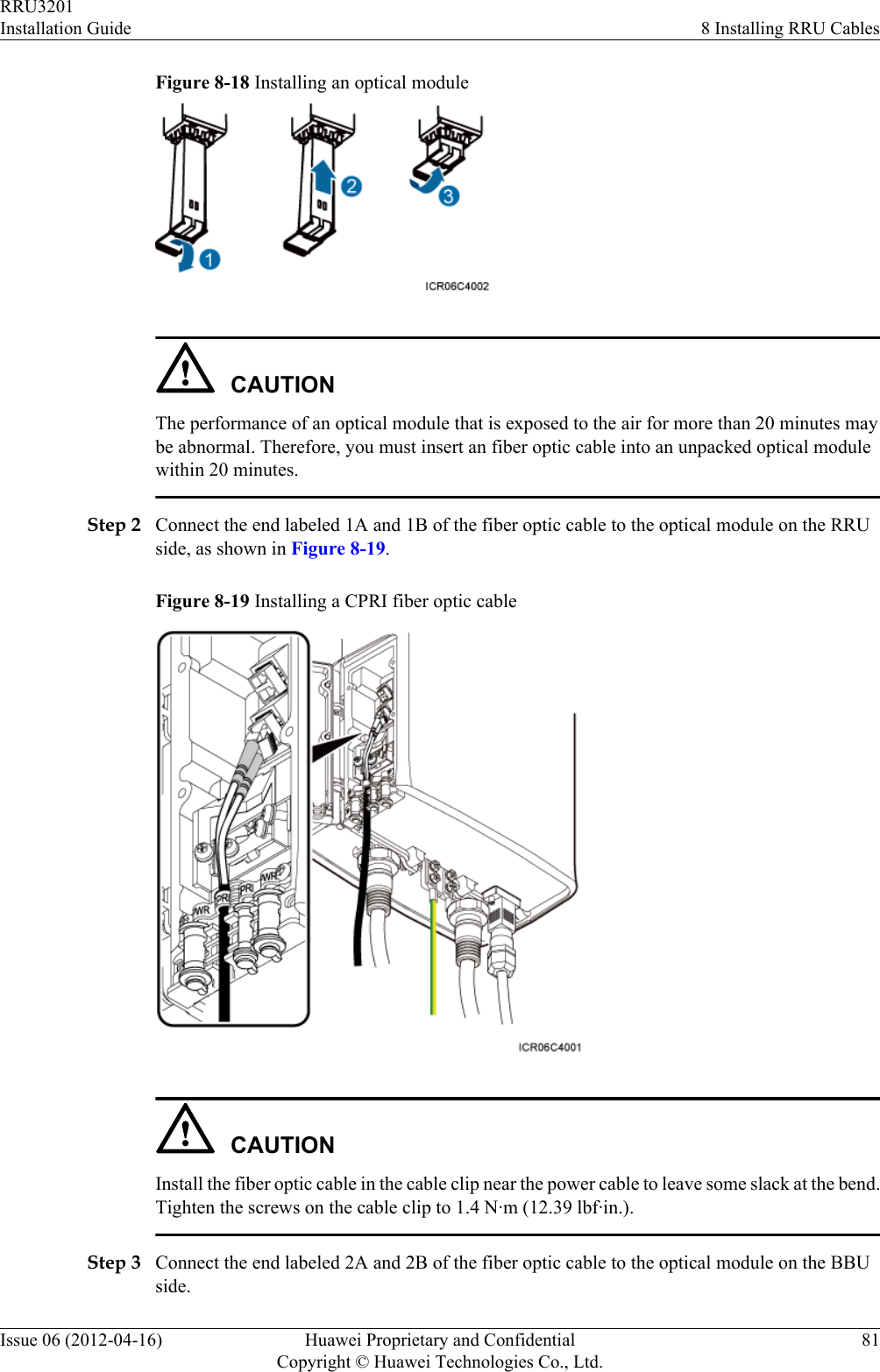
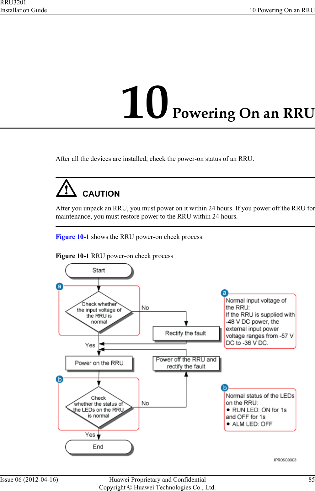
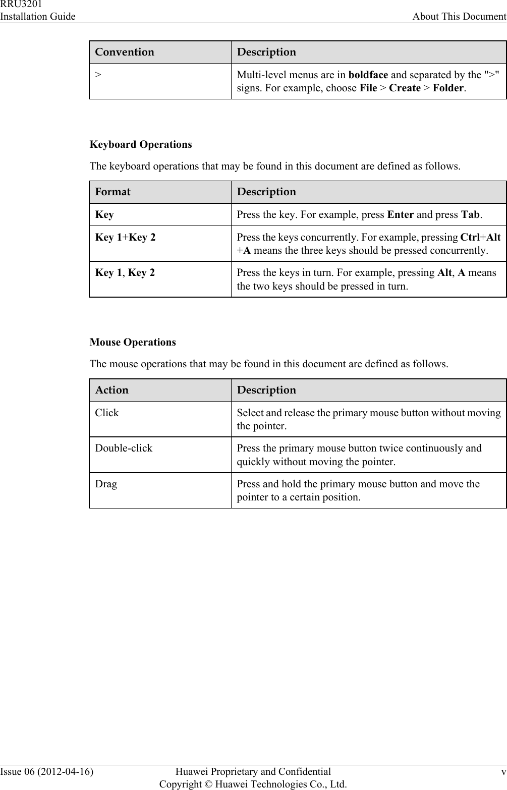
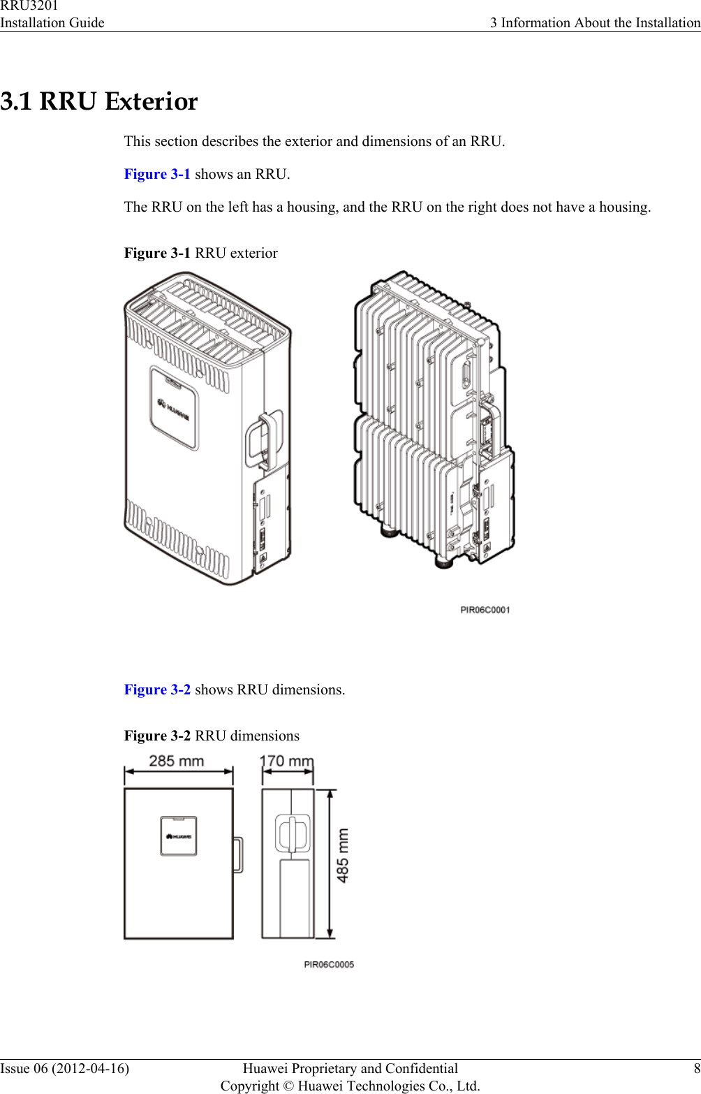
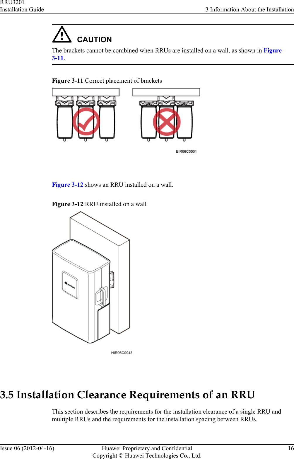
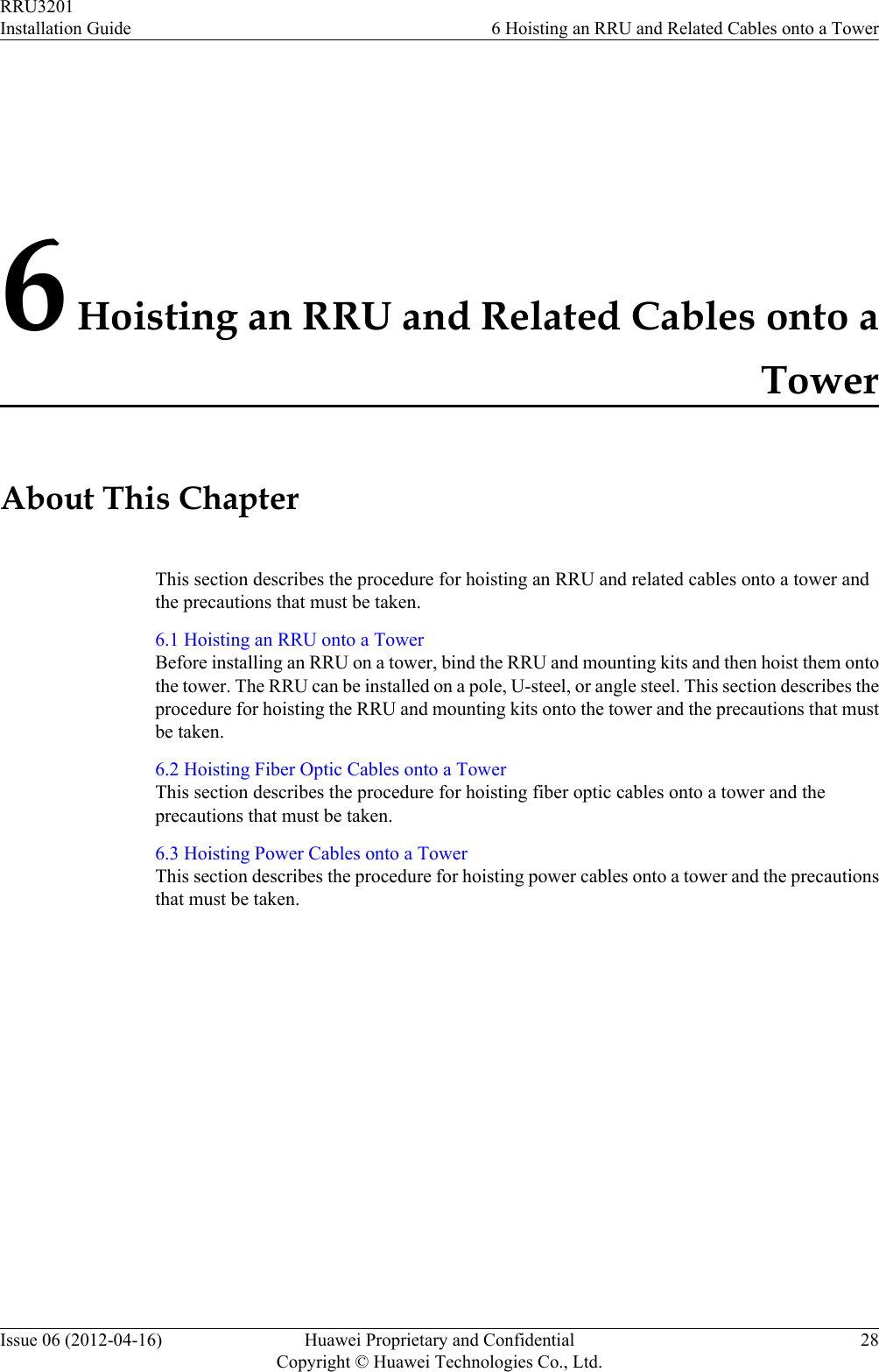
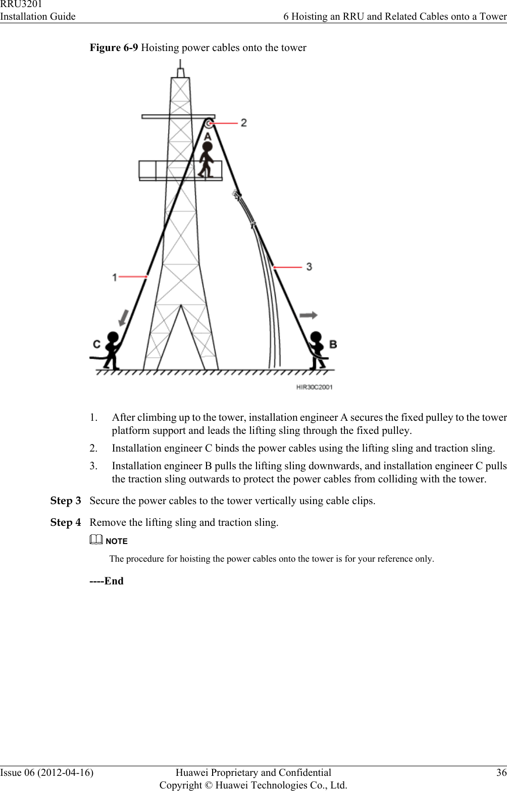
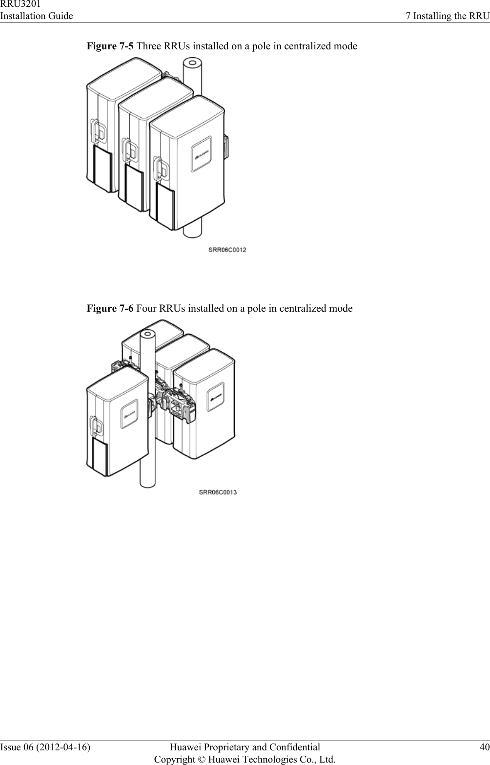
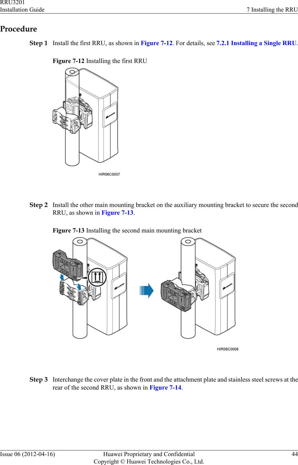
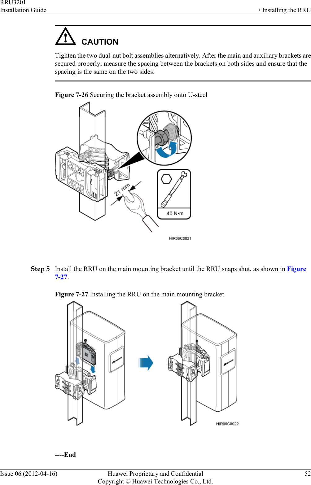
![Level Torque screwdriver5 mm(M3 to M6)(M3 to M6)Torque wrenchCapacity: 17 mm [0.67 in.], 21mm [0.82 in.], and 32 mm[1.26 in.]Combination wrenchCapacity: 17 mm [0.67 in.], 21mm [0.82 in.], and 32 mm[1.26 in.]Multimeter Marker (diameter ≤ 10 mm[0.39 in.])Measuring tape 2.3 Skills and Requirements for Onsite PersonnelOnsite personnel must be qualified and trained. Before performing any operation, onsitepersonnel must be familiar with correct operation methods and safety precautions.Before the installation, pay attention to the following items:lThe customer's technical engineers must be trained by Huawei and be familiar with theproper installation and operation methods.lThe number of onsite personnel depends on the engineering schedule and installationenvironment. Generally, only three to five onsite personnel are necessary.RRU3201Installation Guide 2 Installation PreparationsIssue 06 (2012-04-16) Huawei Proprietary and ConfidentialCopyright © Huawei Technologies Co., Ltd.6](https://usermanual.wiki/Huawei-Technologies/RRU3201-B13.UserManual-Installation-pdf/User-Guide-2196921-Page-14.png)
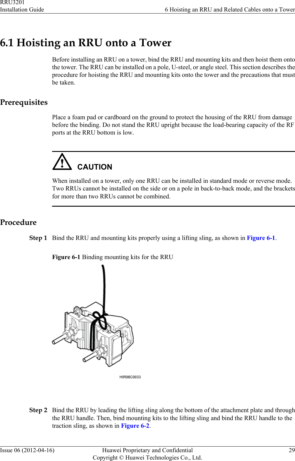
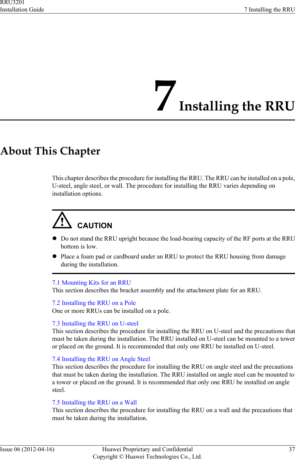
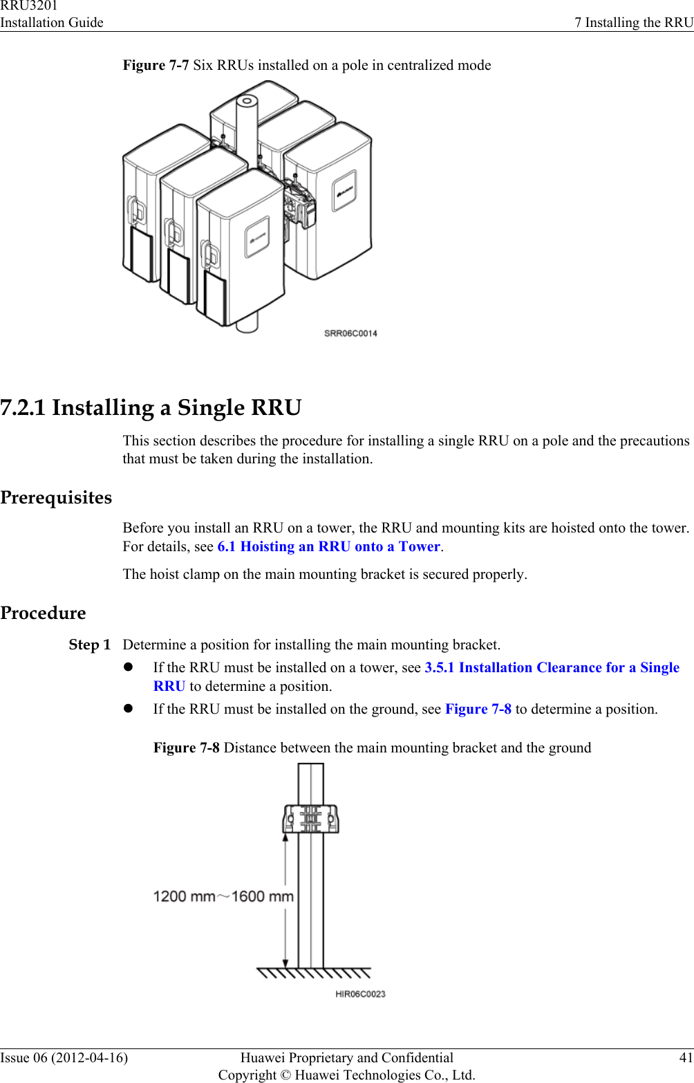
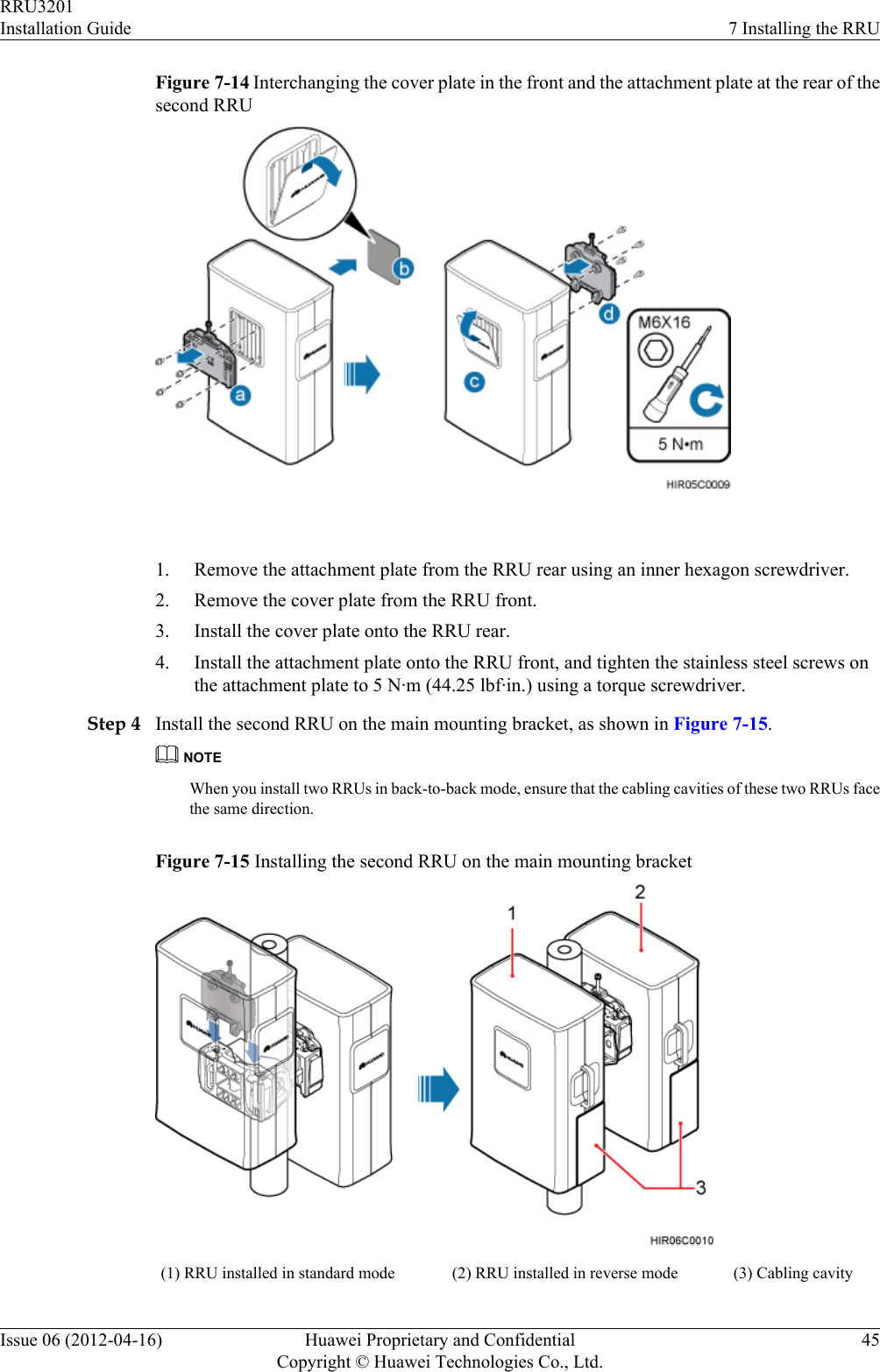
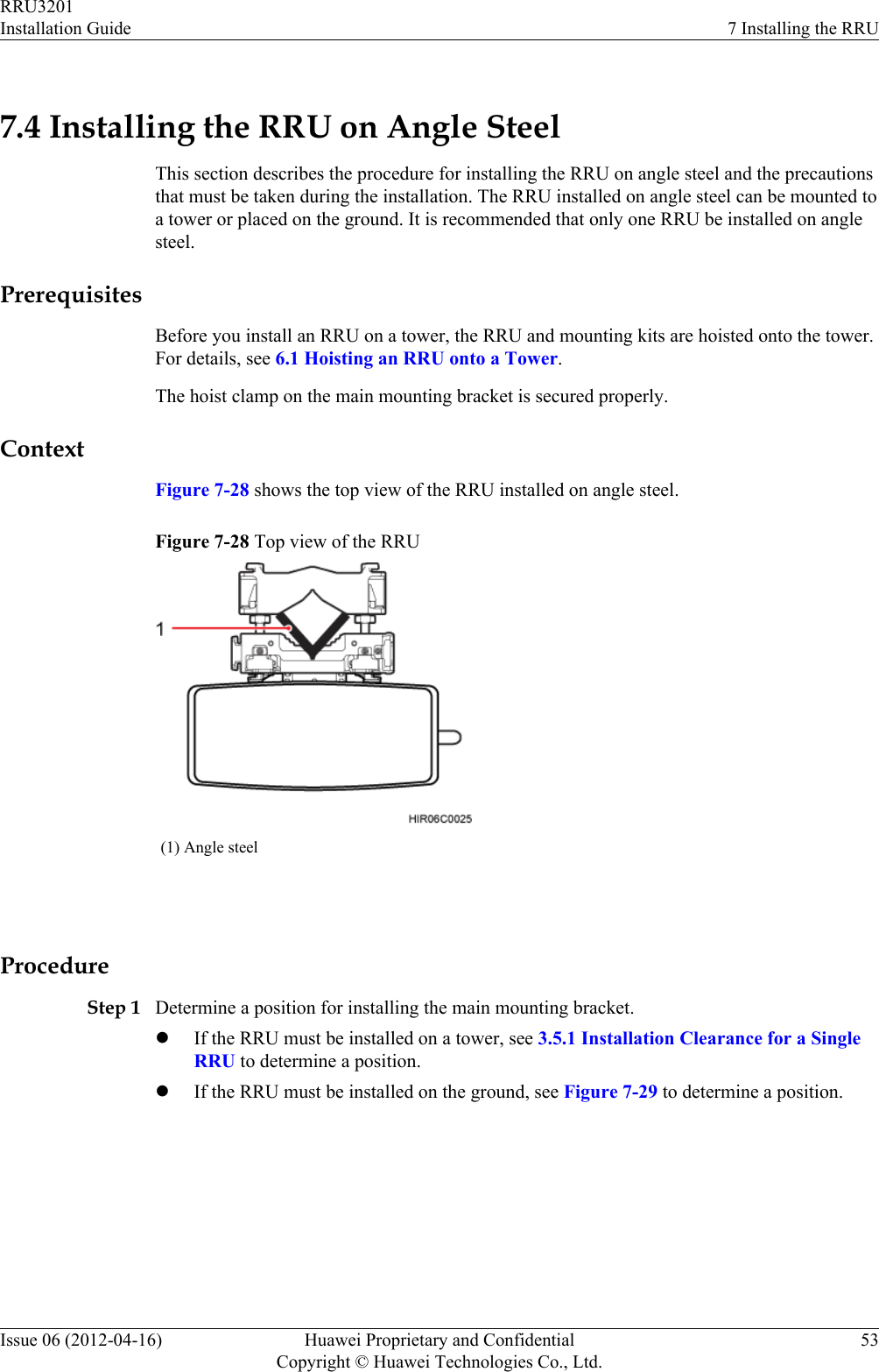
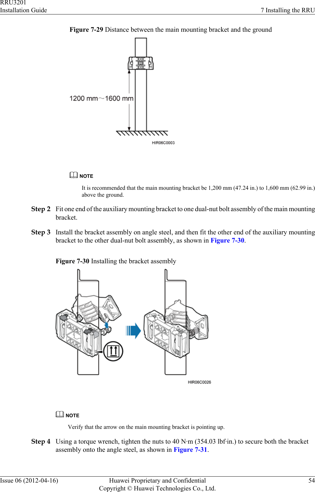
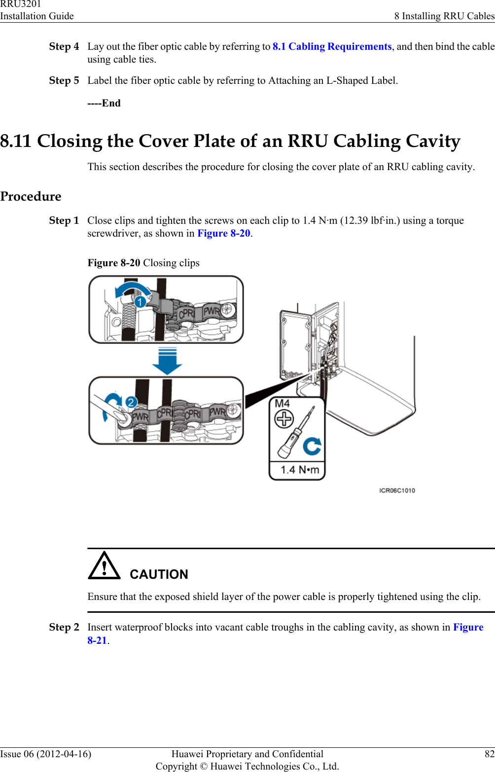
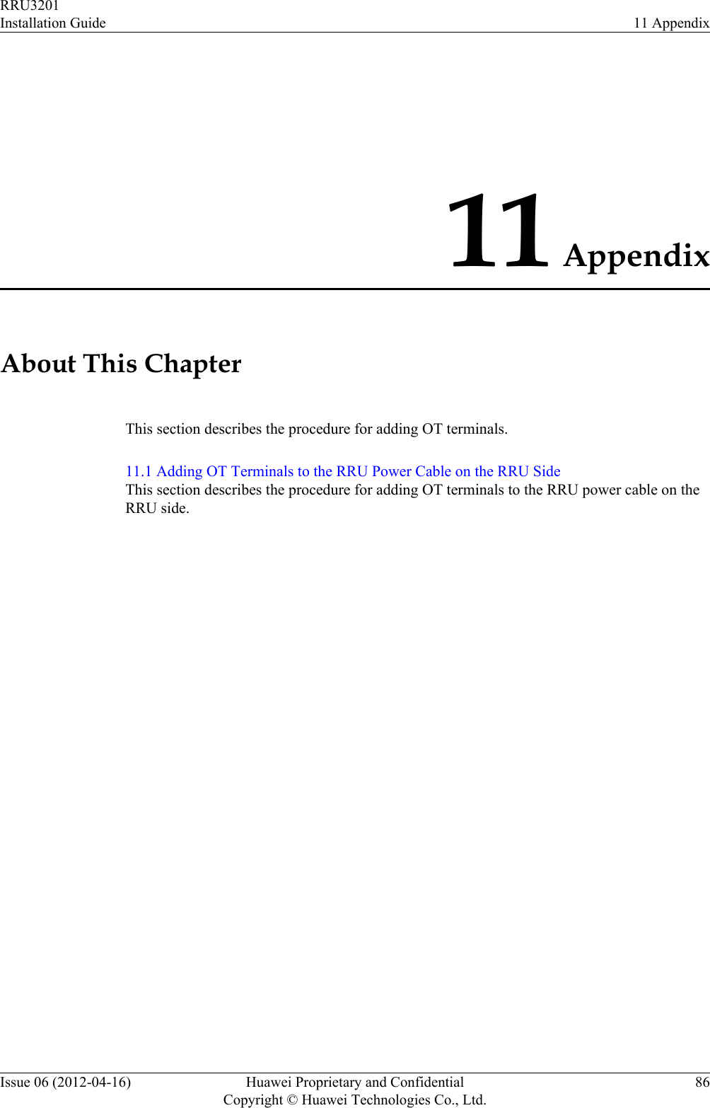
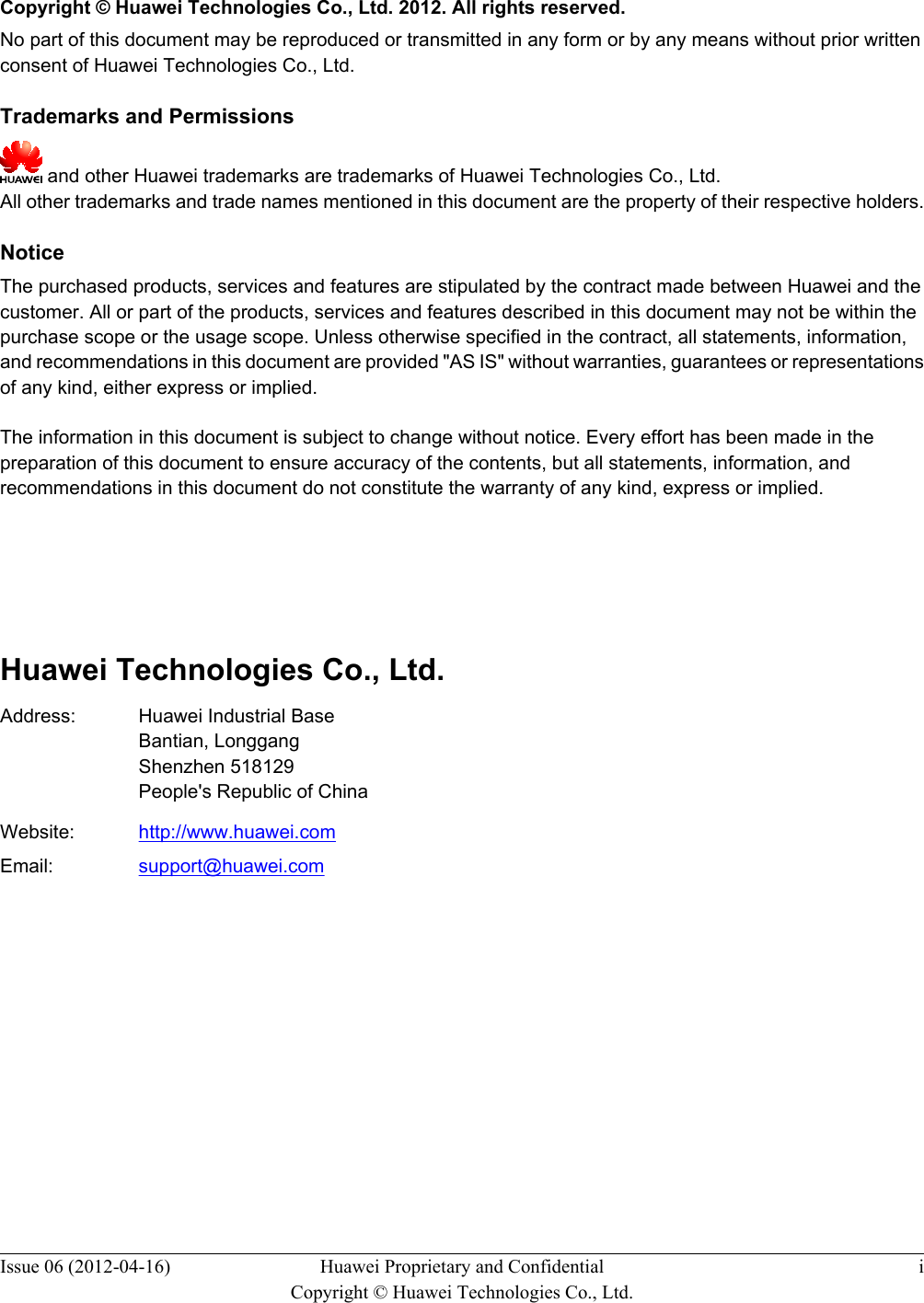
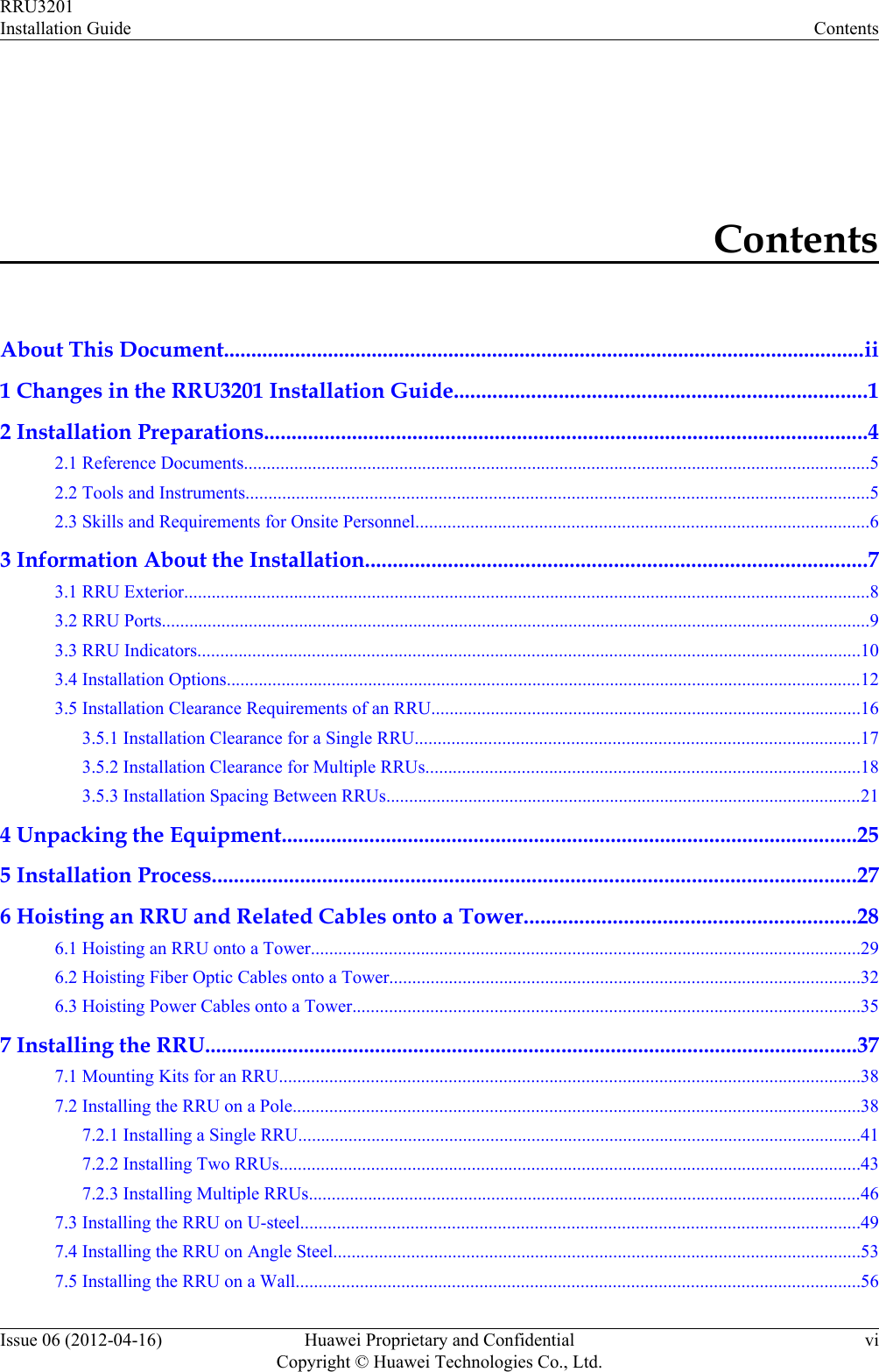
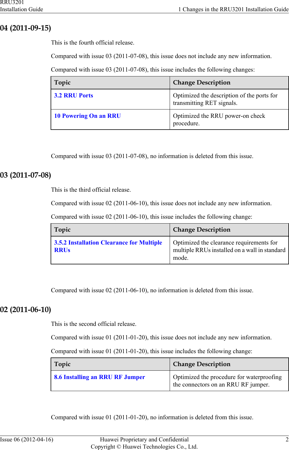
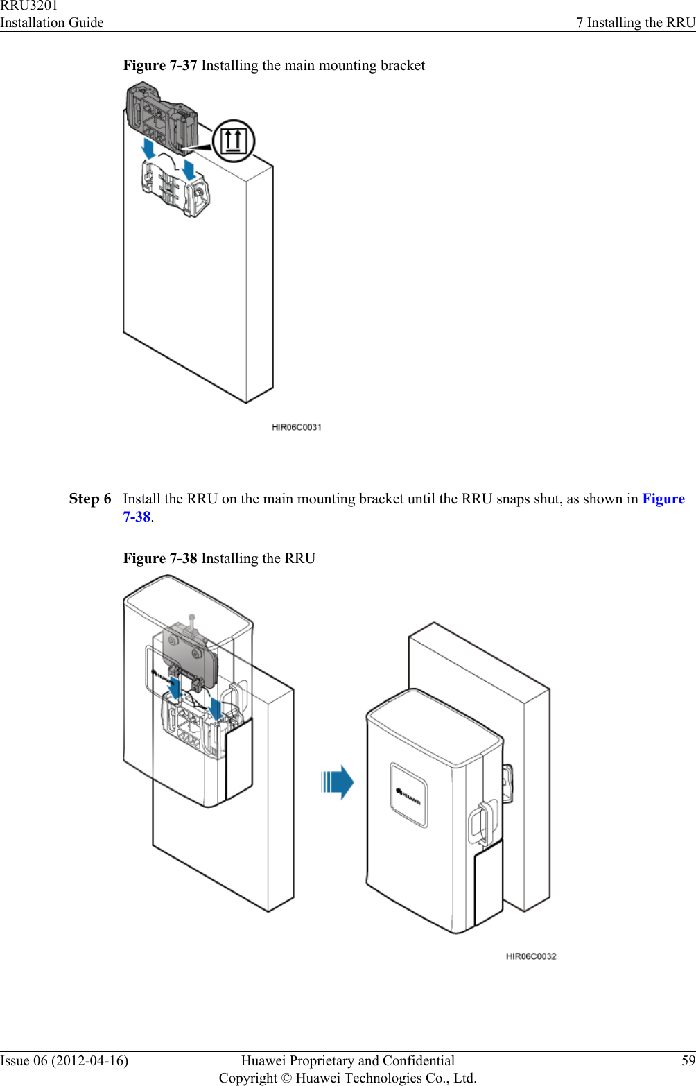
![2. Hit the expansion bolt with a rubber mallet until the expansion tube completely enters thehole.3. Tighten an expansion bolt slightly and place it vertically into each hole.4. Remove the M10x65 bolt, spring washer, plastic tube, and flat washer from each expansionbolt assembly in sequence.NOTEAfter completely removing an expansion bolt, store the plastic tube properly.5. Hammer the bolt into the wall.CAUTIONDo not hammer the expansion bolt entirely into the wall. Instead, leave 20 mm (0.79 in.)to 30 mm (1.18 in.) of the expansion bolt outside the wall.Step 3 Fit the auxiliary mounting bracket on the expansion bolt, and then use a torque wrench (17 mm[0.67 in.]) to tighten the expansion bolt to 30 N·m (265.52 lbf·in.), as shown in Figure 7-36.Figure 7-36 Fitting the auxiliary mounting bracket on expansion bolts CAUTIONVerify that the arrow on the auxiliary mounting bracket is pointing up.Step 4 Loosen the screws on the main mounting bracket and store them properly.Step 5 Install the main mounting bracket, as shown in Figure 7-37.RRU3201Installation Guide 7 Installing the RRUIssue 06 (2012-04-16) Huawei Proprietary and ConfidentialCopyright © Huawei Technologies Co., Ltd.58](https://usermanual.wiki/Huawei-Technologies/RRU3201-B13.UserManual-Installation-pdf/User-Guide-2196921-Page-66.png)

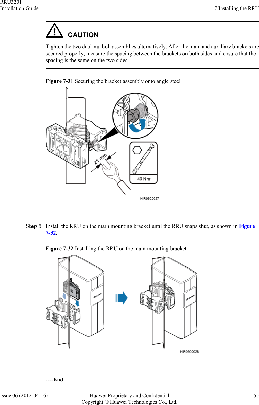
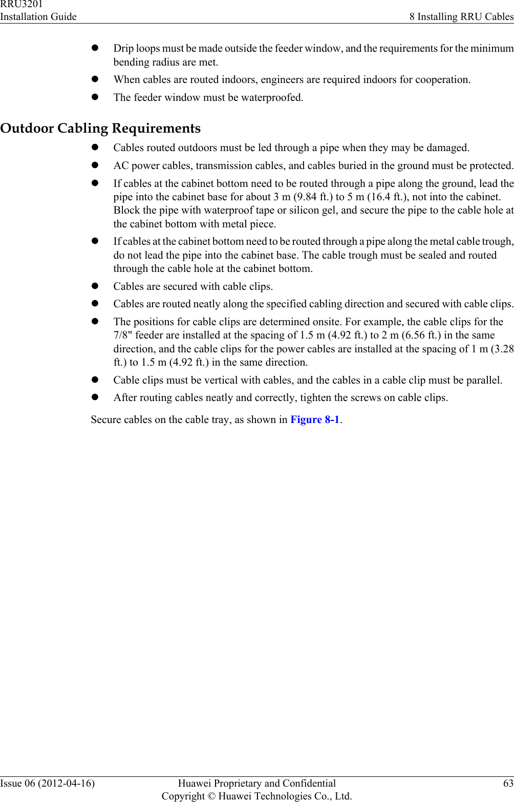
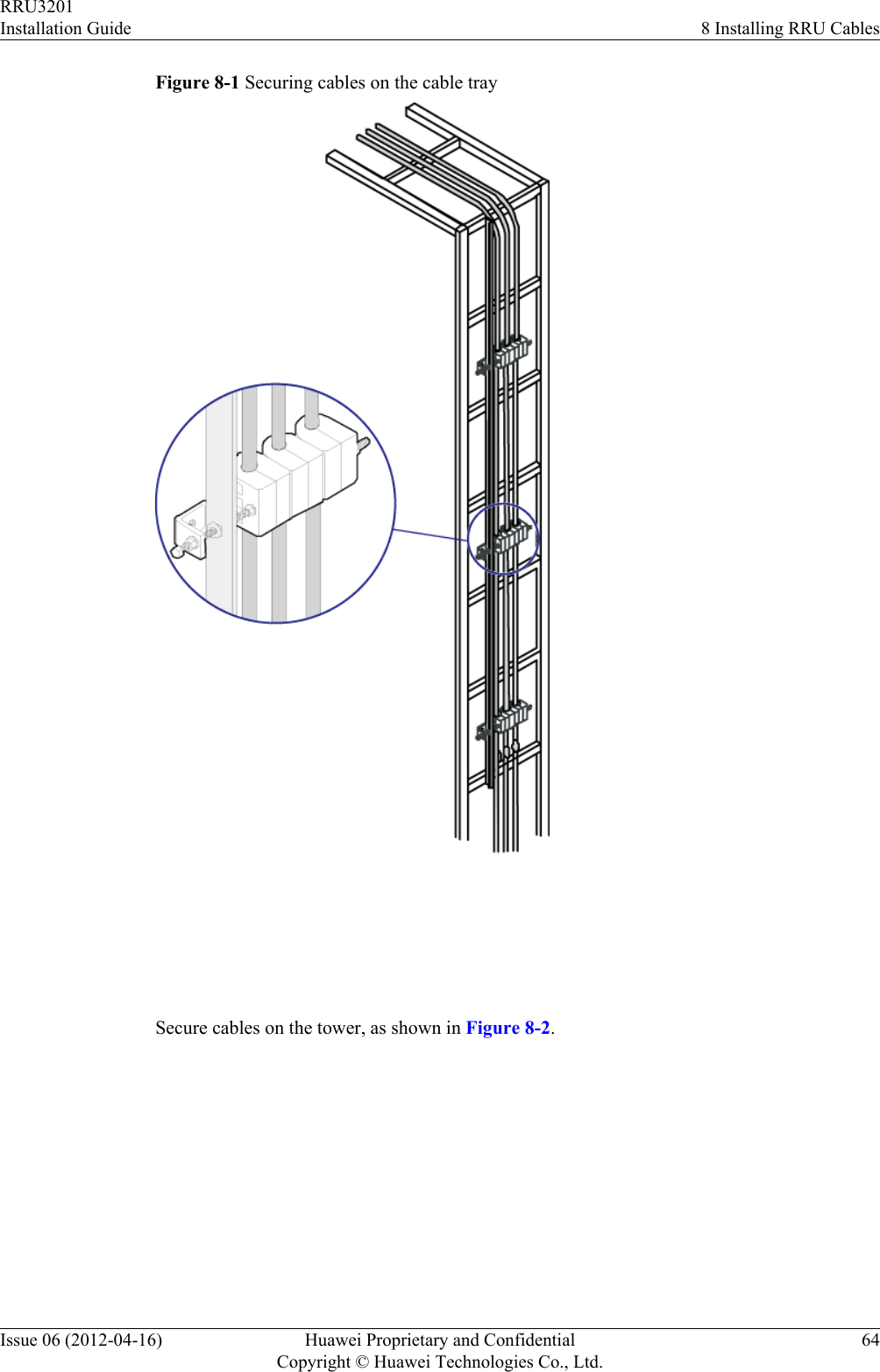
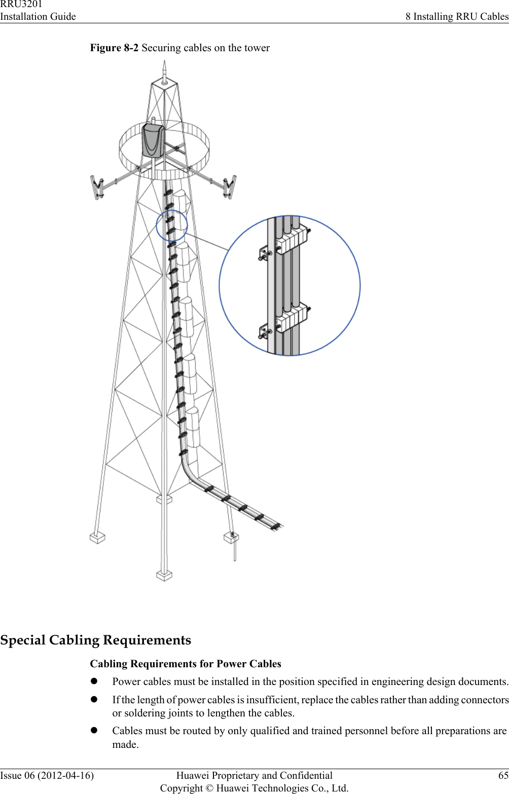
![8.1 Cabling RequirementsCables must be routed according to the specified cabling requirements to prevent signalinterference.NOTEIf a cable listed below is not required, skip the routing requirements of the cable.General Cabling RequirementsRequirements for Bending RadiuslThe bending radius of the 7/8'' feeder must be more than 250 mm (9.84 in.), and the bendingradius of the 5/4'' feeder must be more than 380 mm (14.96 in.).lThe bending radius of the 1/4'' jumper must be more than 35 mm (1.38 in.). The bendingradius of the super-flexible 1/2'' jumper must be more than 50 mm (1.97 in.), and the bendingradius of the ordinary 1/2'' jumper must be more than 127 mm (5 in.).lThe bending radius of the power cable or PGND cable must be at least three times thediameter of the cable.lThe bending radius of a fiber optic cable is at least 20 times the diameter of the fiber opticcable, and the minimum bending radius of the breakout cable at each end of the fiber opticcable is 30 mm (1.18 in.).lThe bending radius of the E1/T1 cable must be at least three times the diameter of the cable.lThe bending radius of the signal cable must be at least five times the diameter of the cable.Requirements for Cable BindinglThe same types of cable must be bound together.lDifferent types of cable must be separately routed with the minimum spacing of 30 mm(1.18 in.) and cannot be entangled.lThe cables must be bound tightly and neatly. The sheaths of the cables must not be damaged.lCable ties are installed in the same direction, and those at the same horizontal line must bein a straight line.lThe excess of indoor cable ties is trimmed off, and the excess of outdoor cable ties allowsabout 5 mm (0.2 in.), without remaining rough edges.lLabels or nameplates must be attached to both ends, joints, or turns of cables after they areinstalled.Security RequirementslCables should be placed away from sharp objects or wall burrs. If these positions areinevitable, protect the cables with protection pipes.lCables must be routed away from heat sources, or heat-insulation materials are addedbetween cables and heat sources.lSufficient slack (recommended for about 0.1 m [0.33 ft.]) is provided in cables at turns orthe position close to a device, facilitating cable and device maintenance.Indoor Cabling RequirementslCables are routed indoors through the feeder window.RRU3201Installation Guide 8 Installing RRU CablesIssue 06 (2012-04-16) Huawei Proprietary and ConfidentialCopyright © Huawei Technologies Co., Ltd.62](https://usermanual.wiki/Huawei-Technologies/RRU3201-B13.UserManual-Installation-pdf/User-Guide-2196921-Page-70.png)
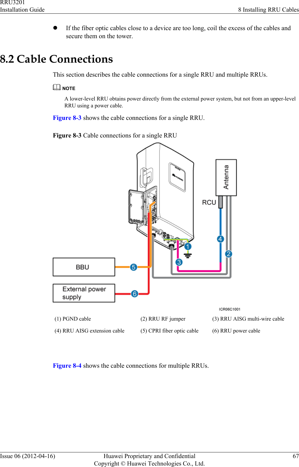
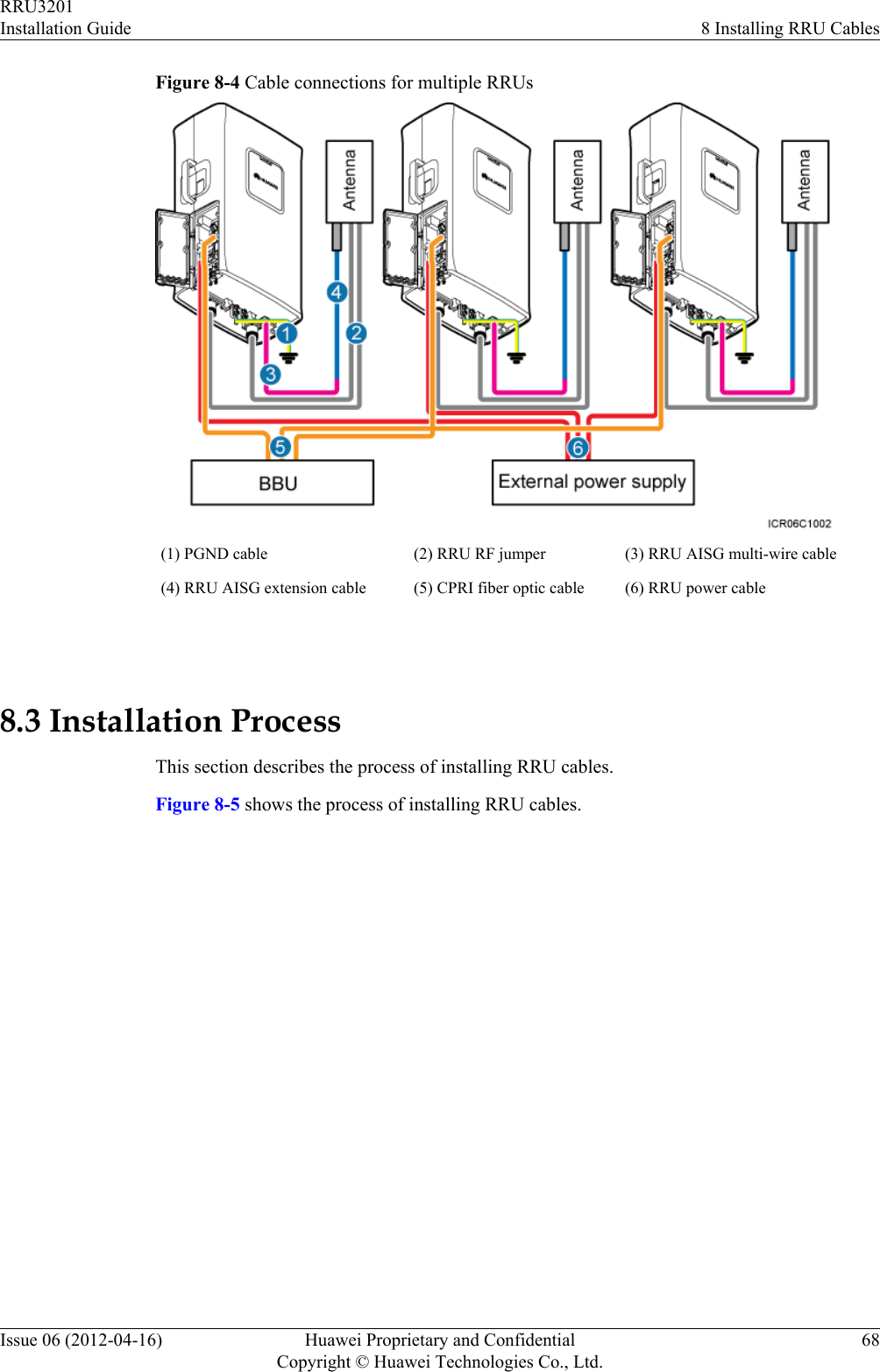
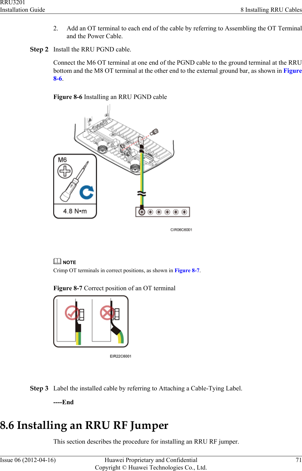
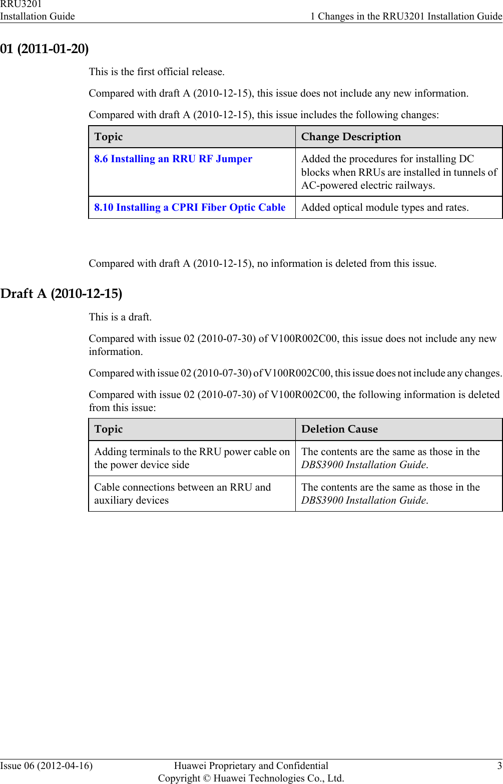
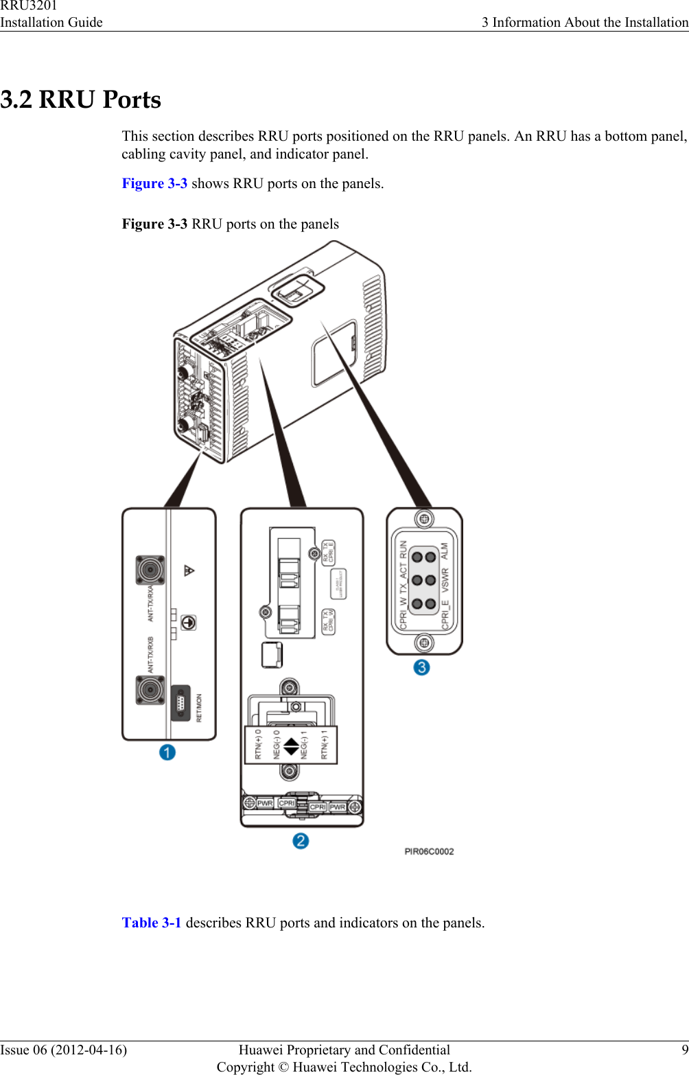
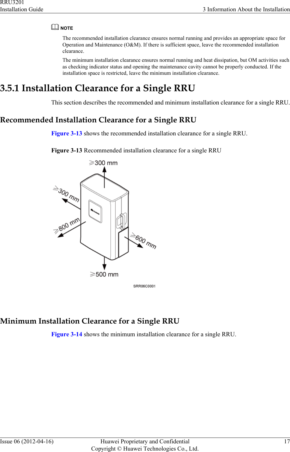
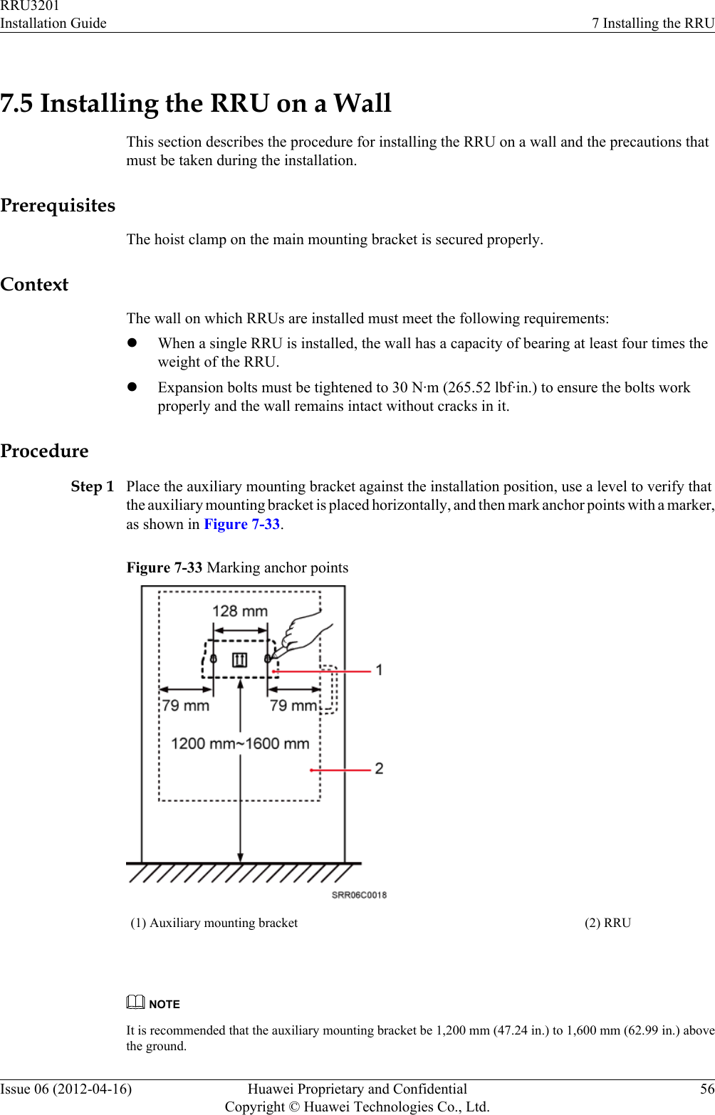
![Figure 8-5 Process of installing RRU cables 8.4 RRU Cable ListThis section describes RRU cable connections.Table 8-1 lists RRU cables.Table 8-1 RRU cablesCable One End The Other EndConnector InstallationPositionConnector InstallationPositionRRU PGNDCableOT terminal(M6, 16 mm2[0.025 in.2])Groundterminal on theRRUOT terminal (M8,16 mm2 [0.025 in.2])Ground terminalon the ground barRRU PowerCableOT terminal(M4, 3.3 mm2[0.005 in.2]),complying withNEG(-) andRTN(+) portson the RRUTool-less femaleconnector(pressfit type)One of RRU0 toRRU5 ports onthe EPU or EPSRRU3201Installation Guide 8 Installing RRU CablesIssue 06 (2012-04-16) Huawei Proprietary and ConfidentialCopyright © Huawei Technologies Co., Ltd.69](https://usermanual.wiki/Huawei-Technologies/RRU3201-B13.UserManual-Installation-pdf/User-Guide-2196921-Page-77.png)
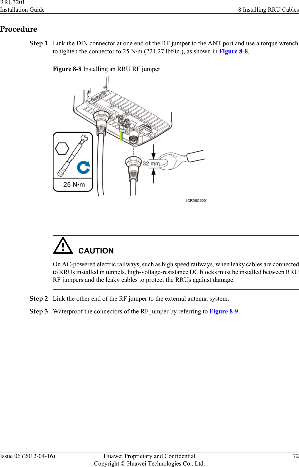
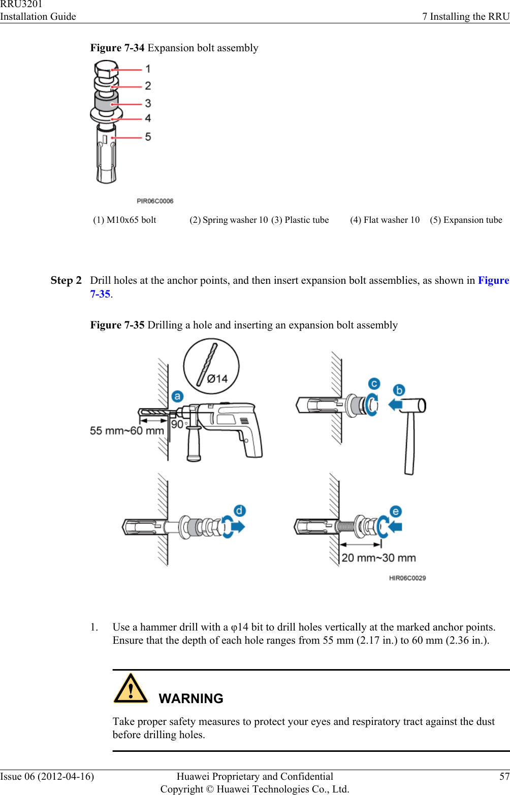
![Cable One End The Other EndConnector InstallationPositionConnector InstallationPositionNorth AmericanstandardsOT terminal(M4, 4 mm2[0.006 in.2]),complying withEuropeanstandardsOT terminal (M4,3.3 mm2 [0.005in.2]), complyingwith NorthAmericanstandardsOT terminal (M4,4 mm2 [0.006 in.2]), complyingwith EuropeanstandardsOne of LOAD0 toLOAD5 ports onthe DCDUOne of LOAD4 toLOAD9 ports onthe PDUCPRI FiberOptic CableDLC connector CPRI_W porton the RRUDLC connector CPRI port on theLBBP in the BBURRU RFJumperDIN maleconnectorANT-TX/RXAor ANT-TX/RXB port on theRRUDIN maleconnectorAntenna systemRRU AISGMulti-WireCableWaterproofedDB9 maleconnectorRET/MON porton the RRUStandard AISGfemale connectorStandard AISGmale connector onthe RCU or on theAISG extensioncableRRU AISGExtensionCableStandard AISGmale connectorStandard AISGfemaleconnector onthe AISG multi-wire cableStandard AISGfemale connectorStandard AISGmale connector onthe RCU 8.5 Installing an RRU PGND CableThis section describes the procedure for installing an RRU PGND cable.ContextThe cross-sectional area of an RRU PGND cable is 16 mm2 (0.025 in.2). The OT terminals attwo ends of the cable are M6 and M8 terminals respectively.ProcedureStep 1 Prepare an RRU PGND cable.1. Cut the cable to the required length based on the actual cable route.RRU3201Installation Guide 8 Installing RRU CablesIssue 06 (2012-04-16) Huawei Proprietary and ConfidentialCopyright © Huawei Technologies Co., Ltd.70](https://usermanual.wiki/Huawei-Technologies/RRU3201-B13.UserManual-Installation-pdf/User-Guide-2196921-Page-78.png)