Huawei Technologies RRU3232-3650F LTE Remote Radio Unit User Manual Installation Guide
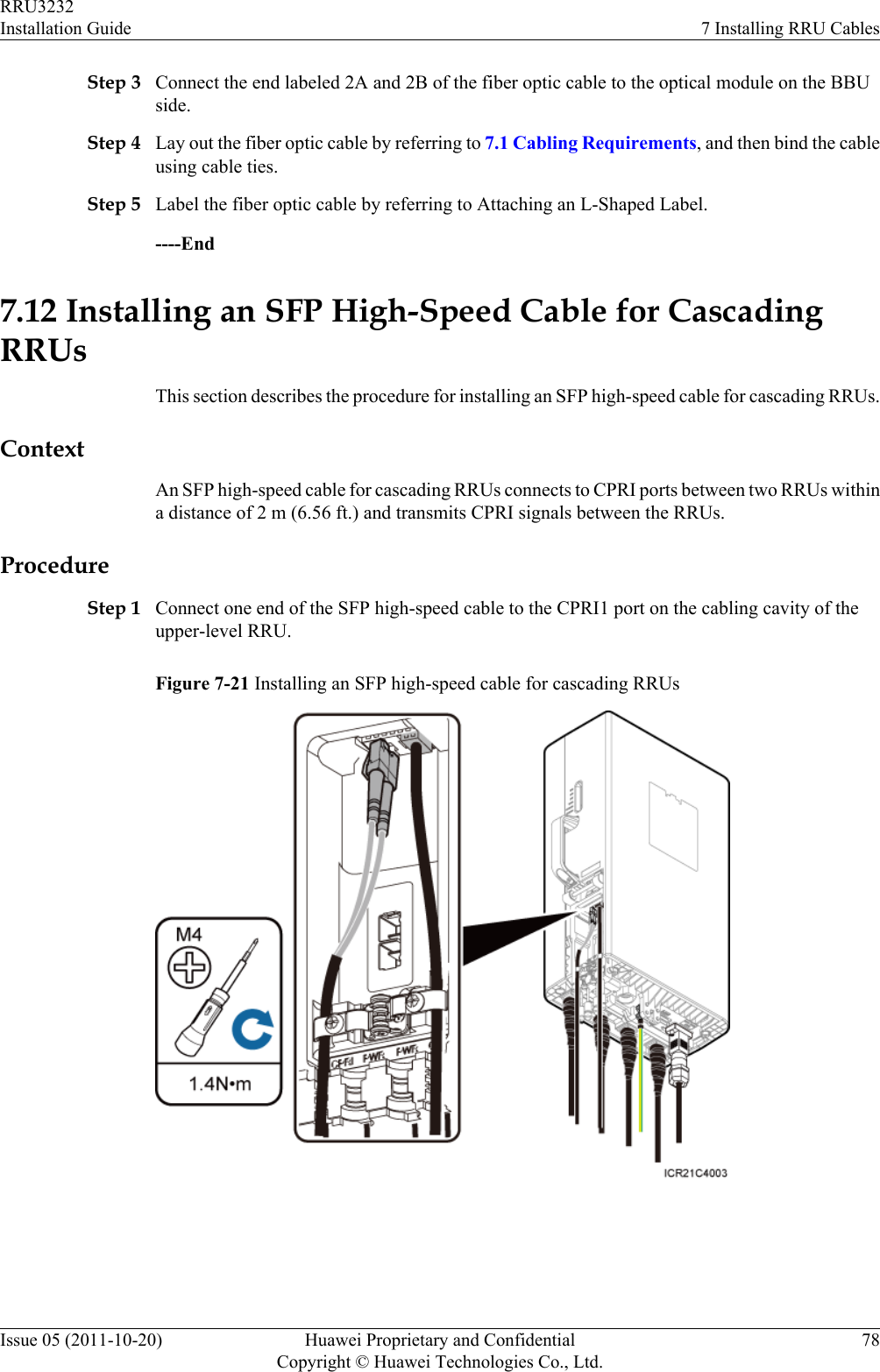
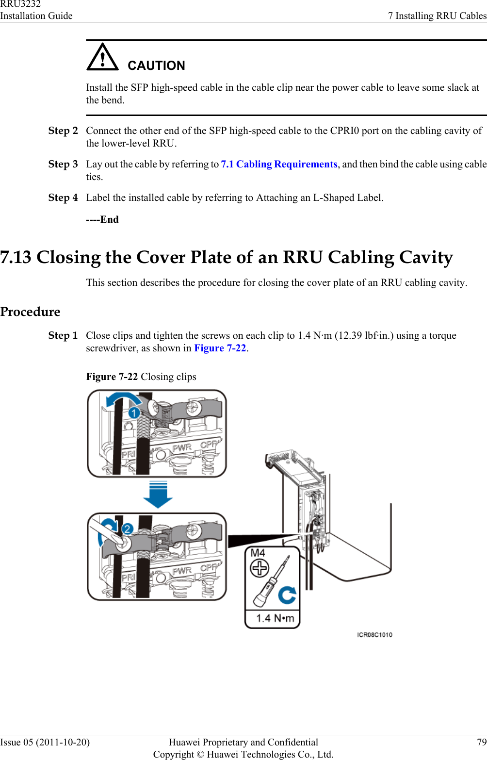
Huawei Technologies Co.,Ltd LTE Remote Radio Unit Installation Guide
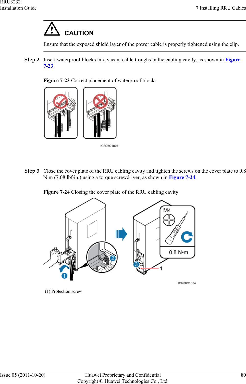
UserManual.wiki
>
Huawei Technologies
>
RRU3232-3650F User Manual
>
Installation Guide
Contents
1.
Installation Guide
2.
Safety information
Installation Guide
Navigation menu
Upload a User Manual
Namespaces
Wiki Guide
HTML
PDF
Info
Views
User Manual
Discussion / Help
Navigation
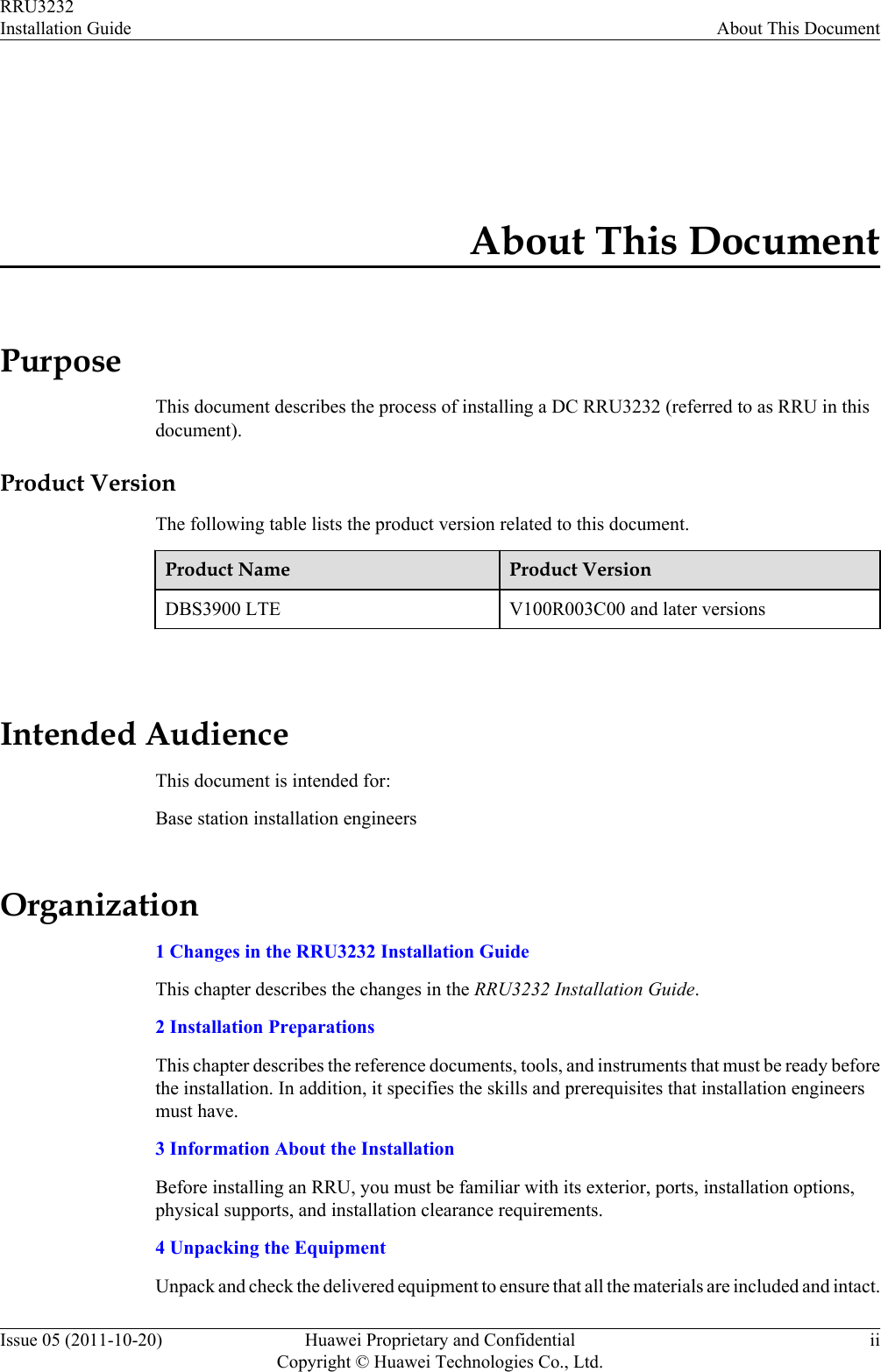
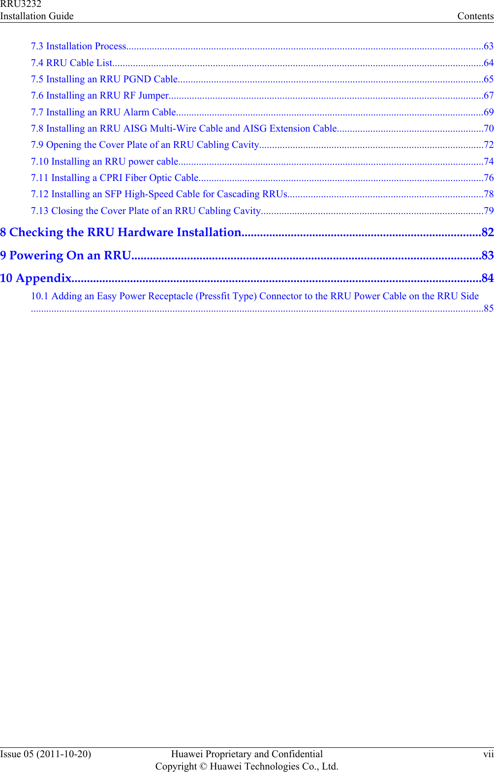
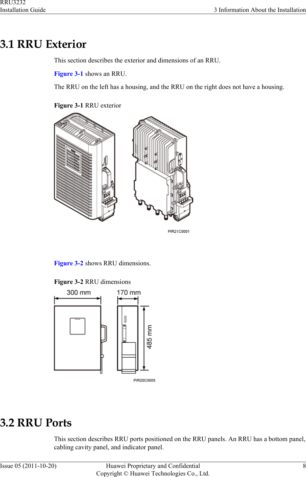
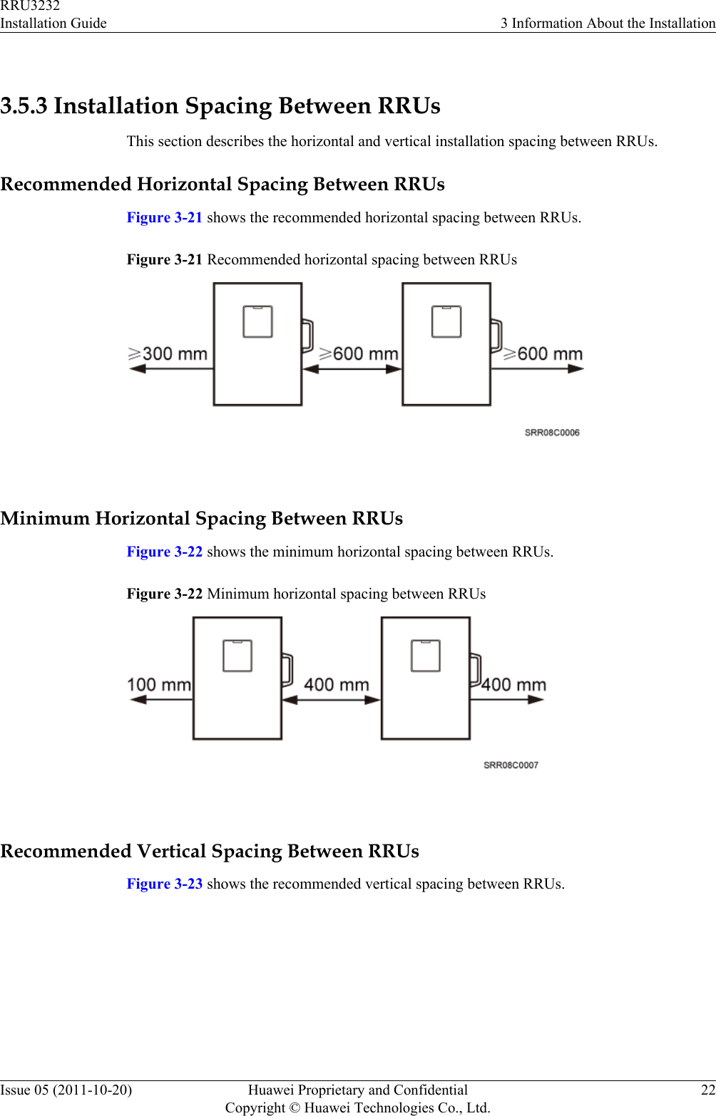
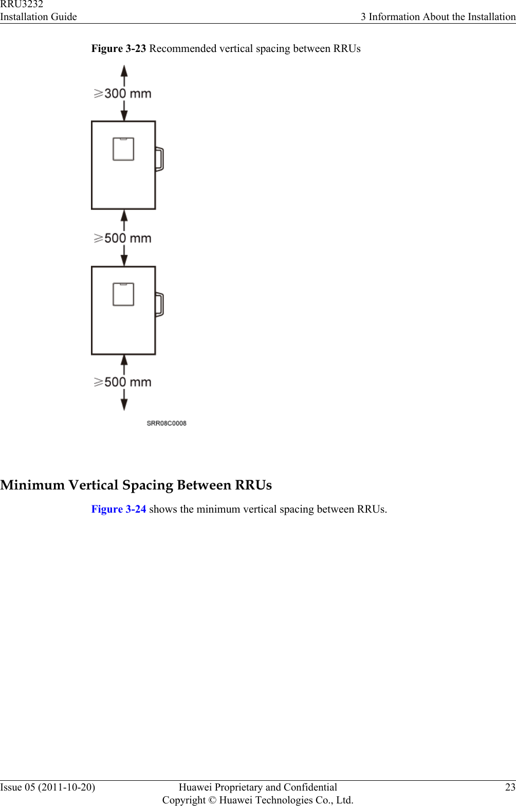
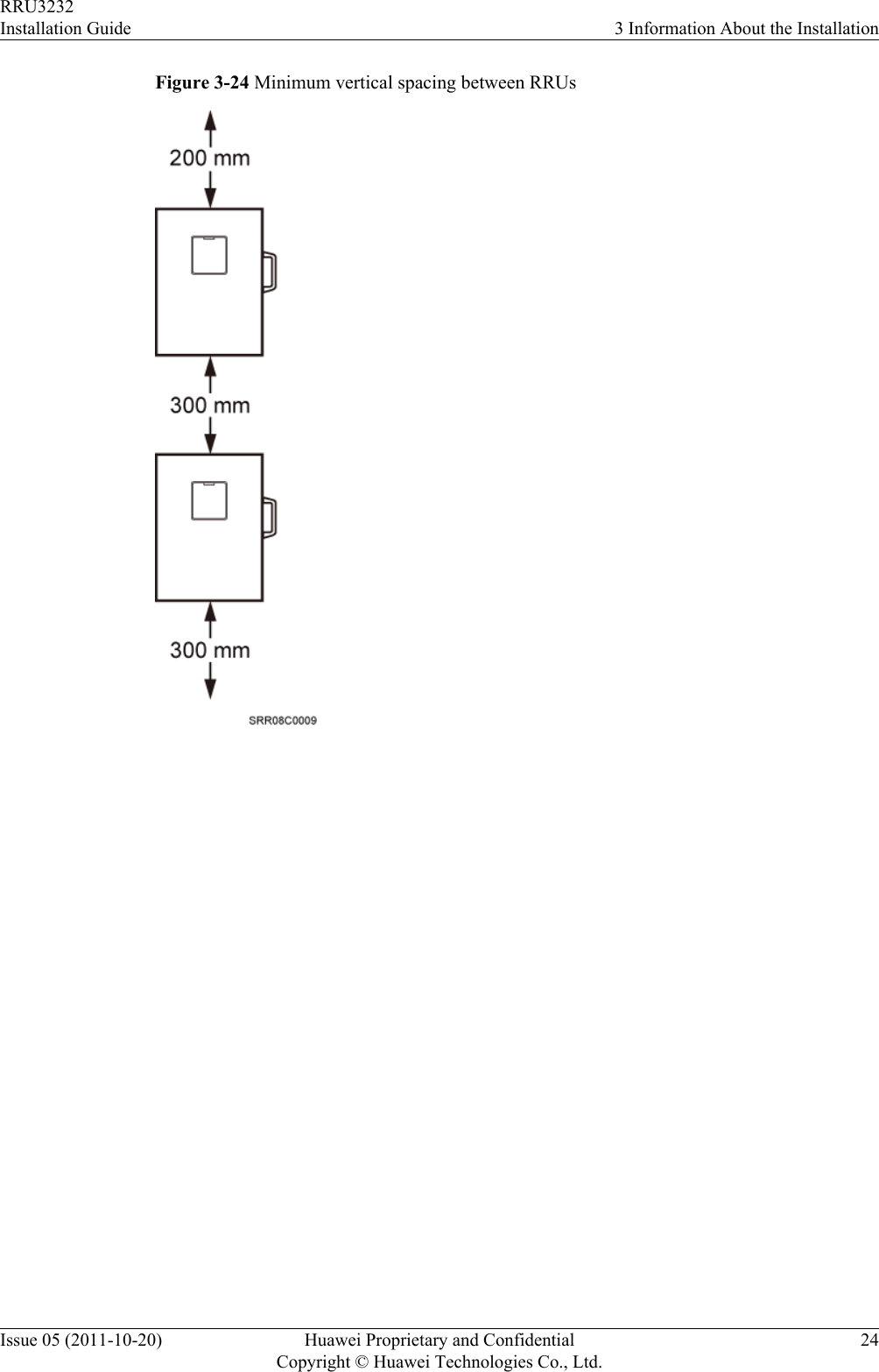
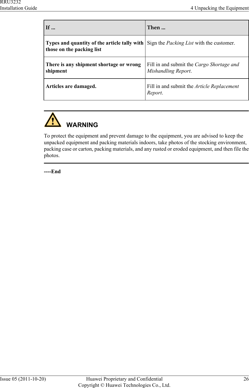
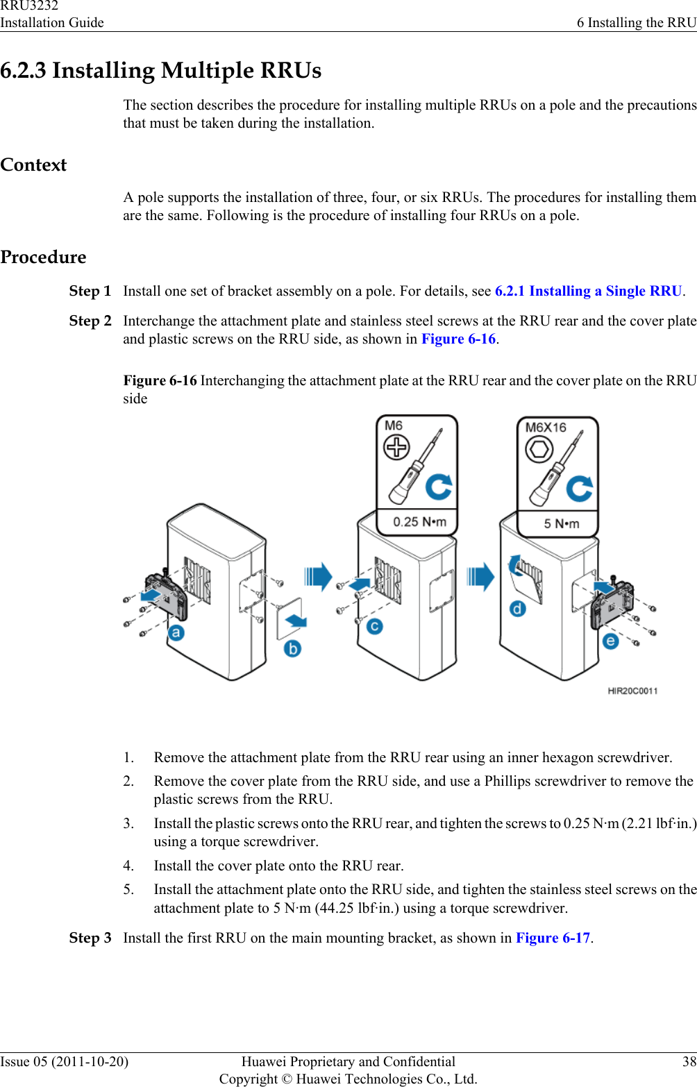
![Convention DescriptionTimes New Roman Normal paragraphs are in Times New Roman.Boldface Names of files, directories, folders, and users are inboldface. For example, log in as user root.Italic Book titles are in italics.Courier New Examples of information displayed on the screen are inCourier New. Command ConventionsThe command conventions that may be found in this document are defined as follows.Convention DescriptionBoldface The keywords of a command line are in boldface.Italic Command arguments are in italics.[ ] Items (keywords or arguments) in brackets [ ] are optional.{ x | y | ... } Optional items are grouped in braces and separated byvertical bars. One item is selected.[ x | y | ... ] Optional items are grouped in brackets and separated byvertical bars. One item is selected or no item is selected.{ x | y | ... }*Optional items are grouped in braces and separated byvertical bars. A minimum of one item or a maximum of allitems can be selected.[ x | y | ... ]*Optional items are grouped in brackets and separated byvertical bars. Several items or no item can be selected. GUI ConventionsThe GUI conventions that may be found in this document are defined as follows.Convention DescriptionBoldface Buttons, menus, parameters, tabs, window, and dialog titlesare in boldface. For example, click OK.>Multi-level menus are in boldface and separated by the ">"signs. For example, choose File > Create > Folder. Keyboard OperationsThe keyboard operations that may be found in this document are defined as follows.RRU3232Installation Guide About This DocumentIssue 05 (2011-10-20) Huawei Proprietary and ConfidentialCopyright © Huawei Technologies Co., Ltd.iv](https://usermanual.wiki/Huawei-Technologies/RRU3232-3650F.Installation-Guide/User-Guide-3256886-Page-5.png)
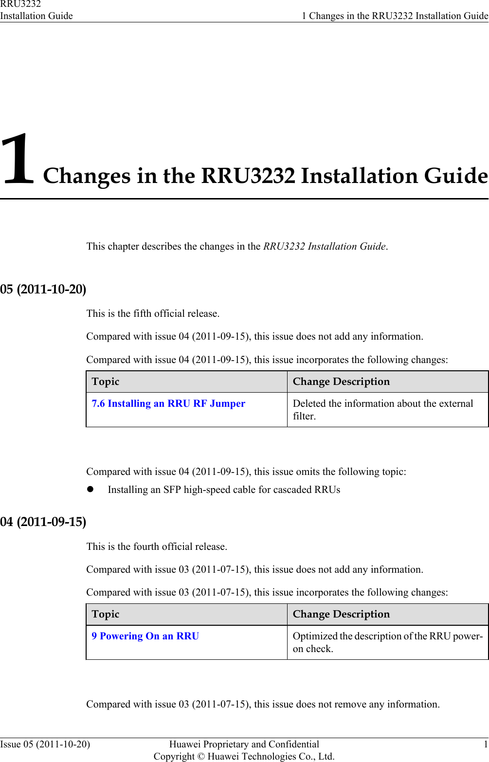
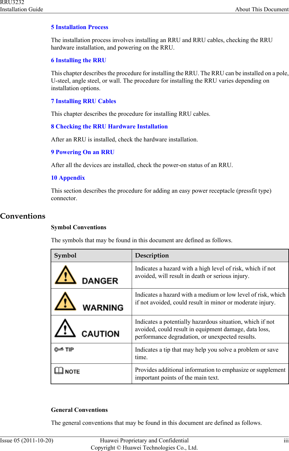
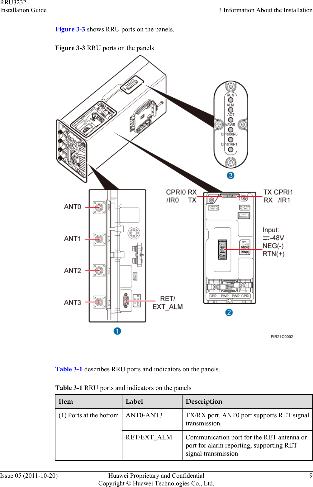
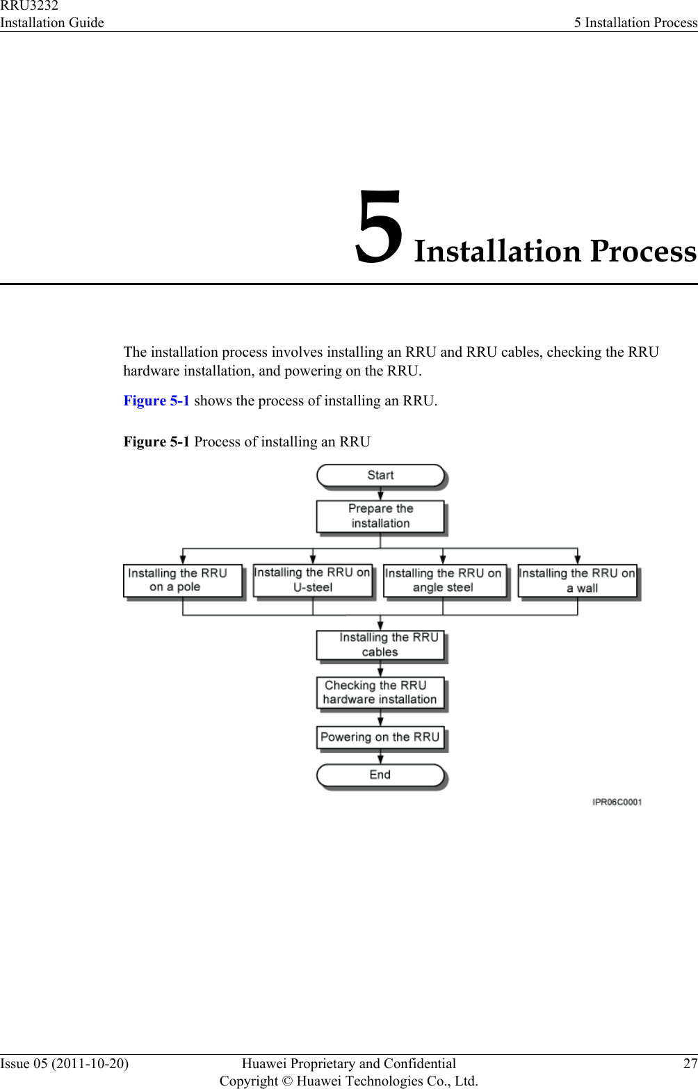
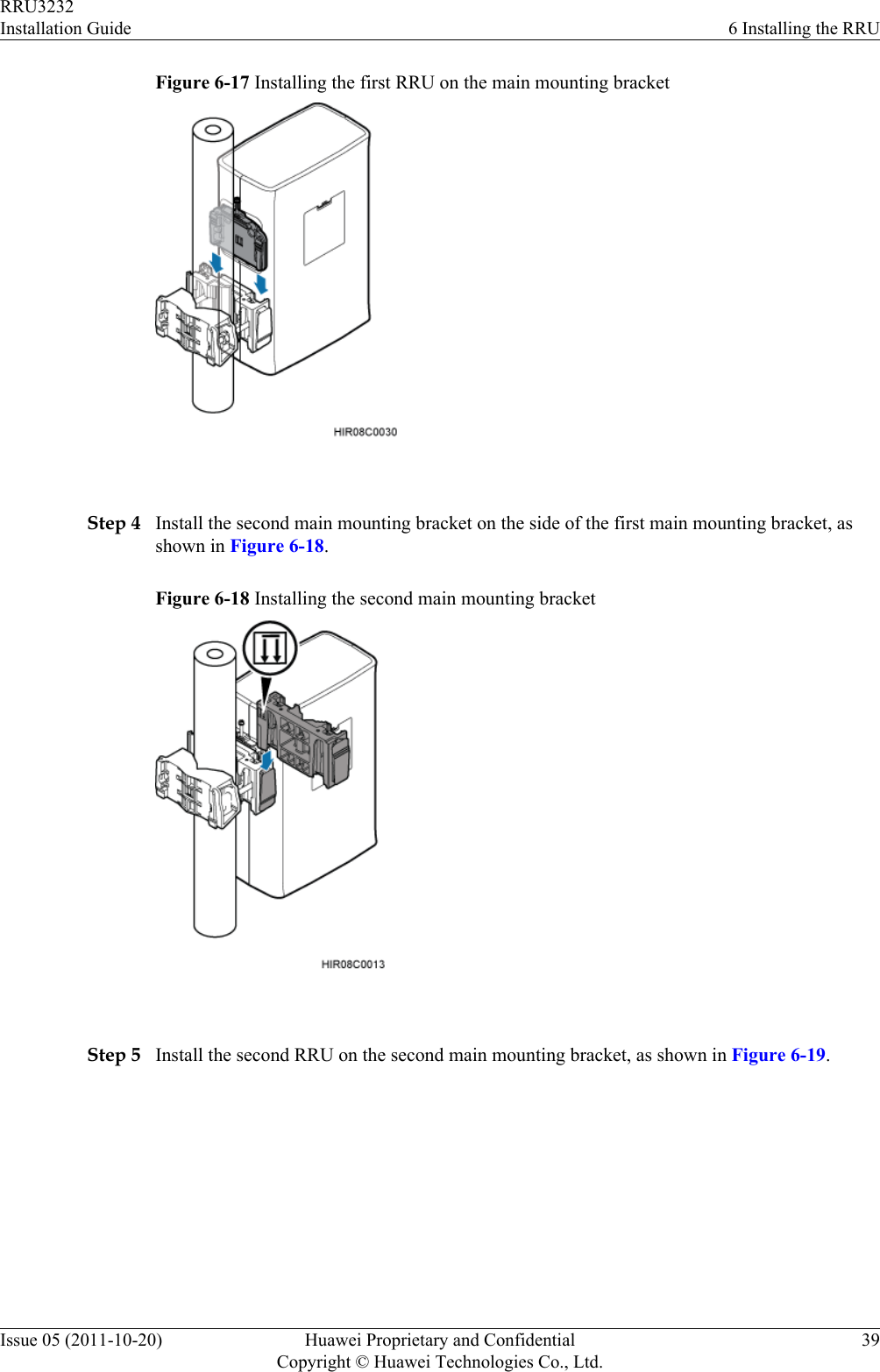
![2.1 Reference DocumentsBefore the installation, you must be familiar with reference documents.The following reference documents are required during RRU installation:lRRU3232 Hardware DescriptionlRRU3232 Hardware Maintenance GuidelDBS3900 Installation GuidelOCB User GuideThis document describes the RRU installation on a pole, U-steel, angle steel, or wall. If RRUsare installed on the IFS06, the following reference document is required:lDBS3900 (ICR) Installation Guide2.2 Tools and InstrumentsAll tools and instruments required for RRU installation must be ready before the installation.Hammer drill (a φ 14 bit) ESD gloves Vacuum cleanerHeat gun Phillips screwdriver (M3 toM6)Flat-head screwdriver (M3 toM6)Rubber mallet COAX crimping tool Wire stripperUtility knife Cable cutter Adjustable wrench (capacity≥ 32 mm [1.26 in.])RRU3232Installation Guide 2 Installation PreparationsIssue 05 (2011-10-20) Huawei Proprietary and ConfidentialCopyright © Huawei Technologies Co., Ltd.5](https://usermanual.wiki/Huawei-Technologies/RRU3232-3650F.Installation-Guide/User-Guide-3256886-Page-13.png)
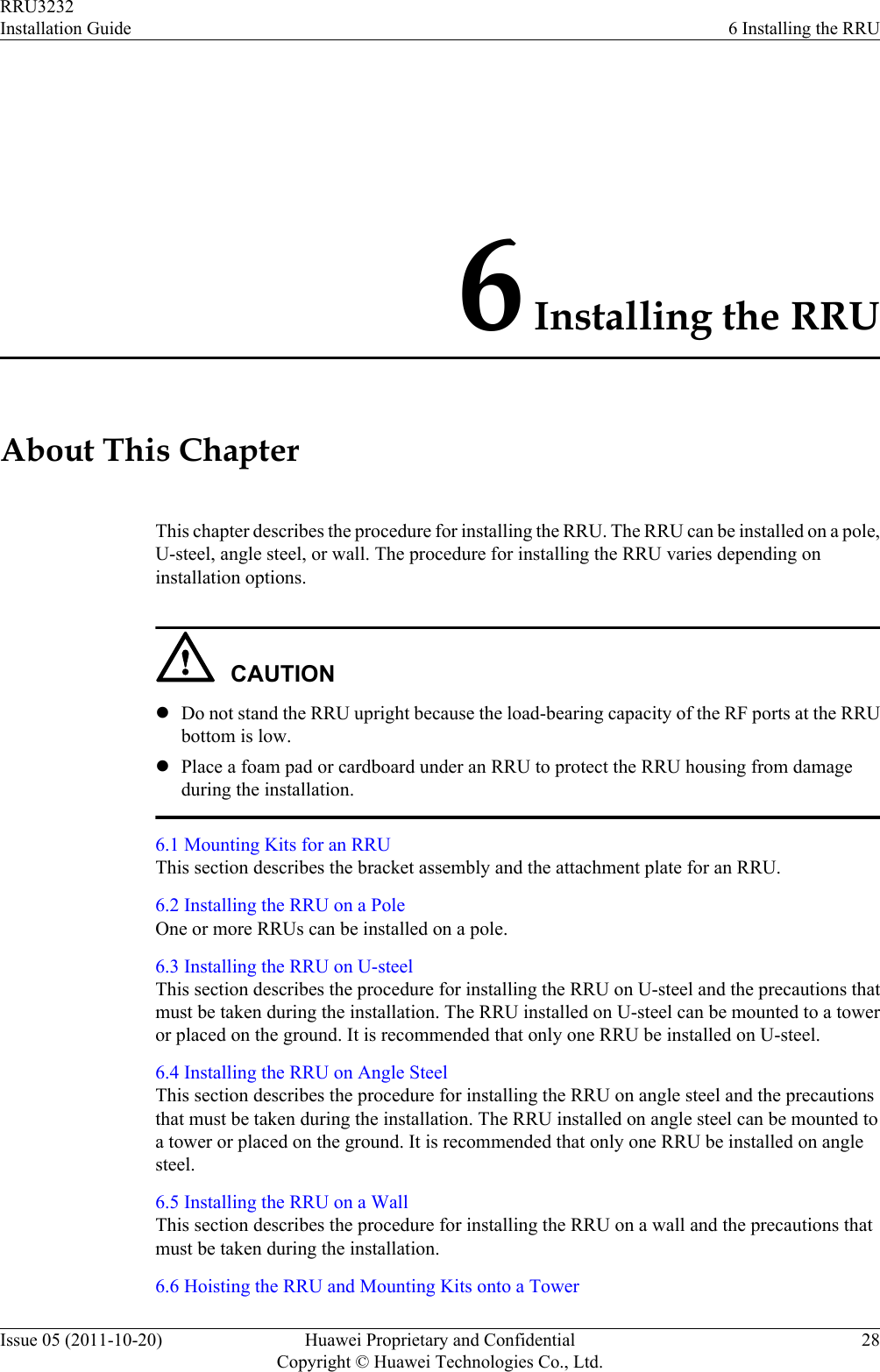
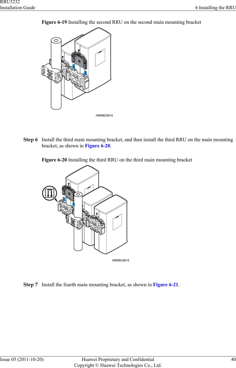
![Level Torque screwdriver5 mm(M3 to M6)(M3 to M6)Torque wrenchCapacity: 17 mm [0.67 in.], 21mm [0.82 in.], and 32 mm[1.26 in.]Combination wrenchCapacity: 17 mm [0.67 in.], 21mm [0.82 in.], and 32 mm[1.26 in.]Multimeter Marker (diameter ≤ 10 mm[0.39 in.])Measuring tape 2.3 Skills and Requirements for Onsite PersonnelOnsite personnel must be qualified and trained. Before performing any operation, onsitepersonnel must be familiar with correct operation methods and safety precautions.Before the installation, pay attention to the following items:lThe customer's technical engineers must be trained by Huawei and be familiar with theproper installation and operation methods.lThe number of onsite personnel depends on the engineering schedule and installationenvironment. Generally, only three to five onsite personnel are necessary.RRU3232Installation Guide 2 Installation PreparationsIssue 05 (2011-10-20) Huawei Proprietary and ConfidentialCopyright © Huawei Technologies Co., Ltd.6](https://usermanual.wiki/Huawei-Technologies/RRU3232-3650F.Installation-Guide/User-Guide-3256886-Page-14.png)
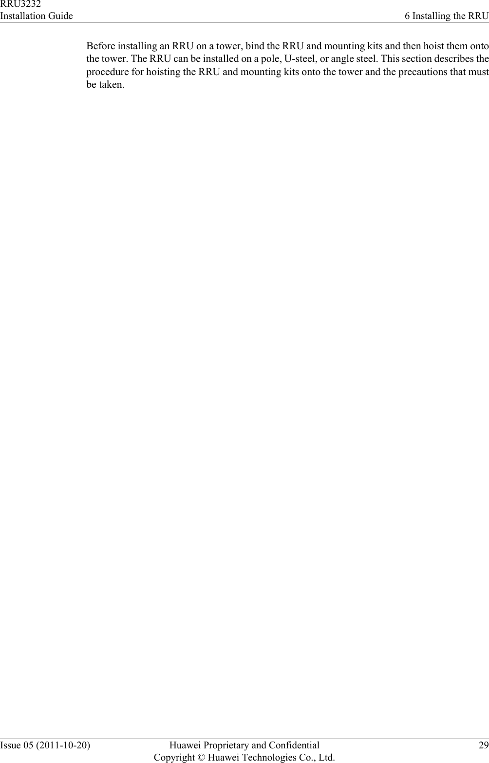
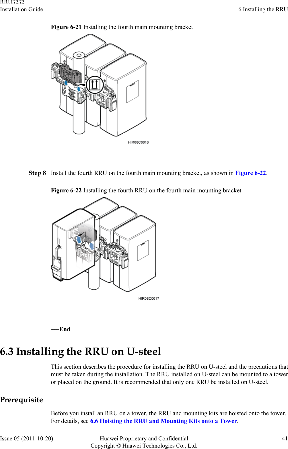
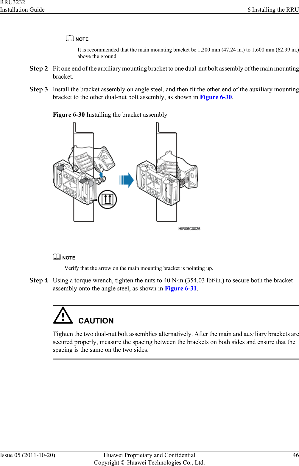
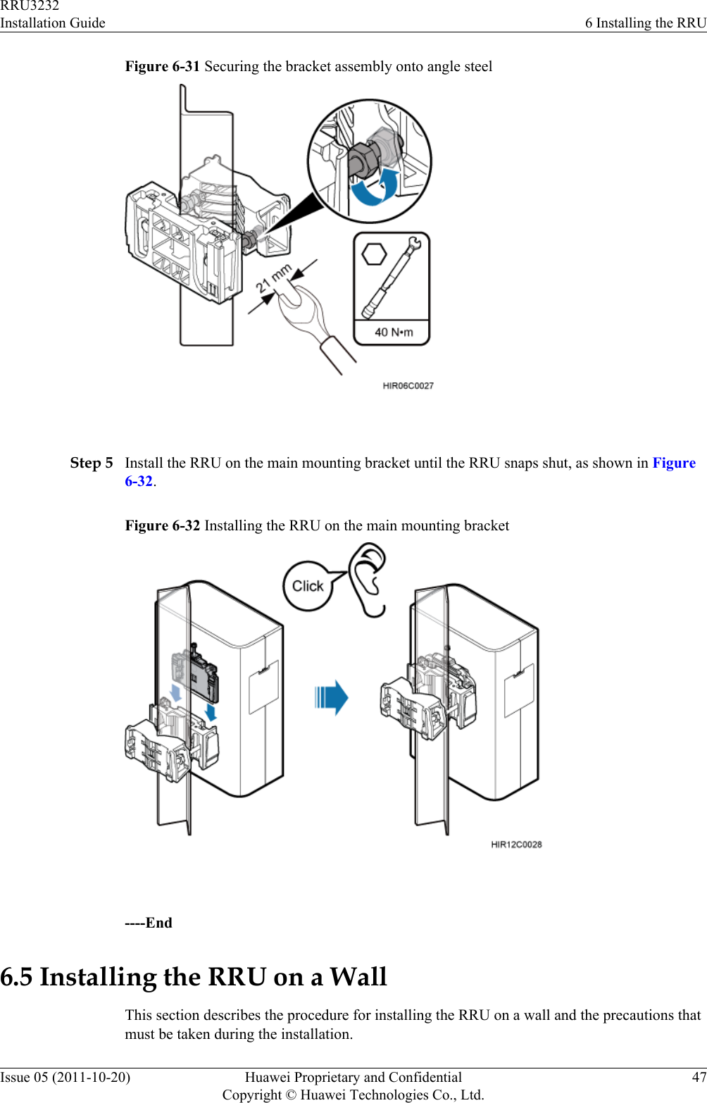

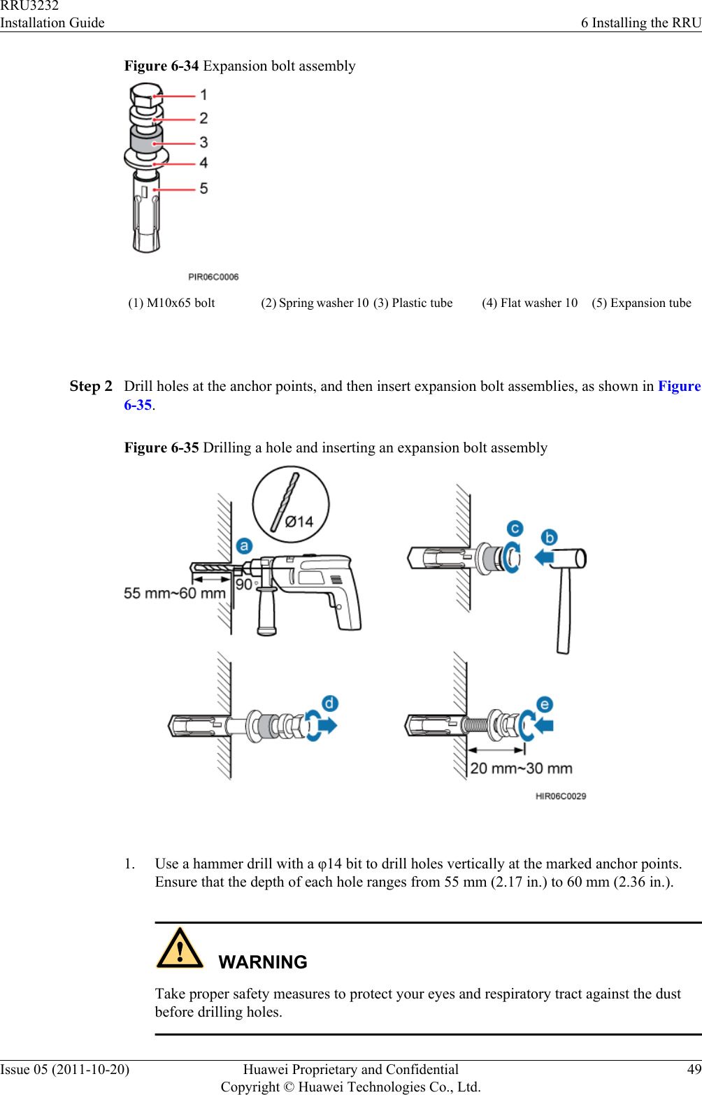
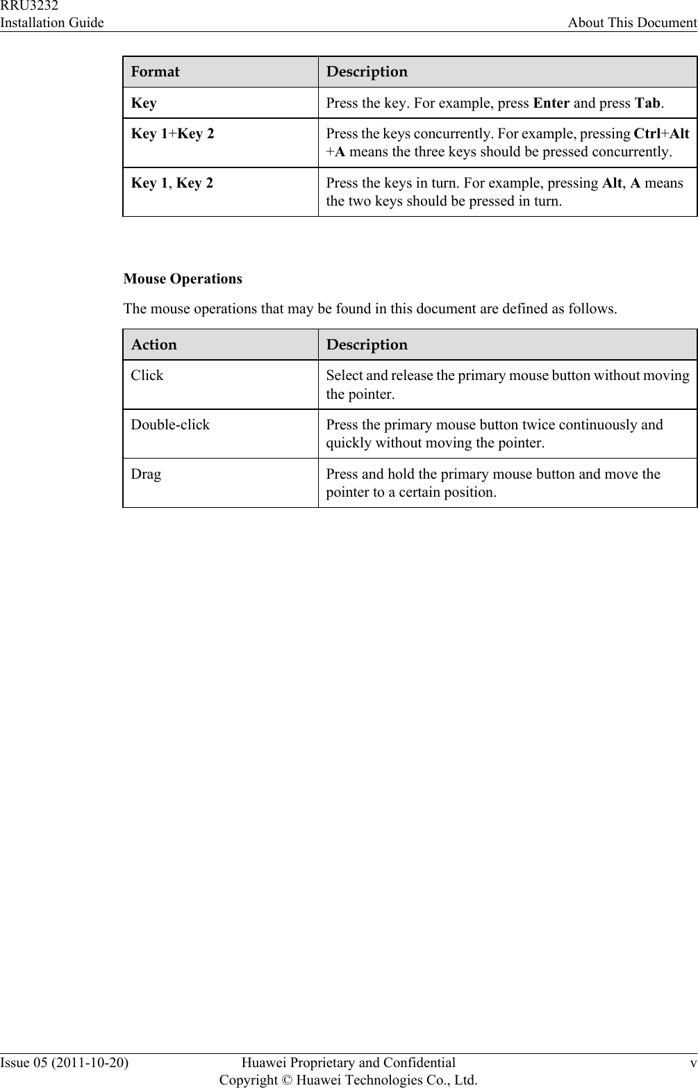
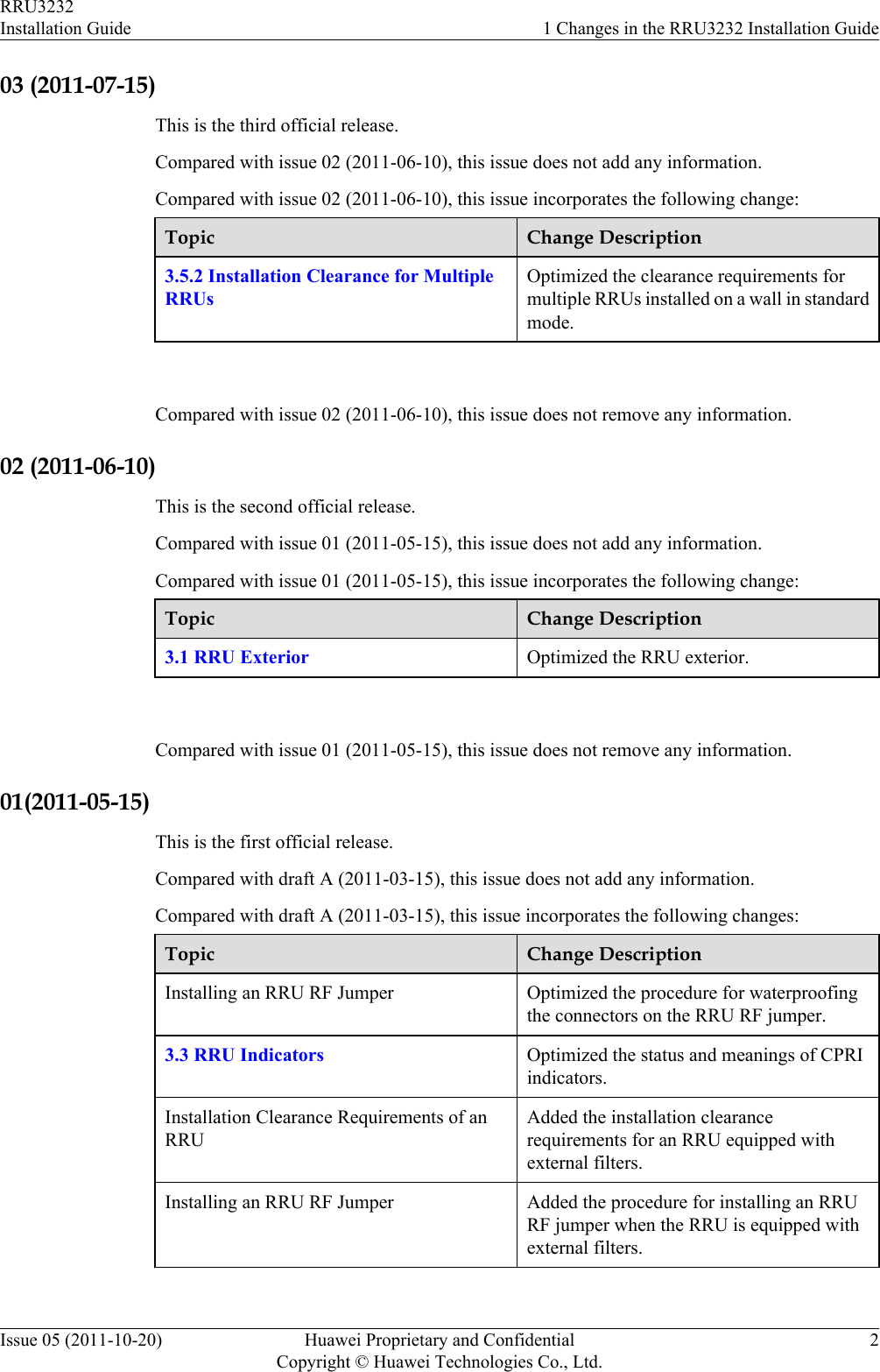
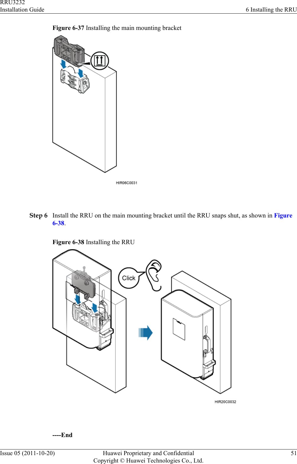
![2. Hit the expansion bolt with a rubber mallet until the expansion tube completely enters thehole.3. Tighten an expansion bolt slightly and place it vertically into each hole.4. Remove the M10x65 bolt, spring washer, plastic tube, and flat washer from each expansionbolt assembly in sequence.NOTEAfter completely removing an expansion bolt, store the plastic tube properly.5. Hammer the bolt into the wall.CAUTIONDo not hammer the expansion bolt entirely into the wall. Instead, leave 20 mm (0.79 in.)to 30 mm (1.18 in.) of the expansion bolt outside the wall.Step 3 Fit the auxiliary mounting bracket on the expansion bolt, and then use a torque wrench (17 mm[0.67 in.]) to tighten the expansion bolt to 30 N·m (265.52 lbf·in.), as shown in Figure 6-36.Figure 6-36 Fitting the auxiliary mounting bracket on expansion bolts CAUTIONVerify that the arrow on the auxiliary mounting bracket is pointing up.Step 4 Loosen the screws on the main mounting bracket and store them properly.Step 5 Install the main mounting bracket, as shown in Figure 6-37.RRU3232Installation Guide 6 Installing the RRUIssue 05 (2011-10-20) Huawei Proprietary and ConfidentialCopyright © Huawei Technologies Co., Ltd.50](https://usermanual.wiki/Huawei-Technologies/RRU3232-3650F.Installation-Guide/User-Guide-3256886-Page-58.png)

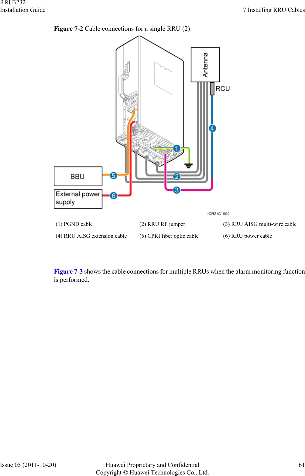
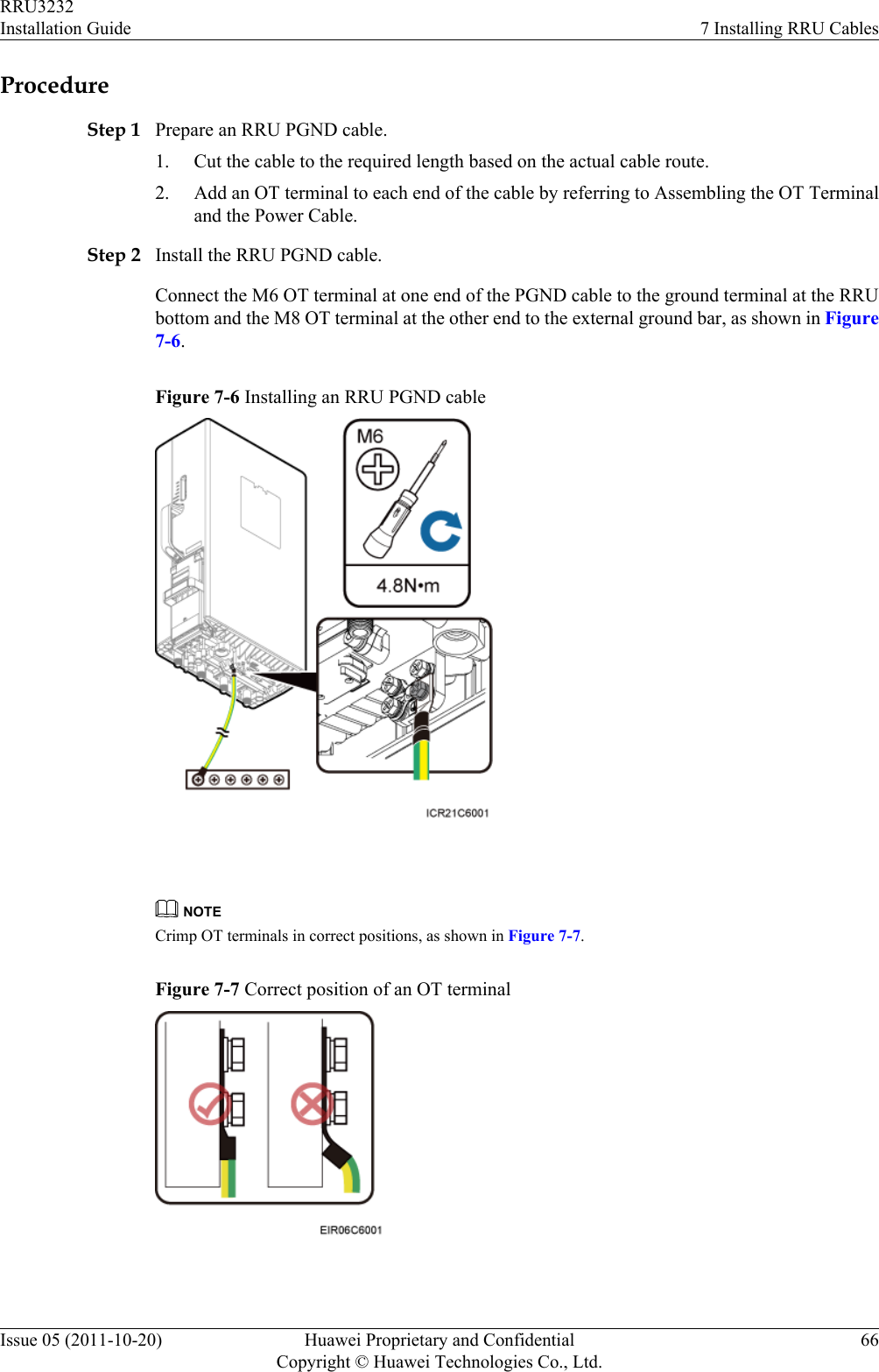
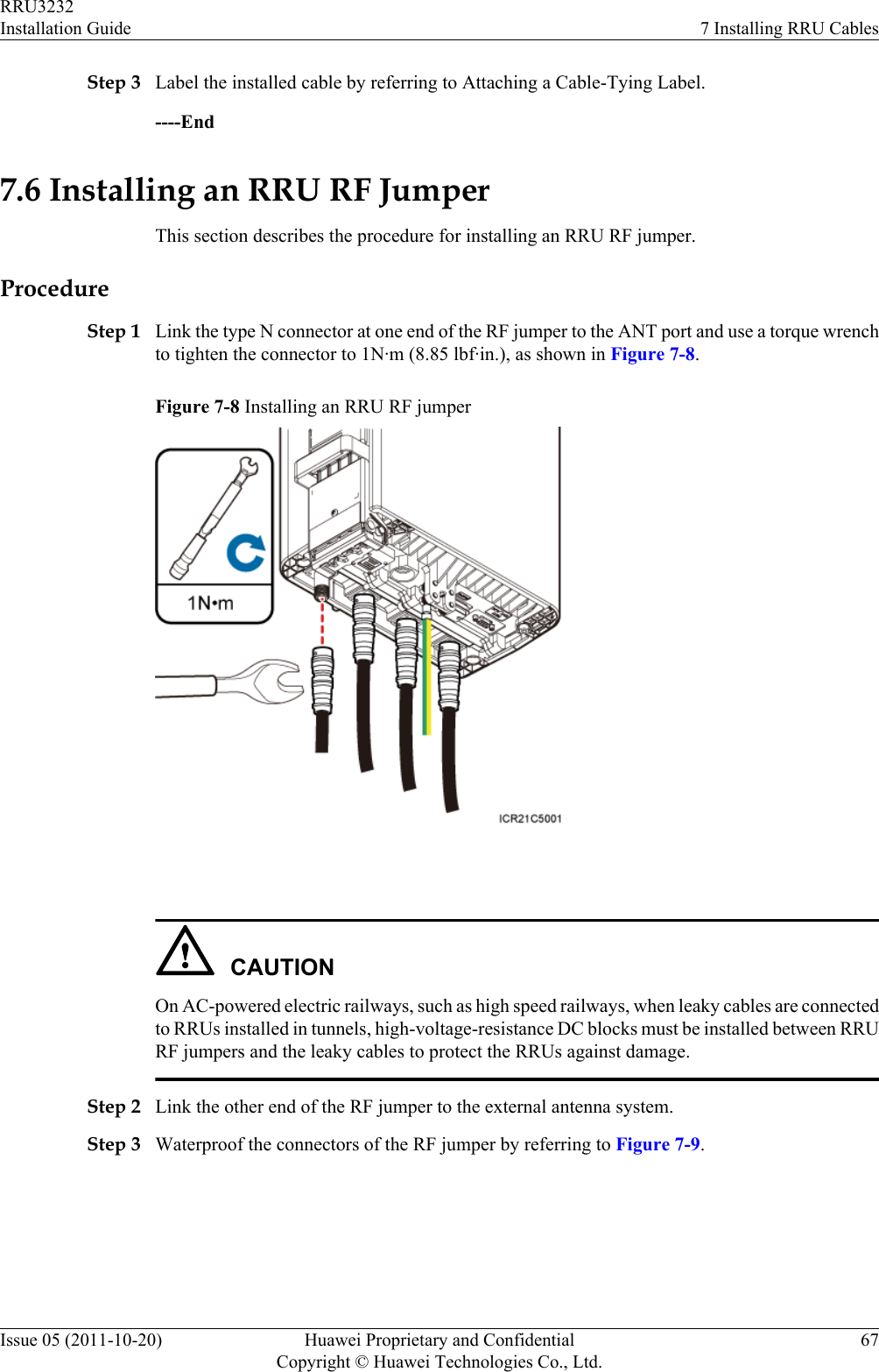
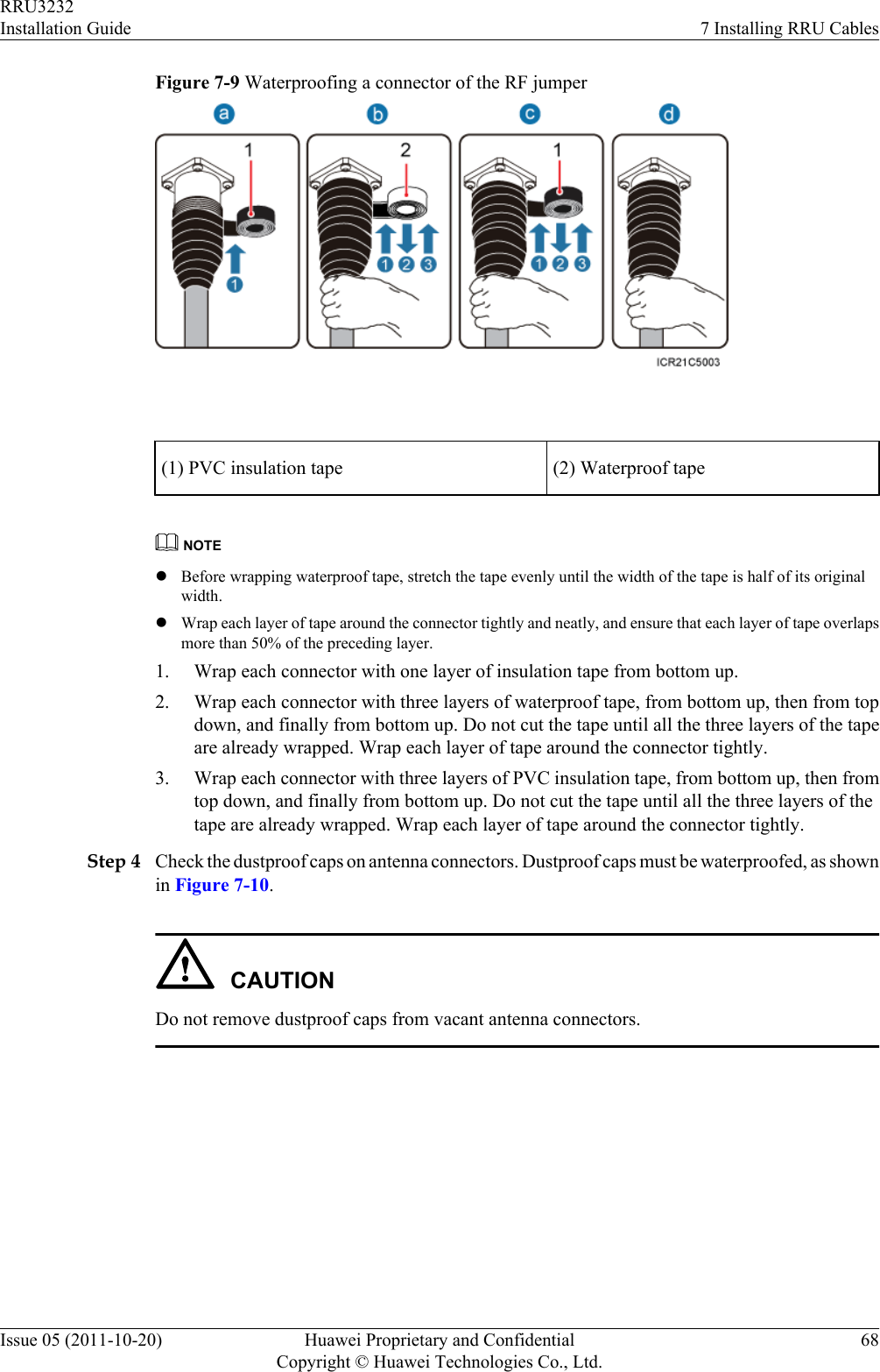
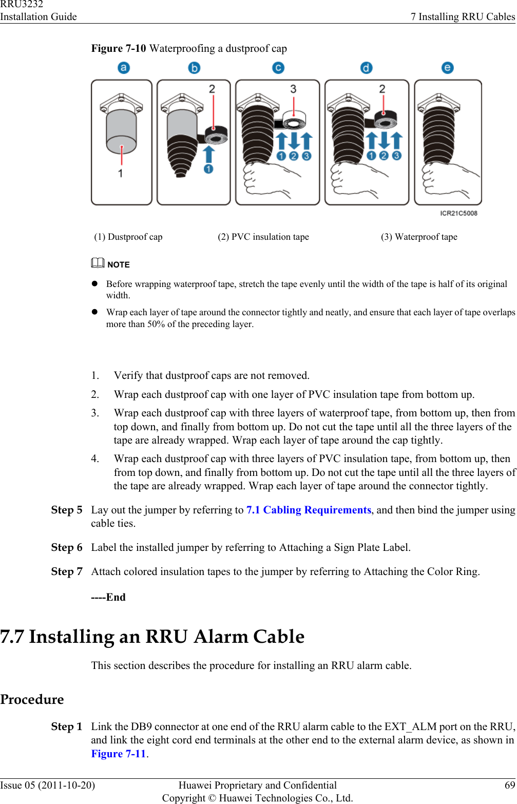
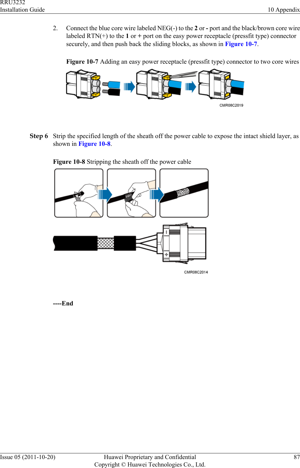
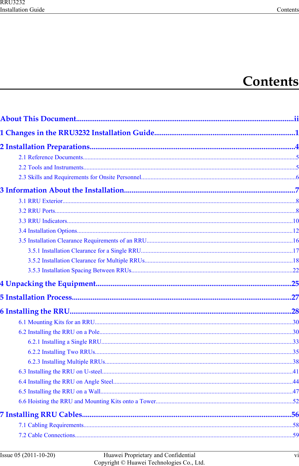
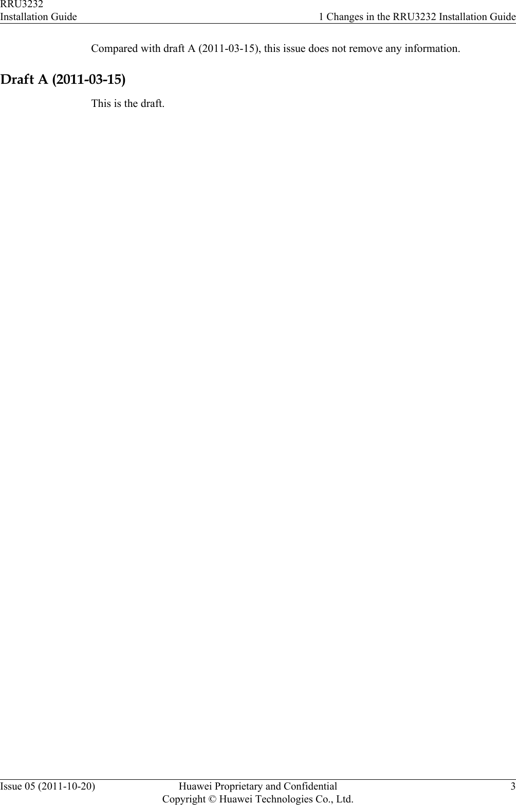
![Figure 7-5 Process of installing RRU cables 7.4 RRU Cable ListThis section describes RRU cable connections.Table 7-1 lists RRU cables.Table 7-1 RRU cablesCable One End The Other EndConnector InstallationPositionConnector InstallationPositionRRU PGNDCableOT terminal(M6, 16 mm2[0.025 in.2])Groundterminal on theRRUOT terminal (M8,16 mm2 [0.025 in.2])Ground terminalon the ground barRRU PowerCableEasy powerreceptacle(pressfit type)connectorNEG(-) andRTN(+) portson the RRUEasy powerreceptacle(pressfit type)connectorRRU0 to RRU5on the EPSRRU3232Installation Guide 7 Installing RRU CablesIssue 05 (2011-10-20) Huawei Proprietary and ConfidentialCopyright © Huawei Technologies Co., Ltd.64](https://usermanual.wiki/Huawei-Technologies/RRU3232-3650F.Installation-Guide/User-Guide-3256886-Page-72.png)
![Cable One End The Other EndConnector InstallationPositionConnector InstallationPositionOT terminal (M4,3.3 mm2 [0.005in.2]), complyingwith NorthAmericanstandardsOT terminal (M4,4 mm2 [0.006 in.2]), complyingwith EuropeanstandardsOne of LOAD0 toLOAD5 ports onthe DCDUOne of LOAD4 toLOAD9 ports onthe PDUCPRI FiberOptic CableDLC connector CPRI0/IR0 porton the RRUDLC connector CPRI port on theLBBP in the BBUCPRI1/IR1 porton the RRUCPRI0/IR0 porton the RRURRU RFJumperType NconnectorANT0 to ANT3ports on theRRUType N connector Antenna systemRRU AlarmCableWaterproofedDB9 maleconnectorRET/EXT_ALM porton the RRUCord end terminal External alarmdeviceRRU AISGMulti-WireCableWaterproofedDB9 maleconnectorRET/EXT_ALM porton the RRUStandard AISGfemale connectorStandard AISGmale connectoron the RCU or onthe AISGextension cableRRU AISGExtensionCableStandard AISGmale connectorStandard AISGfemaleconnector on theAISG multi-wire cableStandard AISGfemale connectorStandard AISGmale connectoron the RCU 7.5 Installing an RRU PGND CableThis section describes the procedure for installing an RRU PGND cable.ContextThe cross-sectional area of an RRU PGND cable is 16 mm2 (0.025 in.2). The OT terminals attwo ends of the cable are M6 and M8 terminals respectively.RRU3232Installation Guide 7 Installing RRU CablesIssue 05 (2011-10-20) Huawei Proprietary and ConfidentialCopyright © Huawei Technologies Co., Ltd.65](https://usermanual.wiki/Huawei-Technologies/RRU3232-3650F.Installation-Guide/User-Guide-3256886-Page-73.png)