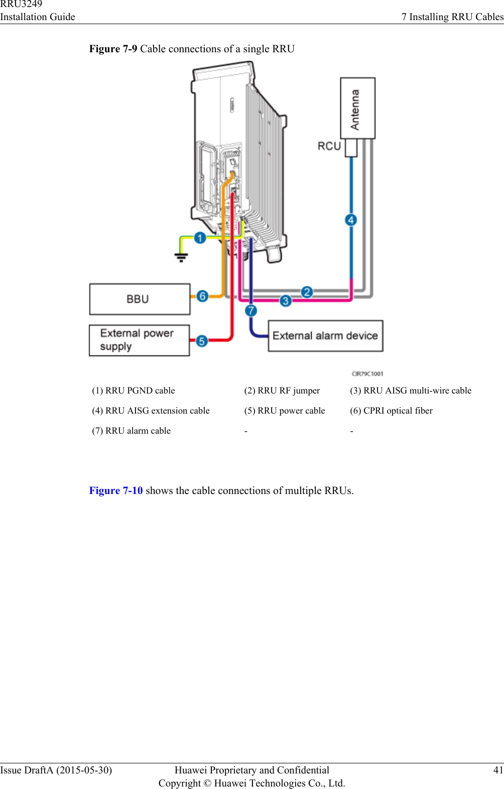
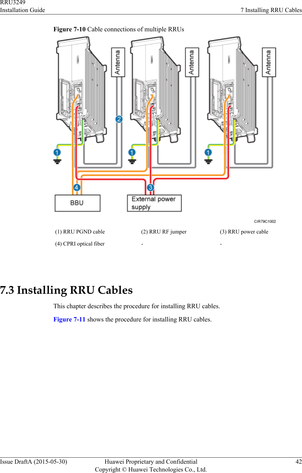
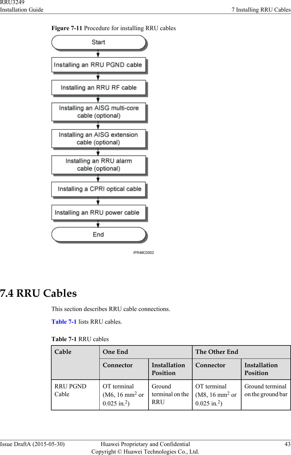
Huawei Technologies RRU3249 Remote Radio Unit User Manual Installation Guide
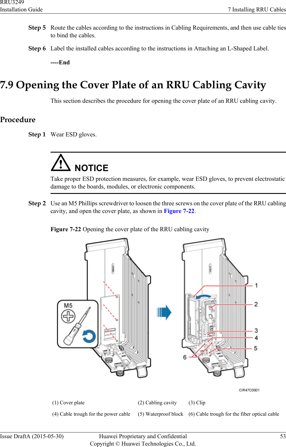
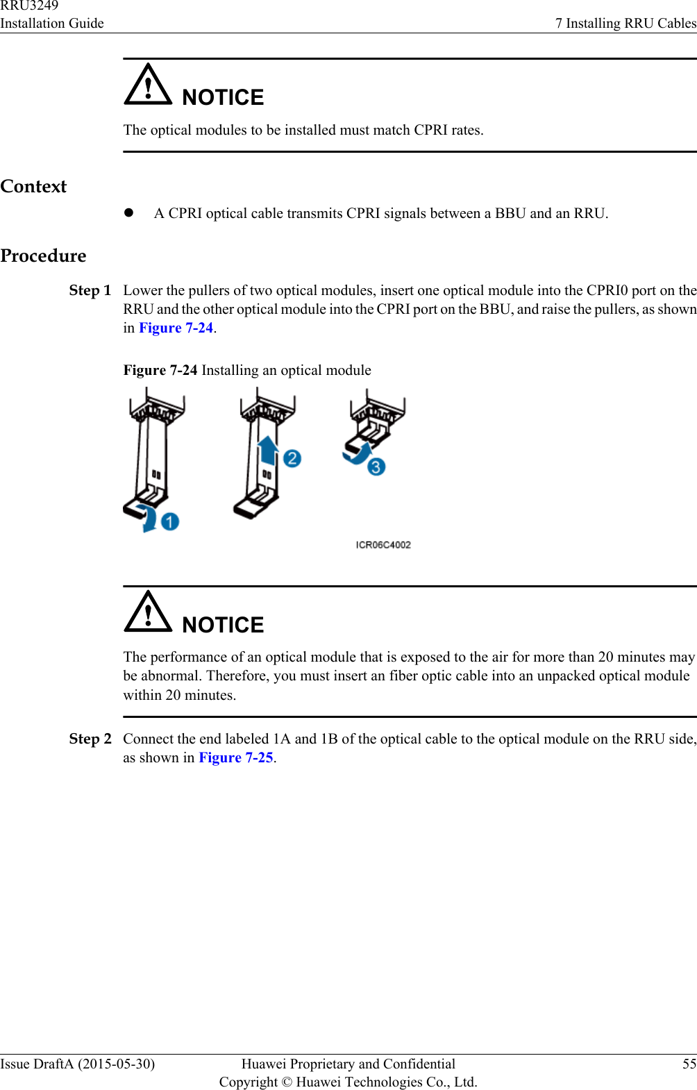
Huawei Technologies Co.,Ltd Remote Radio Unit Installation Guide
Contents
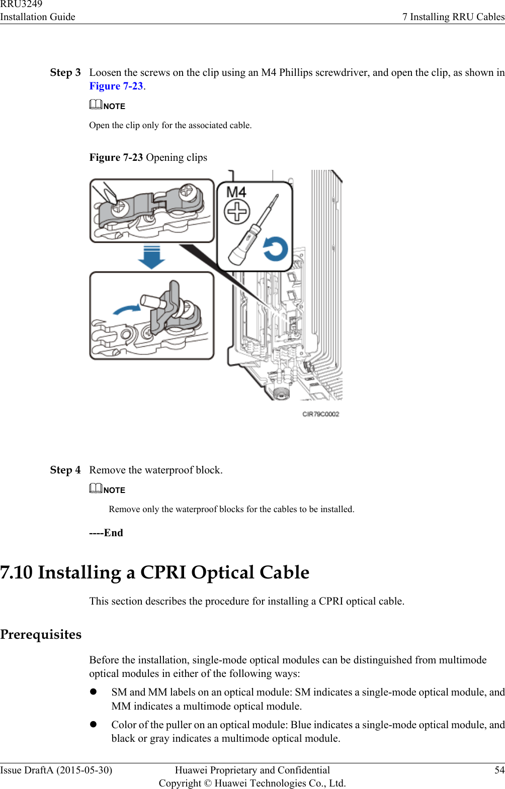
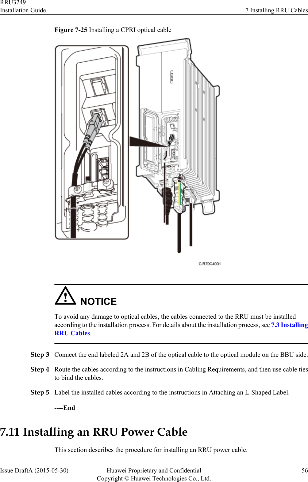
- 1. UserManual_Installation.pdf
- 2. UserManual_RegulatoryNotices.pdf
- 3. UserManual_Safety.pdf
UserManual_Installation.pdf
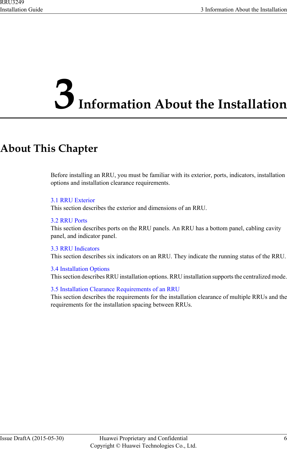
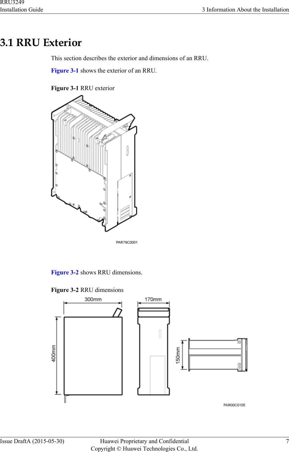
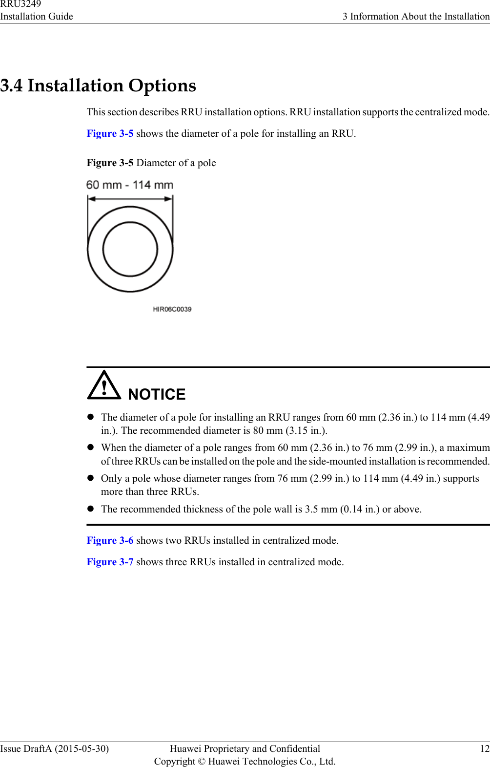
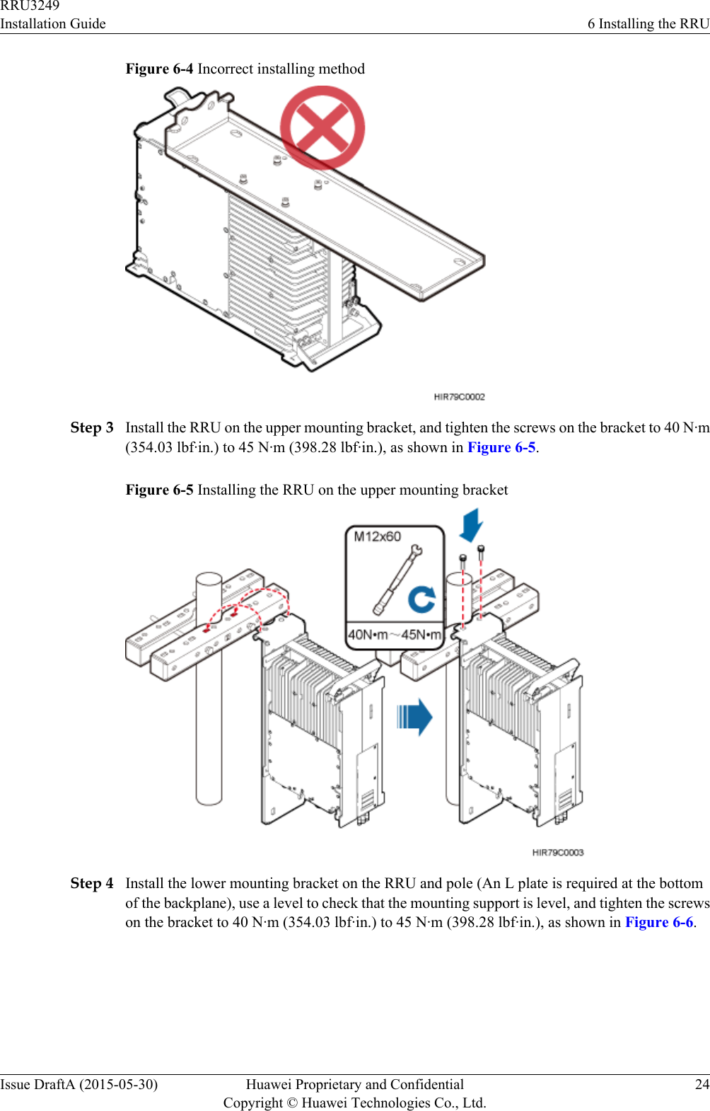
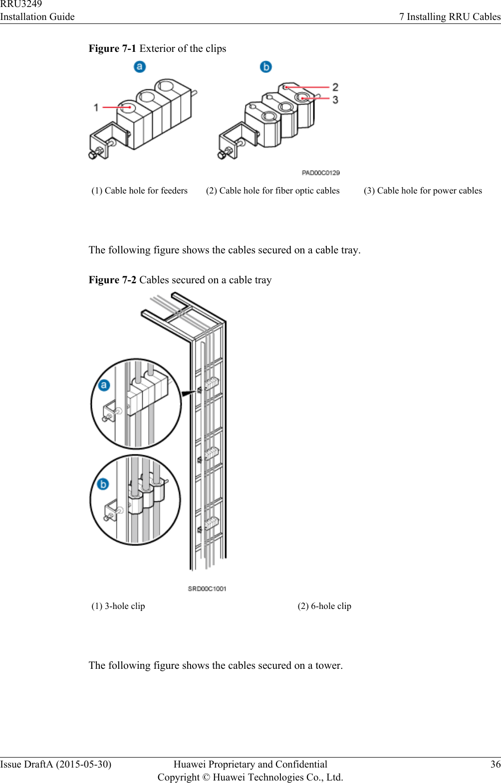
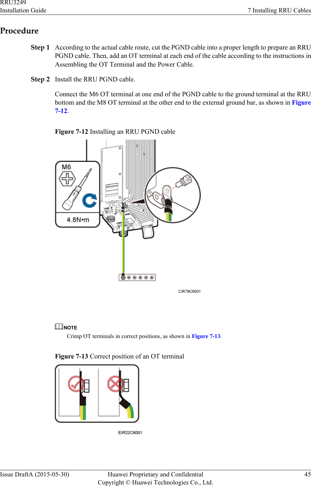
![Symbol DescriptionCalls attention to important information, best practices andtips.NOTE is used to address information not related to personalinjury, equipment damage, and environment deterioration. General ConventionsThe general conventions that may be found in this document are defined as follows.Convention DescriptionTimes New Roman Normal paragraphs are in Times New Roman.Boldface Names of files, directories, folders, and users are inboldface. For example, log in as user root.Italic Book titles are in italics.Courier New Examples of information displayed on the screen are inCourier New. Command ConventionsThe command conventions that may be found in this document are defined as follows.Convention DescriptionBoldface The keywords of a command line are in boldface.Italic Command arguments are in italics.[ ] Items (keywords or arguments) in brackets [ ] are optional.{ x | y | ... } Optional items are grouped in braces and separated byvertical bars. One item is selected.[ x | y | ... ] Optional items are grouped in brackets and separated byvertical bars. One item is selected or no item is selected.{ x | y | ... }*Optional items are grouped in braces and separated byvertical bars. A minimum of one item or a maximum of allitems can be selected.[ x | y | ... ]*Optional items are grouped in brackets and separated byvertical bars. Several items or no item can be selected. GUI ConventionsRRU3249Installation Guide About This DocumentIssue DraftA (2015-05-30) Huawei Proprietary and ConfidentialCopyright © Huawei Technologies Co., Ltd.iv](https://usermanual.wiki/Huawei-Technologies/RRU3249.UserManual-Installation-pdf/User-Guide-2634414-Page-5.png)

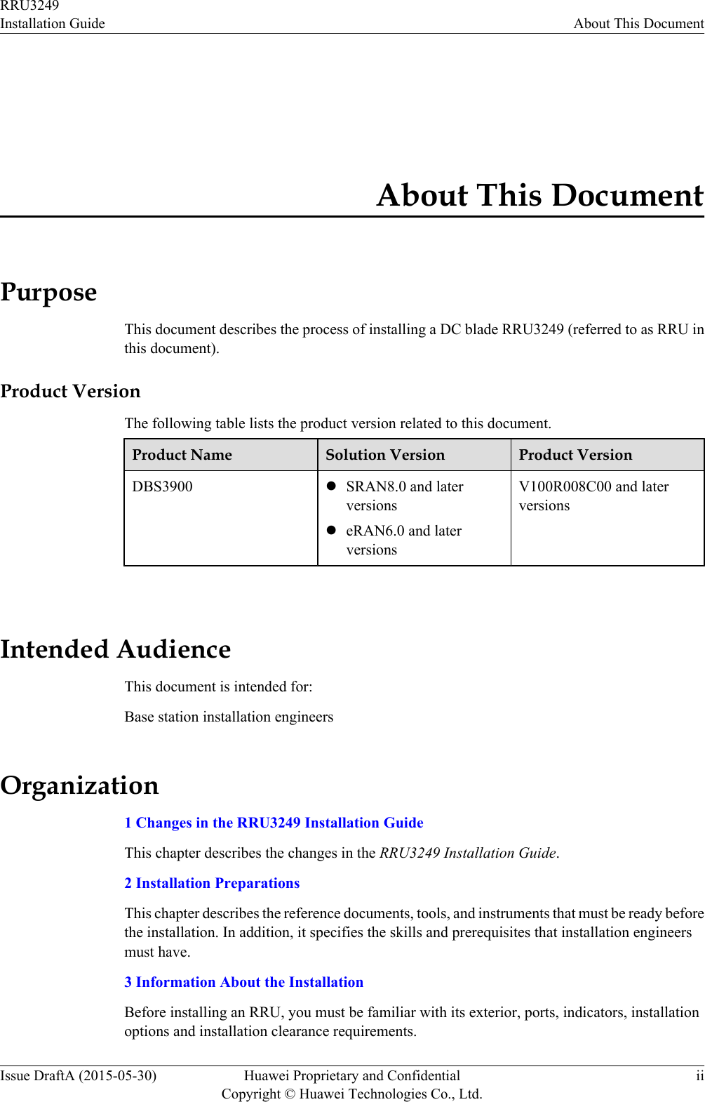
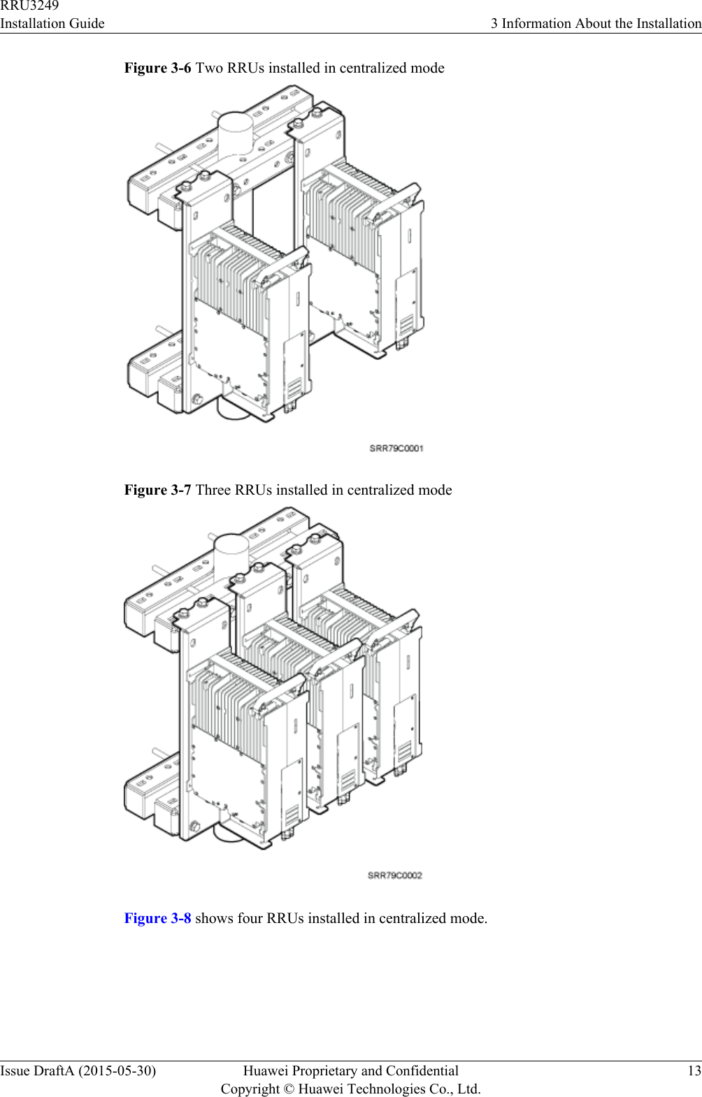
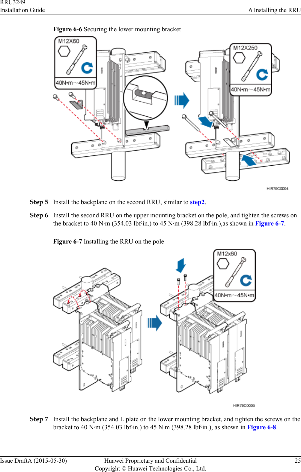
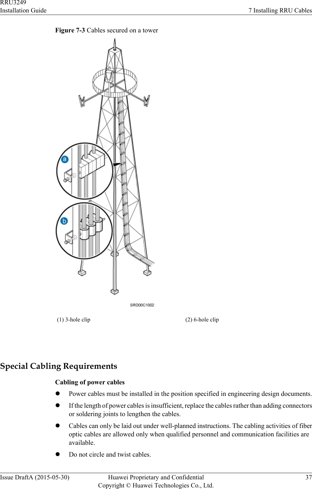
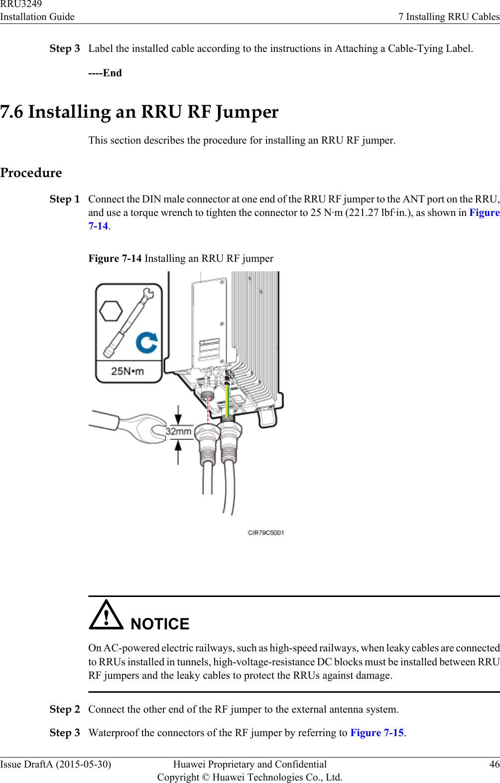
![Utility knife Cable cutter Adjustable wrench (size ≥ 32mm [1.26 in.])Torque wrenchSize: 18 mm (0.71 in.) and 32mm (1.26 in.)Combination wrenchSize: 18 mm (0.71 in.) and 32mm (1.26 in.)Level Torque screwdriver5 mm5 mm(M3 to M6)(M3 to M6)Torque socketMultimeter Marker (diameter ≤ 10 mm[0.39 in.])Measuring tapeInner hexagon wrench5 mmFixed pulley Lifting slingHydraulic pliers - - RRU3249Installation Guide 2 Installation PreparationsIssue DraftA (2015-05-30) Huawei Proprietary and ConfidentialCopyright © Huawei Technologies Co., Ltd.4](https://usermanual.wiki/Huawei-Technologies/RRU3249.UserManual-Installation-pdf/User-Guide-2634414-Page-12.png)
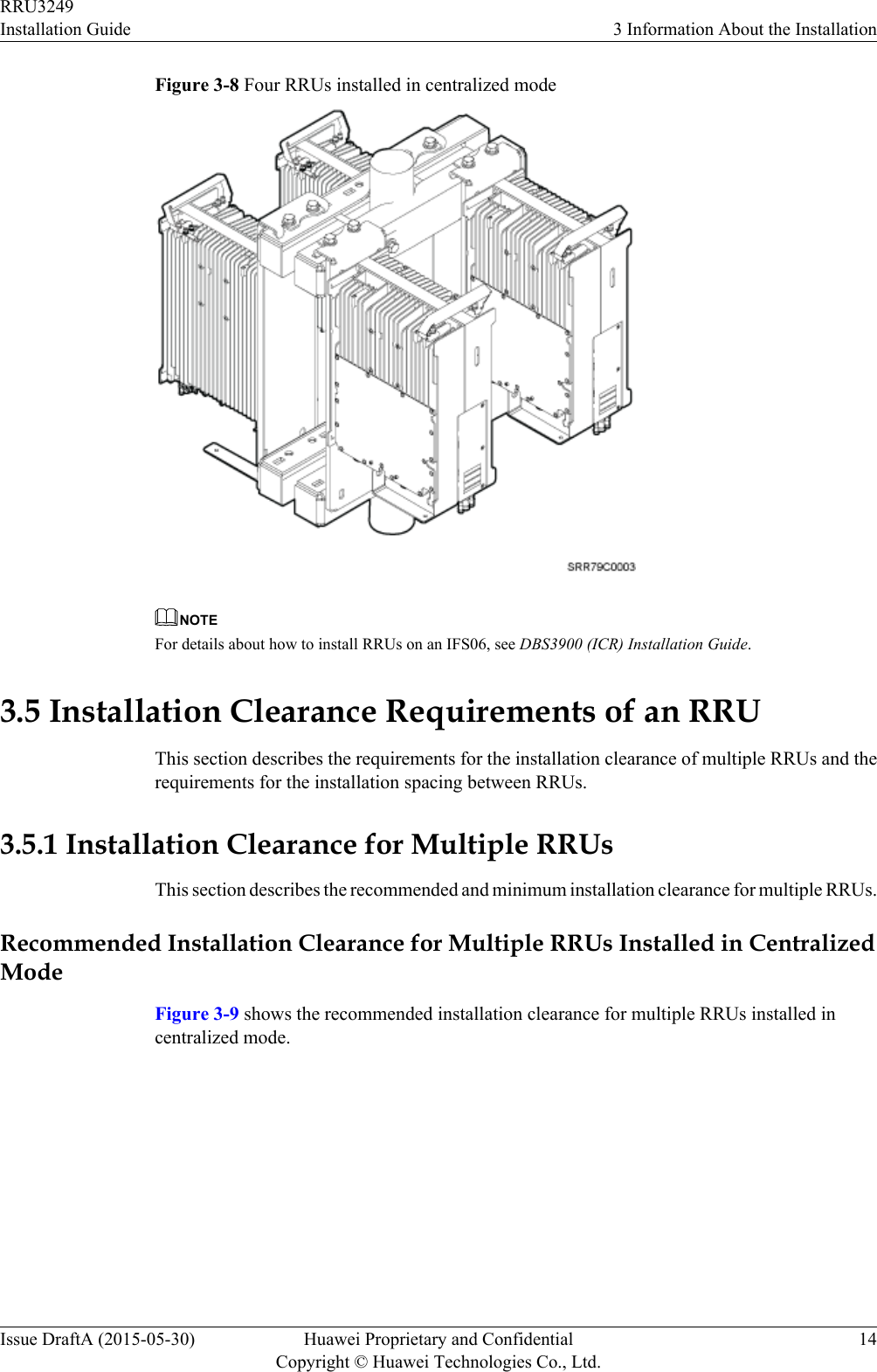
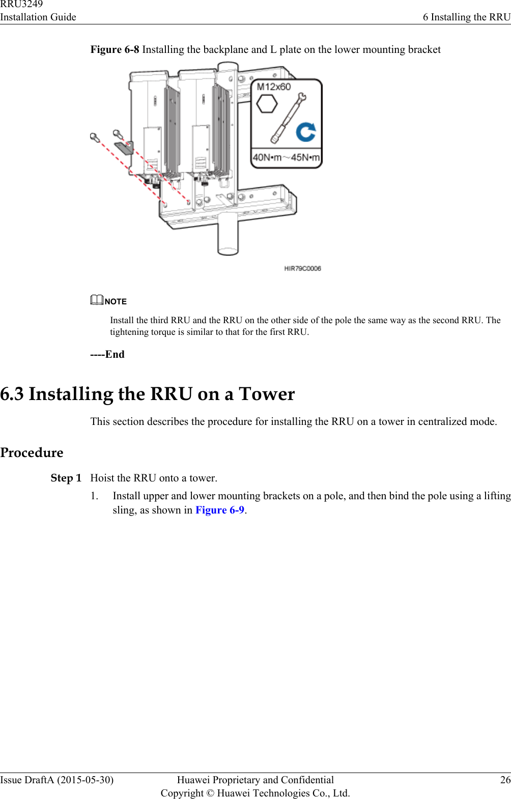
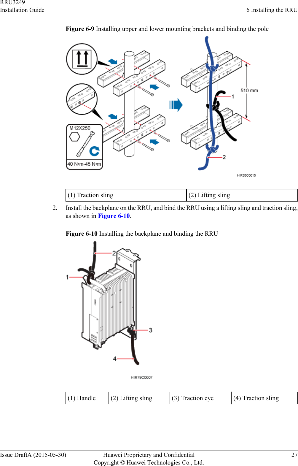

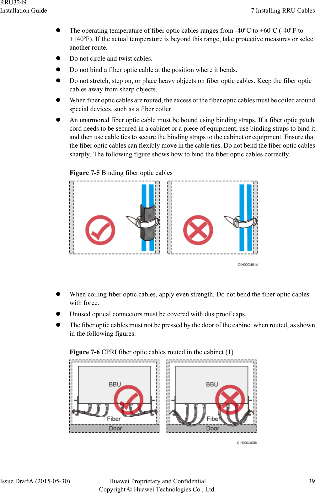
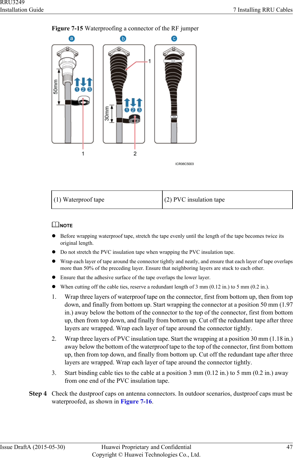
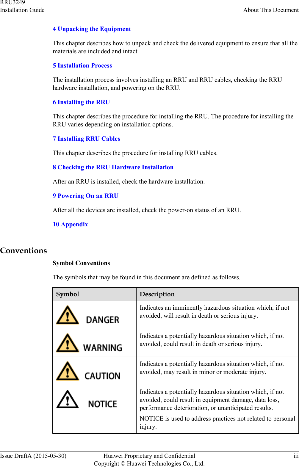
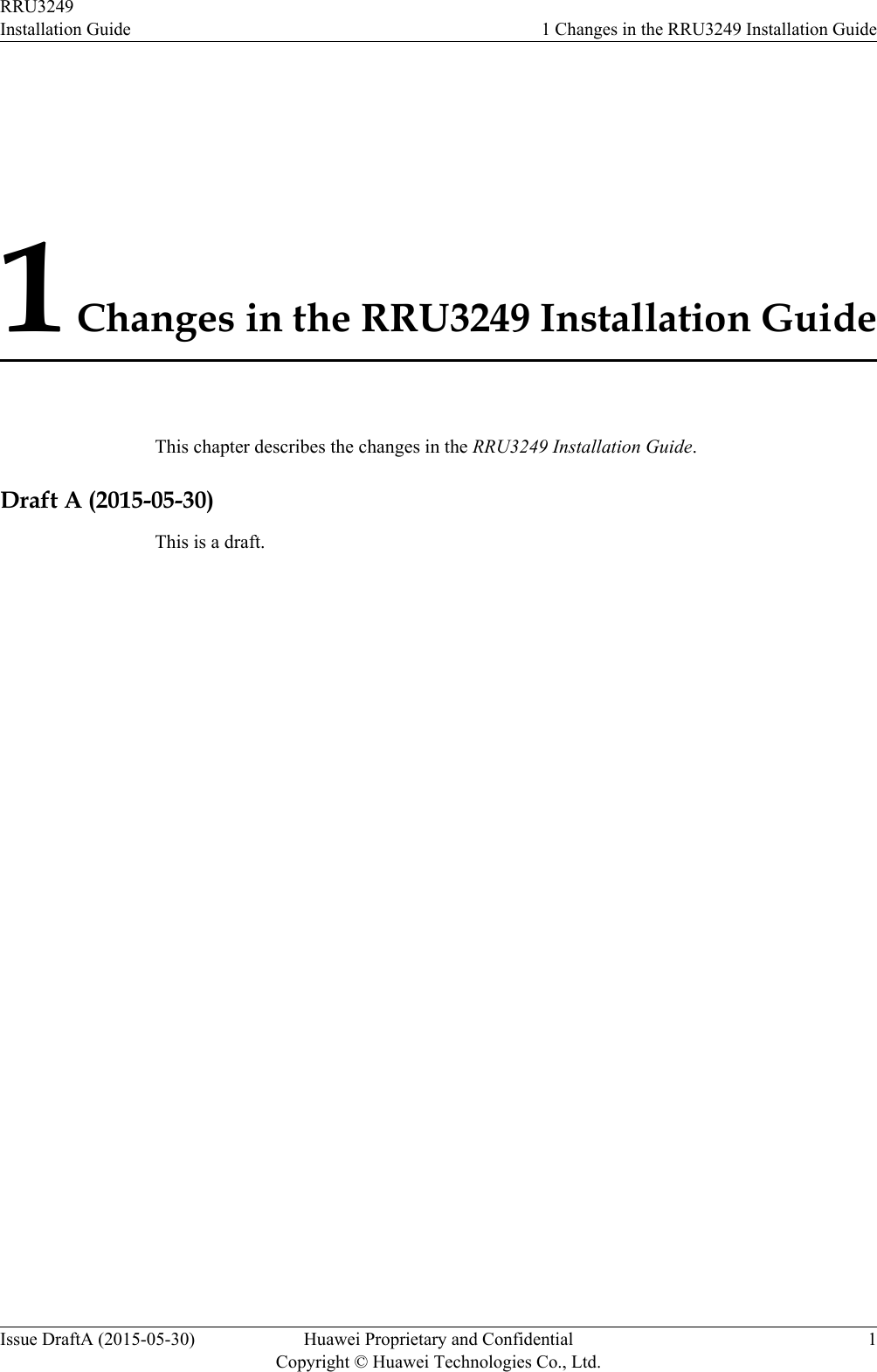
![Step 5 Strip the specified length of the sheath off the power cable to expose the intact shield layer, asshown in Figure 10-8.Figure 10-8 Stripping the sheath off the power cable NOTICEEach core wire is exposed outside the tool-less female connector (pressfit type) for 1.5 mm(0.059 [in.]), as shown in Figure 10-9.Figure 10-9 Inserting core wires into the tool-less female connector (pressfit type)----EndRRU3249Installation Guide 10 AppendixIssue DraftA (2015-05-30) Huawei Proprietary and ConfidentialCopyright © Huawei Technologies Co., Ltd.69](https://usermanual.wiki/Huawei-Technologies/RRU3249.UserManual-Installation-pdf/User-Guide-2634414-Page-77.png)