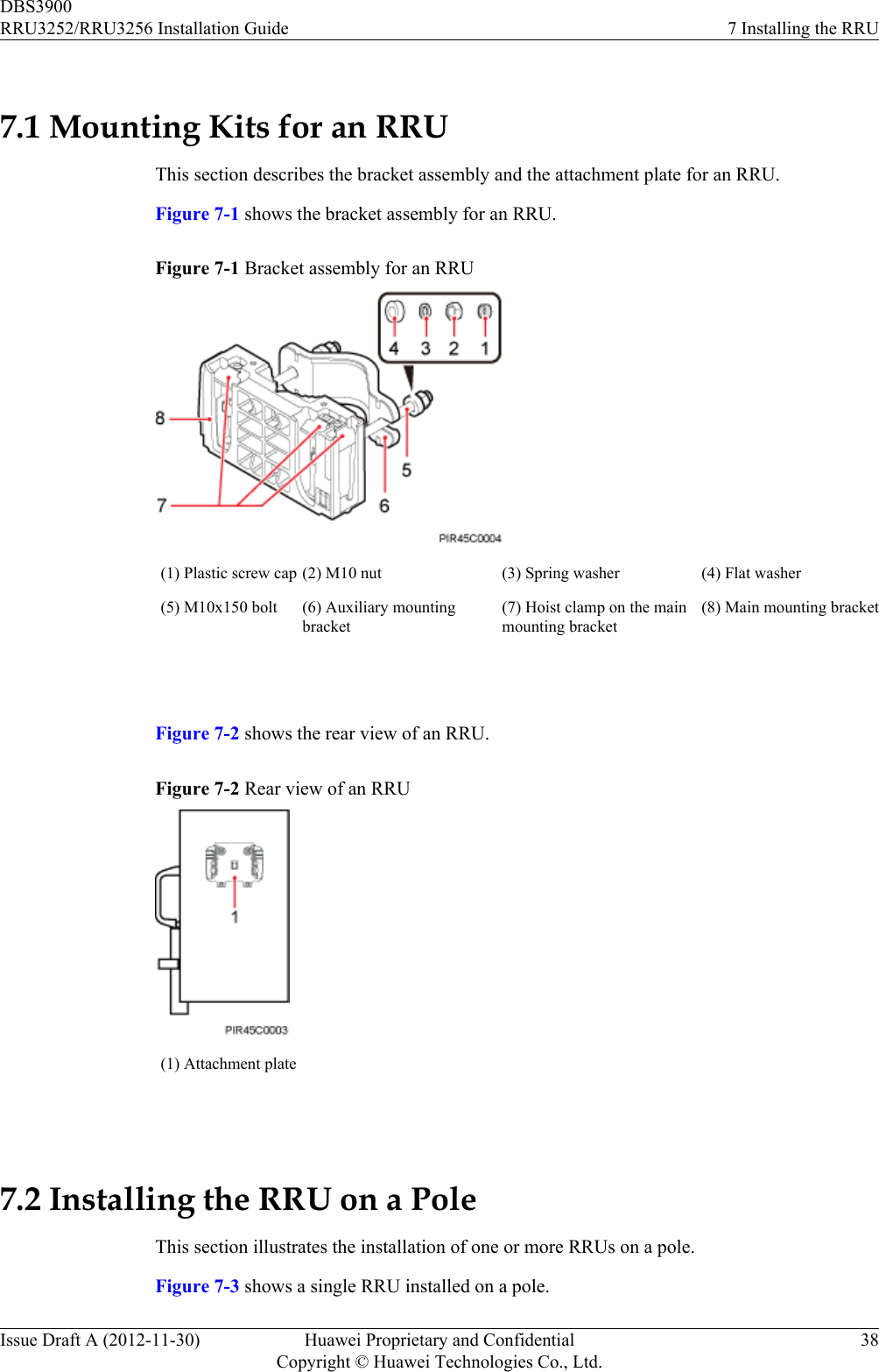
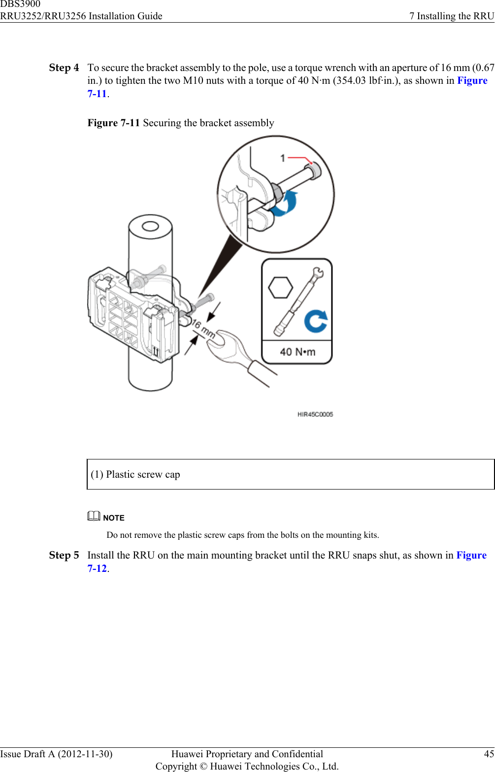
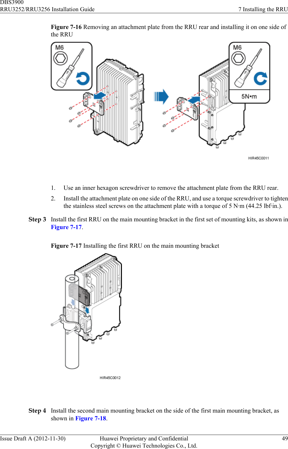
Huawei Technologies RRU3252B41 RRU3252 Remote Radio Unit User Manual RRU3252 RRU3256 Installation Guide
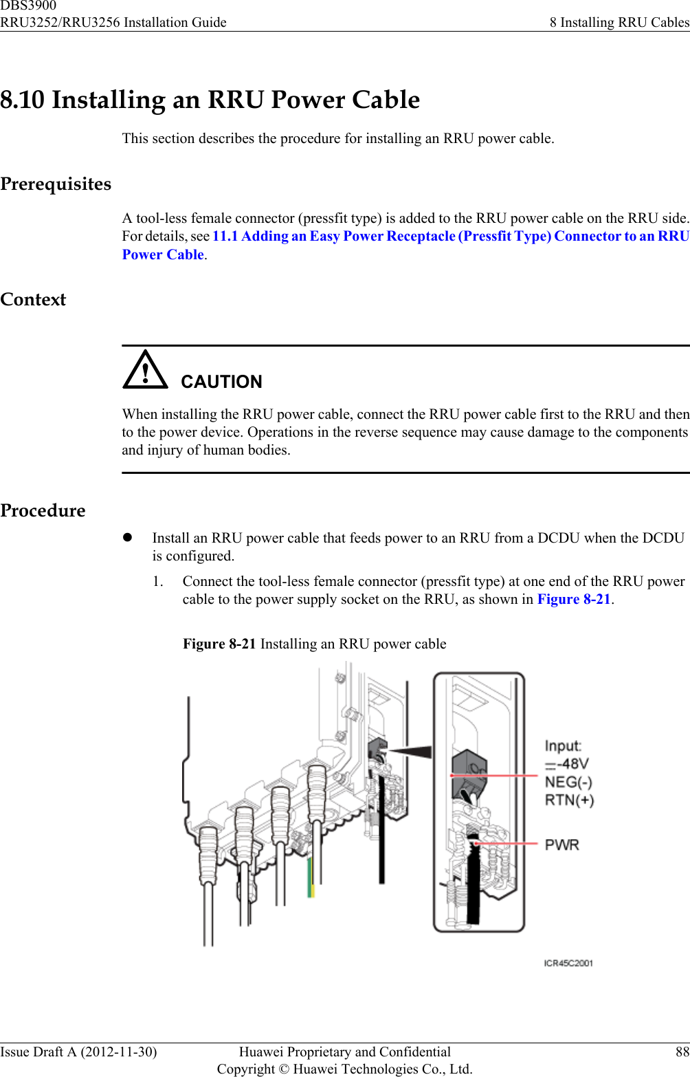
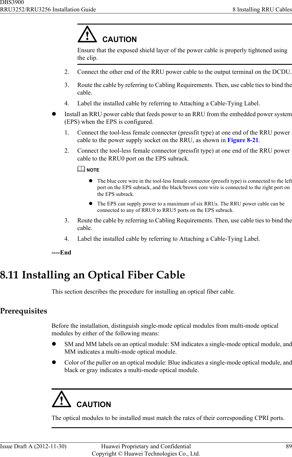
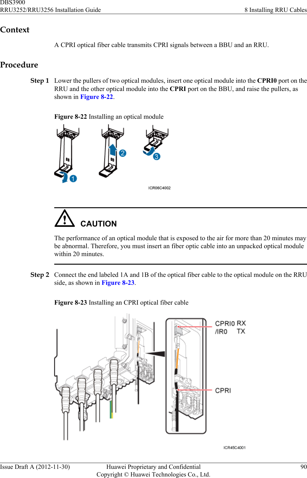
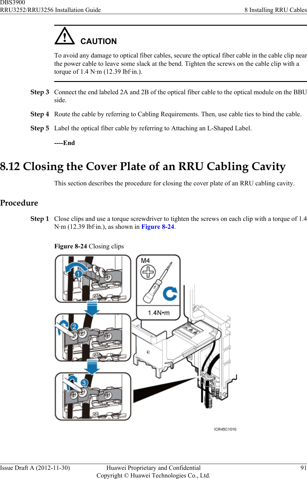
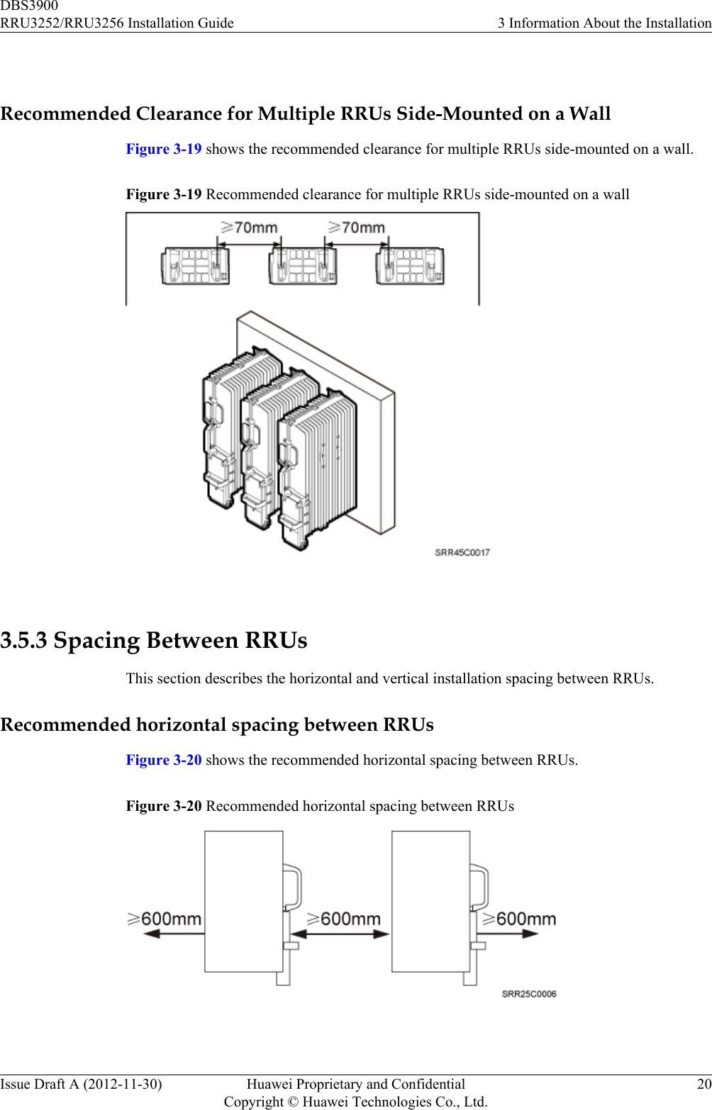
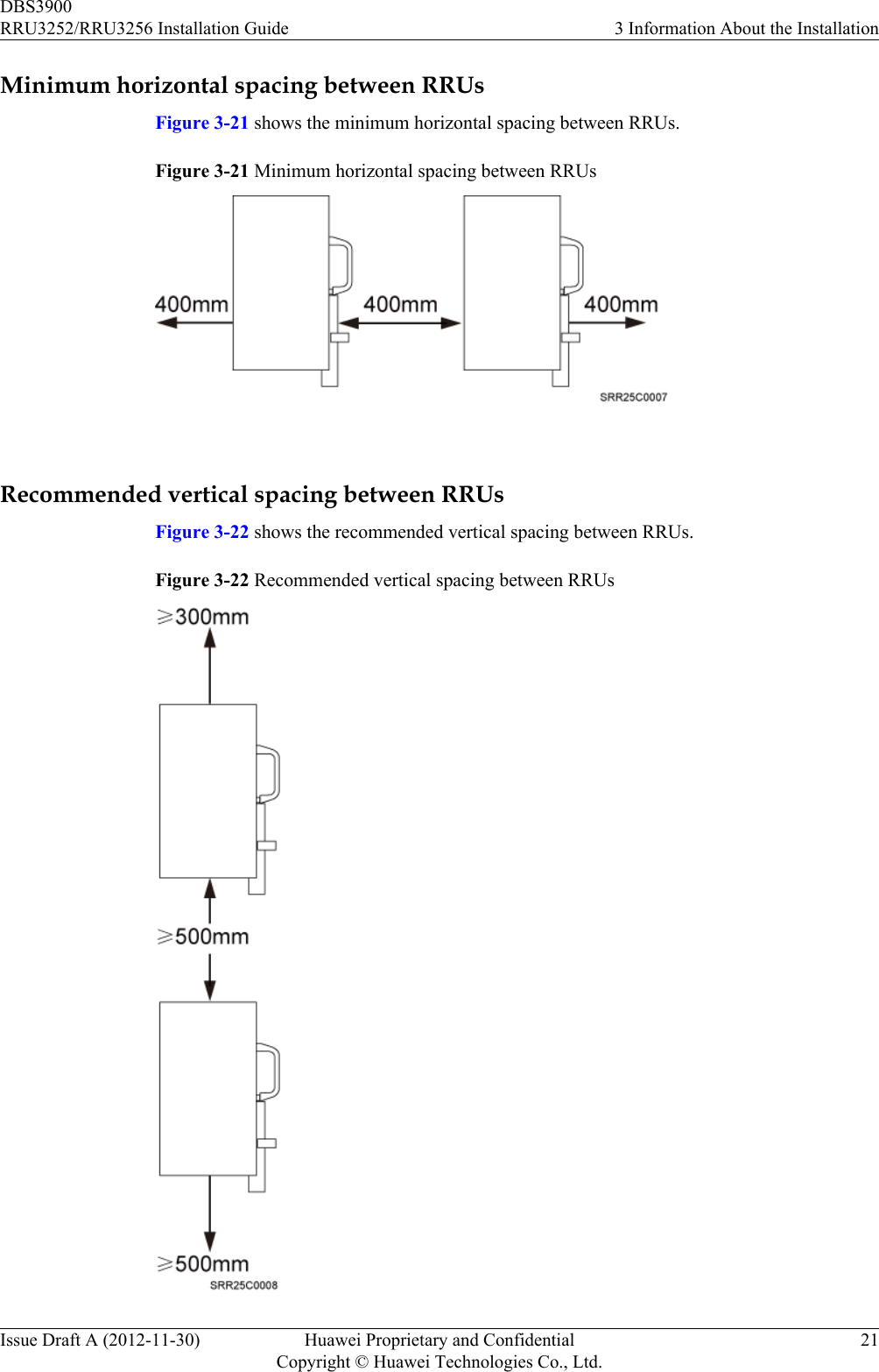
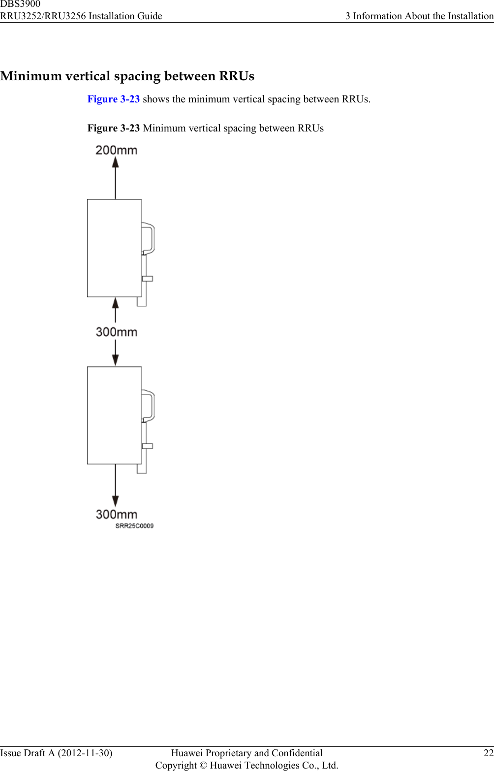
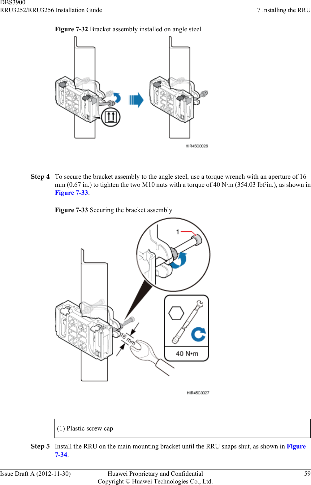
Huawei Technologies Co.,Ltd RRU3252 Remote Radio Unit RRU3252 RRU3256 Installation Guide
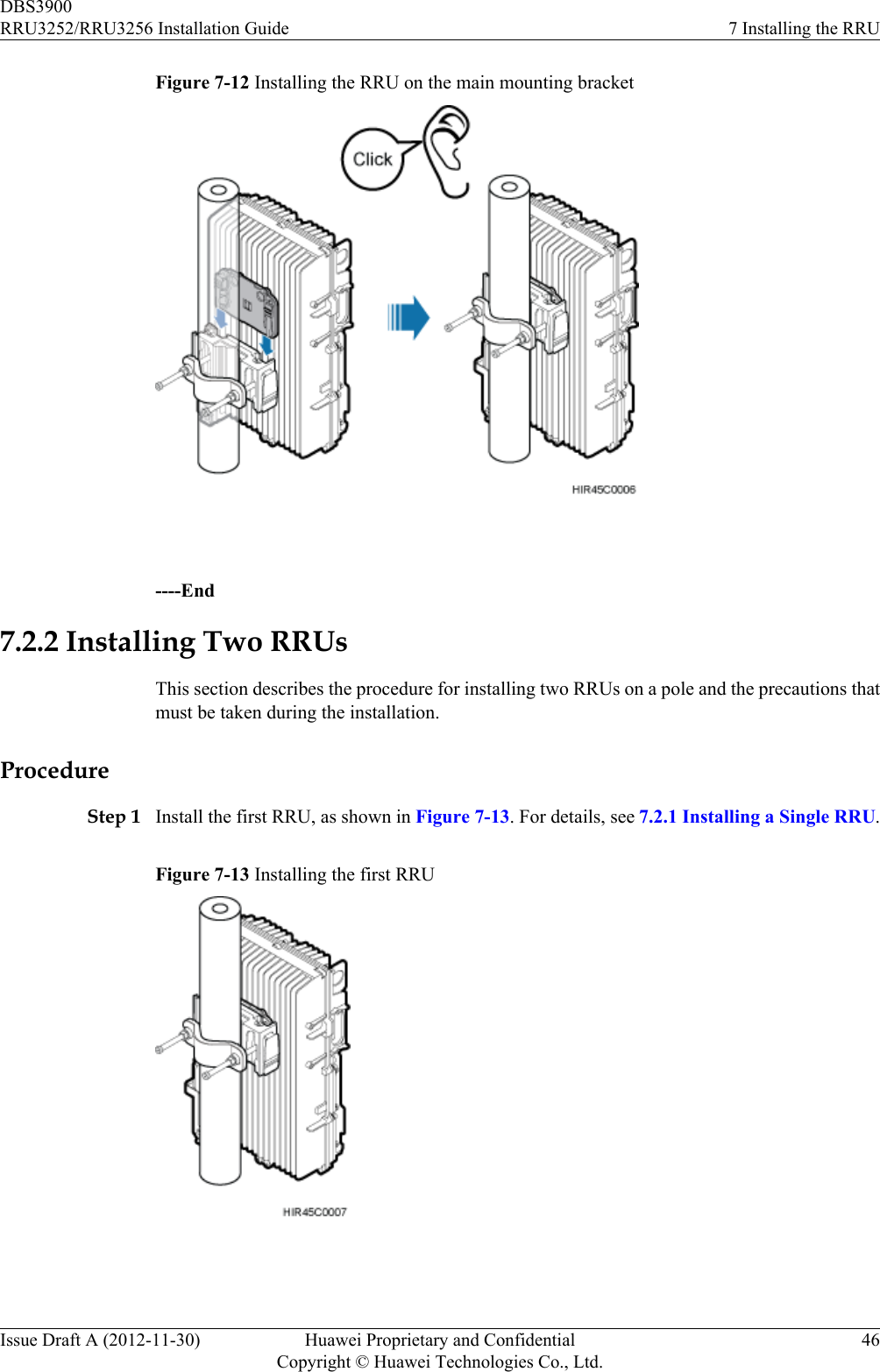
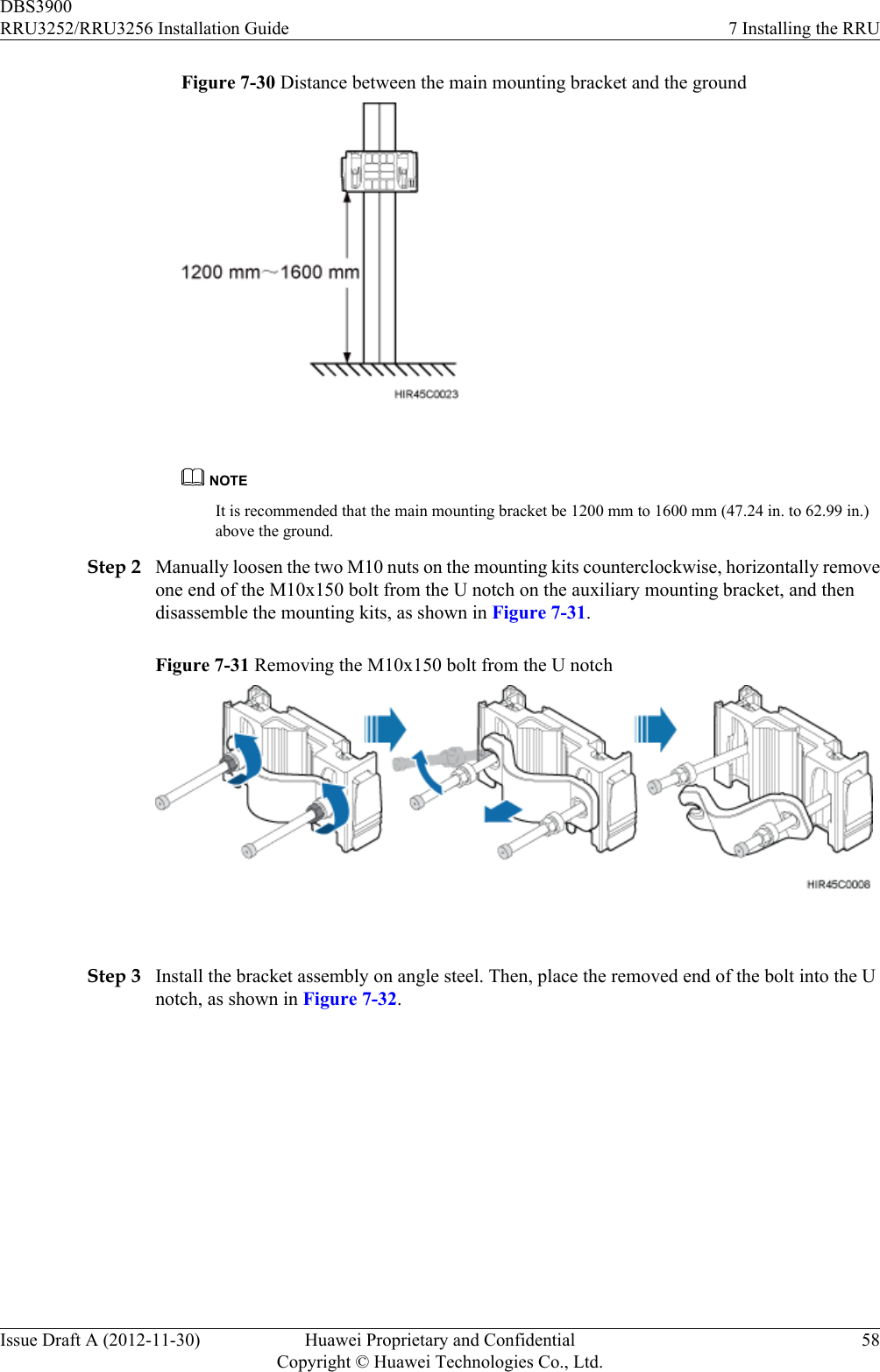
Contents
- 1. Manual_RRU3252 Compliance and Safety Manual_20130307_023605.pdf
- 2. Manual_RRU3252_ Hardware Maintenance Guide-EN.pdf
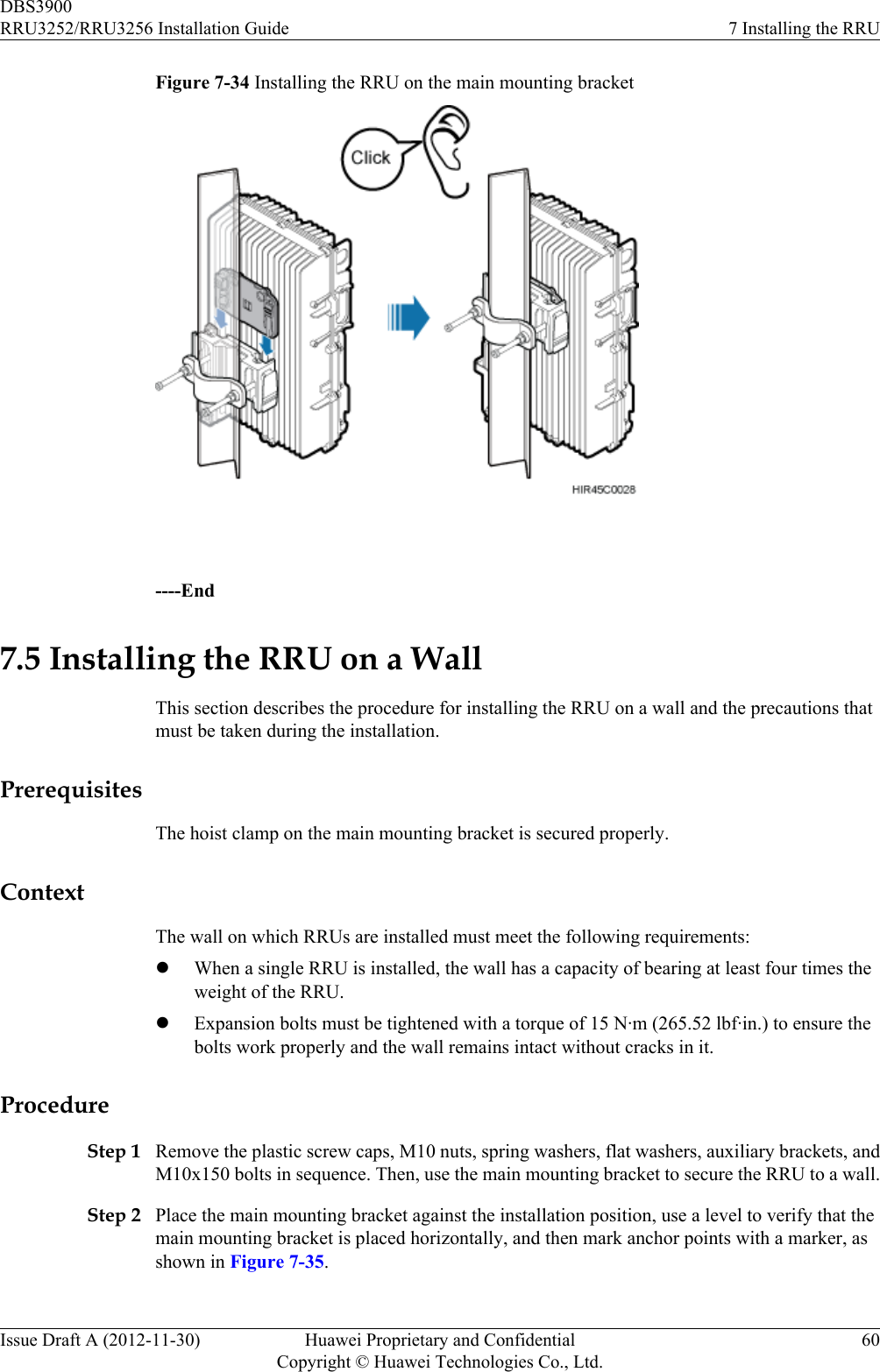
- 3. Manual_RRU3252_Installation Guide-EN.pdf
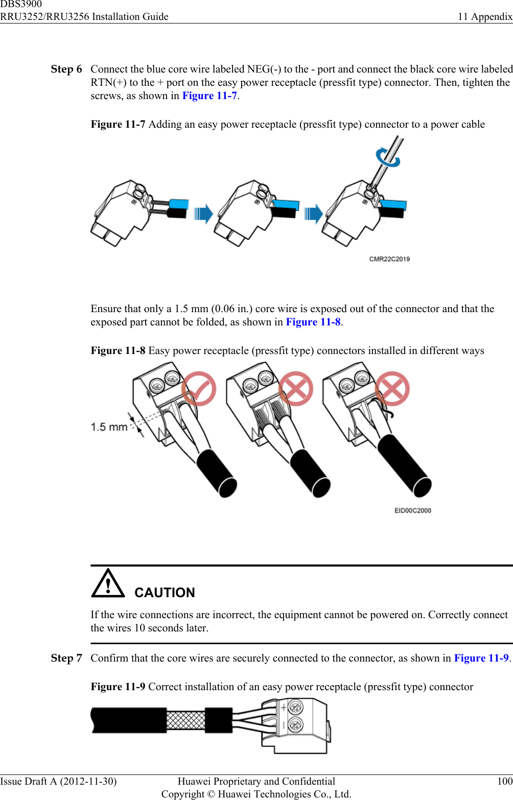
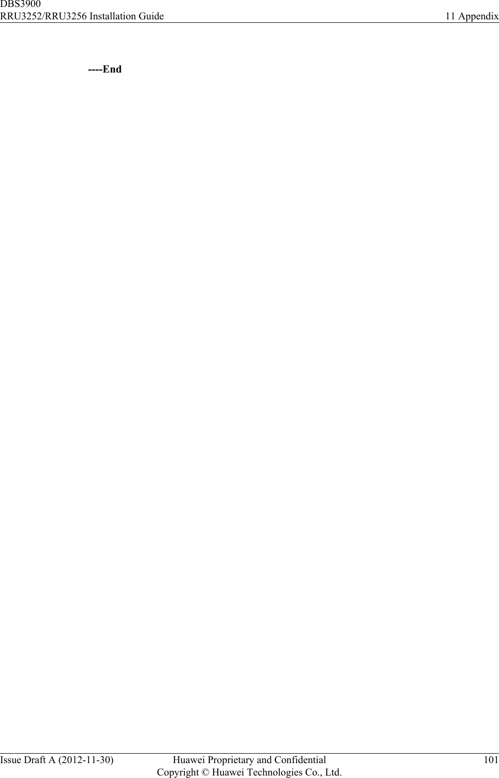
Manual_RRU3252_Installation Guide-EN.pdf
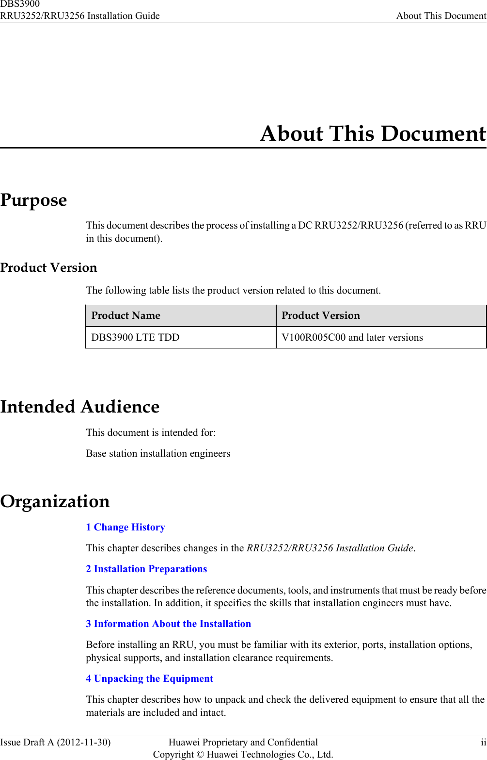
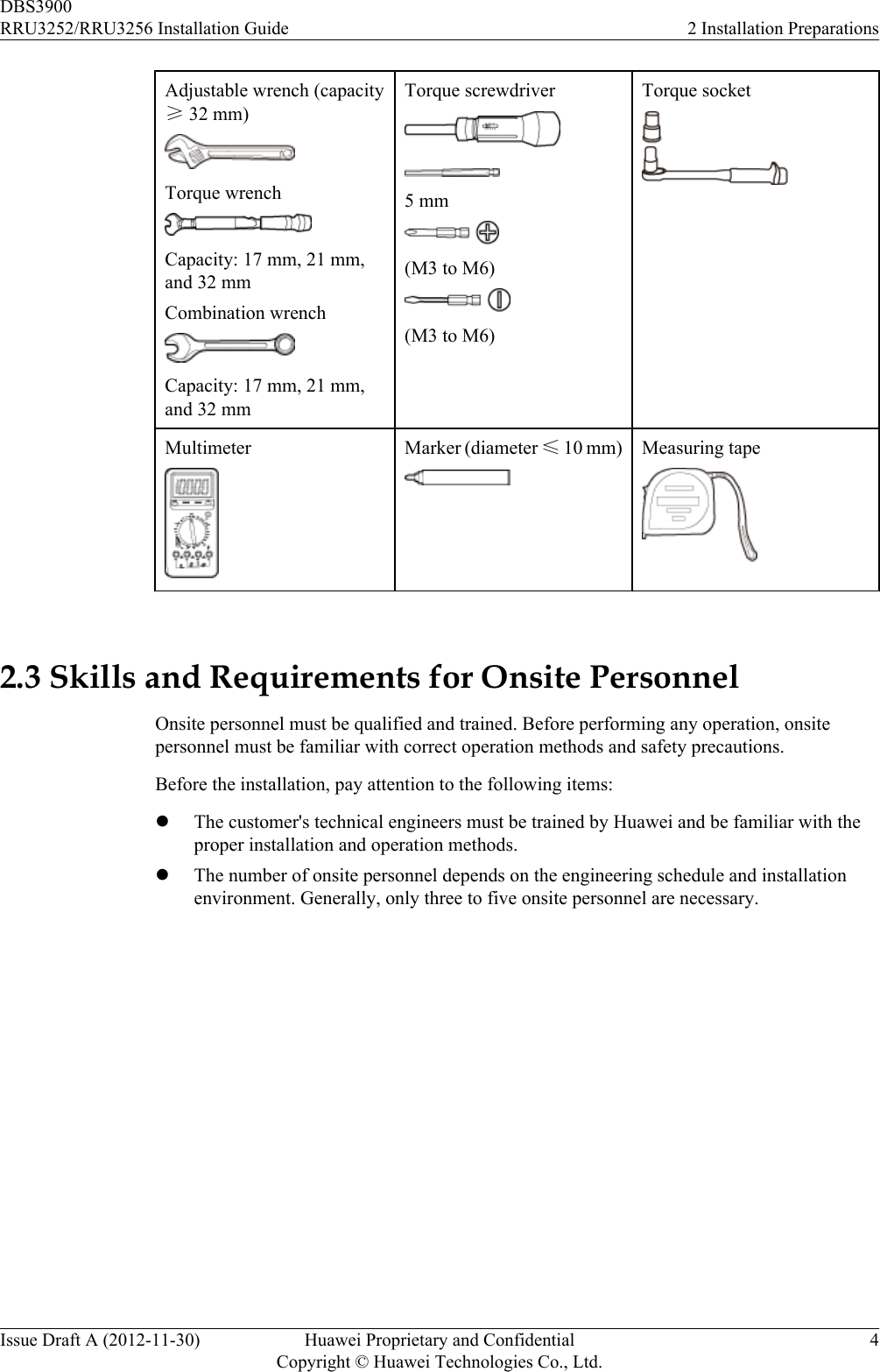
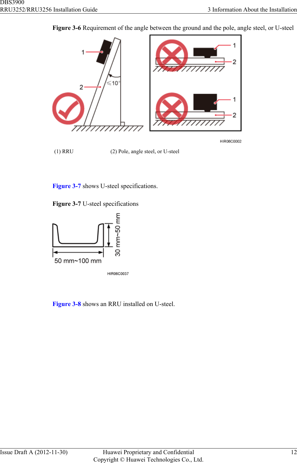
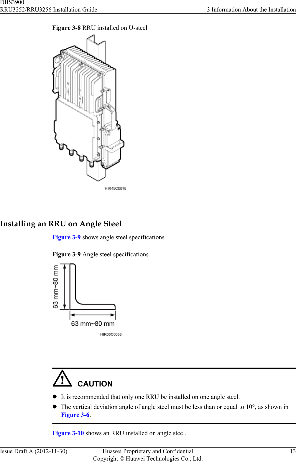
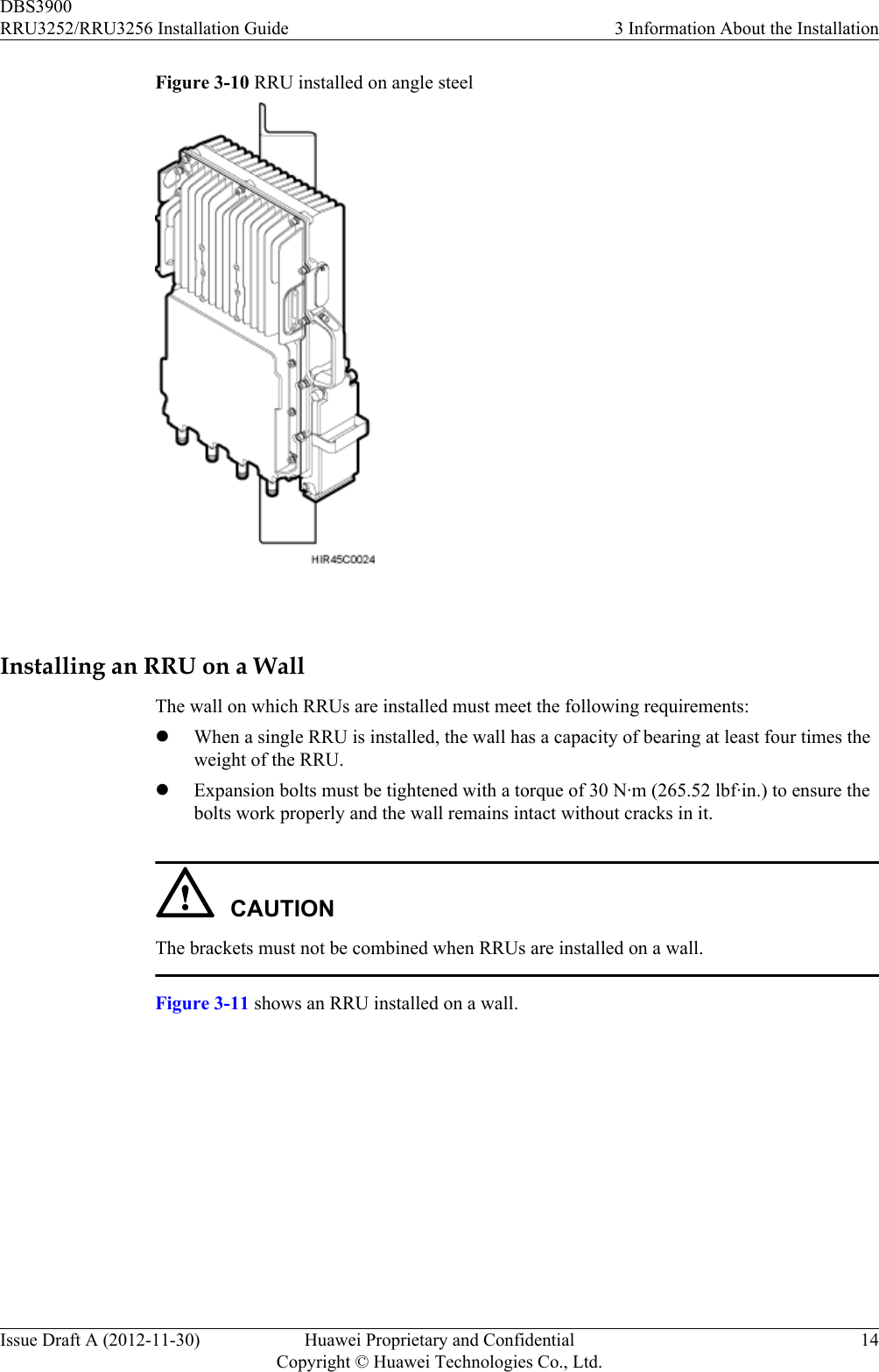
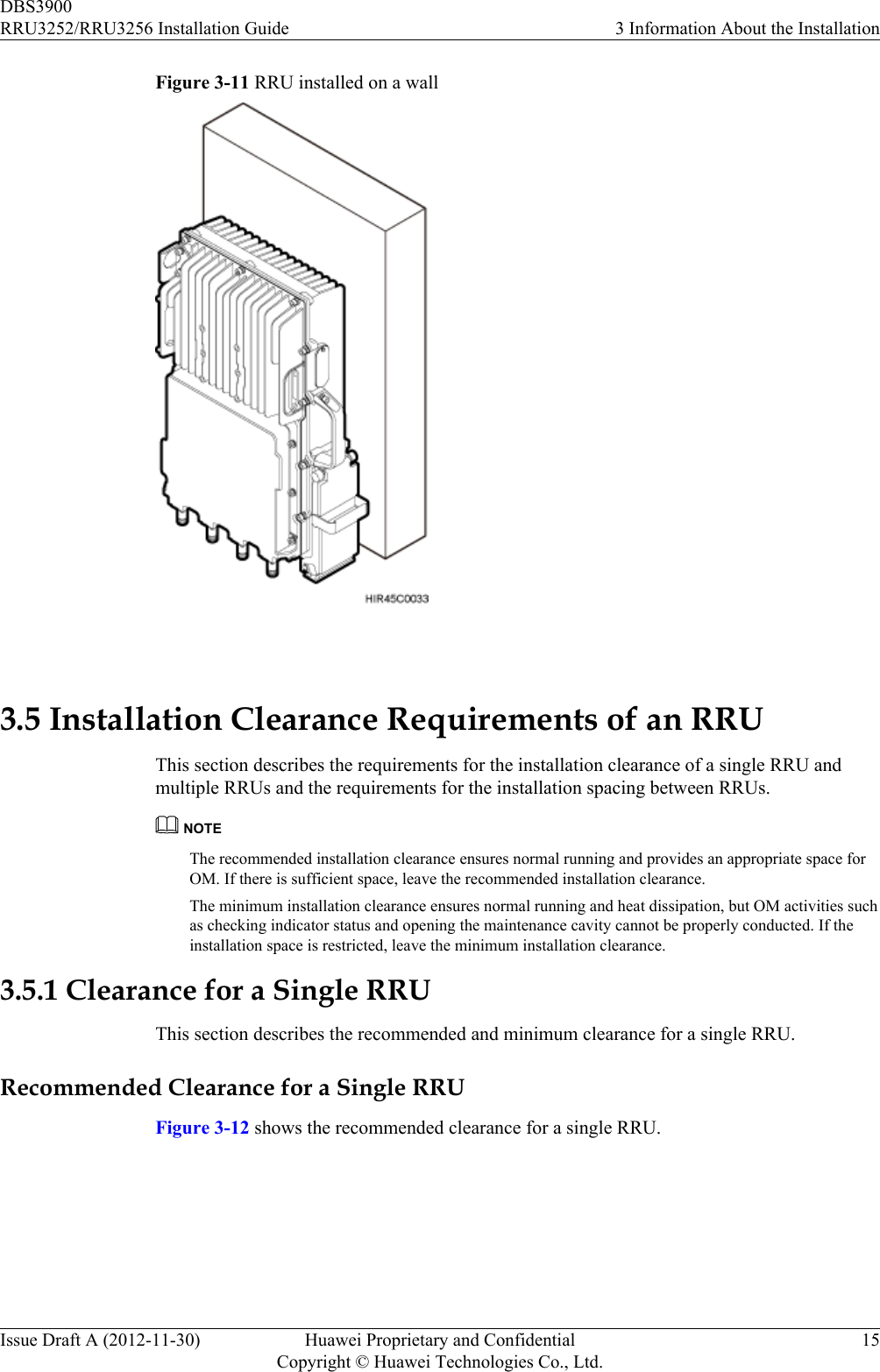
![General ConventionsThe general conventions that may be found in this document are defined as follows.Convention DescriptionTimes New Roman Normal paragraphs are in Times New Roman.Boldface Names of files, directories, folders, and users are inboldface. For example, log in as user root.Italic Book titles are in italics.Courier New Examples of information displayed on the screen are inCourier New. Command ConventionsThe command conventions that may be found in this document are defined as follows.Convention DescriptionBoldface The keywords of a command line are in boldface.Italic Command arguments are in italics.[ ] Items (keywords or arguments) in brackets [ ] are optional.{ x | y | ... } Optional items are grouped in braces and separated byvertical bars. One item is selected.[ x | y | ... ] Optional items are grouped in brackets and separated byvertical bars. One item is selected or no item is selected.{ x | y | ... }*Optional items are grouped in braces and separated byvertical bars. A minimum of one item or a maximum of allitems can be selected.[ x | y | ... ]*Optional items are grouped in brackets and separated byvertical bars. Several items or no item can be selected. GUI ConventionsThe GUI conventions that may be found in this document are defined as follows.Convention DescriptionBoldface Buttons, menus, parameters, tabs, window, and dialog titlesare in boldface. For example, click OK.>Multi-level menus are in boldface and separated by the ">"signs. For example, choose File > Create > Folder. DBS3900RRU3252/RRU3256 Installation Guide About This DocumentIssue Draft A (2012-11-30) Huawei Proprietary and ConfidentialCopyright © Huawei Technologies Co., Ltd.iv](https://usermanual.wiki/Huawei-Technologies/RRU3252B41.Manual-RRU3252-Installation-Guide-EN-pdf/User-Guide-1922955-Page-5.png)
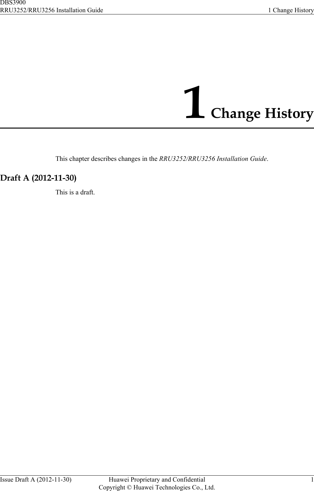
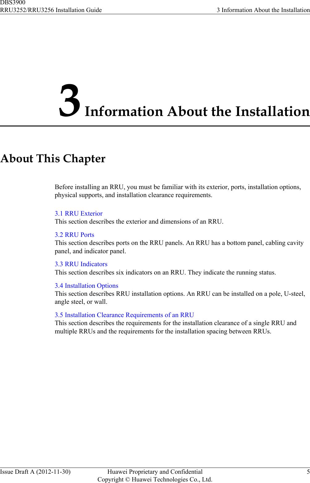
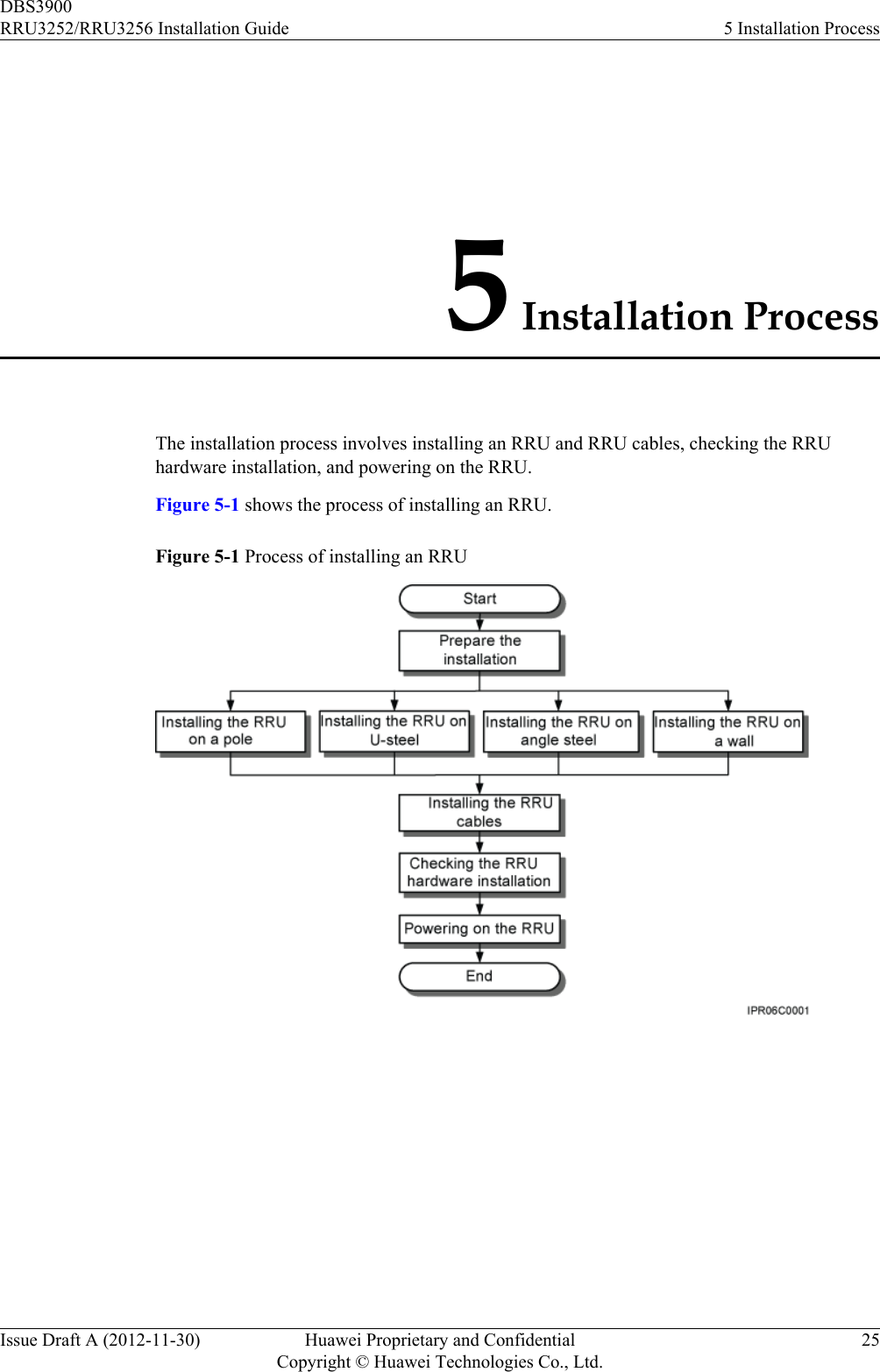
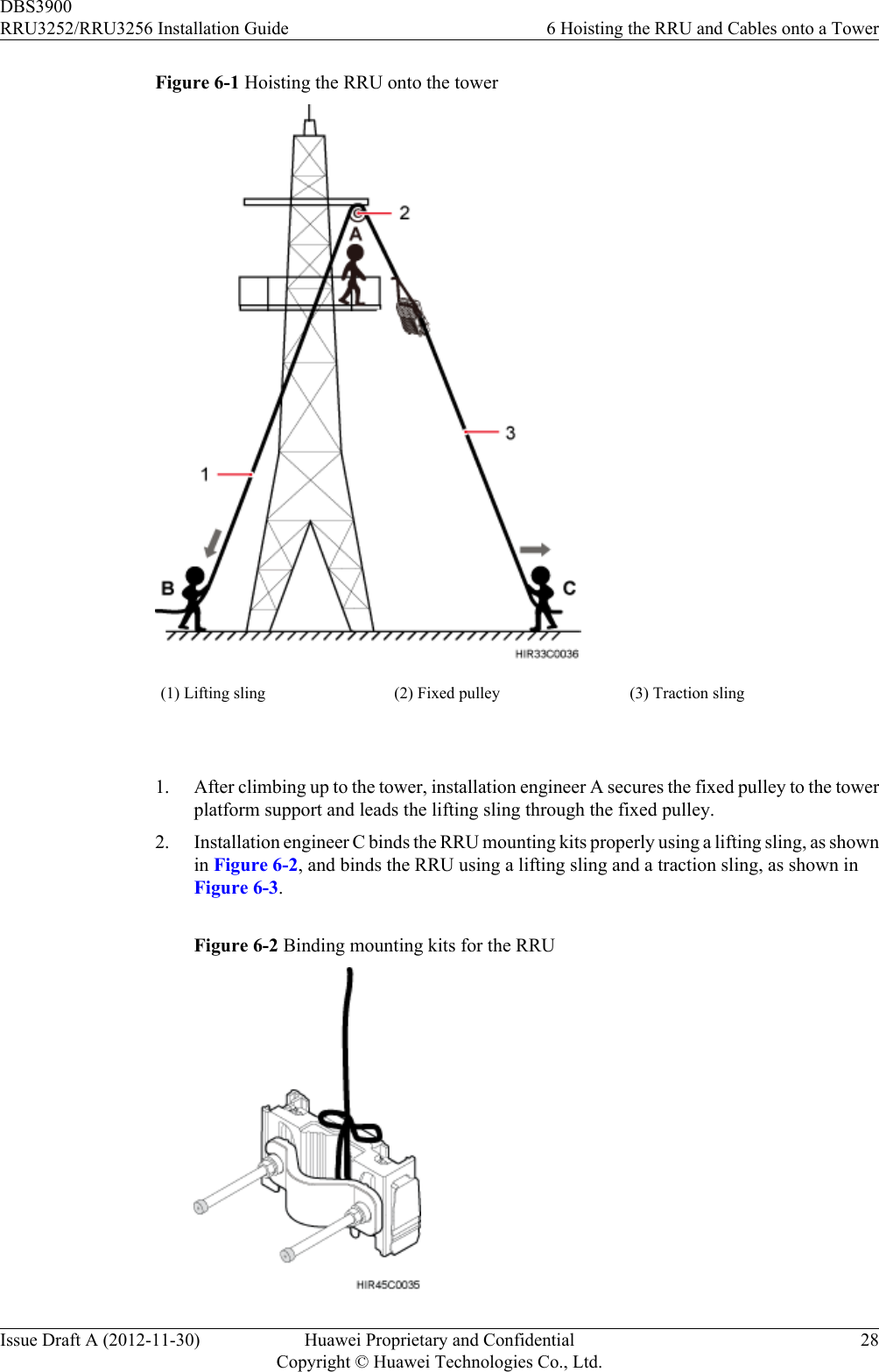
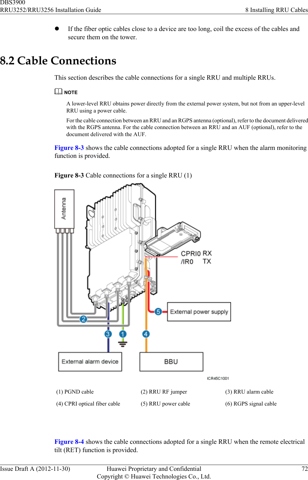
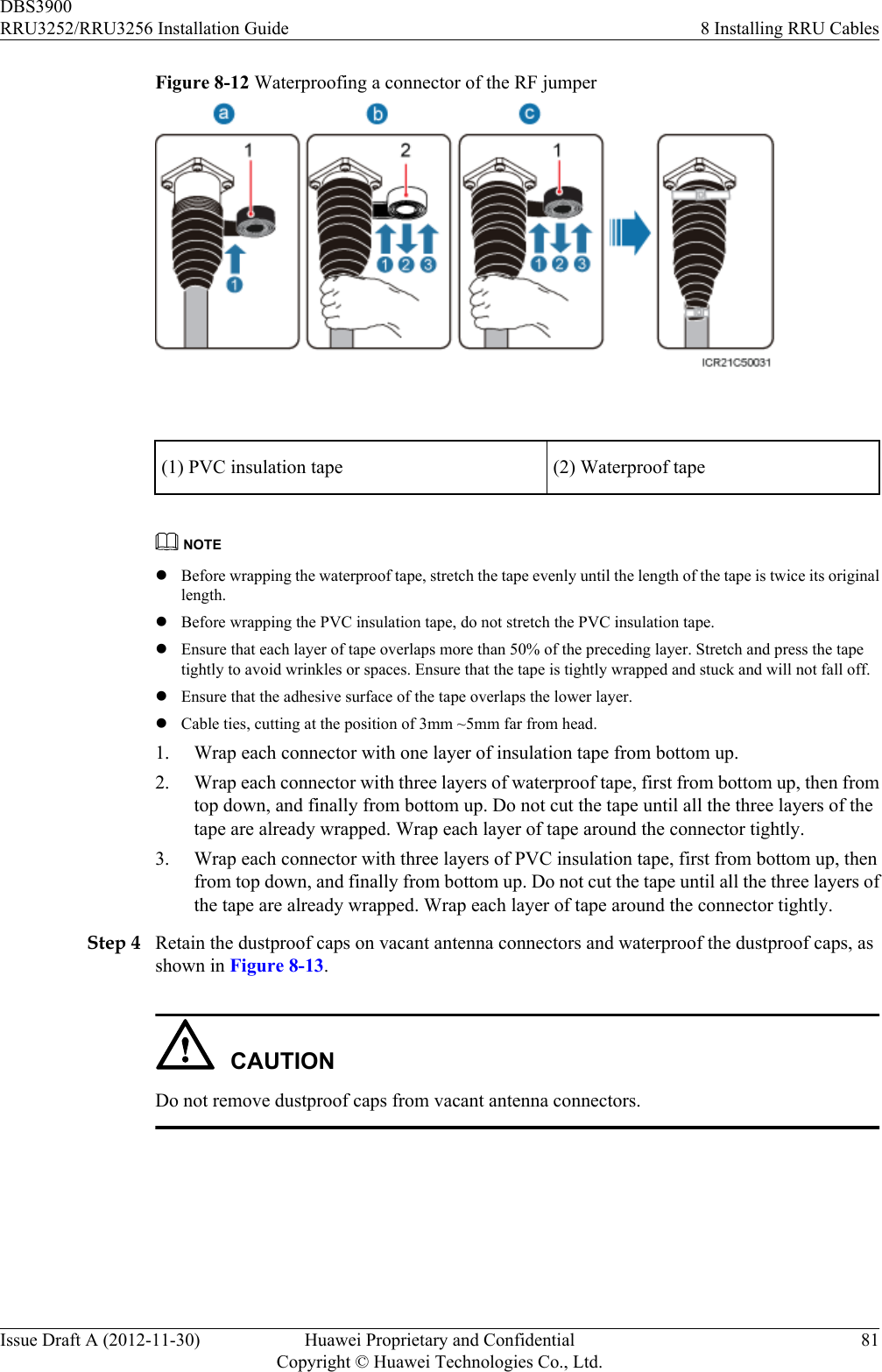
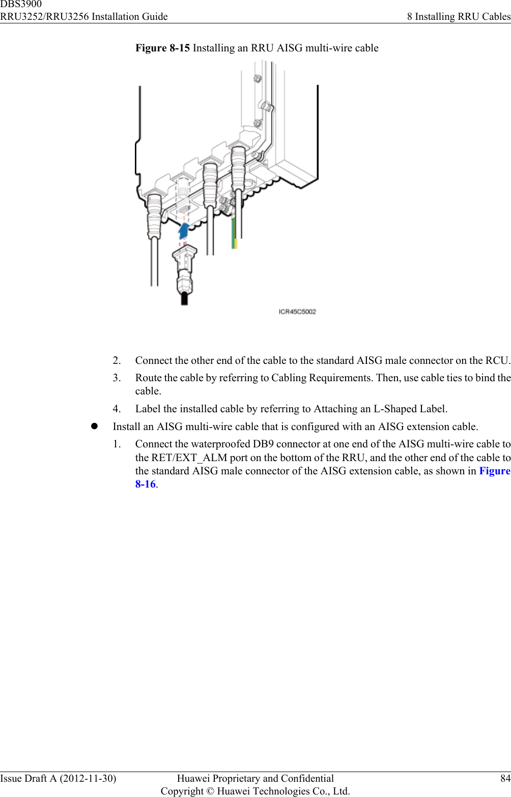
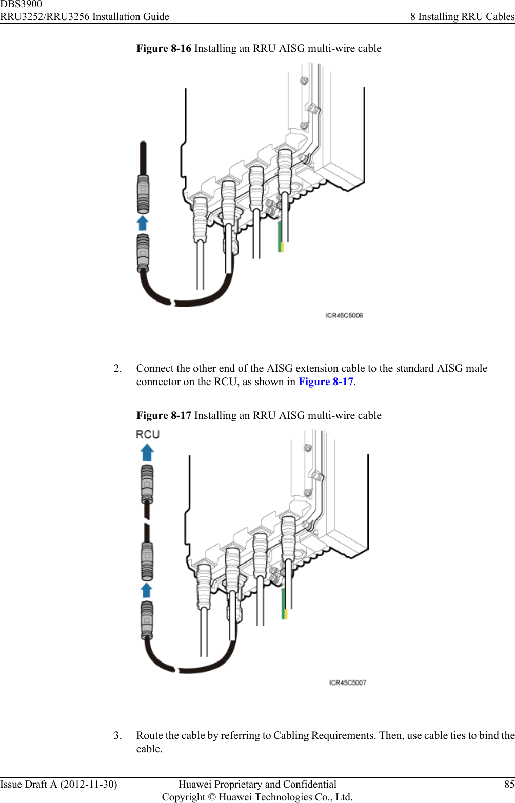
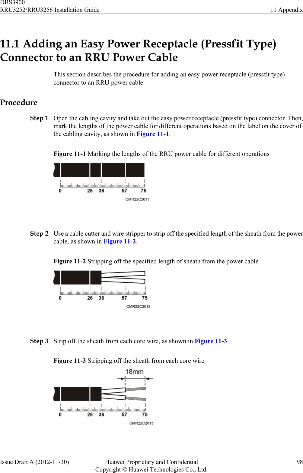
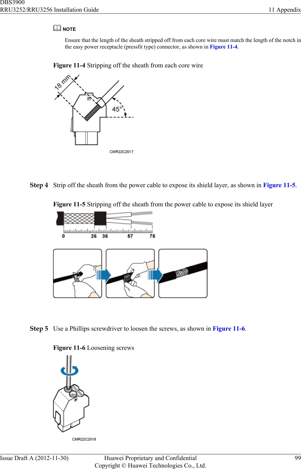
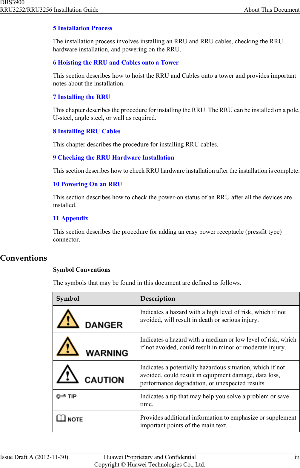
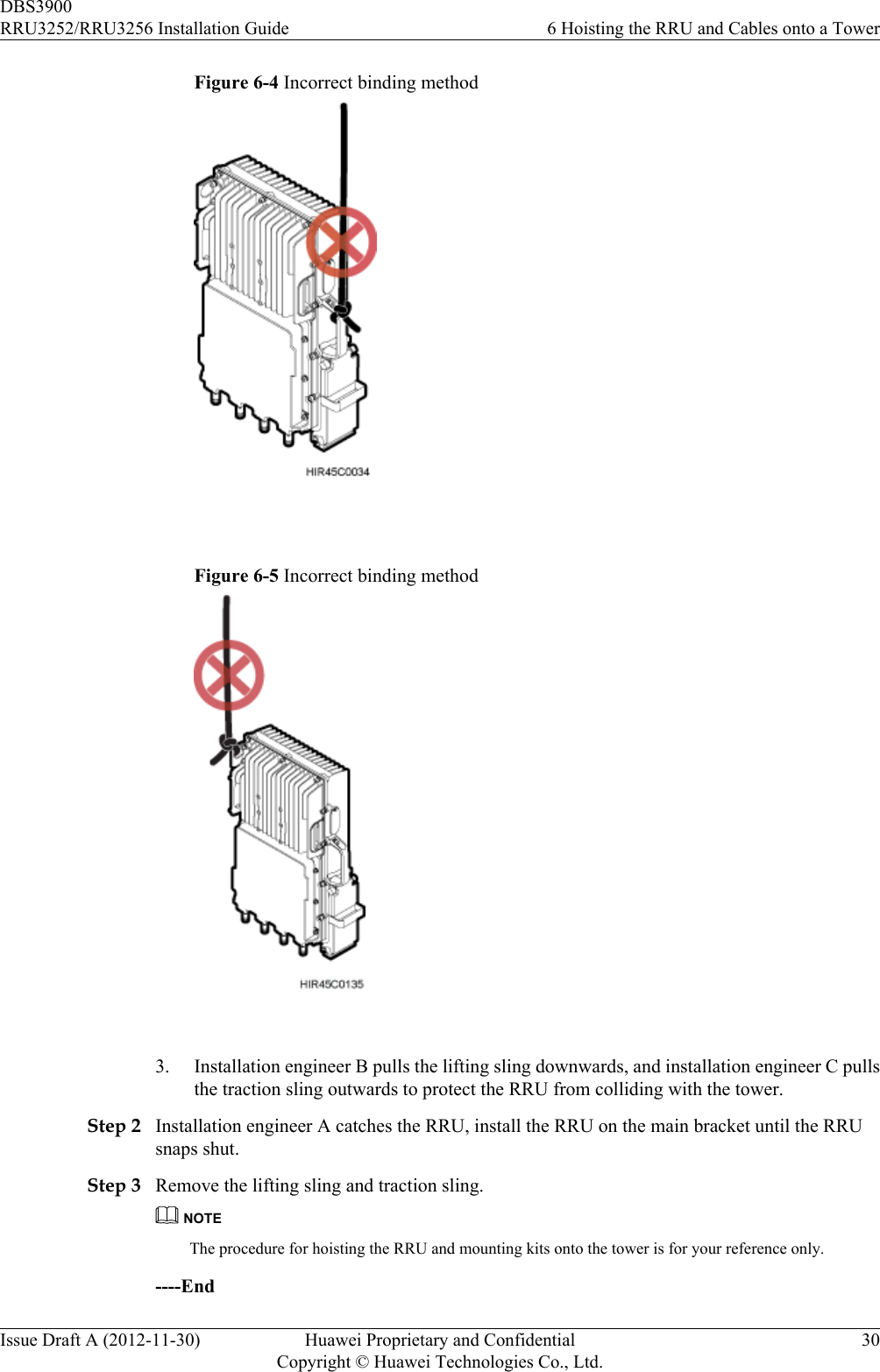
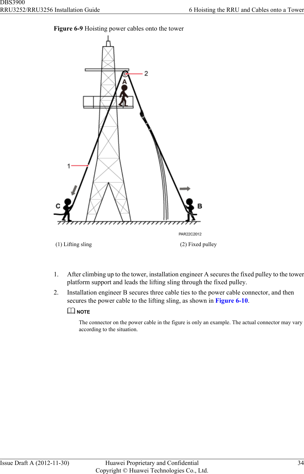
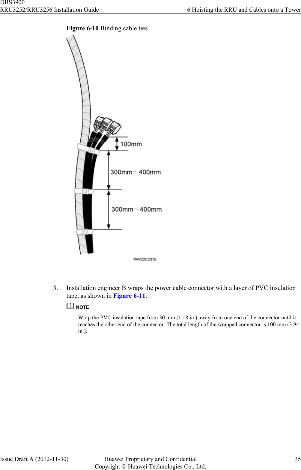
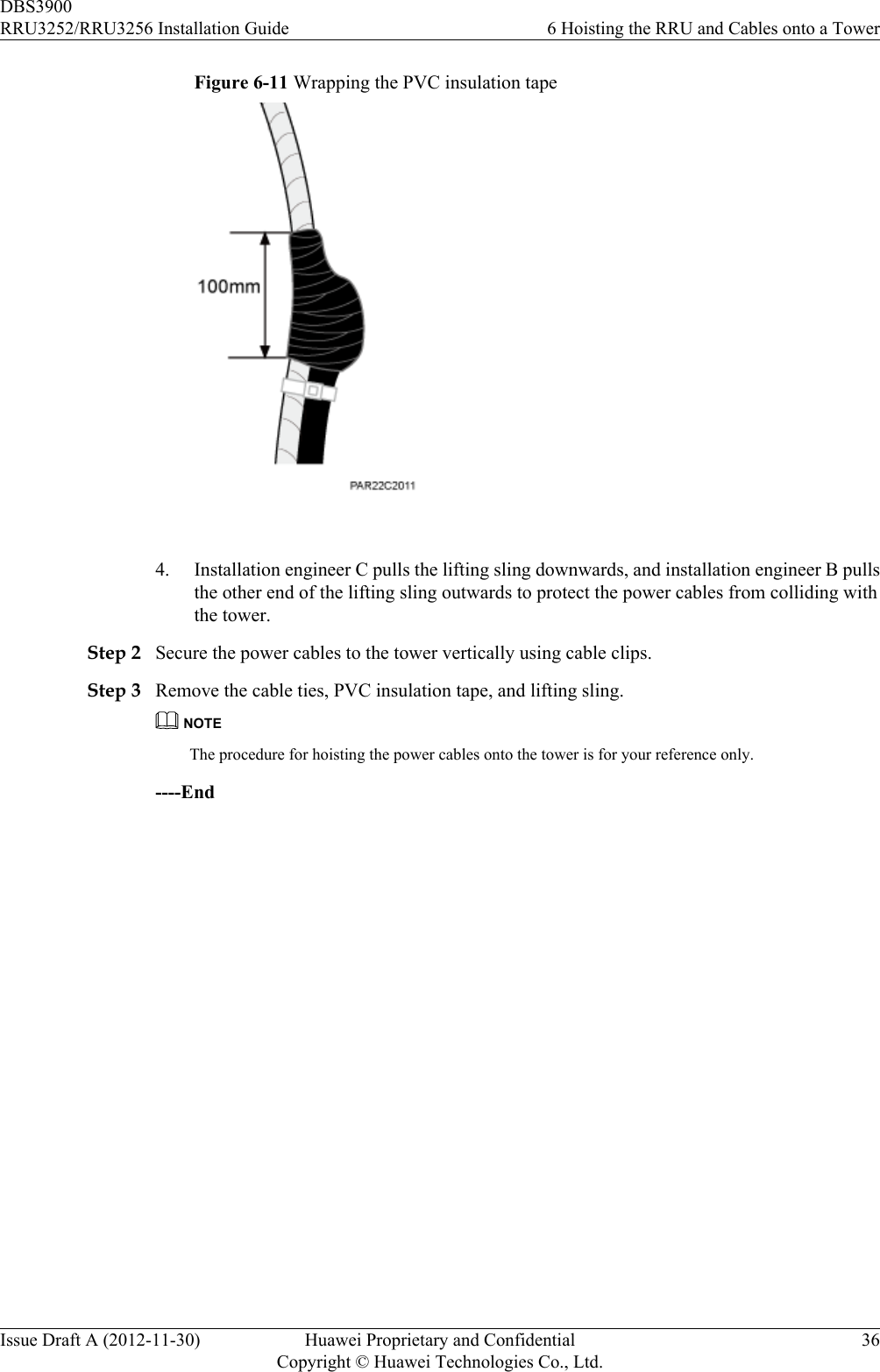
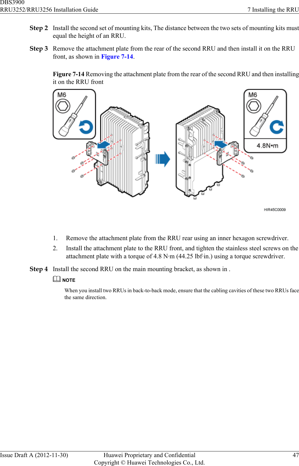
![Figure 6-3 Binding the RRU(1) Lifting sling (2) Lifting eye (3) Traction sling (4) Handle CAUTIONlThe load-bearing capacity of each sling must be greater than 200 kg (441 lb) and thediameter of each sling must be less than 25 mm (0.98 in.). The angle at the top of thelifting sling [by the knot] must not be greater than 60 degrees.lWhen hoisting the RRU and mounting kits onto the tower, protect them from collidingwith the ground and tower.lHoist the RRU onto the tower before it is installed on a pole, angle steel, or U-steel.lDo not hoist the RRU by the handle or lifting eye only, as shown in Figure 6-4 andFigure 6-5.DBS3900RRU3252/RRU3256 Installation Guide 6 Hoisting the RRU and Cables onto a TowerIssue Draft A (2012-11-30) Huawei Proprietary and ConfidentialCopyright © Huawei Technologies Co., Ltd.29](https://usermanual.wiki/Huawei-Technologies/RRU3252B41.Manual-RRU3252-Installation-Guide-EN-pdf/User-Guide-1922955-Page-37.png)
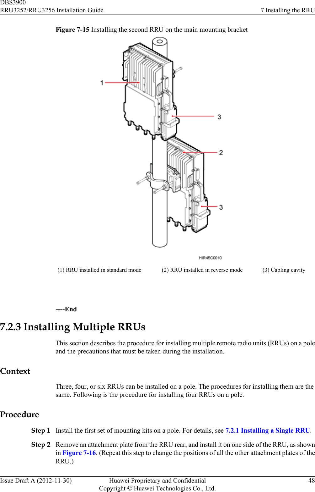
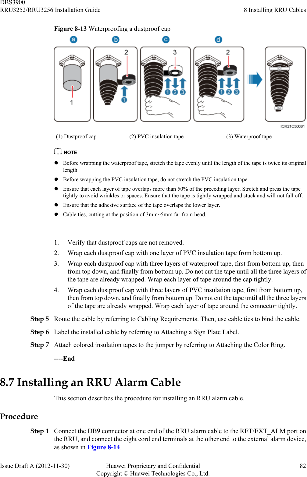
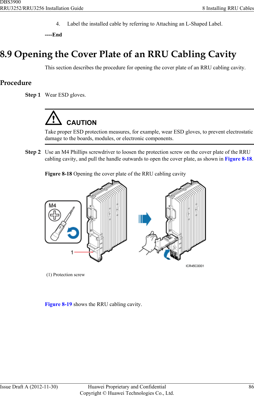
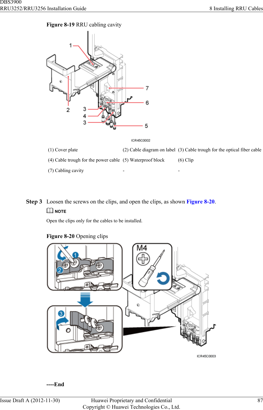
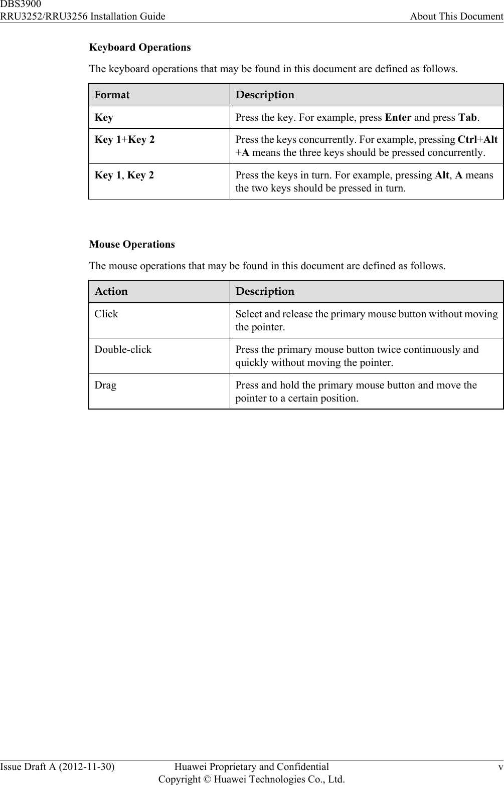
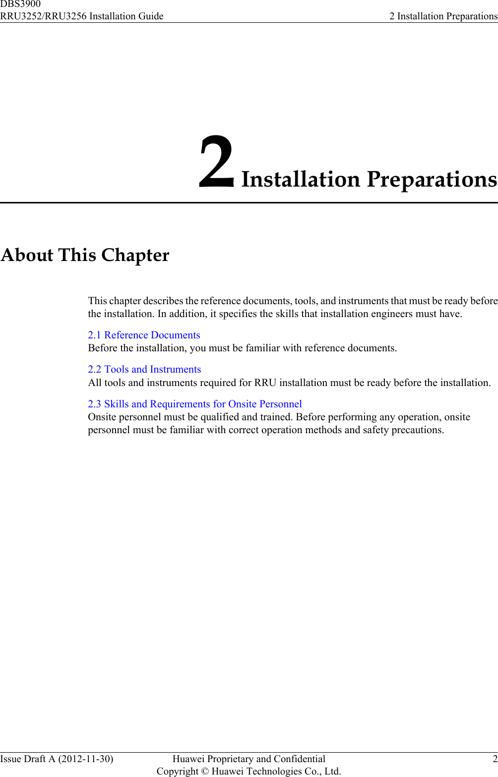
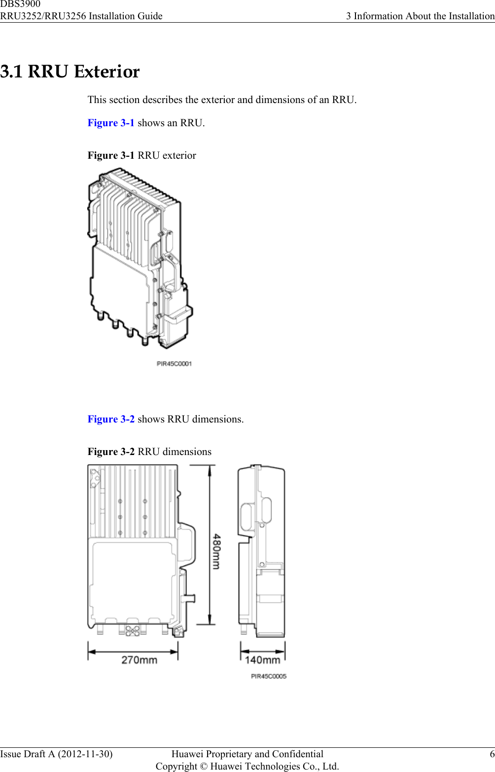
![8.1 Cabling RequirementsCables must be routed according to the specified cabling requirements to prevent signalinterference.NOTEIf a cable listed below is not required, skip the routing requirements of the cable.General Cabling RequirementsRequirements for Bending RadiuslThe bending radius of the 7/8'' feeder must be more than 250 mm (9.84 in.), and the bendingradius of the 5/4'' feeder must be more than 380 mm (14.96 in.).lThe bending radius of the 1/4'' jumper, ordinary 1/2'' jumper, super-flexible 1/2'' jumper,and RG-8U jumper must be more than 35 mm (1.38 in.), 127 mm (5 in.), 50 mm (1.97 in.),and 50 mm (1.97 in.), respectively.lThe bending radius of the power cable or PGND cable must be at least three times thediameter of the cable.lThe bending radius of a fiber optic cable is at least 20 times the diameter of the fiber opticcable, and the minimum bending radius of the breakout cable at each end of the fiber opticcable is 30 mm (1.18 in.).lThe bending radius of the E1/T1 cable must be at least three times the diameter of the cable.lThe bending radius of the signal cable must be at least five times the diameter of the cable.Requirements for Cable BindinglThe same types of cable must be bound together.lDifferent types of cable must be separately routed with the minimum spacing of 30 mm(1.18 in.) and cannot be entangled.lThe cables must be bound tightly and neatly. The sheaths of the cables must not be damaged.lCable ties are installed in the same direction, and those at the same horizontal line must bein a straight line.lThe excess of indoor cable ties is trimmed off, and the excess of outdoor cable ties allowsabout 5 mm (0.2 in.), without remaining rough edges.lLabels or nameplates must be attached to both ends, joints, or turns of cables after they areinstalled.Security RequirementslCables should be placed away from sharp objects or wall burrs. If these positions areinevitable, protect the cables with protection pipes.lCables must be routed away from heat sources, or heat-insulation materials are addedbetween cables and heat sources.lSufficient slack (recommended for about 0.1 m [0.33 ft.]) is provided in cables at turns orthe position close to a device, facilitating cable and device maintenance.Indoor Cabling RequirementslCables are routed indoors through the feeder window.DBS3900RRU3252/RRU3256 Installation Guide 8 Installing RRU CablesIssue Draft A (2012-11-30) Huawei Proprietary and ConfidentialCopyright © Huawei Technologies Co., Ltd.67](https://usermanual.wiki/Huawei-Technologies/RRU3252B41.Manual-RRU3252-Installation-Guide-EN-pdf/User-Guide-1922955-Page-75.png)