Huawei Technologies RRU32602G6 Remote Radio Unit User Manual Installation Guide
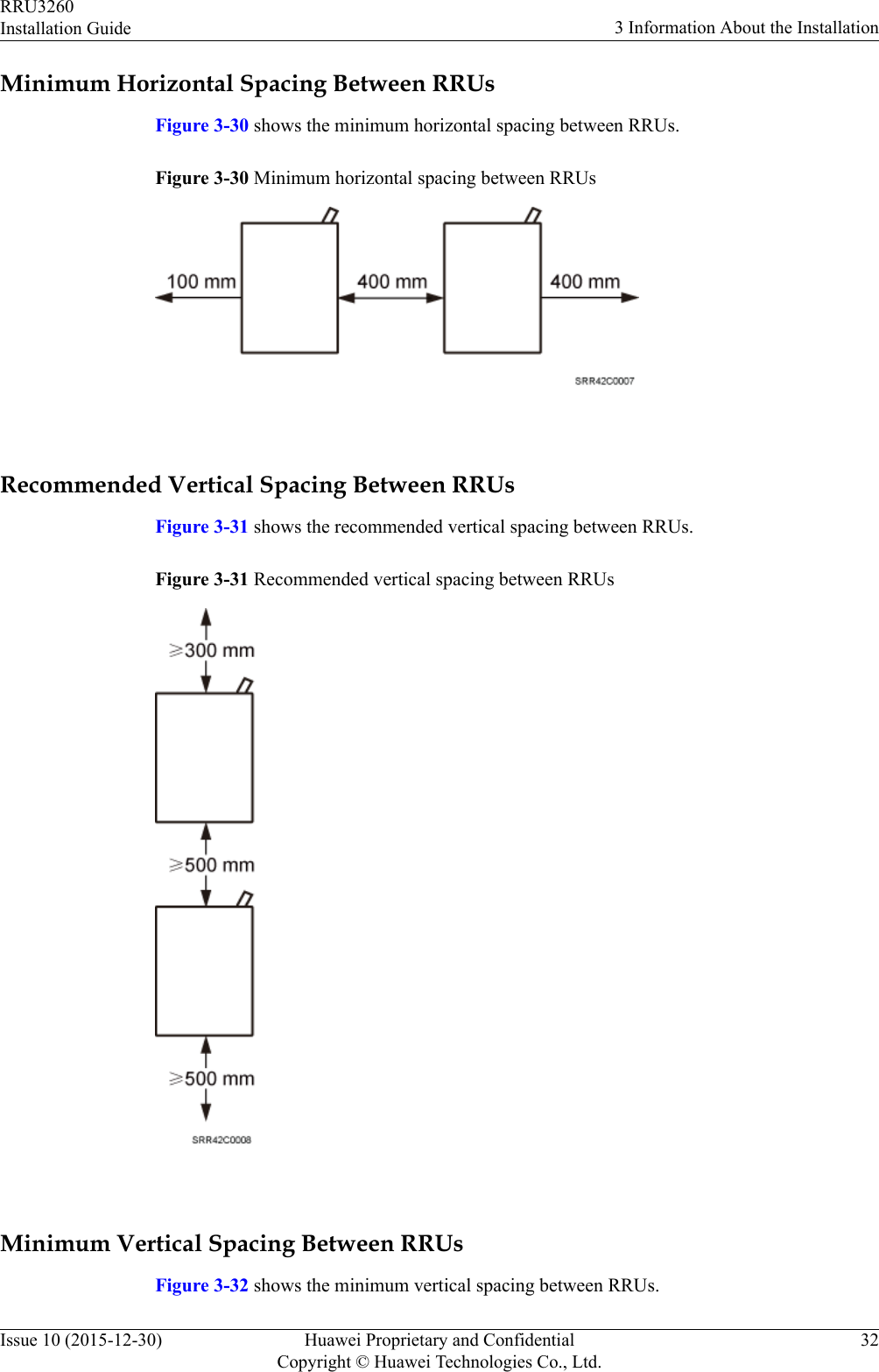
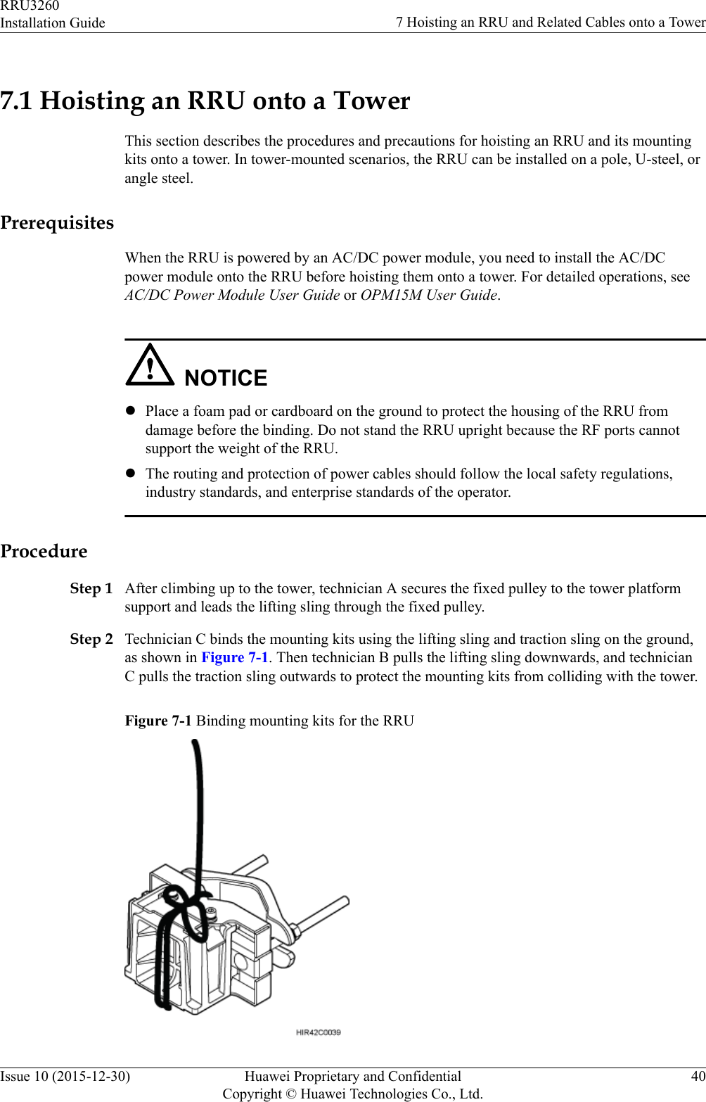
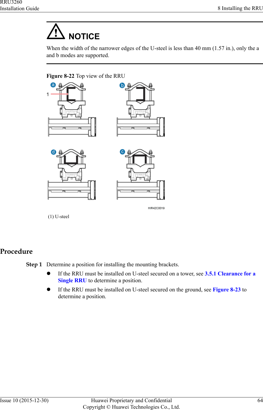
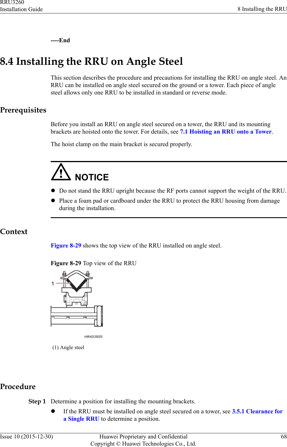
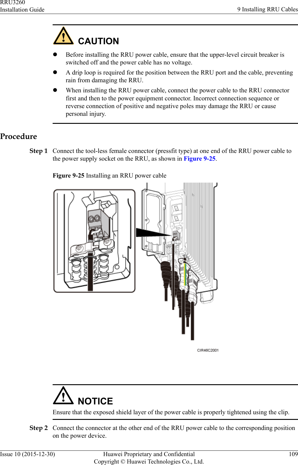
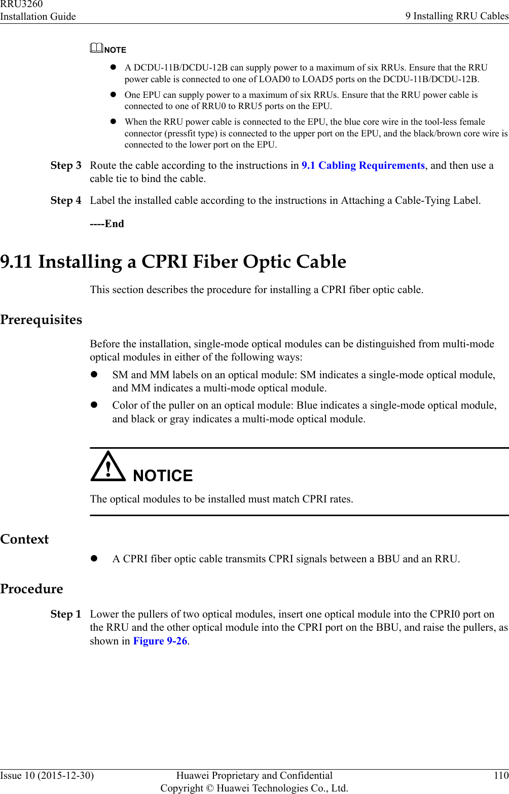
Huawei Technologies Co.,Ltd Remote Radio Unit Installation Guide
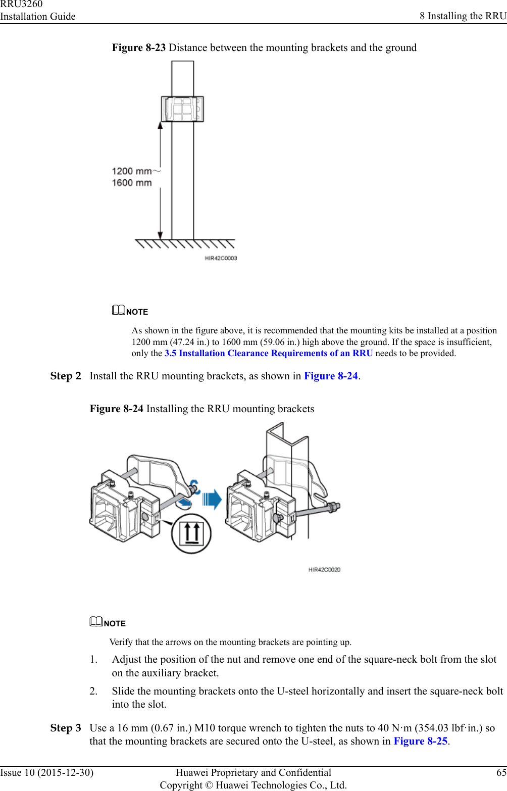
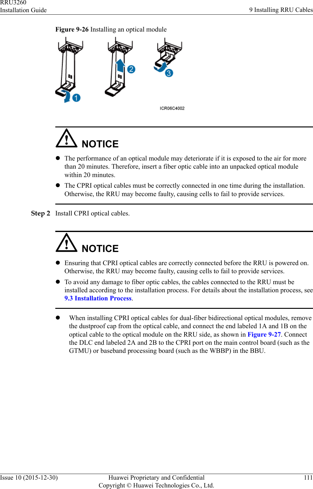
UserManual.wiki
>
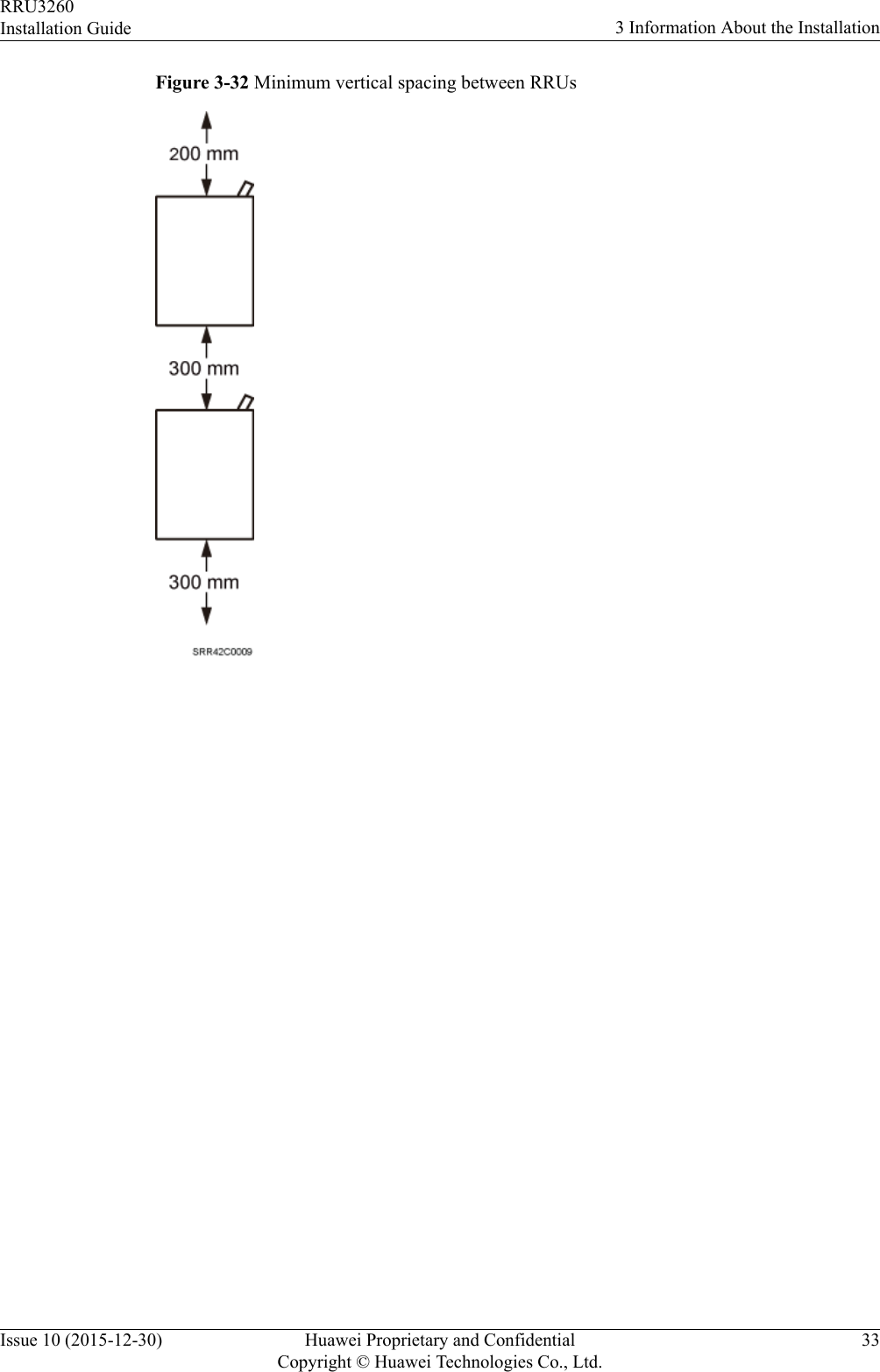
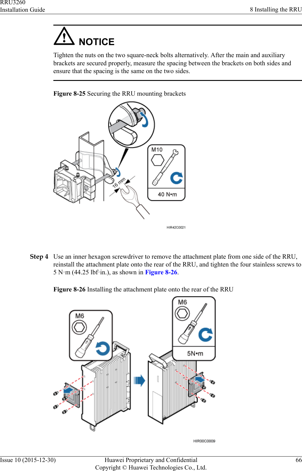
Huawei Technologies
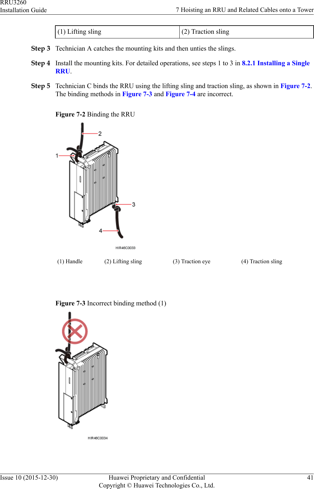
>
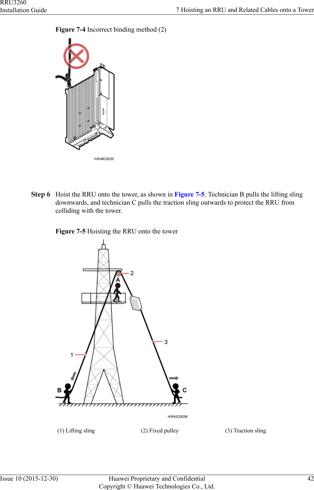
RRU32602G6 User Manual
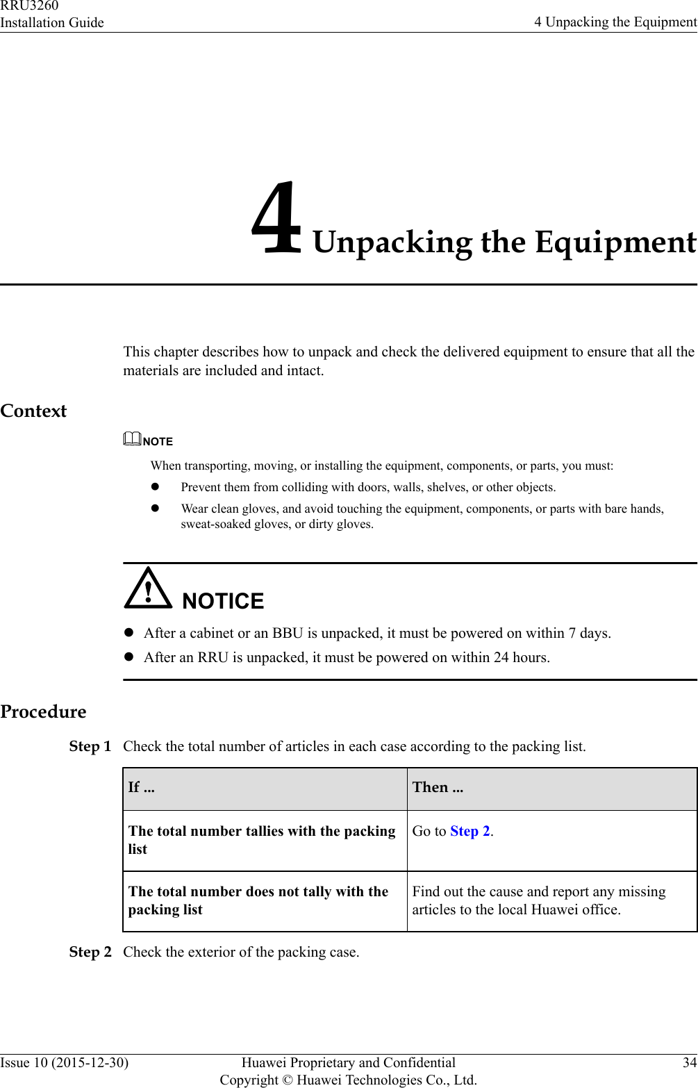
>
Installation Guide
Contents
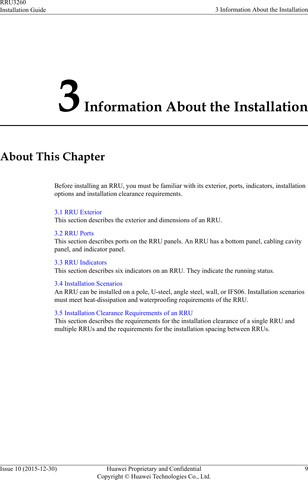
1.
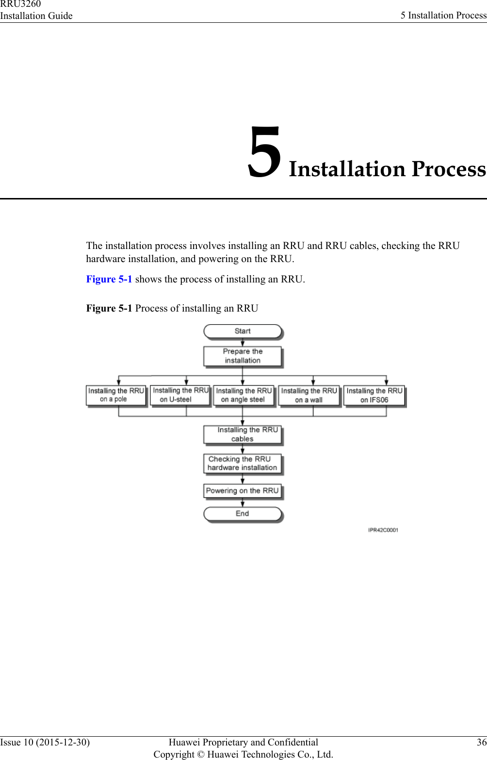
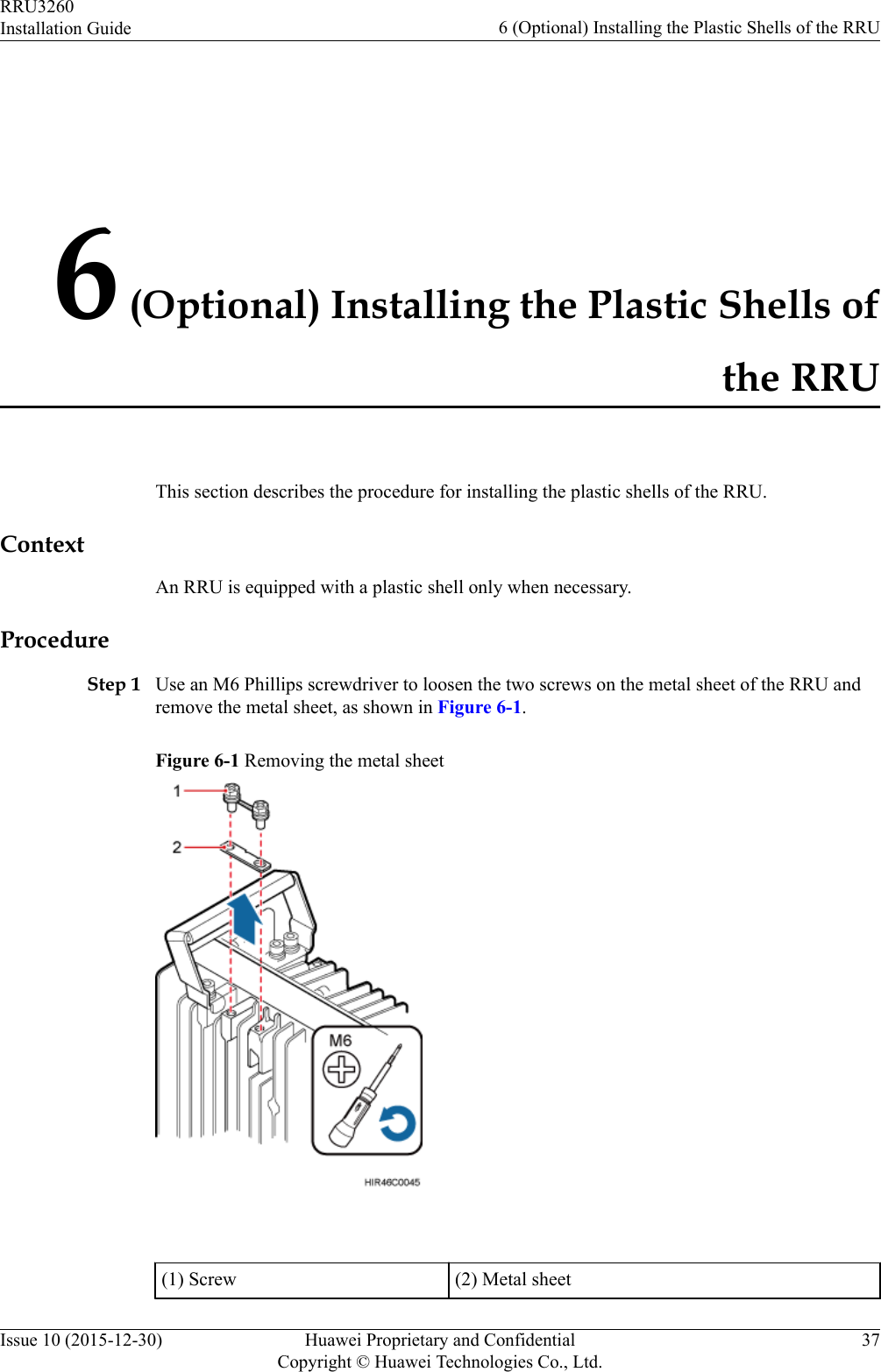
Installation Guide
2.
Safety information
Installation Guide
Navigation menu
Upload a User Manual
Namespaces
Wiki Guide
HTML
PDF
Info
Views
User Manual
Discussion / Help
Navigation
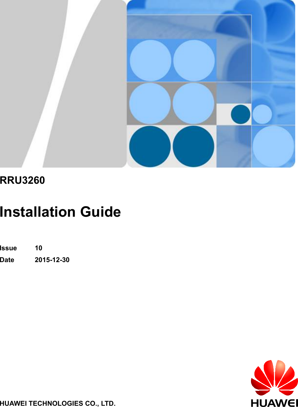
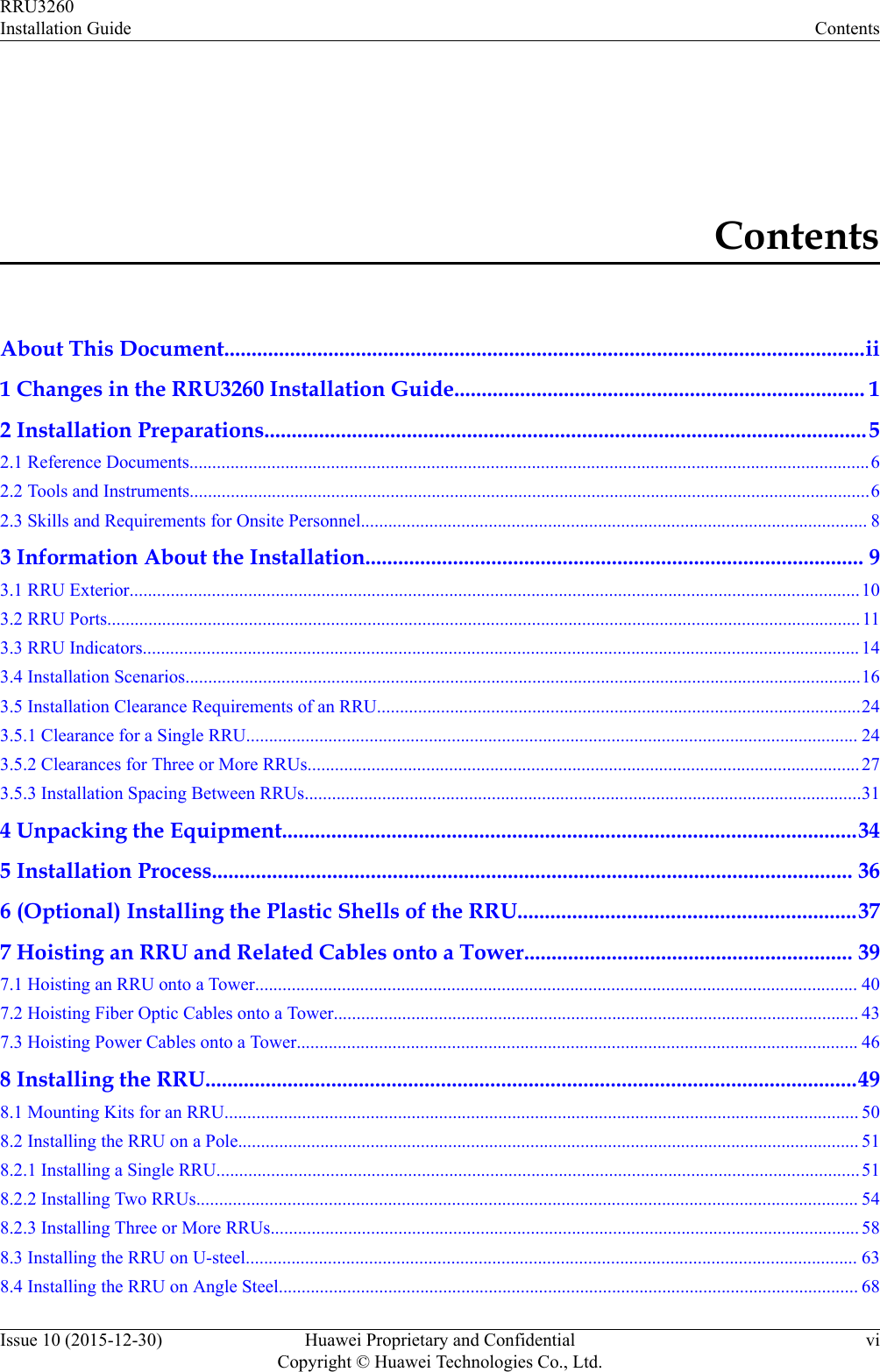
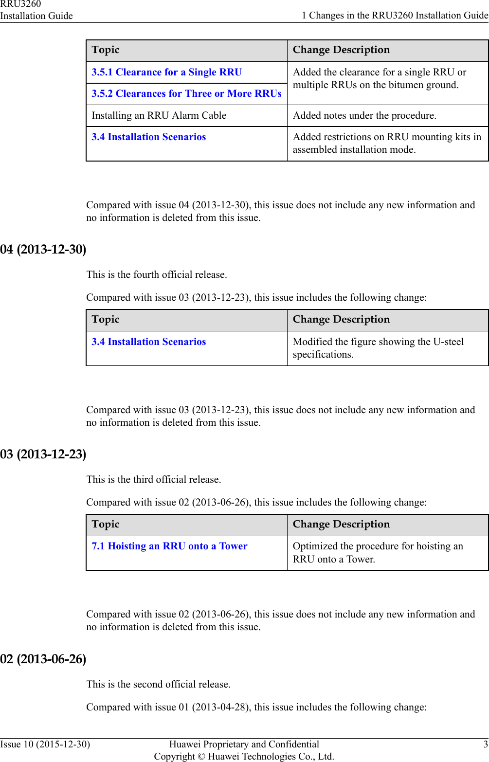
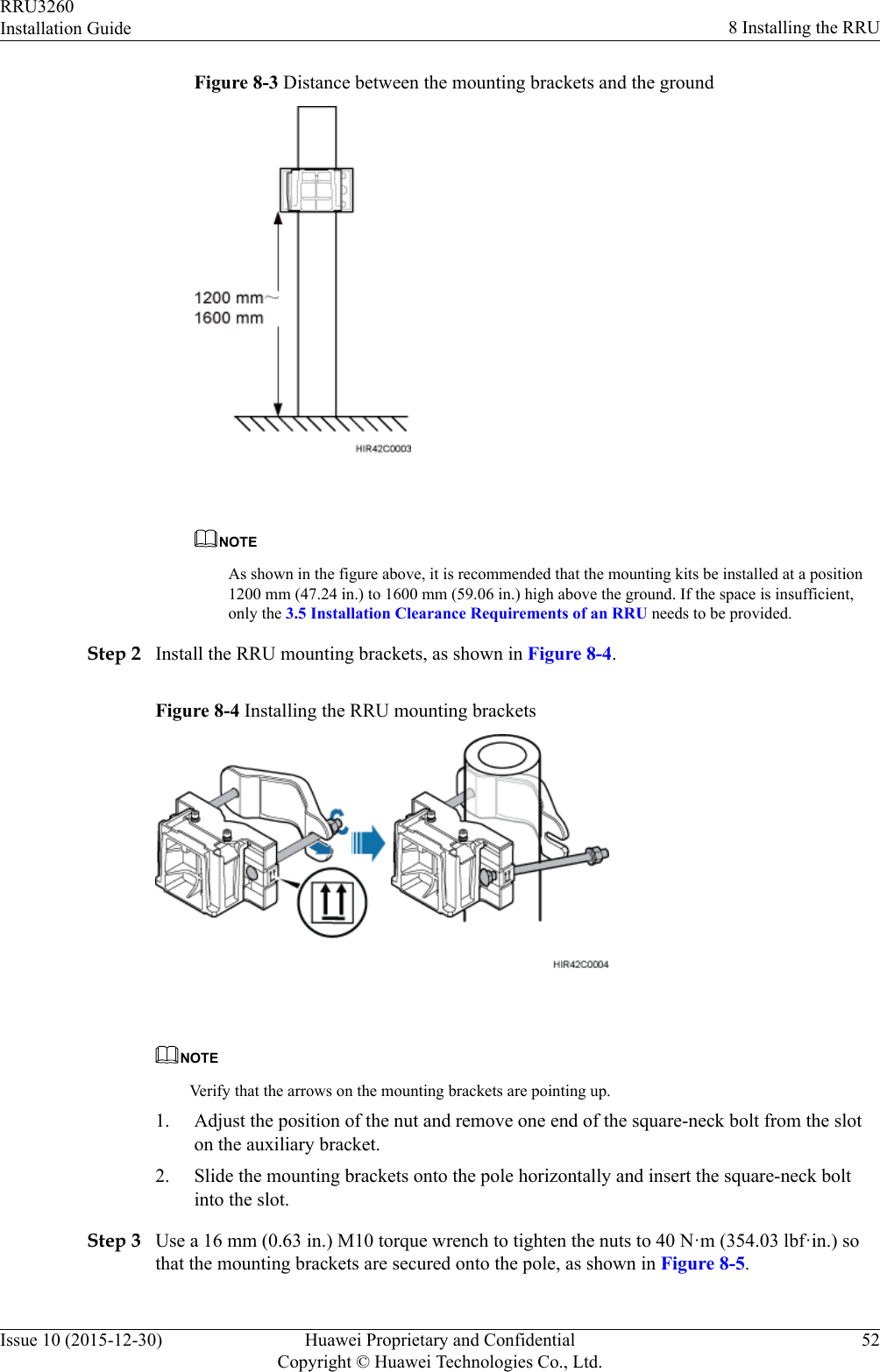
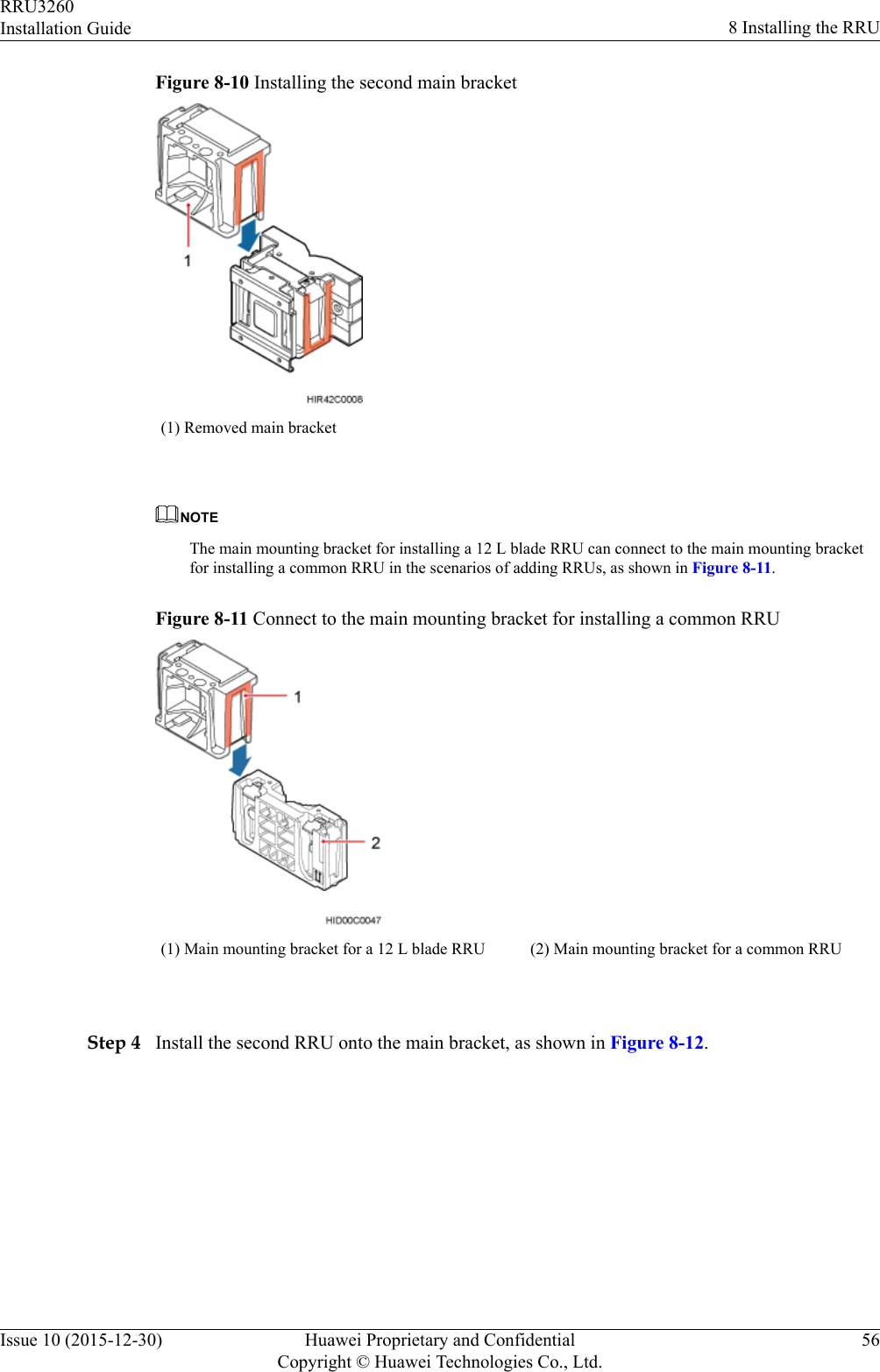
![Symbol DescriptionIndicates a potentially hazardous situation which, if notavoided, could result in equipment damage, data loss,performance deterioration, or unanticipated results.NOTICE is used to address practices not related to personalinjury.Calls attention to important information, best practices andtips.NOTE is used to address information not related topersonal injury, equipment damage, and environmentdeterioration. General ConventionsThe general conventions that may be found in this document are defined as follows.Convention DescriptionTimes New Roman Normal paragraphs are in Times New Roman.Boldface Names of files, directories, folders, and users are inboldface. For example, log in as user root.Italic Book titles are in italics.Courier New Examples of information displayed on the screen are inCourier New. Command ConventionsThe command conventions that may be found in this document are defined as follows.Convention DescriptionBoldface The keywords of a command line are in boldface.Italic Command arguments are in italics.[ ] Items (keywords or arguments) in brackets [ ] are optional.{ x | y | ... } Optional items are grouped in braces and separated byvertical bars. One item is selected.[ x | y | ... ] Optional items are grouped in brackets and separated byvertical bars. One item is selected or no item is selected.{ x | y | ... }*Optional items are grouped in braces and separated byvertical bars. A minimum of one item or a maximum of allitems can be selected.RRU3260Installation Guide About This DocumentIssue 10 (2015-12-30) Huawei Proprietary and ConfidentialCopyright © Huawei Technologies Co., Ltd.iv](https://usermanual.wiki/Huawei-Technologies/RRU32602G6.Installation-Guide/User-Guide-3022722-Page-5.png)
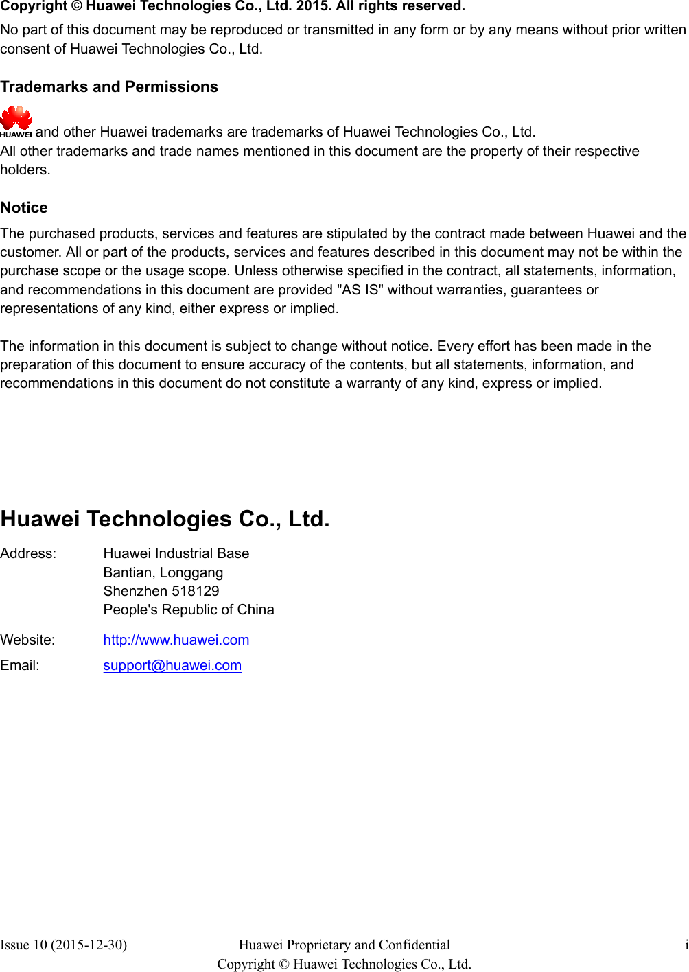
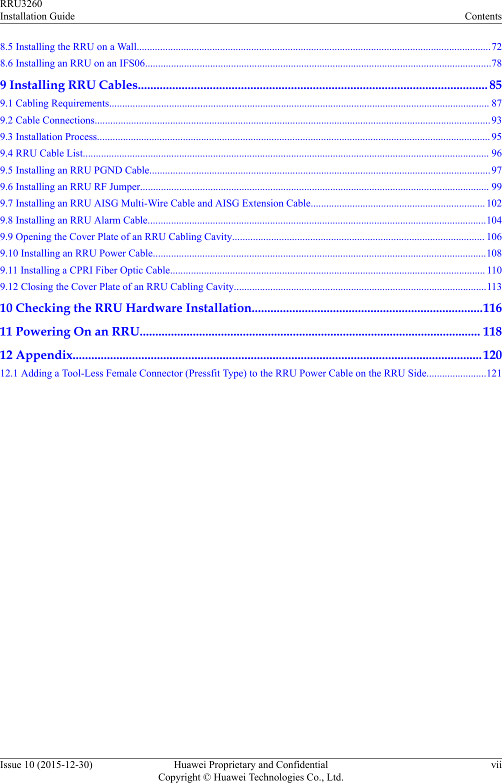
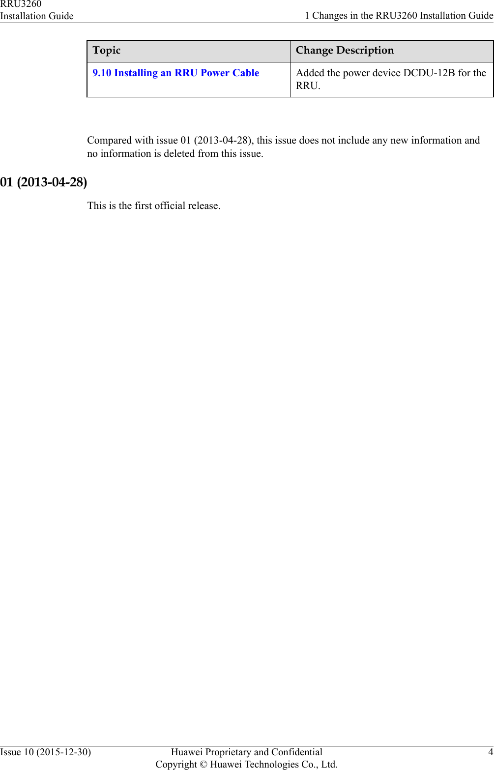
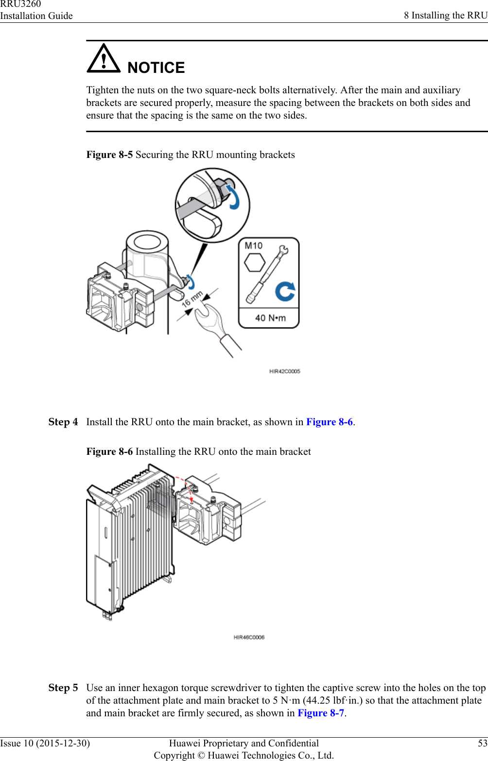
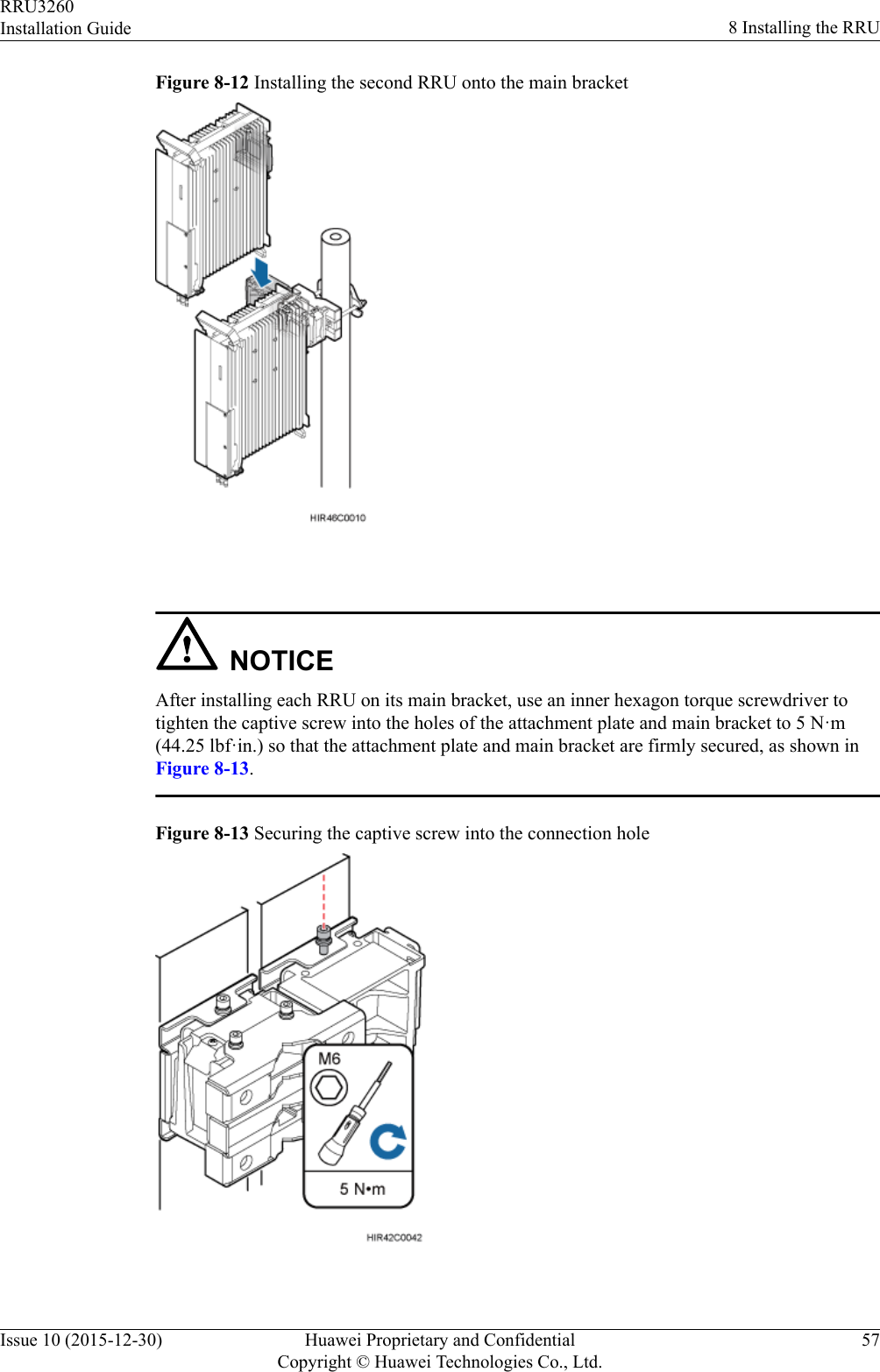
![Convention Description[ x | y | ... ]*Optional items are grouped in brackets and separated byvertical bars. Several items or no item can be selected. GUI ConventionsThe GUI conventions that may be found in this document are defined as follows.Convention DescriptionBoldface Buttons, menus, parameters, tabs, window, and dialog titlesare in boldface. For example, click OK.> Multi-level menus are in boldface and separated by the ">"signs. For example, choose File > Create > Folder. Keyboard OperationsThe keyboard operations that may be found in this document are defined as follows.Format DescriptionKey Press the key. For example, press Enter and press Tab.Key 1+Key 2 Press the keys concurrently. For example, pressing Ctrl+Alt+A means the three keys should be pressedconcurrently.Key 1, Key 2 Press the keys in turn. For example, pressing Alt, A meansthe two keys should be pressed in turn. Mouse OperationsThe mouse operations that may be found in this document are defined as follows.Action DescriptionClick Select and release the primary mouse button withoutmoving the pointer.Double-click Press the primary mouse button twice continuously andquickly without moving the pointer.Drag Press and hold the primary mouse button and move thepointer to a certain position.RRU3260Installation Guide About This DocumentIssue 10 (2015-12-30) Huawei Proprietary and ConfidentialCopyright © Huawei Technologies Co., Ltd.v](https://usermanual.wiki/Huawei-Technologies/RRU32602G6.Installation-Guide/User-Guide-3022722-Page-6.png)
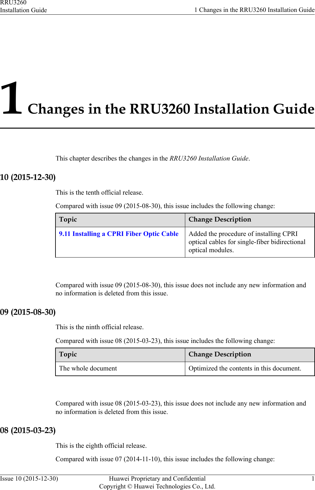
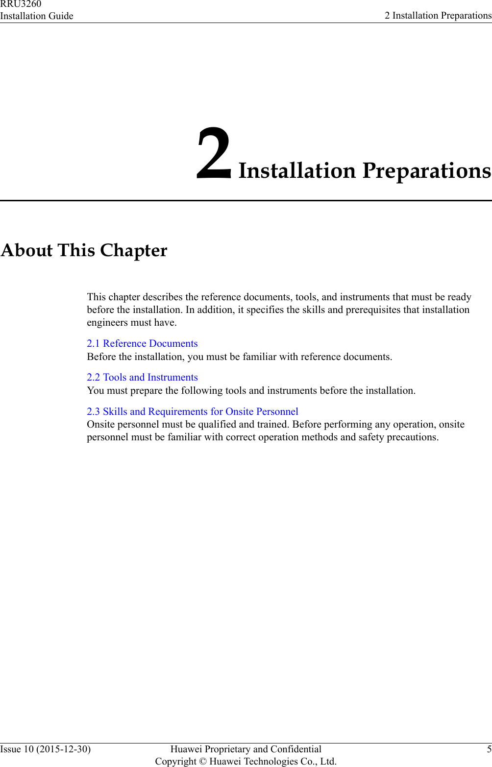
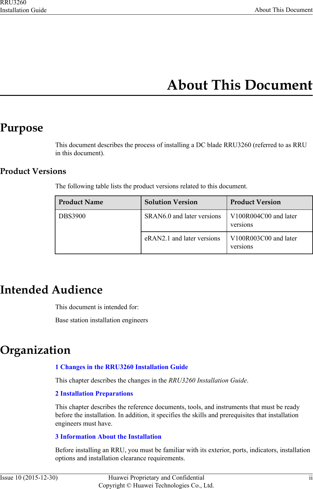
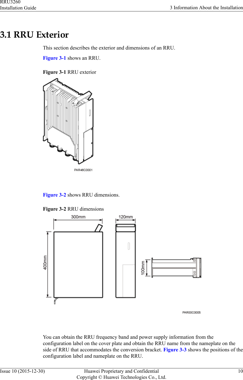
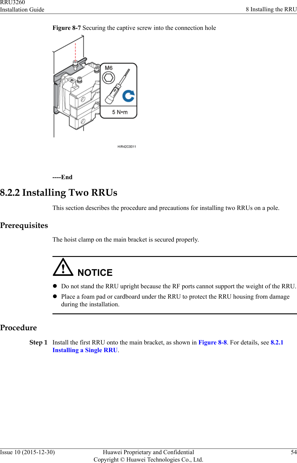
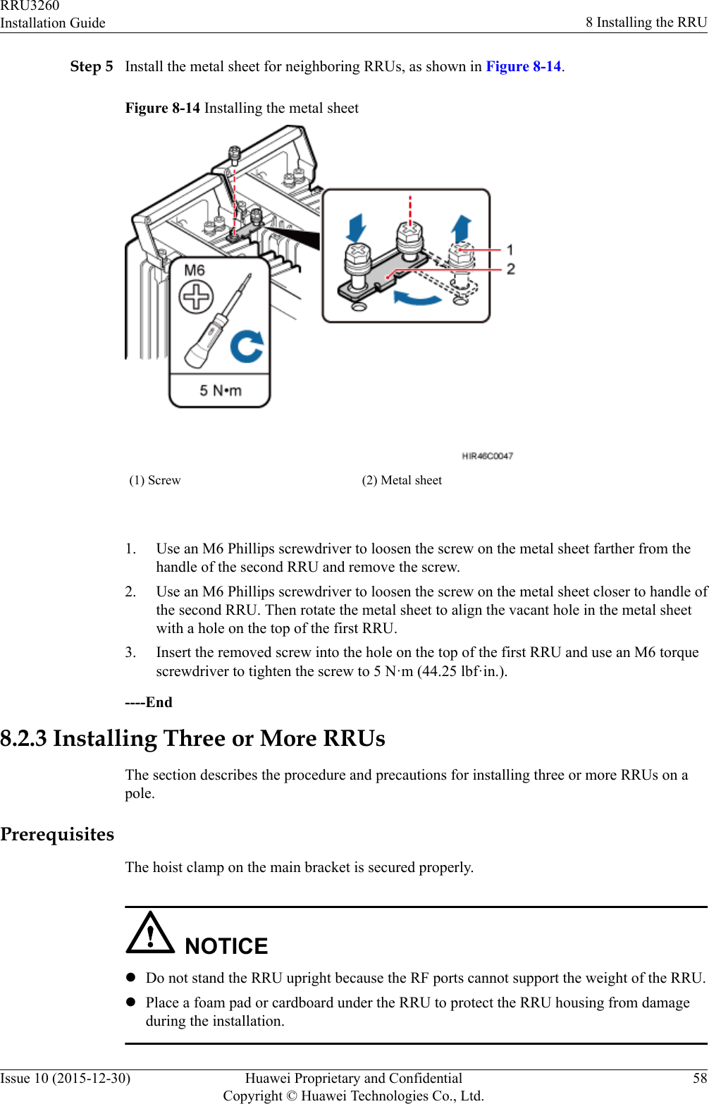
![Utility knife Cable cutter Adjustable wrench (size ≥ 32mm [1.26 in.])Torque wrenchSize: 16 mm (0.63 in.) and32 mm (1.26 in.)Combination wrenchSize: 16 mm (0.63 in.) and32 mm (1.26 in.)Level Torque screwdriver5 mm5 mm(M3 to M6)(M3 to M6)Torque socketMultimeter Marker (diameter ≤ 10 mm[0.39 in.])Measuring tapeInner hexagon wrench5 mmFixed pulley(weight-bearing capacity > 500 kgor 1102.5 lb)Lifting slingHydraulic pliers - -RRU3260Installation Guide 2 Installation PreparationsIssue 10 (2015-12-30) Huawei Proprietary and ConfidentialCopyright © Huawei Technologies Co., Ltd.7](https://usermanual.wiki/Huawei-Technologies/RRU32602G6.Installation-Guide/User-Guide-3022722-Page-15.png)
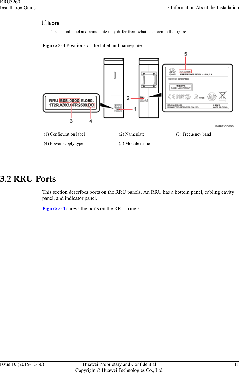
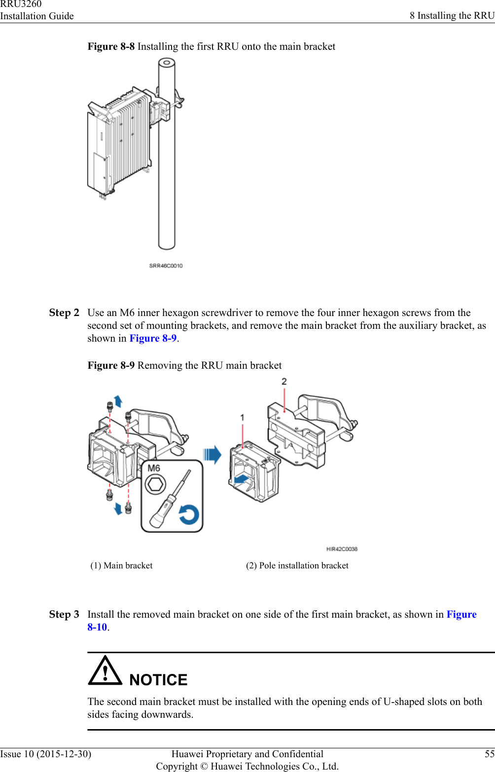
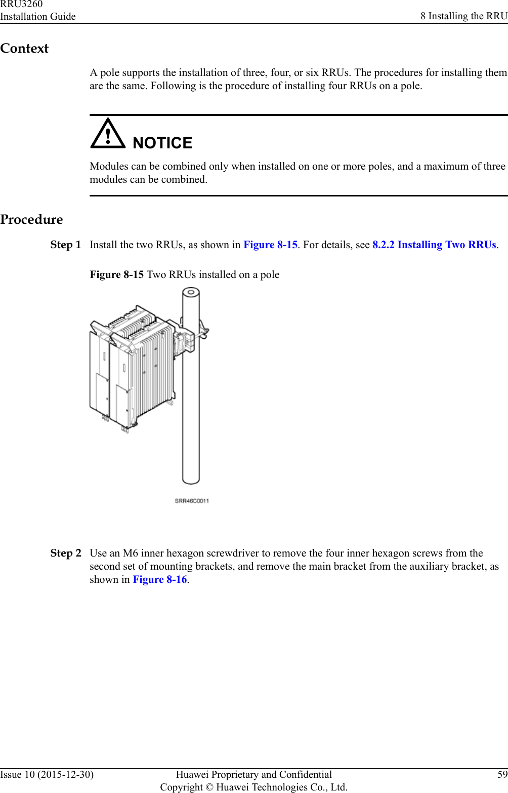

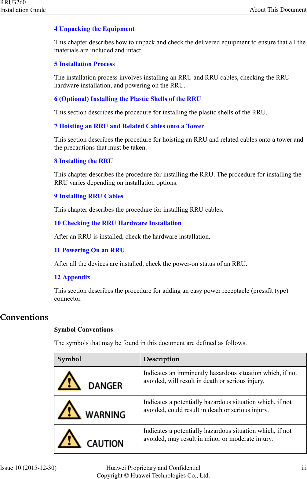
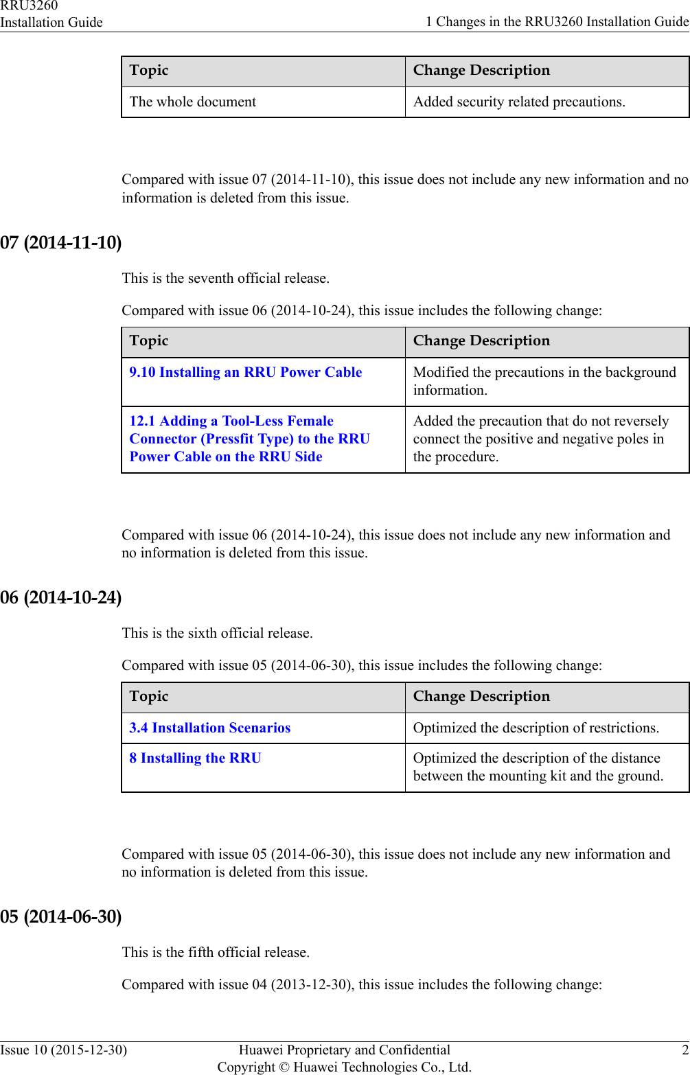
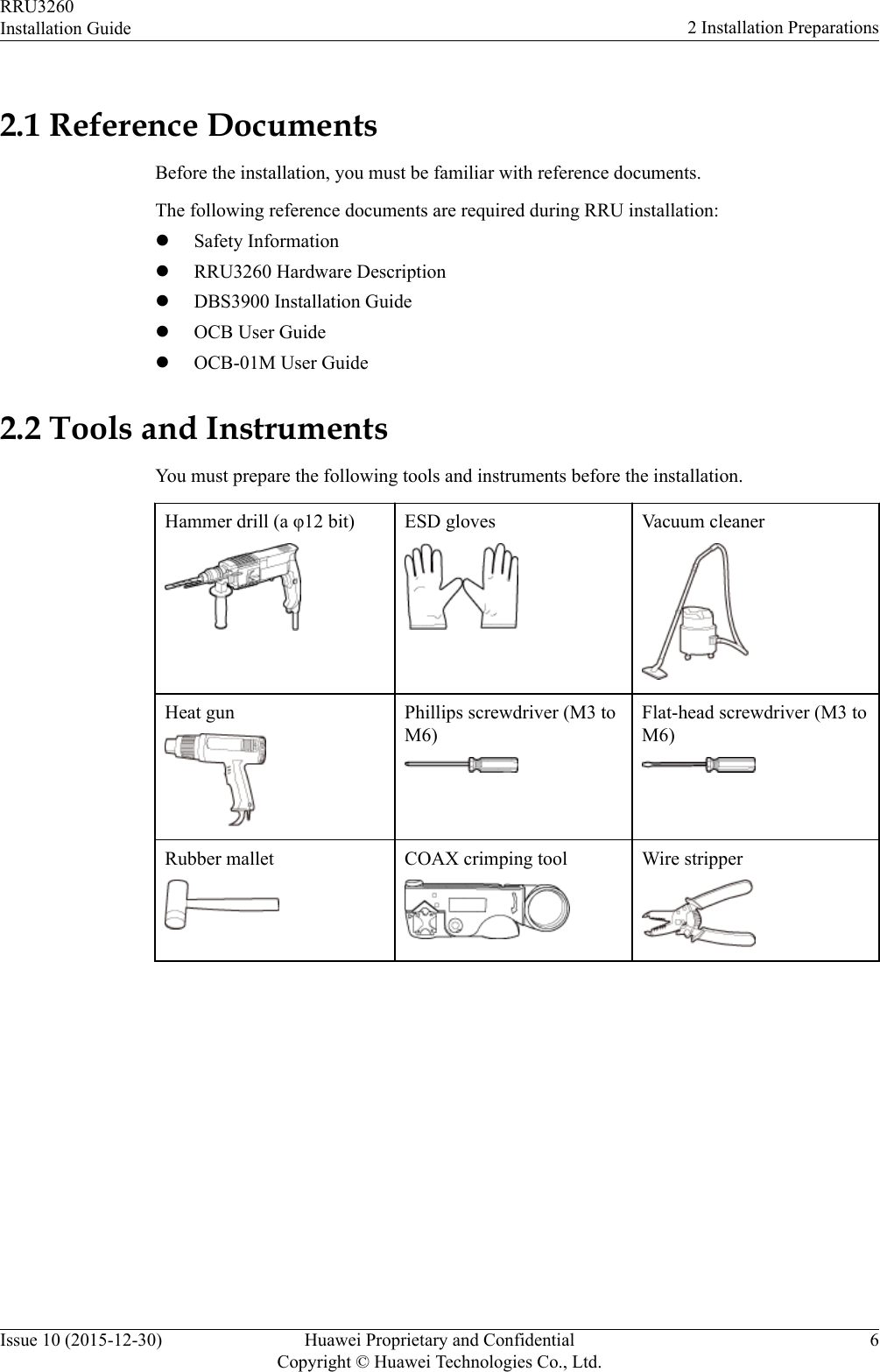
![Figure 12-8 Stripping the sheath off the power cable NOTICEEach core wire is exposed outside the tool-less female connector (pressfit type) for 1.5 mm(0.059 [in.]), as shown in Figure 12-9.Figure 12-9 Inserting core wires into the tool-less female connector (pressfit type)----EndRRU3260Installation Guide 12 AppendixIssue 10 (2015-12-30) Huawei Proprietary and ConfidentialCopyright © Huawei Technologies Co., Ltd.124](https://usermanual.wiki/Huawei-Technologies/RRU32602G6.Installation-Guide/User-Guide-3022722-Page-132.png)