Huawei Technologies RRU3606-AWS Remote Radio Unit User Manual
Huawei Technologies Co.,Ltd Remote Radio Unit
Contents
- 1. User Manual
- 2. User manual
User Manual
Huawei Proprietary and Confidential
Copyright © Huawei Technologies Co., Ltd.
1 RRU3606 User Guide
About This Chapter
Purpose
This describes hardware configuration, software installation, and routine maintenance of the
RRU3606.
Related Versions
The following table lists the product version related to this document.
Product Name Related Versions
RRU3606 V400R006
Intended Audience
This document is intended for:
lField engineers
lSystem engineers
Change History
Version Record
01 (2008-02-25) Initial release.
Organization
1.1 Safety Information
1.2 Hardware Configuration of the RRU3606
1 RRU3606 User Guide
Issue () Huawei Proprietary and Confidential
Copyright © Huawei Technologies Co., Ltd.
1-1

This describes the configuration of equipment and cables of the RRU3606.
1.3 Installing Hardware for the RRU3606
This describes the hardware installation, cable distribution, and installation checklist for the
RRU3606.
1.4 Maintaining the RRU3606
This describes how to maintain the RRU3606.
1 RRU3606 User Guide
1-2 Huawei Proprietary and Confidential
Copyright © Huawei Technologies Co., Ltd.
Issue ()
1.1 Safety Information
1.1.1 Safety Precautions
This section describes certain safety precautions and helps to choose the measurement device
and testing device. Read and follow these safety precautions before installing, operating, and
maintaining Huawei devices.
Following All Safety Precautions
Before any operation, read the instructions and precautions in this document carefully to
minimize the possibility of accidents.
The Danger, Caution, and Note items in the package of documents do not cover all the safety
precautions that must be followed. They only provide the generic safety precautions for
operations.
Symbols
DANGER
This symbol indicates that casualty or serious accident may occur if you ignore the safety
instruction.
CAUTION
This symbol indicates that serious or major injury may occur if you ignore the safety instruction.
NOTE
This symbol indicates that the operation may be easier if you pay attention to the safety instruction.
Complying with the Local Safety Regulations
When operating the device, comply with the local safety regulations. The safety precautions
provided in the documents are supplementary. You must comply with the local safety
regulations.
General Installation Requirements
The personnel in charge of installation and maintenance must be trained and master the correct
operating methods and safety precautions before beginning work.
The rules for installing and maintaining the device are as follows:
lOnly the trained and qualified personnel can install, operate and maintain the device.
1 RRU3606 User Guide
Issue () Huawei Proprietary and Confidential
Copyright © Huawei Technologies Co., Ltd.
1-3

lOnly the qualified specialists are allowed to remove the safety facilities, and repair the
device.
lAny replacement of the device or part of the device (including the software) or any change
made to the device must be performed by qualified or authorized personnel of Huawei.
lAny fault or error that might cause safety problems must be reported immediately to the
personnel in charge.
Grounding Requirements
The following requirements are applicable to the device to be grounded:
lGround the device before installation and remove the ground cable after uninstallation.
lDo not operate the device in the absence of a ground conductor. Do not damage the ground
conductor.
lThe unit (or system) must be permanently connected to the protection ground before
operation. Check the electrical connection of the device before operation and ensure that
the device is reliably grounded.
Safety of Personnel
Ensure the following:
lWhen lightning strikes, do not operate the device and cables.
lWhen lightning strikes, unplug the AC power connector. Do not use the fixed terminal or
touch the terminal or antenna connector.
NOTE
The previous two requirements are suitable for the wireless fixed terminal.
lTo prevent electric shock, do not connect safety extra-low voltage (SELV) circuits to
telecommunication network voltage (TNV) circuits.
lTo prevent laser radiation from injuring your eyes, never look into the optical fiber outlet
with unaided eyes.
lTo prevent electric shock and burns, wear the electrostatic discharge (ESD) clothing, gloves
and wrist strap, and remove conductors such as jewelry and watch before operation.
Device Safety
lBefore operation, the device must be secured on the floor or other fixed objects, such as
the walls and the mounting racks.
lDo not block ventilation openings while the system is running.
lWhen installing the panel, tighten the screw with the tool.
1 RRU3606 User Guide
1-4 Huawei Proprietary and Confidential
Copyright © Huawei Technologies Co., Ltd.
Issue ()
1.1.2 Electricity Safety
High Voltage
DANGER
lThe high voltage power supply provides power for running the system. Direct contact with
the high voltage power supply or contact through damp objects may result in fatal danger.
lNon-standard and improper high voltage operations may result in fire and electric shock.
lThe personnel who install the AC facility must be qualified to perform operations on high
voltage and AC power supply facilities.
lWhen installing the AC power supply facility, follow the local safety regulations.
lWhen operating the AC power supply facility, follow the local safety regulations.
lWhen operating the high voltage and AC power supply facilities, use the specific tools
instead of common tools.
lWhen the operation is performed in a damp environment, ensure that water is kept off the
device. If the cabinet is damp or wet, shut down the power supply immediately.
Thunderstorm
The following requirements are suitable only for the wireless base station or the device with an
antenna or GPS antenna.
DANGER
In a thunderstorm, do not perform operations on high voltage and AC power supply facilities or
on a steel tower and mast.
High Electrical Leakage
CAUTION
Ground the device before powering on the device. Otherwise, the personnel and device are in
danger.
If the "high electrical leakage" flag is stuck to the power terminal of the device, you must ground
the device before powering it on.
1 RRU3606 User Guide
Issue () Huawei Proprietary and Confidential
Copyright © Huawei Technologies Co., Ltd.
1-5
Power Cable
CAUTION
Do not install and remove the power cable with a live line. Transient contact between the core
of the power cable and the conductor may generate electric arc or spark, which may cause fire
or eye injury.
lBefore installing or removing the power cable, turn off the power switch.
lBefore connecting the power cable, ensure that the power cable and label comply with the
requirements of the actual installation.
Fuse
CAUTION
To ensure that the system runs safely, when a fuse blows, replace it with a fuse of the same type
and specifications.
Electrostatic Discharge
CAUTION
The static electricity generated by the human body may damage the electrostatic sensitive
components on the circuit board, such as the large-scale integrated circuit (LIC).
In the following situations, the human body generates a static electromagnetic field:
lMovement of body parts
lClothes friction
lFriction between shoes and the ground
lHolding plastic in hand
The static electromagnetic field will remain within the human body for a long time.
Before contacting the device, plug boards, circuit boards, and application specific integrated
circuits (ASICs), wear a grounded ESD wrist strap. It can prevent the sensitive components from
being damaged by the static electricity in the human body.
Figure 1-1shows how to wear an ESD wrist strap.
1 RRU3606 User Guide
1-6 Huawei Proprietary and Confidential
Copyright © Huawei Technologies Co., Ltd.
Issue ()
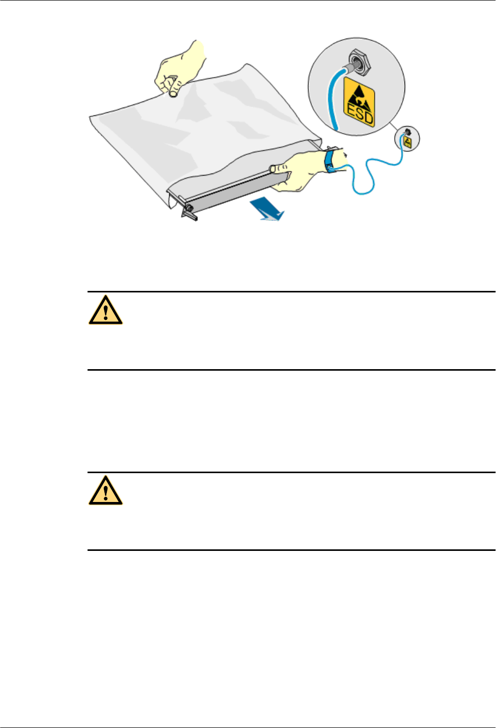
Figure 1-1 Wearing an ESD wrist strap
1.1.3 Inflammable Environment
DANGER
Do not place the device in the environment that has inflammable and explosive air or fog. Do
not perform any operation in this environment.
Any operation of the electrical device in the inflammable environment causes danger.
1.1.4 Battery
Storage Battery
DANGER
Before handling the storage battery, read the safety precautions for the handling and connection
of the storage battery.
Incorrect operation of storage batteries may cause danger. During operation, ensure the
following:
lPrevent any short-circuit.
lPrevent the electrolyte from overflowing and leakage.
Electrolyte overflow may damage the device. It will corrode the metal parts and the circuit
boards, and ultimately damage the device and cause short-circuit of the circuit boards.
General Operations
Before installing and maintaining the storage battery, ensure the following:
1 RRU3606 User Guide
Issue () Huawei Proprietary and Confidential
Copyright © Huawei Technologies Co., Ltd.
1-7
lUse special insulation tools.
lUse eye protection devices and operate with care.
lWear rubber gloves and an apron in case of an electrolyte overflow.
lAlways keep the battery upright when moving. Do not place the battery upside down or tilt
it.
Short-Circuit
DANGER
Short-circuit of the battery may cause injury. Although the voltage of a battery is low, high
transient current generated by short-circuit will release a surge of power.
Keep metal objects away from the battery to prevent short circuit. If they have to be used,
disconnect the battery in use before performing any other operation.
Harmful Gas
CAUTION
lDo not use unsealed lead-acid storage batteries, because the gas emitted from it may result
in fire or device corrosion.
lLay the storage battery horizontally and fix it properly.
The lead-acid storage battery in use will emit flammable gas. Therefore, store it in a place with
good ventilation and take precautions against fire.
High Temperature
CAUTION
High temperature may result in distortion, damage, and electrolyte overflow of the battery.
When the temperature of the battery exceeds 60oC, check whether there is acid overflow. If acid
overflow occurs, handle the acid immediately.
Acid
CAUTION
If the acid overflows, it should be absorbed and neutralized immediately.
1 RRU3606 User Guide
1-8 Huawei Proprietary and Confidential
Copyright © Huawei Technologies Co., Ltd.
Issue ()
When handling a leaky battery, protect against the possible damage caused by the acid. Use the
following materials to absorb and neutralize acid spills:
lSodium bicarbonate (baking soda): NaHCO3
lSodium carbonate (soda): Na2CO3
Antacids must be used according to the instructions provided by the battery manufacturer.
Lithium Battery
CAUTION
There is danger of explosion if the battery is incorrectly replaced.
lReplace the lithium battery with the same or equivalent type recommended by the
manufacturer.
lDispose of the used battery according to the instructions provided by the manufacturer.
lDo not dispose of the lithium battery in fire.
1.1.5 Radiation
Electromagnetic Field Exposure
CAUTION
High power radio-frequency signals are harmful to human body.
Before installing or maintaining an antenna on a steel tower or mast with a large number of
transmitter antennas, the operator should coordinate with all parties to ensure that the transmitter
antennas are shut down.
The base transceiver station (BTS) has RF radiation (radiation hazard). Suggestions for the
installation and operation of BTSs are given in the following section. Operators are also required
to comply with the related local regulations on erecting BTSs.
lThe antenna should be located in an area that is inaccessible to the public where the RF
radiation exceeds the stipulated value.
lIf the areas where RF radiation exceeds the stipulated value are accessible to workers,
ensure that workers know where these areas are. They can shut down the transmitters before
entering these areas. Such areas may not exist; but if they exist, the areas must be within a
range of less than 10 m around the antennas.
lEach forbidden zone should be indicated by a physical barrier and striking sign to warn the
public or workers.
1 RRU3606 User Guide
Issue () Huawei Proprietary and Confidential
Copyright © Huawei Technologies Co., Ltd.
1-9
Laser
CAUTION
When handling optical fibers, do not stand close to, or look into the optical fiber outlet with
unaided eyes.
Laser transceivers or transmitters are used in the optical transmission system and associated test
tools. Because the laser that is transmitted through the optical fiber produces a small beam of
light, it has a very high power density and is invisible to human eyes. If a beam of light enters
the eye, the retina may be damaged.
Normally, staring into the end of an unterminated optical fiber or broken optical fiber with the
unaided eyes from a distance of more than 150 mm [5.91 in.] will not cause eye injury. Eyes
may, however, be damaged if an optical tool such as a microscope, magnifying glass or eye
loupe is used to stare into the bare optical fiber end.
Read the following guidelines to prevent laser radiation:
lOnly the trained and authorized personnel can perform the operation.
lWear a pair of eye-protective glasses when you are handling lasers or optical fibers.
lEnsure that the optical source is switched off before disconnecting optical fiber connectors.
lNever look into the end of an exposed optical fiber or an open connector if you cannot
ensure that the optical source is switched off.
lTo ensure that the optical source is switched off, use an optical power meter.
lBefore opening the front door of an optical transmission system, ensure that you are not
exposed to laser radiation.
lNever use an optical tool such as a microscope, a magnifying glass, or an eye loupe to look
into the optical fiber connector or end.
Read the following instructions before handling optical fibers:
lOnly the trained personnel can cut and splice optical fibers.
lBefore cutting or splicing an optical fiber, ensure that the optical fiber is disconnected from
the optical source. After disconnecting the optical fiber, use protecting caps to protect all
the optical connectors.
1.1.6 Working at Heights
CAUTION
When working at heights, ensure that the objects do not fall.
When working at heights, ensure that the following requirements must be met:
lThe personnel who work at heights must be trained.
1 RRU3606 User Guide
1-10 Huawei Proprietary and Confidential
Copyright © Huawei Technologies Co., Ltd.
Issue ()
lThe operating machines and tools should be carried and handled safely to prevent them
from falling.
lSafety measures, such as wearing a helmet and a safety belt, should be taken.
lIn cold regions, warm clothes should be worn before working at heights.
lEnsure that the lifting appliances are well prepared for working at heights.
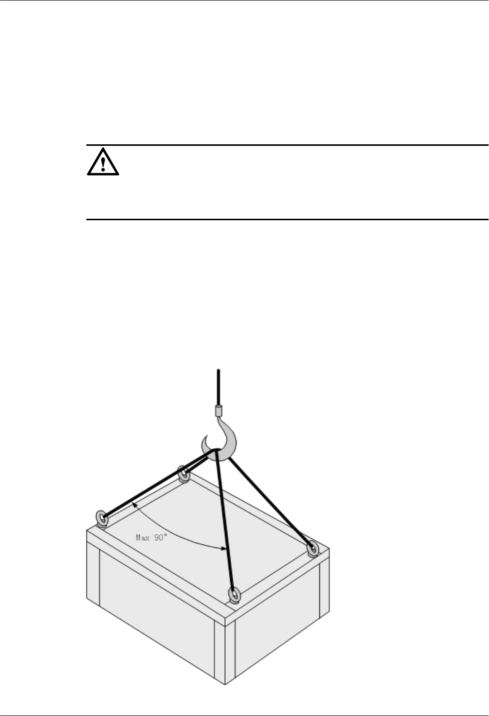
Lifting Weights
CAUTION
Do not access the areas under the arm of the crane and the goods in suspension when lifting
weights.
lEnsure that the operators have been trained and qualified.
lCheck the weight lifting tools and ensure that they are intact.
lLift the weight only when the weight lifting tools are firmly mounted onto the weight-
bearing object or the wall.
lUse a concise instruction to prevent incorrect operation.
lThe angle between the two cables should be less than or equal to 90o in the lifting of weights
(See Figure 1-2).
Figure 1-2 Lifting a weight
1 RRU3606 User Guide
Issue () Huawei Proprietary and Confidential
Copyright © Huawei Technologies Co., Ltd.
1-11
Safety Guide on Ladder Use
Checking the Ladder
lCheck the ladder before using it. Check the maximum weight that the ladder can support.
lNever overload the ladder.
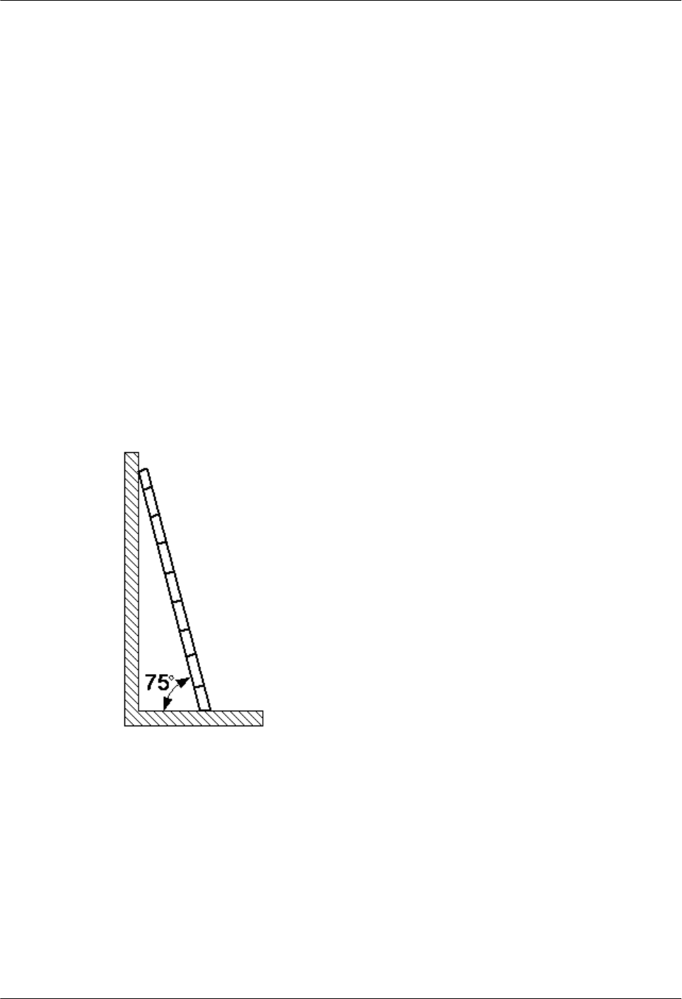
Placing the Ladder
lThe slant angle is preferred to be 75o. The slant can be measured with the angle square or
with arms, as shown in Figure 1-3. When using a ladder, place the wider end of the ladder
on the ground and take protective measures on the base of the ladder against slippage. Place
the ladder on a stable ground.
When climbing the ladder, ensure the following:
lThe gravity of the body does not shift from the edge of the ladder.
lKeep balance on the ladder before performing any operation.
lDo not climb higher than the fourth highest step of the ladder.
If you tend to climb to the roof, the length of the ladder should be at least one meter higher than
the eave, as shown in Figure 1-4.
Figure 1-3 Slant angle
1 RRU3606 User Guide
1-12 Huawei Proprietary and Confidential
Copyright © Huawei Technologies Co., Ltd.
Issue ()
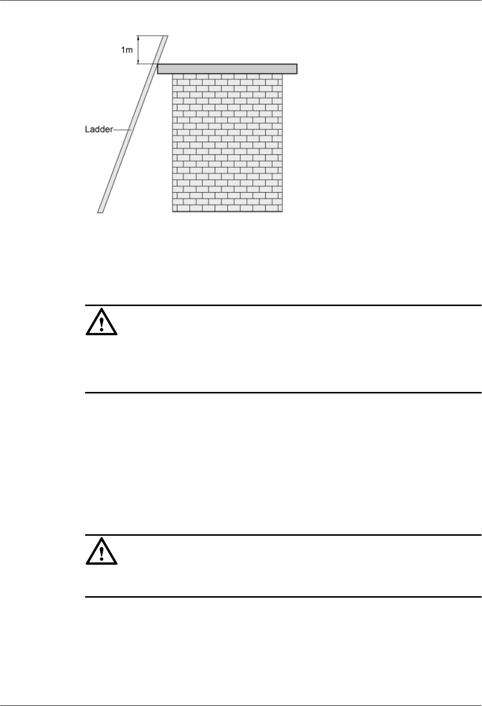
Figure 1-4 One meter higher than the eave
1.1.7 Mechanical Safety
Drilling
CAUTION
Do not drill on the cabinet without permission. Inappropriate drilling on the cabinet may damage
the electromagnetic shielding and internal cables. Metal shavings from the drilling may result
in a short-circuit of the circuit board if they get into the cabinet.
lBefore drilling a hole on the cabinet, remove the cables from the cabinet.
lDuring the drilling, wear blinkers to protect your eyes.
lDuring the drilling, wear the protective gloves.
lPrevent the metal shavings from getting into the cabinet. After drilling, clean the metal
shavings in time.
Handling Sharp Objects
CAUTION
When carrying the device by hand, wear the protective gloves to prevent injury by sharp objects.
Handling Fans
lWhen replacing a component, place the component, screw, and tool at a safe place to prevent
them from falling into the running fan.
lWhen replacing the ambient equipment around the fan, do not place the finger or board
into the running fan until the fan is switched off and stops running.
1 RRU3606 User Guide
Issue () Huawei Proprietary and Confidential
Copyright © Huawei Technologies Co., Ltd.
1-13
Moving Heavy Objects
Wear the protective gloves when moving heavy objects.
CAUTION
lBe careful when moving heavy objects.
lWhen moving the chassis outwards, be aware about the unfixed or heavy objects on the
chassis to prevent injury.
lTwo persons should be available to move a chassis; one person must not move a heavy
chassis. When moving a chassis, keep your back straight and move stably to prevent a
sprain.
lWhen moving or lifting a chassis, hold the handle or bottom of the chassis. Do not hold the
handle of the installed modules in the chassis, such as the power module, fan module, or
board.
1.1.8 Others
Inserting and Removing a Board
CAUTION
When inserting a board, wear the ESD wrist strap or gloves. Insert the board gently to prevent
any bent pins on the backplane.
lInsert the board along the guide rail.
lAvoid contact of one board with another to prevent short-circuit or damage.
lDo not remove the active board before powering off.
lWhen holding a board in hand, do not touch the board circuit, components, connectors, or
connection slots.
Bundling Signal Cables
CAUTION
Bundle the signal cables separately from the strong current cables or high voltage cables.
Cabling Requirements
At a very low temperature, movement of the cable may damage the plastic skin of the cable. To
ensure the construction safety, comply with the following requirements:
1 RRU3606 User Guide
1-14 Huawei Proprietary and Confidential
Copyright © Huawei Technologies Co., Ltd.
Issue ()

lWhen installing cables, ensure that the environment temperature is above 0oC.
lIf cables are stored in the place below 0oC, move the cables into a place at a room
temperature and store the cables for more than 24 hours before installation.
lMove the cables with care, especially at a low temperature. Do not drop the cables directly
from the vehicle.
1.2 Hardware Configuration of the RRU3606
This describes the configuration of equipment and cables of the RRU3606.
1.2.1 RRU3606
The RRU3606 transmits and receives radio signals to realize the communication between the
wireless network and the MSs.
1.2.2 RRU3606 Cables
This describes the PGND cable, power cable, CPRI optical cable, and alarm cable of the
RRU3606.
1.2.1 RRU3606
The RRU3606 transmits and receives radio signals to realize the communication between the
wireless network and the MSs.
The functions of the RRU3606 are described as follows:
lThe RRU3606 receives RF signals from the antenna system, down-converts the signals to
IF signals, and then transmits them to the BBU3900 or the macro BTS after amplification,
analog-to-digital conversion, digital down-conversion, and matched filtering.
lThe RRU3606 receives downlink baseband signals from the BBU3900 or the macro BTS,
forwards data from its cascaded RRU3606, performs filtering and data conversion, and up-
converts RF signals to meet the transmitting frequency requirements.
lThe RRU3606 multiplexes RX and TX signals over RF channels, enabling the RX signals
and TX signals to share the same antenna path. In addition, the RRU3606 filters the RX
signals and TX signals.
1.2.1.1 Appearance of the RRU3606
This describes the dimensions and appearance of the RRU3606.
1.2.1.2 Panels of the RRU3606
The RRU3606 has a bottom panel, cabling cavity panel, and indicator panel.
1.2.1.3 Physical Ports of the RRU3606
The physical ports of the RRU3606 are power supply ports, transmission ports, grounding ports,
and RF ports.
1.2.1.4 Technical Specifications of the RRU3606
This describes the technical specifications of the RRU3606.
Appearance of the RRU3606
This describes the dimensions and appearance of the RRU3606.
The dimensions of the RRU3606 are as follows:
1 RRU3606 User Guide
Issue () Huawei Proprietary and Confidential
Copyright © Huawei Technologies Co., Ltd.
1-15

lHeight x Width x Depth (without the housing) = 480 mm [18.90 in.] x 270 mm [10.63 in.]
x 140 mm [5.51 in.]
lHeight x Width x Depth (with the housing) = 488 mm [19.21 in.] x 280 mm [11.02 in.] x
155 mm [6.10 in.]
The RRU3606 features a modular structure with its ports at the bottom of the RRU3606 and on
the cabling cavity. Figure 1-5 and Figure 1-6 shows the appearance of the RRU3606.
1 RRU3606 User Guide
1-16 Huawei Proprietary and Confidential
Copyright © Huawei Technologies Co., Ltd.
Issue ()

Figure 1-5 Appearance of the RRU3606 (without the housing)
1 RRU3606 User Guide
Issue () Huawei Proprietary and Confidential
Copyright © Huawei Technologies Co., Ltd.
1-17
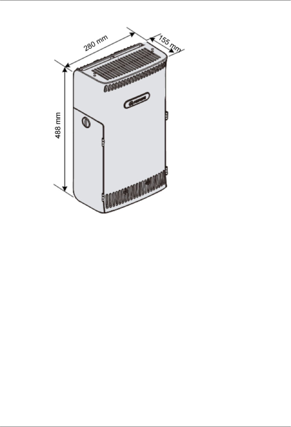
Figure 1-6 Appearance of the RRU3606 (with the housing)
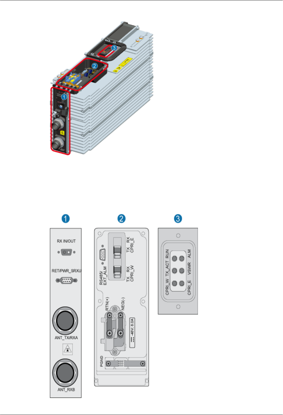
Panels of the RRU3606
The RRU3606 has a bottom panel, cabling cavity panel, and indicator panel.
Position of Panels of the RRU3606
Figure 1-7 shows the panels of the RRU3606.
1 RRU3606 User Guide
1-18 Huawei Proprietary and Confidential
Copyright © Huawei Technologies Co., Ltd.
Issue ()
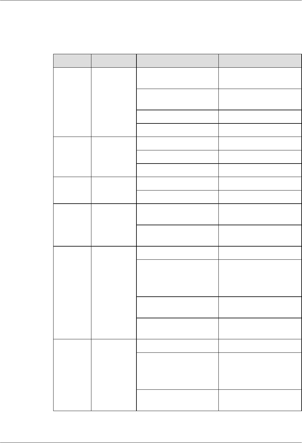
Indicators
Table 1-1 lists the indicators on the RRU3606 panel.
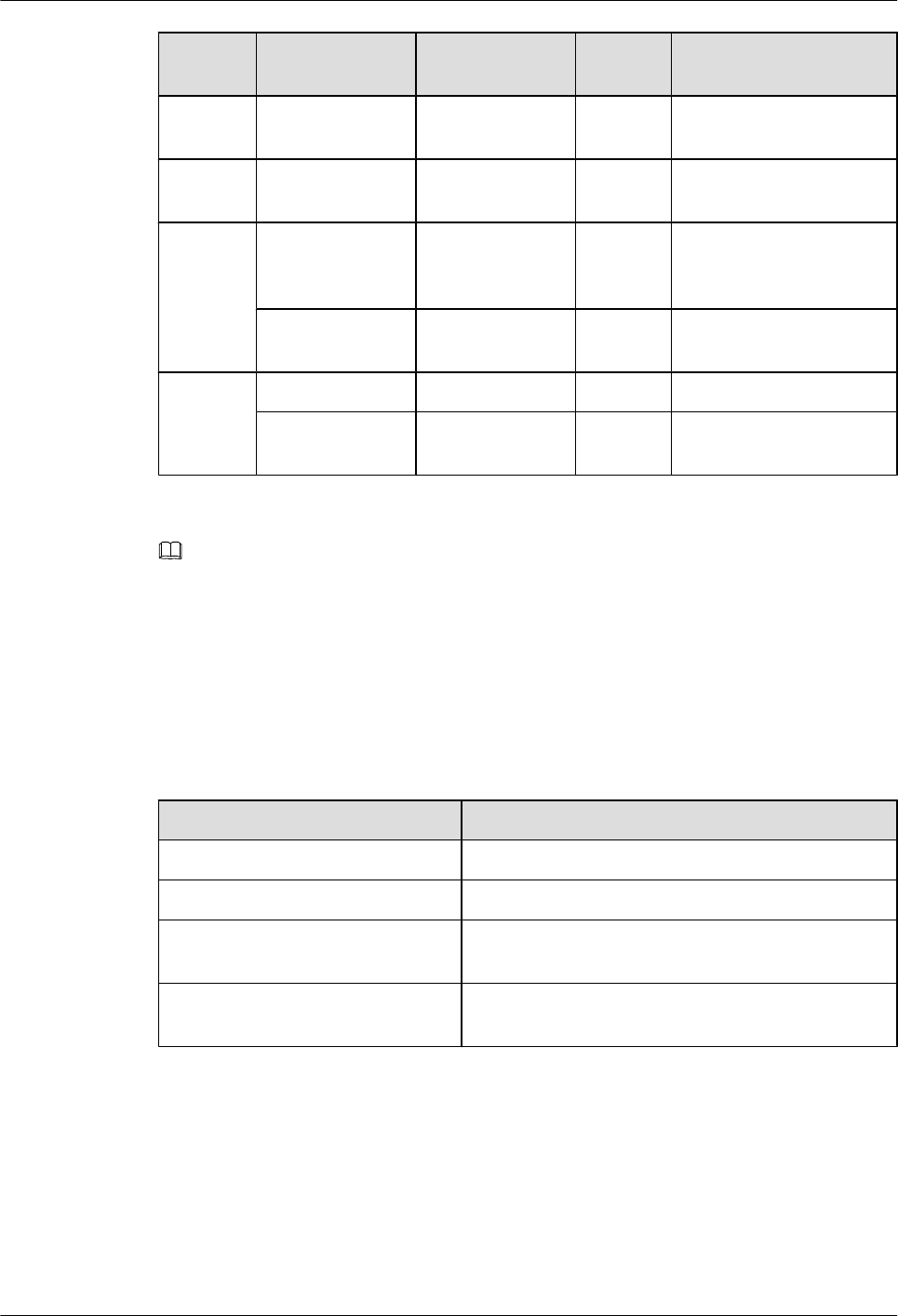
Table 1-1 Indicators on the RRU3606 panel
Mark Color Status Description
RUN Green ON The power input is normal,
but the board is faulty.
OFF There is no power input, or
alarms are generated.
ON for 1s and OFF for 1s The board operates normally.
ON for 0.5s and OFF for 0.5s Software is being loaded.
ALM Red ON Fatal alarms
Blinking at 0.5 Hz Minor alarms
OFF No alarm is generated.
TX_ACT Green ON The board operates normally.
OFF
VSWR Red ON Standing wave alarms are
generated.
OFF No standing wave alarm is
generated.
CPRI_W Red/green ON (green) The CPRI link is normal.
ON (red) The optical module receives
exceptional alarms, that is,
local alarms related to the
Loss of Signal (LOS).
ON for 0.5s and OFF for 0.5s
(red)
The CPRI link is out of lock.
OFF The optical module is not in
position or is powered off.
CPRI_E Red/green ON (green) The CPRI link is normal.
ON (red) The optical module receives
exceptional alarms, that is,
local alarms related to the
Loss of Signal (LOS).
ON for 0.5s and OFF for 0.5s
(red)
The CPRI link is out of lock.
1 RRU3606 User Guide
1-20 Huawei Proprietary and Confidential
Copyright © Huawei Technologies Co., Ltd.
Issue ()
Mark Color Status Description
OFF The optical module is not in
position or is powered off.
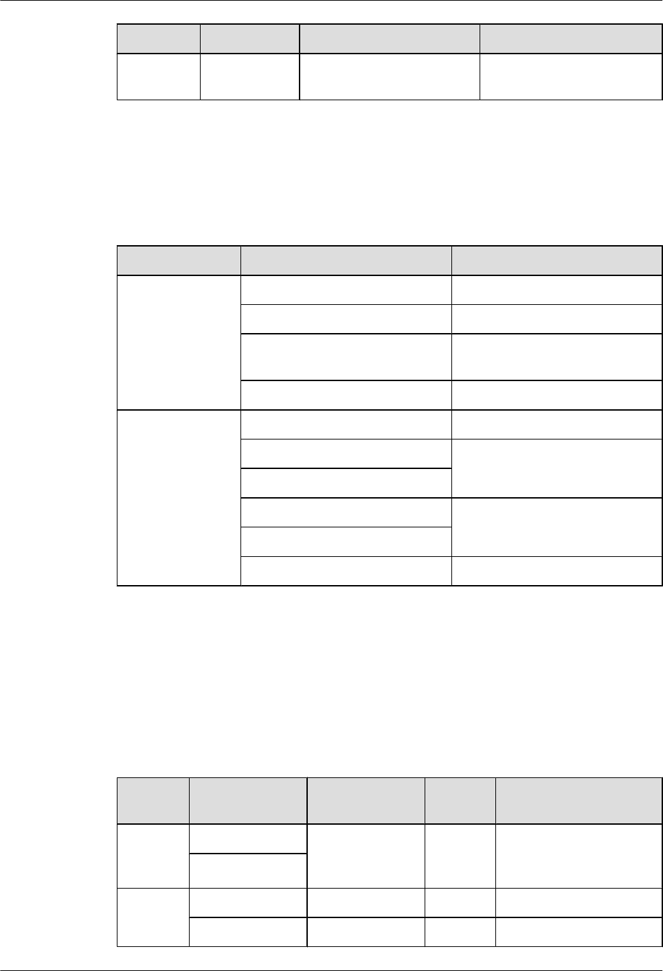
Ports
Table 1-2 lists the ports on the RRU3606 panel.
Table 1-2 Ports on the RRU3606 panel
Item Label on the Front Panel Description
Ports at the bottom RX_IN/OUT Reserved port
RET/PWR_SRXU Reserved port
ANT_TX/RXA Main RF transmitting/receiving
port
ANT_RXB Diversity RF receiving port
Ports on the
cabling cavity
RS485/EXT_ALM Alarms port
CPRI_E CPRI ports
CPRI_W
RTN(+) Power supply ports
NEG(-)
PGND PGND crimp piece
Physical Ports of the RRU3606
The physical ports of the RRU3606 are power supply ports, transmission ports, grounding ports,
and RF ports.
Table 1-3 lists the physical ports of the RRU3606.
Table 1-3 Physical ports of the RRU3606
Type Port Description Quantit
y
Connector Type
Power
supply
ports
RTN(+) -48 V DC power
supply
1 OT terminal
NEG(-)
Transmis
sion ports
CPRI_E CPRI ports 1 ESFP socket
CPRI_W CPRI ports 1 ESFP socket
1 RRU3606 User Guide
Issue () Huawei Proprietary and Confidential
Copyright © Huawei Technologies Co., Ltd.
1-21
Type Port Description Quantit
y
Connector Type
Alarms
port
RS485/
EXT_ALM
RS485 x1 signal
port
1 DB15
Groundin
g port
- - 4 -
RF port ANT_TX/RXA Main
transmitting/
receiving port
1 Round and waterproof
DIN connector
ANT_RXB Diversity
receiving port
1 Round and waterproof
DIN connector
Reserved
port
RX_IN/OUT Reserved - -
RET/
PWR_SRXU
Reserved - -
NOTE
The specifications for the RRU3606 alarm port are: 0.2 kohm for the closed resistance; 51 kohms for the
open resistance.
Technical Specifications of the RRU3606
This describes the technical specifications of the RRU3606.
Table 1-4 lists the specifications of the RRU3606.
Table 1-4 Technical specifications of the RRU3606
Item Specification
Voltage -48 V (-37 V DC to -60 V DC)
Power consumption ≤ 300 W
Weight The weight of the RRU3606 and housing is no more
than 17.5 kg [38.58 lb.].
Cabinet dimensions (height x width
x depth)
Height x Width x Depth (with the housing): 488 mm
[19.21 in.] x 280 mm [11.02 in.] x 155 mm [6.10 in.]
1.2.2 RRU3606 Cables
This describes the PGND cable, power cable, CPRI optical cable, and alarm cable of the
RRU3606.
1.2.2.1 PGND Cable of the RRU3606
The PGND cable ensures the grounding of the RRU3606.
1 RRU3606 User Guide
1-22 Huawei Proprietary and Confidential
Copyright © Huawei Technologies Co., Ltd.
Issue ()
1.2.2.2 Power Cable of the RRU3606
This describes the power cable of the RRU3606. The -48 V DC power cable feeds external -48
V DC power to the RRU3606 to provide power supply for the RRU3606.
1.2.2.3 RRU3606 Optical Fibers
RRU3606 optical fibers are used for the connection between the BBU3900 and the RRU3606.
1.2.2.4 Alarm Cable of the RRU3606
The alarm cable leads one RS485 alarm signal from external devices to the RRU3606, thus
monitoring the external devices.
PGND Cable of the RRU3606
The PGND cable ensures the grounding of the RRU3606.
Structure
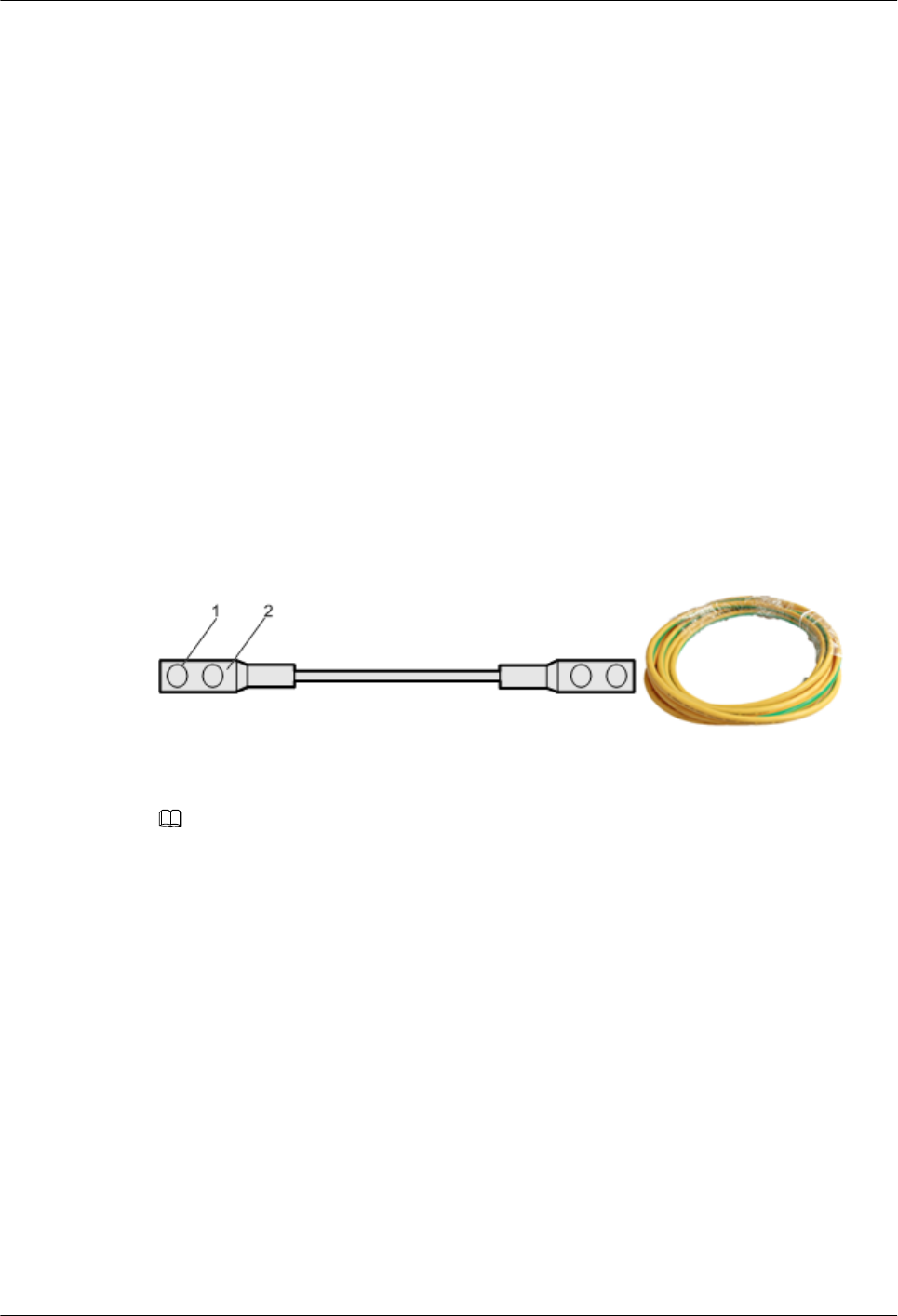
The green and yellow PGND cable has a cross-sectional area of 16 mm2 [0.02 in.2]. Both ends
of the cable are 2-hole OT terminals. If the PGND cable is provided by the customer, a copper-
core cable with a minimum cross-sectional area of 16 mm2 [0.02 in.2] is recommended.
Figure 1-9 shows the structure of the PGND cable.
Figure 1-9 Structure of the PGND cable
(1) 2-hole OT terminal (2) Heat shrink tube
NOTE
lThe OT terminals of the grounding cable are made on site.
lThe color of the PGND cable is selected according to the local specifications.
Position of the Cable
For the PGND cable of the RRU3606, one end is connected to the grounding hole on the
RRU3606, and the other end is connected to the ground nearby. Figure 1-10 shows the
connections of the PGND cables.
1 RRU3606 User Guide
Issue () Huawei Proprietary and Confidential
Copyright © Huawei Technologies Co., Ltd.
1-23
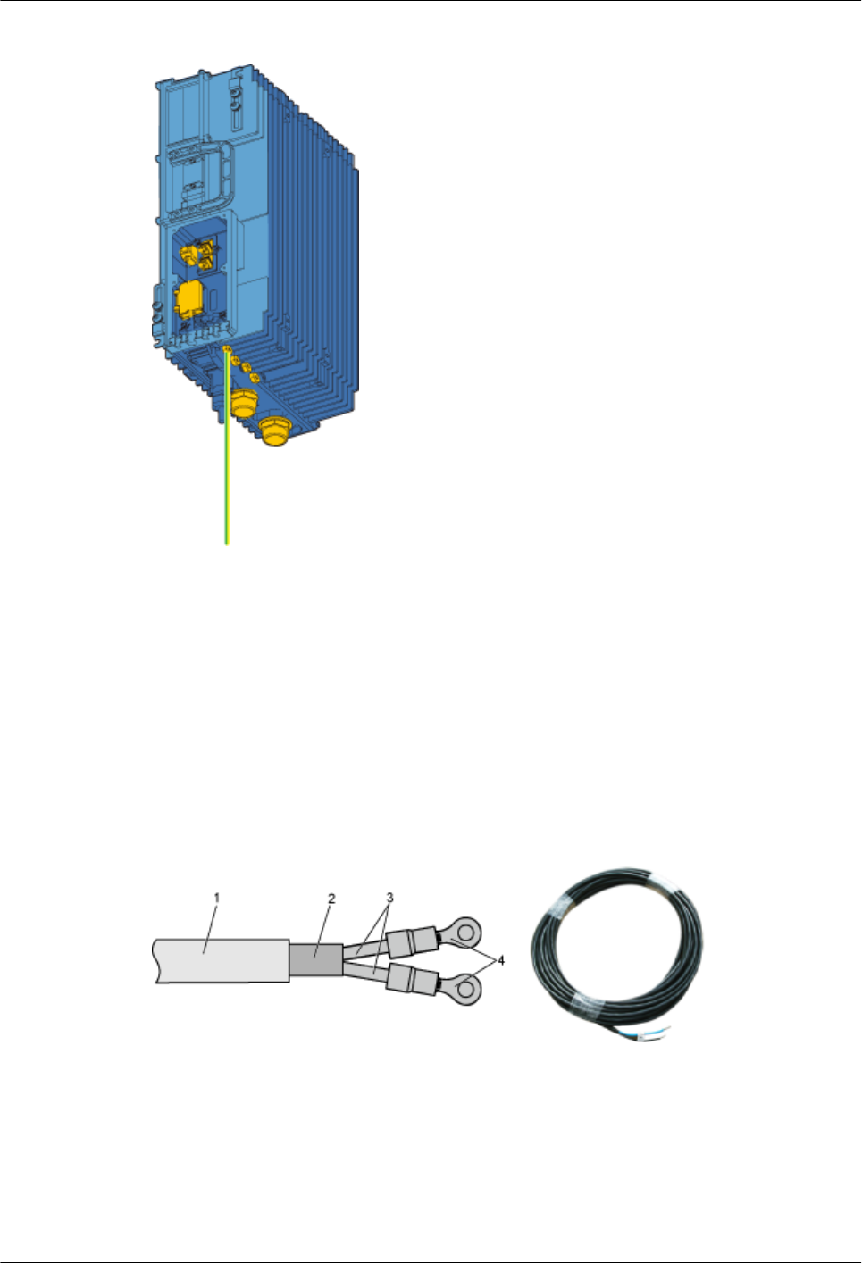
Figure 1-10 Installation position of the PGND cable
Power Cable of the RRU3606
This describes the power cable of the RRU3606. The -48 V DC power cable feeds external -48
V DC power to the RRU3606 to provide power supply for the RRU3606.
Structure
The RRU3606 uses the -48 V DC shielded power cable. One end of the cable has two OT
terminals, and the other end is bare. Figure 1-11 shows the power cable of the RRU3606.
Figure 1-11 Structure of the -48 V DC power cable
(1) -48 V DC power cable (2) Shielding layer (3) Wire (4) OT terminal
Cable Specifications
The -48 V DC cable is a 2-wire cable, as shown in Table 1-5 and Table 1-6.
1 RRU3606 User Guide
1-24 Huawei Proprietary and Confidential
Copyright © Huawei Technologies Co., Ltd.
Issue ()
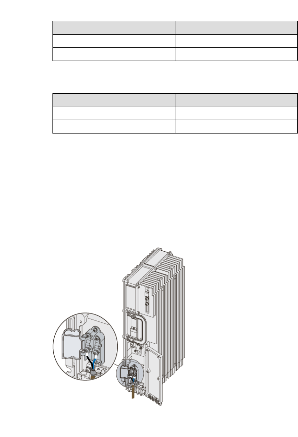
Table 1-5 Pin assignment of the -48 V DC power cable (standard in North America)
Name Color
NEG cable Blue
RTN cable Black
Table 1-6 Pin assignment of the -48 V DC power cable (standard in Europe)
Name Color
NEG cable Blue
RTN cable Brown
Position of the Cable
Connect the OT terminal of the blue wire of the -48 V DC power cable to the NEG (-) port on
the RRU3606 cabling cavity, and connect the black or brown wire to the RTN (+) port of the
RRU3606.
Connect the other end of the -48 V DC power cable to the power supply system at the installation
site.
Figure 1-12 shows the installation position of the power cable on the RRU3606 side.
Figure 1-12 Installation of the power cable on the RRU3606 side
1 RRU3606 User Guide
Issue () Huawei Proprietary and Confidential
Copyright © Huawei Technologies Co., Ltd.
1-25
RRU3606 Optical Fibers
RRU3606 optical fibers are used for the connection between the BBU3900 and the RRU3606.
Structure
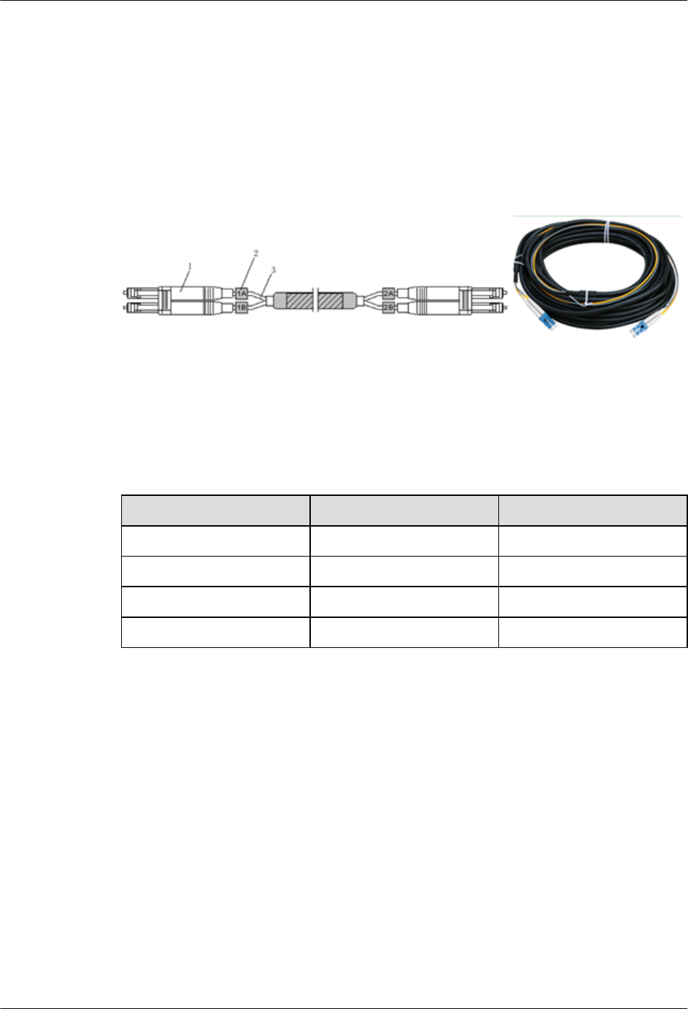
The CPRI optical cable is a multi-mode 2-wire cable with LC connectors at both ends. Figure
1-13 shows the CPRT optical fiber.
Figure 1-13 Structure of the CPRI optical fiber
(1) DLC connector (2) Label (3) Fiber tail
Cable
Table 1-7 describes the pin assignment for the fiber tails.
Table 1-7 Pin assignment for the fiber tails
Label Color Connection Position
1A Orange RX port on the RRU3606
1B Gray TX port on the RRU3606
2A Orange TX port on the BBU3900
2B Gray RX port on the BBU3900
Position of the Cable
One end of the CPRI optical fiber is connected to the SFP port of the BBU3900 or to the ODF,
and the other end is connected to the CPRI optical port of the RRU3606. Figure 1-14 shows the
installation position of the CPRI optical fiber on the RRU3606 side.
1 RRU3606 User Guide
1-26 Huawei Proprietary and Confidential
Copyright © Huawei Technologies Co., Ltd.
Issue ()
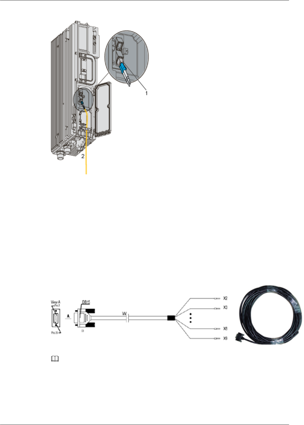
Figure 1-14 Structure of the CPRI optical cable
(1) Pluggable optical modules (2) To the BBU3900 or the ODF
Alarm Cable of the RRU3606
The alarm cable leads one RS485 alarm signal from external devices to the RRU3606, thus
monitoring the external devices.
Structure
One end of the alarm cable is a DB15 female connector, and the other end has 8 cord end
terminals, as shown in Figure 1-15.
Figure 1-15 Structure of the alarm cable of the RRU3606
NOTE
If the connector of the alarm cable and the port of the alarm device do not match, remove the cord end
terminals. Prepare the connector on site based on the port type of the alarm device.
Cable
The alarm cable supports one RS485 alarm signal. Table 1-8 lists the pin assignment for the
wires of the RRU3606.
1 RRU3606 User Guide
Issue () Huawei Proprietary and Confidential
Copyright © Huawei Technologies Co., Ltd.
1-27
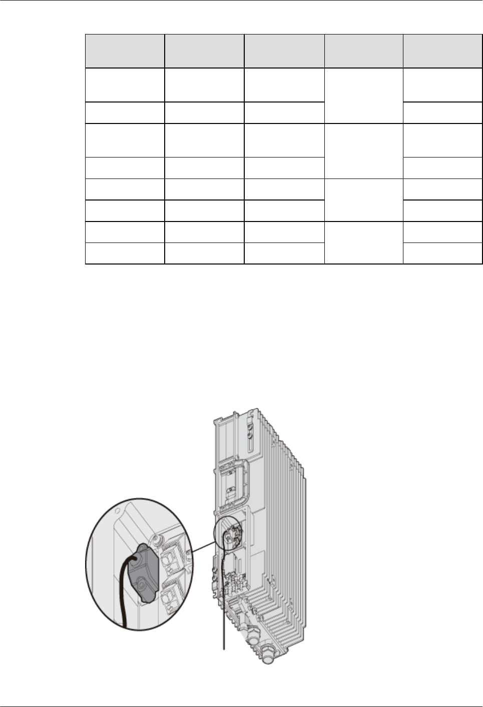
Table 1-8 Alarm cable of the RRU3606
X1 Pin Cord End
Terminal
Wire Color Wire Type Label
X1.2 X2 White/blue Twisted pair
cable
SWITCH_INP
UT0+
X1.3 X3 Blue GND
X1.6 X4 White/orange Twisted pair
cable
SWITCH_INP
UT1+
X1.7 X5 Orange GND
X1.10 X6 White/green Twisted pair
cable
RS485_TX-
X1.11 X7 Green RS485_TX+
X1.13 X8 White/brown Twisted pair
cable
RS485_RX-
X1.14 X9 Brown RS485_RX+
Position of the Cable
The DB15 male connector of the alarm cable is connected to the RS485/EXT_ALM port on the
RRU3606 cabling cavity, and the other end is connected to the port for Boolean alarm signals
on the external device. Figure 1-16 shows the installation position of the alarm cable on the
RRU3606 side.
Figure 1-16 Installation of the alarm cable on the RRU3606 side
1 RRU3606 User Guide
1-28 Huawei Proprietary and Confidential
Copyright © Huawei Technologies Co., Ltd.
Issue ()

1.3 Installing Hardware for the RRU3606
This describes the hardware installation, cable distribution, and installation checklist for the
RRU3606.
1.3.1 Installation Information of the RRU3606
This describes the installation modes, requirements for the installation space and cable
distribution, and connections of the cables.
1.3.2 Process of Installing the RRU3606
This describes the installation preparation, installation of the RRU3606, cables, and housing,
and hardware installation check.
1.3.3 Preparations for RRU3606 Installation
This describes the installation tools and the unpacking inspection of the equipment.
1.3.4 Installing the RRU3606
This describes the installation modes for a single RRU3606, two RRU3606s, and three
RRU3606s.
1.3.5 Installing and Removing the Cables of the RRU3606
This describes how to install and remove the cables of the RRU3606 and how to install the cover
of the cabling cavity of the RRU3606.
1.3.6 Powering On the RRU3606
This describes how to power on the RRU3606.
1.3.7 Installing the Shell of the RRU3606
This describes how to install the shell of the RRU3606.
1.3.8 Checklist for the Installation of the RRU3606
This describes the items to be checked after the RRU3606 is installed.
1.3.1 Installation Information of the RRU3606
This describes the installation modes, requirements for the installation space and cable
distribution, and connections of the cables.
1.3.1.1 Installation Modes of the RRU3606
This describes the installation modes of the RRU3606. The RRU3606 can be installed on the
metal pole, wire pole, and wall.
1.3.1.2 Requirements for the Installation Space of the RRU3606s
This describes the requirements for the installation space of a single RRU3606, combination of
RRU3606s, and centralized installation of RRU3606s.
1.3.1.3 Requirements for Routing Cables of the RRU3606
This describes the requirements for routing cables of the RRU3606 to prevent electromagnetic
interference.
1.3.1.4 Connection of the RRU3606 Cables
This describes the connection of the cables of a single RRU3606 and multiple RRU3606s.
1 RRU3606 User Guide
Issue () Huawei Proprietary and Confidential
Copyright © Huawei Technologies Co., Ltd.
1-29
Installation Modes of the RRU3606
This describes the installation modes of the RRU3606. The RRU3606 can be installed on the
metal pole, wire pole, and wall.
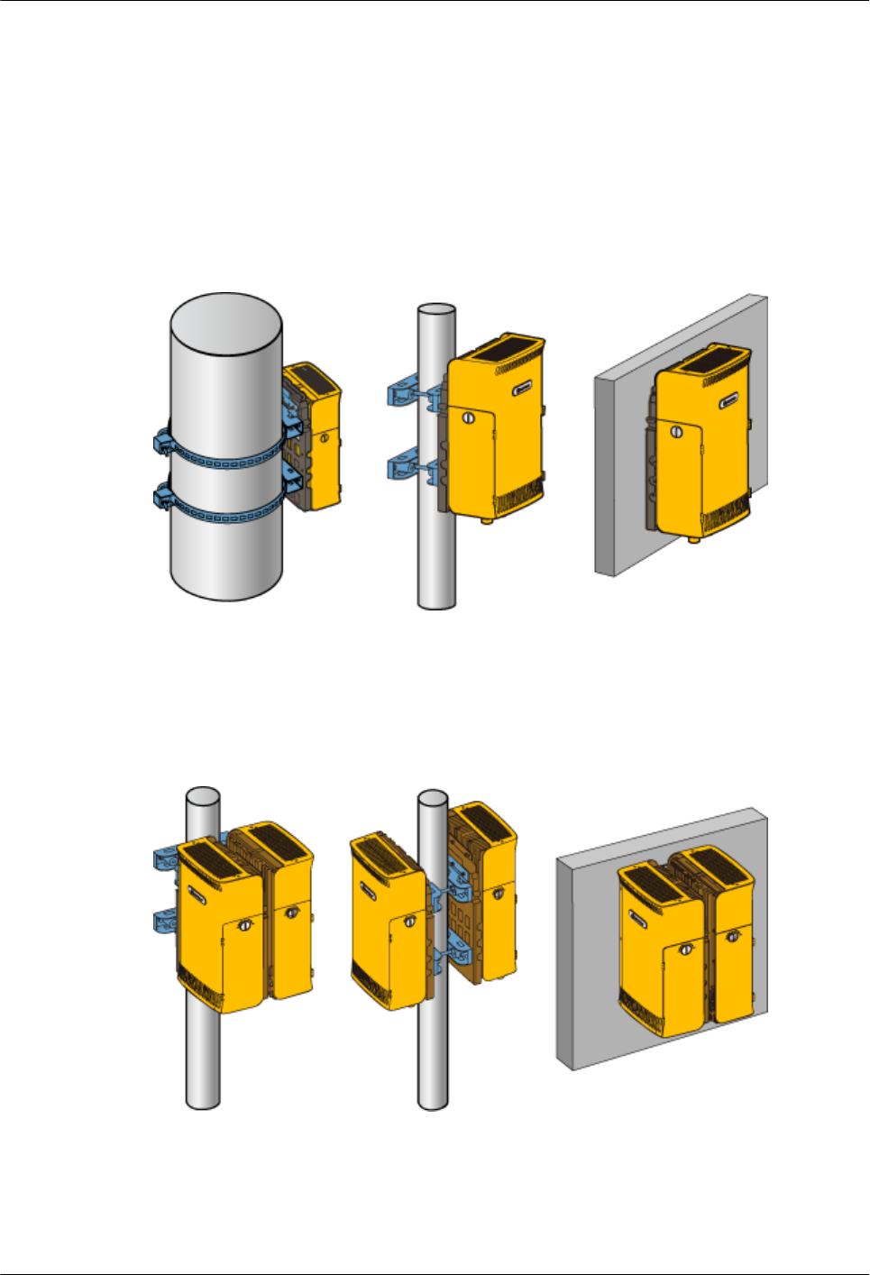
Installation Mode of A Single RRU3606
Figure 1-17 shows the installation mode of a single RRU3606.
Figure 1-17 Installation of a single RRU3606
Centralized Installation Mode of Two RRU3606s
Figure 1-18 shows the centralized installation mode of two RRU3606s.
Figure 1-18 Centralized installation of two RRU3606s
Centralized Installation Mode of Three RRU3606s
Figure 1-19 shows the installation mode of three RRU3606s.
1 RRU3606 User Guide
1-30 Huawei Proprietary and Confidential
Copyright © Huawei Technologies Co., Ltd.
Issue ()
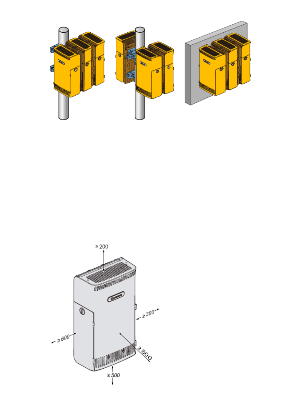
Figure 1-19 Centralized installation of three RRU3606s
Requirements for the Installation Space of the RRU3606s
This describes the requirements for the installation space of a single RRU3606, combination of
RRU3606s, and centralized installation of RRU3606s.
Specific requirements for the installation space of the RRU3606 should be met to facilitate
cabling, operation, and maintenance. The requirements described in this document are based on
engineering experience.
Requirements for the Installation Space of a Single RRU3606
Figure 1-20 shows the requirements for the installation space of a single RRU3606.
Figure 1-20 Installation space (mm) of a single RRU3606
The requirements for the installation space of a single RRU3606 are as follows:
1 RRU3606 User Guide
Issue () Huawei Proprietary and Confidential
Copyright © Huawei Technologies Co., Ltd.
1-31

lUnder the RRU3606, a distance of at least 500 mm [19.69 in.] should be reserved for
cabling. For convenient maintenance, it is recommended that the distance between the
bottom of the RRU3606 and the ground be at least 1200 mm [47.24 in.].
lIn front of the RRU3606, a space of at least 800 mm [31.50 in.] should be reserved for
maintenance.
lAbove the RRU3606, a space of at least 200 mm [7.87 in.] should be reserved for
maintenance.
lTo the left of the RRU3606, a space of at least 600 mm [23.62 in.] should be reserved for
maintenance.
lTo the right of the RRU3606, a space of at least 300 mm [11.81 in.] should be reserved for
maintenance.
Requirements for the minimum installation space of a single RRU3606 are as follows:
lUnder the RRU3606, a space of at least 300 mm [11.81 in.] should be reserved for cabling.
For convenient maintenance, it is recommended that the distance between the bottom of
the RRU3606 and the ground be at least 1200 mm [47.24 in.].
lIn front of the RRU3606, a space of at least 600 mm [23.62 in.] should be reserved for
maintenance.
lAbove the RRU3606, a space of at least 200 mm [7.87 in.] should be reserved for
maintenance.
lTo the left of the RRU3606, a space of at least 400 mm [15.75 in.] should be reserved for
maintenance.
lTo the right of the RRU3606, a space of at least 100 mm [3.94 in.] should be reserved for
maintenance.
Requirements for the Installation Space of Combined RRU3606s
During the combination of RRU3606s, ensure that the installation space reserved for each
RRU3606 meets the requirements. Figure 1-21 shows the requirement for the distance between
two single RRU3606s.
1 RRU3606 User Guide
1-32 Huawei Proprietary and Confidential
Copyright © Huawei Technologies Co., Ltd.
Issue ()
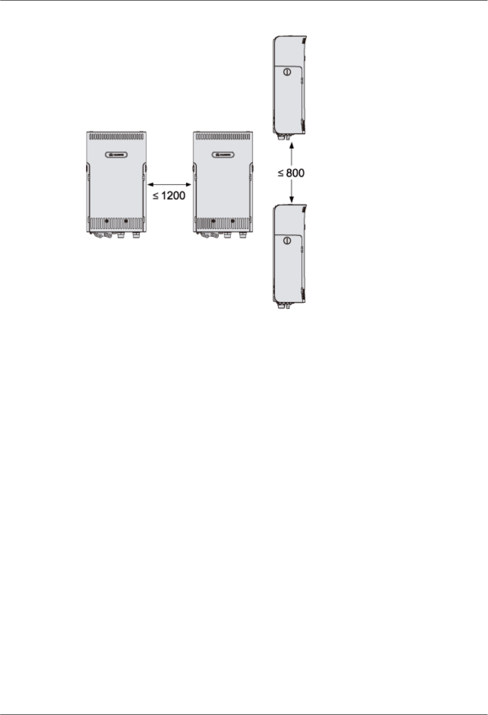
Figure 1-21 Distance between two single RRU3606s (unit: mm)
The requirements for the distance between two single RRU3606s are as follows:
lThe distance between one RRU3606 and the one to its left or right is no more than 1200
mm [47.24 in.].
lThe distance between one RRU3606 and the one above or below is no more than 800 mm
[31.50 in.].
Requirements for the Centralized Installation Space of RRU3606s
Figure 1-22 shows the requirements for the installation space of multiple RRU3606s.
1 RRU3606 User Guide
Issue () Huawei Proprietary and Confidential
Copyright © Huawei Technologies Co., Ltd.
1-33
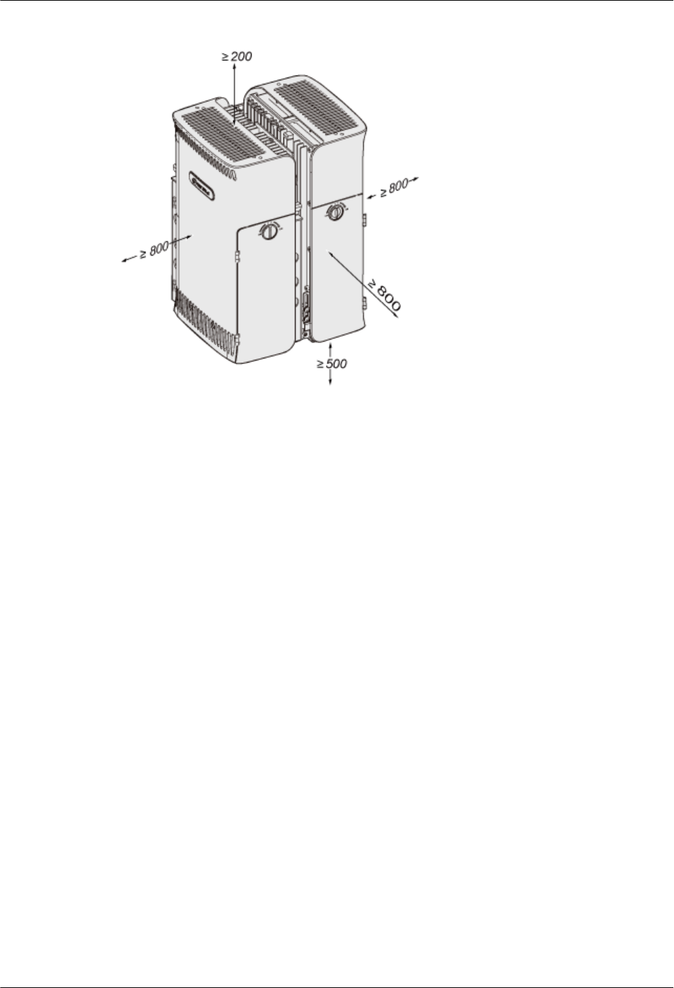
Figure 1-22 Centralized installation space of RRU3606s (unit: mm)
Requirements for the centralized installation space of RRU3606s are as follows:
lUnder the RRU3606, at least 500 mm [19.69 in.] space should be reserved for cabling. For
convenient maintenance, it is recommended that the distance between the bottom of the
RRU3606 and the ground be at least 1200 mm [47.24 in.].
lIn front of the RRU3606, a space of at least 800 mm [31.50 in.] should be reserved for
maintenance.
lAbove the RRU3606, a space of at least 200 mm [7.87 in.] should be reserved for
maintenance.
lTo the left of the RRU3606, a space of at least 800 mm [31.50 in.] should be reserved for
maintenance.
lTo the right of the RRU3606, a space of at least 800 mm [31.50 in.] should be reserved for
maintenance.
lThe requirements for the installation space of two or three RRU3606s are identical.
Requirements for the minimum centralized installation space of RRU3606s are as follows:
lUnder the RRU3606, at least 300 mm [11.81 in.] space should be reserved for cabling. For
convenient maintenance, it is recommended that the distance between the bottom of the
RRU3606 and the ground be at least 1200 mm [47.24 in.].
lIn front of the RRU3606, a space of at least 600 mm [23.62 in.] should be reserved for
maintenance.
lAbove the RRU3606, a space of at least 200 mm [7.87 in.] should be reserved for
maintenance.
lTo the left of the RRU3606, a space of at least 600 mm [23.62 in.] should be reserved for
maintenance.
lTo the right of the RRU3606, a space of at least 600 mm [23.62 in.] should be reserved for
maintenance.
1 RRU3606 User Guide
1-34 Huawei Proprietary and Confidential
Copyright © Huawei Technologies Co., Ltd.
Issue ()

Requirements for Routing Cables of the RRU3606
This describes the requirements for routing cables of the RRU3606 to prevent electromagnetic
interference.
Requirements for routing cables of the RRU3606 are as follows:
lThe positions of power cables should meet the specifications of engineering drawings and
the standards of general cabling.
lDifferent types of cable should be routed separately to prevent cables from twisting.
lAfter all the cables are installed, stick labels or bind tokens to the cables.
lThe bending radius of optical fibers should be no less than 20 times the diameter of the
optical fiber.
lLeave some margin at the bending parts of the optical fibers.
lWhen installing the optical fibers, do not step on or stretch them too tight. Take care to
prevent the optical fibers from touching sharp objects. If the main body of the fiber has
bend marks or press marks and the connectors are damaged, the optical fiber cannot be
used any more.
lThe minimum bending radius of the feeder should be no less than 20 times the diameter of
the feeder.
lThe feeder has no obvious bend or twist marks or bare copper core wires.
lThe connectors of feeders are made in compliance with specifications and connected
correctly. Make sure the feeders do not loosen up.
lEnsure that the two ends of the grounding cables are in good contact and anti-corrosion
treated.
Connection of the RRU3606 Cables
This describes the connection of the cables of a single RRU3606 and multiple RRU3606s.
Connection of the Cables of A Single RRU3606
Figure 1-23 shows the connection of the cables of a single RRU3606.
1 RRU3606 User Guide
Issue () Huawei Proprietary and Confidential
Copyright © Huawei Technologies Co., Ltd.
1-35
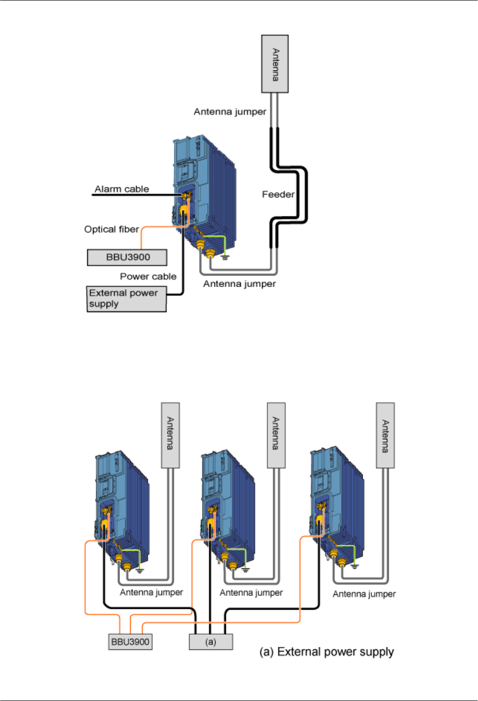
Figure 1-23 Connection of the cables of a single RRU3606
Connection of the Cables of Multiple RRU3606s
Figure 1-24 shows the connection of the cables of multiple RRU3606s.
Figure 1-24 Connection of the cables of multiple RRU3606s
1 RRU3606 User Guide
1-36 Huawei Proprietary and Confidential
Copyright © Huawei Technologies Co., Ltd.
Issue ()

1.3.2 Process of Installing the RRU3606
This describes the installation preparation, installation of the RRU3606, cables, and housing,
and hardware installation check.
Background Information
NOTE
For the following situations, contact Huawei engineers for confirmation.
lYou provide the devices, cables, and connectors yourself.
lYou need to cut a cable of a specified length.
Procedure
Step 1 Unpack and inspect the equipment and the required tools for installation. For details, refer to
1.3.3 Preparations for RRU3606 Installation.
Step 2 Install the backplanes and the RRU3606. Choose an appropriate installation mode according to
the installation scenario. For details on the installation modes, see:
l1.3.4.1 Installing a Single RRU3606
l1.3.4.2 Installing Two RRU3606s in Centralized Mode
l1.3.4.3 Installing Three RRU3606s in Centralized Mode
Step 3 Perform the operations described in 1.3.5 Installing and Removing the Cables of the
RRU3606.
Step 4 Perform the operations described in 1.3.6 Powering On the RRU3606.
Step 5 Perform the operations described in 1.3.7 Installing the Shell of the RRU3606.
Step 6 Perform the operations described in 1.3.8 Checklist for the Installation of the RRU3606.
----End
1.3.3 Preparations for RRU3606 Installation
This describes the installation tools and the unpacking inspection of the equipment.
1.3.3.1 Installation Tools for the RRU3606
This describes the general tools, dedicated tools, and instruments for RRU3606 installation.
1.3.3.2 Unpacking Inspection for the RRU3606
Before installing the equipment, unpack the equipment package and check the equipment.
Installation Tools for the RRU3606
This describes the general tools, dedicated tools, and instruments for RRU3606 installation.
Table 1-9 lists the tools and instruments required for the installation.
1 RRU3606 User Guide
Issue () Huawei Proprietary and Confidential
Copyright © Huawei Technologies Co., Ltd.
1-37
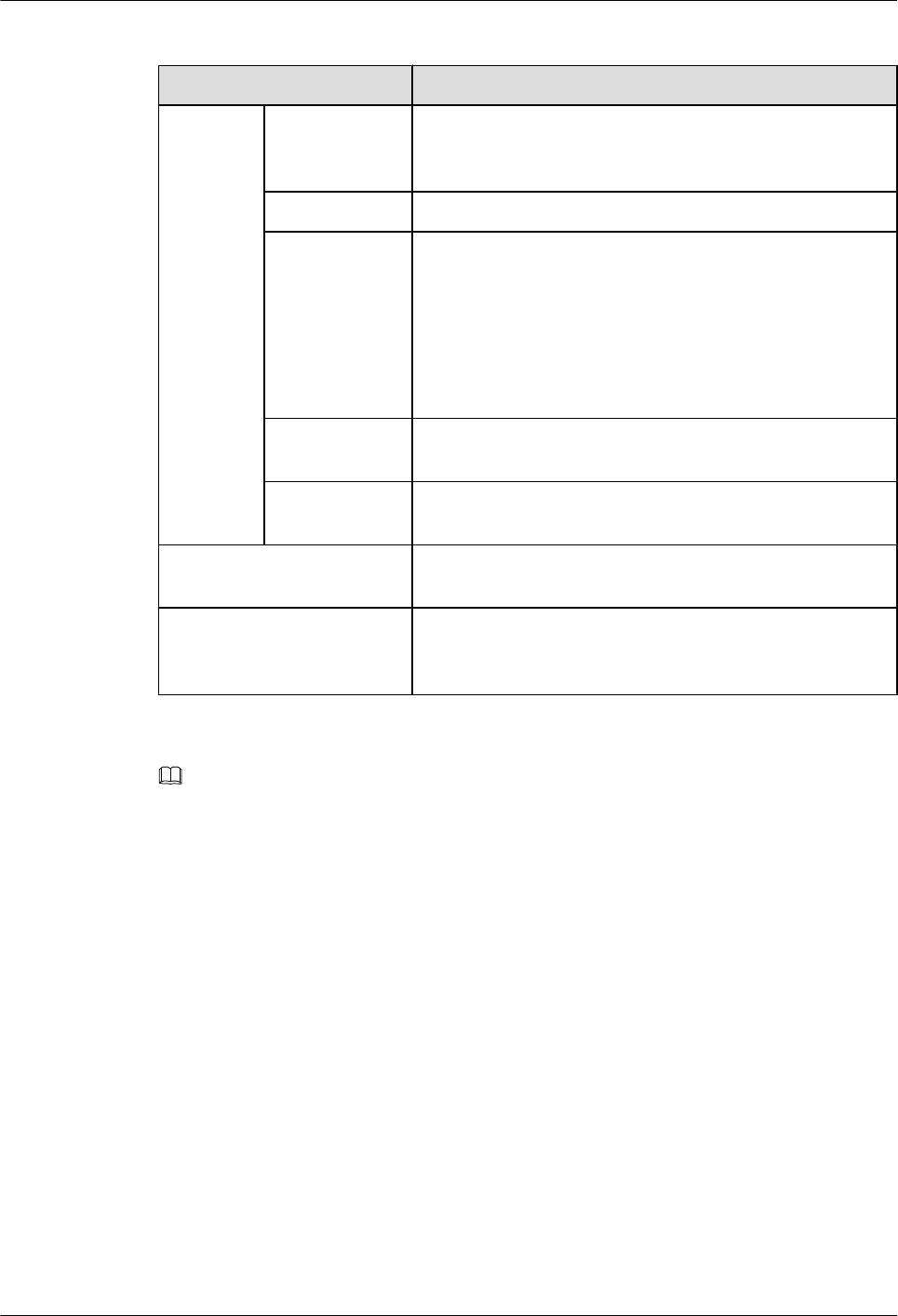
Table 1-9 Tools and instruments
Category List of the Tools
General
tools
Measuring and
marking
instruments
Long tape, ruler (1 m [3.28 ft.]), level instrument, marker,
powder marker, and pencil
Drilling Tools One percussion drill, matched drill bits, and one cleaner
Fastening tools Straight screwdrivers: M3–M6
Cross screwdrivers: M3–M6
Adjustable wrench
Socket wrenches: M6, M8, M12, M14, M17, and M19
Double offset ring spanners: M6, M8, M12, M14, M17, and
M19
Small tools Sharp-nose pliers, diagonal pliers, pliers, hand-held electric
drill, file, handsaw, crowbar, and rubber hammer
Auxiliary tools Brush, nipper, paper knife, bellows, electric irons, solder
wire, fork, and ladders
Dedicated tools Multimeter, 500 V megohm meter (for testing the insulation
resistance), BER tester, and optical power meter
Instruments Earth resistance tester, antistatic wrist strap, antistatic
gloves, cable peeler, crimping pliers, RJ45 connector
crimping pliers, optical connector, and wire punchdown tool
NOTE
lThe tool list is provided by Huawei, and the tool provider is determined through negotiation.
lThe instruments must be calibrated to ensure measurement accuracy.
Unpacking Inspection for the RRU3606
Before installing the equipment, unpack the equipment package and check the equipment.
Context
The requirements for unpacking inspection are as follows:
lBoth the project supervisor and customer representatives must be present to check the
goods.
lWhen unpacking goods, ensure that the total number of products is consistent with the
packing list attached to the packing case, the arrival place is the installation site, the packing
case is in good condition, and the cabinet is not placed upside down.
lDo not unpack if the outer package is damaged or wet, or the equipment is wet and rusty.
Find the cause of the damage and report to the Huawei regional office.
1 RRU3606 User Guide
1-38 Huawei Proprietary and Confidential
Copyright © Huawei Technologies Co., Ltd.
Issue ()
CAUTION
To protect the equipment and find out the cause, move the unpacked equipment indoor for
proper storage, and take photos of the storage site, rusty or corroded equipment, packing
cases, and packaging materials. Keep these photos and store the unpacked packing cases
and packaging materials.
lIf the products are in good condition, unpack the packing case with a label marked "Built-
in Packing List", take out the packing list, and then check the products according to the
packing list. If any of the products are damaged or missing, fill in the Cargo Replacement
Application Form.
lAfter the unpacking inspection, sign the packing list together with the customer.
CAUTION
lWhen transporting or moving the equipment, components, or parts, prevent them from
colliding with doors, walls, or shelves.
lDo not touch the uncoated surface of the equipment, parts, or components when you wear
sweat soaked or dirty gloves.
Unpacking Wooden Cases
A wooden case is usually made of wooden boards, steel edges, tongues, and foamed angle wraps.
Move the packing case into the equipment room to avoid damage to the equipment during the
transportation.
The process of unpacking inspection for the wooden cases is as follows:
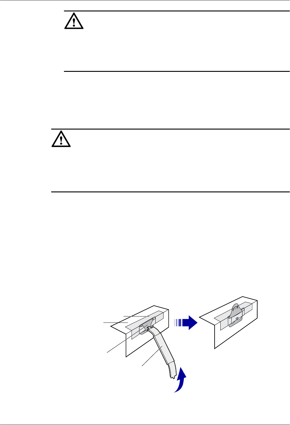
1. Insert the spanner into the hole of the tongue and turn the ejector lever to straighten the
tongue, as shown in Figure 1-25.
Figure 1-25 Straightening the tongue
Spanner
Tongue
Woodenboard
Steeledge
2. Straighten all the tongues that fix the cover, and then remove the cover, as shown in Figure
1-26.
1 RRU3606 User Guide
Issue () Huawei Proprietary and Confidential
Copyright © Huawei Technologies Co., Ltd.
1-39
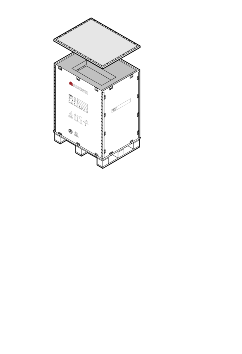
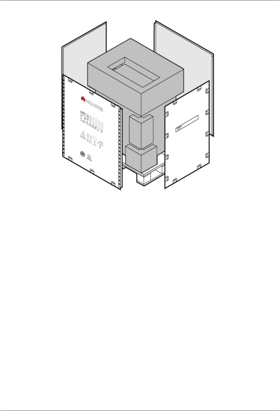
Figure 1-27 Removing side boards
Unpacking Inspection for Cartons
Cartons are usually used to pack cables, circuit boards, and terminal devices.
The process of the unpacking inspection for cartons is as follows:
1. Check the types and number of boards in the carton according to the label on the carton.
2. Cut the straps using diagonal pliers.
3. Cut the tapes along the seams of the carton cover. Do not insert the knife too deep.
Otherwise, the goods inside may be scratched.
4. Open the carton and take out the foam plate.
5. Check the number of board boxes according to the label on the carton.
6. Check the quantities and types of materials according to the Packing List, and sign on the
list if the quantities and types are correct.
1.3.4 Installing the RRU3606
This describes the installation modes for a single RRU3606, two RRU3606s, and three
RRU3606s.
1.3.4.1 Installing a Single RRU3606
This describes the installation of a single RRU3606 on a metal pole, wire pole, or wall.
1.3.4.2 Installing Two RRU3606s in Centralized Mode
This describes how to install two RRU3606s in centralized mode. You can install two RRU3606s
on a metal pole or wall.
1.3.4.3 Installing Three RRU3606s in Centralized Mode
1 RRU3606 User Guide
Issue () Huawei Proprietary and Confidential
Copyright © Huawei Technologies Co., Ltd.
1-41

This describes how to install three RRU3606s in centralized mode. You can install three
RRU3606s on a metal pole or wall.
Installing a Single RRU3606
This describes the installation of a single RRU3606 on a metal pole, wire pole, or wall.
1.3.4.1.1 Installing the Backplane of a Single RRU3606 on a Metal Pole
This describes how to install the backplane of a single RRU3606 on a metal pole.
1.3.4.1.2 Installing the Backplane of a Single RRU3606 on a Wire Pole
This describes how to install the backplane of a single RRU3606 on a wire pole.
1.3.4.1.3 Installing the Backplane of a Single RRU3606 on the Wall
This describes how to install the backplane of a single RRU3606 on the wall.
1.3.4.1.4 Installing a Single RRU3606
This describes how to install a single RR3606 on a metal pole. The procedures for installing the
RRU3606 on the backplane in different scenarios are the same.
1. Installing the Backplane of a Single RRU3606 on a Metal Pole
This describes how to install the backplane of a single RRU3606 on a metal pole.
Prerequisite
A metal pole whose diameter is 60 mm [2.36 in.] to 110 mm [4.33 in.] is available.
Procedure
Step 1 Determine the installation position of the backplane on the metal pole according to the
construction drawing and 1.3.1.2 Requirements for the Installation Space of the
RRU3606s.
NOTE
The height for installing the fixtures on the metal pole ranges from 1200 mm [47.24 in.] to 1600 mm [62.99
in.].
Step 2 Mount the fixtures on the metal pole and ensure that the two fixtures are level on the horizontal
plane, as shown in Figure 1-28.
1 RRU3606 User Guide
1-42 Huawei Proprietary and Confidential
Copyright © Huawei Technologies Co., Ltd.
Issue ()
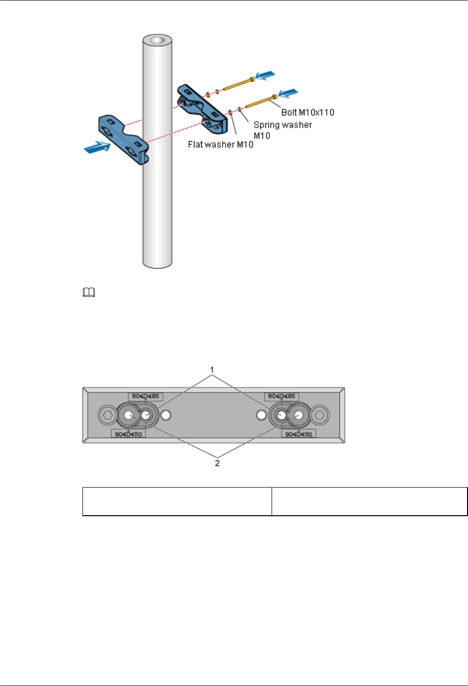
Figure 1-28 Installing the upper fixtures
NOTE
There are two sets of installation holes for fixing the fixtures. The installation holes on the inside fit 60
mm [2.36 in.] into 95 mm [3.74 in.] bolts, and the installation holes on the outside fit 90 mm [3.54 in.] into
110 mm [4.33 in.] bolts, as shown in Figure 1-29.
Figure 1-29 Installation holes for fixing fixtures
(1) Installation holes on the inside (2) Installation holes on the outside
Step 3 Use a level bar to adjust the level of the fixtures.
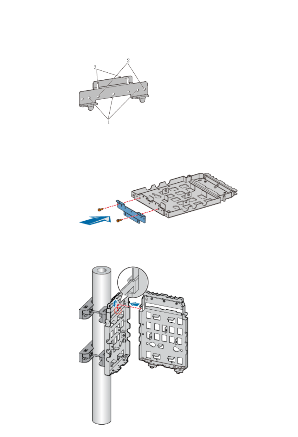
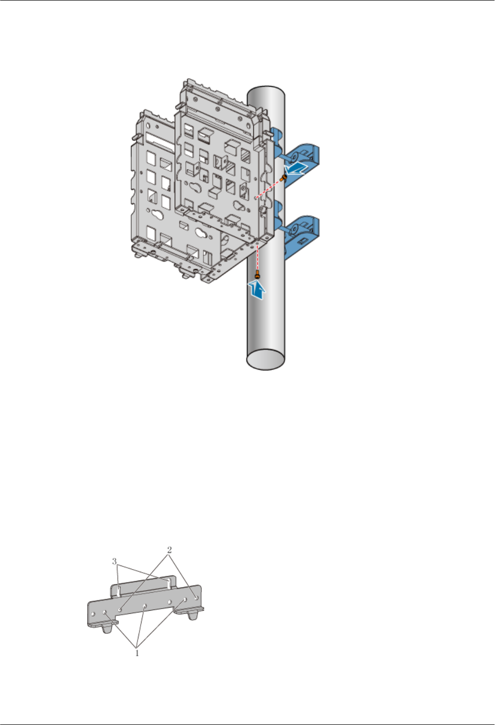
Step 4 Choose the installation holes marked 1 for general mounting brackets, as shown in Figure
1-30.
1 RRU3606 User Guide
Issue () Huawei Proprietary and Confidential
Copyright © Huawei Technologies Co., Ltd.
1-43
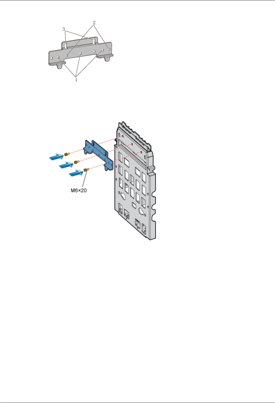
Figure 1-30 Choosing installation holes for mounting brackets
Step 5 Install the general mounting bracket into the installation hole at the rear of the backplane by
using three M6x20 bolts, as shown in Figure 1-31.
Figure 1-31 Installing general mounting brackets
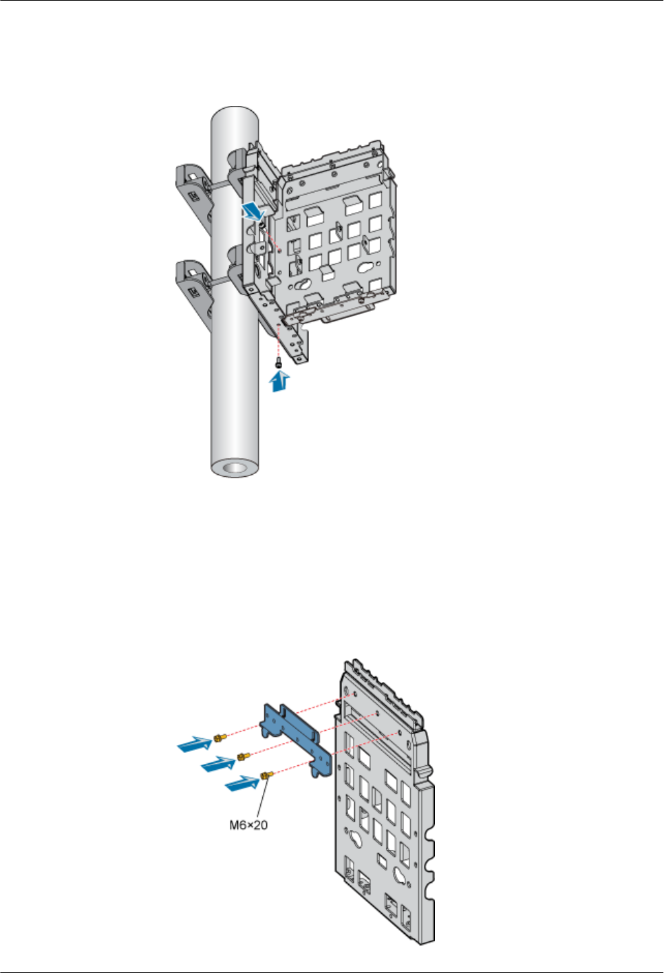
Step 6 Install the fixtures into the upper installation hole at the rear of the backplane through two
M10x40 bolts, as shown in Figure 1-32.
1 RRU3606 User Guide
1-44 Huawei Proprietary and Confidential
Copyright © Huawei Technologies Co., Ltd.
Issue ()
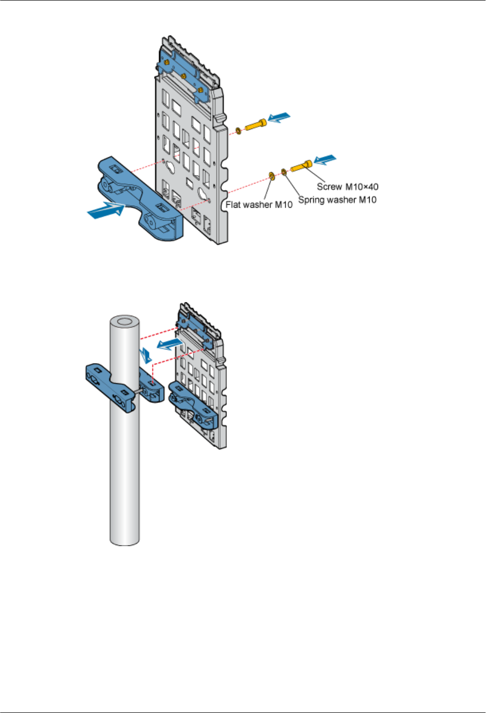
Figure 1-32 Installing the fixtures at the rear of the backplane
Step 7 Mount the backplane to the fixture of the metal pole, as shown in Figure 1-33.
Figure 1-33 Mounting the backplane
Step 8 Fasten the fixture to the fixtures that are installed at the lower part of the backplane of the metal
pole through two M10x110 bolts, as shown in Figure 1-34.
1 RRU3606 User Guide
Issue () Huawei Proprietary and Confidential
Copyright © Huawei Technologies Co., Ltd.
1-45
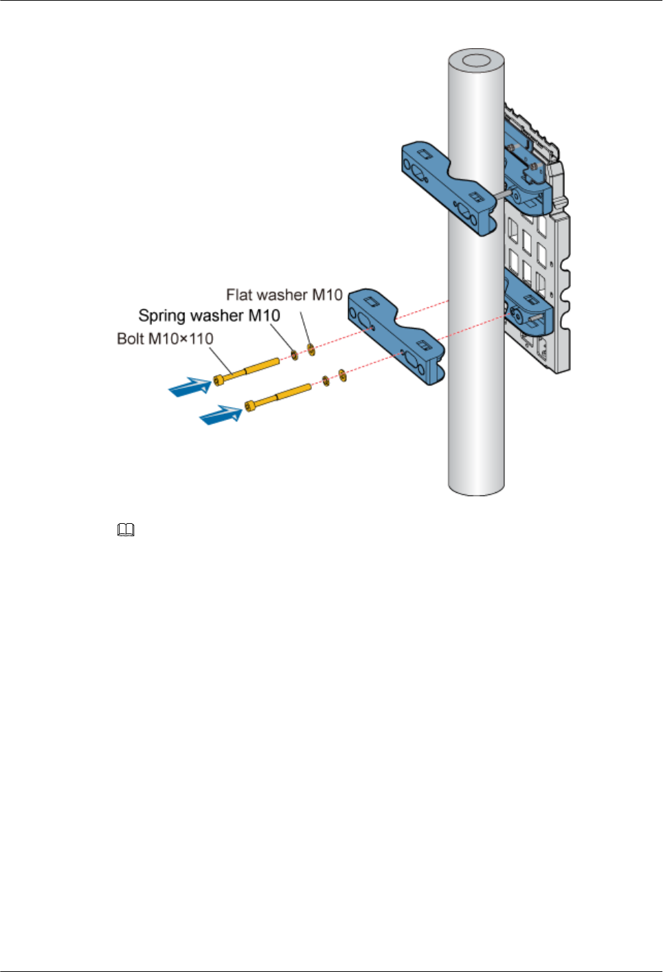
Figure 1-34 Fastening the lower fixtures
NOTE
There are two sets of installation holes for fixing the fixtures. The installation holes on the inside are
provided for 60 mm [2.36 in.] to 95 mm [3.74 in.] bolts, and the installation holes on the outside are provided
for 90 mm [3.54 in.] to 110 mm [4.33 in.] bolts, as shown in Figure 1-29.
----End
2. Installing the Backplane of a Single RRU3606 on a Wire Pole
This describes how to install the backplane of a single RRU3606 on a wire pole.
Prerequisite
A wire pole whose diameter is 30.48 cm [12 in.] to 38.1 cm [15 in.] is available.
Procedure
Step 1 Determine the installation position of the backplane on the wire pole according to the
construction drawing and 1.3.1.2 Requirements for the Installation Space of the
RRU3606s.
Step 2 Insert the bundling tape through fixtures. Figure 1-35 shows the required fixtures.
1 RRU3606 User Guide
1-46 Huawei Proprietary and Confidential
Copyright © Huawei Technologies Co., Ltd.
Issue ()
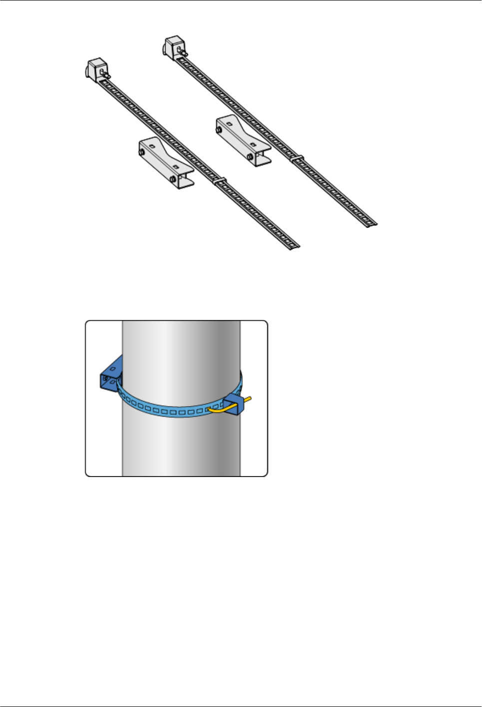
Figure 1-35 Installing the fixtures on a wire pole
Step 3 Clasp the tightening hook to a proper square hole of the bundling tape in the installation position
on the wire pole, as shown in Figure 1-36.
Figure 1-36 Installing the bundling tape
Step 4 Use a wrench to tighten the nut until the bundling tape is fastened around the wire pole, as shown
in Figure 1-37.
1 RRU3606 User Guide
Issue () Huawei Proprietary and Confidential
Copyright © Huawei Technologies Co., Ltd.
1-47
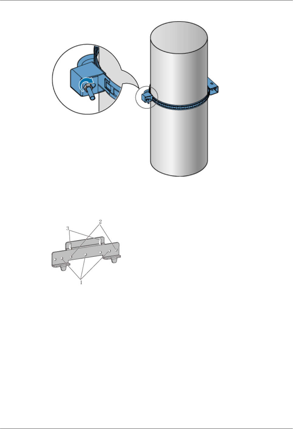
Figure 1-37 Tightening the bundling tape
Step 5 Choose the installation holes marked 1 for general mounting brackets, as shown in Figure
1-38.
Figure 1-38 Choosing installation holes for mounting brackets
Step 6 Install the general mounting bracket into the installation hole at the rear of the backplane through
three M6 x 20 bolts, as shown in Figure 1-39.
1 RRU3606 User Guide
1-48 Huawei Proprietary and Confidential
Copyright © Huawei Technologies Co., Ltd.
Issue ()
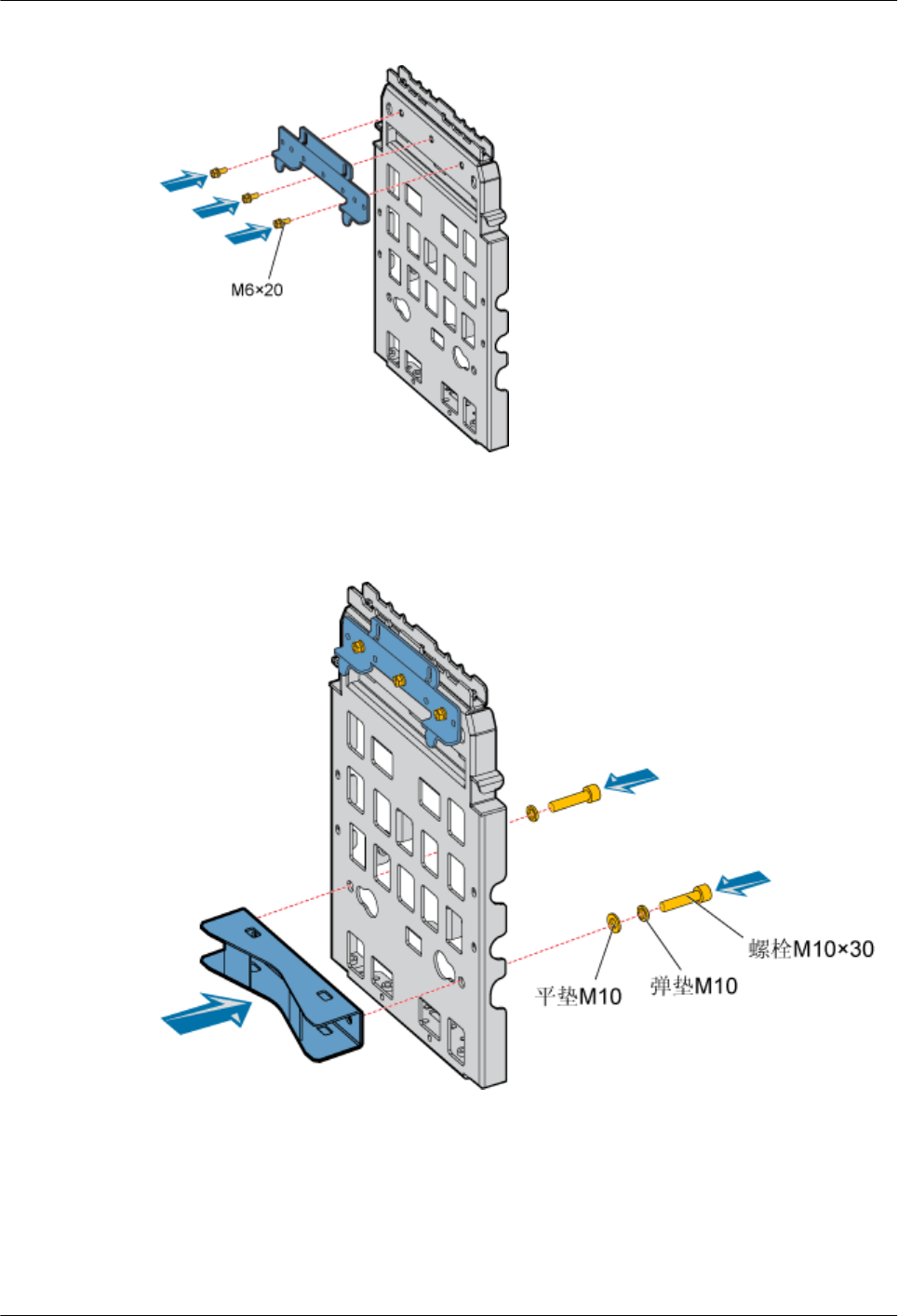
Figure 1-39 Installing general mounting brackets
Step 7 Install the fixtures in the upper installation hole at the rear of the backplane through two M10 x
30 bolts, as shown in Figure 1-40.
Figure 1-40 Installing the fixtures at the rear of the backplane
Step 8 Mount the backplane to the fixture of the metal pole, as shown in Figure 1-41.
1 RRU3606 User Guide
Issue () Huawei Proprietary and Confidential
Copyright © Huawei Technologies Co., Ltd.
1-49
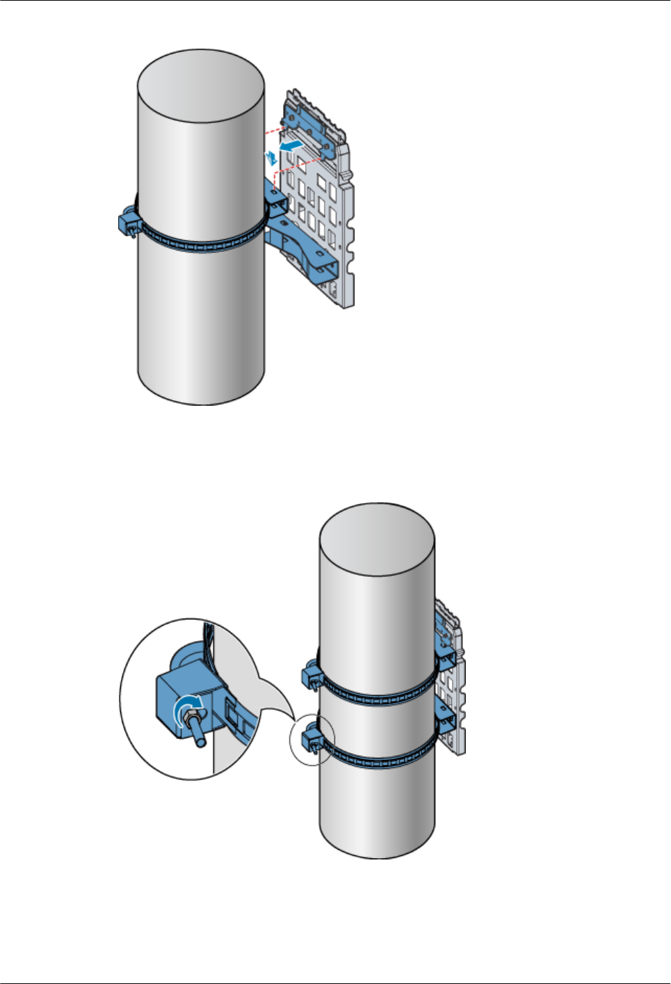
Figure 1-41 Mounting the backplane
Step 9 Use the bundling tape to fasten the fixtures at the lower part of the backplane on the wire pole,
as shown in Figure 1-42.
Figure 1-42 Fastening the backplane through the bundling tape
----End
3. Installing the Backplane of a Single RRU3606 on the Wall
This describes how to install the backplane of a single RRU3606 on the wall.
1 RRU3606 User Guide
1-50 Huawei Proprietary and Confidential
Copyright © Huawei Technologies Co., Ltd.
Issue ()
Procedure
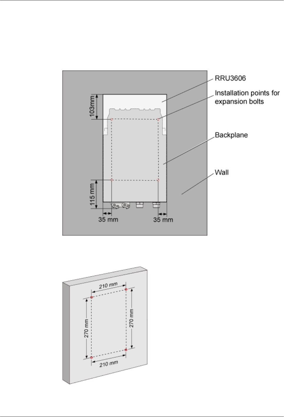
Step 1 Determine the installation position on the wall for a single RRU3606.
1. Determine the position on the backplane of the RRU3606 for installing the expansion bolts,
as shown in Figure 1-43.
Figure 1-43 Installing the expansion bolts on the backplane
2. Determine the installation holes on the wall, as shown in Figure 1-44.
Figure 1-44 Installation holes on the wall
1 RRU3606 User Guide
Issue () Huawei Proprietary and Confidential
Copyright © Huawei Technologies Co., Ltd.
1-51
NOTE
lThe height for installing the RRU3606 on the wall ranges from 1200 mm [47.24 in.] to 1600 mm
[62.99 in.].
lPlace the backplane against the wall and use a marking pen to mark the anchor points. You can
also mark the anchor points according to the inter-hole distance.
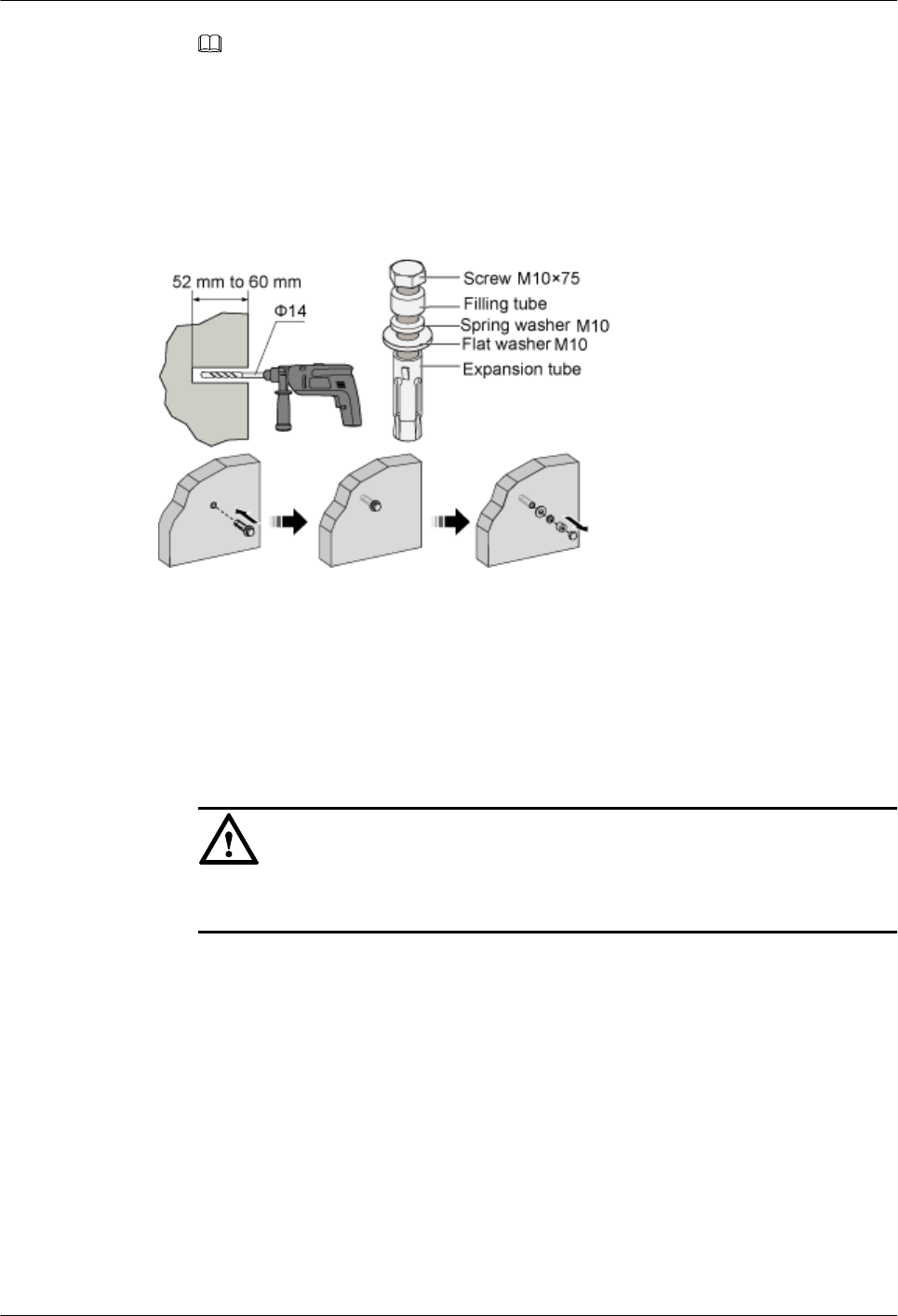
Step 2 Drill holes on the marks and install the expansion bolts, as shown in Figure 1-45.
Figure 1-45 Drilling holes and installing expansion bolts
1. Use a percussion drill with a φ14 drill bit to drill holes on the marks. The depth of the holes
ranges from 52 mm [2.05 in.] to 60 mm [2.36 in.].
2. Use a cleaner to clear the dust inside and around the holes. If the inter-hole distance is too
long or too short, locate and drill holes again.
3. Tighten slightly the expansion bolt and feed it into the hole vertically. Use a rubber hammer
to hit the expansion tube until it is fully buried in the wall.
4. Remove the M10x75 bolt, filling tube, spring washer M10, and flat washer M10.
CAUTION
Dissemble the expansion bolt, and ensure that the expansion tube is fully buried in the wall.
Otherwise, the backplane is placed unevenly.
Step 3 Fix the backplane, as shown in Figure 1-46.
1 RRU3606 User Guide
1-52 Huawei Proprietary and Confidential
Copyright © Huawei Technologies Co., Ltd.
Issue ()
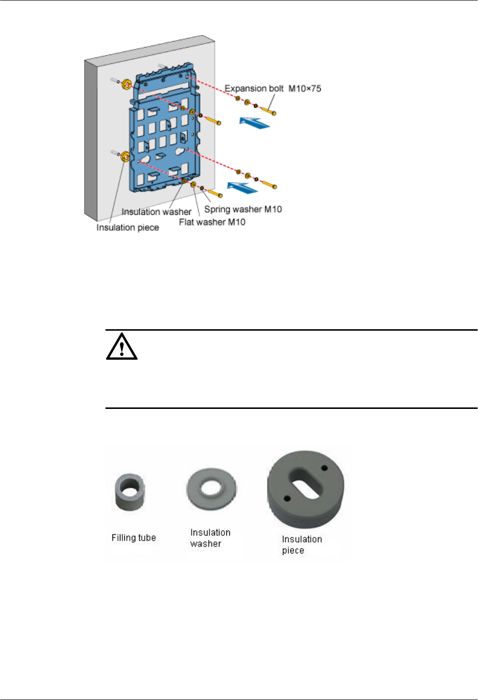
Figure 1-46 Fixing the backplane
1. Place the backplane in the installation position against the wall.
2. Get ready four M10x75 bolts, fit the M10 spring washer, M10 flat washer, and insulation
washer into each of the bolt, and then fasten the assembled bolts into the nut of the expansion
tube across the holes on the backplane and insulation plate.
CAUTION
When installing the bolts, remove the filling tube of the expansion bolt through the
insulation washer and insulation plate that are delivered with the backplane, as shown in
Figure 1-47.
Figure 1-47 Filling tube, insulation washer, and insulation plate
Step 4 Use a wrench to rotate the M10x75 bolt clockwise and tighten the expansion bolt to fix the
backplane on the wall.
----End
4. Installing a Single RRU3606
This describes how to install a single RR3606 on a metal pole. The procedures for installing the
RRU3606 on the backplane in different scenarios are the same.
1 RRU3606 User Guide
Issue () Huawei Proprietary and Confidential
Copyright © Huawei Technologies Co., Ltd.
1-53
Prerequisite
lThe backplane of the RRU3606 is already installed.
lIf the RRU3606 is to be installed on a metal pole, the grounding protection cable of the
metal pole is already correctly connected.
Installation Instructions
The RRU3606 can be installed in two modes. In one mode, the back of the RRU3606 touches
the backplane (front mode); in the other mode, the front of the RRU3606 touches the backplane
(rear mode). This document takes the installation of the RRU3606 on the metal pole as an
example to illustrate the front and back installation modes of the RRU3606, as shown in Figure
1-48.
Figure 1-48 Front and back installation modes of the RRU3606
NOTE
lThe RRU3606 has a plastic shell. In Figure 1-48, the plastic shell is removed so that you can clearly
see the front and back installation modes.
lBy default, the plastic shell is installed for the RRU3606 in front installation mode.
Procedure
Step 1 Use two M6x20 screws to fix the mounting bracket to the RRU3606, as shown in Figure
1-49.
1 RRU3606 User Guide
1-54 Huawei Proprietary and Confidential
Copyright © Huawei Technologies Co., Ltd.
Issue ()
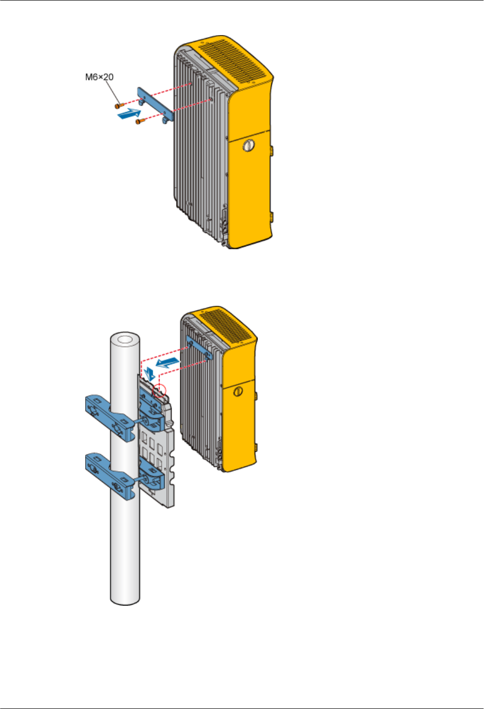
Figure 1-49 Fixing the mounting bracket
Step 2 Fit the hooks of the mounting bracket into the slots of the backplane, as shown in Figure 1-50.
Figure 1-50 Installing the RRU3606
Step 3 Use two M6x20 screws to fix the RRU3606 to the backplane through the installation holes at
the bottom of the backplane, as shown in Figure 1-51.
1 RRU3606 User Guide
Issue () Huawei Proprietary and Confidential
Copyright © Huawei Technologies Co., Ltd.
1-55
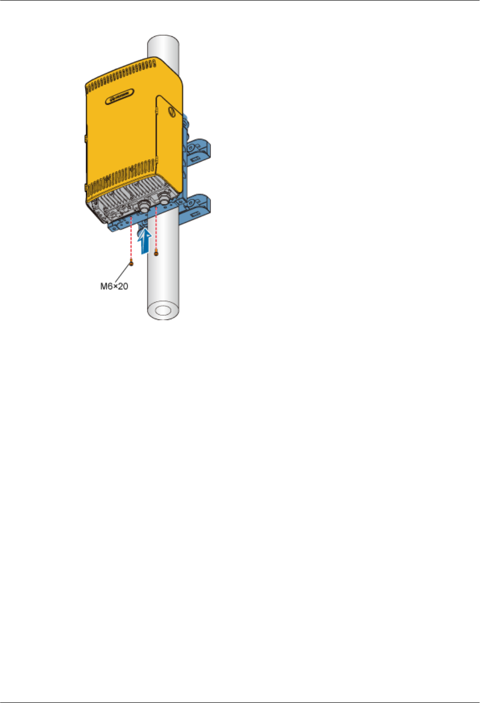
Figure 1-51 Fixing the RRU3606
----End
Installing Two RRU3606s in Centralized Mode
This describes how to install two RRU3606s in centralized mode. You can install two RRU3606s
on a metal pole or wall.
1.3.4.2.1 Installing the Backplanes of Two RRU3606s on the Metal Pole
This describes how to install the backplanes of two RRU3606s on the metal pole.
1.3.4.2.2 Installing the Backplanes of Two RRU3606s on the Wall
This describes how to install the backplanes of two RRU3606s on the wall.
1.3.4.2.3 Installing Two RRU3606s in Centralized Mode
This describes how to install two RRU3606s in centralized mode. In different scenarios, the
procedures for installing two RRU3606s on the backplanes are the same. This document takes
the pole installation scenario as an example.
1. Installing the Backplanes of Two RRU3606s on the Metal Pole
This describes how to install the backplanes of two RRU3606s on the metal pole.
Prerequisite
A metal pole whose diameter is 60 mm [2.36 in.] to 110 mm [4.33 in.] is available.
Installation Instructions
You can install two RRU3606s on the metal pole in either of the following modes:
1 RRU3606 User Guide
1-56 Huawei Proprietary and Confidential
Copyright © Huawei Technologies Co., Ltd.
Issue ()

lSide-by-side mode
lBack-to-back mode
Figure 1-52 shows the top view of the RRU3606s installed in side-by-side mode.
Figure 1-52 Top view of the RRU3606s installed in side-by-side mode
Figure 1-53 shows the top view of the RRU3606s installed in back-to-back mode.
Figure 1-53 Top view of the RRU3606s installed in back-to-back mode
Installation Procedure
lSide-by-side mode
1 RRU3606 User Guide
Issue () Huawei Proprietary and Confidential
Copyright © Huawei Technologies Co., Ltd.
1-57
1. Install the first backplane. For details, see 1.3.4.1.1 Installing the Backplane of a
Single RRU3606 on a Metal Pole.
2. Install the second backplane through installation holes marked 2 in Figure 1-54.
Figure 1-54 Choosing installation holes for the mounting bracket
3. Use two M6x20 screws to fix the general mounting bracket to the backplane through
the installation holes of the mounting bracket and the corresponding installation holes
at the bottom of the backplane, as shown in Figure 1-55.
Figure 1-55 Installing the general mounting bracket at the bottom of the backplane
4. Fit the assembly hook of the second backplane into the center of the double RRU
assembly slot of the first backplane, as shown in Figure 1-56.
Figure 1-56 Assembling two backplanes
1 RRU3606 User Guide
1-58 Huawei Proprietary and Confidential
Copyright © Huawei Technologies Co., Ltd.
Issue ()
5. Fasten the M6x20 screws in the center and at the bottom of the backplanes, as shown
in Figure 1-57.
Figure 1-57 Fastening the screws on the backplanes
lBack-to-back mode
1. Install the first backplane. For details, refer to 1.3.4.1.1 Installing the Backplane of
a Single RRU3606 on a Metal Pole.
2. Install the second backplane through installation holes marked 1 in Figure 1-54.
3. Fix the general mounting bracket to the second backplane through the installation
holes at the rear of the second backplane, as shown in Figure 1-58.
Figure 1-58 Installing the general mounting bracket
1 RRU3606 User Guide
Issue () Huawei Proprietary and Confidential
Copyright © Huawei Technologies Co., Ltd.
1-59
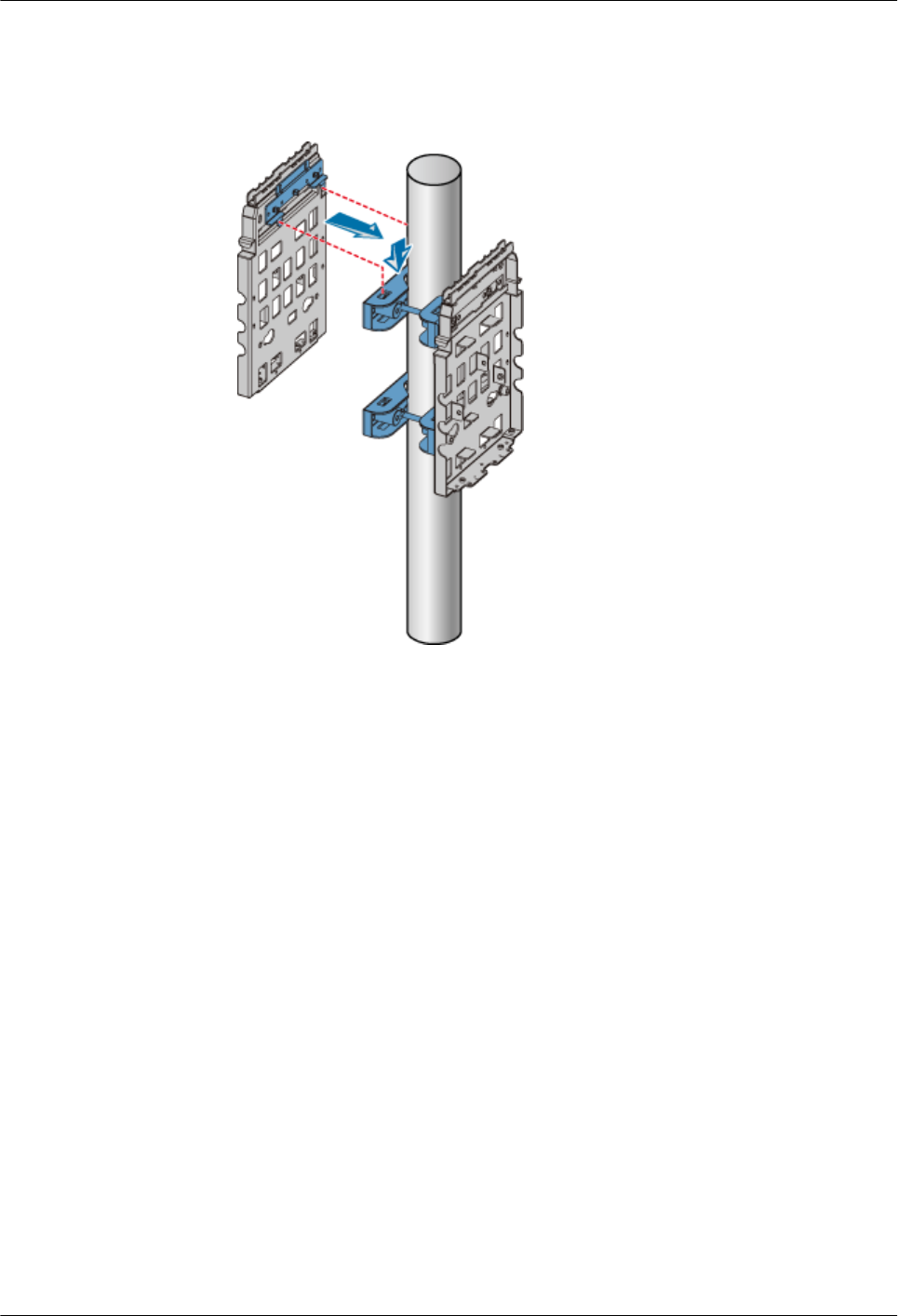
4. Hang the backplane to the fixture at the other side of the metal pole, as shown in
Figure 1-59.
Figure 1-59 Installing the second backplane
5. Get ready two M10x40 long screws, fit an M10 spring washer, M10 flat washer, and
insulation washer into each of the screws, and then use the screws to fix the second
backplane to the fixture of the metal pole, as shown in Figure 1-60.
1 RRU3606 User Guide
1-60 Huawei Proprietary and Confidential
Copyright © Huawei Technologies Co., Ltd.
Issue ()
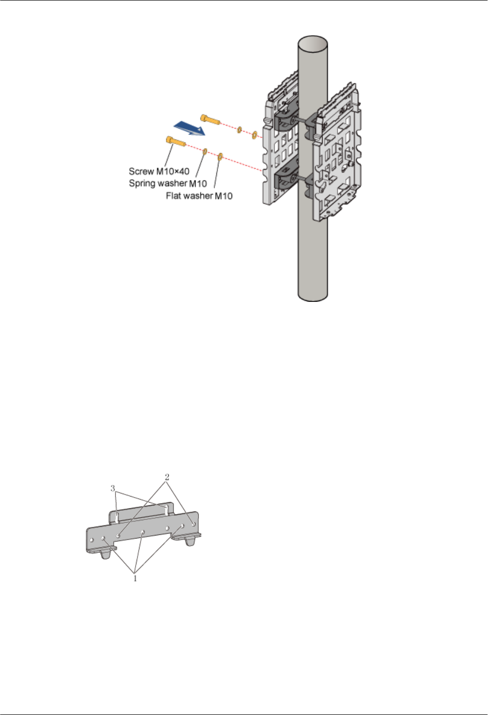
Figure 1-60 Fixing the second backplane
2. Installing the Backplanes of Two RRU3606s on the Wall
This describes how to install the backplanes of two RRU3606s on the wall.
Procedure
Step 1 Install the first backplane. For details, refer to 1.3.4.1.3 Installing the Backplane of a Single
RRU3606 on the Wall.
Step 2 Install the other backplane through installation holes marked 2 in Figure 1-61.
Figure 1-61 Choosing installation holes for the mounting bracket
Step 3 Use two M6x20 screws to fix the general mounting bracket to the backplane through the
installation holes of the mounting bracket and the corresponding installation holes at the bottom
of the backplane, as shown in Figure 1-62.
1 RRU3606 User Guide
Issue () Huawei Proprietary and Confidential
Copyright © Huawei Technologies Co., Ltd.
1-61
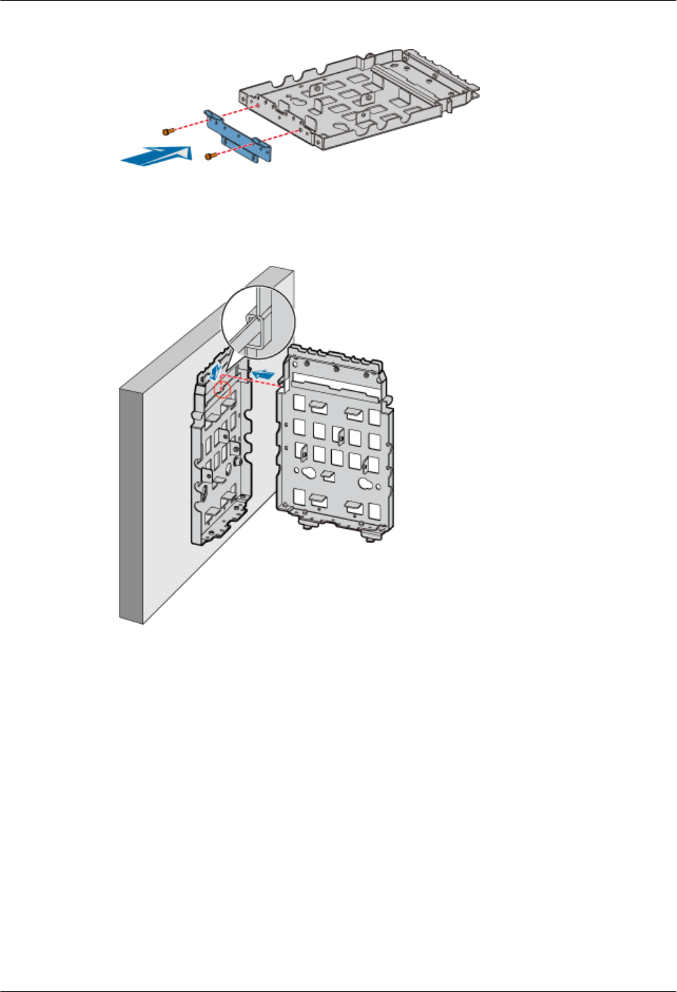
Figure 1-62 Installing the general mounting bracket at the bottom of the backplane
Step 4 Fit the assembly hook of the second backplane into the center of the double RRU assembly slot
of the first backplane, as shown in Figure 1-63.
Figure 1-63 Assembling two backplanes
Step 5 Fasten the M6x20 screws in the center and at the bottom of the backplanes, as shown in Figure
1-64.
1 RRU3606 User Guide
1-62 Huawei Proprietary and Confidential
Copyright © Huawei Technologies Co., Ltd.
Issue ()
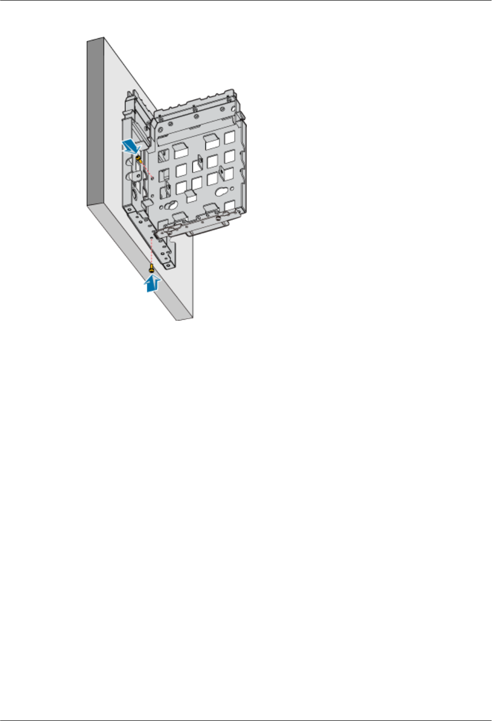
Figure 1-64 Fastening the screws on the backplanes
----End
3. Installing Two RRU3606s in Centralized Mode
This describes how to install two RRU3606s in centralized mode. In different scenarios, the
procedures for installing two RRU3606s on the backplanes are the same. This document takes
the pole installation scenario as an example.
Prerequisite
lThe backplanes of the RRU3606s are already installed.
lIf the RRU3606s are to be installed on a metal pole, the protection grounding cable of the
metal pole is already installed.
Installation Instructions
There are two modes for the installation of backplanes on a metal pole. Accordingly, there are
two modes for the installation of the RRU3606s on a metal pole. You should choose one of the
following modes based on the installation mode of the backplanes:
lSide-by-side mode
lBack-to-back mode
Installation Procedure
lSide-by-side mode
1 RRU3606 User Guide
Issue () Huawei Proprietary and Confidential
Copyright © Huawei Technologies Co., Ltd.
1-63
CAUTION
The RRU3606 on the left must be installed in rear mode, and the RRU3606 on the right
must be installed in front mode. In this way, the cabling cavities face the outside.
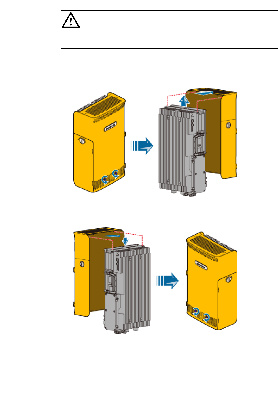
1. Remove the plastic shell of the RRU3606 that is to be installed in rear mode, as shown
in Figure 1-65.
Figure 1-65 Removing the plastic shell
2. Install the RRU3606 into the plastic shell in rear mode, as shown in Figure 1-66.
Figure 1-66 Installing the RRU3606 in rear mode
3. Use two M6x20 screws to fix the mounting bracket to the RRU3606, as shown in
Figure 1-67.
1 RRU3606 User Guide
1-64 Huawei Proprietary and Confidential
Copyright © Huawei Technologies Co., Ltd.
Issue ()
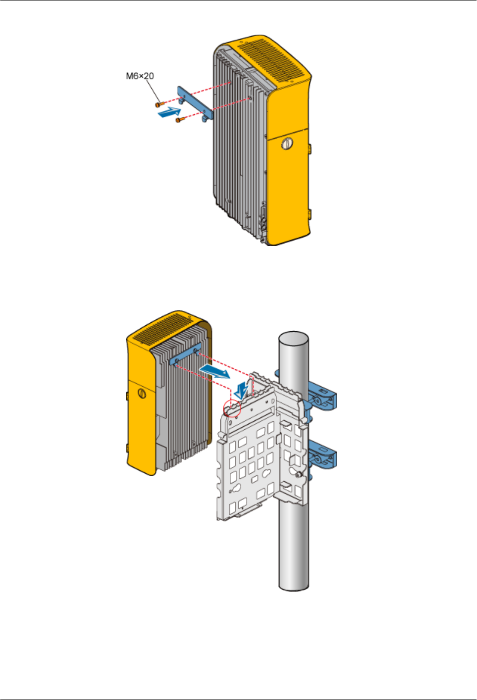
Figure 1-67 Fixing the mounting bracket to the RRU3606
4. Fit the hook of the RRU3606 to be installed in rear mode into the outermost slot on
the front of the side backplane, as shown in Figure 1-68.
Figure 1-68 Installing the first RRU3606
5. Use two M6x20 screws to fix the RRU3606 to the backplane through the installation
holes at the bottom of the backplane, as shown in Figure 1-69.
1 RRU3606 User Guide
Issue () Huawei Proprietary and Confidential
Copyright © Huawei Technologies Co., Ltd.
1-65
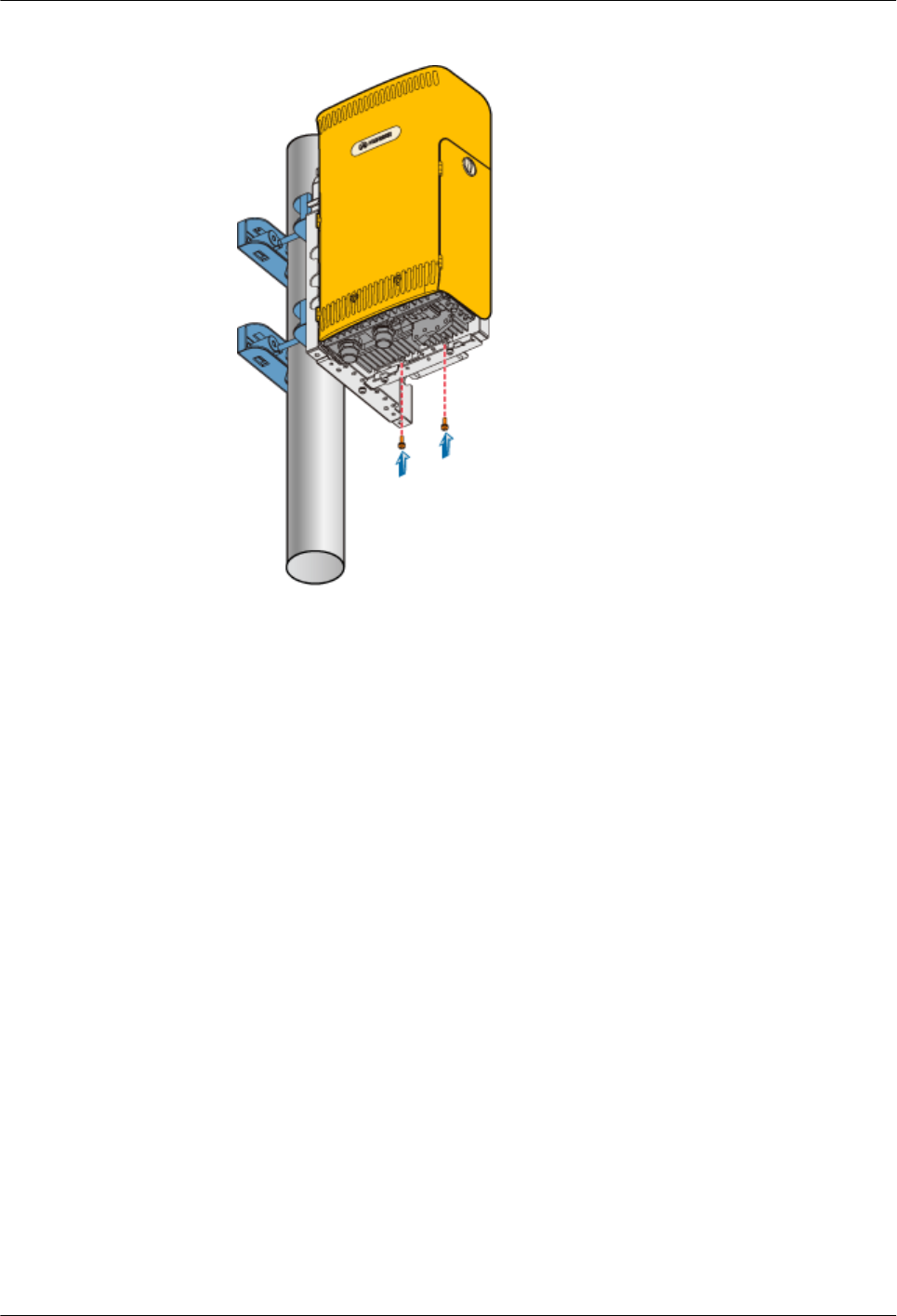
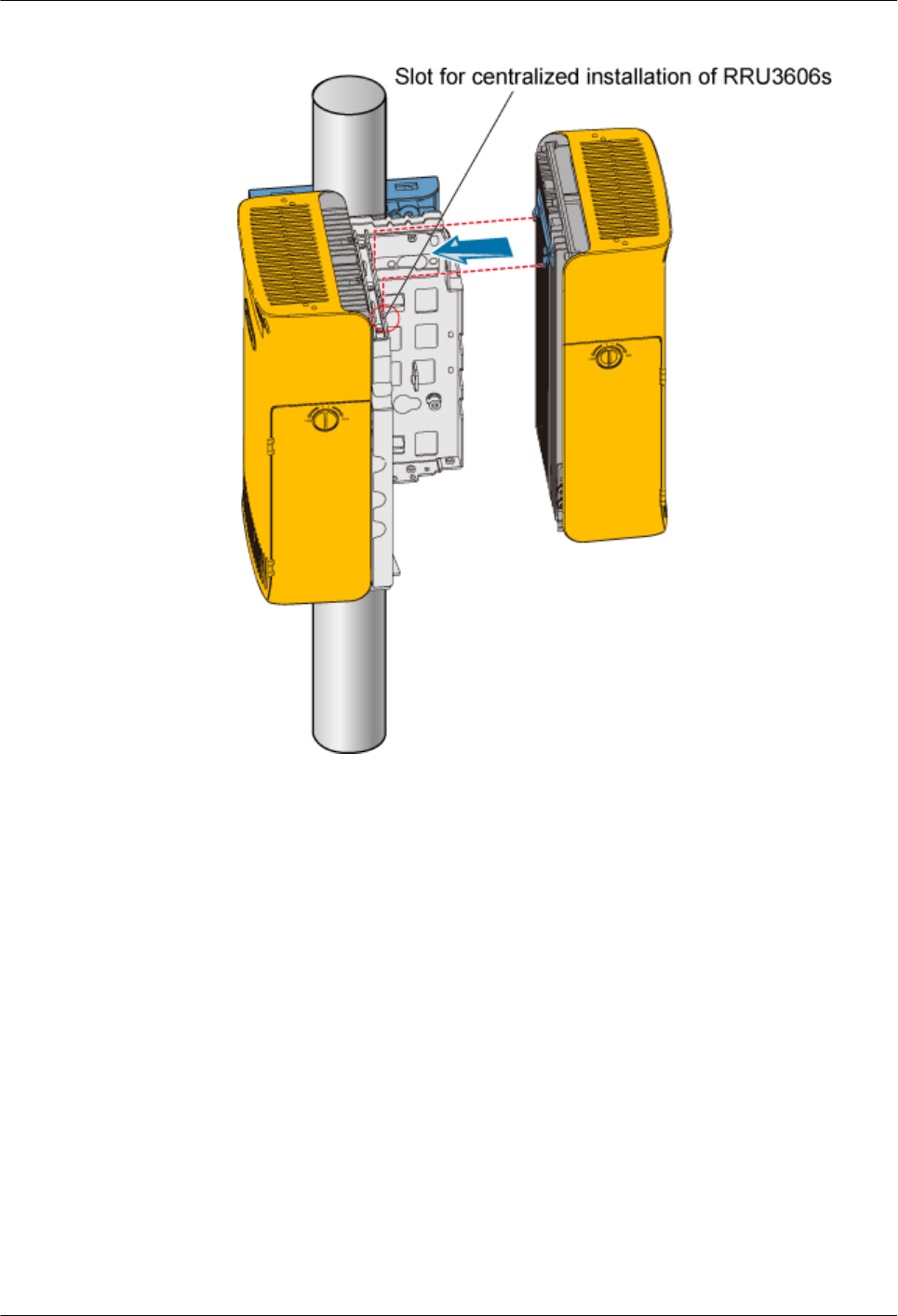
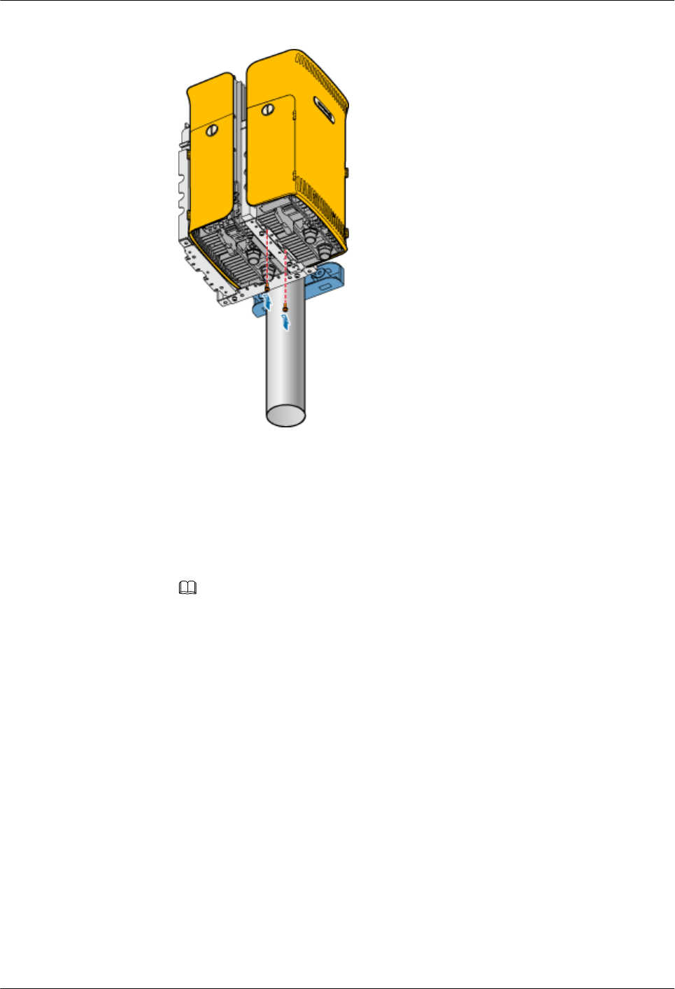
Figure 1-71 Fixing the RRU3606
lBack-to-back mode
1. Install the first RRU3606. For details, refer to 1.3.4.1.4 Installing a Single
RRU3606.
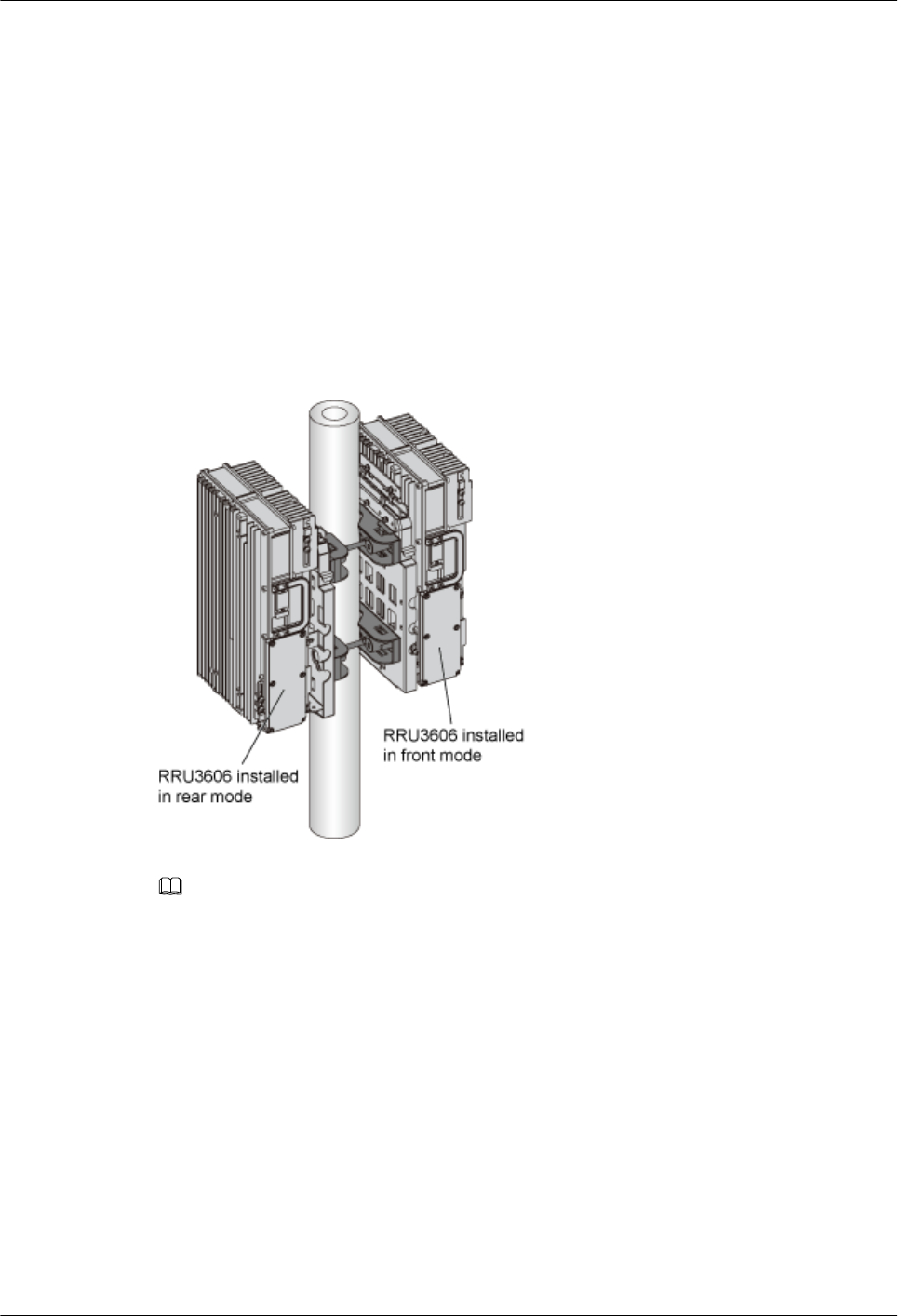
2. If the second RRU3606 is to be installed in front mode, follow the same way as you
install the first RRU3606. If the second RRU3606 is to be installed in rear mode, you
need to remove the shell first, and then install the RRU3606 in the shell in rear mode,
as shown in Figure 1-65 and Figure 1-66.
NOTE
It is recommended that the second RRU3606 be installed in rear mode so that the cabling
cavities of the two RRU3606s are on the same side, as shown in Figure 1-72.
1 RRU3606 User Guide
1-68 Huawei Proprietary and Confidential
Copyright © Huawei Technologies Co., Ltd.
Issue ()
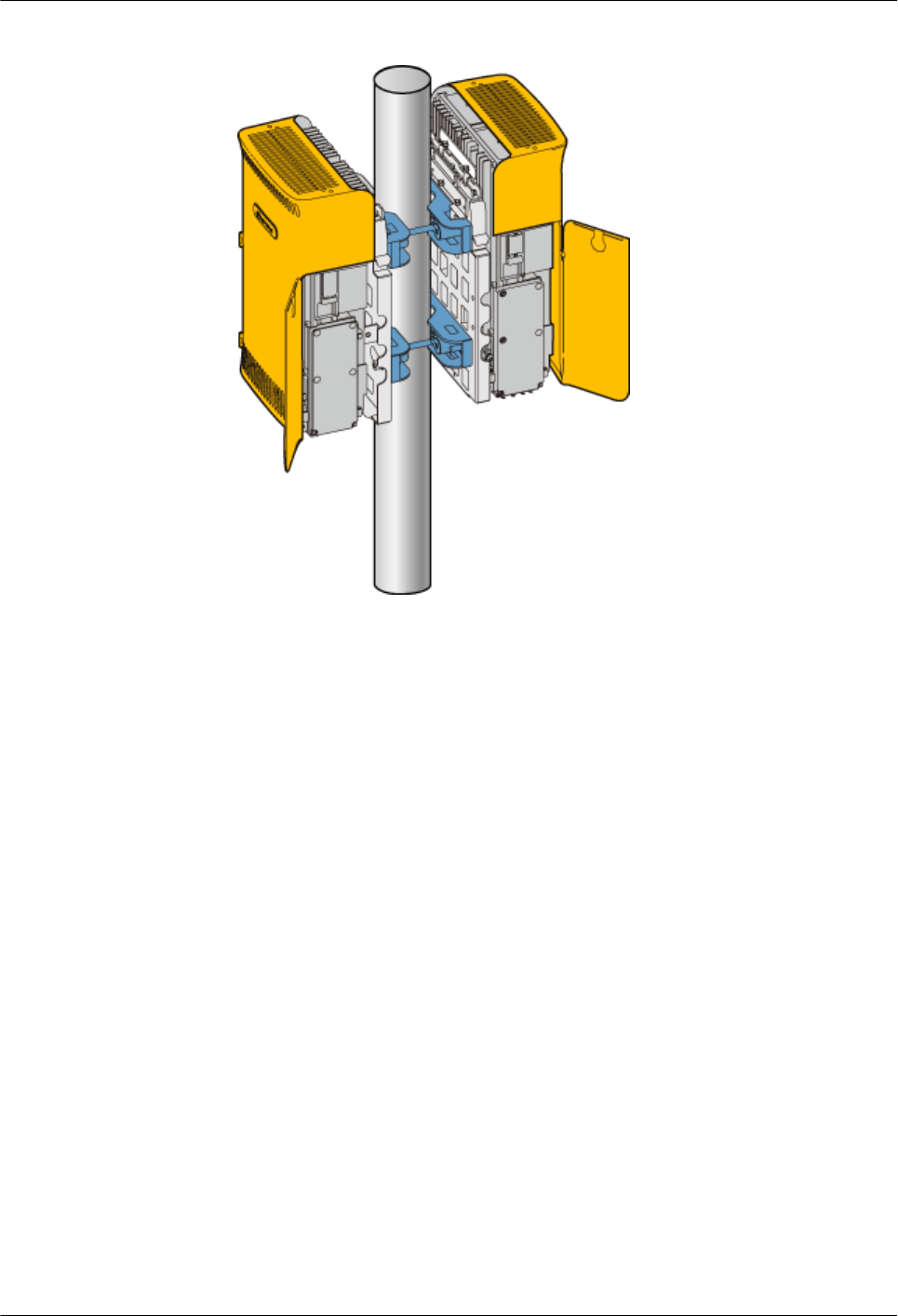
Figure 1-72 Installing the RRU3606s (cabling cavities on the same side)
Installing Three RRU3606s in Centralized Mode
This describes how to install three RRU3606s in centralized mode. You can install three
RRU3606s on a metal pole or wall.
1.3.4.3.1 Installing the Backplanes of Three RRU3606s on the Metal Pole
This describes how to install the backplanes of three RRU3606s on a metal pole.
1.3.4.3.2 Installing the Backplanes of Three RRU3606s on the Wall
This describes how to install the backplanes of three RRU3606s on the wall.
1.3.4.3.3 Install Three RRU3606s in Centralized Mode
This describes how to install a single RR3606 on a metal pole. The procedures for installing
three RRU3606s on the backplane in different scenarios are the same.
1. Installing the Backplanes of Three RRU3606s on the Metal Pole
This describes how to install the backplanes of three RRU3606s on a metal pole.
Prerequisite
A metal pole whose diameter is 60 mm [2.36 in.] to 110 mm [4.33 in.] is available.
Installation Instructions
You can install the three RRU3606s at the same side, that is, in side-by-side mode. Alternatively,
you can install two RRU3606s at one side of the pole and the other RRU3606 at the opposite
side, that is, in 2+1 mode, which facilitates carrier expansion.
Figure 1-73 shows the top view of the RRU3606s installed in side-by-side mode.
1 RRU3606 User Guide
Issue () Huawei Proprietary and Confidential
Copyright © Huawei Technologies Co., Ltd.
1-69
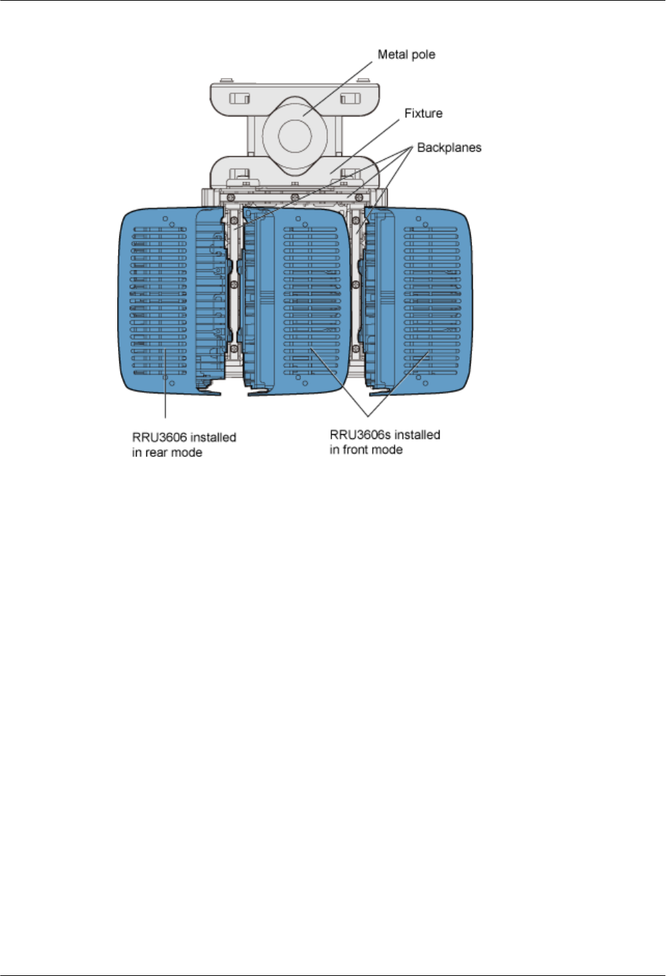
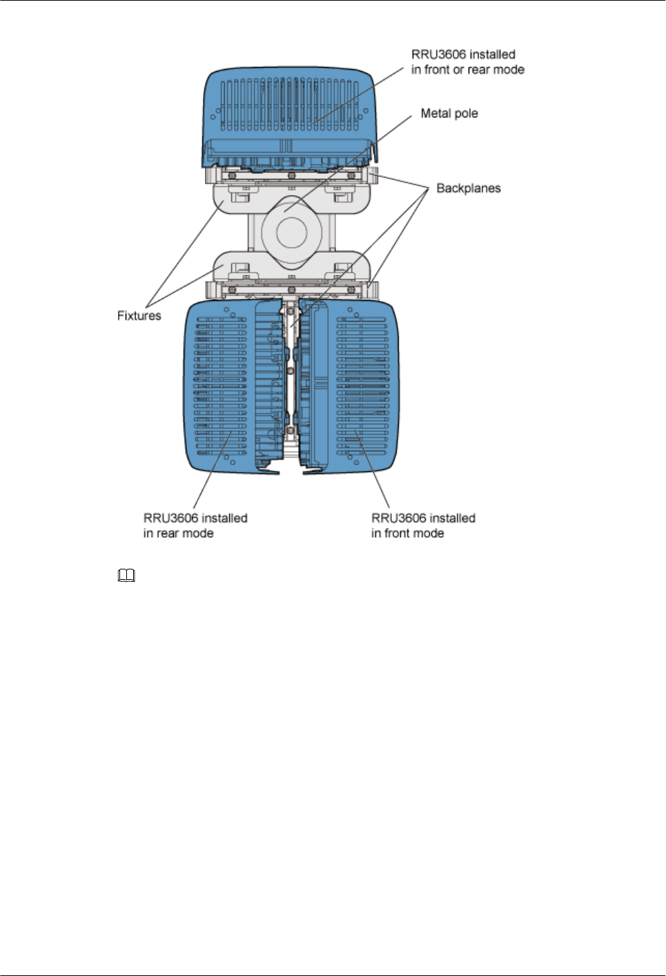
Figure 1-74 Top view of the RRU3606s installed in 2+1 mode
NOTE
lThe RRU3606s can be installed in rear or front mode. You should choose a proper mode for each
RRU3606 so that the cabling cavities face the space reserved for operation and maintenance.
lThe side-by-side mode is described here. For details on the 2+1 mode, see 1.3.4.1.1 Installing the
Backplane of a Single RRU3606 on a Metal Pole and 1.3.4.2.1 Installing the Backplanes of Two
RRU3606s on the Metal Pole.
Installation Procedure
lSide-by-side mode
1. Install the first backplane. For details, refer to 1.3.4.1.1 Installing the Backplane of
a Single RRU3606 on a Metal Pole.
2. Install the other backplane through installation holes marked 2 in Figure 1-75.
1 RRU3606 User Guide
Issue () Huawei Proprietary and Confidential
Copyright © Huawei Technologies Co., Ltd.
1-71
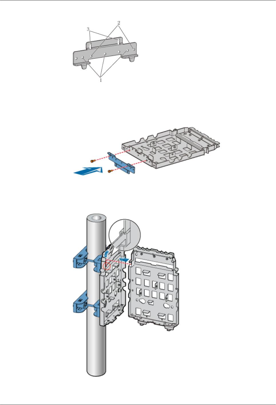
Figure 1-75 Choosing installation holes for the mounting bracket
3. Use two M6x20 screws to fix the general mounting bracket to the backplane through
the installation holes of the mounting bracket and the corresponding installation holes
at the bottom of the second backplane, as shown in Figure 1-76.
Figure 1-76 Installing the general mounting bracket at the bottom of the backplane
4. Fit the assembly hook of the second backplane into the left part of the three-RRU
assembly slot of the first backplane, as shown in Figure 1-77.
Figure 1-77 Assembling two backplanes
5. Fasten the M6x20 screws in the center and at the bottom of the backplanes, as shown
in Figure 1-78.
1 RRU3606 User Guide
1-72 Huawei Proprietary and Confidential
Copyright © Huawei Technologies Co., Ltd.
Issue ()
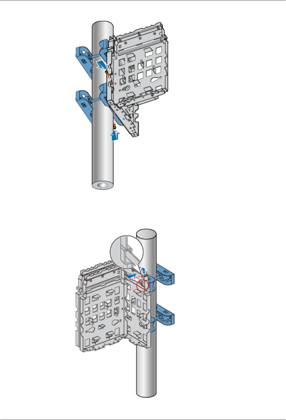
Figure 1-78 Fastening the screws on the backplanes
6. Fit the assembly hook of the third backplane into the right part of the three-RRU
assembly slot of the first backplane, as shown in Figure 1-79.
Figure 1-79 Installing the third backplane
1 RRU3606 User Guide
Issue () Huawei Proprietary and Confidential
Copyright © Huawei Technologies Co., Ltd.
1-73
7. Fasten the M6x20 screws in the center and at the bottom of the backplanes, as shown
in Figure 1-80.
Figure 1-80 Fastening the screws on the backplanes
2. Installing the Backplanes of Three RRU3606s on the Wall
This describes how to install the backplanes of three RRU3606s on the wall.
Procedure
Step 1 Install the first backplane. For details, refer to 1.3.4.1.3 Installing the Backplane of a Single
RRU3606 on the Wall.
Step 2 Install the second backplane through installation holes marked 2 in Figure 1-73.
Figure 1-81 Choosing installation holes for the mounting bracket
Step 3 Use two M6x20 screws to fix the general mounting bracket to the backplane through the
installation holes of the mounting bracket and the corresponding installation holes at the bottom
of the second backplane, as shown in Figure 1-74.
1 RRU3606 User Guide
1-74 Huawei Proprietary and Confidential
Copyright © Huawei Technologies Co., Ltd.
Issue ()
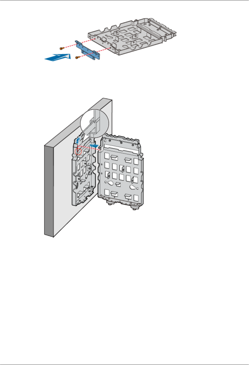
Figure 1-82 Installing the general mounting bracket at the bottom of the backplane
Step 4 Fit the assembly hook of the second backplane into the left part of the three-RRU assembly slot
of the first backplane, as shown in Figure 1-75.
Figure 1-83 Assembling two backplanes
Step 5 Fasten the M6x20 screws in the center and at the bottom of the backplanes, as shown in Figure
1-76.
1 RRU3606 User Guide
Issue () Huawei Proprietary and Confidential
Copyright © Huawei Technologies Co., Ltd.
1-75
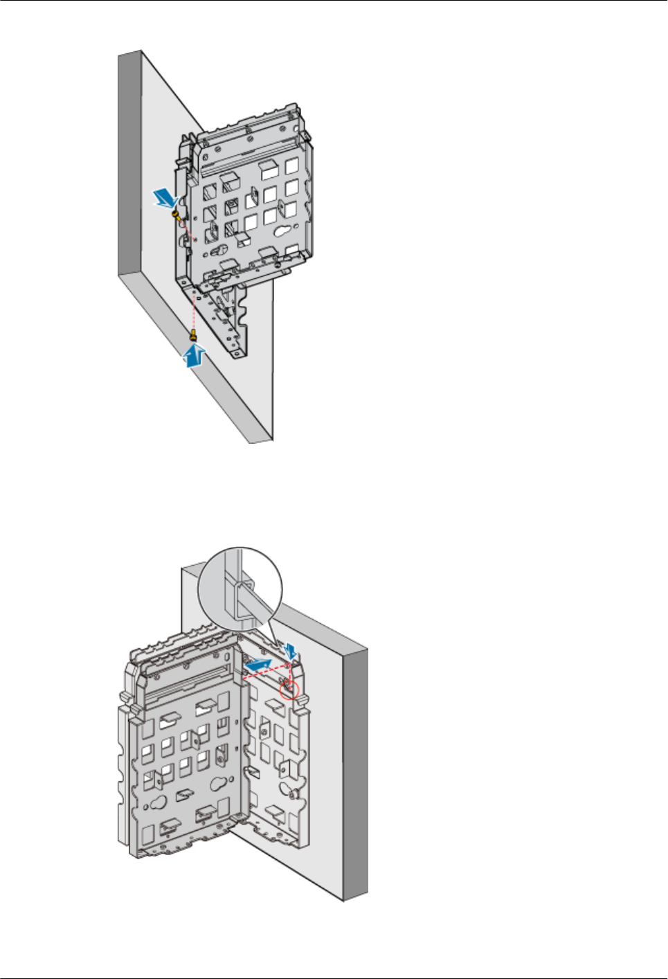
Figure 1-84 Fastening the screws on the backplanes
Step 6 Fit the assembly hook of the third backplane into the right part of the three-RRU assembly slot
of the first backplane, as shown in Figure 1-77.
Figure 1-85 Installing the third backplane
Step 7 Fasten the M6x20 screws in the center and at the bottom of the backplanes, as shown in Figure
1-78.
1 RRU3606 User Guide
1-76 Huawei Proprietary and Confidential
Copyright © Huawei Technologies Co., Ltd.
Issue ()
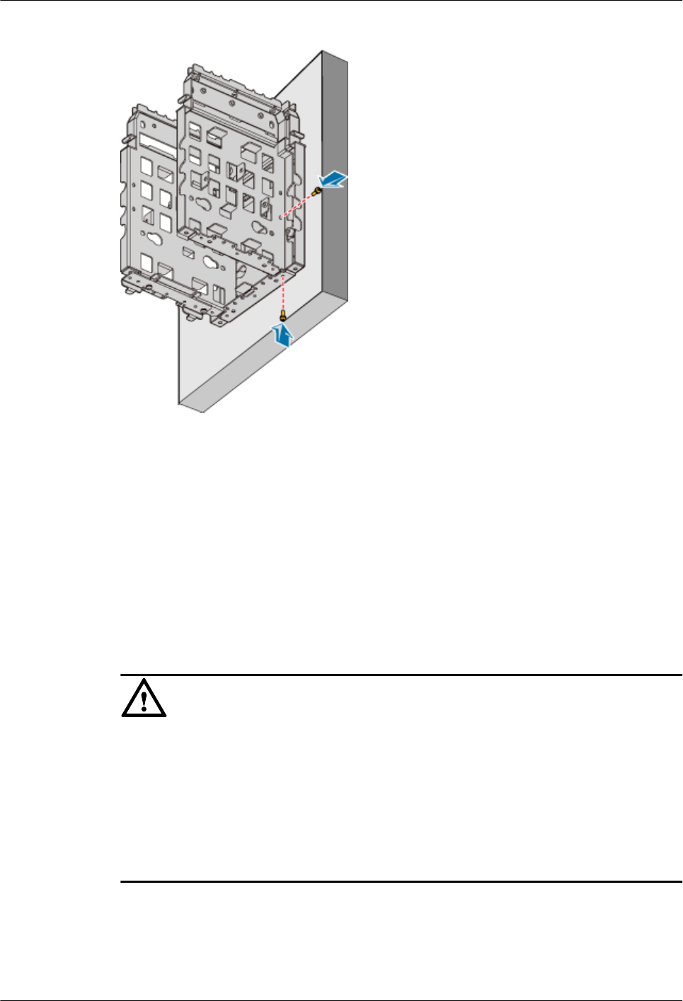
Figure 1-86 Fastening the screws on the backplanes
----End
3. Install Three RRU3606s in Centralized Mode
This describes how to install a single RR3606 on a metal pole. The procedures for installing
three RRU3606s on the backplane in different scenarios are the same.
Prerequisite
lThe backplane of the RRU3606 is already installed.
lIf the RRU3606 is to be installed on a metal pole, the grounding protection cable of the
metal pole is already correctly connected.
CAUTION
lWhen installing three RRU3606s in centralized mode, install the RRU3606 in the middle
first. Otherwise, the RRU3606 in the middle cannot be installed.
lThe RRU3606s in the middle and on the right must be installed in front mode, and the
RRU3606 on the left must be installed in rear mode. In this way, the cabling cavity faces the
outside.
lWhen installing three RRU3606s, fit the hook on the mounting bracket into the outermost
slot on the backplane.
Procedure
Step 1 Use two M6x20 screws to fix the mounting bracket to the RRU3606, as shown in Figure
1-87.
1 RRU3606 User Guide
Issue () Huawei Proprietary and Confidential
Copyright © Huawei Technologies Co., Ltd.
1-77
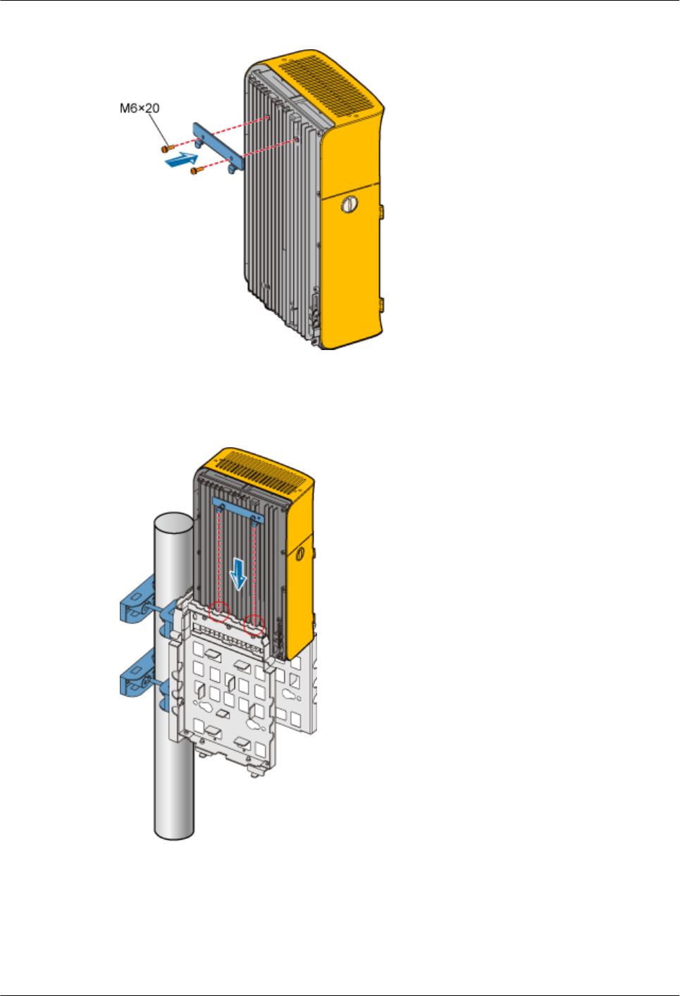
Figure 1-87 Fixing the mounting bracket
Step 2 Fit the hook of the RRU3606 into the three-RRU assembly slot at the rear of the backplane on
the left, as shown in Figure 1-88.
Figure 1-88 Installing the first RRU3606
Step 3 Use two M6x20 screws to fix the RRU3606 to the backplane through the installation holes at
the bottom of the backplane, as shown in Figure 1-89.
1 RRU3606 User Guide
1-78 Huawei Proprietary and Confidential
Copyright © Huawei Technologies Co., Ltd.
Issue ()
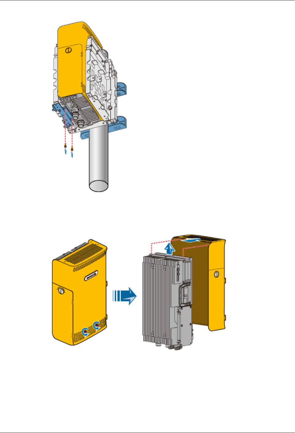
Figure 1-89 Fixing the RRU3606
Step 4 Remove the plastic shell of the RRU3606 that is to be installed in rear mode, as shown in Figure
1-90.
Figure 1-90 Removing the plastic shell
Step 5 Install the RRU3606 into the plastic shell in rear mode, as shown in Figure 1-91.
1 RRU3606 User Guide
Issue () Huawei Proprietary and Confidential
Copyright © Huawei Technologies Co., Ltd.
1-79
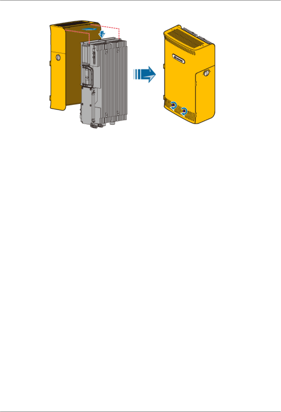
Figure 1-91 Installing the RRU3606 in rear mode
Step 6 Use two M6x20 screws to fix the mounting bracket to the RRU3606 that is installed in the rear
mode, as shown in Figure 1-87.
Step 7 Fit the hook of the RRU3606 that is installed in rear mode into the slot at the front of the backplane
on the left, as shown in Figure 1-92.
1 RRU3606 User Guide
1-80 Huawei Proprietary and Confidential
Copyright © Huawei Technologies Co., Ltd.
Issue ()
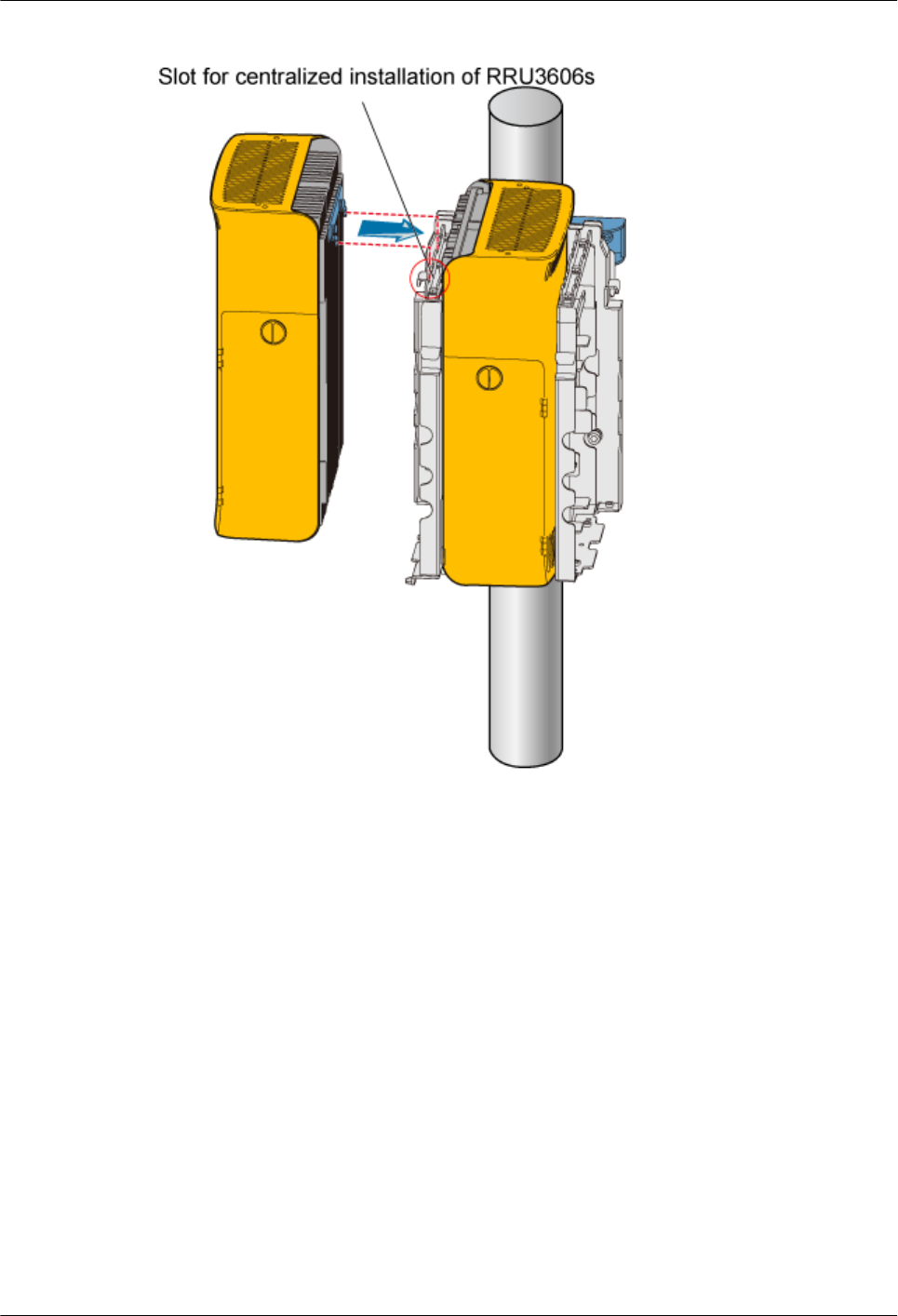
Figure 1-92 Installing the second RRU3606
Step 8 Use two M6x20 screws to fix the RRU3606 to the backplane through the installation holes at
the bottom of the backplane, as shown in Figure 1-93.
1 RRU3606 User Guide
Issue () Huawei Proprietary and Confidential
Copyright © Huawei Technologies Co., Ltd.
1-81
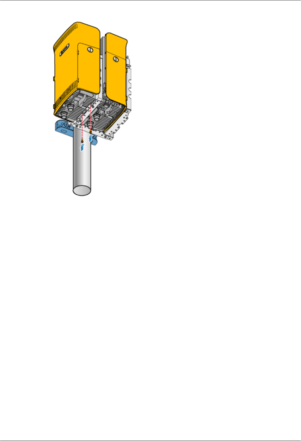
Figure 1-93 Fixing the second RRU3606
Step 9 Use two M6x20 screws to fix the mounting bracket to the third RRU3606, as shown in Figure
1-87.
Step 10 Fit the hook of the RRU3606 to be installed in front mode into the slot at the rear of the backplane
on the right, as shown in Figure 1-94.
1 RRU3606 User Guide
1-82 Huawei Proprietary and Confidential
Copyright © Huawei Technologies Co., Ltd.
Issue ()
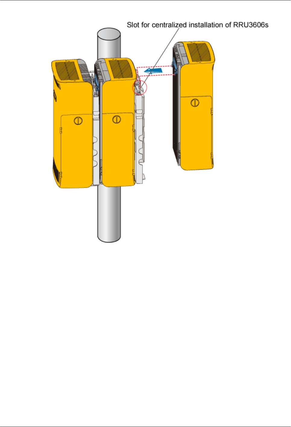
Figure 1-94 Installing the third RRU3606
Step 11 Use two M6x20 screws to fix the RRU3606 to the backplane through the installation holes at
the bottom of the backplane, as shown in Figure 1-95.
1 RRU3606 User Guide
Issue () Huawei Proprietary and Confidential
Copyright © Huawei Technologies Co., Ltd.
1-83
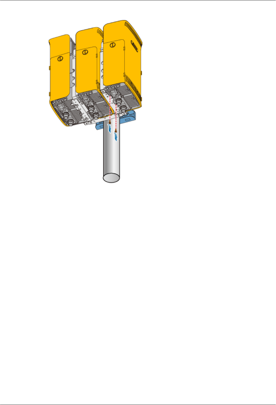
Figure 1-95 Fixing the third RRU3606
----End
1.3.5 Installing and Removing the Cables of the RRU3606
This describes how to install and remove the cables of the RRU3606 and how to install the cover
of the cabling cavity of the RRU3606.
1.3.5.1 Opening the Cover of the Cabling Cavity of the RRU3606
This describes how to open the cover of the cabling cavity.
1.3.5.2 Installing the Protection Grounding Cable of the RRU3606
This describes how to install the protection grounding cable of the RRU3606.
1.3.5.3 Installing the Power Cable of the RRU3606
This describes how to install the power cable of the RRU3606.
1.3.5.4 Installing the RF Jumper of the RRU3606
This describes how to install the RF jumper of the RRU3606.
1.3.5.5 Installing the Optical Fiber of the RRU3606
This describes how to install optical fibers for the RRU3606.
1.3.5.6 Installing the Alarm Cable of the RRU3606
This describes how to install the alarm cable of the RRU3606.
1.3.5.7 Installing the Cover of the Cabling Cavity
This describes how to install the cover of the cabling cavity.
Opening the Cover of the Cabling Cavity of the RRU3606
This describes how to open the cover of the cabling cavity.
1 RRU3606 User Guide
1-84 Huawei Proprietary and Confidential
Copyright © Huawei Technologies Co., Ltd.
Issue ()
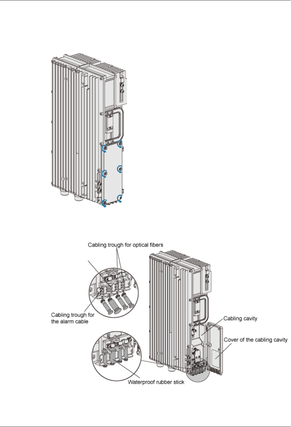
Procedure
Step 1 Loosen the six captive screws on the cover of the cabling cavity, as shown in Figure 1-96.
Figure 1-96 Loosening the captive screws on the cover of the cabling cavity
Step 2 Open the cover of the cabling cavity, as shown in Figure 1-97.
Figure 1-97 Opening the cover of the cabling cavity
1 RRU3606 User Guide
Issue () Huawei Proprietary and Confidential
Copyright © Huawei Technologies Co., Ltd.
1-85
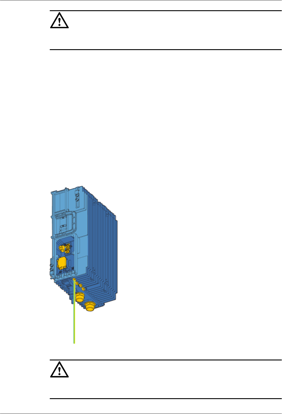
CAUTION
Waterproof rubber sticks are preinstalled in the wiring trough. Keep unused waterproof rubber
sticks for future use.
----End
Installing the Protection Grounding Cable of the RRU3606
This describes how to install the protection grounding cable of the RRU3606.
Procedure
Step 1 Route the protection grounding cable. For details, see 1.3.1.3 Requirements for Routing
Cables of the RRU3606.
Step 2 Prepare OT terminals for the protection grounding cable.
Step 3 Install the protection grounding cable of the RRU3606, as shown in Figure 1-98.
Figure 1-98 Installing the protection grounding cable
CAUTION
When installing the OT terminals, ensure that the crimping socket faces the correct direction, as
shown in Figure 1-99.
1 RRU3606 User Guide
1-86 Huawei Proprietary and Confidential
Copyright © Huawei Technologies Co., Ltd.
Issue ()
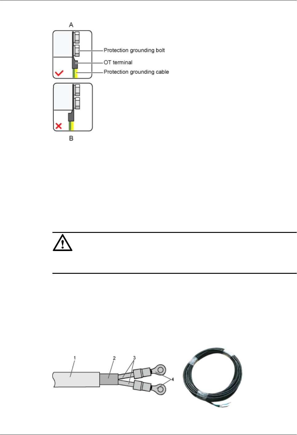
Figure 1-99 Direction of the crimping socket
Step 4 Connect the other end of the protection grounding cable to the closest grounding bar.
----End
Installing the Power Cable of the RRU3606
This describes how to install the power cable of the RRU3606.
Prerequisite
CAUTION
If a DC power cable is used to supply external power to the RRU3606, the power cable must be
a shielded power cable. Otherwise, the equipment is prone to lightning strikes.
Procedure
Step 1 Route the power cable. For details, see 1.3.1.3 Requirements for Routing Cables of the
RRU3606.
Step 2 Prepare the input terminal of the power cable, as shown in Figure 1-100.
Figure 1-100 Input terminal of the power cable
(1) -48 V DC power cable (2) Shielding layer (3) Wire (4) OT terminal
1 RRU3606 User Guide
Issue () Huawei Proprietary and Confidential
Copyright © Huawei Technologies Co., Ltd.
1-87
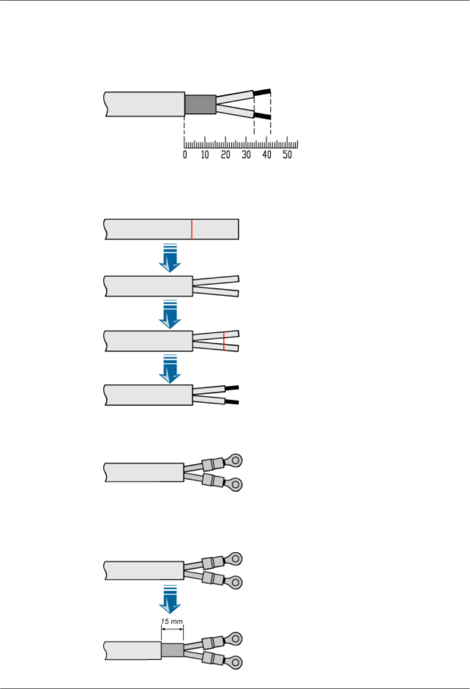
The procedure for preparing the input terminal is as follows:
1. Determine the lengths of each cable section according to the labels on the inside of the
cabling cavity. Figure 1-101 shows the labels.
Figure 1-101 Labels for preparing the power cable
2. Based on the labels, peel part of the outer jacket and shielding layer, and then peel part of
the jacket according to the labels, as shown in Figure 1-102.
Figure 1-102 Peeling the cable
3. Prepare OT terminals at the two wires, as shown in Figure 1-103.
Figure 1-103 OT terminals of the power cable
4. Based on the labels, peel about 15 mm [0.59 in.] of the outer jacket to expose the shielding
layer, as shown in Figure 1-104.
Figure 1-104 Peeling the outer jacket
1 RRU3606 User Guide
1-88 Huawei Proprietary and Confidential
Copyright © Huawei Technologies Co., Ltd.
Issue ()
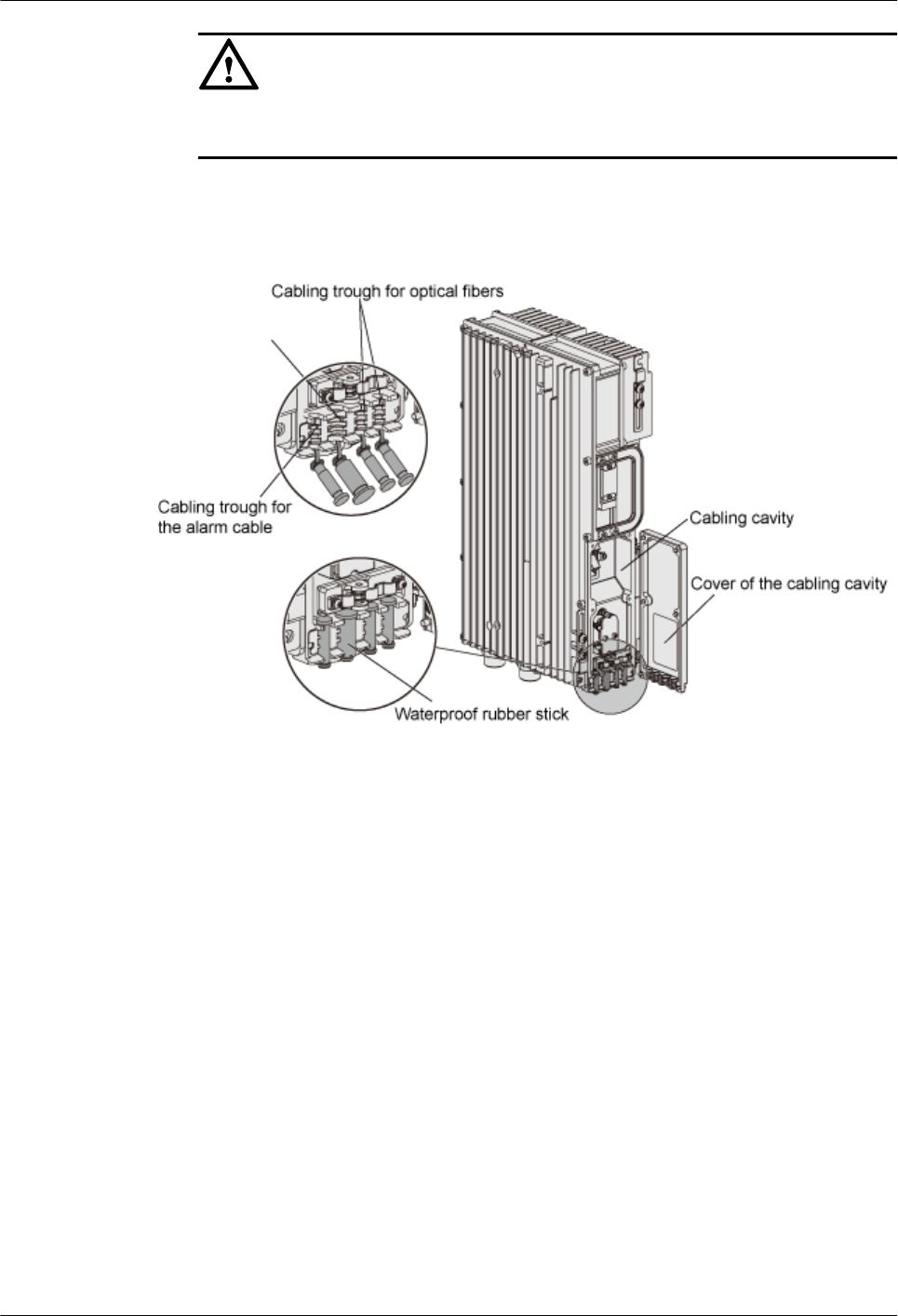
CAUTION
This step can be performed only after the previous steps are complete. Otherwise, the
exposed part of the shielding layer becomes messy.
Step 3 Take out the waterproof sticks in the cabling trough in the cabling cavity, and then route the
power cable along the cabling trough. Figure 1-105 shows the position of the cabling trough.
Figure 1-105 Position of the cabling trough
Step 4 Open the cover above the power cable input terminal, as shown in Figure 1-106.
1 RRU3606 User Guide
Issue () Huawei Proprietary and Confidential
Copyright © Huawei Technologies Co., Ltd.
1-89
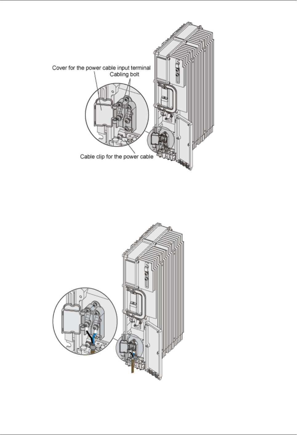
Figure 1-106 Opening the cover above the power cable input terminal
Step 5 Connect the OT terminal of the -48 V wire (blue) to the terminal marked NEG (-) in the cabling
cavity, connect the OT terminal of the GND wire (black or brown) to the terminal marked RTN
(+) in the cabling cavity, and then fasten the screw, as shown in Figure 1-107.
Figure 1-107 Installing the power cable
Step 6 Remove the screw at the cable clip (marked PGND) of the power cable. Figure 1-106 shows
the position of the cable clip.
Step 7 Use the cable clip to fix the exposed part of the shielding layer at the input terminal of the power
cable, and then fasten the screw, as shown in Figure 1-108.
1 RRU3606 User Guide
1-90 Huawei Proprietary and Confidential
Copyright © Huawei Technologies Co., Ltd.
Issue ()
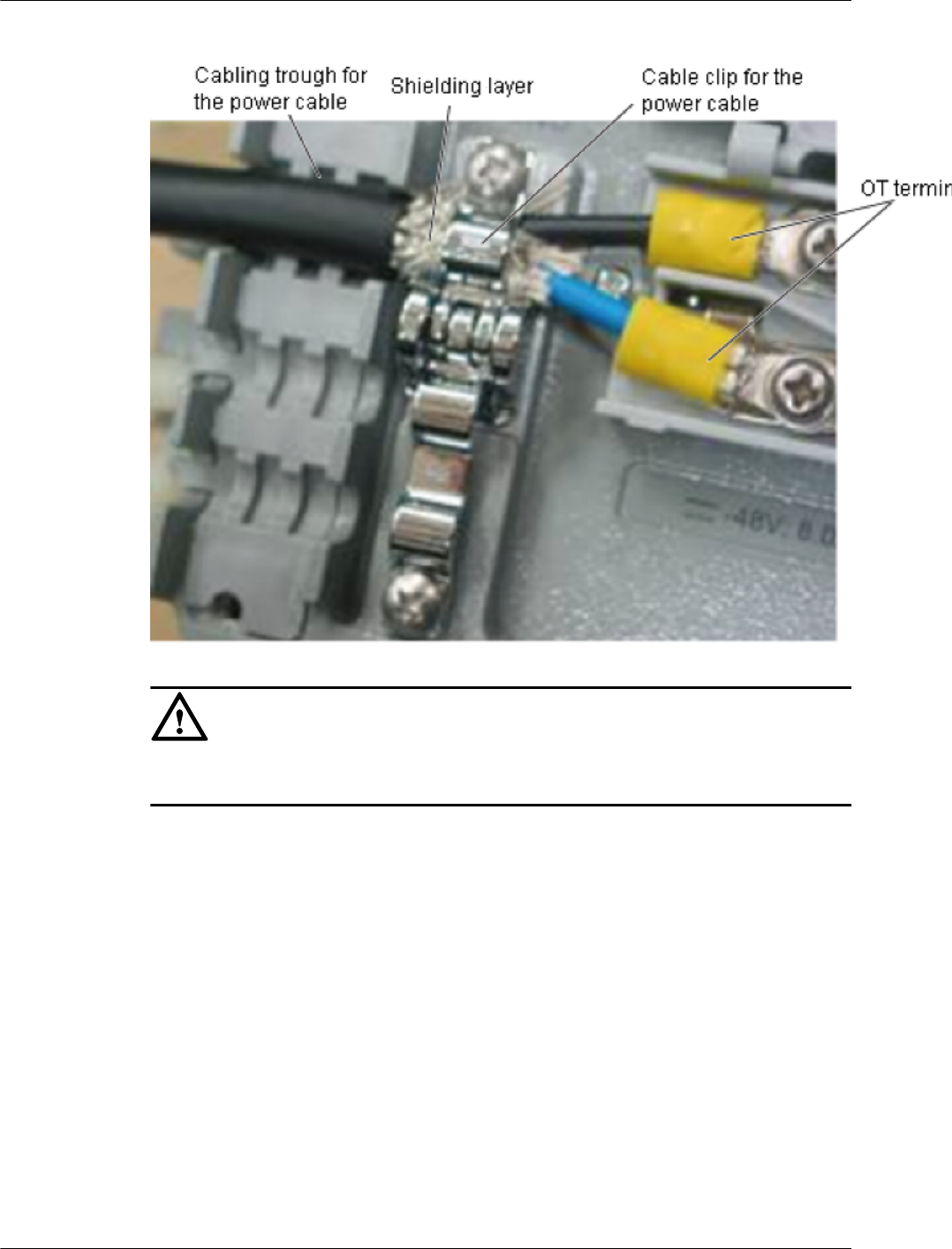
Figure 1-108 Fixing the exposed part of the shielding layer
CAUTION
Ensure that the cable clip is pressed against the shielding layer instead of the outer jacket or the
wires.
Step 8 Close the cover above the power cable input terminal.
Step 9 Bundle the power cable.
Step 10 Do as follows to connect the other end of the power cable:
1. Peel about 50 mm [1.97 in.] of the outer jacket.
2. Peel part of the shielding layer and twist this part. Then, insert the twisted part of the
shielding layer into a heat shrink tube (φ5), as shown in Figure 1-109.
1 RRU3606 User Guide
Issue () Huawei Proprietary and Confidential
Copyright © Huawei Technologies Co., Ltd.
1-91
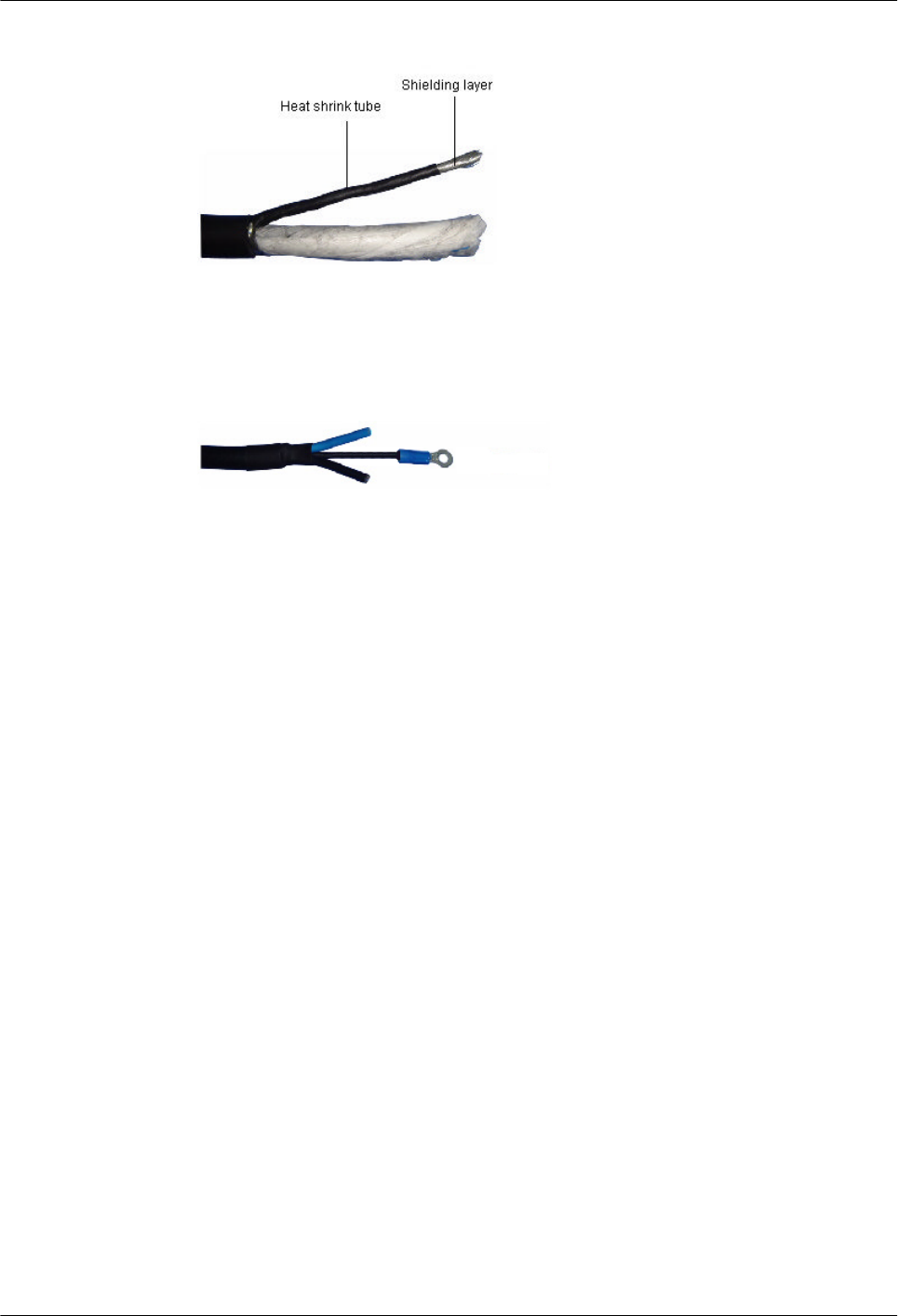
Figure 1-109 Peeling the shielding layer
3. Prepare OT terminals at the other end of the shielding layer.
4. At the peeling point of the shielding layer, use a heat shrink tube (φ14) to implement heat
shrink processing, as shown in Figure 1-110.
Figure 1-110 Heat shrink processing
5. Connect the OT terminals at the shielding layer to the corresponding grounding bar of the
power supply equipment.
6. Prepare OT terminals for the -48 V wire (blue) and GND wire (black or brown), and then
connect the terminals to corresponding wiring terminals of the power supply equipment.
----End
Installing the RF Jumper of the RRU3606
This describes how to install the RF jumper of the RRU3606.
Procedure
Step 1 Based on the distance between the bottom of the RRU3606 and the RF feeder, prepare a RF
jumper of proper length with a proper margin.
Step 2 Prepare a DIN-type connector for the RF jumper.
Step 3 Connect the RF jumper to the RF ANT_TX/RXA and ANT_RXB ports of the RRU3606, as
shown in Figure 1-111.
1 RRU3606 User Guide
1-92 Huawei Proprietary and Confidential
Copyright © Huawei Technologies Co., Ltd.
Issue ()
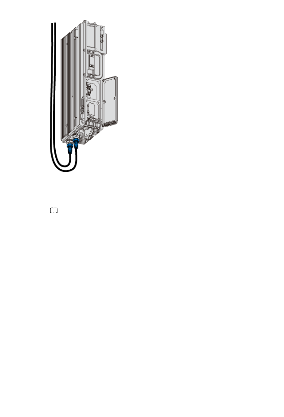
Figure 1-111 Installing the RF jumper
Step 4 Connect the other end of the RF jumper to the feeder.
Step 5 Use waterproofing and insulating tape to waterproof and seal the connection points at both ends
of the RF jumper.
NOTE
lWrap each connection point with three layers of tape, and ensure that each layer covers at least 50%
of the previous layer.
lEnsure that each layer of tape is evenly and tightly stretched. In this way, the tape does not get loose.
----End
Installing the Optical Fiber of the RRU3606
This describes how to install optical fibers for the RRU3606.
Prerequisite
Context
Procedure
Step 1 Insert the optical module into the CPRI_W port in the cabling cavity of the RRU3606.
Step 2 Insert the connector at one end of the optical fiber into the optical module.
Step 3 Remove the screws on the cable clip of the optical fiber and the waterproof rubber sticks in the
cabling trough of the optical fiber.
Step 4 Route the optical fiber along the cabling trough in the cabling cavity, use the cable clip to fix
the optical fiber, and then fasten the screw on the cable clip. Figure 1-112 shows how to install
the optical fiber.
1 RRU3606 User Guide
Issue () Huawei Proprietary and Confidential
Copyright © Huawei Technologies Co., Ltd.
1-93
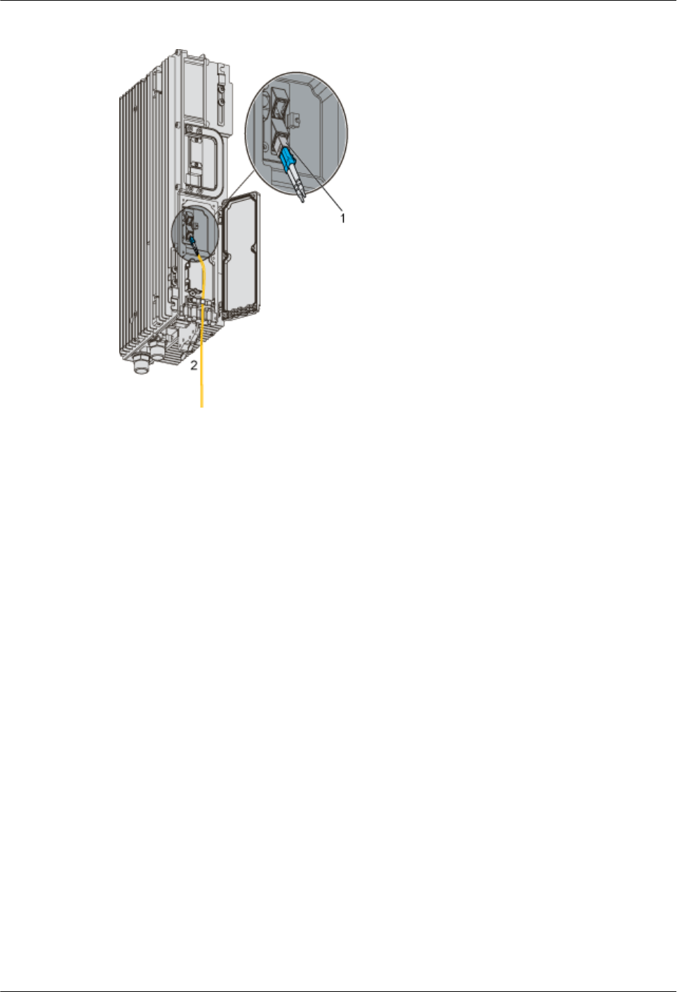
Figure 1-112 Installing the optical fiber
(1) Pluggable optical modules (2) To the BBU3900
Step 5 Route the optical fiber to the BBU3900.
Step 6 Connect the other end of the optical fiber to the optical fiber port of the BBU3900.
----End
Installing the Alarm Cable of the RRU3606
This describes how to install the alarm cable of the RRU3606.
Procedure
Step 1 Lead the alarm cable through the protection tube, and determine the length of the part of the
cable outside the protection tube according to the actual situation.
Step 2 Connect the DB15 connector of the alarm cable to the RS485/EXT_ALM port in the cabling
cavity of the RRU3606. Figure 1-113 shows how to install the alarm cable.
1 RRU3606 User Guide
1-94 Huawei Proprietary and Confidential
Copyright © Huawei Technologies Co., Ltd.
Issue ()
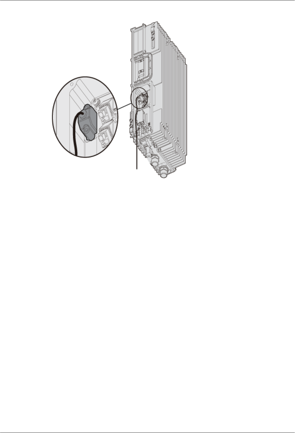
Figure 1-113 Installing the alarm cable
Step 3 Remove the waterproof rubber sticks in the wiring trough of the cabling cavity, and then route
the alarm cable along the wiring trough of the cabling cavity.
Step 4 Connect the other end of the alarm cable to the Boolean value signal port of the corresponding
auxiliary device.
Step 5 Take waterproofing and sealing measures for the holding tube.
----End
Installing the Cover of the Cabling Cavity
This describes how to install the cover of the cabling cavity.
Procedure
Step 1 Close the cover of the cabling cavity.
Step 2 Fasten the screws one by one in the sequence shown in Figure 1-114.
1 RRU3606 User Guide
Issue () Huawei Proprietary and Confidential
Copyright © Huawei Technologies Co., Ltd.
1-95
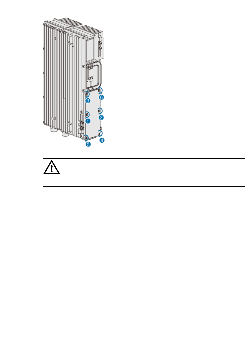
Figure 1-114 Installing the cover of the cabling cavity
CAUTION
The screws of cover must be tightly fastened. The torque requirement is 1.4 N•m.
----End
1.3.6 Powering On the RRU3606
This describes how to power on the RRU3606.
Prerequisites
Before powering on the RRU3606, ensure that:
lThe fixing pieces are securely installed, and the backplanes are properly fixed without
distortion.
lThe power cable, grounding cable, optical fiber, alarm cable, and RF feeder are intact.
lThe power cable is not short-circuited or inversely connected, and the grounding cable is
not short-circuited.
lThe optical fiber, alarm cable, and RF jumper are correctly connected and fixed.
lIf the -48 V DC power supply is used, the external input voltage should be -37 V DC to
-60 V DC.
Procedure
Step 1 Switch on the external power supply equipment of the RRU3606.
Step 2 Check the status of the indicators in the cabling cavity. Table 1-10 lists the meanings of the
indicators.
1 RRU3606 User Guide
1-96 Huawei Proprietary and Confidential
Copyright © Huawei Technologies Co., Ltd.
Issue ()
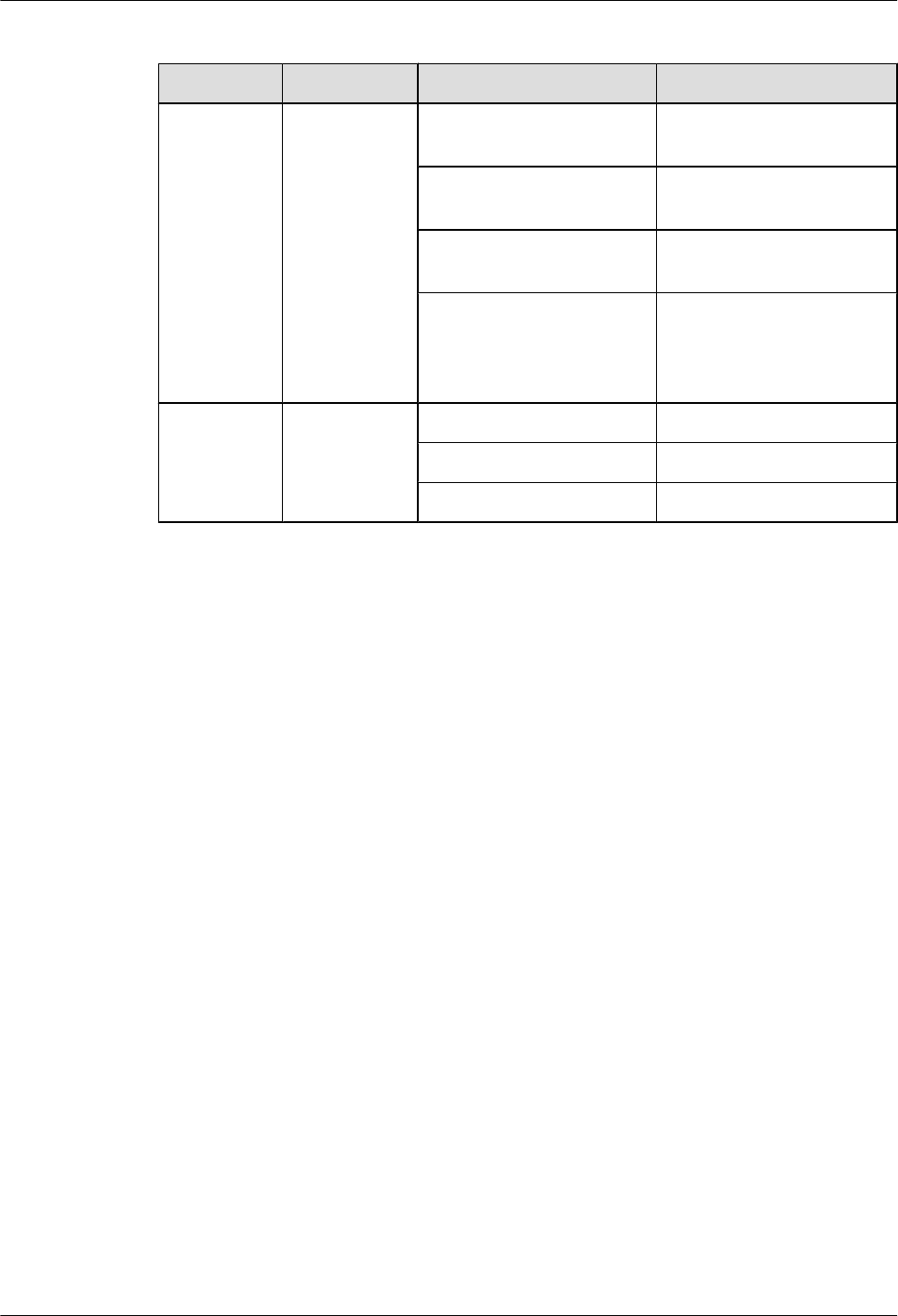
Table 1-10 Meanings of the indicators
Indicator Color Status Meaning
RUN Green ON There is power input, but the
RRU3606 is faulty.
OFF There is no power input, or
the RRU3606 is faulty.
ON for 1 second and OFF
for 1 second
The RRU3606 is working
properly.
ON for 0.5 second and OFF
for 0.5 second
The RRU3606 software is
being loaded, or the data of
the RRU3606 is not
configured.
ALM Red ON Fatal alarm
Blinking at 0.5 Hz Minor alarm
OFF No alarm
----End
1.3.7 Installing the Shell of the RRU3606
This describes how to install the shell of the RRU3606.
Background Information
During software installation and system commissioning, if you need to view the status of the
indicators through the cabling cavity, the shell can be installed after system commissioning.
Procedure
Step 1 Attach the shell to the RRU3606 by fitting the hooks of the shell into the slots at the top of the
RRU3606, as shown in Figure 1-115.
1 RRU3606 User Guide
Issue () Huawei Proprietary and Confidential
Copyright © Huawei Technologies Co., Ltd.
1-97
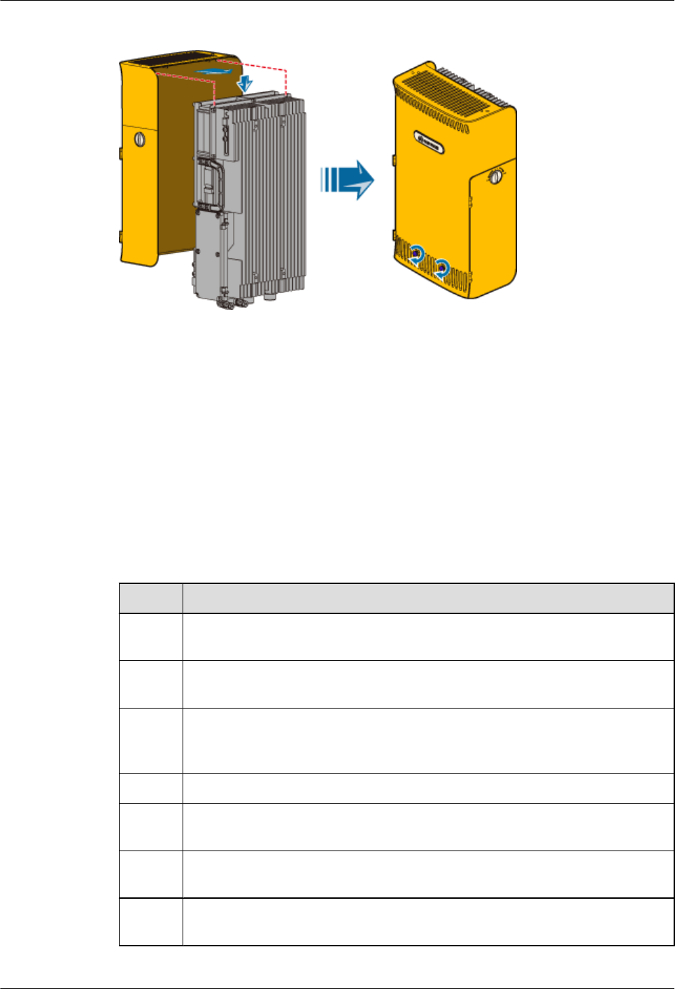
Figure 1-115 Installing the shell
Step 2 Use two M6×14 screws to fix the shell, as shown in Figure 1-115.
----End
1.3.8 Checklist for the Installation of the RRU3606
This describes the items to be checked after the RRU3606 is installed.
Checking the Installation of the Equipment
Before powering on the RRU3606, perform the checks listed in Table 1-11.
Table 1-11 Checklist for the installation of the equipment
SN Item
1The installation position of the equipment is strictly consistent with the design
drawings and meets the requirements for installation space and reserved space.
2 If the RRU3606 is installed on a metal pole or wire pole, the fixing pieces are
securely installed, and the backplanes are properly fixed without distortion.
3 If the RRU3606 is installed on a wall, the installation holes in the backplane are
aligned with the holes in the expansion bolts, and the backplane is in good contact
with the wall and securely installed.
4 The cover of the cabling cavity is tightly closed.
5 The unused wiring troughs in the cabling cavity are filled with waterproof rubber
sticks.
6 The waterproof covers and chains for the ports at the bottom of the RRU3606 are
tightly bound with nearby cables.
7 There is no scratch on the surface of the RRU3606. Otherwise, you must paint the
scratched part.
1 RRU3606 User Guide
1-98 Huawei Proprietary and Confidential
Copyright © Huawei Technologies Co., Ltd.
Issue ()
SN Item
8The surface of the RRU3606 is clean and tidy, and the labels are complete, correct,
and clear.
9 There are no engineering objects left at the site, for example, tape, binding straps,
and package bags.
Checking the Installation of the Cables
lFor the power cable and protection grounding cable, perform the checks listed in Table
1-12.
Table 1-12 Checklist for the installation of the power cable and protection grounding cable
SN Item
1The power cable and protection grounding cable are not short-circuited or
inversely connected.
2 The power cable and protection grounding cable are bound separately from
the other cables.
3 Labels are attached to both ends of the power cable and protection grounding
cable.
4 The power cable and protection grounding cable are intact.
5 The power cables and protection grounding cables have no weld nugget.
6 No disconnectable devices, such as switches and fuses, are set in the electrical
circuit of the grounding system.
7 The redundant parts of the power cable and protection grounding cable are cut
off.
8 The copper lugs at both ends of the power cable and protection grounding
cable are welded or crimped firmly.
9 The exposed wires at the connection terminals and lug handles are insulated
by insulation tape or heat shrink tubes.
10 Plain washers and spring washers are installed at all connection terminals. The
connection terminals are securely installed and in good contact.
11 The work grounding cable and protection grounding cable of the BTS share
a group of grounding conductors with the lightning and grounding cables of
the building.
lFor the signal cables, perform the checks listed in Table 1-13.
1 RRU3606 User Guide
Issue () Huawei Proprietary and Confidential
Copyright © Huawei Technologies Co., Ltd.
1-99
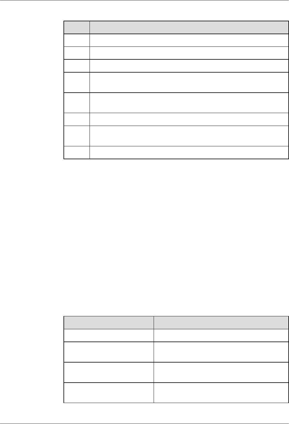
Table 1-13 Checklist for the installation of the signal cables
SN Item
1The connectors of the signal cables are securely connected.
2 The connectors of the signal cables are intact.
3 The signal cables are intact.
4 The signal cables are bound orderly and tightly. The cable ties are evenly
spaced and fastened with proper force.
5 The redundant parts of the cable ties are removed, and all cuts of the cable ties
are smooth without sharp ends.
6 A margin of 3 mm [0.12 in.] to 5 mm [0.20 in.] is reserved.
7 The placement of the signal cables is convenient for maintenance and capacity
expansion.
8 Correct and clear labels are attached to both ends of the signal cables.
Power-On Check
Before powering on the RRU3606, you need to check the voltage input to the RRU3606 and the
running status of the RRU3606.
The procedure for the power-on check is as follows:
1. Switch off the primary power supply to the RRU3606.
2. Measure the voltage input to the RRU3606. If the voltage is -37 V DC to -60 V DC, the
primary power supply is functional.
3. Switch on the power supply equipment of the RRU3606.
4. Check whether the status of the RUN indicator in the cabling cavity of the RRU3606 is
normal.
Table 1-14 lists the states of the RUN indicator.
Table 1-14 States of the RUN indicator
State Description
ON There is power input, but the board is faulty.
OFF There is no power input, or the RRU3606 is working
in alarm mode.
ON for 1 second and OFF for 1
second
The board is working properly.
ON for 0.5 second and OFF for
0.5 second
The board software is being loaded.
1 RRU3606 User Guide
1-100 Huawei Proprietary and Confidential
Copyright © Huawei Technologies Co., Ltd.
Issue ()

1.4 Maintaining the RRU3606
This describes how to maintain the RRU3606.
1.4.1 Routine Maintenance Items of the RRU3606
This describes the routine maintenance items of the RRU3606. During the routine maintenance
of the RRU3606, you need to check the surface, cleanness, and indicators of the equipment.
1.4.2 Powering On and Powering Off the RRU3606
This describes how to power on and power off the RRU3606.
1.4.3 Replacing the RRU3606
This describes how to replace a faulty RRU3606.
1.4.4 Replacing the Cables of the RRU3606
This describes how to replace the cables of the RRU3606. The power cable, RF cable, optical
fiber, and alarm cable of the RRU3606 can be replaced on site.
1.4.1 Routine Maintenance Items of the RRU3606
This describes the routine maintenance items of the RRU3606. During the routine maintenance
of the RRU3606, you need to check the surface, cleanness, and indicators of the equipment.
After the equipment is installed and starts to work properly, you should perform routine
maintenance for the equipment on a regular basis, for example, every month or season. Do as
follows to perform routine maintenance:
lCheck whether the surface of the equipment is intact and whether the labels and marks are
clear.
lCheck whether the equipment is clean. There should not be too much dust accumulated
inside the subrack.
lCheck whether the status of the indicators is normal.
1.4.2 Powering On and Powering Off the RRU3606
This describes how to power on and power off the RRU3606.
1.4.2.1 Powering On the RRU3606
This describes how to power on the RRU3606.
1.4.2.2 Powering Off the RRU3606
This describes how to power off the RRU3606.
Powering On the RRU3606
This describes how to power on the RRU3606.
Prerequisites
Before powering on the RRU3606, ensure that:
1 RRU3606 User Guide
Issue () Huawei Proprietary and Confidential
Copyright © Huawei Technologies Co., Ltd.
1-101
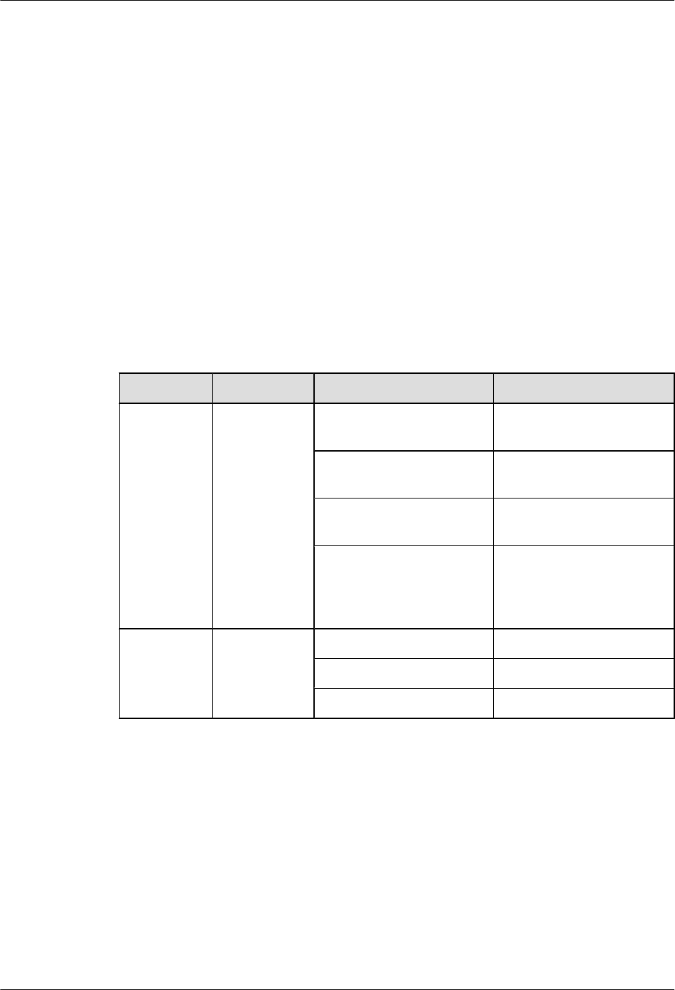
lThe fixing pieces are securely installed, and the backplanes are properly fixed without
distortion.
lThe power cable, grounding cable, optical fiber, alarm cable, and RF feeder are intact.
lThe power cable is not short-circuited or inversely connected, and the grounding cable is
not short-circuited.
lThe optical fiber, alarm cable, and RF jumper are correctly connected and fixed.
lIf the -48 V DC power supply is used, the external input voltage should be -37 V DC to
-60 V DC.
Procedure
Step 1 Switch on the external power supply equipment of the RRU3606.
Step 2 Check the status of the indicators in the cabling cavity. Table 1-16 lists the meanings of the
indicators.
Table 1-15 Meanings of the indicators
Indicator Color Status Meaning
RUN Green ON There is power input, but the
RRU3606 is faulty.
OFF There is no power input, or
the RRU3606 is faulty.
ON for 1 second and OFF
for 1 second
The RRU3606 is working
properly.
ON for 0.5 second and OFF
for 0.5 second
The RRU3606 software is
being loaded, or the data of
the RRU3606 is not
configured.
ALM Red ON Fatal alarm
Blinking at 0.5 Hz Minor alarm
OFF No alarm
----End
Powering Off the RRU3606
This describes how to power off the RRU3606.
Background
You need to power off the RRU3606 on special occasions, for example, when the equipment is
to be transferred to another site, the RRU3606 and cables need to be replaced, or the equipment
is subject to damage resulting from fires, smoke, and water.
1 RRU3606 User Guide
1-102 Huawei Proprietary and Confidential
Copyright © Huawei Technologies Co., Ltd.
Issue ()

Procedure
Switch off the external power supply equipment of the RRU3606.
----End
1.4.3 Replacing the RRU3606
This describes how to replace a faulty RRU3606.
Preparations
lDetermine the quantity of RRU3606s that need to be replaced and get ready new
RRU3606s.
lRecord the installation positions of the RRU3606s.
lRecord the positions of the screws used to fix the RRU3606s.
lRecord the positions of the ports of all the cables connected to the RRU3606s.
lGet ready wire nippers, bundling tape, an antistatic wrist strap or antistatic gloves, a Phillips
screwdriver, a straight screwdriver, and a wrench.
Procedure
Step 1 Record the information of the carriers.
Run the DSP CBTSSECTORCARRIERINFO command to query the cell IDs, sector IDs, and
carrier IDs.
Step 2 Block the carriers.
1. Run the BLK RES command to block all the carriers of the sectors where the RRU3606s
to be replaced are configured. It is recommended that you set the value of the priority
parameter to Low.
2. Run the DSP RES command to query whether the carriers are blocked. If they are blocked,
proceed with the next step.
Step 3 Power off the RRU3606s.
Step 4 Remove the RRU3606s to be replaced.
lRemove all the cables connected to the RRU3606s and take appropriate insulation measures.
lFor each RRU3606 to be replaced, remove the two M6x20 screws that are fixed in the
installation holes at the bottom of the backplane.
lRemove the hooks of the mounting brackets from the slots in the backplanes, and then remove
the RRU3606s from the backplanes.
lFor each RRU3606 to be replaced, remove the three M6x20 screws used to fix the mounting
bracket.
Step 5 Install the news RRU3606s.
lTake out the new RRU3606s.
lFor each new RRU3606, use three M6x20 screws to fix the mounting bracket.
lFor each new RRU3606, fit the hooks on the mounting bracket into the slots in the backplane.
lFor each new RRU3606, install two M6x20 screws in the installation holes at the bottom of
the backplane, and then fasten the screws.
1 RRU3606 User Guide
Issue () Huawei Proprietary and Confidential
Copyright © Huawei Technologies Co., Ltd.
1-103
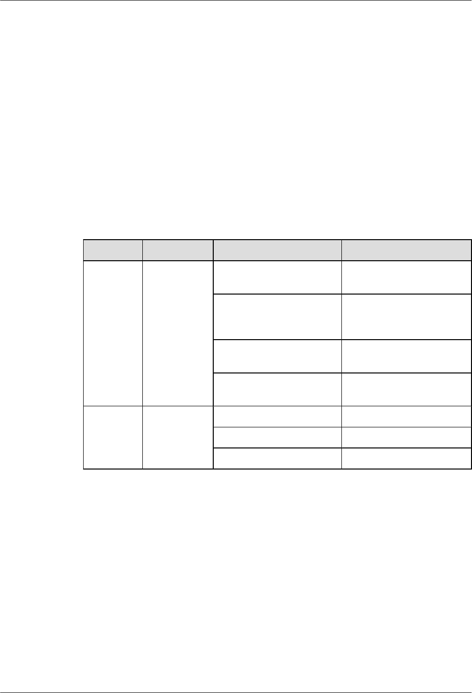
lConnect all the cables to the RRU3606s.
lVerify the installation, and then power on the RRU3606s.
Step 6 Load the software.
If automatic loading is configured for the RRU3606s, the CPU software and FPGA software of
the RRU3606s are automatically loaded from the BAM after the RRU3606s are powered on. If
automatic loading is not configured, you need to run the DLD CBTSSW command to load the
CPU software and FPGA software of the RRU3606s.
Step 7 Unblock the carriers.
Run the UBL RES command to unblock the carriers.
Step 8 Check that the RRU3606s work properly.
Observe the running and alarm indicators of the RRU3606s. Table 1-16 lists the running and
alarm indicators of the RRU3606.
Table 1-16 Running and alarm indicators of the RRU3606
Indicator Color State Description
RUN Green ON The power input is normal,
but the board is faulty.
OFF There is no power input, or
the RRU3606 is working in
alarm mode.
ON for 1 second and OFF for
1 second
The board is working
properly.
ON for 0.5 second and OFF
for 0.5 second
The board software is being
loaded.
ALM Red ON Fatal alarm
Blinking at 0.5 Hz Minor alarm
OFF No alarm
----End
1.4.4 Replacing the Cables of the RRU3606
This describes how to replace the cables of the RRU3606. The power cable, RF cable, optical
fiber, and alarm cable of the RRU3606 can be replaced on site.
1.4.4.1 Replacing the Power Cable of the RRU3606
This describes how to replace the power cable of the RRU3606.
1.4.4.2 Replacing the RF Jumper of the RRU3606
This describes how to replace faulty RF jumpers of the RRU3606.
1.4.4.3 Replacing the Optical Fiber of the RRU3606
This describes how to replace faulty optical fibers of the RRU3606.
1 RRU3606 User Guide
1-104 Huawei Proprietary and Confidential
Copyright © Huawei Technologies Co., Ltd.
Issue ()

1.4.4.4 Replacing the Alarm Cables of the RRU3606
This describes how to replace faulty alarm cables of the RRU3606.
Replacing the Power Cable of the RRU3606
This describes how to replace the power cable of the RRU3606.
Prerequisite
lGet ready a new power cable.
lRecord the installation of the power supply unit.
lGet ready wire nippers, bundling tape, an antistatic wrist strap or antistatic gloves, a Phillips
screwdriver, a straight screwdriver, and a wrench.
Procedure
Step 1 Route the new power cable in the same way as the faulty power cable is routed.
Step 2 Run the DSP CBTSSECTORCARRIERINFO command to query the cell IDs, sector IDs, and
carrier IDs.
Step 3 Block the carriers.
1. Run the BLK RES command to block all the carriers of the sector where the power cable
to be replaced is configured. It is recommended that you set the value of the priority
parameter to Low.
2. Run the DSP RES command to query whether the carriers are blocked. If they are blocked,
proceed with the next step.
Step 4 Remove the faulty power cable.
1. Switch off the external power supply equipment of the RRU3606.
2. Open the cover of the cabling cavity and the cover above the power cable input terminal.
3. Loosen the screw at the cable clip (marked PGND) of the power cable.
4. In the cabling cavity, remove the OT terminal of the faulty power cable, and then remove
the faulty power cable.
Step 5 Install the new power cable.
lInstall the OT terminal of the new power cable.
lUse the cable clip to fix the exposed part of the shielding layer, and then fasten the screw.
lClose the cover above the power cable input terminal and the cover of the cabling cavity.
Step 6 Switch on the external power supply equipment of the RRU3606.
Step 7 Block the carriers.
Run the UBL RES command to unblock all the carriers of the sector where the power cable is
configured.
Step 8 Check that the RRU3606s work properly.
Observe the running and alarm indicators of the RRU3606s. Table 1-17 lists the running and
alarm indicators of the RRU3606.
1 RRU3606 User Guide
Issue () Huawei Proprietary and Confidential
Copyright © Huawei Technologies Co., Ltd.
1-105
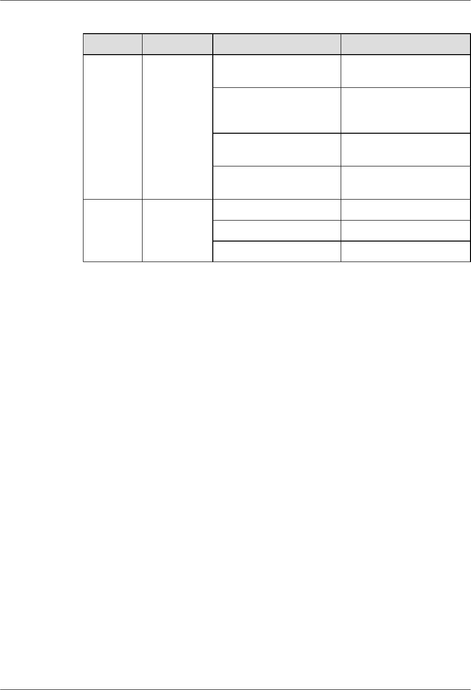
Table 1-17 Running and alarm indicators of the RRU3606
Indicator Color State Description
RUN Green ON The power input is normal,
but the board is faulty.
OFF There is no power input, or
the RRU3606 is working in
alarm mode.
ON for 1 second and OFF for
1 second
The board is working
properly.
ON for 0.5 second and OFF
for 0.5 second
The board software is being
loaded.
ALM Red ON Fatal alarm
Blinking at 0.5 Hz Minor alarm
OFF No alarm
----End
Postrequisite
Keep the faulty power cable properly, and then clean up the site.
Replacing the RF Jumper of the RRU3606
This describes how to replace faulty RF jumpers of the RRU3606.
Prerequisite
lDetermine the quantity of the RF jumpers to be replaced and their types, and then get ready
new jumpers.
lGet ready a wrench, a feeder cutter, cutting nippers (matching the feeder types), an antistatic
wrist strap or antistatic gloves, and a screwdriver.
Procedure
Step 1 Run the DSP CBTSSECTORCARRIERINFO command to query the cell IDs, sector IDs, and
carrier IDs.
Step 2 Block the carriers.
1. Run the BLK RES command to block all the carriers of the sectors where the jumpers to
be replaced are configured. It is recommended that you set the value of the priority
parameter to Low.
2. Run the DSP RES command to query whether the carriers are blocked. If they are blocked,
proceed with the next step.
Step 3 Remove the faulty RF jumpers.
1 RRU3606 User Guide
1-106 Huawei Proprietary and Confidential
Copyright © Huawei Technologies Co., Ltd.
Issue ()

1. Power off the RRU3606.
2. Remove the faulty RF jumpers from the RF jumper ports of the RRU3606.
3. Remove the faulty RF jumpers from the feeder ports.
Step 4 Install new RF jumpers.
1. Connect the DIN connectors of the new RF jumpers to the ANT_TX/RXA and ANT_RXB
ports of the RRU3606.
2. Connect the new RF jumpers to the feeders.
3. Use waterproof tape to protect the connection points at both ends of each RF jumper.
NOTE
lWrap each connection point with three layers of tape, and ensure that each layer covers at least
50% of the previous layer.
lEnsure that each layer of tape is evenly and tightly stretched. In this way, the tape does not get
loose.
4. Stick PVC insulation tape over the waterproof tape in the same way as you stick the
waterproof tape.
5. Power on the RRU3606.
Step 5 Unblock the carriers.
Run the UBL RES command to unblock all the carriers of the sectors where the RF jumpers to
be replaced are configured.
Step 6 Check that the new RF jumpers are functional.
Perform service verification and a calibration test on the carriers of the new RF jumpers. If the
results are normal and alarms are not generated, the replacement is successful. If the replacement
fails, start troubleshooting.
----End
Postrequisite
Keep the faulty power cable properly, and then clean up the site.
Replacing the Optical Fiber of the RRU3606
This describes how to replace faulty optical fibers of the RRU3606.
Prerequisite
lDetermine the quantity of the optical fibers to be replaced and their types, and then get
ready new jumpers.
lCheck that the new optical fibers are intact.
lRecord the installation positions of the optical fibers.
lGet ready an antistatic wrist strap or antistatic gloves, a Philips screwdriver, a straight
screwdriver, an antistatic box or bag, dust-free cloth, a fiber cleaning box, a cable cutter,
and tape.
1 RRU3606 User Guide
Issue () Huawei Proprietary and Confidential
Copyright © Huawei Technologies Co., Ltd.
1-107
CAUTION
lAfter an optical fiber is removed from the optical module, do not look at the light beam with
naked eyes.
lWhen the optical fiber in the CPRI port, all the services carried by the optical fiber are
interrupted.
Procedure
Step 1 Run the DSP CBTSSECTORCARRIERINFO command to query the cell IDs, sector IDs, and
carrier IDs of the RRU3606s connected by the optical fibers to be replaced.
Step 2 Block the carriers.
1. Run the BLK RES command to block all the carriers of the sectors where the optical fibers
to be replaced are configured. It is recommended that you set the value of the priority
parameter to Low.
2. Run the DSP RES command to query whether the carriers are blocked. If they are blocked,
proceed with the next step.
Step 3 Remove the faulty optical fibers.
1. Wear antistatic gloves.
2. Route the new optical fibers to the peer equipment as the faulty optical fibers are routed.
3. Press the protruding part of the connector of each optical fiber, and then remove the
connector from the optical module.
Step 4 Install the new optical fibers.
1. According to the labels on the new optical fibers, insert the new optical fibers into the
optical modules.
2. Bundle the new optical fibers.
Step 5 Unblock the carriers.
Run the UBL RES command to unblock all the carriers of the RRU3606s connected by the
optical fibers.
Step 6 Check that the new optical fibers work properly.
Observe the indicators of optical ports and ensure that the new optical fibers work properly.
Table 1-18 lists the indicators of optical ports.
Table 1-18 Indicators of optical ports
Indicator Color State Description
CPRI_W Red and green Green and ON The CPRI link is functional.
Red and ON An alarm is generated for
receiving by the optical
module (local LOS alarm).
Red, ON for 0.5 second and
OFF for 0.5 second
The CPRI is out of lock.
1 RRU3606 User Guide
1-108 Huawei Proprietary and Confidential
Copyright © Huawei Technologies Co., Ltd.
Issue ()

Indicator Color State Description
OFF The optical module is not in
position or powered off.
CPRI_E Red and green Green and ON The CPRI link is functional.
Red and ON An alarm is generated for
receiving by the optical
module (local LOS alarm).
Red, ON for 0.5 second and
OFF for 0.5 second
CPRI lock lost
OFF The optical module is not in
position or powered off.
----End
Postrequisite
Keep the faulty optical fibers properly, and then clean up the site.
Replacing the Alarm Cables of the RRU3606
This describes how to replace faulty alarm cables of the RRU3606.
Prerequisite
lGet ready new alarm cables.
lRecord the installation positions of the alarm cables.
lGet ready a cable cutter, an antistatic wrist strap or antistatic gloves, a screwdriver, and
bundling tape.
Procedure
Step 1 Remove the faulty alarm cables.
1. Route the new alarm cables as the faulty alarm cables are routed.
2. Open the cover of the cabling cavity.
3. Remove the alarm cable connectors connected to the RS485 and EXT_ALM ports in the
cabling cavity, and then remove the faulty alarm cables.
Step 2 Route the new alarm cables along the cabling trough in the cabling cavity, and then connect the
alarm cables to the RS485 and EXT_ALM ports.
Step 3 Take waterproofing and sealing measures.
----End
Postrequisite
Keep the faulty power cable properly, and then clean up the site.
1 RRU3606 User Guide
Issue () Huawei Proprietary and Confidential
Copyright © Huawei Technologies Co., Ltd.
1-109