Huawei Technologies RRU3606-AWS-CL Radio Remote Unit User Manual
Huawei Technologies Co.,Ltd Radio Remote Unit
UserManual.wiki
>
Huawei Technologies
>
RRU3606 AWS CL User Manual
Users Manual
Navigation menu
Upload a User Manual
Namespaces
Wiki Guide
HTML
PDF
Info
Views
User Manual
Discussion / Help
Navigation
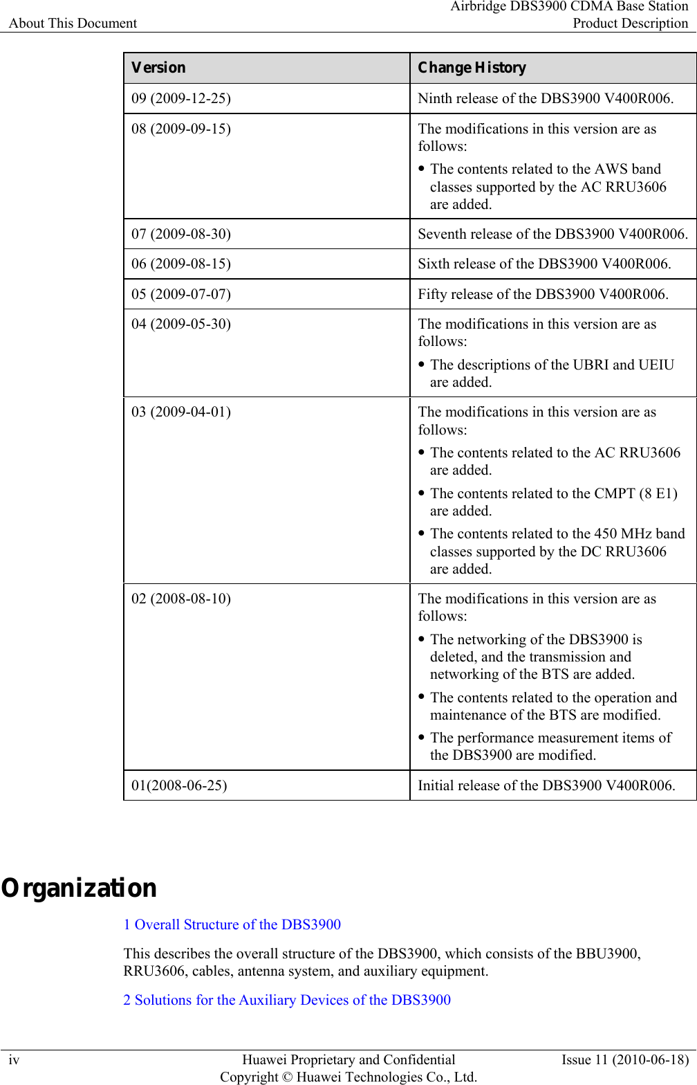
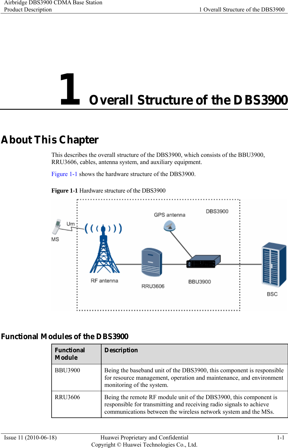
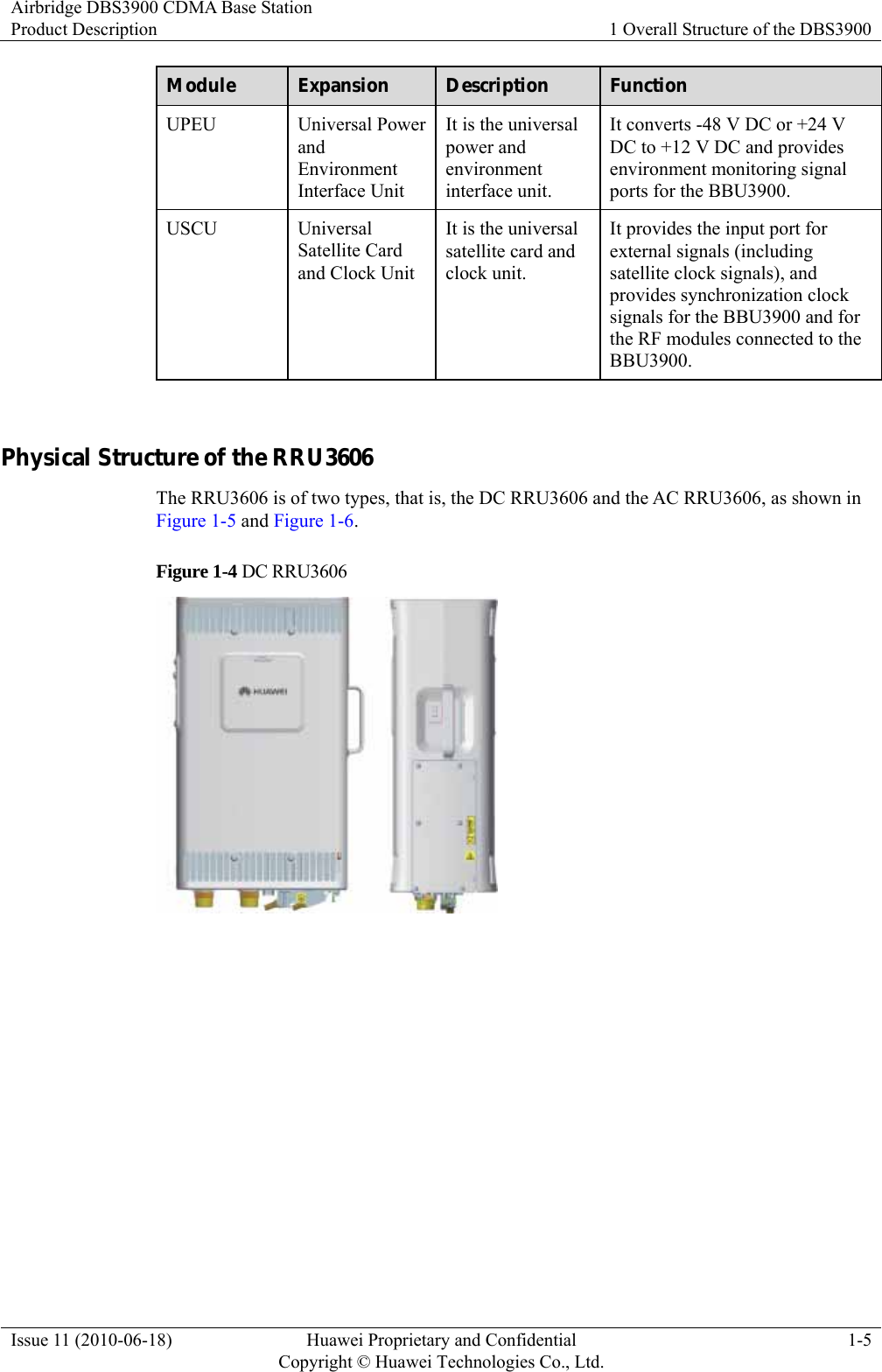
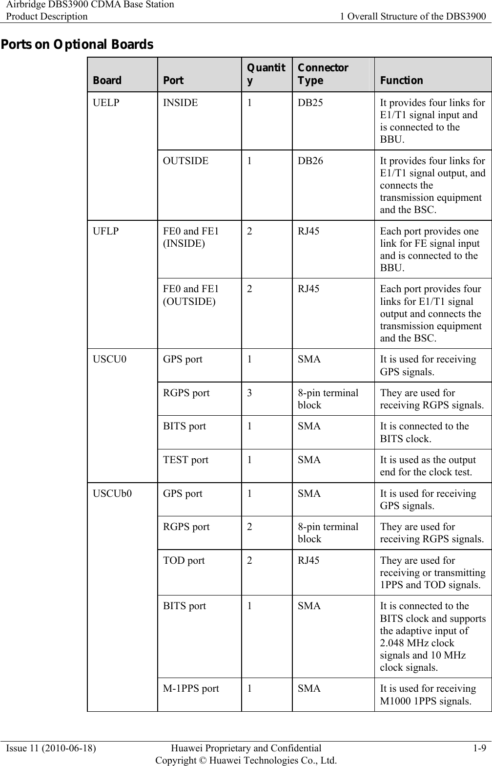
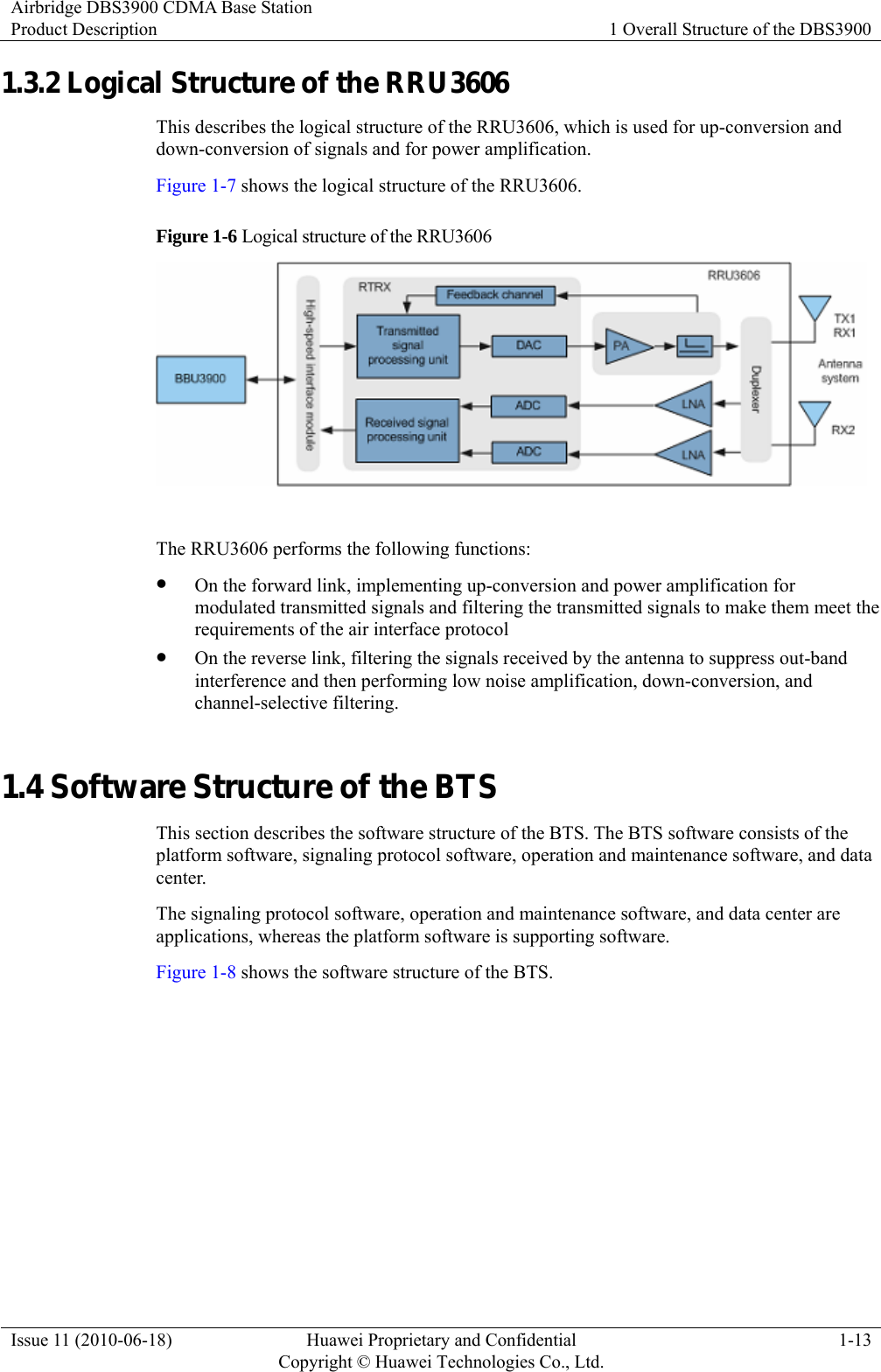
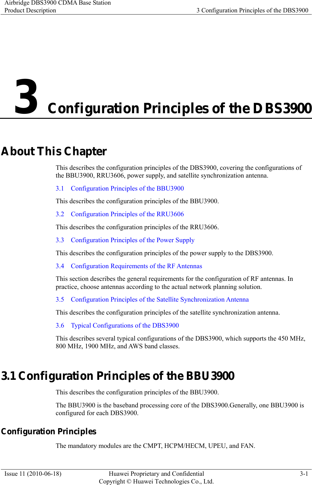
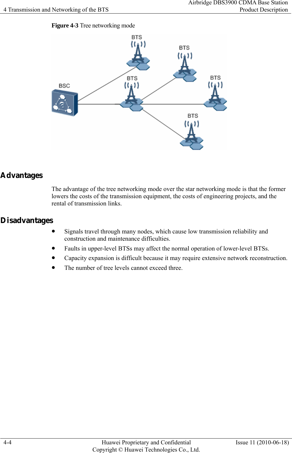
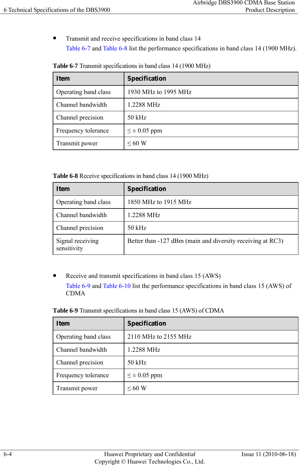
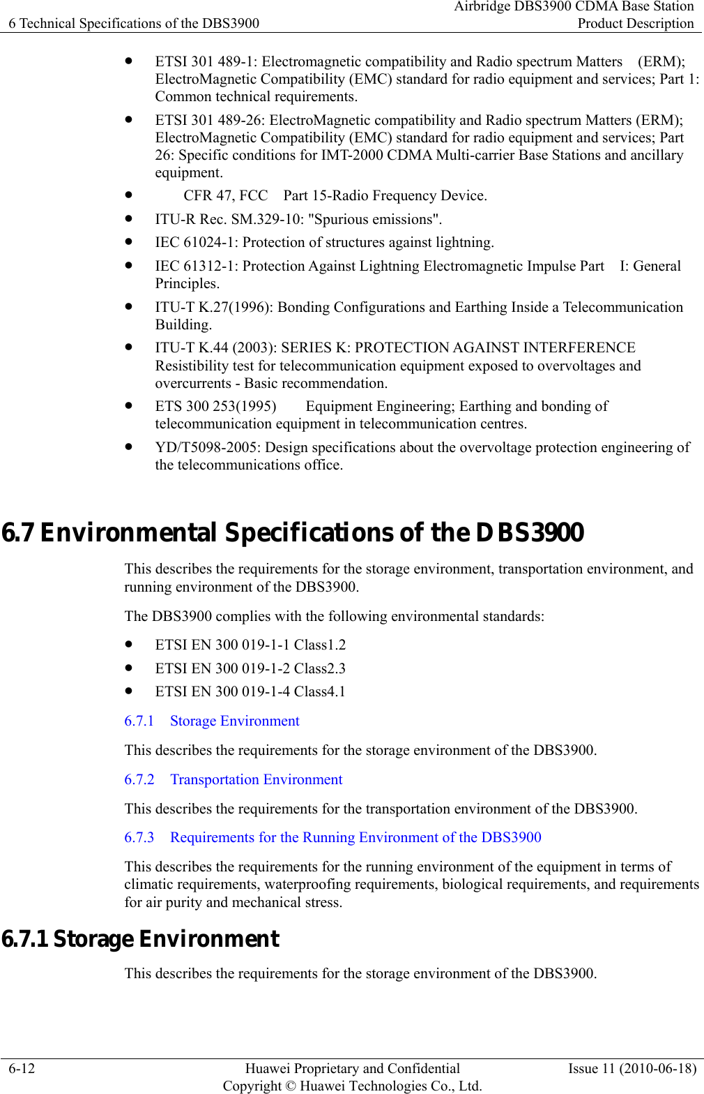
![About This Document Airbridge DBS3900 CDMA Base StationProduct Description vi Huawei Proprietary and Confidential Copyright © Huawei Technologies Co., Ltd.Issue 11 (2010-06-18) General Conventions Convention Description Times New Roman Normal paragraphs are in Times New Roman. Boldface Names of files, directories, folders, and users are in boldface. For example, log in as user root. Italic Book titles are in italics. Courier New Terminal display is in Courier New. Command Conventions Convention Description Boldface The keywords of a command line are in boldface. Italic Command arguments are in italics. [ ] Items (keywords or arguments) in square brackets [ ] are optional. { x | y | ... } Alternative items are grouped in braces and separated by vertical bars. One is selected. [ x | y | ... ] Optional alternative items are grouped in square brackets and separated by vertical bars. One or none is selected. { x | y | ... } * Alternative items are grouped in braces and separated by vertical bars. A minimum of one or a maximum of all can be selected. GUI Conventions Convention Description Boldface Buttons, menus, parameters, tabs, windows, and dialog titles are in boldface. For example, click OK. > Multi-level menus are in boldface and separated by the ">" signs. For example, choose File > Create > Folder. Keyboard Operation Format Description Key Press the key. For example, press Enter and press Tab.](https://usermanual.wiki/Huawei-Technologies/RRU3606-AWS-CL/User-Guide-1308550-Page-6.png)
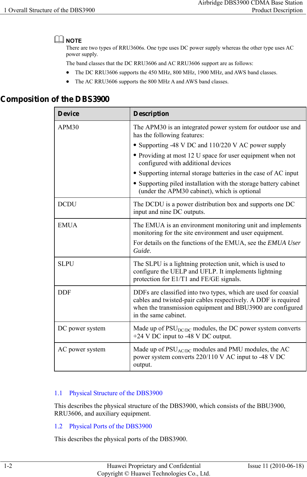
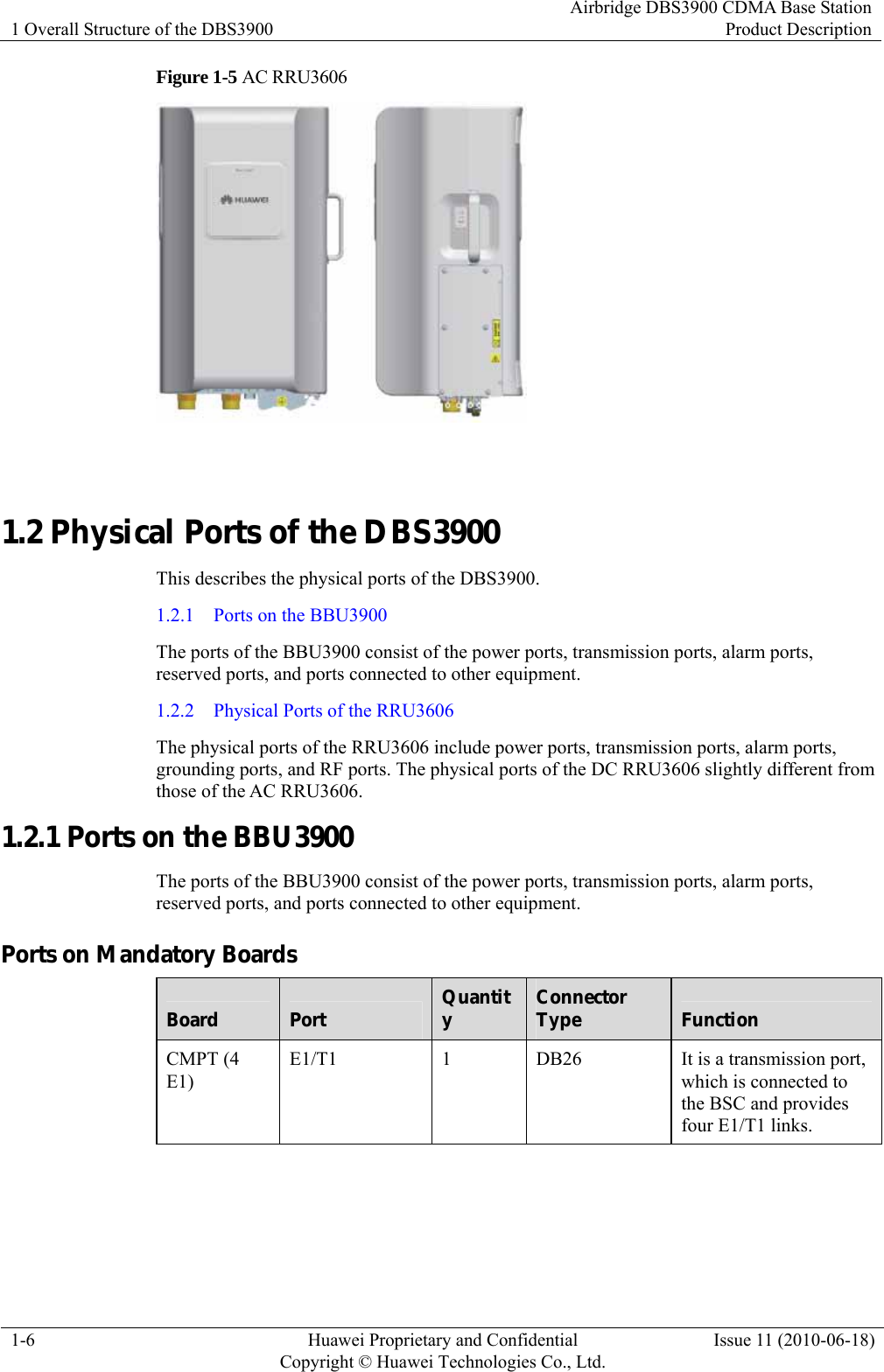
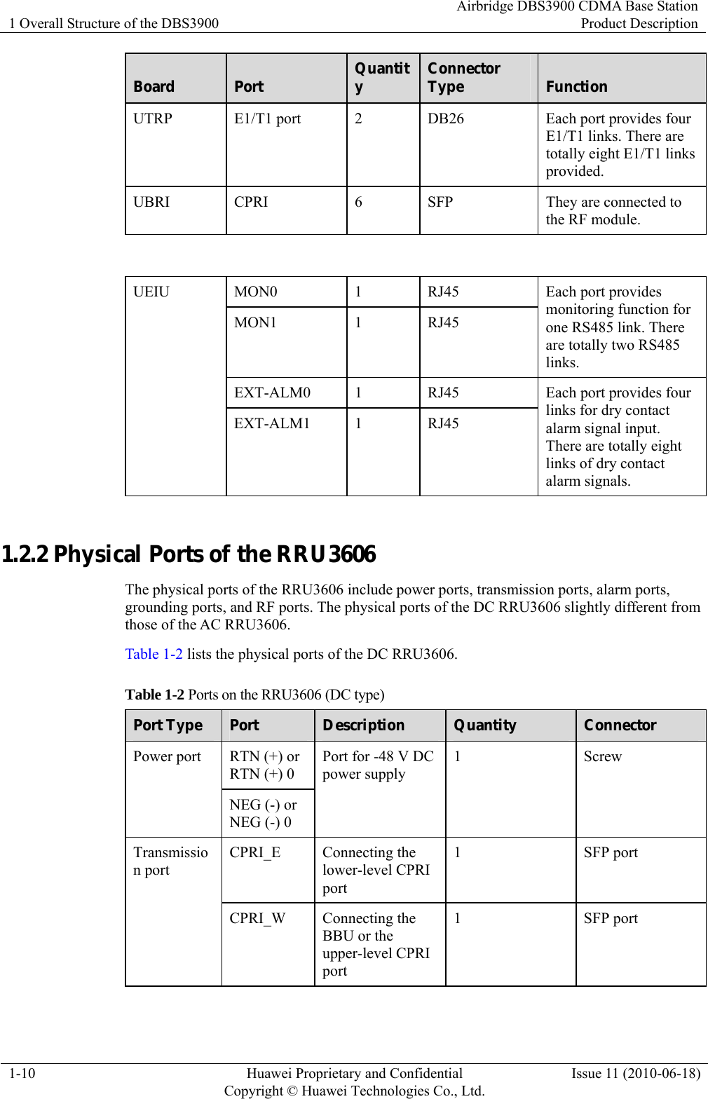
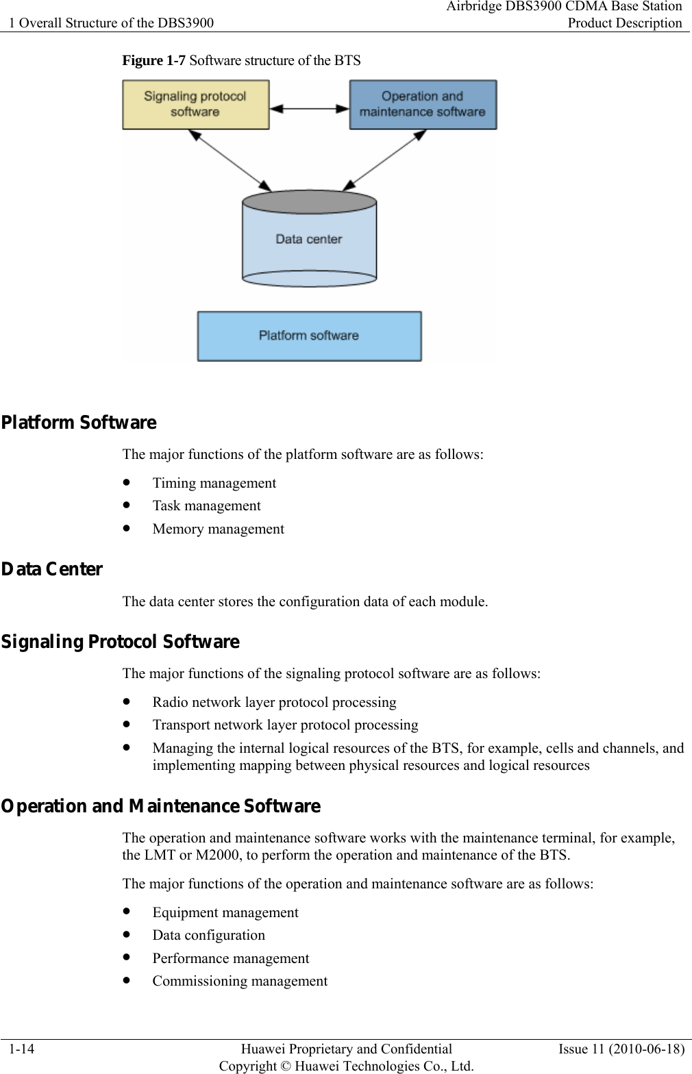
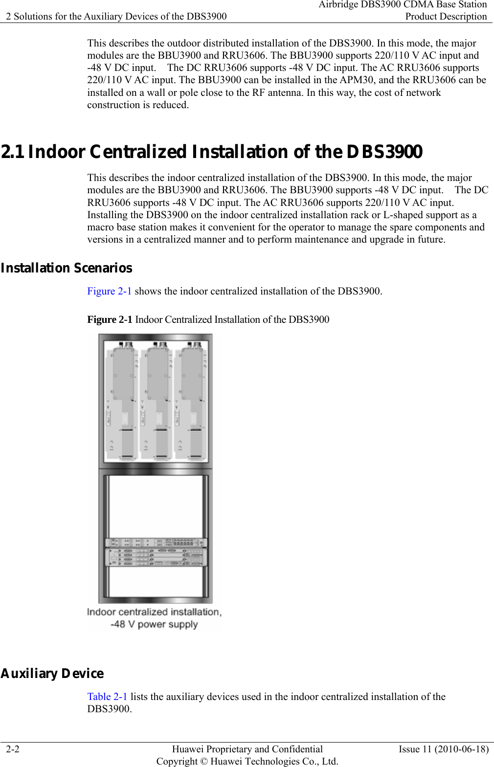
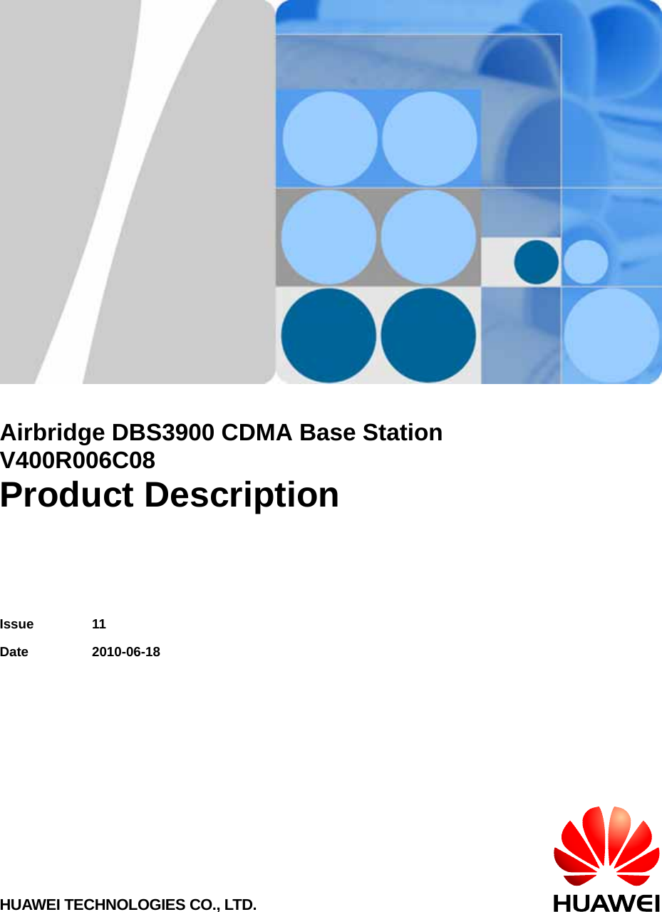
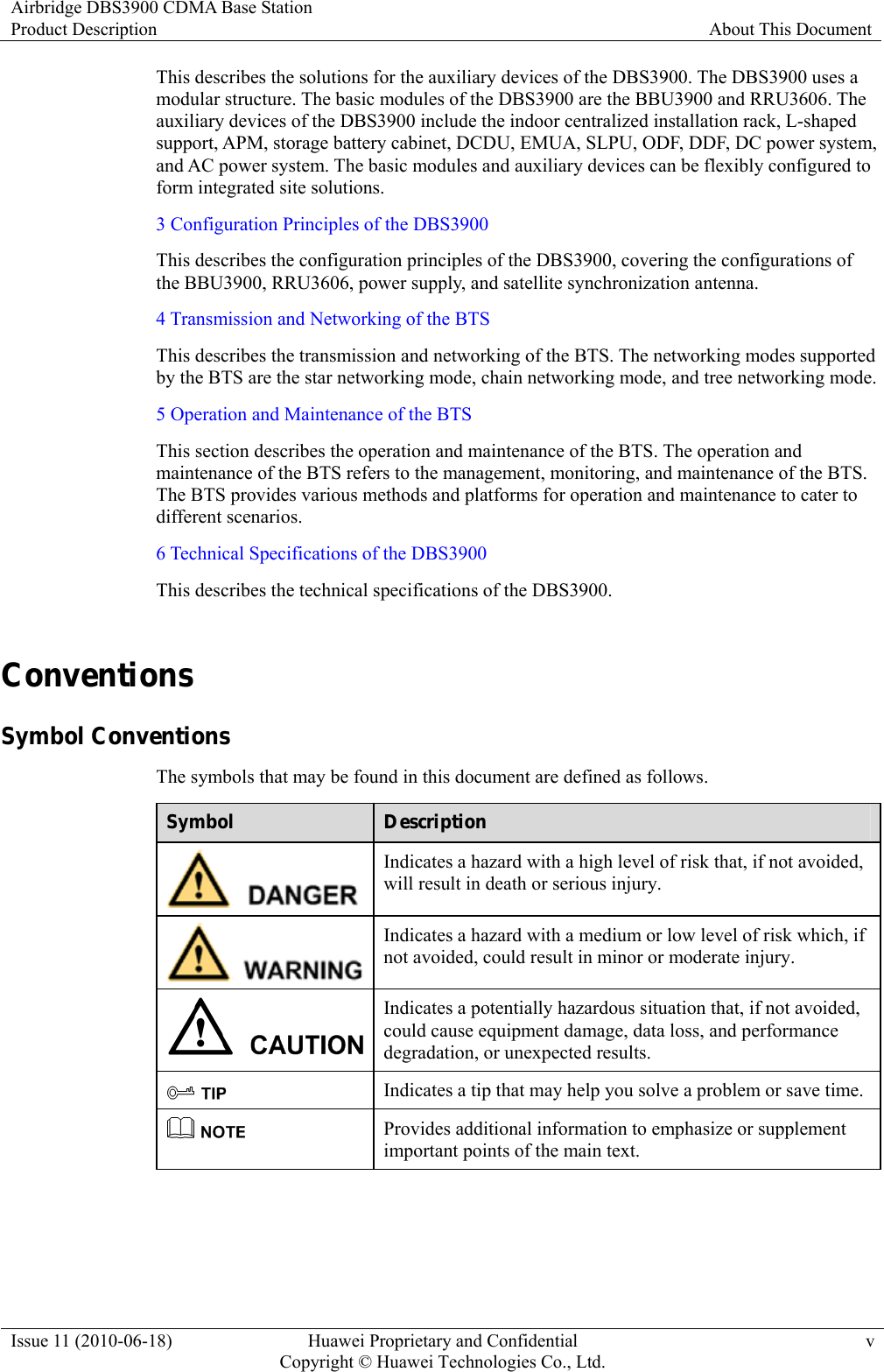
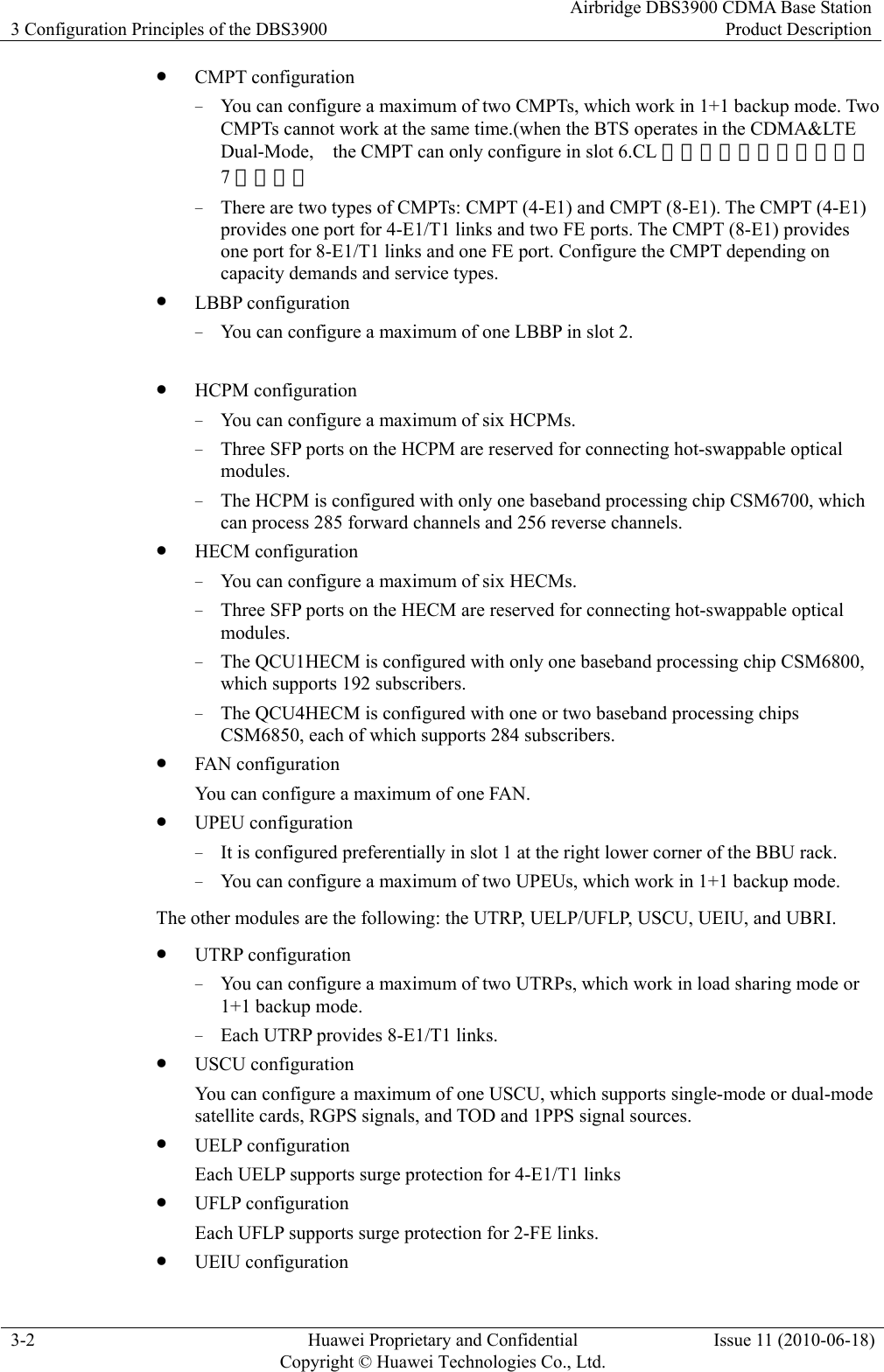
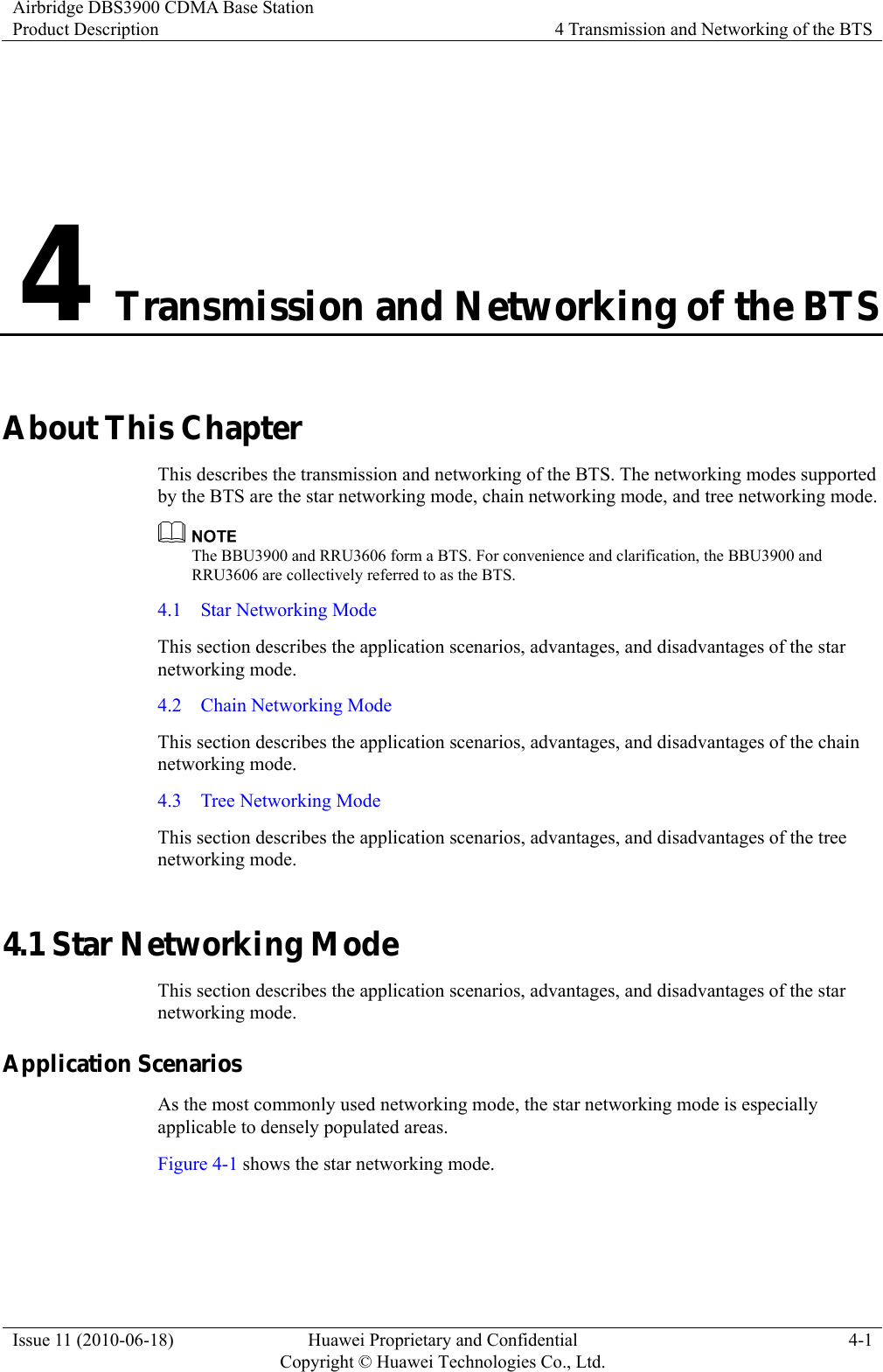
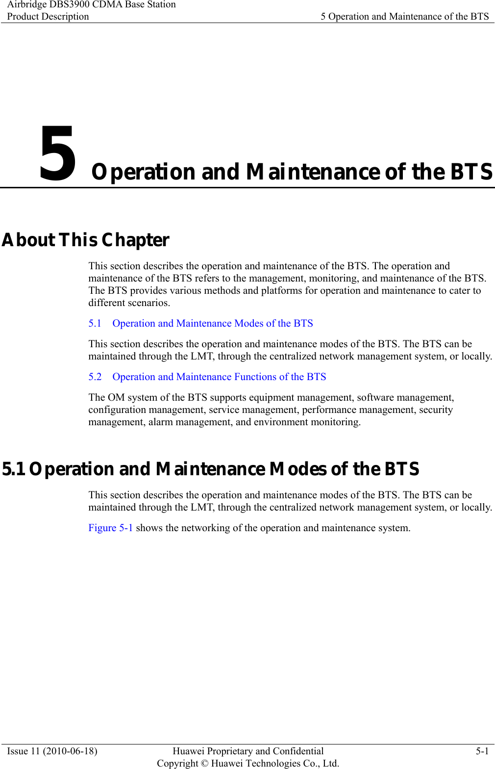
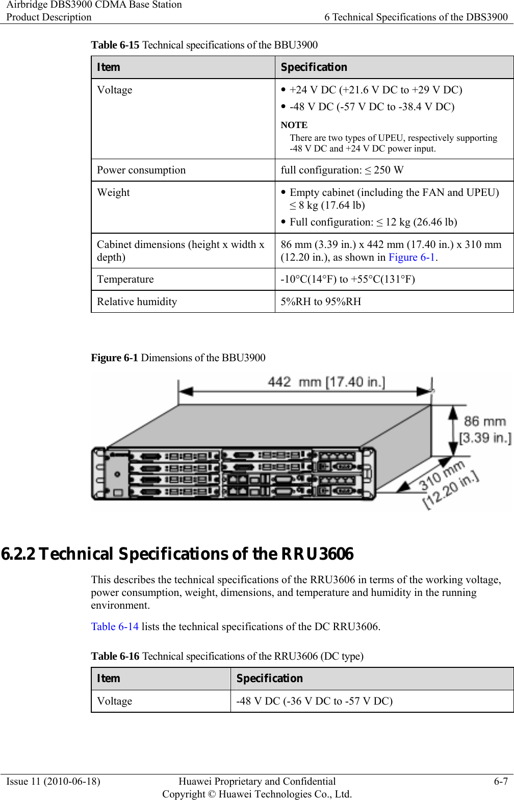
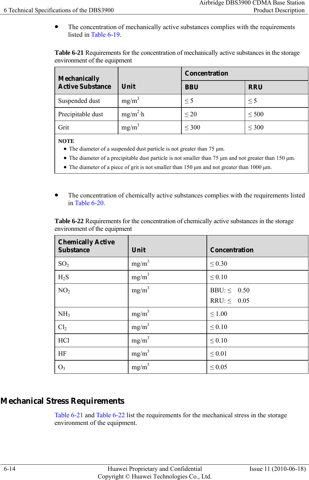
![2 Solutions for the Auxiliary Devices of the DBS3900 Airbridge DBS3900 CDMA Base StationProduct Description 2-4 Huawei Proprietary and Confidential Copyright © Huawei Technologies Co., Ltd.Issue 11 (2010-06-18) Figure 2-2 Indoor distributed installation Auxiliary Device Table 2-2 lists the auxiliary devices used in the indoor distributed installation of the DBS3900. Table 2-2 Auxiliary devices used in the door distributed installation of the DBS3900 Component Description Indoor centralized installation rack or L-shaped support The indoor centralized installation rack or L-shaped support is used for the BBU3900 and RRU3606 respectively. The indoor centralized installation rack can be installed on the ground, on a wall, or in a piled way. The L-shaped support can be installed on the ground. DCDU The DCDU is a DC power distribution box and supports one -48 V power input and multiple -48 V outputs. z If the distance between the RRU3606 and the BBU3900 exceeds 70 m [229.66 ft], independent power supply equipment needs to be configured for the RRU3606. z The auxiliary devices should be configured according to the actual situation in the equipment room. 2.3 Outdoor Centralized Installation of the DBS3900 This describes the outdoor centralized installation of the DBS3900. In this mode, the major modules are the BBU3900 and RRU3606. The BBU3900 supports 220/110 V AC and -48 V DC power input. The DC RRU3606 supports -48 V DC power input. The AC RRU3606](https://usermanual.wiki/Huawei-Technologies/RRU3606-AWS-CL/User-Guide-1308550-Page-31.png)
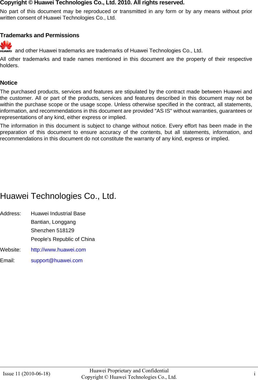
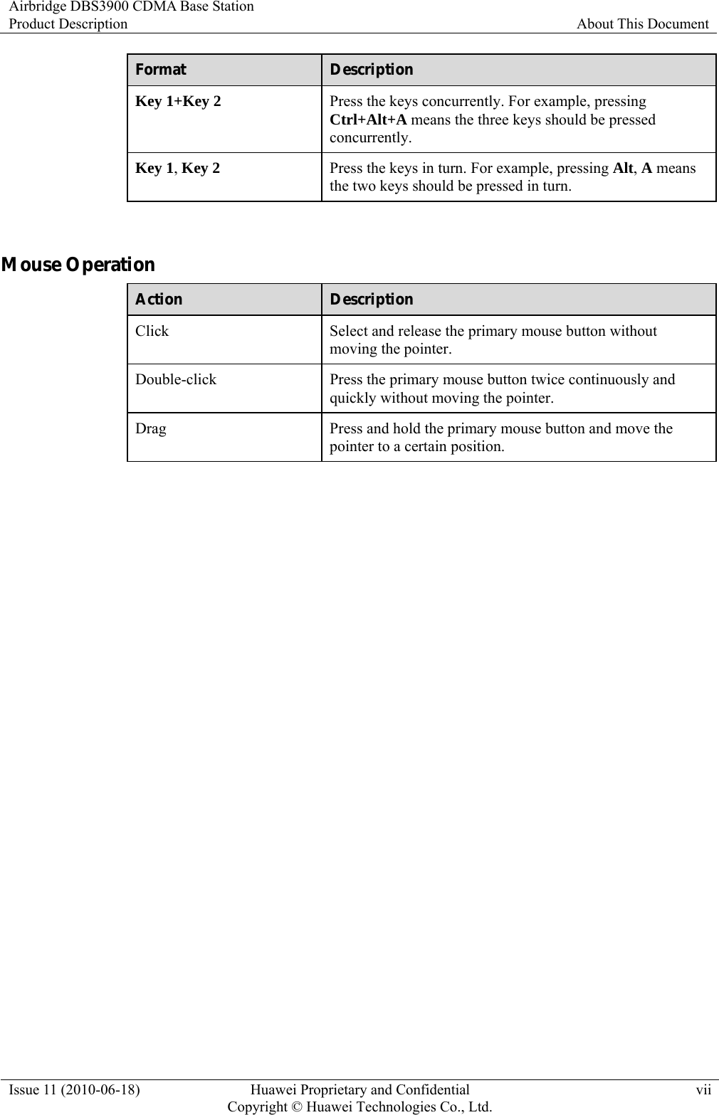
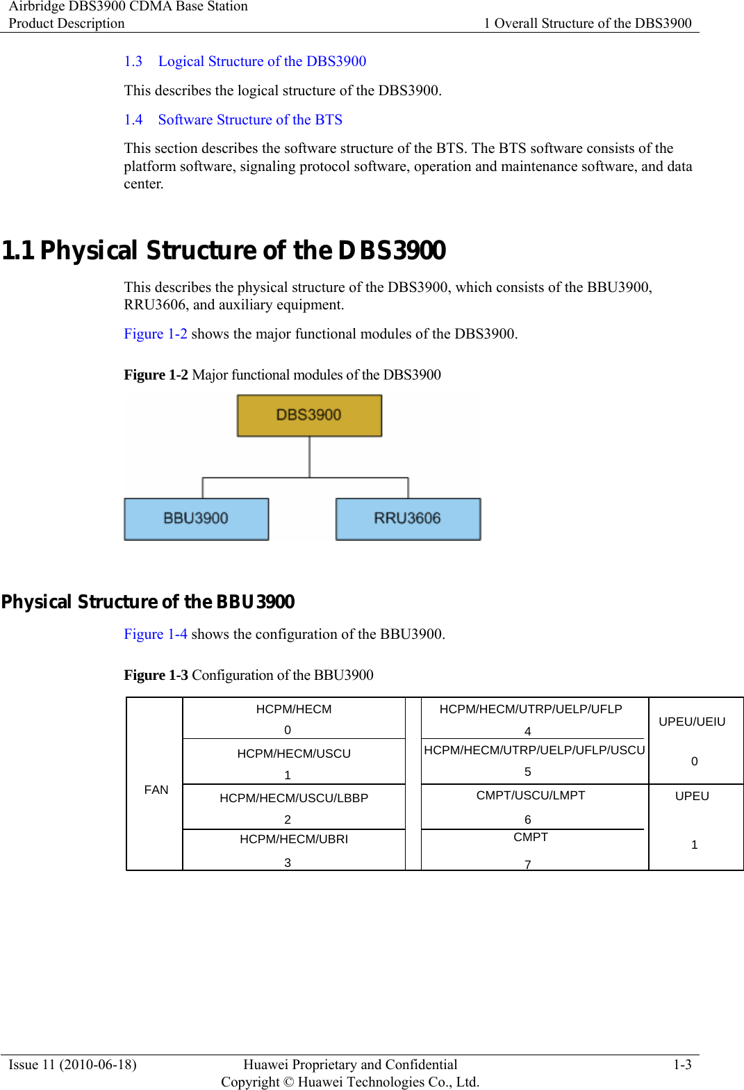
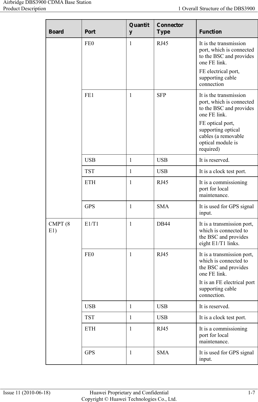
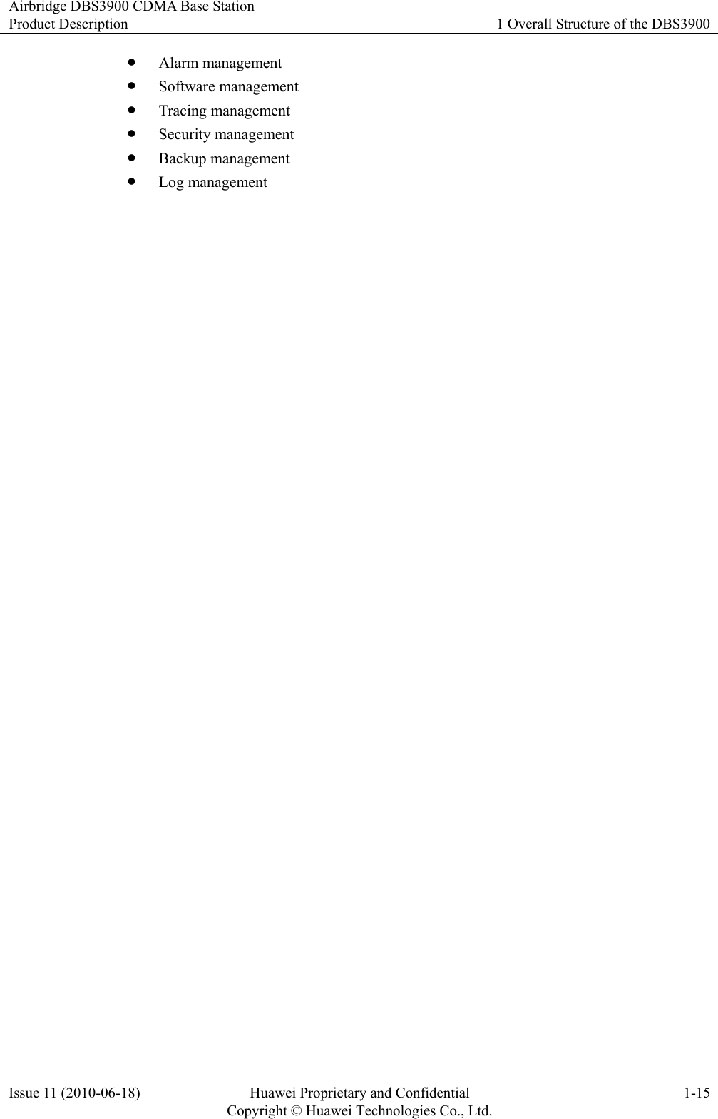
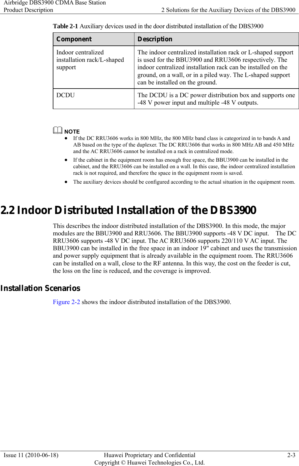
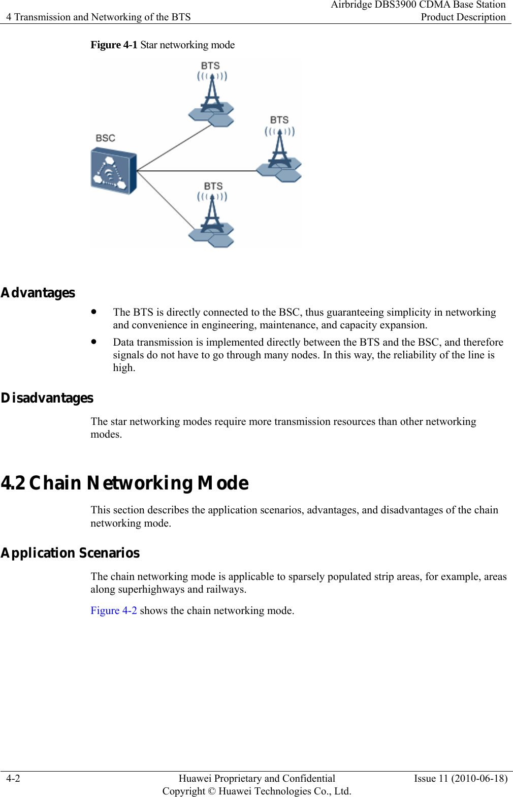
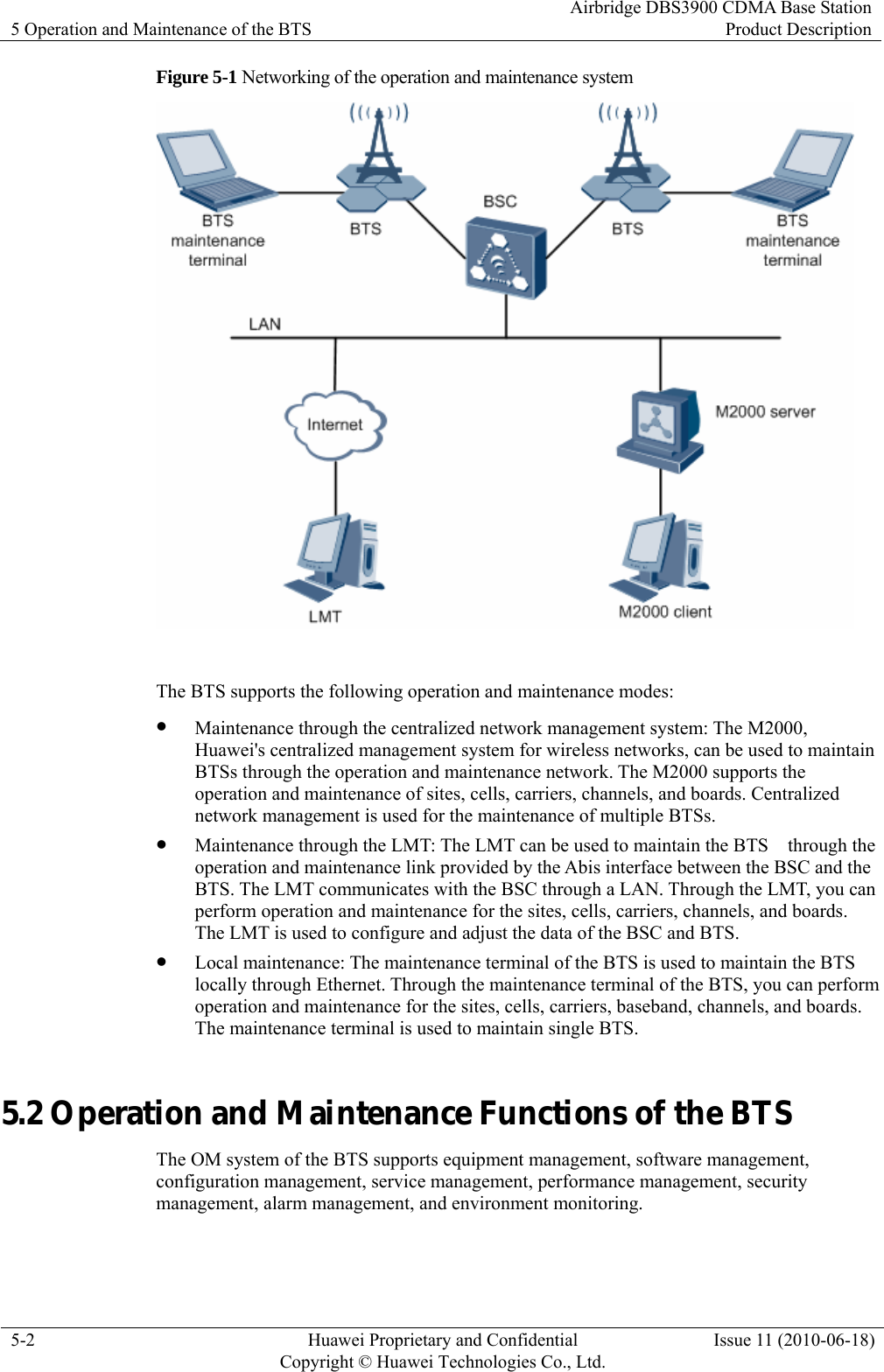
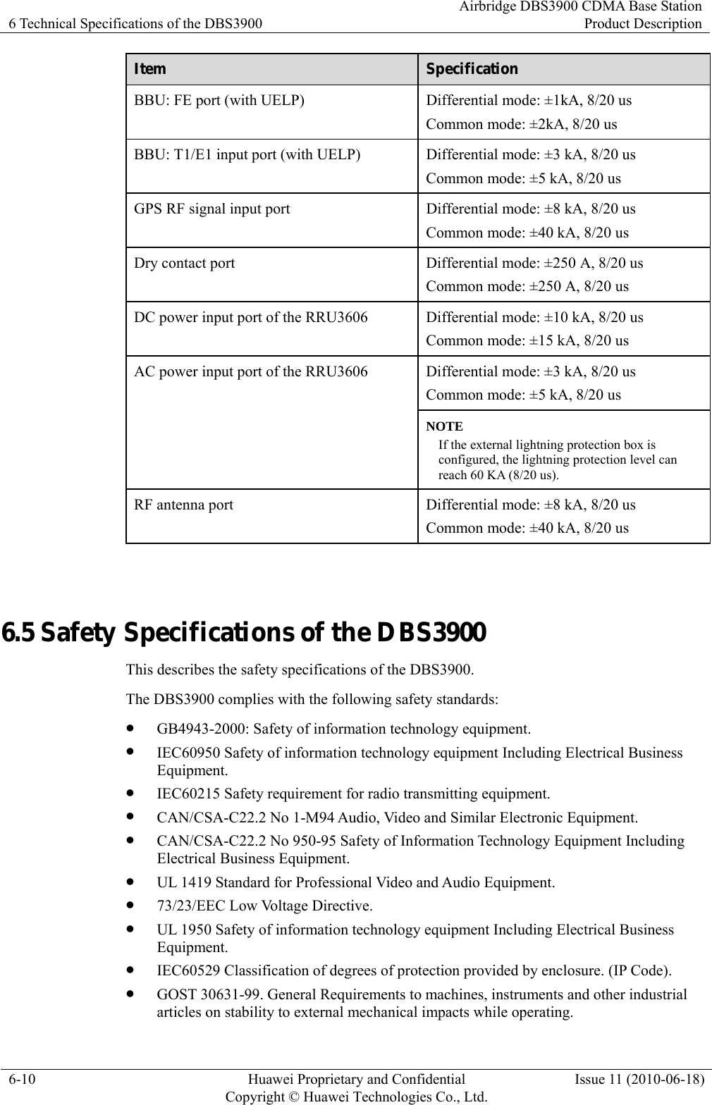
![2 Solutions for the Auxiliary Devices of the DBS3900 Airbridge DBS3900 CDMA Base StationProduct Description 2-6 Huawei Proprietary and Confidential Copyright © Huawei Technologies Co., Ltd.Issue 11 (2010-06-18) Table 2-3 Auxiliary devices used in the outdoor distributed installation of the DBS3900 Component Description APM30 (220/110 V AC type) The APM30 of the 220/110 V AC type is an integrated power system that is used for outdoor applications and supports 220/110 V AC power input. APM30 (-48 V DC type) The APM30 of the -48 V DC type is an integrated power backup system that is used for outdoor applications and supports -48 V DC power input. Storage battery cabinet This component is optional and used for power backup. When the mains supply fails, the storage battery cabinet powers the equipment. z If the distance between the RRU3606 and the BBU3900 exceeds 70 m [229.66 ft], independent power supply equipment needs to be configured for the RRU3606. z The auxiliary devices should be configured according to the actual situation and power input mode. z The DC RRU3606 that works in 800 MHz AB and 450 MHz and the AC RRU3606 cannot be installed in centralized mode. 2.4 Outdoor Distributed Installation of the DBS3900 This describes the outdoor distributed installation of the DBS3900. In this mode, the major modules are the BBU3900 and RRU3606. The BBU3900 supports 220/110 V AC input and -48 V DC input. The DC RRU3606 supports -48 V DC input. The AC RRU3606 supports 220/110 V AC input. The BBU3900 can be installed in the APM30, and the RRU3606 can be installed on a wall or pole close to the RF antenna. In this way, the cost of network construction is reduced. Installation Scenarios Figure 2-4 shows the outdoor distributed installation of the DBS3900.](https://usermanual.wiki/Huawei-Technologies/RRU3606-AWS-CL/User-Guide-1308550-Page-33.png)
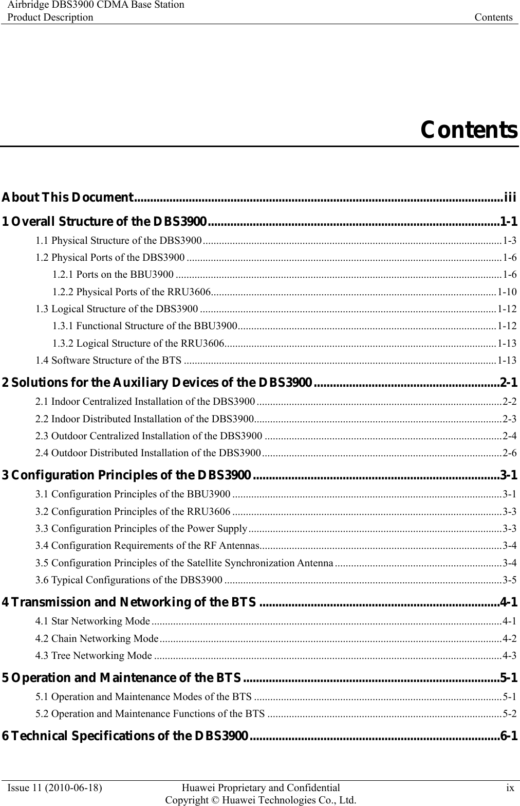
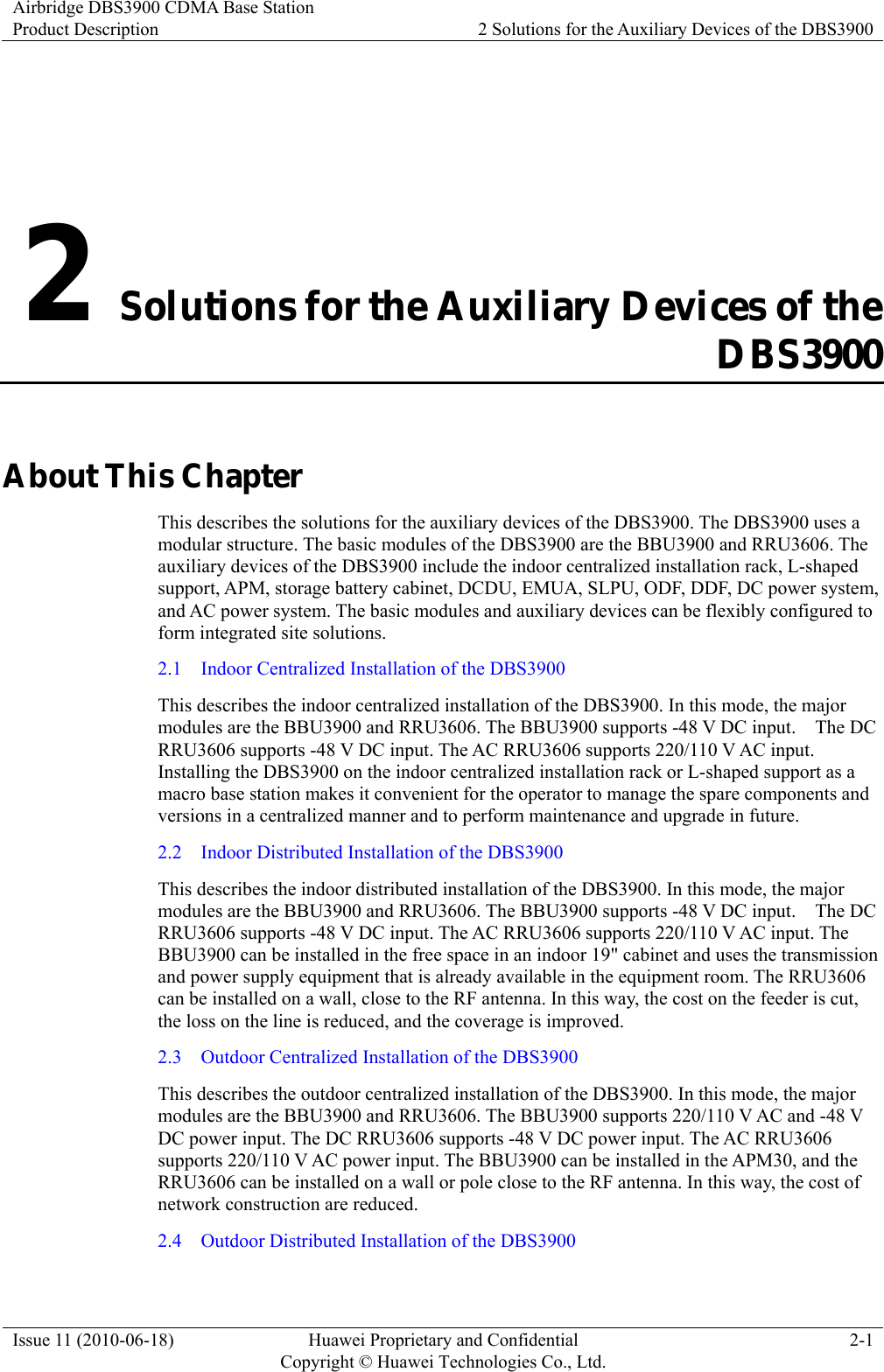
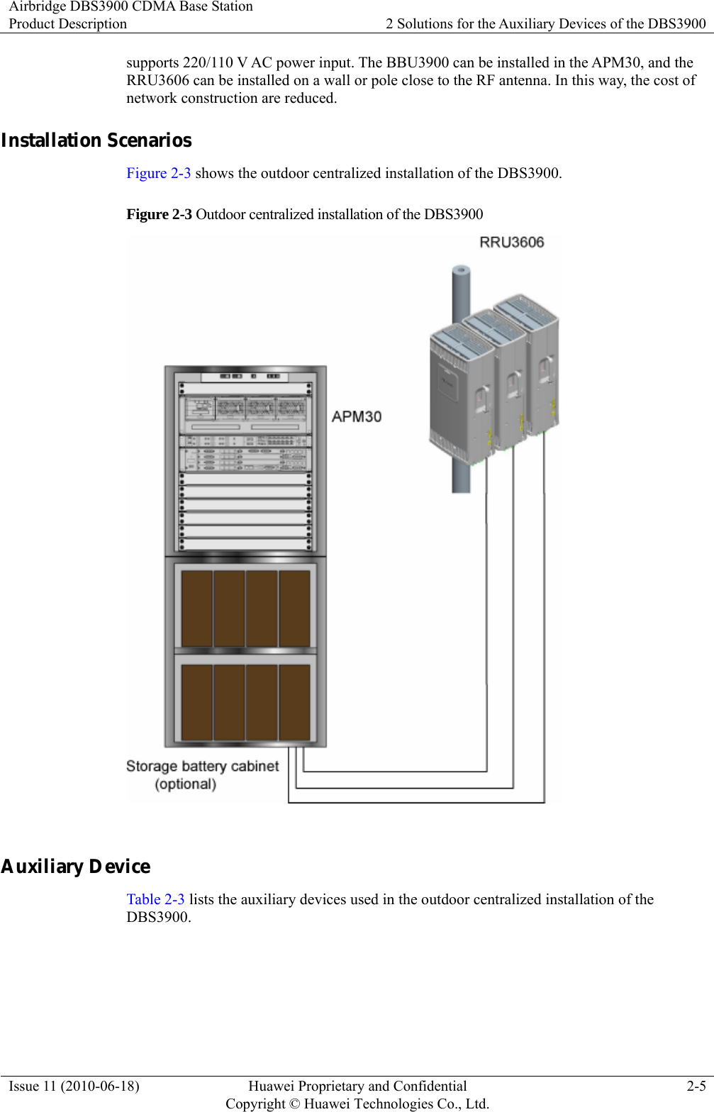
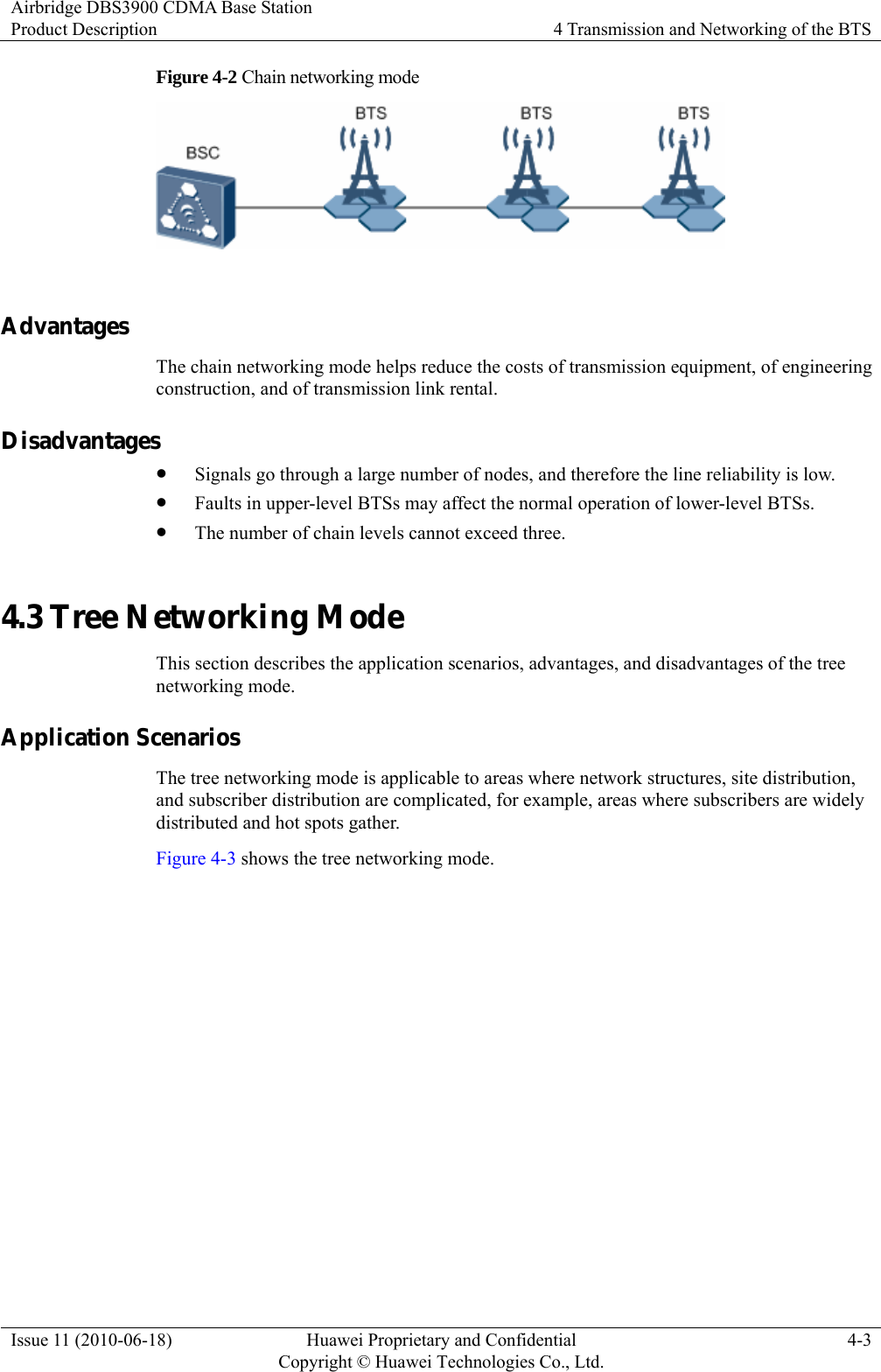
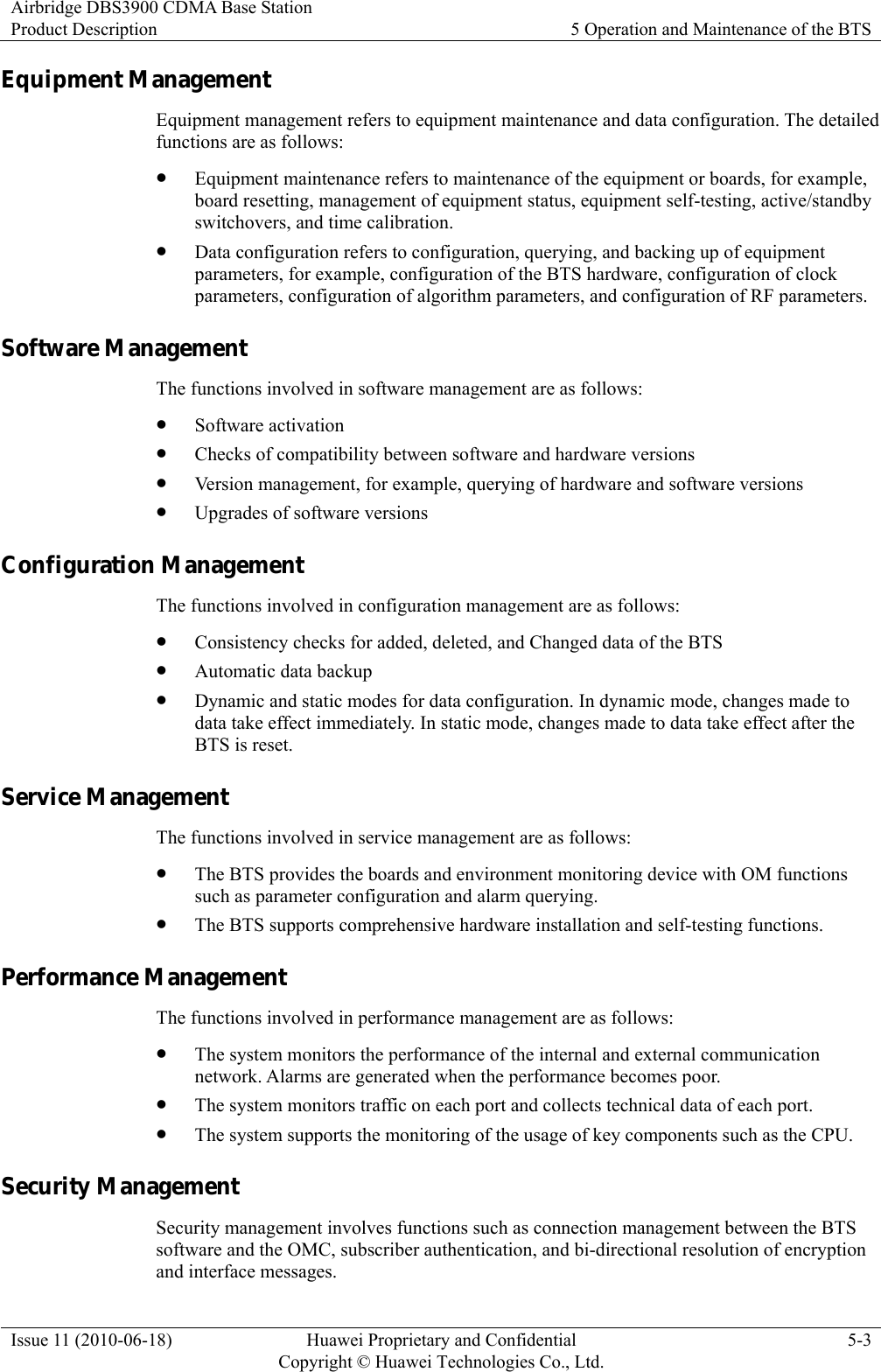
![2 Solutions for the Auxiliary Devices of the DBS3900 Airbridge DBS3900 CDMA Base StationProduct Description 2-8 Huawei Proprietary and Confidential Copyright © Huawei Technologies Co., Ltd.Issue 11 (2010-06-18) z If the distance between the RRU3606 and the BBU3900 exceeds 70 m [229.66 ft], independent power supply equipment needs to be configured for the RRU3606. z The auxiliary devices should be configured according to the actual situation and power input mode.](https://usermanual.wiki/Huawei-Technologies/RRU3606-AWS-CL/User-Guide-1308550-Page-35.png)
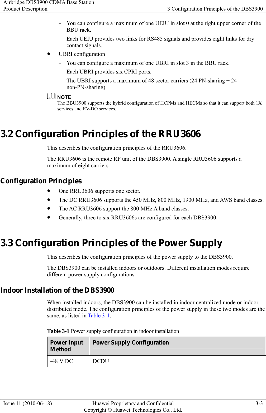
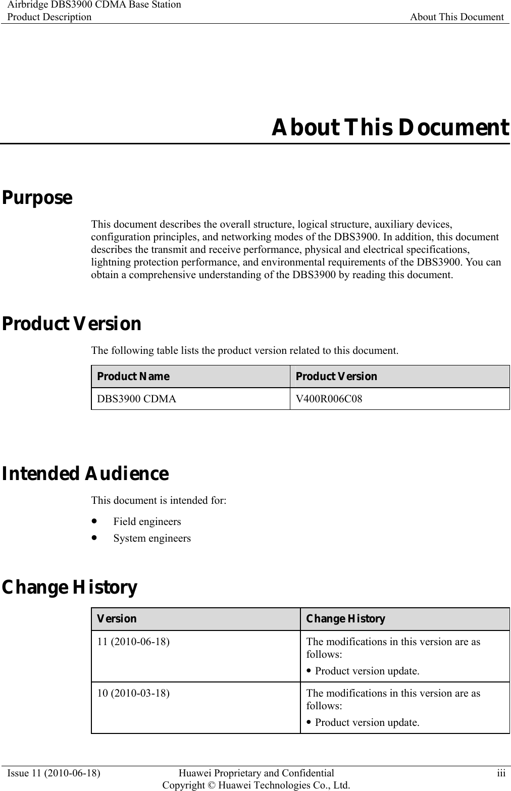
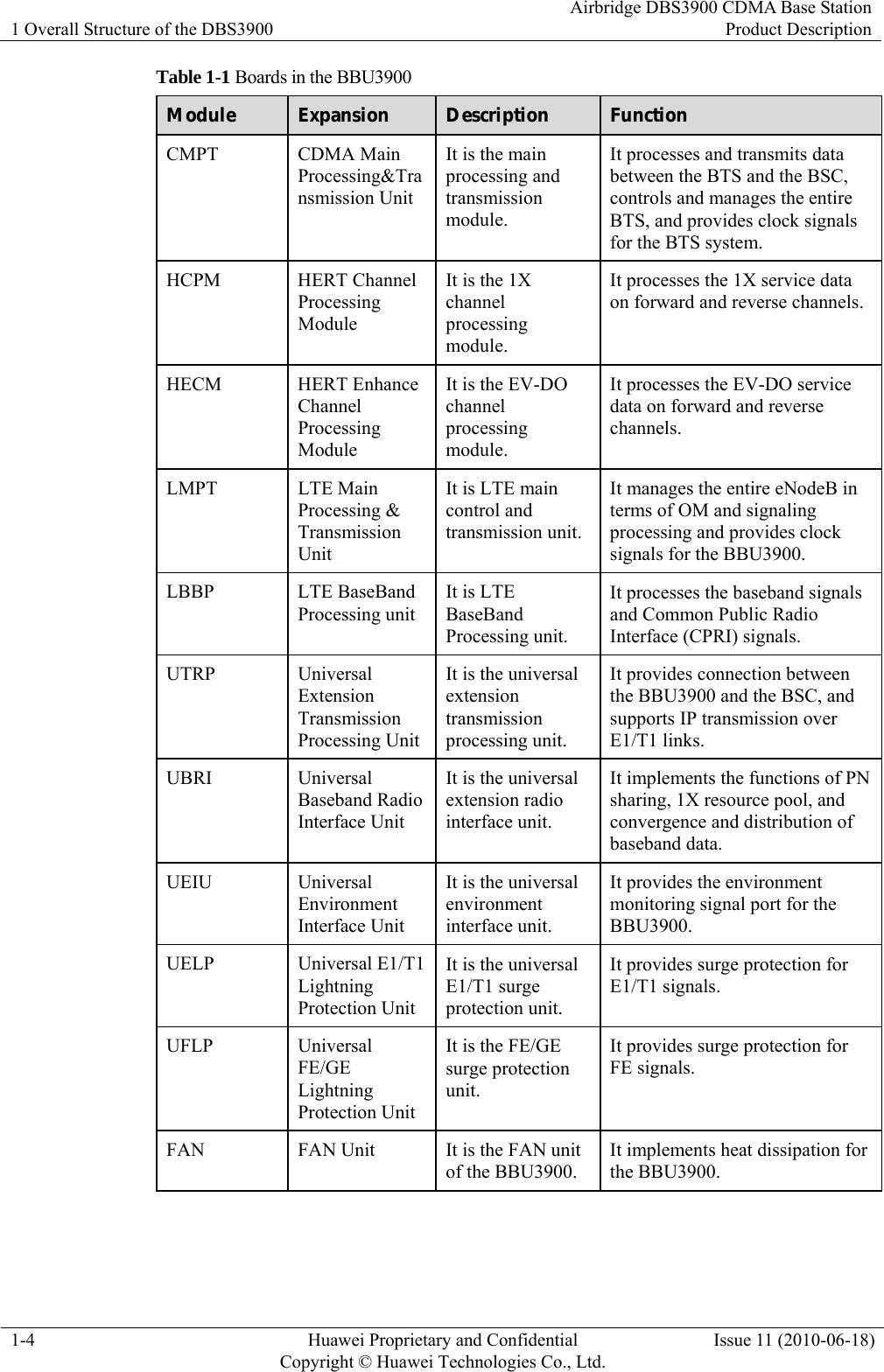
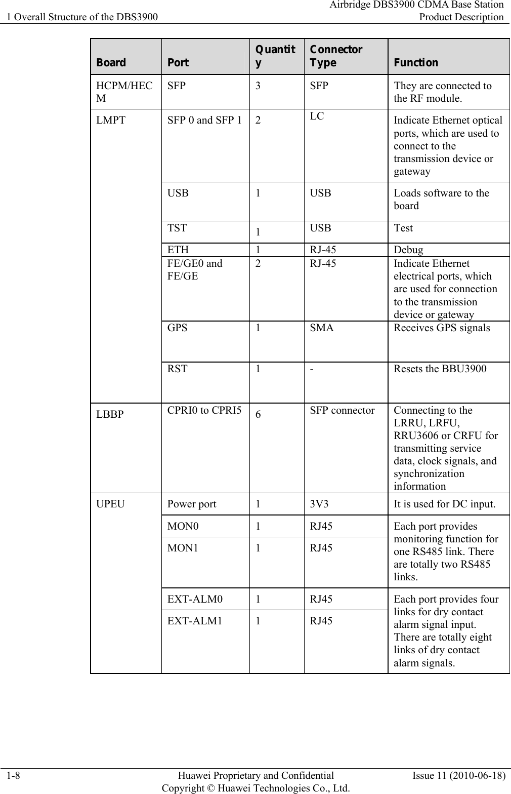
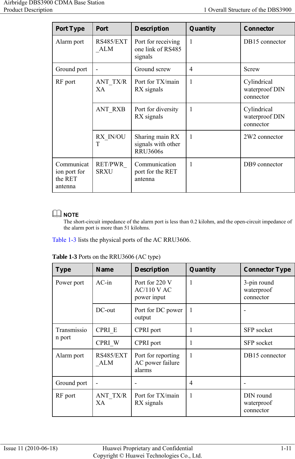
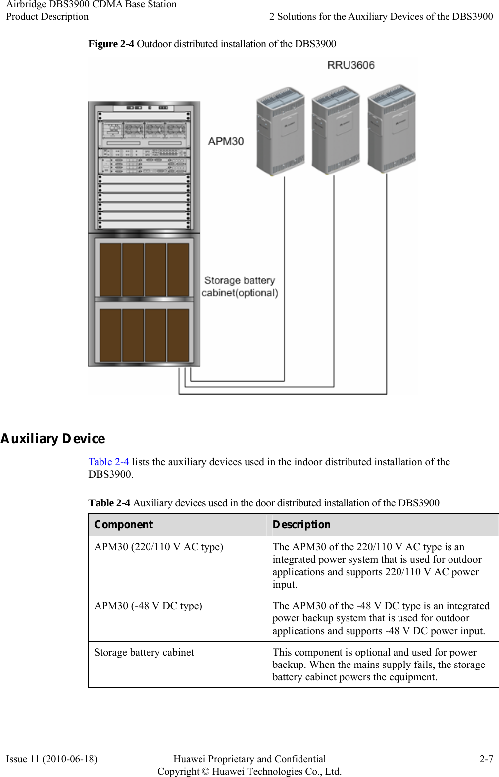
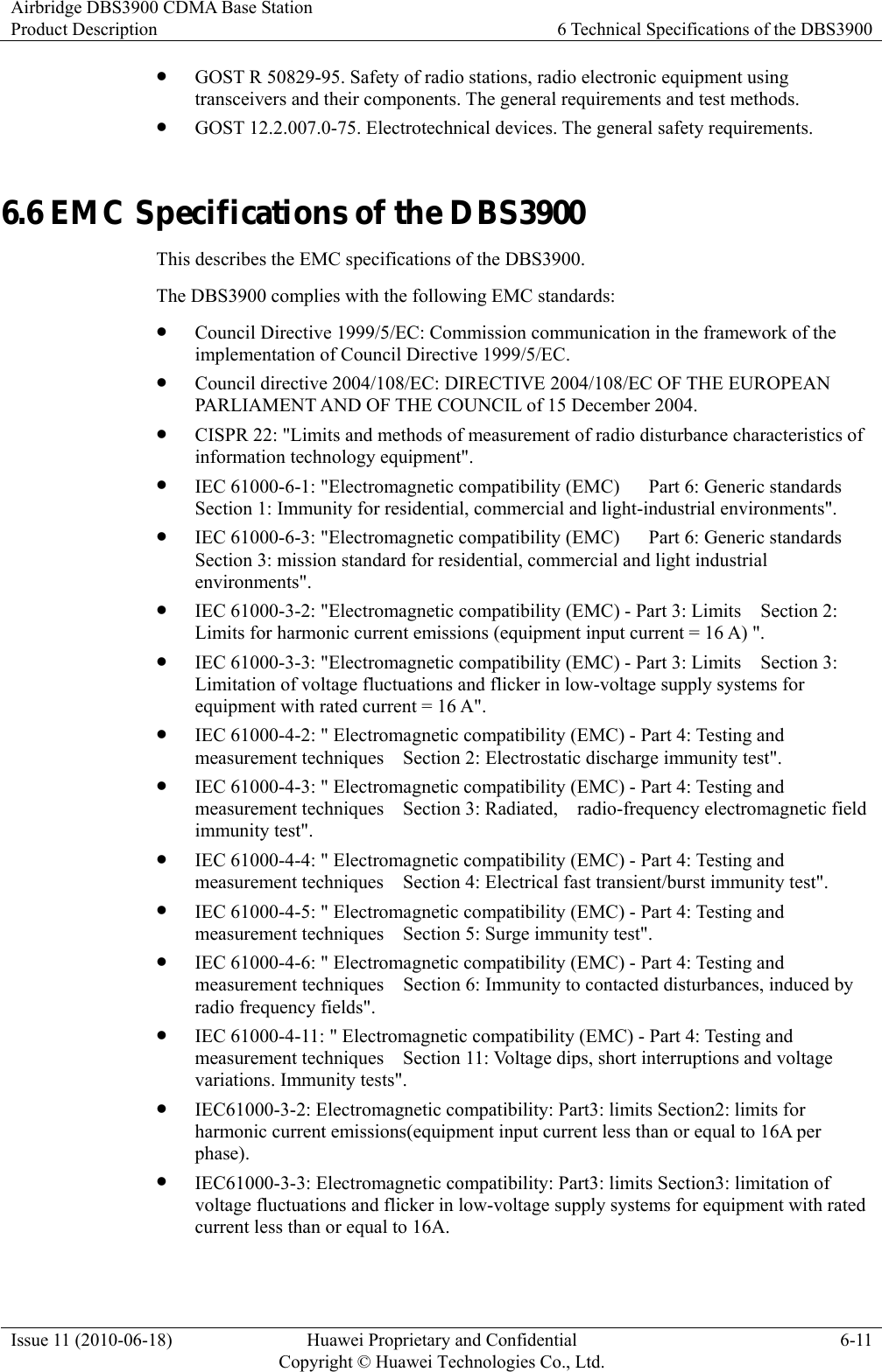
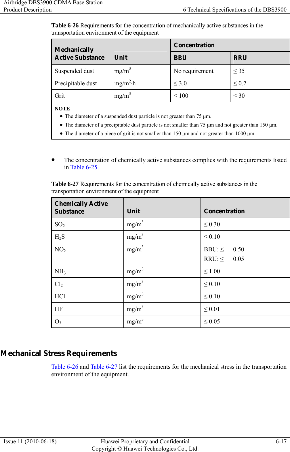
![Airbridge DBS3900 CDMA Base Station Product Description 6 Technical Specifications of the DBS3900 Issue 11 (2010-06-18) Huawei Proprietary and Confidential Copyright © Huawei Technologies Co., Ltd.6-5 Table 6-10 Receive specifications in band class 15 (AWS) of CDMA Item Specification Operating band class 1710 MHz to 1755 MHz Channel bandwidth 1.2288 MHz Channel precision 50 kHz Signal receiving sensitivity Better than -127 dBm (main and diversity receiving at RC3) Table 6-11 and Table 6-12 list the performance specifications in band class 15 (AWS) of LTE Table 6-11 Transmit specifications in band class 15 (AWS) of LTE Item Specification Operating band class 2110 MHz to 2155 MHz Channel bandwidth 5 MHz Channel precision 100 kHz Frequency tolerance ≤ ± 0.05 ppm Transmit power ≤ 60 W Table 6-12 Receive specifications in band class 15 (AWS) of LTE Item Specification Operating band class 1710 MHz to 1755 MHz Channel bandwidth 5 MHz Channel precision 100 kHz Signal receiving sensitivity Better than -104 dBm RRU3606 Cascading Specifications Table 6-11 lists the RRU3606 cascading specifications of the DBS3900. Table 6-13 RRU3606 cascading specifications of the DBS3900 Item Specification Maximum distance of single-level cascading 70 km [43.50 mi]](https://usermanual.wiki/Huawei-Technologies/RRU3606-AWS-CL/User-Guide-1308550-Page-53.png)
![6 Technical Specifications of the DBS3900 Airbridge DBS3900 CDMA Base StationProduct Description 6-6 Huawei Proprietary and Confidential Copyright © Huawei Technologies Co., Ltd.Issue 11 (2010-06-18) Item Specification Maximum number of cascading levels Three Maximum total cascading distance 90 km [55.93 mi] BER Threshold Specifications of BTS Transmission Links The bit error rates (BERs) of transmission links has the same impact on the UNI and IMA modes. Table 6-12 shows the BER threshold specifications of BTS transmission links. Table 6-14 BER threshold specifications of BTS transmission links Type Maximum BER Threshold CDMA2000 1X voice services 2 x 10e-5 Packet services 2 x 10e-6 Maintenance function 5 x 10e-5 6.2 Physical and Electrical Specifications of the DBS3900 This describes the physical and electrical specifications of the DBS3900. 6.2.1 Technical Specifications of the BBU3900 This section describes the technical specifications of the BBU3900 in terms of the working voltage, power consumption, weight, dimensions, and temperature and humidity in the running environment. 6.2.2 Technical Specifications of the RRU3606 This describes the technical specifications of the RRU3606 in terms of the working voltage, power consumption, weight, dimensions, and temperature and humidity in the running environment. 6.2.1 Technical Specifications of the BBU3900 This section describes the technical specifications of the BBU3900 in terms of the working voltage, power consumption, weight, dimensions, and temperature and humidity in the running environment. Table 6-13 lists the technical specifications of the BBU3900.](https://usermanual.wiki/Huawei-Technologies/RRU3606-AWS-CL/User-Guide-1308550-Page-54.png)
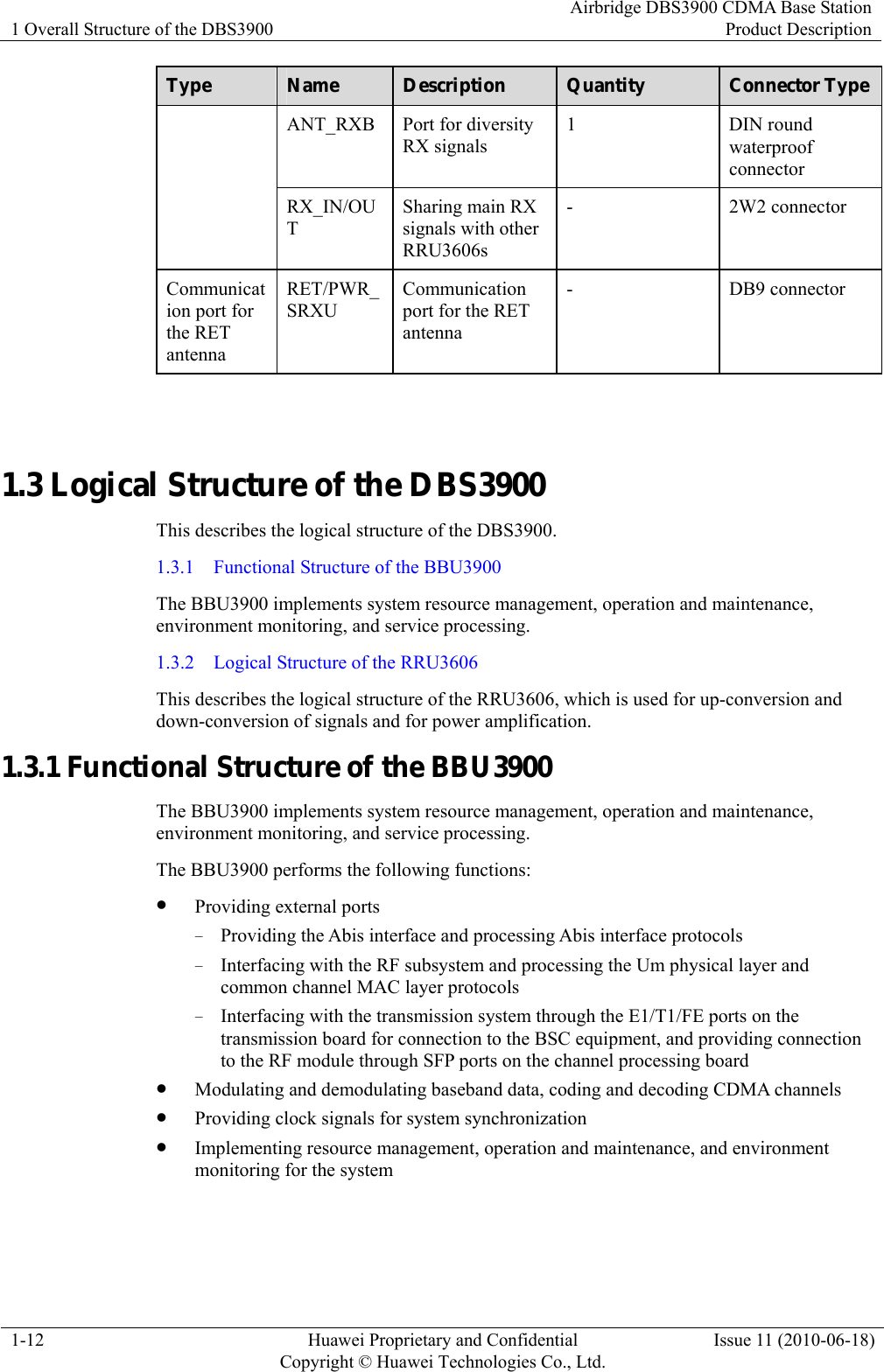
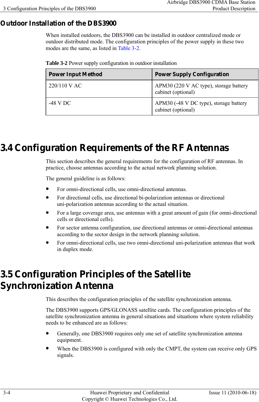
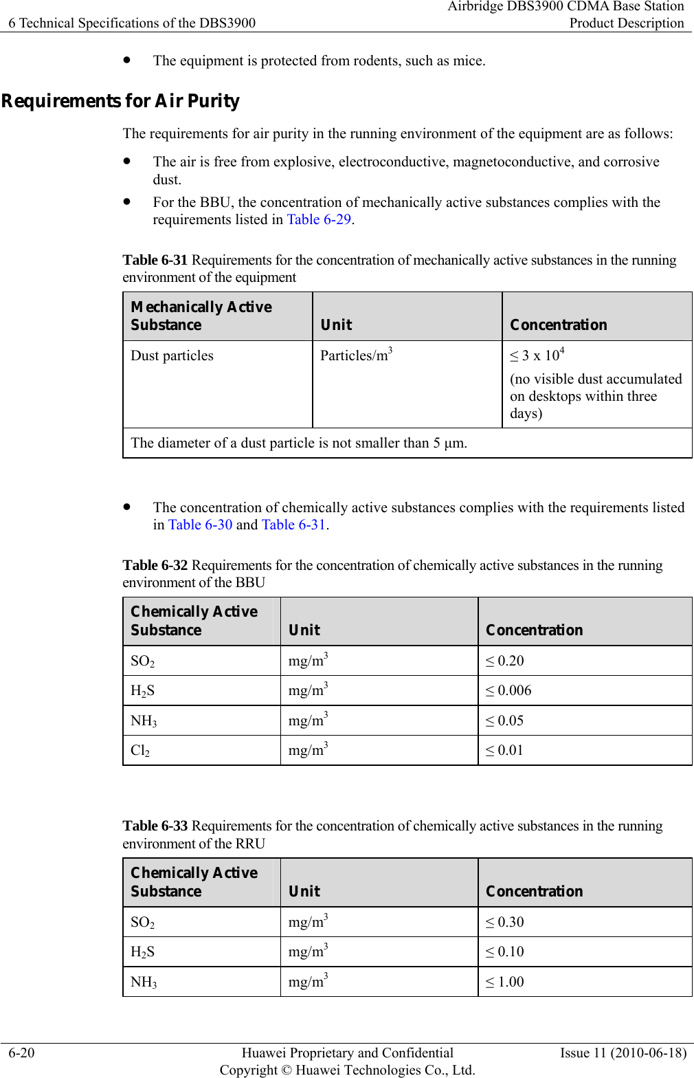
![6 Technical Specifications of the DBS3900 Airbridge DBS3900 CDMA Base StationProduct Description 6-8 Huawei Proprietary and Confidential Copyright © Huawei Technologies Co., Ltd.Issue 11 (2010-06-18) Item Specification Power consumption ≤ 295 W NOTE The power consumption is measured when the RRU3606 works at the 800 MHz band. ≤ 272 W NOTE The power consumption is measured when the RRU3606 works at the AWS band. Weight z Weights of the RRU that works in the 800 MHz AB and 450 MHz band classes: ≤ 19 kg (41.90 lb) (module + shell) z Weights of the RRU that works in other band classes: ≤ 17 kg (37.49 lb) (with the shell) Cabinet dimensions (height x width x depth) Dimensions of the RRU that works in the 800 MHz AB and 450 MHz band classes: z 485 mm (19.09 in.) x 285 mm (11.22 in.) x 170 mm (6.69 in.) (with the shell) z 480 mm (18.90 in.) x 270 mm (10.63 in.) x 140 mm (5.51 in.) (without the shell) Dimensions of the RRU that works in other band classes: z 485 mm (19.09 in.) x 285 mm (11.22 in.) x 170 mm (6.69 in.) (with the shell) z 480 mm (18.90 in.) x 270 mm (10.63 in.) x 140 mm (5.51 in.) (without the shell) Ambient temperature for operation -40oC (-40oF) to +52oC (125.6oF) (solar radiation not considered) Relative humidity for operation 5% RH to 100% RH Table 6-15 lists the technical specifications of the AC RRU3606. Table 6-17 Technical specifications of the RRU3606 (AC type) Item Specification Voltage single-phase 220 V AC (90 V AC to 290 V AC) single-phase 110 V AC (90 V AC to 290 V AC) Power consumption 333 W Weight ≤ 22.5 kg [49.6 lb] (with a shell) Cabinet dimensions (height x width x depth) 485 mm [19.21 in.] x 285 mm [11.02 in.] x 250 mm [9.84 in.] (with a shell)](https://usermanual.wiki/Huawei-Technologies/RRU3606-AWS-CL/User-Guide-1308550-Page-56.png)
![Airbridge DBS3900 CDMA Base Station Product Description 6 Technical Specifications of the DBS3900 Issue 11 (2010-06-18) Huawei Proprietary and Confidential Copyright © Huawei Technologies Co., Ltd.6-9 Item Specification Ambient temperature for running -40°C [-40°F] to +52°C [125.6°F] (solar radiation not considered) Relative humidity for running 5% RH to 100% RH 6.3 Reliability Specifications of the DBS3900 This describes the reliability specifications of the DBS3900. Table 6-16 lists the reliability specifications of the DBS3900. Table 6-18 Reliability specifications of the DBS3900 Item Specification Availability ≥ 99.999% Mean Time Between Failures (MTBF) BBU3900: ≥ 280000 hours RRU3606: ≥ 260000 hours Mean Time To Repair (MTTR) ≤ 1 hour (excluding the time needed for the engineers to arrive at the site) ≤ 3 hours (including the time needed for the engineers to arrive at the site) 6.4 Lightning Protection Specifications of the DBS3900 This describes the lightning protection specifications of the DBS3900 in terms of lightning specifications of the power input port, E1/T1 input port, GPS RF signal input port, dry contact port, and RF antenna port. Table 6-17 lists the lightning protection specifications of the DBS3900. Table 6-19 Lightning protection specifications of the DBS3900 Item Specification AC power input port Differential mode: ±60 kA, 8/20 us Common mode: ±60 kA, 8/20 us DC power input port Differential mode: ±2kA, 1.2/50 us Common mode: ±4kA, 1.2/50 us](https://usermanual.wiki/Huawei-Technologies/RRU3606-AWS-CL/User-Guide-1308550-Page-57.png)
![Airbridge DBS3900 CDMA Base Station Product Description 6 Technical Specifications of the DBS3900 Issue 11 (2010-06-18) Huawei Proprietary and Confidential Copyright © Huawei Technologies Co., Ltd.6-13 Climatic Requirements Table 6-18 lists the climatic requirements for the storage environment of the equipment. Table 6-20 Climatic requirements for the storage environment of the equipment Item Range Temperature -40oC [-40oF] to +70oC [+158oF] Temperature change rate ≤ 1oC/min Relative humidity BBU: 5%RH to 95%RH RRU: 5%RH to 100%RH Air pressure 70 kPa to 106 kPa Solar radiation ≤ 1120 W/m2 Thermal radiation ≤ 600 W/m2 Wind speed BBU: ≤ 30 m/s RRU: ≤ 50 m/s Waterproofing Requirements The waterproofing requirements for the storage environment of the equipment are as follows: z If possible, store the equipment indoors and ensure that: − No water accumulates on the ground or may drop onto the package of the equipment. − The equipment is kept away from devices that may leak water, for example, automatic fire-fighting devices and heating devices. z If the equipment has to be stored outdoors, ensure that: − The package is intact. − Appropriate waterproofing measures are taken to prevent rainwater from entering the package. − No water accumulates on the ground or may drop onto the package of the equipment. − The package is not exposed directly to sunlight. Biological Requirements The biological requirements for the storage environment of the equipment are as follows: z The environment is not conducive to the growth of microorganisms, such as fungi. z The equipment is protected from rodents, such as mice. Air Purity Requirements The air purity requirements for the storage environment of the equipment are as follows: z The air is free from explosive, electroconductive, magnetoconductive, and corrosive dust.](https://usermanual.wiki/Huawei-Technologies/RRU3606-AWS-CL/User-Guide-1308550-Page-61.png)
![Airbridge DBS3900 CDMA Base Station Product Description 6 Technical Specifications of the DBS3900 Issue 11 (2010-06-18) Huawei Proprietary and Confidential Copyright © Huawei Technologies Co., Ltd.6-15 Table 6-23 Requirements for the mechanical stress in the storage environment of the BBU Item Sub-item Range Offset ≤ 7.0 mm [0.28 in.] - Acceleration - ≤ 20 m/s2 Sinusoidal vibration Frequency range 2 Hz to 9 Hz 9 Hz to 200 Hz Impact response spectrum II ≤ 250 m/s2 Unsteady impact Static payload ≤ 5 kPa NOTE z The impact response spectrum refers to the maximum acceleration response curve generated by the equipment under specified impact excitation. Impact response spectrum II means that the duration of semi-sine impact response spectrum is 6 ms. z The static payload refers to the capability of the packed equipment to bear the weight from above in the stipulated stack method. Table 6-24 Requirements for the mechanical stress in the storage environment of the RRU Item Sub-item Range Offset ≤ 1.5 mm [0.06 in.] - Acceleration - ≤ 5 m/s2 Sinusoidal vibration Frequency range 2 Hz to 9 Hz 9 Hz to 200 Hz Impact response spectrum II ≤ 250 m/s2 Unsteady impact Static payload ≤ 5 kPa NOTE z The impact response spectrum refers to the maximum acceleration response curve generated by the equipment under specified impact excitation. Impact response spectrum II means that the duration of semi-sine impact response spectrum is 6 ms. z The static payload refers to the capability of the packed equipment to bear the weight from above in the stipulated stack method. 6.7.2 Transportation Environment This describes the requirements for the transportation environment of the DBS3900. Climatic Requirements Table 6-23 lists the climatic requirements for the transportation environment of the equipment.](https://usermanual.wiki/Huawei-Technologies/RRU3606-AWS-CL/User-Guide-1308550-Page-63.png)
![6 Technical Specifications of the DBS3900 Airbridge DBS3900 CDMA Base StationProduct Description 6-16 Huawei Proprietary and Confidential Copyright © Huawei Technologies Co., Ltd.Issue 11 (2010-06-18) Table 6-25 Climatic requirements for the transportation environment of the equipment Item Range Temperature -40oC [-40oF] to +70oC [+158oF] Temperature change rate ≤ 3oC/min Relative humidity 5% RH to 95% RH Air pressure 70 kPa to 106 kPa Solar radiation ≤ 1120 W/m2 Thermal radiation ≤ 600 W/m2 Wind speed BBU: ≤ 30 m/s RRU: ≤ 50 m/s Waterproofing Requirements The waterproofing requirements for the transportation environment of the equipment are as follows: z The package is intact. z Appropriate waterproofing measures are taken to prevent rainwater from entering the package. z No water accumulates in the vehicle. Biological Requirements The biological requirements for the transportation environment of the equipment are as follows: z The environment is not conducive to the growth of microorganisms, such as fungi. z The equipment is protected from rodents, such as mice. Air Purity Requirements The requirements for the air purity in the transportation environment of the equipment are as follows: z The air is free from explosive, electroconductive, magnetoconductive, and corrosive dust. z The concentration of mechanically active substances complies with the requirements listed in Table 6-24.](https://usermanual.wiki/Huawei-Technologies/RRU3606-AWS-CL/User-Guide-1308550-Page-64.png)
![6 Technical Specifications of the DBS3900 Airbridge DBS3900 CDMA Base StationProduct Description 6-18 Huawei Proprietary and Confidential Copyright © Huawei Technologies Co., Ltd.Issue 11 (2010-06-18) Table 6-28 Requirements for the mechanical stress in the transportation environment of the BBU Item Sub-item Range Offset ≤ 7.5 mm [0.30 in.] - - Acceleration - ≤ 20.0 m/s2 ≤ 40. 0 m/s2 Sinusoidal vibration Frequency range 2 Hz to 9 Hz 9 Hz to 200 Hz 200 Hz to 500 Hz Acceleration spectral density10 m2/s3 3 m2/s3 1 m2/s3 Random vibration Frequency range 2 Hz to 9 Hz 9 Hz to 200 Hz 200 Hz to 500 Hz Impact response spectrum II ≤ 300 m/s2 Unsteady impact Static payload ≤ 10 kPa NOTE z The impact response spectrum refers to the maximum acceleration response curve generated by the equipment under specified impact excitation. Impact response spectrum II means that the duration of semi-sine impact response spectrum is 6 ms. z The static payload refers to the capability of the packed equipment to bear the weight from above in the stipulated stack method. Table 6-29 Requirements for the mechanical stress in the transportation environment of the RRU Item Sub-item Range Offset ≤ 3.5 mm [0.14 in.] - - Acceleration - ≤ 10 m/s2 ≤ 15 m/s2 Sinusoidal vibration Frequency range 2 Hz to 9 Hz 9 Hz to 200 Hz 200 Hz to 500 Hz Acceleration spectral density30 m2/s3 3 m2/s3 1 m2/s3 Random vibration Frequency range 2 Hz to 10 Hz 10 Hz to 200 Hz 200 Hz to 500 Hz Impact response spectrum II ≤ 250 m/s2 Unsteady impact Static payload ≤ 10 kPa](https://usermanual.wiki/Huawei-Technologies/RRU3606-AWS-CL/User-Guide-1308550-Page-66.png)
![Airbridge DBS3900 CDMA Base Station Product Description 6 Technical Specifications of the DBS3900 Issue 11 (2010-06-18) Huawei Proprietary and Confidential Copyright © Huawei Technologies Co., Ltd.6-19 Item Sub-item Range NOTE z The impact response spectrum refers to the maximum acceleration response curve generated by the equipment under specified impact excitation. Impact response spectrum II means that the duration of semi-sine impact response spectrum is 6 ms. z The static payload refers to the capability of the packed equipment to bear the weight from above in the stipulated stack method. 6.7.3 Requirements for the Running Environment of the DBS3900 This describes the requirements for the running environment of the equipment in terms of climatic requirements, waterproofing requirements, biological requirements, and requirements for air purity and mechanical stress. Climatic Requirements Table 6-28 lists the climatic requirements for the running environment of the equipment. Table 6-30 Climatic requirements for the running environment of the equipment Item Range Temperature BBU: -10°C [+14°F] to +55°C [+131°F] RRU: -40°C [-40°F] to +52°C [+125.6°F] (solar radiation not considered) Temperature change rate ≤ 3oC/min Relative humidity BBU: 5% RH to 95% RH RRU: 5% RH to 100% RH Air pressure 70 kPa to 106 kPa Solar radiation BBU: ≤ 700 W/m2 RRU: ≤ 1120 W/m2 Thermal radiation ≤ 600 W/m2 Wind speed BBU: ≤ 1 m/s RRU: ≤ 67 m/s NOTE The temperature and humidity should be measured 1.5 m [4.92 ft] above the ground and 0.4 m [1.31 ft] away from the front of the cabinet when no protective board is installed at the front and rear of the cabinet. Biological Requirements The biological requirements for the running environment of the equipment are as follows: z The environment is not conducive to the growth of fungus.](https://usermanual.wiki/Huawei-Technologies/RRU3606-AWS-CL/User-Guide-1308550-Page-67.png)
![Airbridge DBS3900 CDMA Base Station Product Description 6 Technical Specifications of the DBS3900 Issue 11 (2010-06-18) Huawei Proprietary and Confidential Copyright © Huawei Technologies Co., Ltd.6-21 Chemically Active Substance Unit Concentration Cl2 mg/m3 ≤ 0.10 HCl mg/m3 ≤ 0.10 HF mg/m3 ≤ 0.01 O3 mg/m3 ≤ 0.05 NOX mg/m3 ≤ 0.05 Requirements for Mechanical Stress Table 6-32 and Table 6-33 list the requirements for the mechanical stress in the running environment of the equipment. Table 6-34 Requirements for the mechanical stress in the running environment of the BBU Item Sub-Item Range Offset ≤ 3.5 mm [0.14 in.] - Acceleration - ≤ 10.0 m/s2 Sinusoidal vibration Frequency range 2 Hz to 9 Hz 9 Hz to 200 Hz Impact response spectrum II ≤ 100 m/s2 Unsteady impact Static payload 0 NOTE z The impact response spectrum refers to the maximum acceleration response curve generated by the equipment under specified impact excitation. Impact response spectrum II means that the duration of semi-sine impact response spectrum is 6 ms. z The static payload refers to the capability of the packed equipment to bear the weight from above in the stipulated stack method. Table 6-35 Requirements for the mechanical stress in the running environment of the RRU Item Sub-Item Range Offset ≤ 3 mm [0.12 in.] - Acceleration - ≤ 10.0 m/s2 Sinusoidal vibration Frequency range 2 Hz to 9 Hz 9 Hz to 200 Hz Impact response spectrum II ≤ 250 m/s2 Unsteady impact Static payload 0](https://usermanual.wiki/Huawei-Technologies/RRU3606-AWS-CL/User-Guide-1308550-Page-69.png)