Huawei Technologies RRU3702-2500 Remote Radio Unit User Manual Installation Guide
Huawei Technologies Co.,Ltd Remote Radio Unit Installation Guide
UserManual.wiki
>
Huawei Technologies
>
RRU3702-2500 User Manual
>
Installation Guide
Contents
1.
Installation Manual
2.
Installation Guide
Installation Guide
Navigation menu
Upload a User Manual
Namespaces
Wiki Guide
HTML
PDF
Info
Views
User Manual
Discussion / Help
Navigation
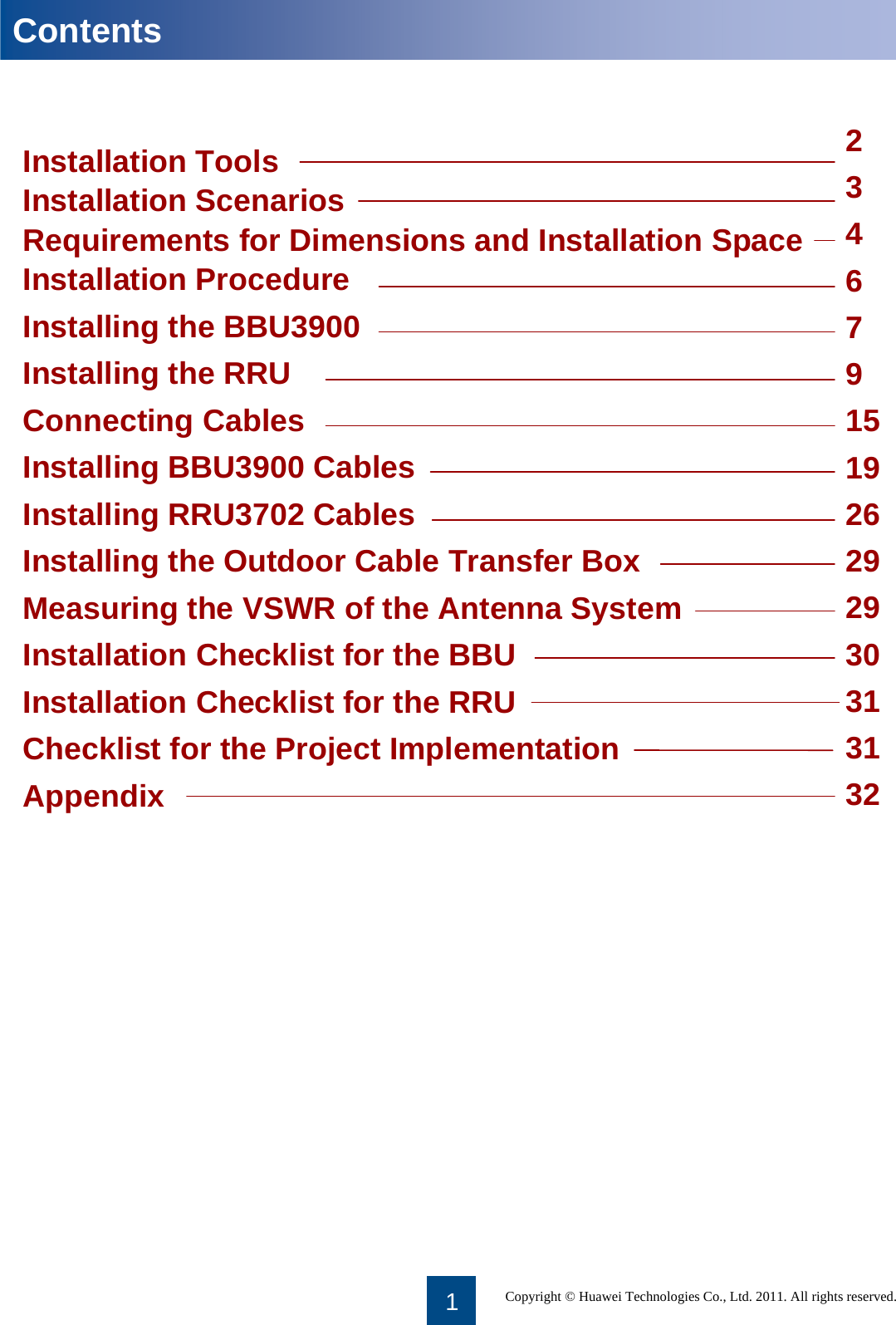
![2Installation ToolsMultimeterUtility knifeHammer drill (with bit 14) Vacuum cleanerESD glovesHeat gunFlat-head screwdriver(M3 to M6)Wire stripperWire cutterAdjustable wrench[with a diameter of at least 32 mm (1 1/4")]Torque screwdriverMeasuring tapeLevelMarking pen[with a diameter of no more than 10 mm (0 3/8")]Combination wrenchPhillips screwdriver(M3 to M6)Torque wrenchCrimping pliersRubber mallet[21 mm (0 13/16") to 21 mm (0 13/16")] for pole installation[17 mm (0 11/16") to 17 (0 11/16")]for wall installation](https://usermanual.wiki/Huawei-Technologies/RRU3702-2500.Installation-Guide/User-Guide-1589721-Page-3.png)
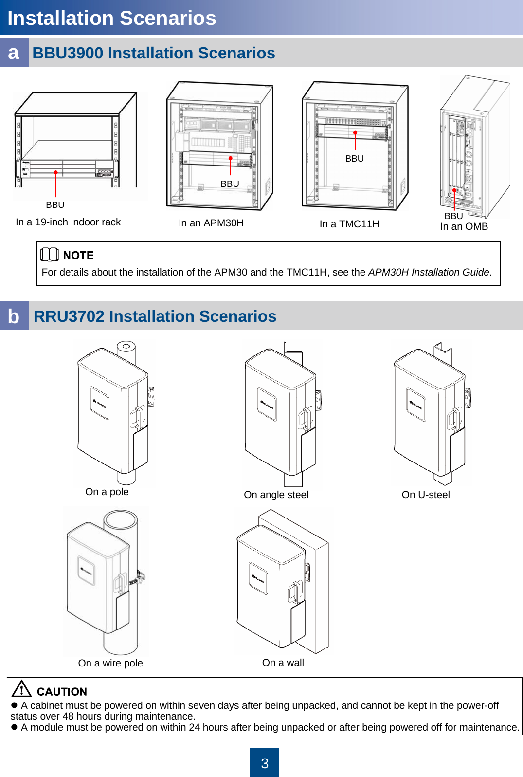
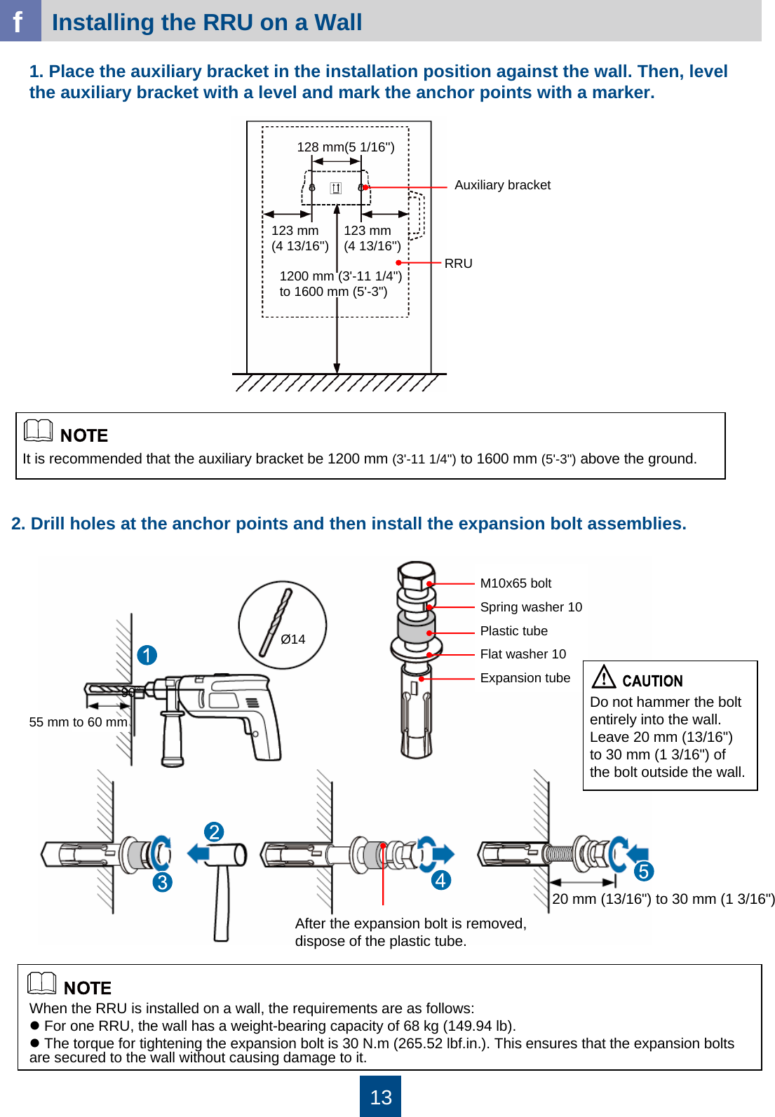
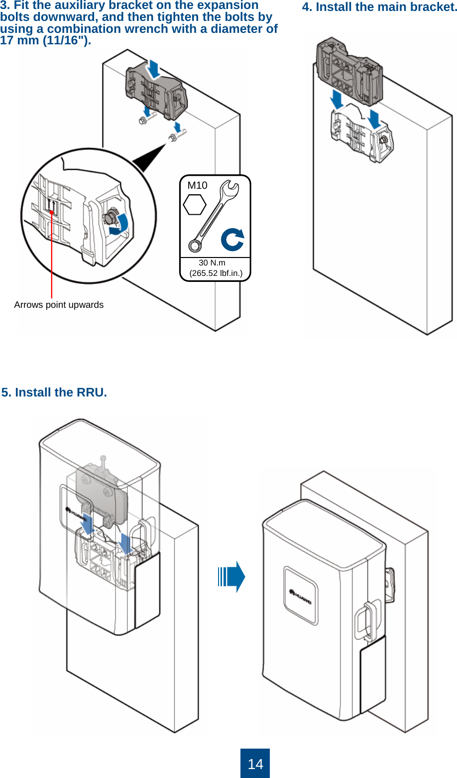
![9Tighten the screws when installing the RRU. Loosen these screws when removing the RRU.Installing the RRUaInstalling the RRU on a Pole [Diameter: 60 mm (2 3/8'') to 114 mm (4 1/2'')]zThe RRU must be supported by foam or cardboard for protection.zThe RF ports at the bottom of the RRU cannot bear the weight of the RRU. Do not place the RRU on the ground in the upright position.Dual-nut boltMain bracketAuxiliary bracket1200 mm (3'-11 1/4'') to 1600 mm (5'-3'')When installing the main bracket, ensure that the contact piece on the bracket is fixed.You may fit one end of the auxiliary bracket on one dual-nut bolt assembly and then the other end on the other dual-nut bolt assembly during the installation.1. Install the main bracket.60 mm (2 3/8'') to 114 mm (4 1/2'')The recommended diameter of the pole is 80 mm (3 1/8").Mounting brackets for RRUFixing hoopLogo on the cover plate Transfer pieces Tighten the screws when removing the RRU.Main bracketSpring plate≤10°RRUAngle steel or U-steelThe angle between the vertical and the angle steel or U-steel or angle steel where the RRU is installed must be less than or equal to 10 degree.](https://usermanual.wiki/Huawei-Technologies/RRU3702-2500.Installation-Guide/User-Guide-1589721-Page-10.png)
![10Installing Two RRUs on a Pole[Diameter: 60 mm (2 3/8'') to 114 mm (4 1/2'')]bTighten the two dual-nut bolt assemblies alternatively. After the brackets are secured, use a measuring tape to measure the spacing between the main bracket and the auxiliary bracket on two sides and confirm that the spacing is the same.2. Use an adjustable wrench to tighten the nut until the fastening torque is 40 N.m(354.03 lbf.in.). This secures the main and auxiliary brackets to the pole.3. Install the RRU on the main bracket. When you hear click sound, the RRU is securely installed.The arrows on the main bracket point upwards.1. Install the first RRU. 2. Install the second main bracket.40 N.m(354.03 lbf.in.)](https://usermanual.wiki/Huawei-Technologies/RRU3702-2500.Installation-Guide/User-Guide-1589721-Page-11.png)
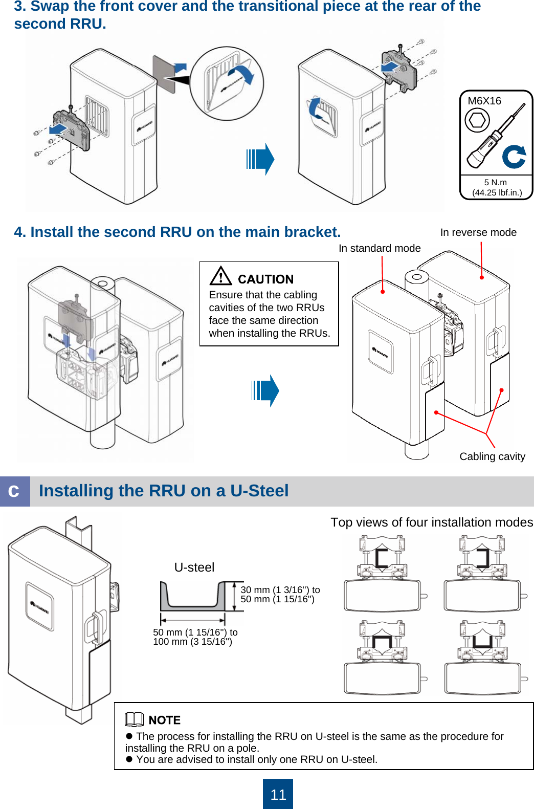
![12Top views of the installation modesdInstalling the RRU on Angle SteelAngle steel63 mm (2 1/2'') to 80 mm (3 1/8'')63 mm (2 1/2'') to 80 mm (3 1/8'')You are advised to install only one RRU on a wire pole.eInstalling the RRU on a Wire Pole [Diameter: 300 mm (11 4/5'') to 390 mm (1' 3 3/8'')]zThe process for installing the RRU on angle steel is the same as the procedure for installing the RRU on a pole.zYou are advised to install only one RRU on angle steel.Main bracket35N•m(309.78 lbf.in.)](https://usermanual.wiki/Huawei-Technologies/RRU3702-2500.Installation-Guide/User-Guide-1589721-Page-13.png)
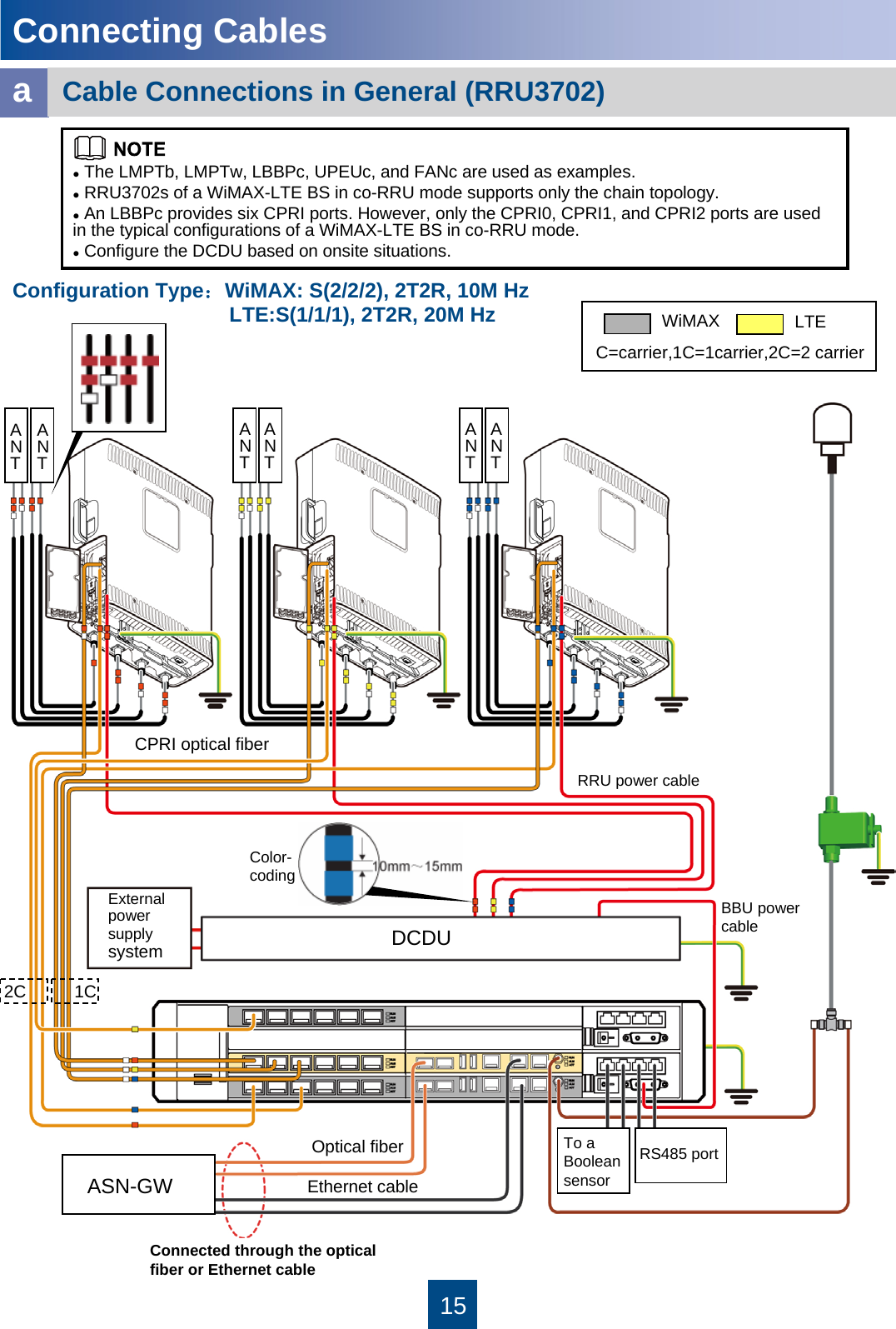
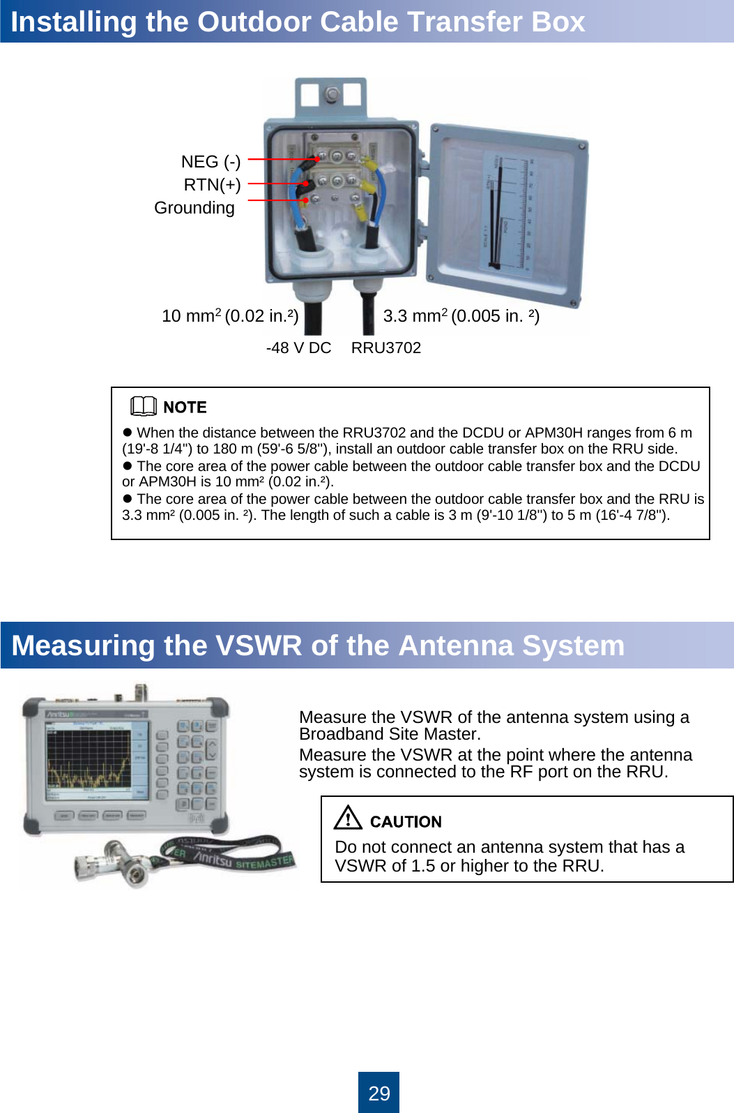
![28dInstalling the RF Jumper of the RRU3702 Connections between the 4T4R RRU and the 4-port antennaIdentify the RF ports. The names of the RF ports are silk screened above the port. Connect the jumpers based on the connection relationship shown in the figure above.Wrap a layer of insulation tapeWrap three layers of waterproof tapeWrap three layers of insulation tapeSecure the connector to the port using a wrench [torque: 1 N.m (8.85 lbf.in.)]. Wrap the connector with insulation tape and with waterproof tape.Before installing the RF jumper, measure the VSWR of the antennasystem. For details, see "Measuring the VSWR of the Antenna System" on page 29.Installing the RF jumperTake insulation and waterproof measures only for the RF jumpers connected to outdoor RRUs.ANTENNARRURF jumperWaterproof tapeDustproof capPVC insulation tapeKeep the dustproof caps on vacant feeder connectors. Wrap the feeder connectors with waterproof tape for outdoor scenarios, as shown in the following figure.PVC insulation tapeANTA_TX/RX ANTB_TX/RX ANTC_TX/RX ANTD_TX/RX](https://usermanual.wiki/Huawei-Technologies/RRU3702-2500.Installation-Guide/User-Guide-1589721-Page-29.png)