Huawei Technologies RRU3808 Distributed Base Station Remote Radio Unit User Manual Installation Guide
Huawei Technologies Co.,Ltd Distributed Base Station Remote Radio Unit Installation Guide
Installation Guide

HUAWEI TECHNOLOGIES Co., Ltd.
Issue: 04
Date:2010-03-05
RRU3808 V200
Installation Guide

1
Safety Information …………………………………………….….……
Installation Tools ………………………………………….…………..
Space Requirements …………………………………….……..…….
Installation Modes …………………………………………………….
Installation Procedure …………………………………….………….
Components Delivered with the RRU ……………………………..
Installing the RRU on a Metal Pole ………………..……………….
Installing the RRU on a U-Steel ……………….……….…………..
Installing the RRU on an Angle Steel ……………………………..
Installing the RRU on a Wall ………………………………………..
Installing the RRU Cables …………………………………………..
RRU Hardware Installation Checklist ……………………………..
Powering On the RRU …………………………………...…………..
Appendix ………………………………………………………..……..
Change History …………………………………...…………………..
Contents
2
3
4
5
7
7
8
12
12
13
15
24
24
25
30
Copyright © Huawei Technologies Co., Ltd. 2010. All rights reserved.
2
Safety Information
Following All Safety Precautions
Before any operation, read the instructions and precautions in this document carefully to minimize the possibility
of accidents.
The Danger, Caution, and Note items in the documents do not cover all the safety precautions that must be
followed. They only provide the generic safety precautions for operations.
When operating Huawei products and equipment, you must comply with safety precautions and special safety
instructions related to corresponding equipment provided by Huawei. The safety precautions in the document
are related to only Huawei products. Huawei is not liable for any consequence that results from the violation of
universal regulations for safety operations and safety codes on design, production, and equipment use.
Complying with the Local Safety Regulations
When operating the device, comply with the local safety regulations. The safety precautions provided in the
documents are supplementary.
Qualified Personnel Only
The personnel in charge of installation and maintenance must be trained and master the correct operating
methods and safety precautions before beginning work.
Symbols
Safety of Personnel
• The high voltage power supply provides power for running the system. Direct contact with the high voltage
power supply or contact through damp objects may result in fatal danger.
• Non-standard and improper high voltage operations may result in fire and electric shock.
• In a thunderstorm, do not perform operations on high voltage and AC power supply facilities or on a steel
tower and mast.
• Ground the device before powering on the device. Otherwise, the personnel and device are in danger.
• Power off the device before performing operations on the power supply equipment.
• High power radio-frequency signals are harmful to human body. Before installing or maintaining an antenna
on a steel tower or mast with a large number of transmitter antennas, the operator should coordinate with all
parties to ensure that the transmitter antennas are shut down.
• When handling optical fibers, do not stand close to, or look into the optical fiber outlet with unaided eyes.
• Protect yourself when drilling holes. Flying dust may hurt your eyes or you may inhale the dust.
• Power off the batteries before connecting the cables to the batteries. Otherwise, casualties may occur.
• When working at a height, be cautious about falling objects.
Device Safety
• Check the electrical connection of the device before operation and ensure that the device is reliably grounded.
• The static electricity generated by the human body may damage the electrostatic sensitive components on
the circuit board, such as the large-scale integrated circuit (LIC). Wear an electrostatic discharge (ESD) wrist
strap or ESD gloves when performing the operation.
• When working on batteries, take measures to prevent short circuits in the batteries and electrolyte spill/loss.
The electrolyte may erode metal and boards, or even cause rust of the equipment or short circuits in the boards.
• When the equipment is unpacked, it must be powered on in 24 hours. The maximum duration of the power-
off state of the equipment is 24 hours during maintenance.
Indicates a hazard with a high level of risk, which if not avoided, will result in death or
serious injury.
DANGER
WARNING
CAUTION
TIP
NOTE
Indicates a hazard with a medium or low level of risk, which if not avoided, could result
in minor or moderate injury.
Indicates a potentially hazardous situation, which if not avoided, could result in
equipment damage, data loss, performance degradation, or unexpected results.
Indicates a tip that may help you solve a problem or save time.
Provides additional information to emphasize or supplement important points of the
main text.
3
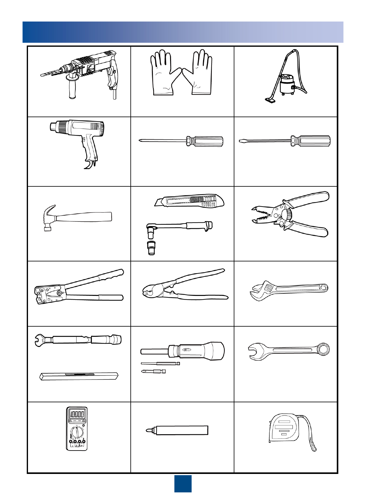
Installation Tools
Multimeter
Knife
Hammer drill (with bit 14) Vacuum cleaner
Claw hammer
ESD gloves
Heat gun
Flat-head screwdriver
(M3~M6)
Wire stripper
Wire cutter
Power cable crimping pliers
Adjustable wrench
(with the diameter of at laest 32 mm)
Torque screwdriver
Measuring tape
Level
Marking pen
(with the diameter of no more
than 10 mm)
Combination wrench
(21mm~21mm) for pole installation
(17mm~17mm) for wall installation
Phillips screwdriver
(M3~M6)
Torque wrench
Torque socket
4
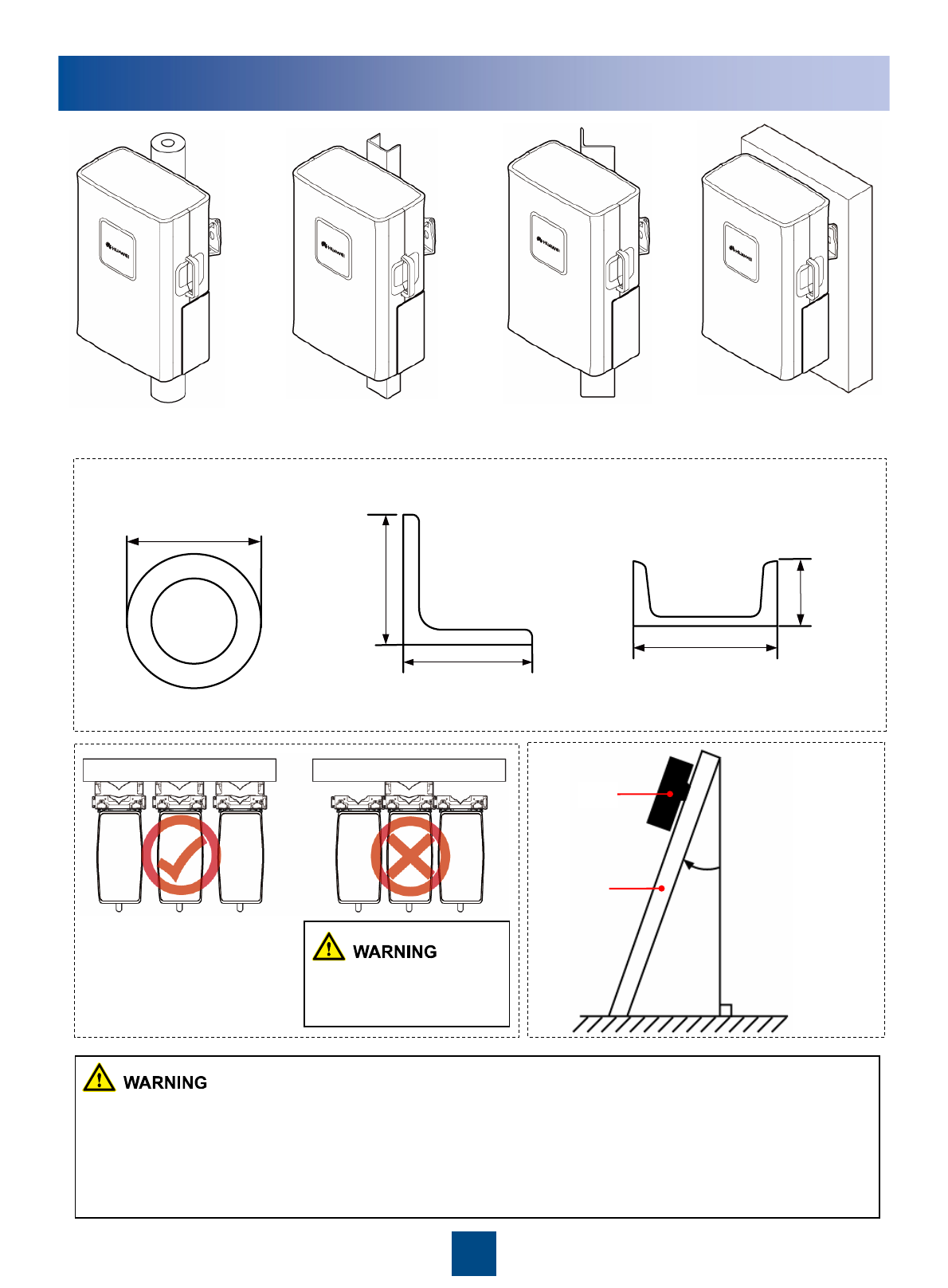
60 mm to 114 mm
63mm
~
80mm
63 mm to 75 mm
63 mm to 75 mm
50 mm to 100 mm
30 mm to 50 mm
≤10°
RRU
Angle steel
or U-steel
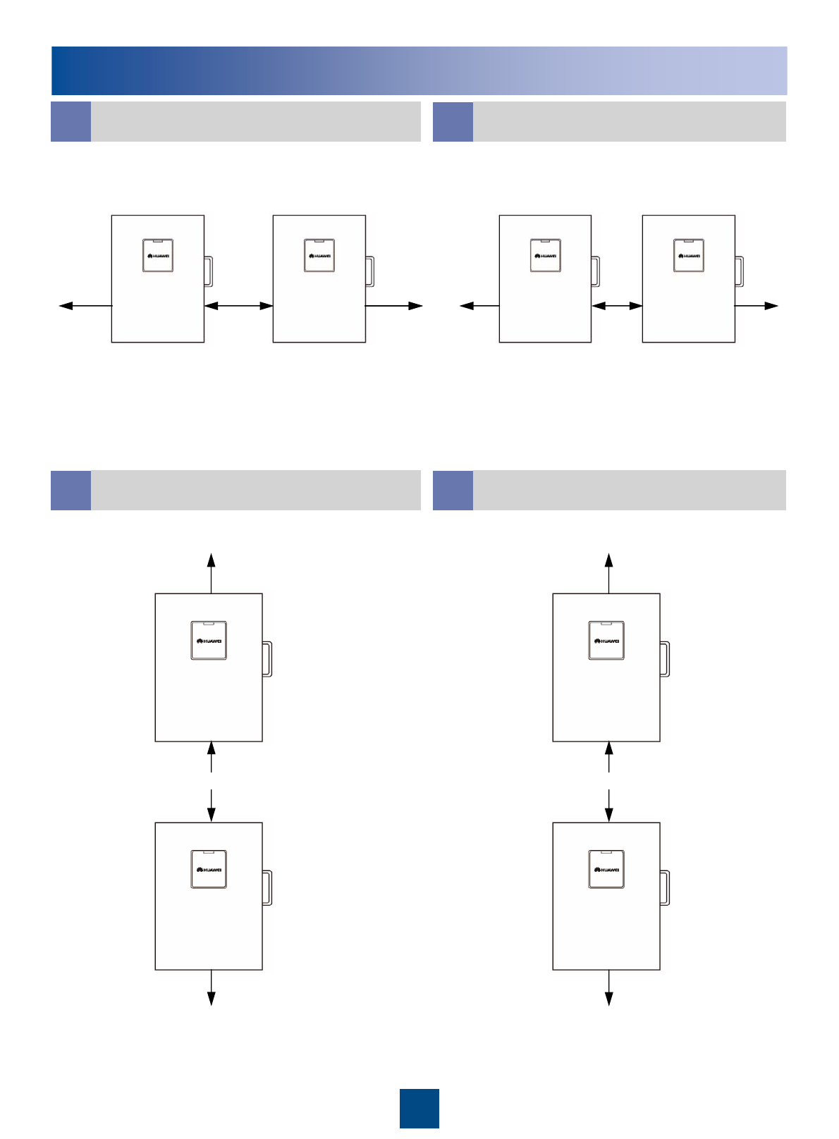
On a metal pole On a wall
On an angle steel
On a U-steel
Installation Options
The following figure describes the specifications for the metal pole, angle steel, and U-steel where the RRU is
installed.
Metal pole Angle steel U-steel
The brackets cannot be
combined when the RRUs
are installed on the wall.
zA maximum of two RRUs can be installed on a metal pole with a diameter of 60 mm to 75 mm, and the
installation mode must be standard mode. Three or more RRUs must be installed on a metal pole with a
diameter of 76 mm to 114 mm in a centralized way.
zIt is recommended that only one RRU be installed on a U-steel or an angle steel.
zWhen installed on a tower, one RRU can be installed only in standard mode or reverse mode rather than
side-mounted. Two RRUs cannot be installed in back-to-back mode.
The angle between
the vertical and the
angle steel or U-
steel or angle steel
where the RRU is
installed must be
less than or equal to
10 degree.
5
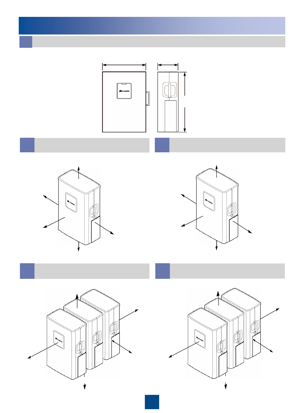
Dimensions and Installation Clearance
≥300 mm
≥500 mm
≥800 mm
≥600 mm
≥300 mm
200 mm
300 mm
600 mm
400 mm
100 mm
300 mm
200 mm
600 mm
300 mm
300 mm
a
285 mm 170 mm
485 mm
≥300 mm
≥800 mm
≥500 mm
≥500 mm
≥500 mm
Dimensions of the RRU
bRecommended Clearance for a
Single RRU
dRecommended Clearance for
Multiple Centralized RRUs eMinimum Clearance for Multiple
Centralized RRUs
cMinimum Clearance for a Single
RRU
6
≥300 mm ≥600 mm ≥600 mm 100 mm 400 mm 400 mm
≥500 mm
≥500 mm
≥300 mm
300 mm
300 mm
200 mm
Dimensions and Installation Clearance
f g
Recommended Horizontal Spacing for
Two RRUs Installed in Parallel Minimum Horizontal Spacing for Two
RRUs Installed in Parallel
hi
Recommended Vertical Spacing for
Two RRUs Installed in Parallel Minimum Vertical Spacing for Two
RRUs Installed in Parallel
7
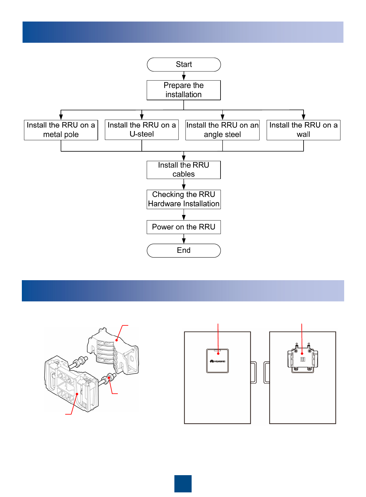
Dual-nut bolt
Main bracket
Auxiliary bracket
Cover plate Attachment plate
Installation Procedure
Preparing the Installation
Main and auxiliary brackets for the RRU Front Back
8
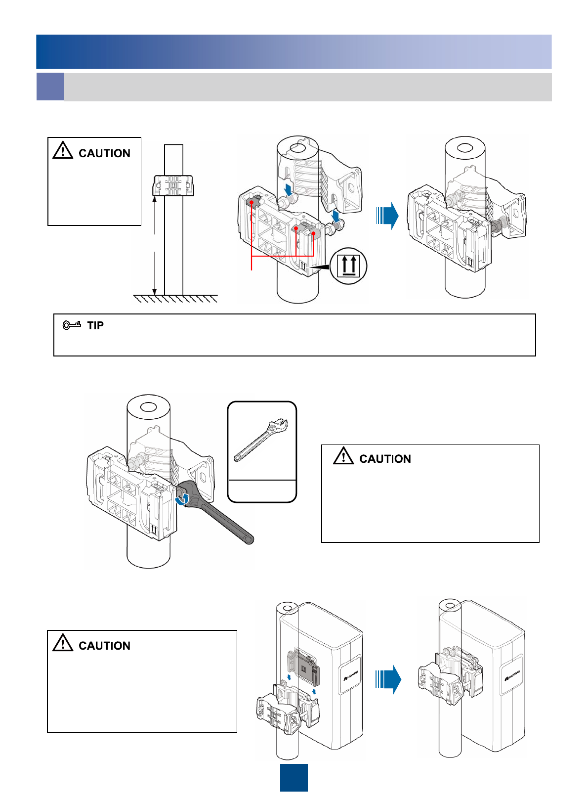
1200 mm~1600 mm
Contact piece
40N•m
When installing the
main bracket,
ensure that the
contact piece on
the bracket is fixed.
You may fit one end of the auxiliary bracket on one dual-nut bolt assembly and then the other end on the
other dual-nut bolt assembly during the installation.
Fasten the two dual-nut bolt assemblies
alternatively. After the brackets are secure,
use a tape to measure the spacing between
the main bracket and the auxiliary bracket at
the two sides and ensure that the spacing is
the same.
zThe weight-bearing capacity of the RF
ports at the bottom of the RRU is low. Do
not place the RRU at its bottom.
zDuring the operation, place the foam
pad or cardboard under the RRU to
prevent any damage to the housing of
the RRU.
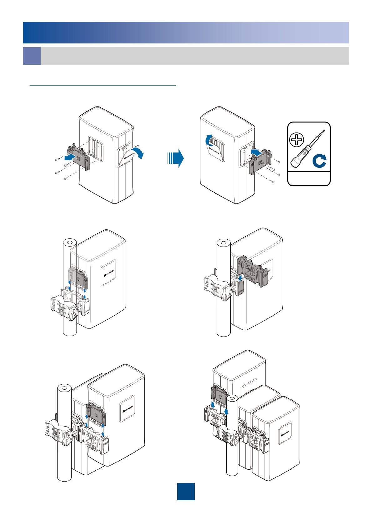
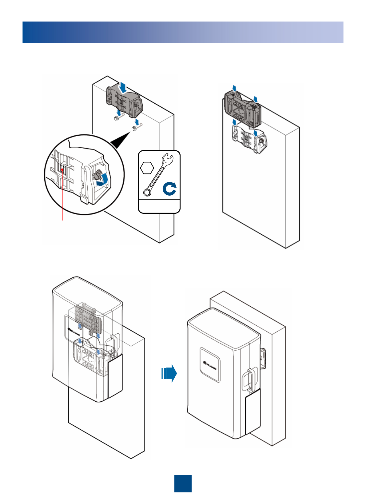
3. Install the RRU on the main bracket. When you hear click sound, you can infer that
the RRU is in position.
2. Use an adjustable wrench to tighten the nut until the fastening torque is 40 N·m. In
this way, the main and auxiliary brackets are secured on the pole.
1. Install the main bracket.
Installing the RRU on a Metal Pole
aInstalling a Single RRU on a Metal Pole
9
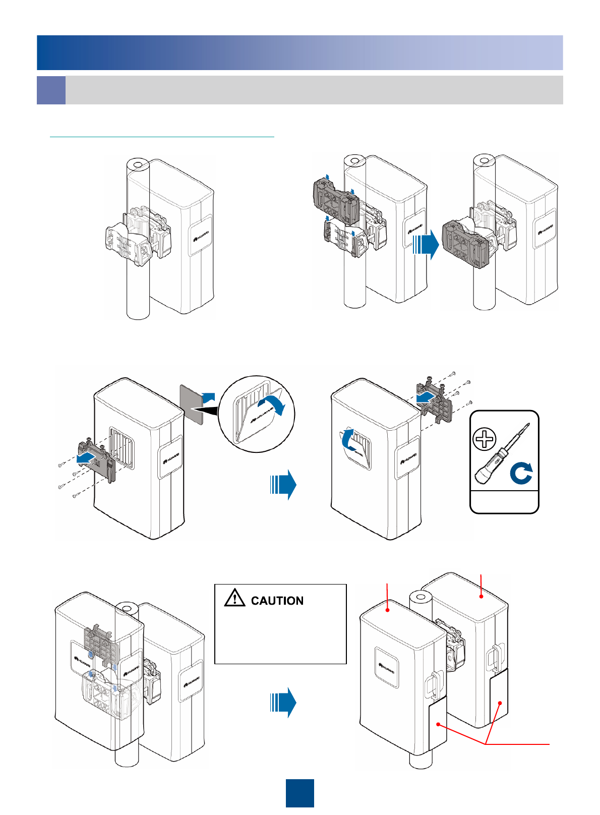
Cabling cavity
In standard mode In reverse mode
Installing the RRU on a Metal Pole
Installing Two RRUs Back-To-Back on a Metal Pole
b
4. Install the second RRU on the main bracket.
3. Reinstall the attachment plate and cover plate on the second RRU by interchanging
their positions.
1. Install an RRU. For details, see page 8
Installing a Single RRU on a Metal Pole.2. Install the main fixture for another RRU.
Ensure that the cabling
cavities of the two RRUs
face the same direction
when installing the RRUs.
4.8N•m
M6X16
10
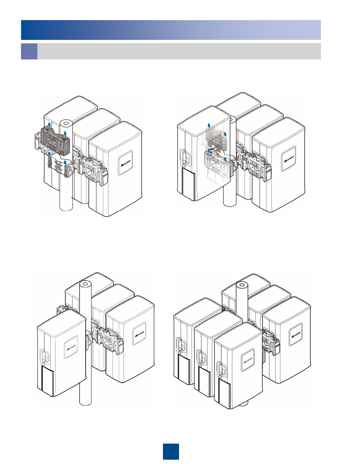
Installing the RRU on a Metal Pole
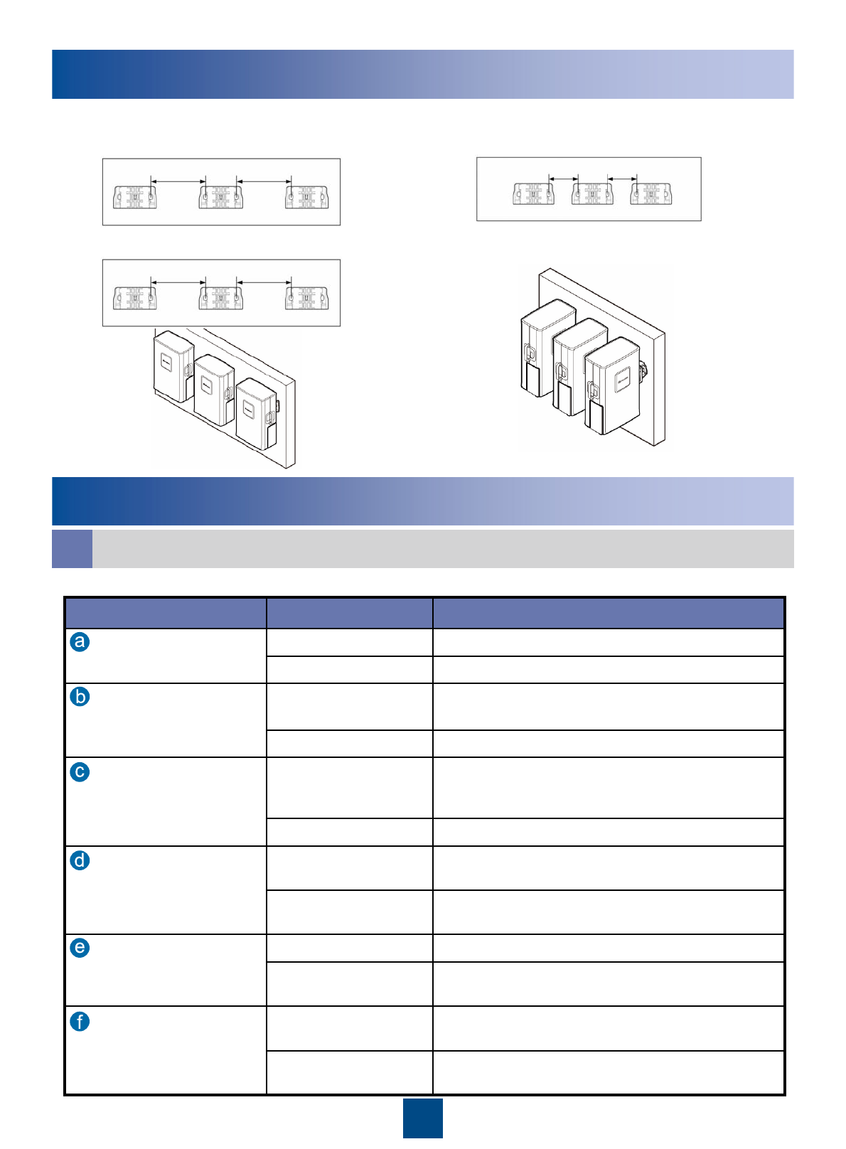
Installing Multiple RRUs in Centralized Mode
c
2. Relocate the attachment plate.
1. Install the main fixture and the auxiliary fixture. For details, see page 8
Installing a Single RRU in Ordinary Mode.
4. Install the second main fixture.3. Fit the tabs on the attachment plate of the
RRU into the anchor slots on the main fixture.
5. Fit the tabs on the attachment plate of
the second RRU into the anchor slots on
the second main fixture.
6. Install the third RRU.
4.8N•m
M6X16
11
7. Install the fourth main fixture. 8. Fit the tabs on the attachment plate of
the fourth RRU into the anchor slots on
the fourth main fixture.
Installing the RRU on a Metal Pole
Installing Multiple RRUs in Centralized Mode
c
9. Four RRUs installed in centralized mode. 10. Six RRUs installed in centralized mode.
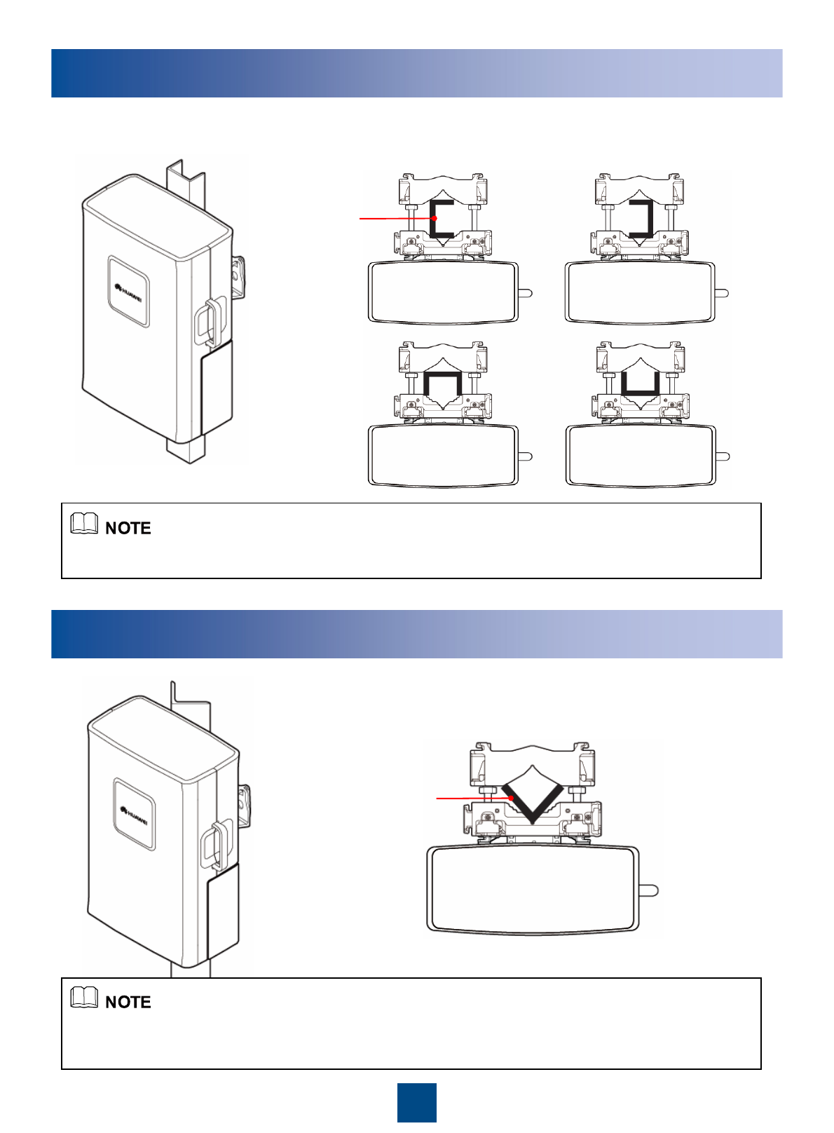
12
U-steel
Installing the RRU on a U-Steel
Plan view
Plan view
Angle steel
zThe procedure for installing the RRU on a U-steel is the same as that for installing the RRU on a metal pole.
zIt is recommended that only one RRU be installed on a U-steel.
zThe procedure for installing the RRU on an angle steel is the same as that for installing the RRU on a metal
pole.
zIt is recommended that only one RRU be installed on an angle steel.
Installing the RRU on an Angle Steel
13
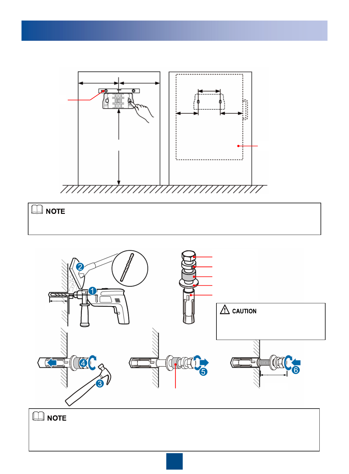
1200 mm to 1600 mm
≥600 mm ≥600 mm 128 mm
79 mm 79 mm
RRU
Level
Ø14
After the expansion bolt is removed,
dispose of the plastic tube.
90°
55 mm to 60mm
20 mmto 30 mm
Installing the RRU on a Wall
1. Place the auxiliary bracket at the installation position. Use a level to check that the
auxiliary bracket is placed horizontally. Then, mark the anchor points by using a
marking pen.
zIt is recommended that the auxiliary bracket be 1,200 mm to 1,600 mm above the ground.
zThe RRUs cannot installed on a wall in centralized mode. Therefore, expansion bolt assemblies should be
prepared for each RRU.
2. Drill holes at the anchor points and then install the expansion bolt assemblies.
When the RRU is installed on a wall, the requirements are as follows:
zFor one RRU, the wall has a weight-bearing capacity of 76 kg.
zThe fastening torque of the expansion bolt reaches 30 N·m, the expansion bolt works properly, and no
damages such as cracks are on the wall.
M10x65 bolt
Spring washer 10
Plastic tube
Flat washer 10
Expansion tube
Do not hammer the bolt entirely into the
wall. Instead, leave 20 mm to 30 mm of
the bolt outside the wall.
14
Arrows are upwards
30N•m
M10
Installing the RRU on a Wall
3. Fit the auxiliary bracket on the expansion
bolts downward, and then tighten the bolts
by using a combination wrench 17 mm.
4. Install the main bracket.
5. Install the RRU.
15
Installing the RRU on a Wall
6. Install multiple RRUs.
≥70 mm
560 mm 560 mm
≥70 mm
≥760 mm ≥760 mm
Minimum Clearance:
Recommended Clearance :
Installing the RRU Cables
RRU Cable Connections
a
Standard AISG female connector of the AISG multi-wire cableStandard AISG male
connector
Standard AISG male connector of the AISG extension cable or
RCU
Standard AISG female
connector
Port labeled RET/MON on the RRUWaterproof DB9 connectorAISG multi-wire cable between
the RRU and the RCU
The connectors labeled 2A and 2B are connected to port labeled
CPRI0, CPRI1 or CPRI2 on the LBBP board of the BBU.
DLC connector
CPRI optical cable The connectors labeled 1A and 1B are connected to the optical
module on the port labeled CPRI_W on the RRU
DLC connector
AISG extended cable between
the RRU and the RCU
Standard AISG male connector of the RCUStandard AISG female
connector
The blue OT terminal is connected to socket labeled NEG(-)0 in
the RRU cabling cavity. And the black OT terminal is connected
to socket labeled RTN(+)0.
Two OT terminals
(M4)
DC RRU power cable
(North American standard: 3.3 mm2
European standard:
4 mm2 )External power supplyBare wire
Feeder or antennaDIN male connector
Ports labeled ANT_TX/RXA and ANT_TX/RXB on the RRU
(Only the ANT_TX/RXA port supports the OOK signal).
DIN male connectorRRU RF jumper
Nearest grounding barOT terminal(M8)
Grounding bolt on the RRUOT terminal(M6)PGND cable
(16mm2 )
Connector to…Connector TypeCable
Cable List
16
Installing the RRU Cables
RCU
zWhen the length of the AISG multi-wire cable is
not enough, you can choose the optional AISG
extension cable.
zIf the coaxial cable is used for the RET antenna
when the STMA or Smart Bias-Tee (SBT) is used,
the OOK signals are required. Therefore, the RET
control signal cable needs to be connected to the
ANT_TX/RXA port.
Antenna
Single RRU
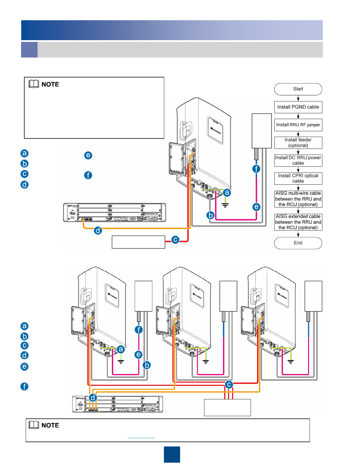
RRU Cable Connections
a
External power
system
Multiple RRUs
External power
system
Antenna
Antenna
Antenna
For detail information of the cable, see Cable List on Page 15.
PGND cable
RRU RF jumper
DC RRU power cable
CPRI optical cable
AISG multi-wire cable between
the RRU and the RCU
AISG extended cable between
the RRU and the RCU
PGND cable
RRU RF jumper
DC RRU power cable
CPRI optical cable
AISG multi-wire cable
between the RRU and
the RCU
AISG extended cable
between the RRU and
the RCU
17
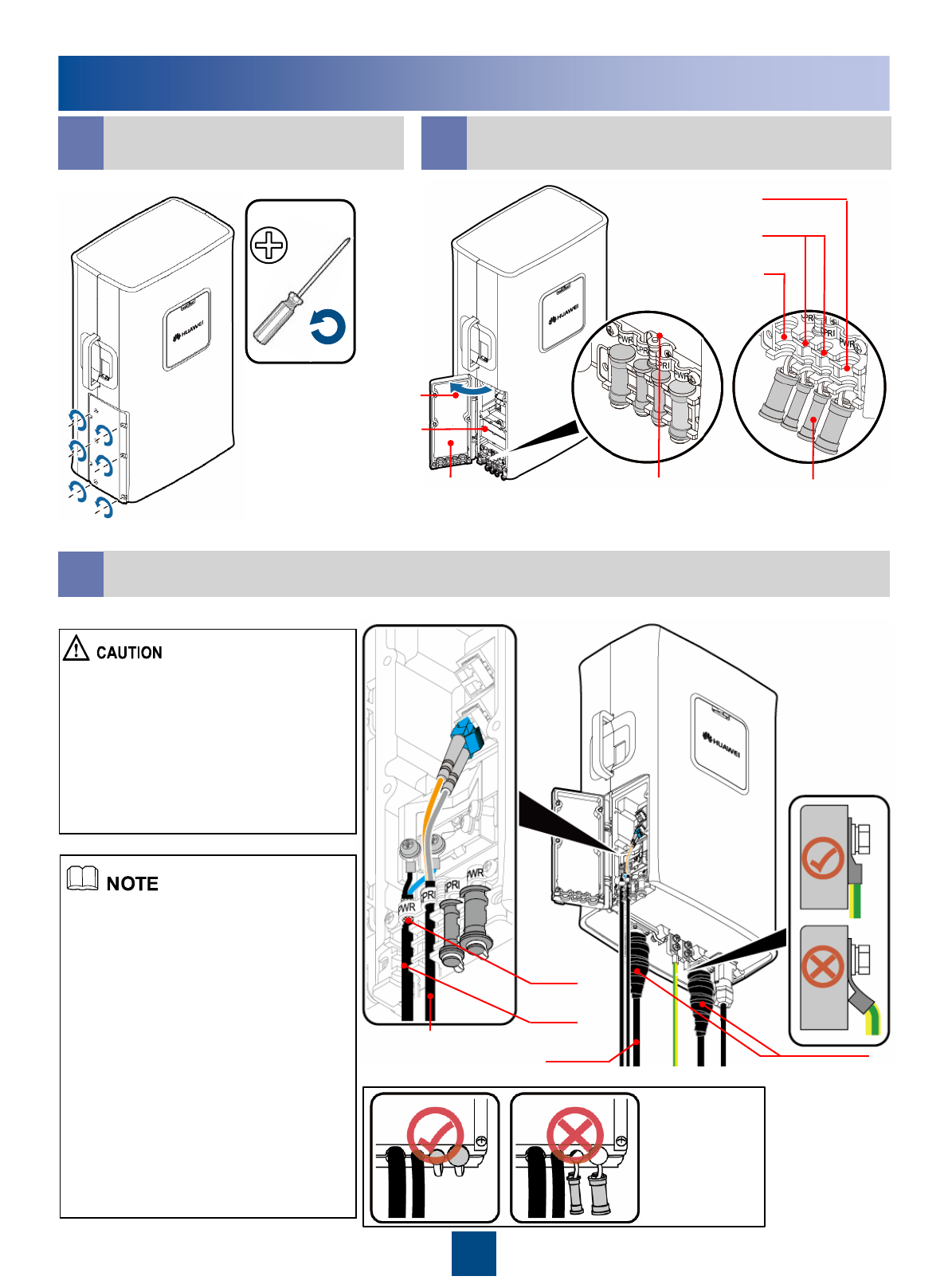
Installing the RRU Cables
b c Cabling Cavity of the RRU
Opening the Cover Plate
of the RRU Cabling Cavity
Waterproofing filler
Cable troughs for
optical cables
Cable troughs for
power cables
Cabling cavity
Cover plate of the
cabling cavity
Label for preparing
the power cable
cable clip
Cable troughs for
power cables
dCable Connections on the RRU
zUse the power cable clip to press the
shielding layer tightly and ensure that
the lower part of the shielding layer does
not exceed the position shown in the
preceding figure.
zGround the shielding layer at the
other end of the power cable.
zDo not remove the dustproof cap from
the idle antenna port, and use the
waterproof tape to wrap the joint.
zFor details on how to add OT
terminals to the power cable of the RRU,
see page 23 " Adding OT Terminals by
Using a Wire Stripper."
zWhen wrapping the waterproof tape,
apply even force to extend the tape until
the width of the tape is 1/2 of the
original width.
zWrap the joint spirally upward,
downward, and then upward again. In
other words, the joint is wrapped by
three layers of the tape. Ensure that the
two immediate layers overlap with each
other about half the width of the tape.
For details, see page 25 “Waterproofing
Outdoor Cables.”
zInstall the optical module before
installing the optical cables. For details,
see page 25 “Installing the Optical
Module.”
After the cables
are installed on
the RRU, insert
the waterproofing
fillers into the idle
cable troughs.
CPRI optical cable RF jumper
Power cable
Shielding
layer of the
power cable
First wrap the joint
with the waterproof
tape, and then
wrap the joint with
the PVC insulating
tape.
M4
18
Installing the RRU Cables
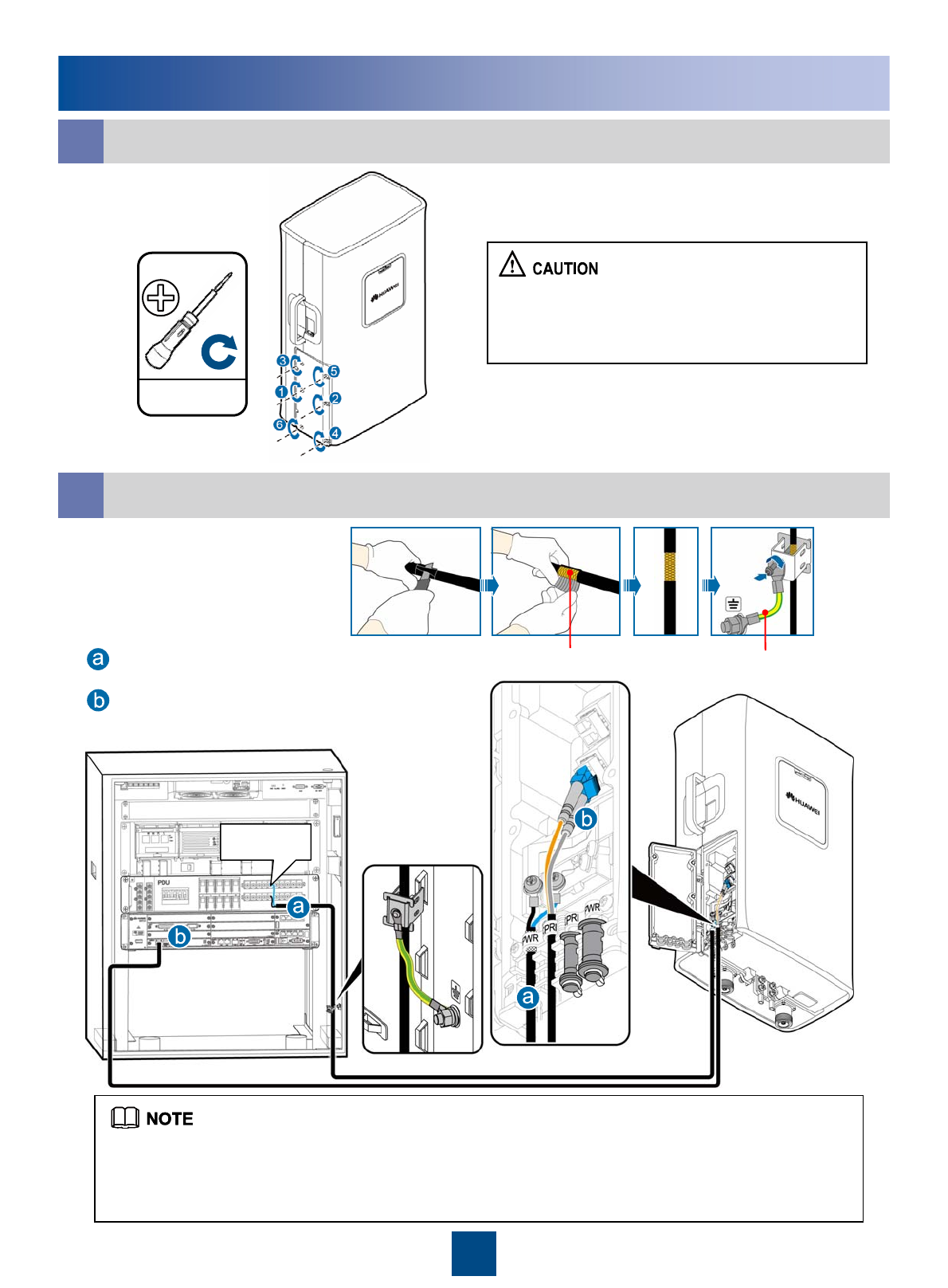
eClosing the Cover Plate of the RRU Cabling Cavity
zThe screws on the cover plate should be
tightened until the fastening torque is 1.4 N·m.
zTighten the screws on the cover plate of the
cabling cavity in the sequence shown in the figure.
f
Metal Shielding layer (25 mm) PGND cable
Grounding the shielding layer
of the power cable:
DC RRU power cable
CPRI optical cable
RRU+APM30/APM30H (Ver.A)
zThe DC RRU power cable is connected to one of the LOAD4 to LOAD9 terminals of the PDU.
zStrip the jacket of the DC RRU power cable for a small part, press the exposed shielding layer on the
strap, and then connect the PGND cable on the strap to the nearest grounding bolt on the side in the
APM30/APM30H(Ver.A).
1.4N•m
M4
LOAD4
19
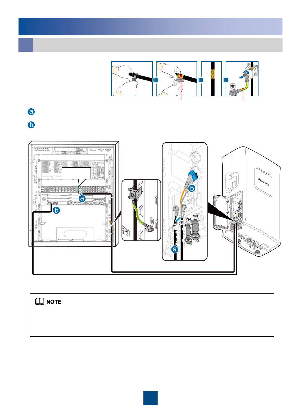
Installing the RRU Cables
g
LOAD0
Metal Shielding layer (25 mm) PGND cable
Grounding the shielding layer
of the power cable:
zStrip the jacket of the DC RRU power cable for a small part, press the exposed shielding layer on the
strap, and then connect the PGND cable on the strap to the nearest grounding bolt on the side in the
APM30.
zThe DC RRU power cable is connected to one of the LOAD0 to LOAD5 terminals of the DCDU-03B.
DC RRU power cable
CPRI optical cable
RRU+APM30(+24V) / APM30H(Ver.B, +24V)
20
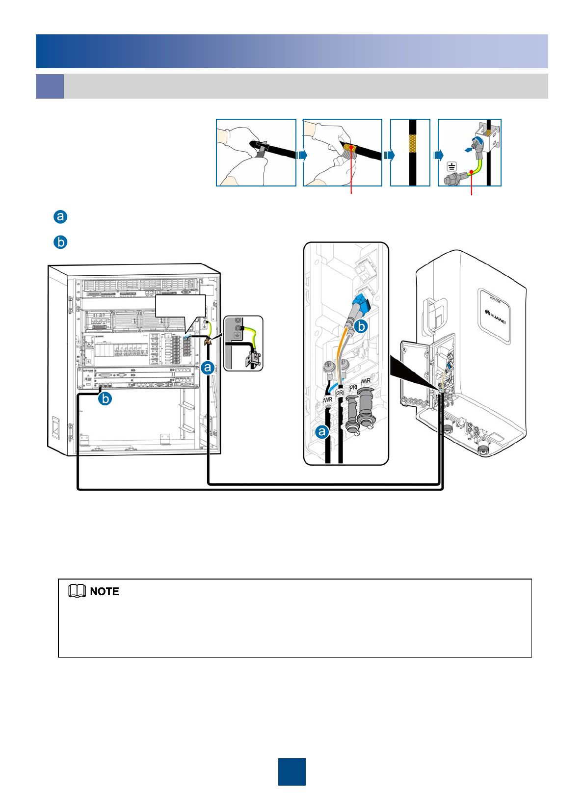
Installing the RRU Cables
hRRU+APM30H (Ver.B)
Metal Shielding layer (25 mm) PGND cable
Grounding the shielding layer
of the power cable:
zThe DC RRU power cable is connected to one of the RRU0 to RRU5 terminals of the PDU.
zStrip the jacket of the DC RRU power cable for a small part, press the exposed shielding layer on the
strap, and then connect the PGND cable on the strap to the nearest grounding bolt on the side in the
APM30H(Ver.B).
DC RRU power cable
CPRI optical cable
RRU0
21
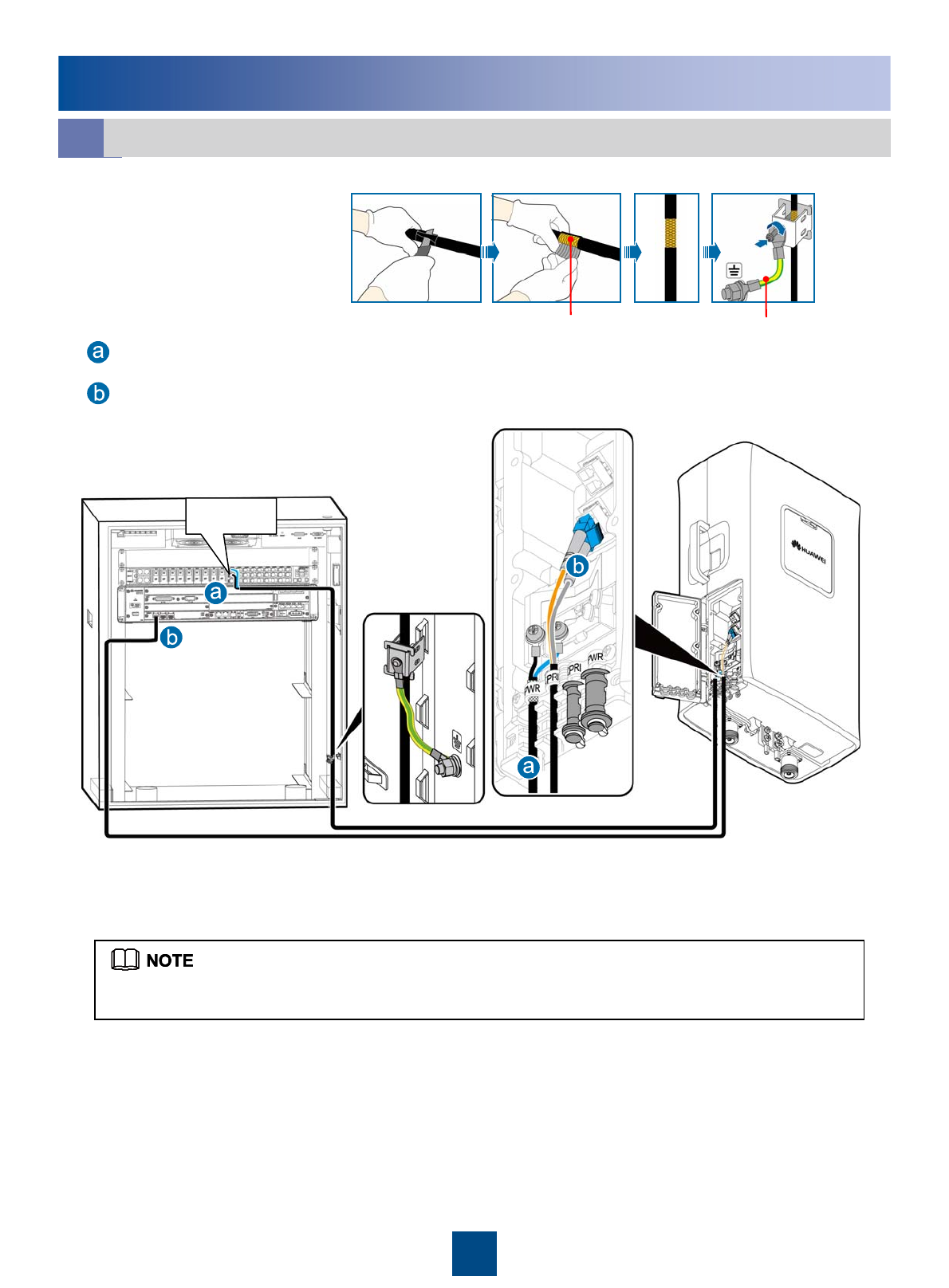
Installing the RRU Cables
LOAD0
iRRU+TMC
Metal Shielding layer (25 mm) PGND cable
Grounding the shielding layer
of the power cable:
The DC RRU power cable is connected to one of the LOAD0 to LOAD5 terminals of the DCDU-03B.
DC RRU power cable
CPRI optical cable
22
Installing the RRU Cables
j
LOAD0
Metal Shielding layer (25 mm) PGND cable
Grounding the shielding layer
of the power cable:
The DC RRU power cable is connected to one of the LOAD0 to LOAD5 terminals of the DCDU-03B.
DC RRU power cable
CPRI optical cable
RRU+TMC11H(Ver.A) / TMC11H(Ver.B)
23
Installing the RRU Cables
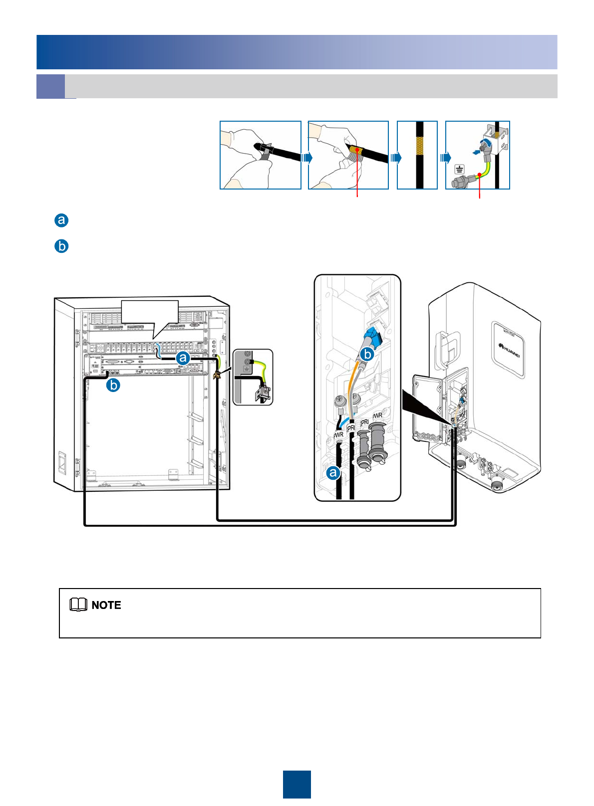
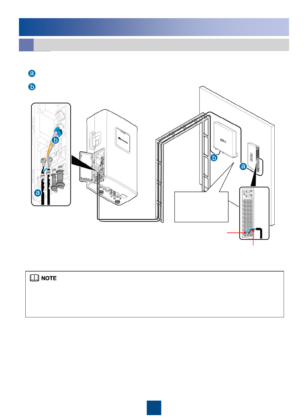
k
LOAD0
shielding layer
zWhen connecting the DC RRU power cable to the DCDU-03B you must add an OT terminal to the shielding
layer. Then, fix the OT terminal to the corresponding GND terminal of the DCDU-03B. For details on how to
add an OT terminal, see page 27 Adding OT Terminals to the Shielding Layer of the DC RRU Power Cable.
zThe DC RRU power cable is connected to one of the LOAD0 to LOAD5 terminals of the DCDU-03B.
DCDU panel facing
the side, and the
BBU panel facing
downward
RRU+BBU Installed Against the Wall
DC RRU power cable
CPRI optical cable
24
RRU Hardware Installation Checklist
No joint lies in the middle of the power cable or the PGND cable.5
The connectors of signal cables are intact and securely linked. And the signal cables are not damaged or broken.10
All labels, tags, and nameplates are correct, legible, and complete. All the labels at both ends of the cables, jumpers
and feeders are legible.
11
The working grounding and protection grounding of the base station and the lightning protection grounding of the
building share one group of grounding conductors.
9
The power cable, PGND cable and other cables need to be bound separately.8
The power cable and PGND cable are not short-circuited or reversely connected and are not damaged or broken.7
The lugs at both ends of the power cable or the PGND cable are securely soldered or crimped.6
Waterproof check: The empty cable troughs in the cabling cavity of the RRU are waterproofed. The cover plate is
tightly buckled on the cabling cavity of the RRU. The RF ports that are not connected with RF cables are capped and
waterproofed. The waterproof caps are fastened.
4
The cover plate is fastened to the RRU cabling cavity.3
The RRU is properly installed.2
The position for each equipment conforms to the engineering design and meets the space requirement. Sufficient
space is reserved for equipment maintenance.
1
ItemsNo.
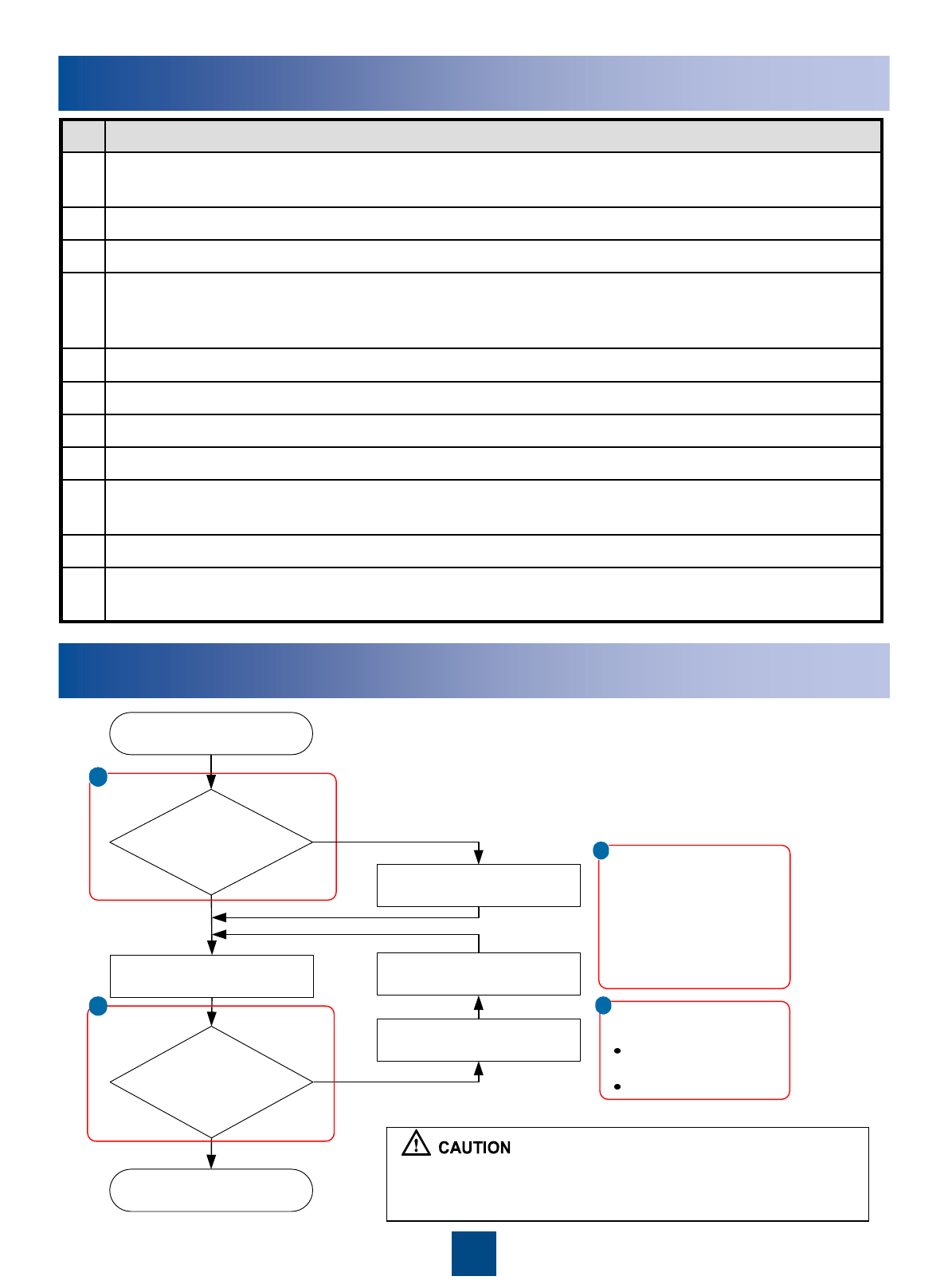
Powering On the RRU
When the RRU is unpacked, it must be powered on within 24
hours. Each time the RRU is maintained after being put into use,
the power-off duration cannot exceed 24 hours.
a
b
Start
Check
whether the input
voltage of the RRU is
normal?
End
Power on the RRU
Check
whether the status of
the LEDs on the RRU
is normal?
Rectify the fault
Power off the RRU
Rectify the fault
Yes
No
aNormal input voltage of the
RRU:
If the BBU is supplied with
-48 V DC power, the
external input power
voltage ranges from -57 V
DC to -36 V DC.
Normal status of the
LEDs on the RRU:
RUN LED: ON for 1s
and OFF for 1s
ALM LED: OFF
b
Yes
No
25
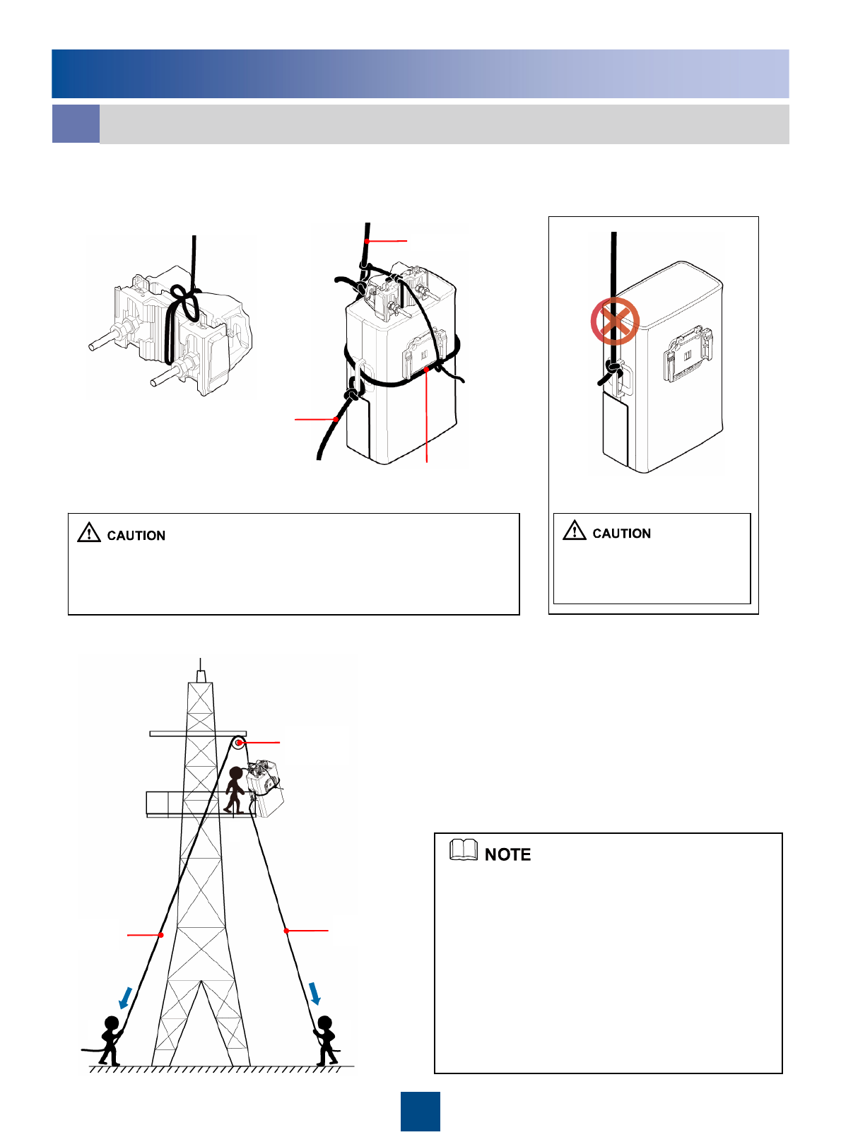
A
B C
Lifting rope
Lower part of the
adapting piece
Steering rope
aBinding the RRU and Installation Components
1. Bind the RRU by leading the lifting rope along the lower part of the adapting piece and
through the handle, bind the main and auxiliary brackets with the lifting rope, and then
bind the steering rope with the handle of the RRU, as shown in the following figures.
2. Lift the RRU and installation components to the tower.
Do not bind the lifting rope
only on the handle when
lifting the RRU.
zWhen lifting the RRU and installation components to the tower,
prevent the RRU from colliding with the tower.
zLift the RRU to the tower before it is installed on the metal pole,
angle steel, or U-steel.
zInstaller A climbs onto the tower. Then, installer
A fixes the pulley to the support of the tower
platform and leads the lifting rope through the
pulley.
zInstaller C uses a lifting rope to bind the RRU
and installation components as shown in the
preceding figure and then ties a knot in the steering
rope at the handle of the RRU.
zInstaller B pulls the lifting rope, and at the same
time, installer C pulls the steering rope away from
the tower to prevent the RRU and installation
components from colliding with the tower.
zInstaller A holds the RRU and installation
components and untie the ropes.
Steering rope
Lifting rope
Pulley
Appendix
26
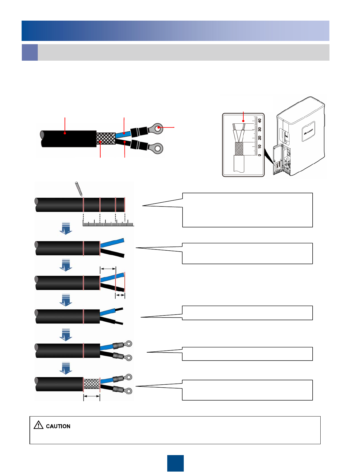
Label for preparing
the power cable
15mm
8mm
14mm
010203040
Adding the OT terminals to the power cable involves adding OT terminals to the DC
RRU power cable and adding OT terminals to the shielding layer of the DC RRU power
cable.
bAdding OT Terminals by Using a Wire Stripper (Recommended)
Determine lengths of power cables for
different operations according to the scales on
the inner side of the cover plate of the cabling
cavity.
Based on the determined length, remove the
jacket and shielding layer off the power cable.
Add an OT terminal to each wire.
Strip a 15 mm jacket off the power cable to
reveal the shielding layer of the power cable
Remove the jacket from each wire.
The OT terminals must be added to the power cable before the RRU is installed on a metal pole.
Appendix
-48V DC power cable -48V DC power wire
GND wire
Shielding layer
OT terminals
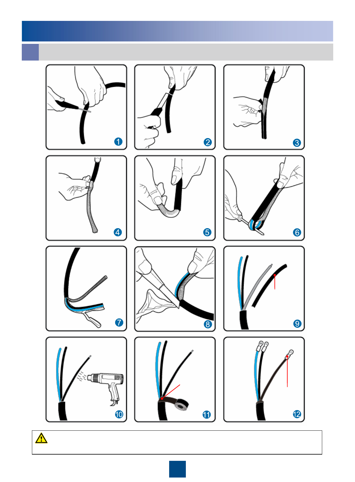
27
Lead the wires
made of the
shielding layers
through heat-
shrinkable tubes.
Wrap the PVC
insulating tape
at the joint
where the three
wires meet. OT terminal on
the shielding
layer
Do not damage the shielding layer of the power cable when cutting around the jacket.
WARNING
Appendix
cAdding OT Terminals to the Shielding Layer of the DC RRU Power Cable
28
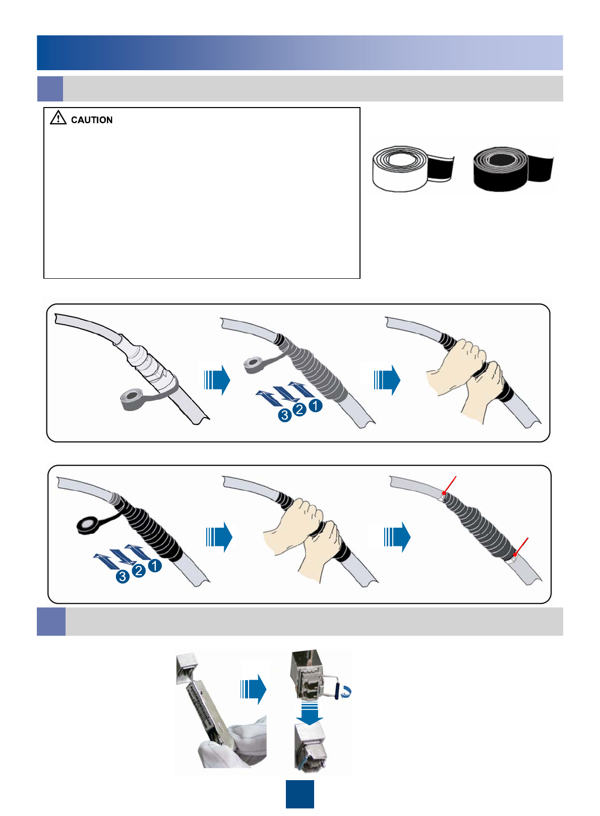
Waterproofing Outdoor Cables
d
zThe waterproof tape should be wrapped for an extra length of 20
mm away from the connectors at both ends.
zThe tapes should be wrapped around the connector from the
lower part to the upper part. When wrapped for another layer, the
tapes may not be cut.
zWhen wrapping the waterproof tape, apply even force to extend
the tape until the width of the tape is 1/2 of the original width.
zWhen wrapping the waterproof tape, ensure that the upper layer
of the tape covers at least 50% of the lower layer.
zThe insulating tape should be wrapped for an extra length of 20
mm away from the connectors at both ends.
zThe last layer of the waterproof tape should be wrapped from the
lower part to the upper part to prevent rainwater from infiltrating into
the tape.
Waterproof tape Insulating tape
Installing the Optical Module
e
Tightly pressing the tape
1. Wrap three layers of waterproof tape.
2. Wrap three layers of insulating tape.
Tightly pressing the tape
Binding cable ties at both
ends of the tape
tie
tie
Appendix
29
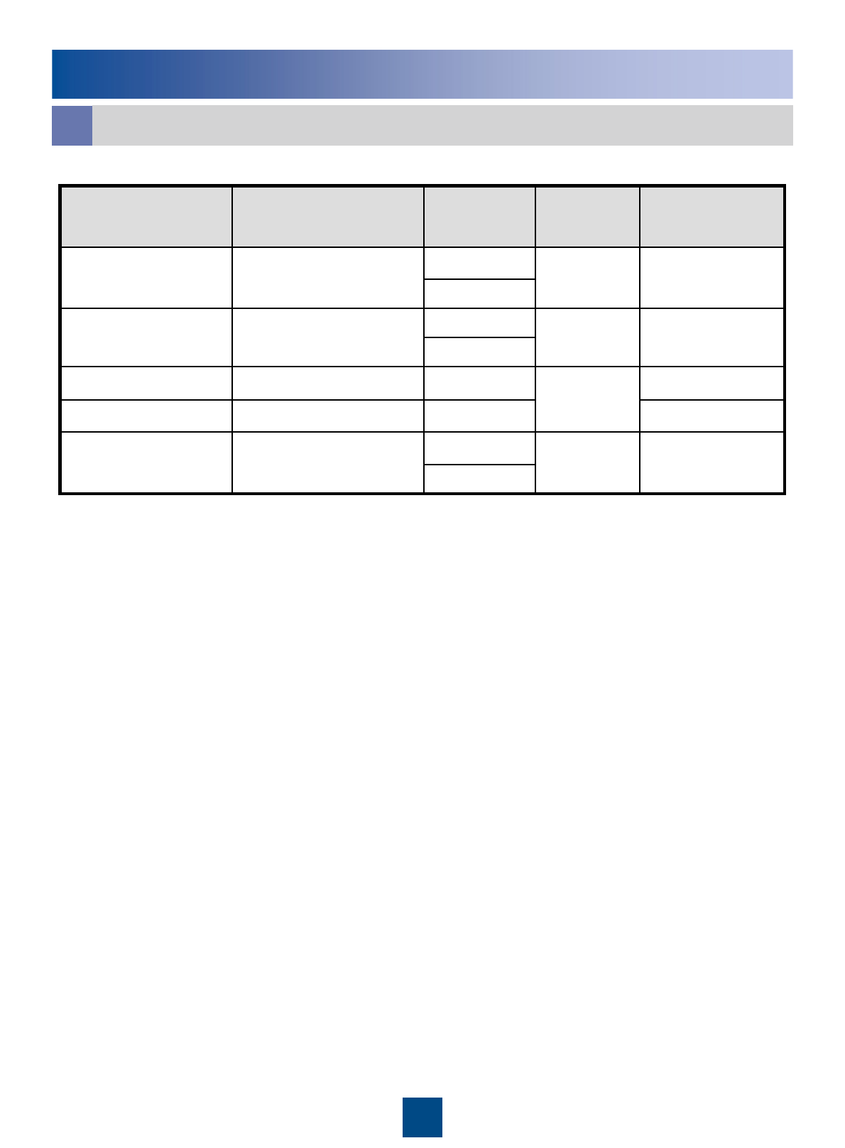
Pin Assignment of the RRU AISG Extension cable
f
Brown
+24VTwisted pairWhite/brownX2.6X1.6
RS485 AGreenX2.5X1.5
RS485 BTwisted pairWhite/greenX2.3X1.3
Orange
DC Return ATwisted pairWhite/orangeX2.7X1.7
Blue
+12VTwisted pairWhite/blueX2.1X1.1
InstructionWire TypeWire ColorPin of the AISG
female connector
Pin of the AISG
male connector
Appendix

30
Change History
z04(2010-03-05)
This is the fourth commercial release.
Compared with issue 03 (2009-12-10) of V200, the description on the cross-section area of the
RRU power cable is added.
z03(2009-12-10)
This is the third commercial release.
Compared with issue 02 (2009-09-25) of V200, the installation scenarios of APM30H(Ver.B),
APM30H(Ver.B, +24V), TMC11H(Ver.B) are added.
z02 (2009-09-25)
This is the second commercial release.
Compared with issue 01 (2009-08-04) of V200, the requirements for installation support
structure are modified.
z01 (2009-08-04)
This is the initial commercial release.
This describes the changes in the RRU3808 Installation Guide.

HUAWEI TECHNOLOGIES CO., LTD.
Huawei Industrial Base Bantian Longgang
Shenzhen 518129
People’s Republic of China
www.huawei.com