Huawei Technologies RRU3832 Remote Radio Unit User Manual Installation Guide
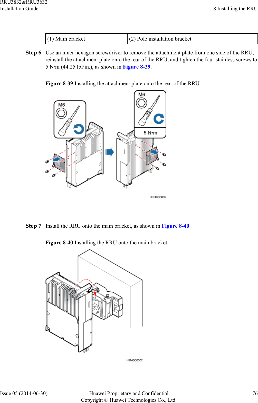
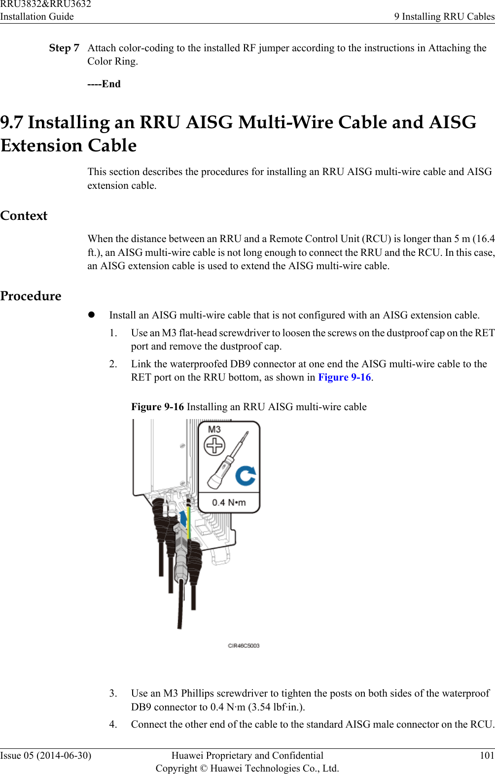
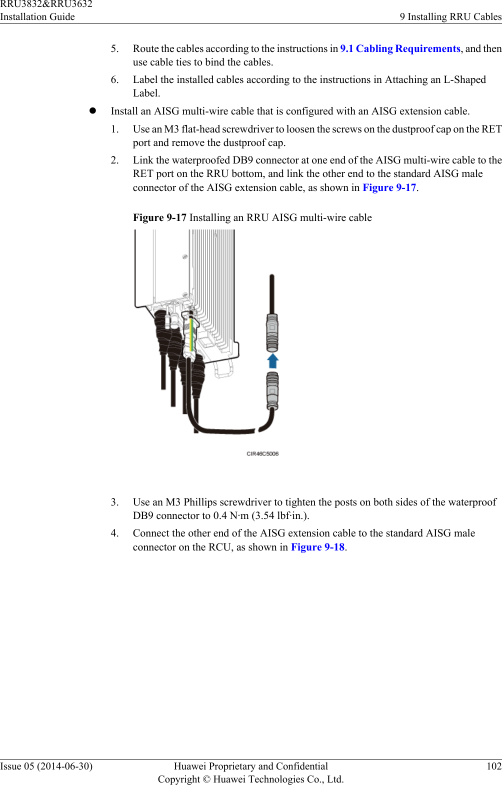
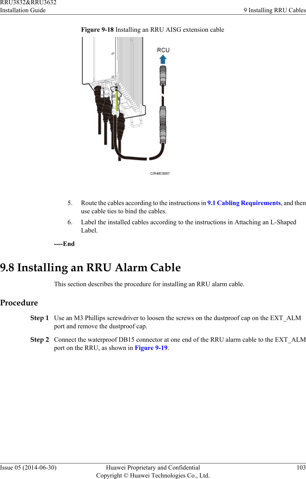
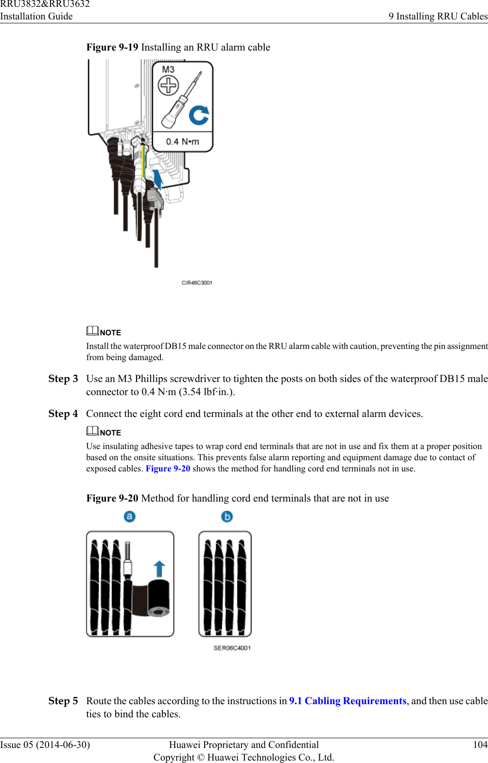
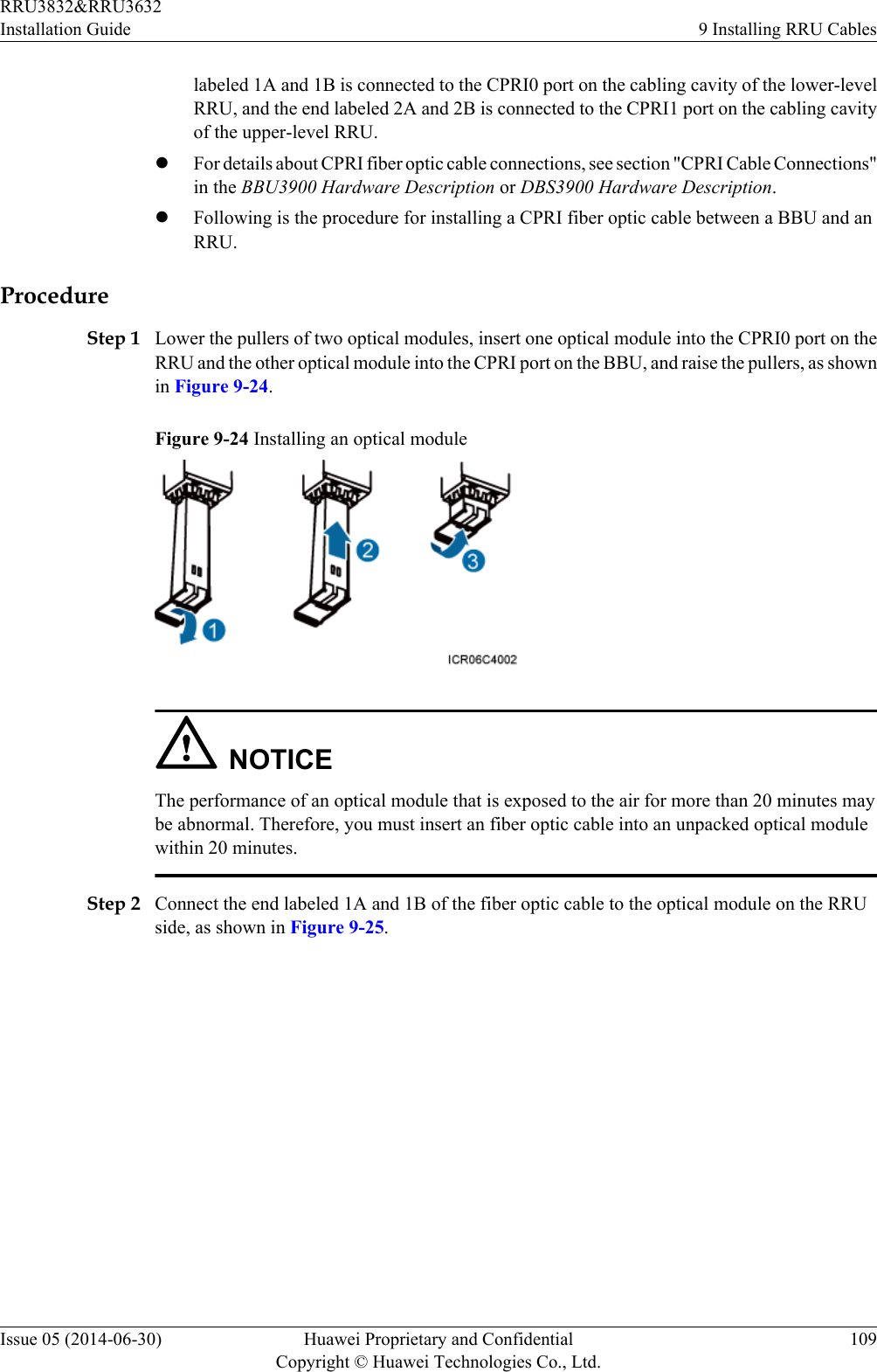
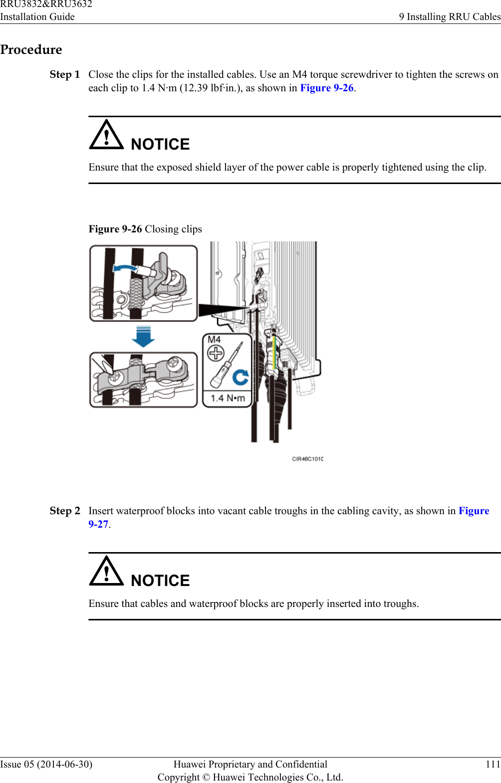
Huawei Technologies Co.,Ltd Remote Radio Unit Installation Guide
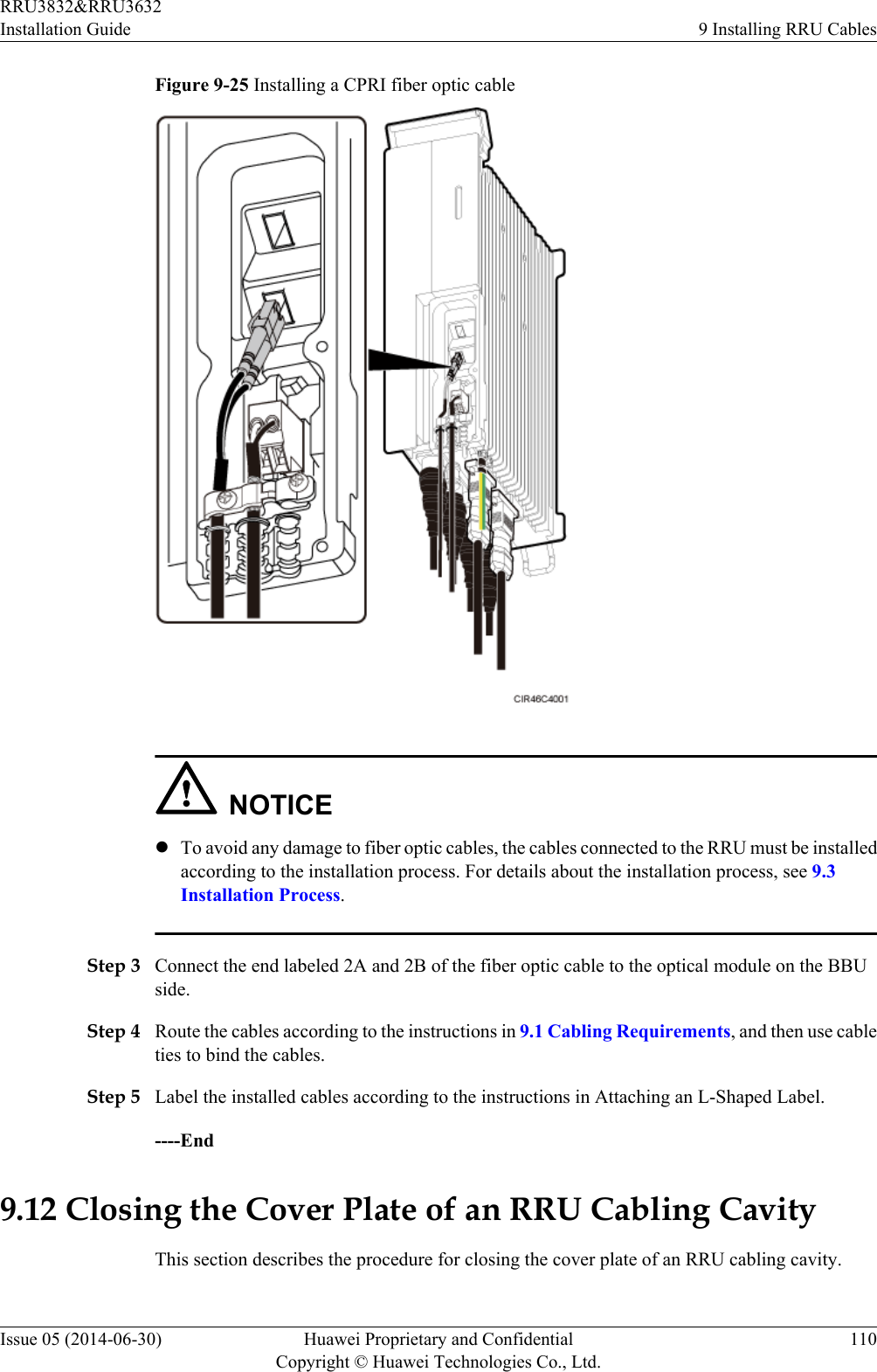
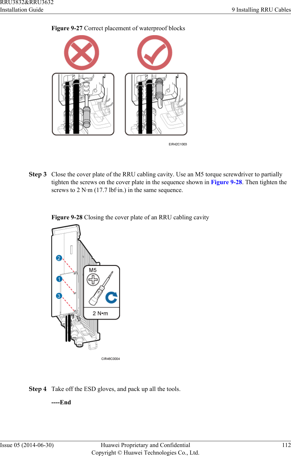
UserManual.wiki
>
Huawei Technologies
>
RRU3832 User Manual
>
User Manual III
Contents
1.
User Manual I
2.
User Manual II
3.
User Manual III
4.
User Manual IV
User Manual III
Navigation menu
Upload a User Manual
Namespaces
Wiki Guide
HTML
PDF
Info
Views
User Manual
Discussion / Help
Navigation
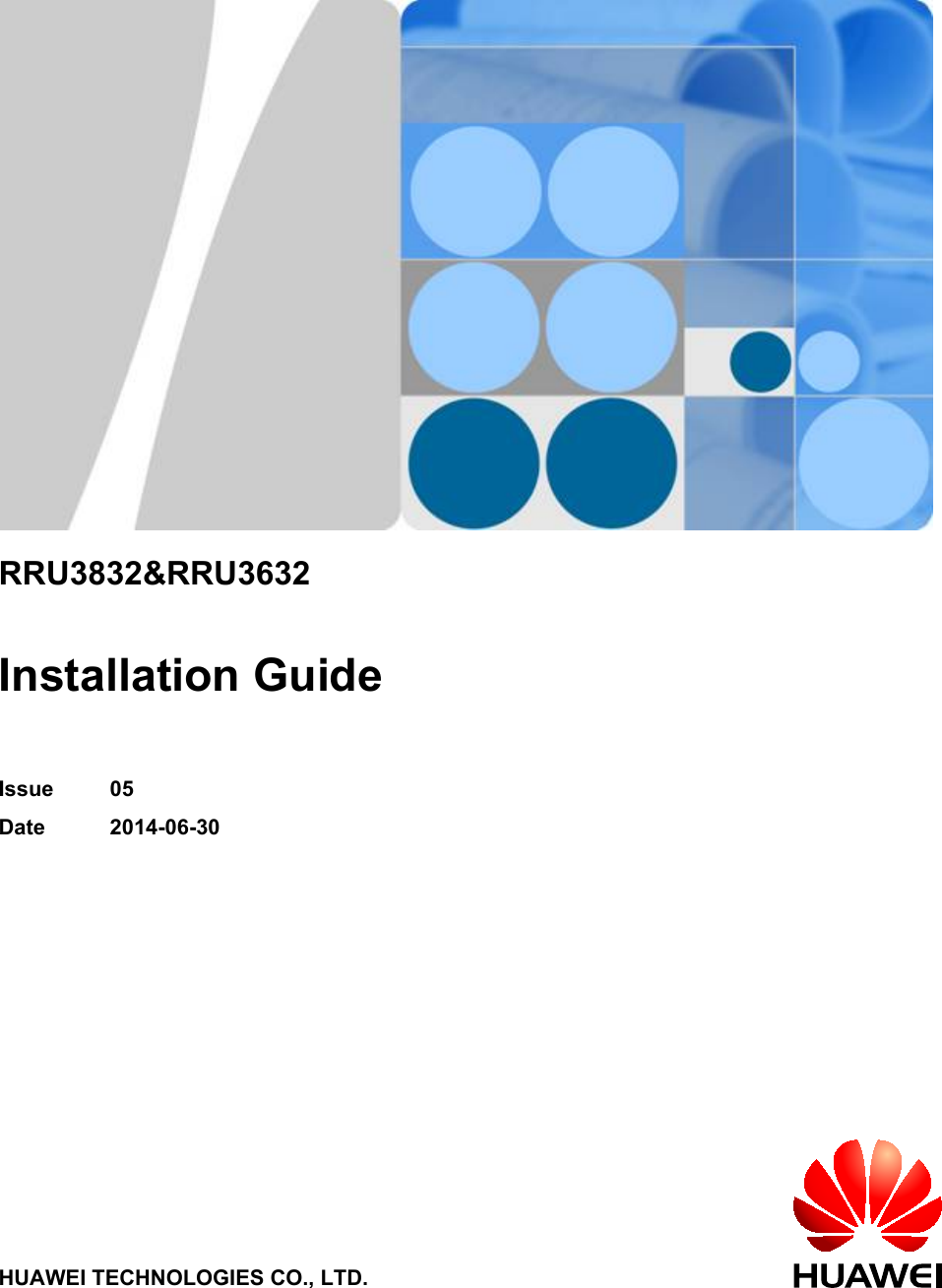
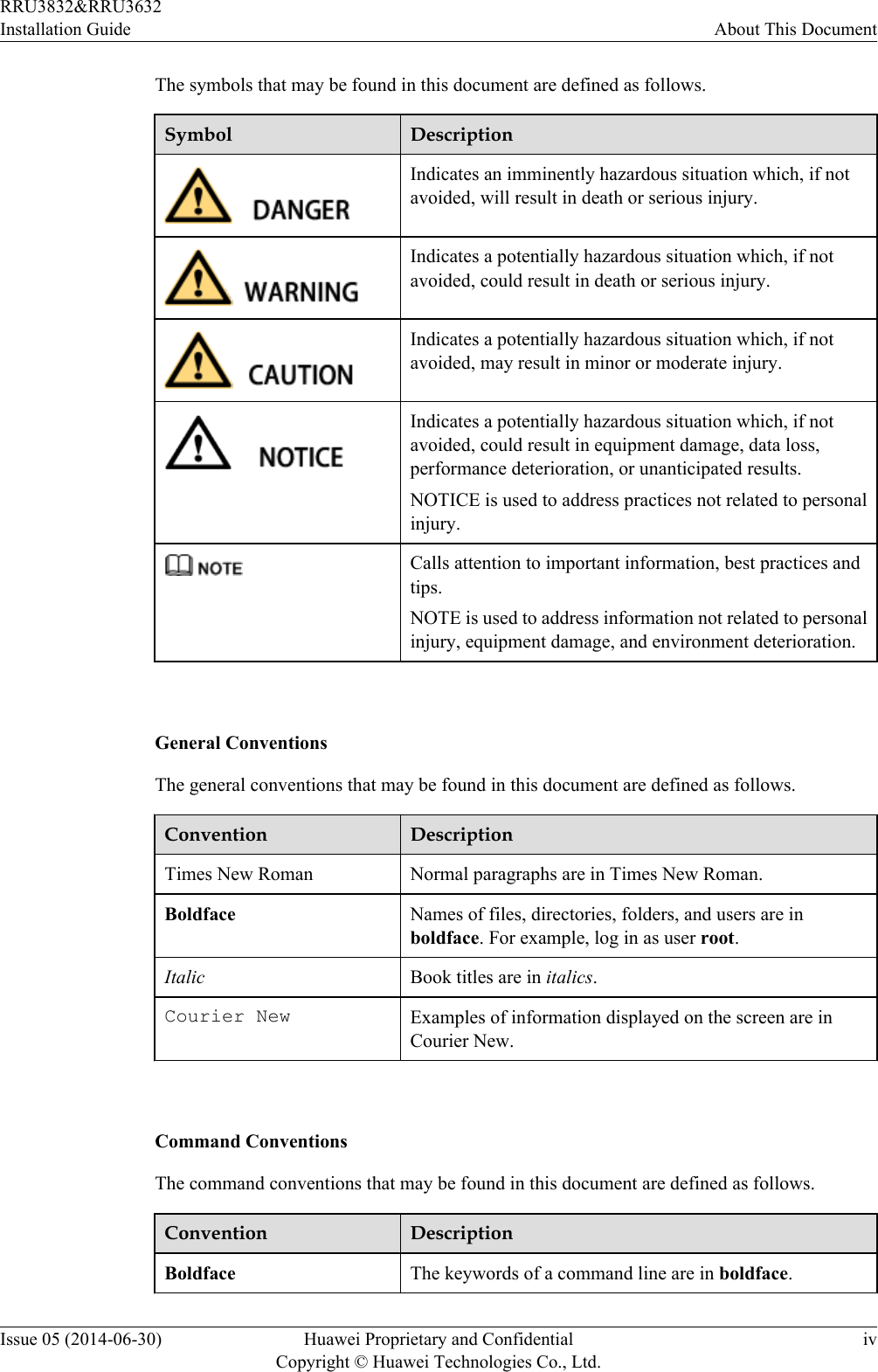
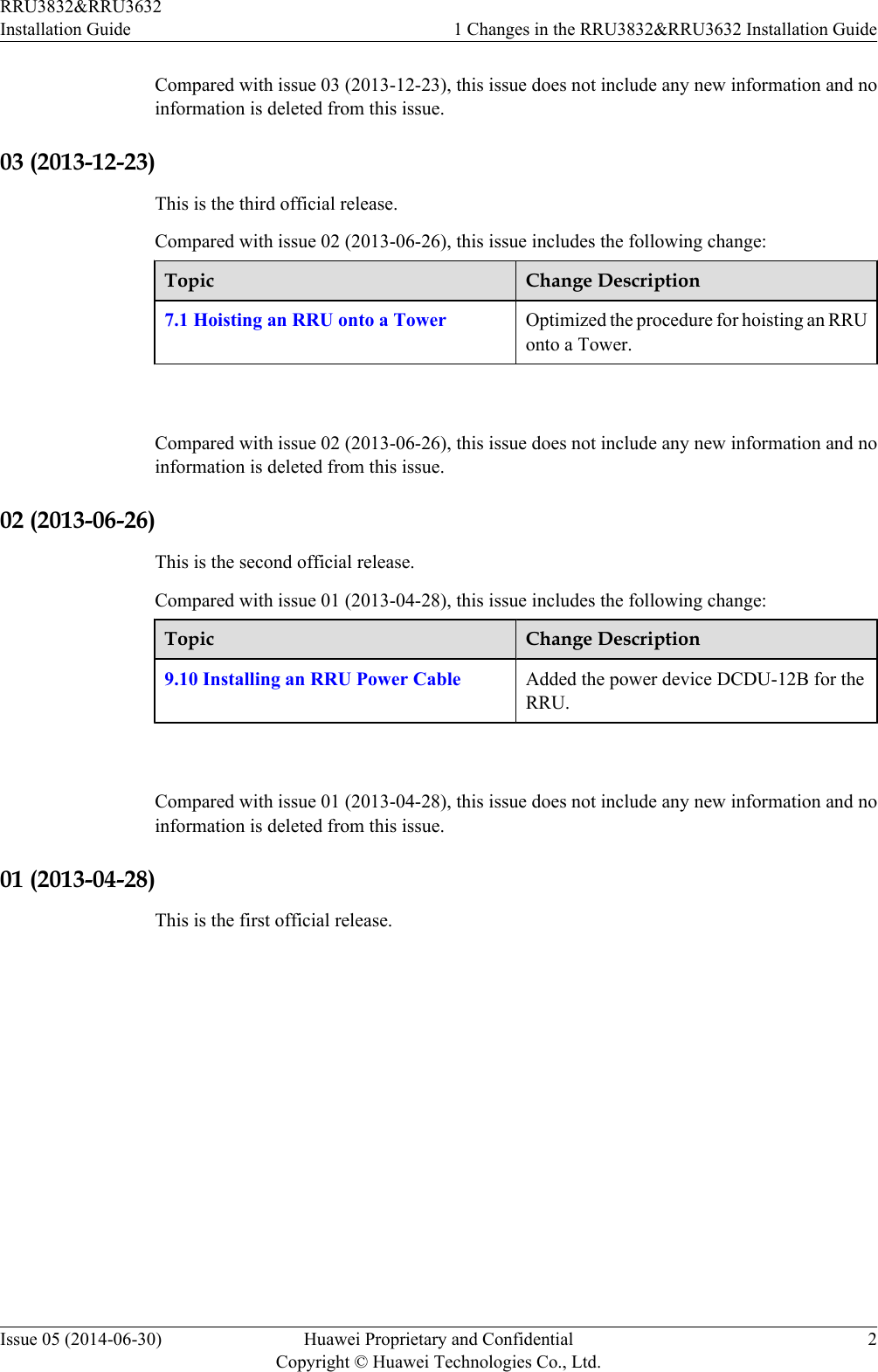
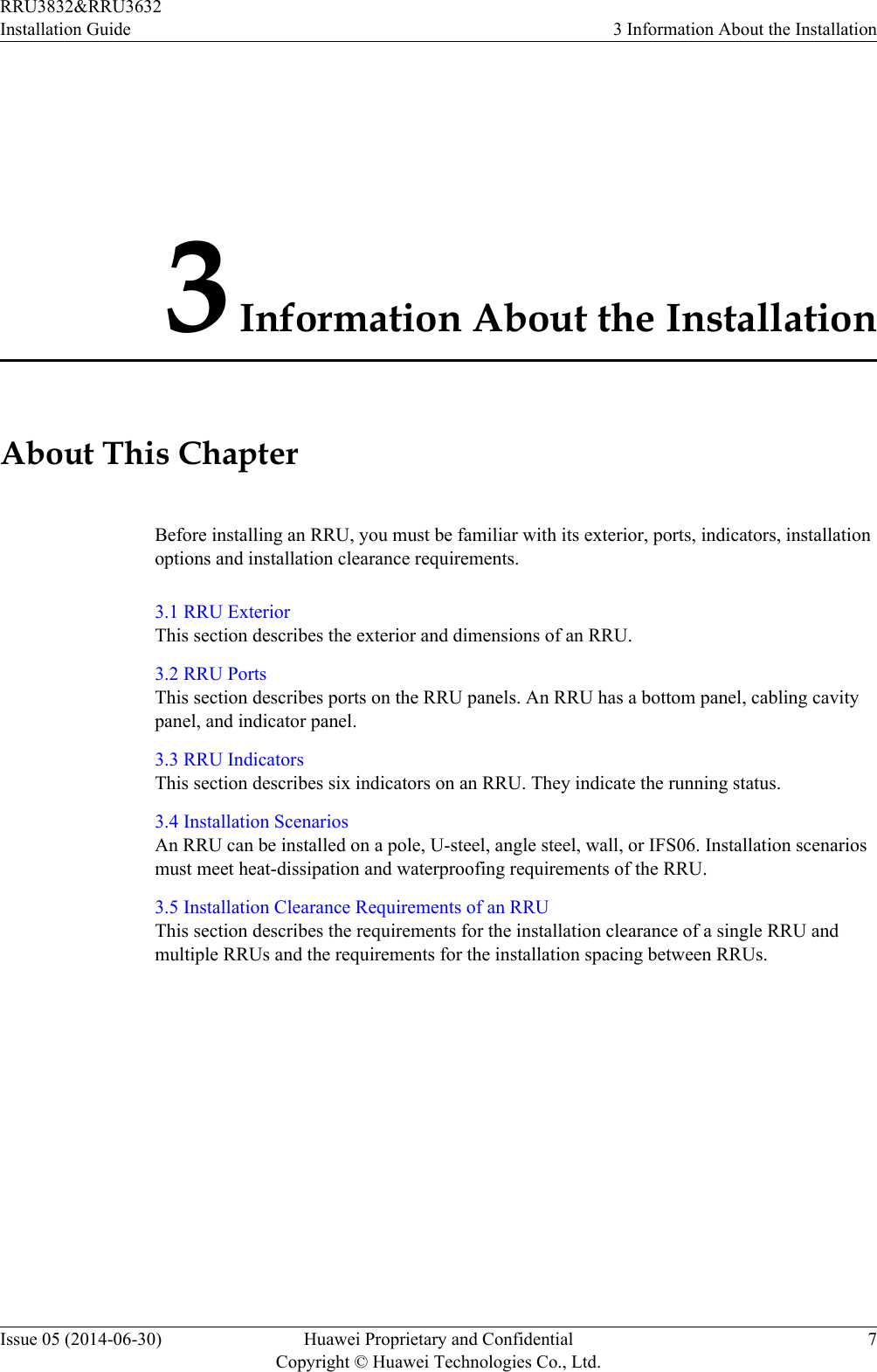
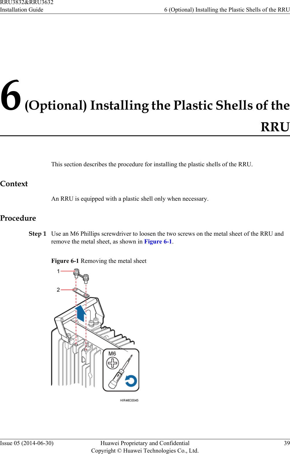
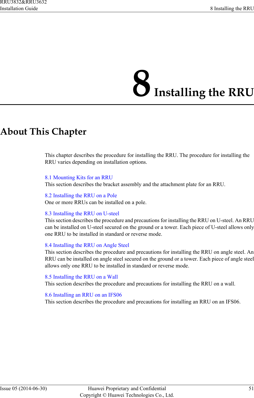
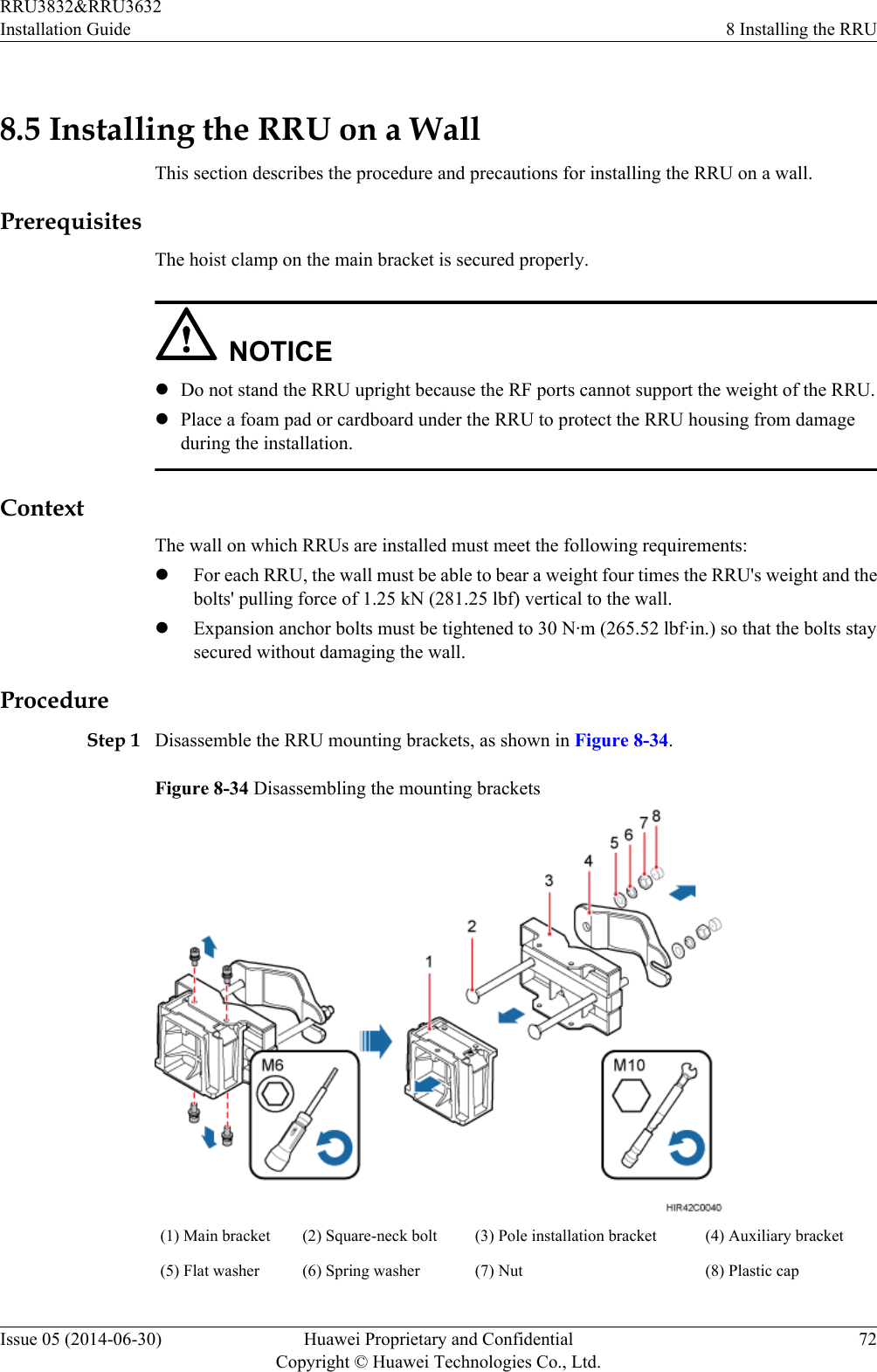
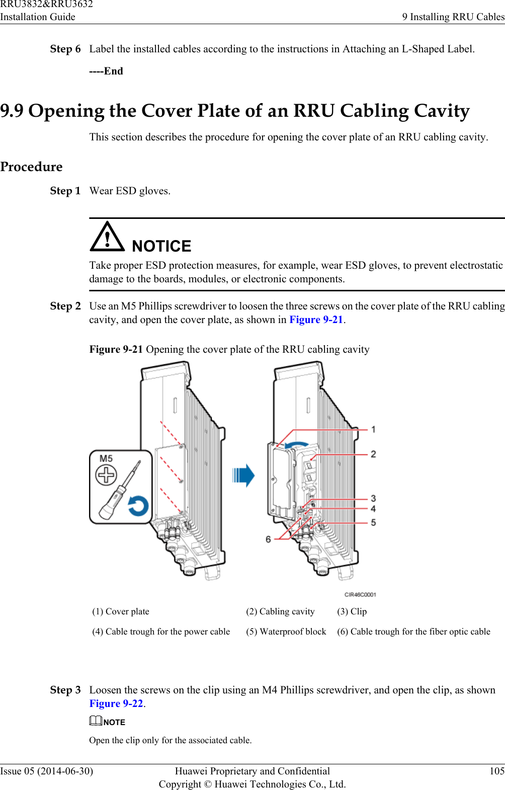
![Convention DescriptionItalic Command arguments are in italics.[ ] Items (keywords or arguments) in brackets [ ] are optional.{ x | y | ... } Optional items are grouped in braces and separated byvertical bars. One item is selected.[ x | y | ... ] Optional items are grouped in brackets and separated byvertical bars. One item is selected or no item is selected.{ x | y | ... }*Optional items are grouped in braces and separated byvertical bars. A minimum of one item or a maximum of allitems can be selected.[ x | y | ... ]*Optional items are grouped in brackets and separated byvertical bars. Several items or no item can be selected. GUI ConventionsThe GUI conventions that may be found in this document are defined as follows.Convention DescriptionBoldface Buttons, menus, parameters, tabs, window, and dialog titlesare in boldface. For example, click OK.>Multi-level menus are in boldface and separated by the ">"signs. For example, choose File > Create > Folder. Keyboard OperationsThe keyboard operations that may be found in this document are defined as follows.Format DescriptionKey Press the key. For example, press Enter and press Tab.Key 1+Key 2 Press the keys concurrently. For example, pressing Ctrl+Alt+A means the three keys should be pressed concurrently.Key 1, Key 2 Press the keys in turn. For example, pressing Alt, A meansthe two keys should be pressed in turn. Mouse OperationsThe mouse operations that may be found in this document are defined as follows.RRU3832&RRU3632Installation Guide About This DocumentIssue 05 (2014-06-30) Huawei Proprietary and ConfidentialCopyright © Huawei Technologies Co., Ltd.v](https://usermanual.wiki/Huawei-Technologies/RRU3832.User-Manual-III/User-Guide-2397836-Page-6.png)
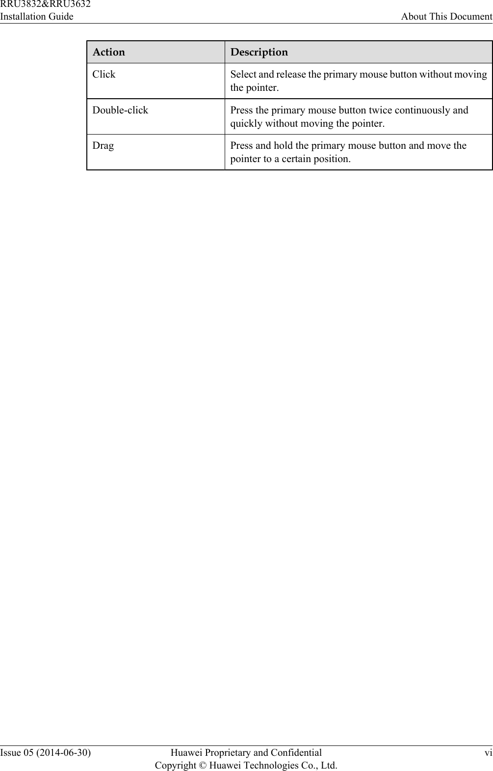

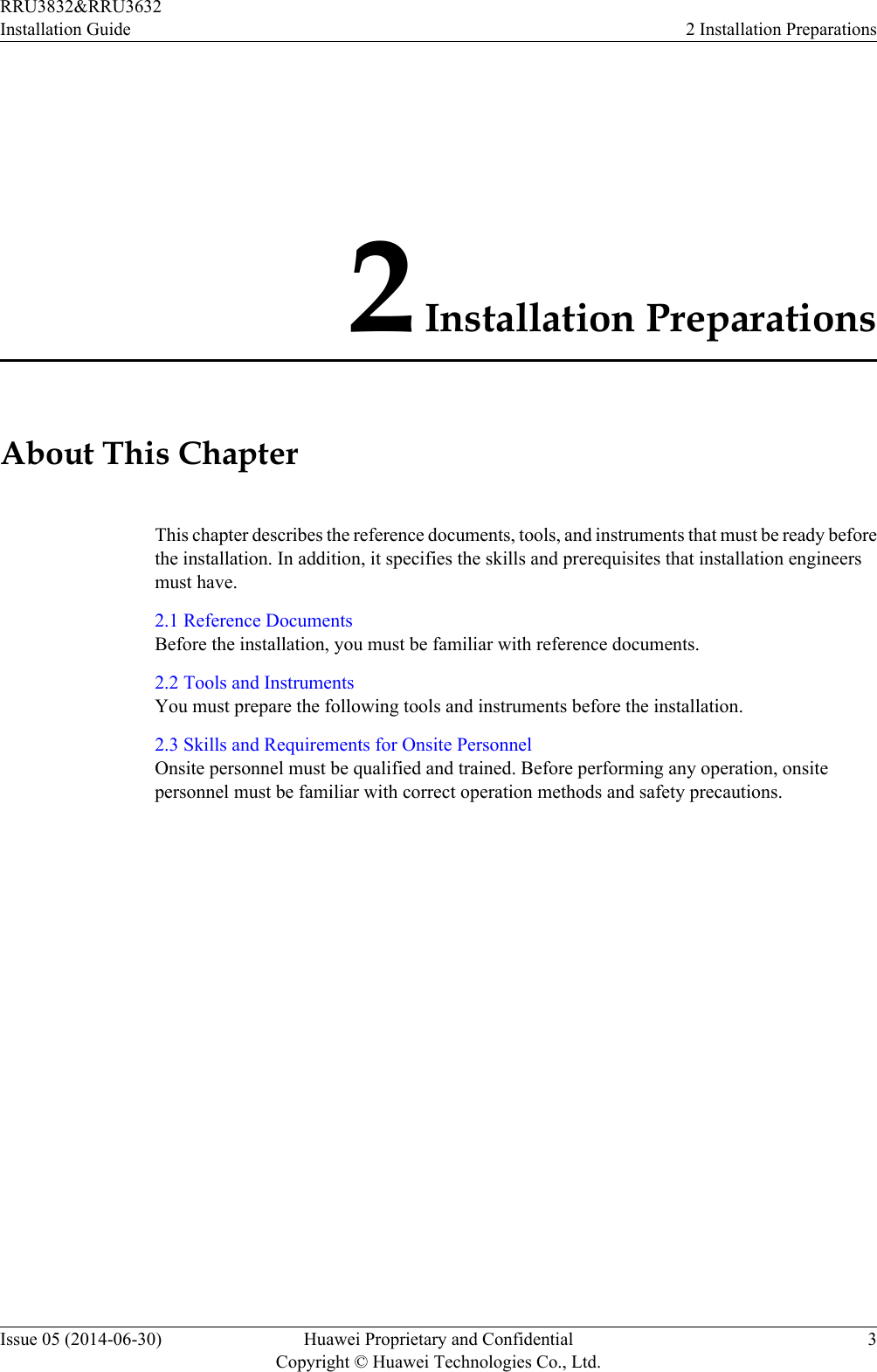
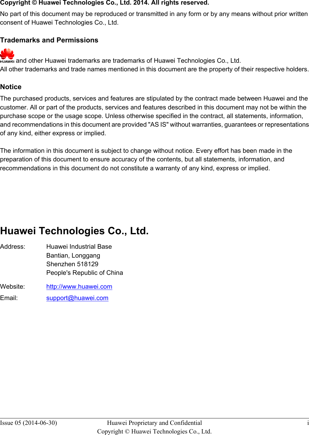
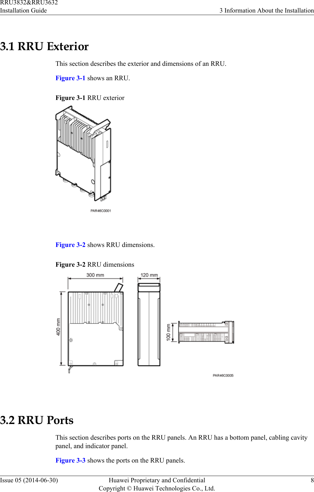
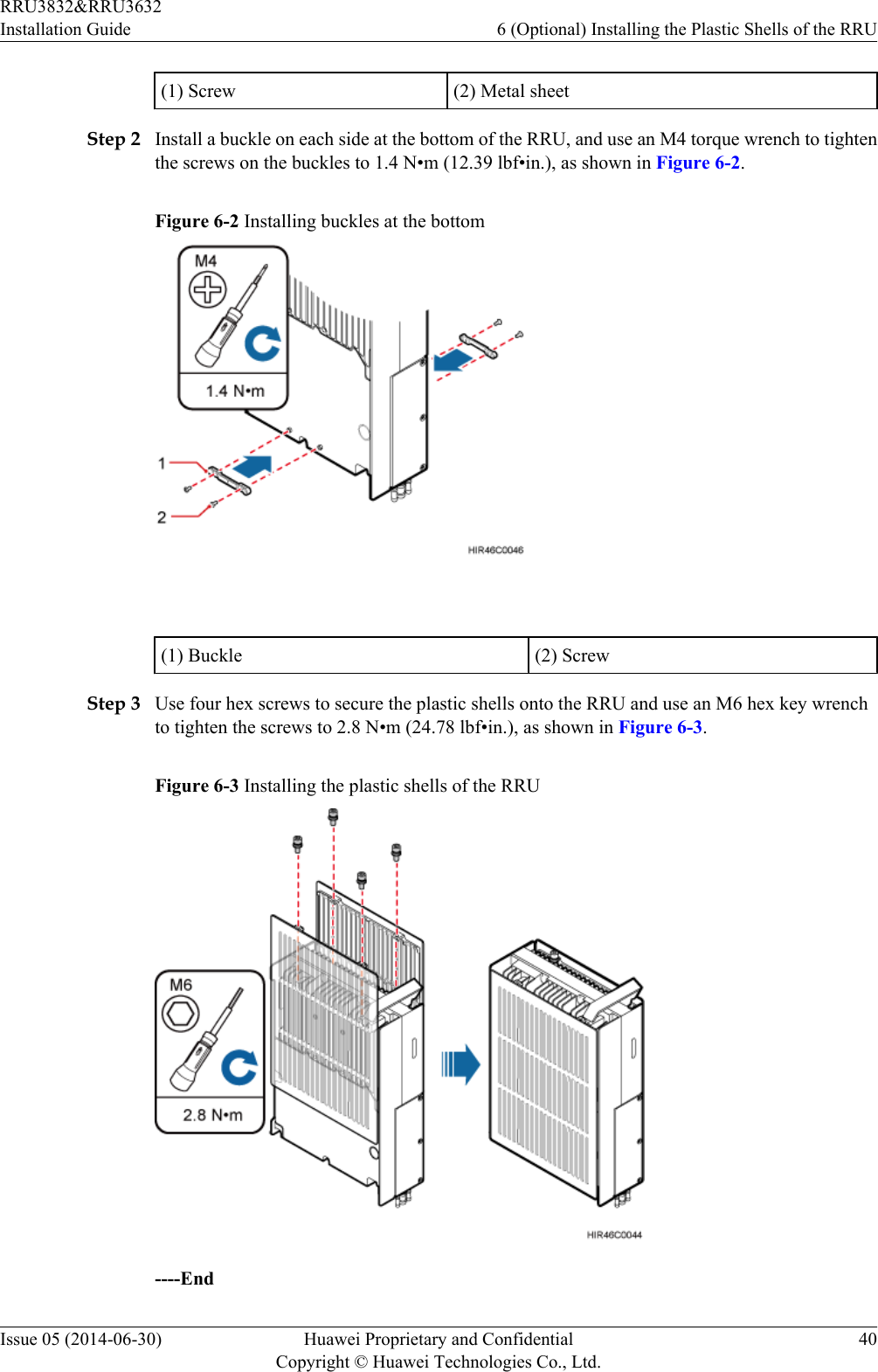
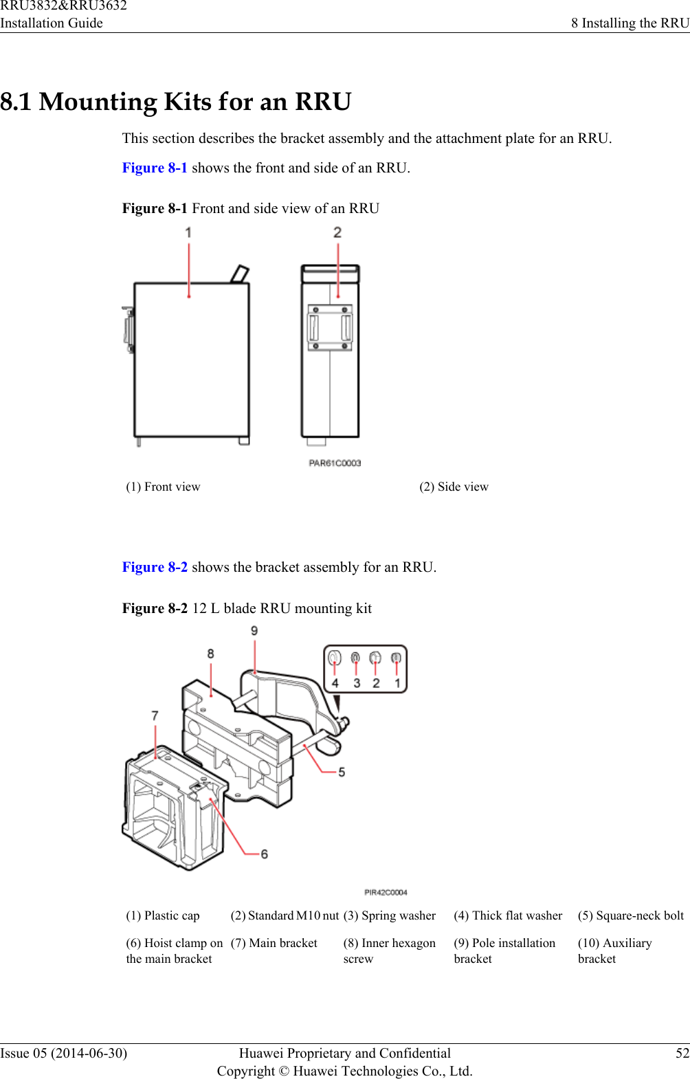
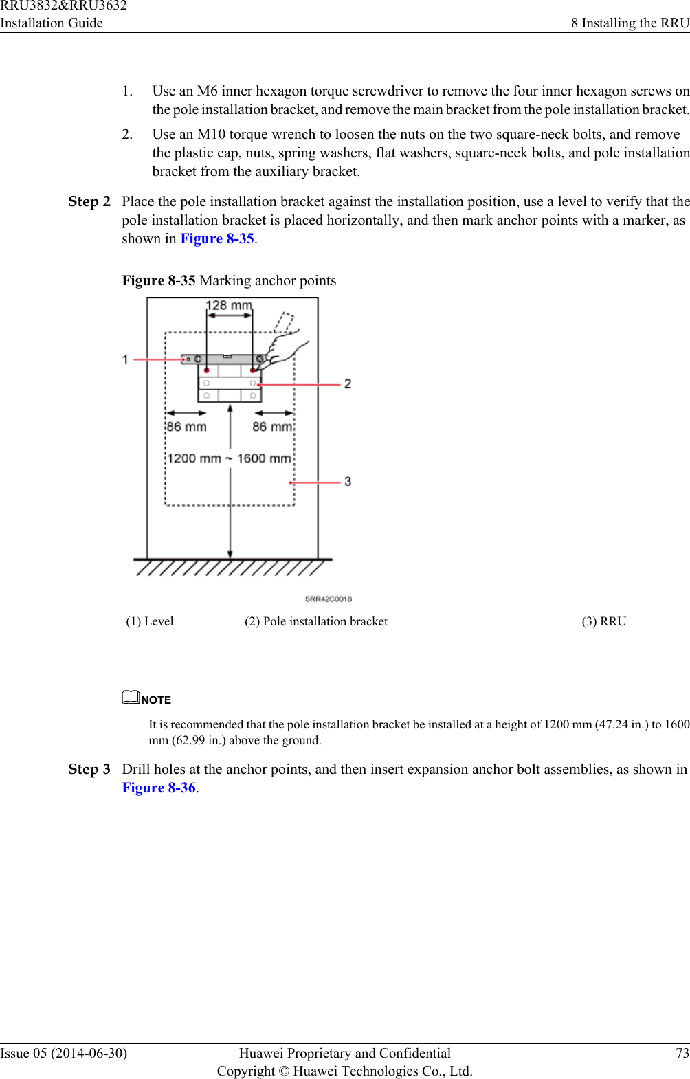
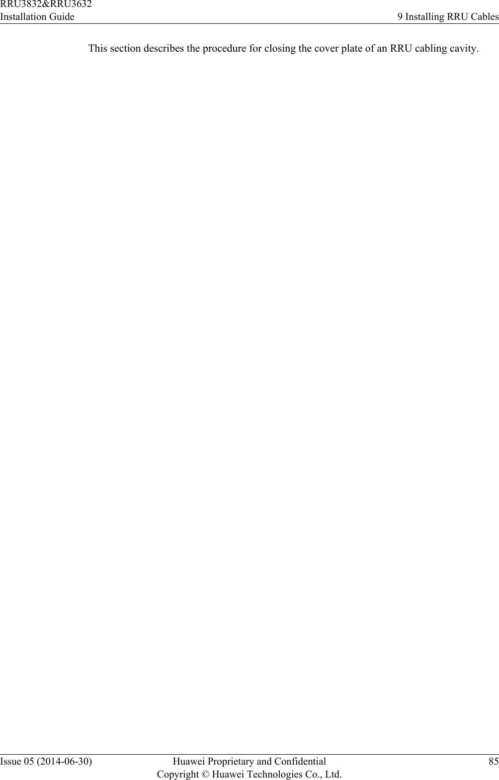
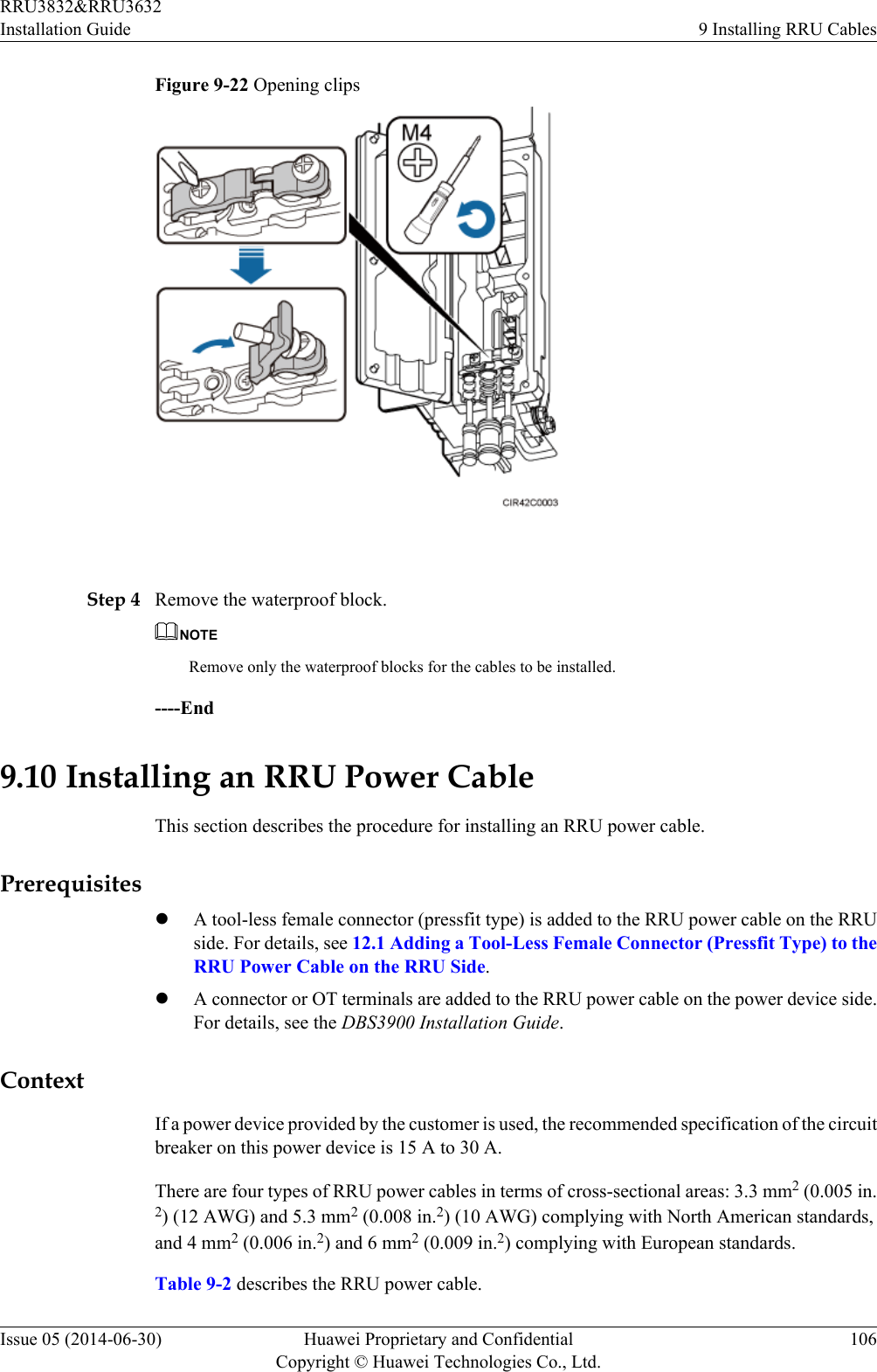
![Utility knife Cable cutter Adjustable wrench (size ≥ 32mm [1.26 in.])Torque wrenchSize: 16 mm (0.63 in.) and 32mm (1.26 in.)Combination wrenchSize: 16 mm (0.63 in.) and 32mm (1.26 in.)Level Torque screwdriver5 mm5 mm(M3 to M6)(M3 to M6)Torque socketMultimeter Marker (diameter ≤ 10 mm[0.39 in.])Measuring tapeInner hexagon wrench5 mmFixed pulley Lifting slingHydraulic pliers - - RRU3832&RRU3632Installation Guide 2 Installation PreparationsIssue 05 (2014-06-30) Huawei Proprietary and ConfidentialCopyright © Huawei Technologies Co., Ltd.5](https://usermanual.wiki/Huawei-Technologies/RRU3832.User-Manual-III/User-Guide-2397836-Page-14.png)
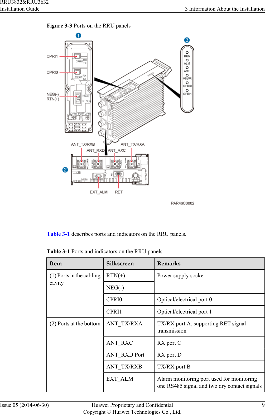
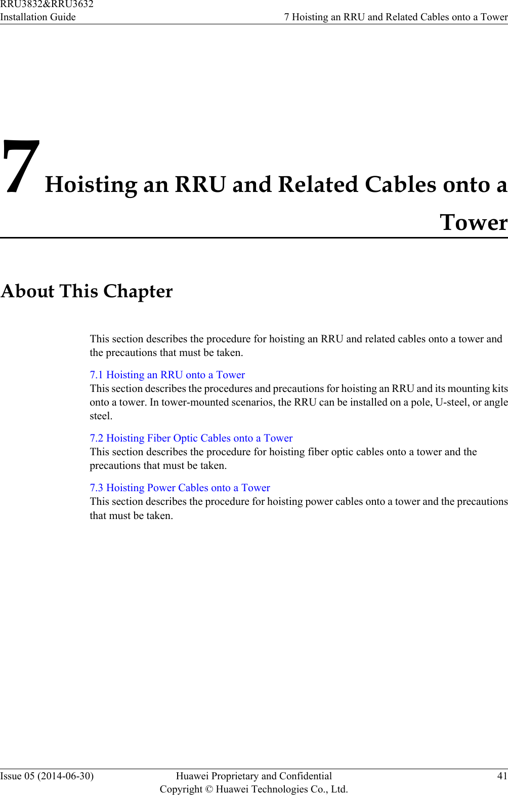
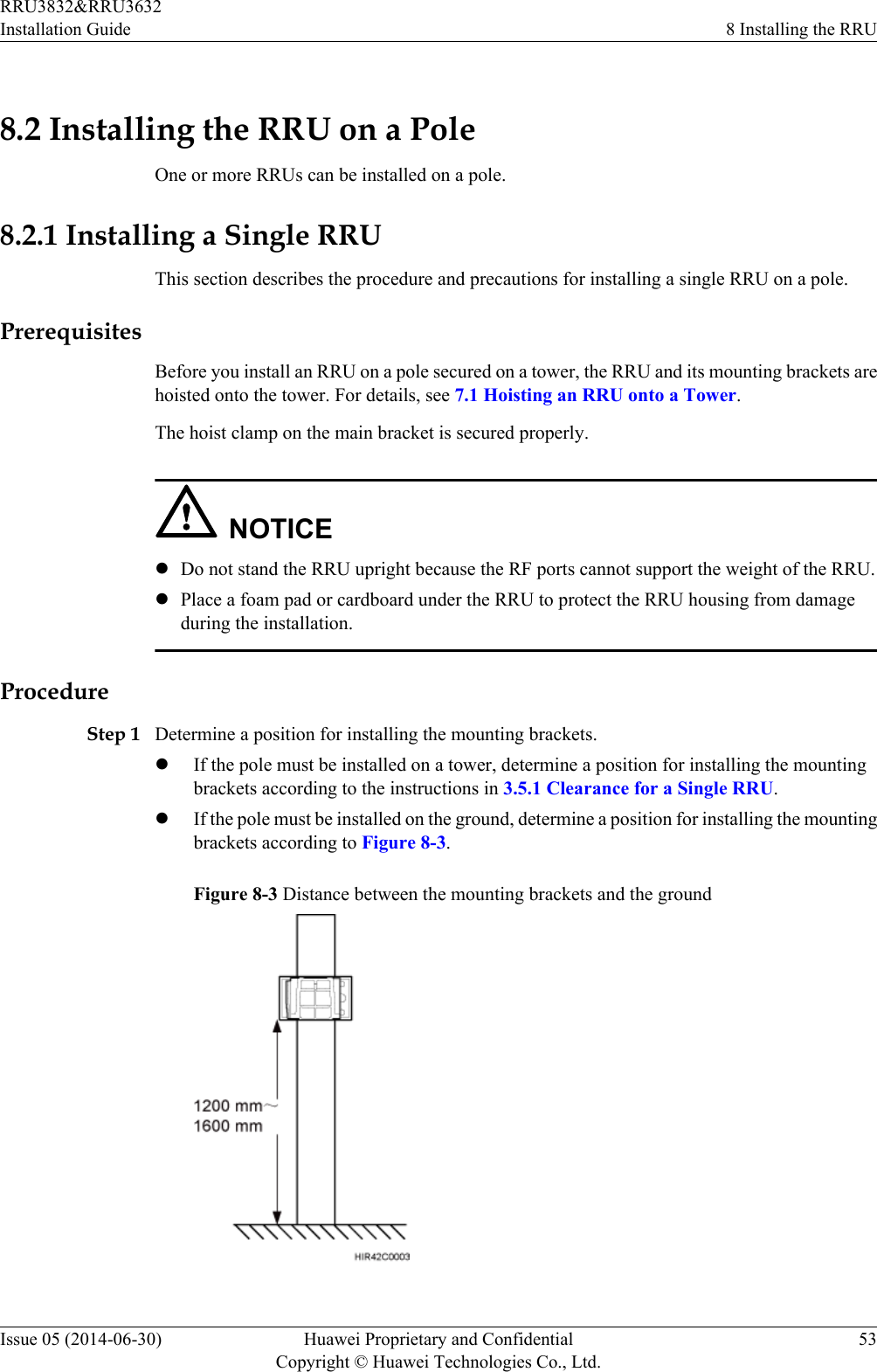

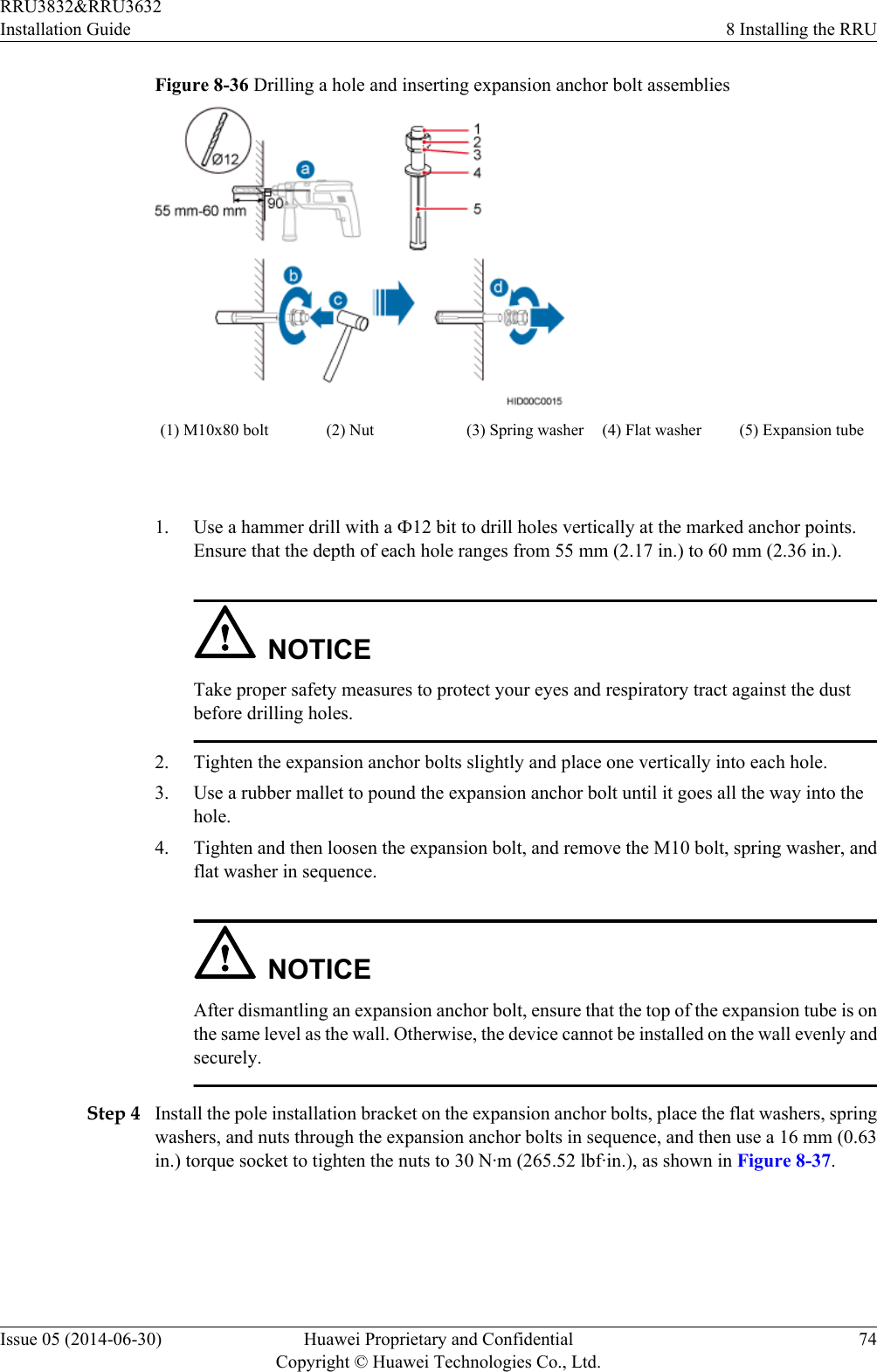
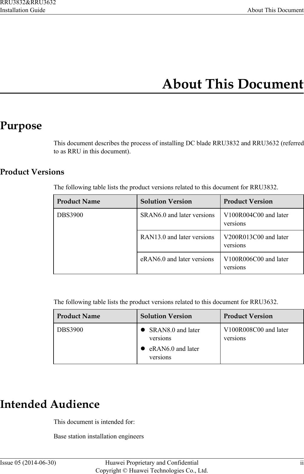
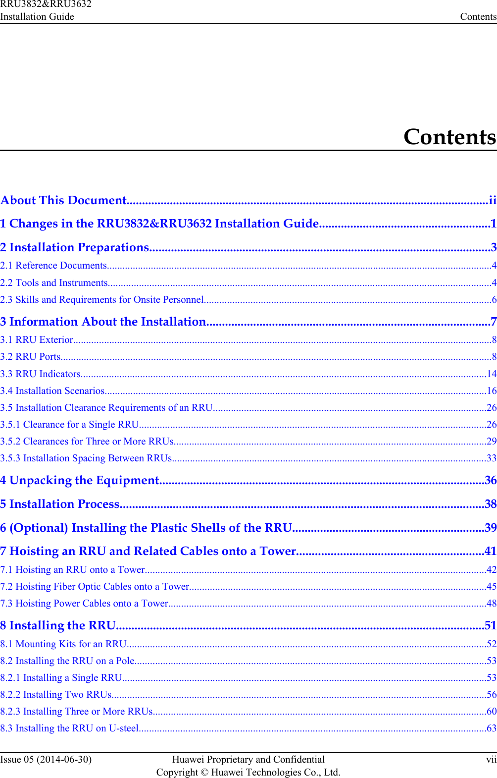
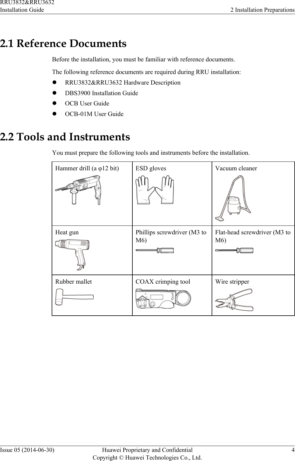
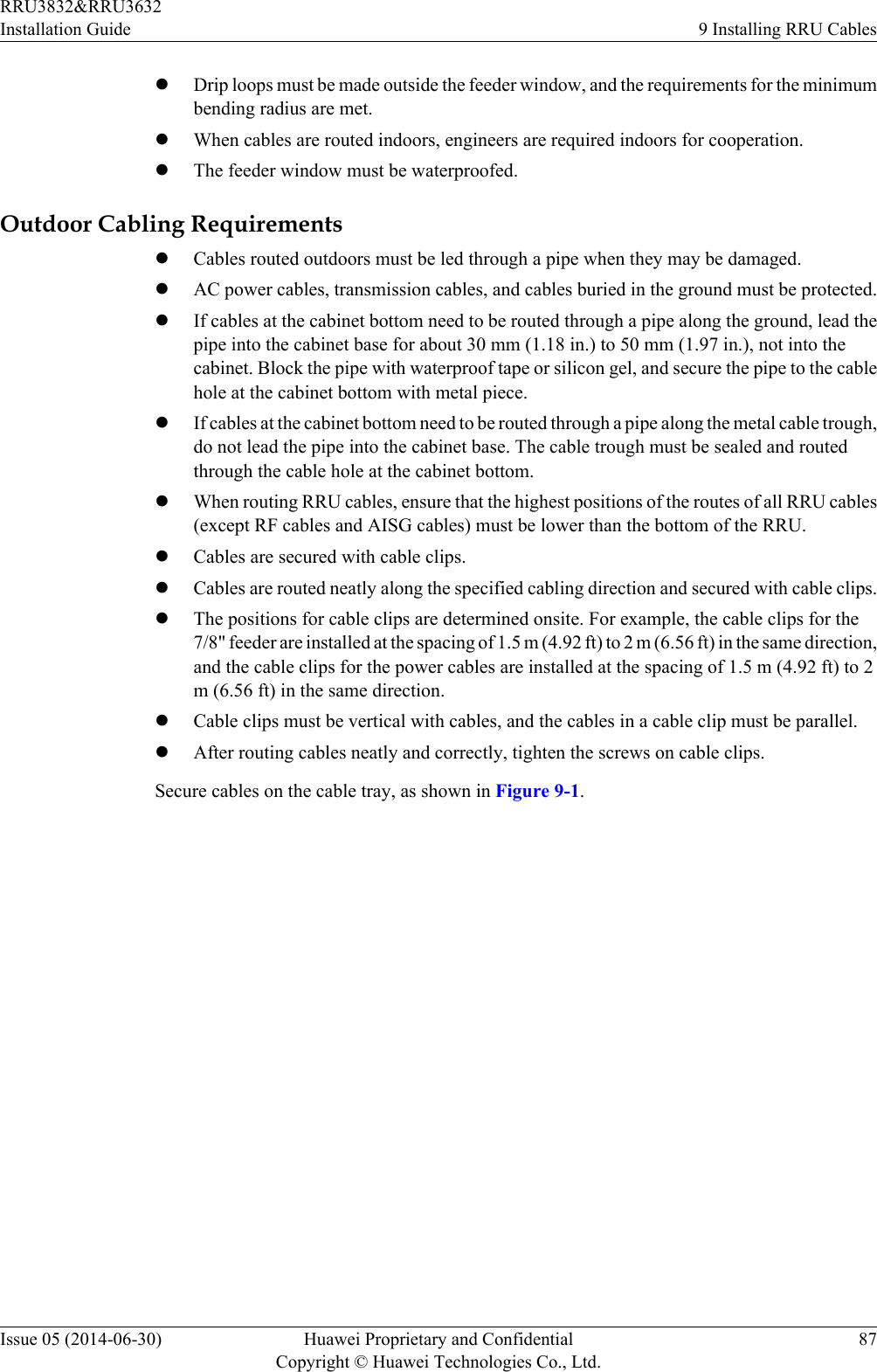
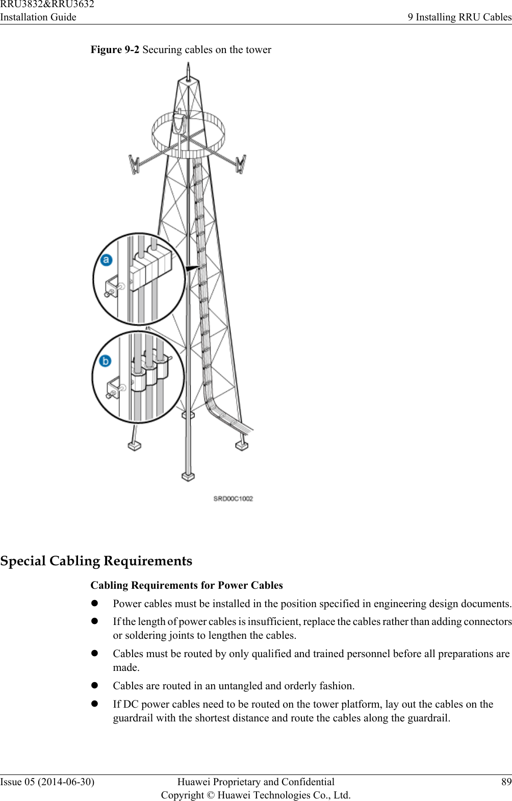
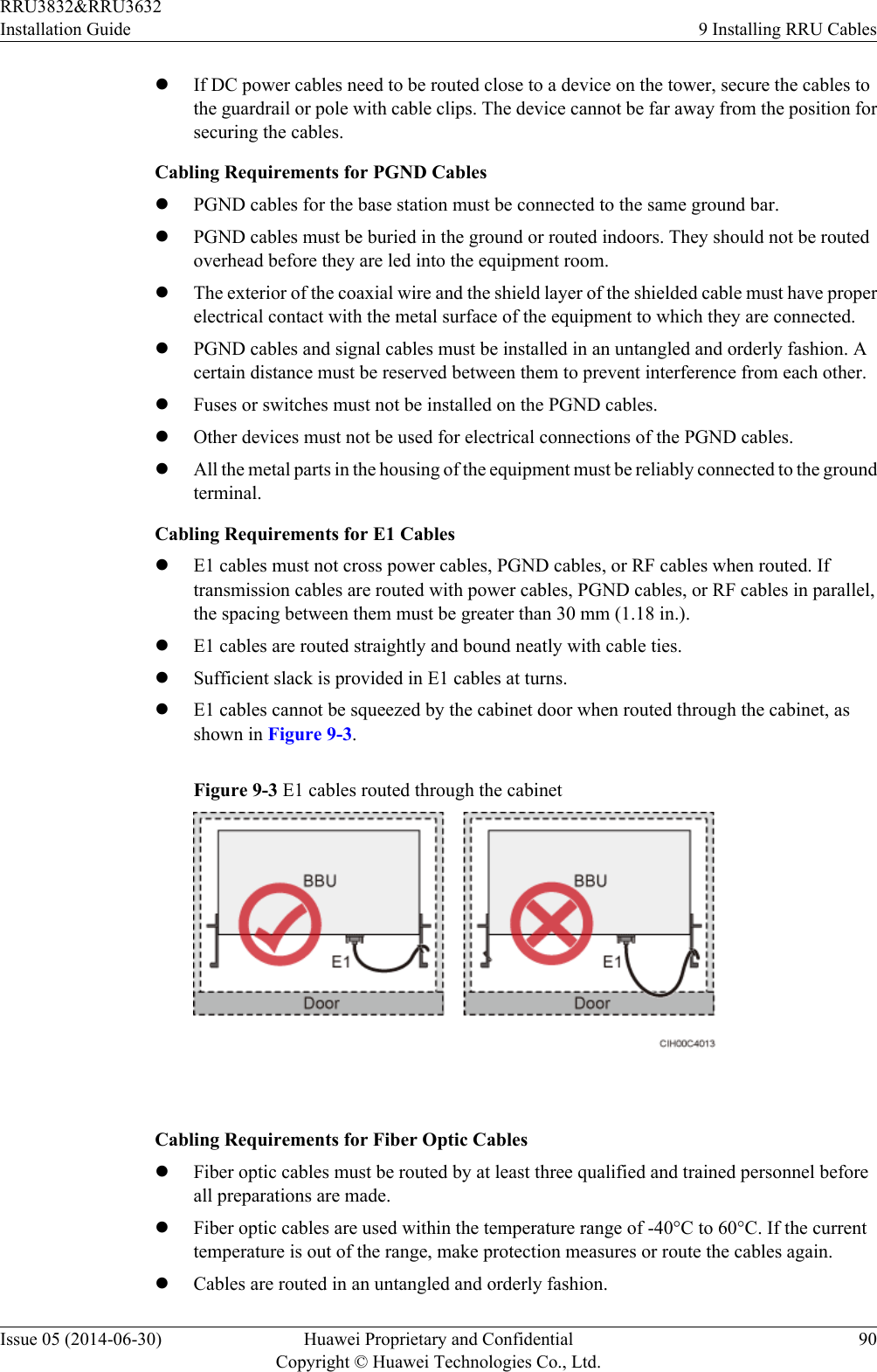
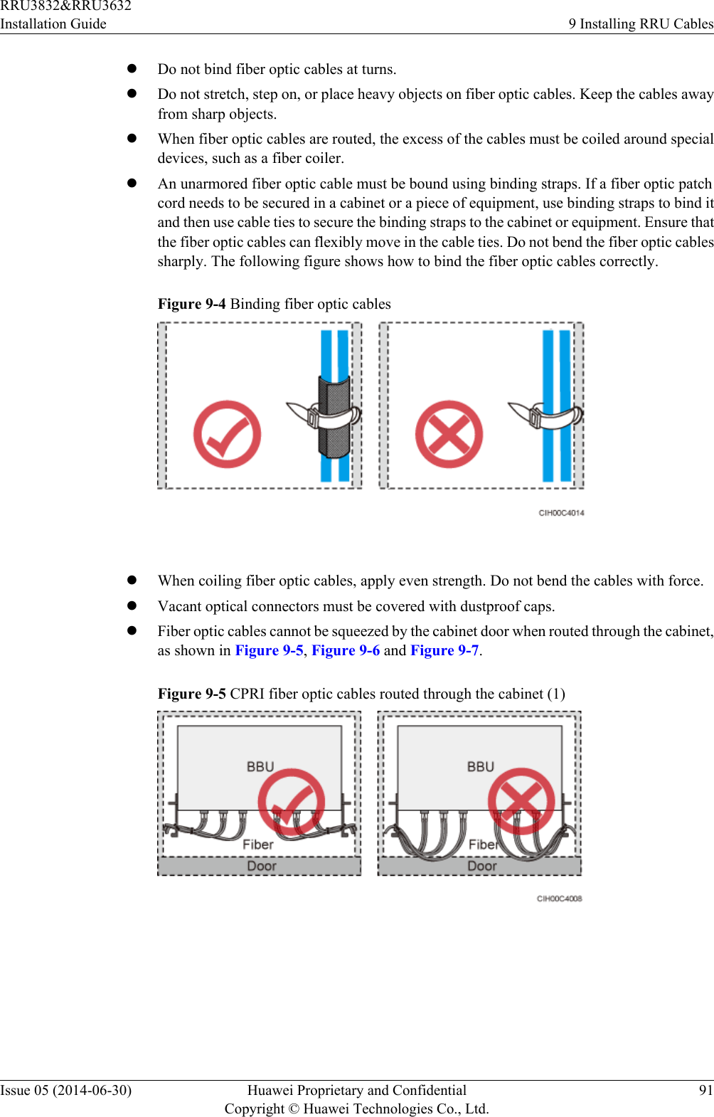
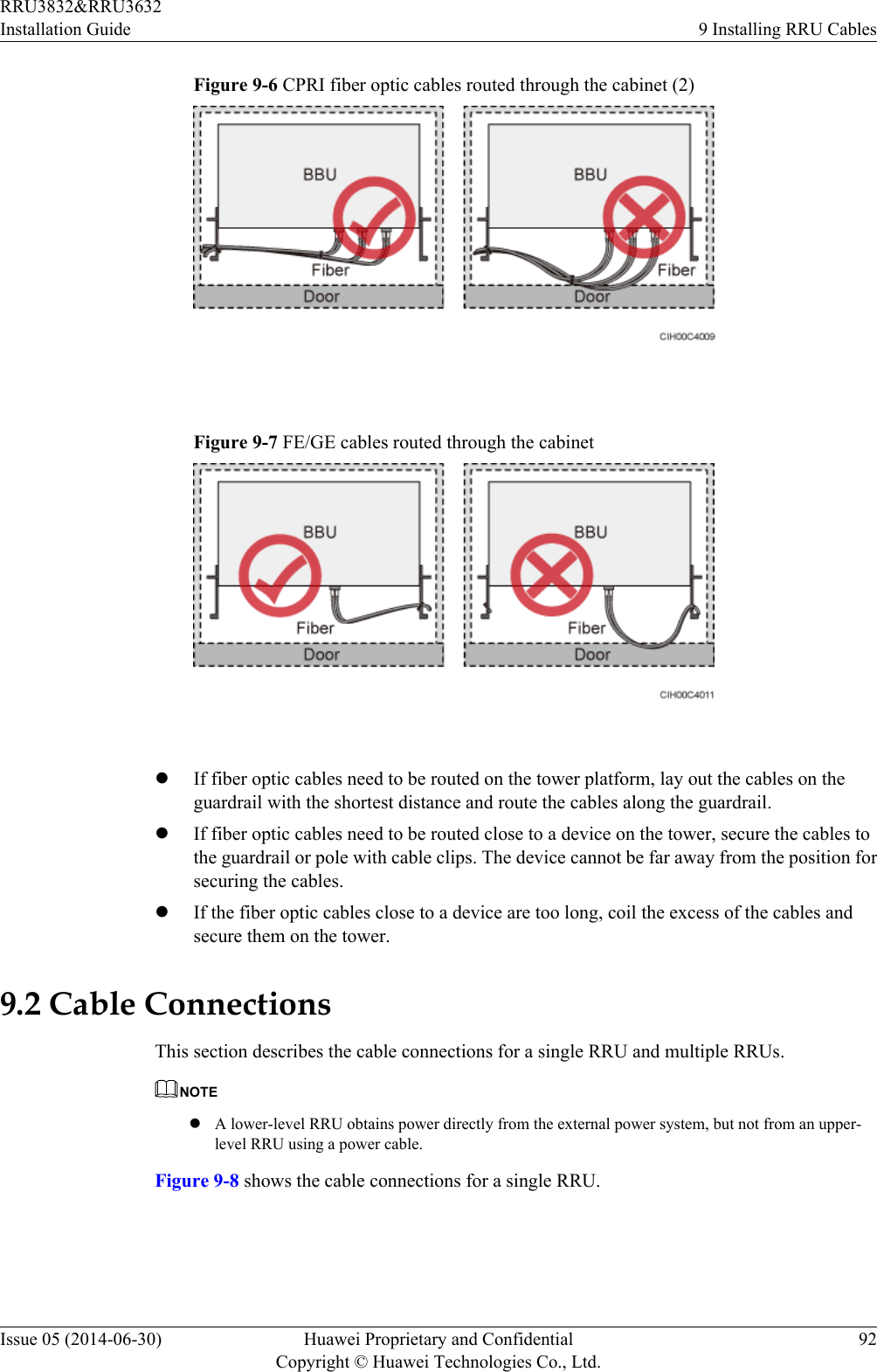
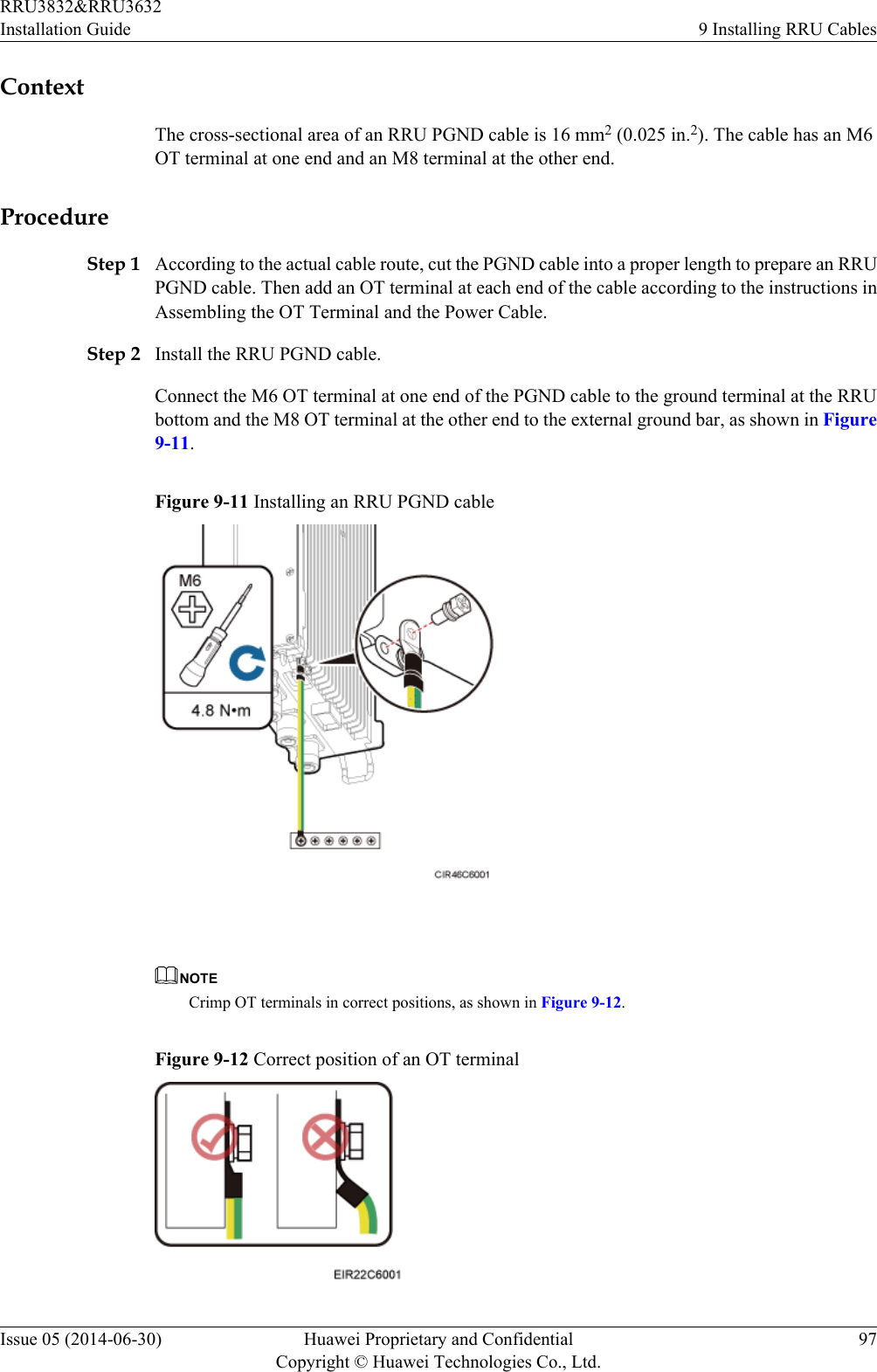
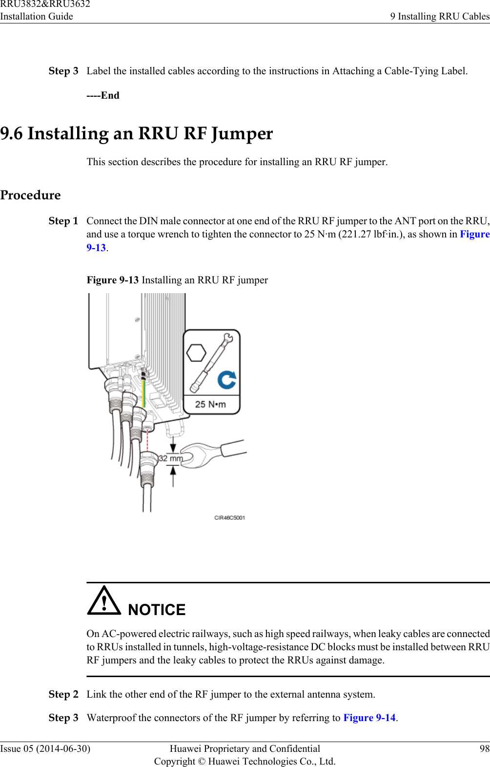
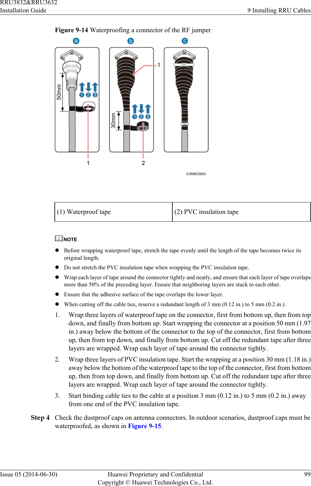
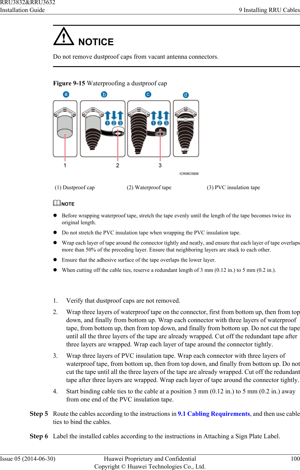
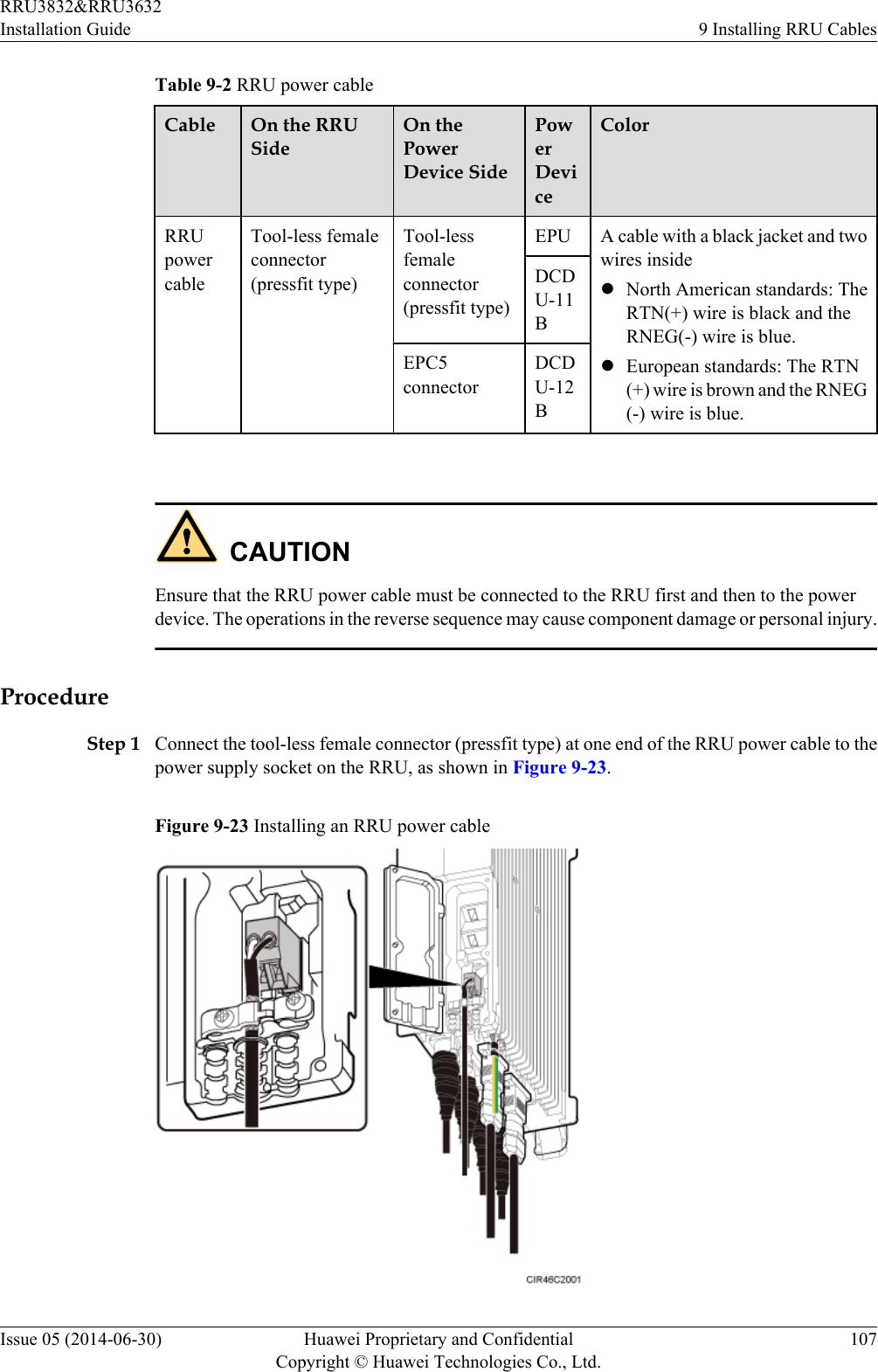
![9.1 Cabling RequirementsCables must be routed according to the specified cabling requirements to prevent signalinterference.NOTEIf a cable listed below is not required, skip the routing requirements of the cable.General Cabling RequirementsRequirements for Bending RadiuslThe bending radius of the 7/8'' feeder must be more than 250 mm (9.84 in.), and the bendingradius of the 5/4'' feeder must be more than 380 mm (14.96 in.).lThe bending radius of the 1/4'' jumper must be more than 35 mm (1.38 in.). The bendingradius of the super-flexible 1/2'' jumper must be more than 50 mm (1.97 in.), and the bendingradius of the ordinary 1/2'' jumper must be more than 127 mm (5 in.).lThe bending radius of the power cable or PGND cable must be at least three times thediameter of the cable.lThe bending radius of a fiber optic cable is at least 20 times the diameter of the fiber opticcable, and the minimum bending radius of the breakout cable at each end of the fiber opticcable is 30 mm (1.18 in.).lThe bending radius of the E1/T1 cable must be at least three times the diameter of the cable.lThe bending radius of the signal cable must be at least five times the diameter of the cable.Requirements for Cable BindinglThe same types of cable must be bound together.lDifferent types of cable must be separately routed with the minimum spacing of 30 mm(1.18 in.) and cannot be entangled.lThe cables must be bound tightly and neatly. The sheaths of the cables must not be damaged.lCable ties are installed in the same direction, and those at the same horizontal line must bein a straight line.lThe excess of indoor cable ties is trimmed off, and the excess of outdoor cable ties allowsabout 5 mm (0.2 in.), without remaining rough edges.lLabels or nameplates must be attached to both ends, joints, or turns of cables after they areinstalled.Security RequirementslCables should be placed away from sharp objects or wall burrs. If these positions areinevitable, protect the cables with protection pipes.lCables must be routed away from heat sources, or heat-insulation materials are addedbetween cables and heat sources.lSufficient slack (recommended for about 0.1 m [0.33 ft]) is provided in cables at turns orthe position close to a device, facilitating cable and device maintenance.Indoor Cabling RequirementslCables are routed indoors through the feeder window.RRU3832&RRU3632Installation Guide 9 Installing RRU CablesIssue 05 (2014-06-30) Huawei Proprietary and ConfidentialCopyright © Huawei Technologies Co., Ltd.86](https://usermanual.wiki/Huawei-Technologies/RRU3832.User-Manual-III/User-Guide-2397836-Page-95.png)
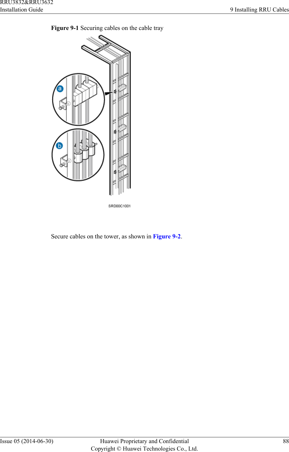
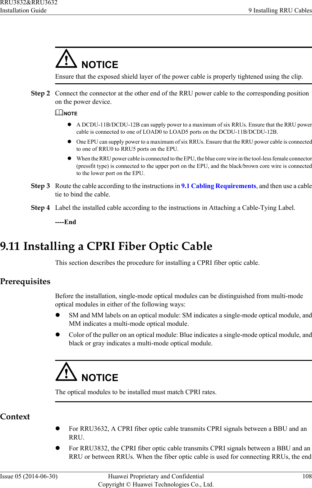
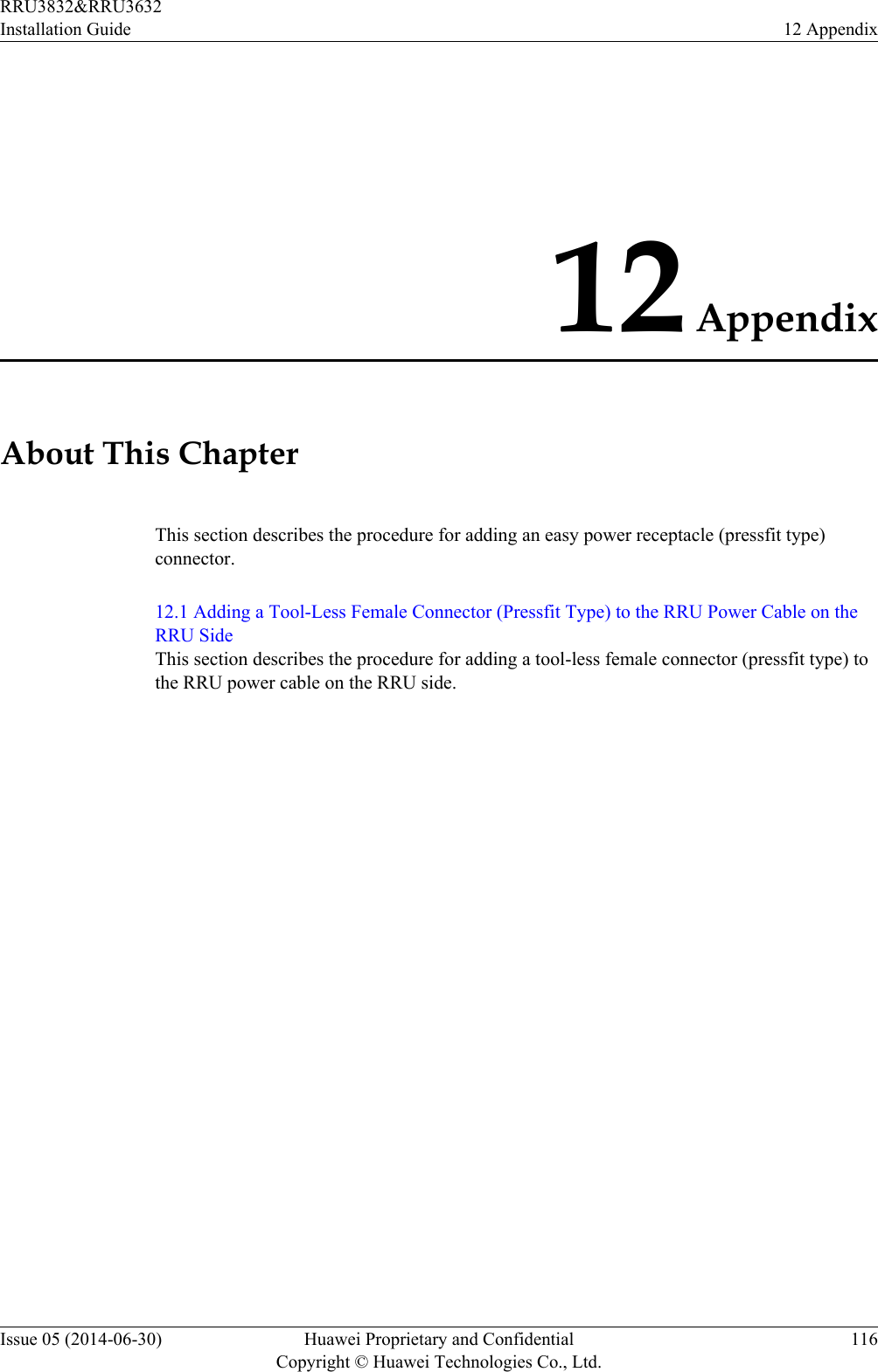
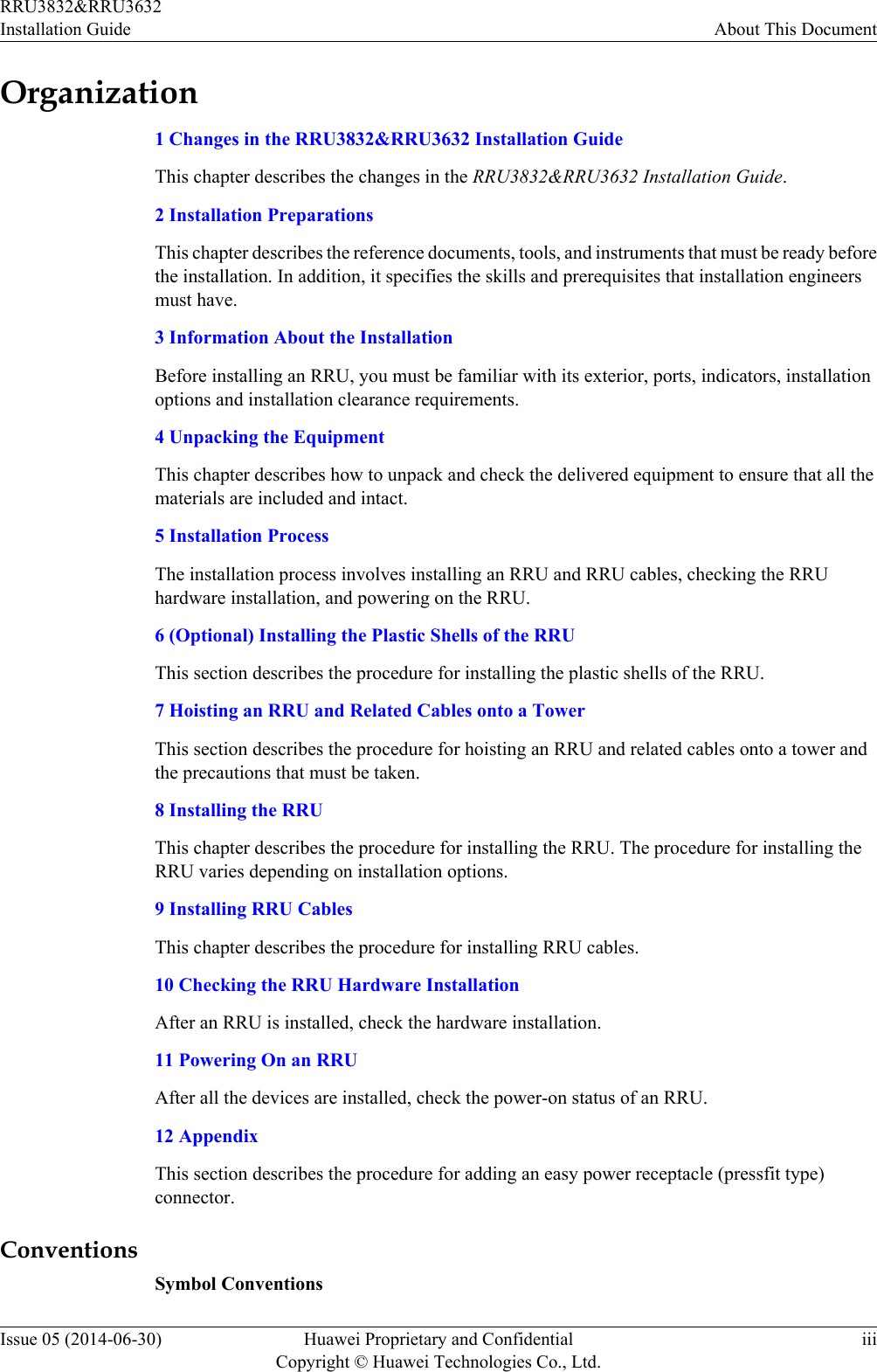
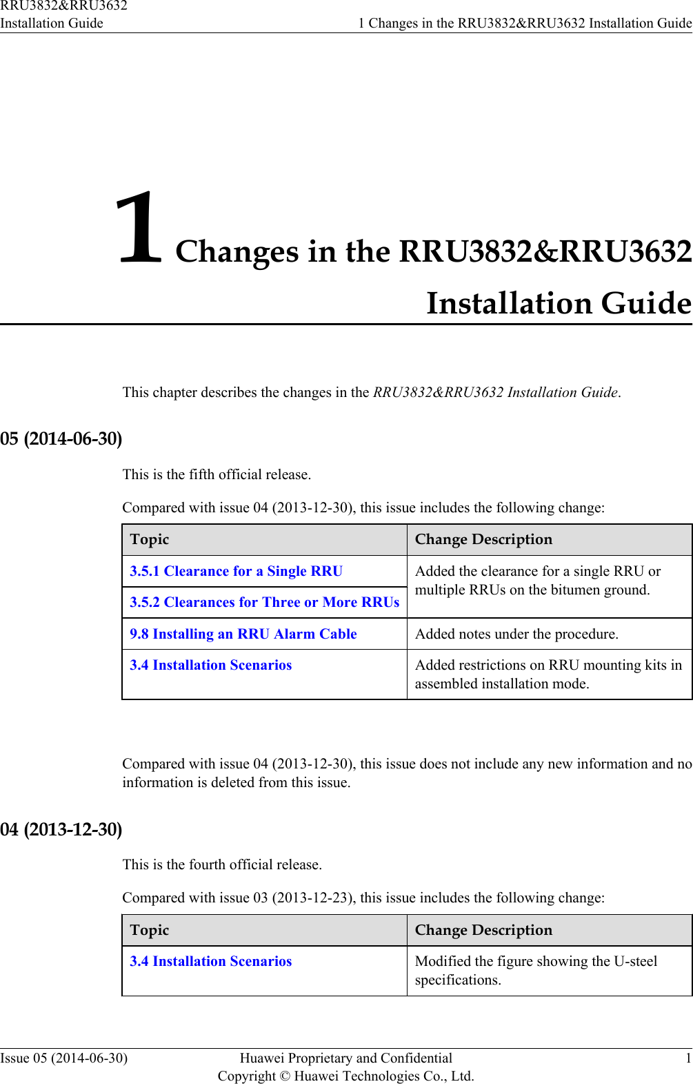
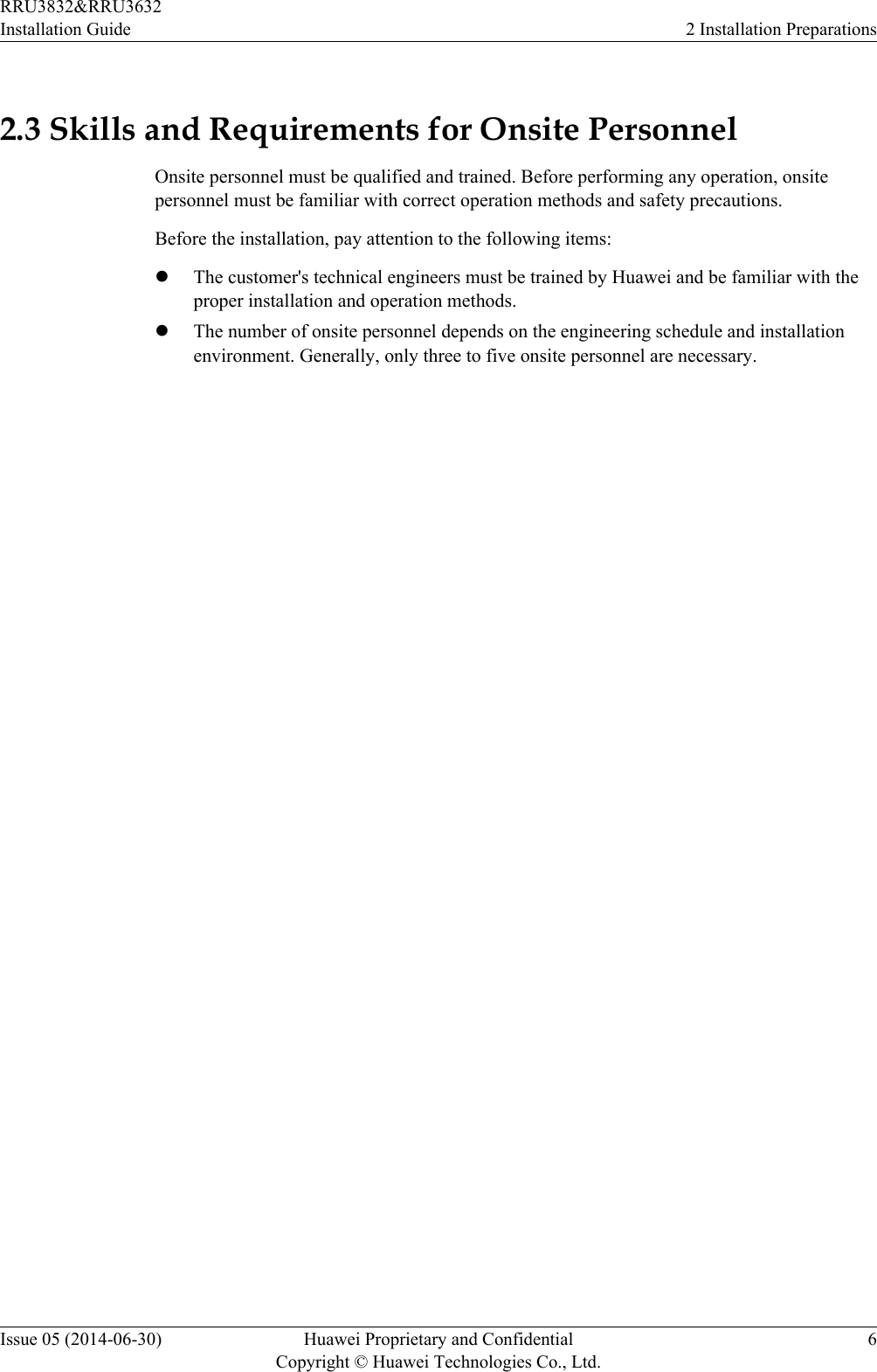
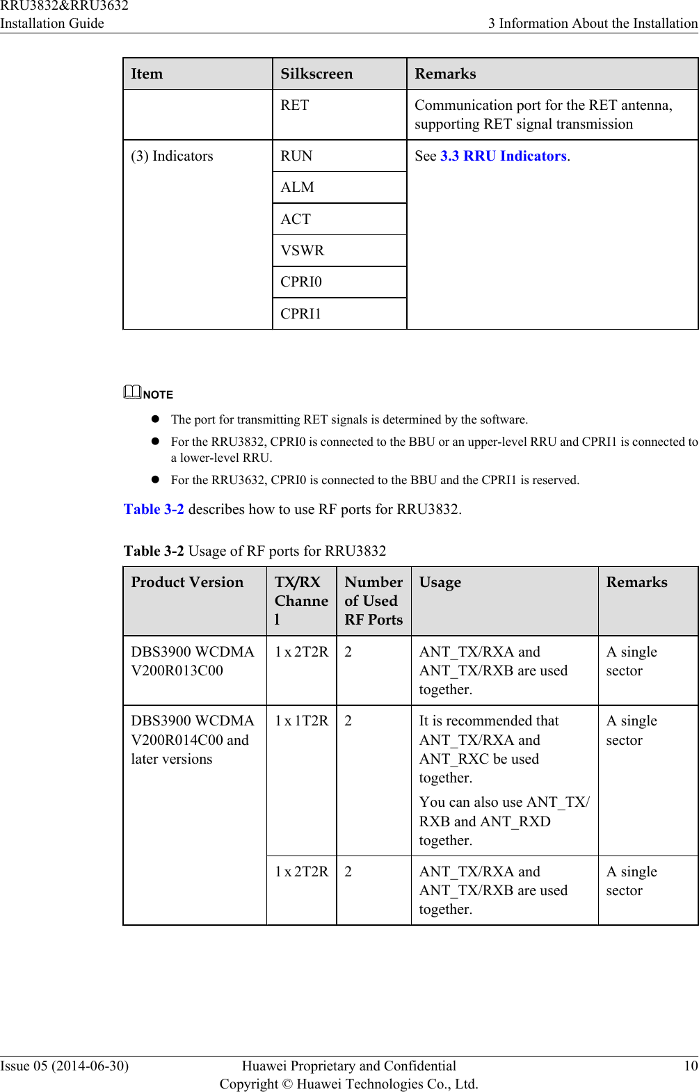
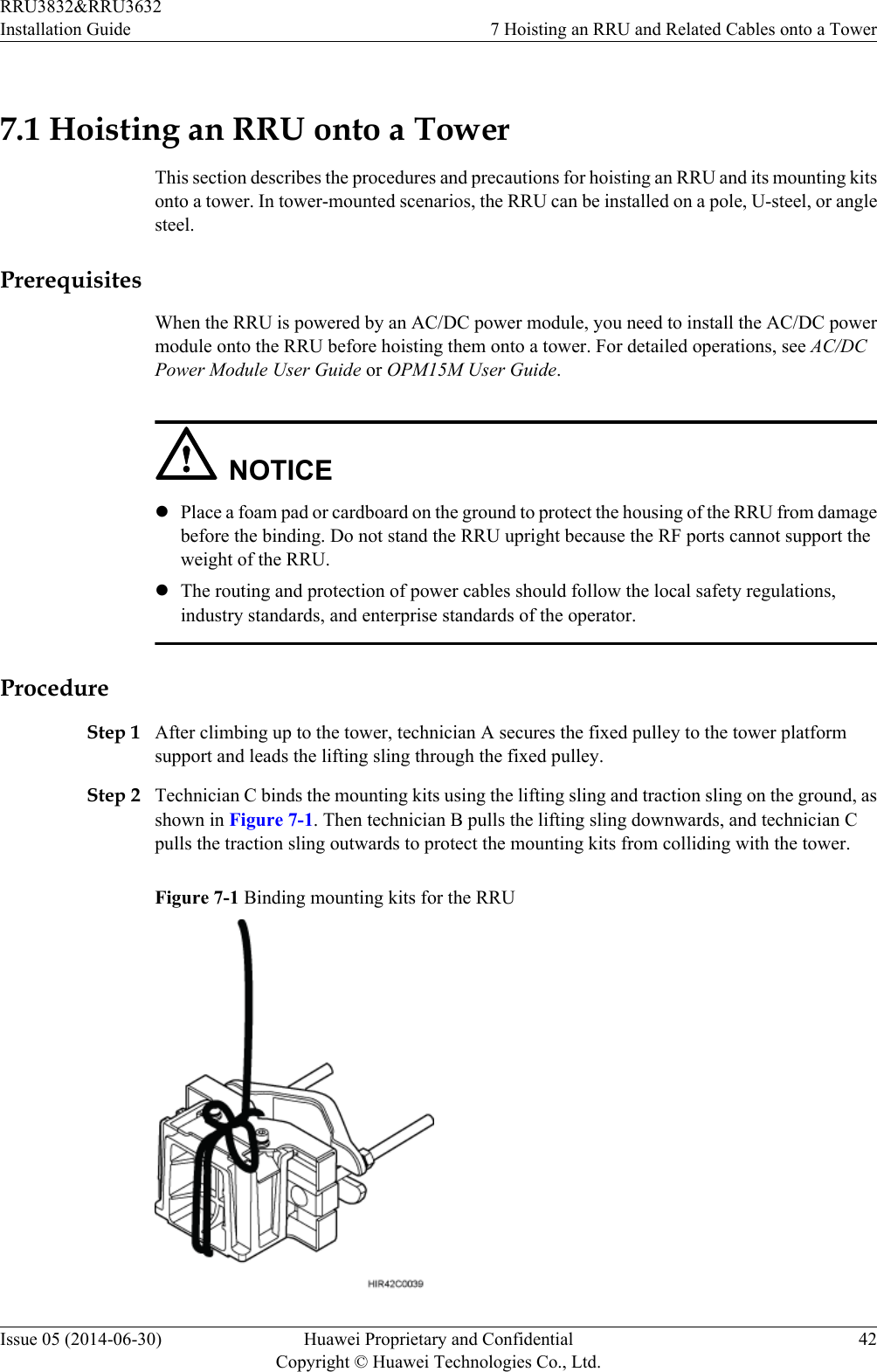
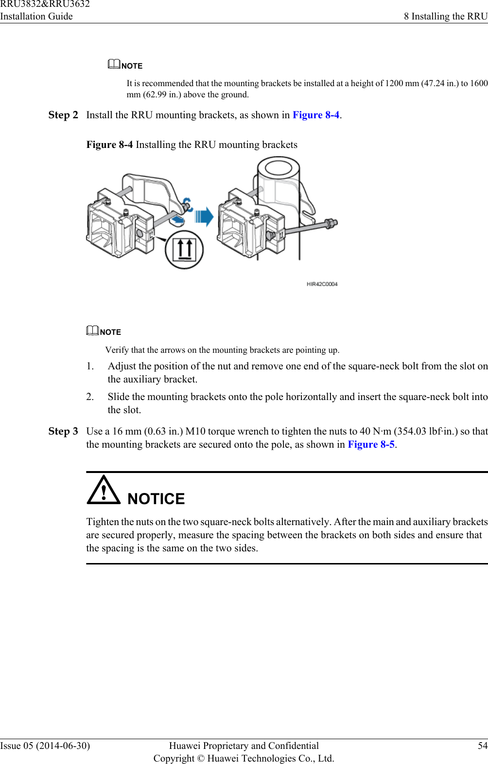
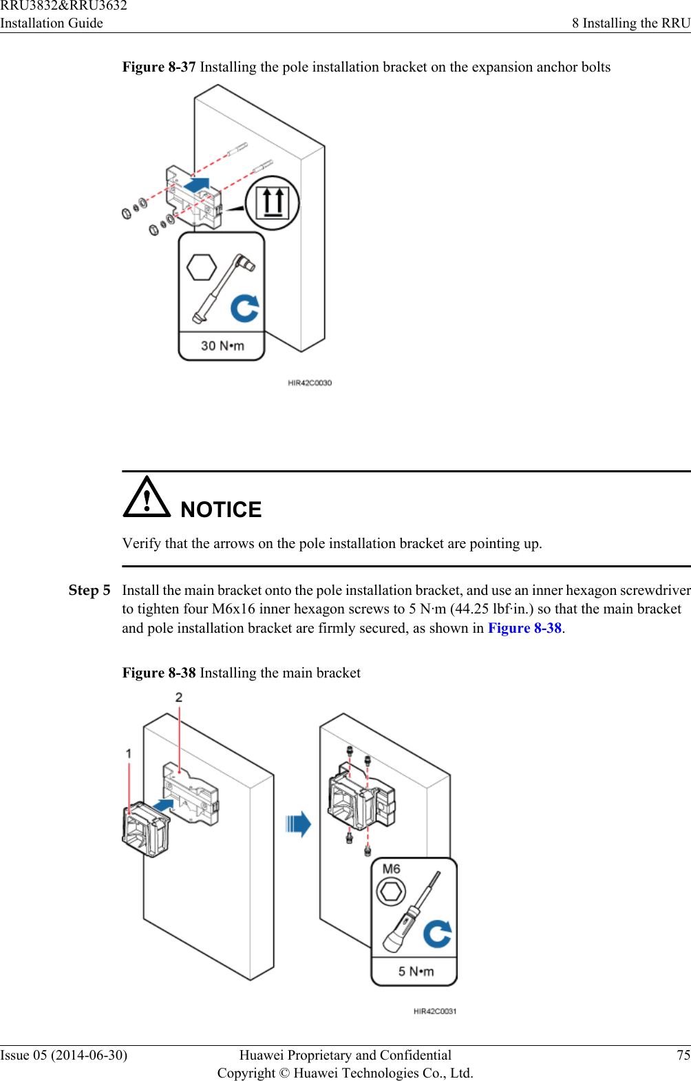
![Figure 12-8 Stripping the sheath off the power cable NOTICEEach core wire is exposed outside the tool-less female connector (pressfit type) for 1.5 mm(0.059 [in.]), as shown in Figure 12-9.Figure 12-9 Inserting core wires into the tool-less female connector (pressfit type)----EndRRU3832&RRU3632Installation Guide 12 AppendixIssue 05 (2014-06-30) Huawei Proprietary and ConfidentialCopyright © Huawei Technologies Co., Ltd.120](https://usermanual.wiki/Huawei-Technologies/RRU3832.User-Manual-III/User-Guide-2397836-Page-129.png)