Huawei Technologies RRU3908 Remote Radio Unit of Multi-Mode Distributed Base Station User Manual Hardware Maintenance Guide
Huawei Technologies Co.,Ltd Remote Radio Unit of Multi-Mode Distributed Base Station Hardware Maintenance Guide
Maintenance Guide

RRU3908 V2
V100R003
Hardware Maintenance Guide
Issue 01
Date 2010-04-10
Huawei Proprietary and Confidential
Copyright © Huawei Technologies Co., Ltd.

Huawei Technologies Co., Ltd. provides customers with comprehensive technical support and service. For any
assistance, please contact our local office or company headquarters.
Huawei Technologies Co., Ltd.
Address: Huawei Industrial Base
Bantian, Longgang
Shenzhen 518129
People's Republic of China
Website: http://www.huawei.com
Email: support@huawei.com
Copyright © Huawei Technologies Co., Ltd. 2010. All rights reserved.
No part of this document may be reproduced or transmitted in any form or by any means without prior written
consent of Huawei Technologies Co., Ltd.
Trademarks and Permissions
and other Huawei trademarks are the property of Huawei Technologies Co., Ltd.
All other trademarks and trade names mentioned in this document are the property of their respective holders.
Notice
The purchased products, services and features are stipulated by the contract made between Huawei and the
customer. All or part of the products, services and features described in this document may not be within the
purchase scope or the usage scope. Unless otherwise specified in the contract, all statements, information,
and recommendations in this document are provided "AS IS" without warranties, guarantees or representations
of any kind, either express or implied.
The information in this document is subject to change without notice. Every effort has been made in the
preparation of this document to ensure accuracy of the contents, but all statements, information, and
recommendations in this document do not constitute the warranty of any kind, express or implied.
Huawei Proprietary and Confidential
Copyright © Huawei Technologies Co., Ltd.

Contents
About This Document.....................................................................................................................1
1 Changes in the RRU3908 V2 Hardware Maintenance Guide............................................1-1
2 Maintenance Items for the RRU..............................................................................................2-1
3 Powering On and Powering Off the RRU.............................................................................3-1
3.1 Powering On the RRU.....................................................................................................................................3-2
3.2 Powering Off the RRU....................................................................................................................................3-3
4 Replacing the RRU.....................................................................................................................4-1
5 Replacing the Optical Module.................................................................................................5-1
RRU3908 V2
Hardware Maintenance Guide Contents
Issue 01 (2010-04-10) Huawei Proprietary and Confidential
Copyright © Huawei Technologies Co., Ltd.
i

Figures
Figure 4-1 Loosening the captive screws on the main bracket............................................................................4-2
Figure 4-2 Tightening the screws on the adapting piece......................................................................................4-2
Figure 4-3 Lifting the bottom of the RRU...........................................................................................................4-3
RRU3908 V2
Hardware Maintenance Guide Figures
Issue 01 (2010-04-10) Huawei Proprietary and Confidential
Copyright © Huawei Technologies Co., Ltd.
iii

About This Document
Purpose
This document describes the routine maintenance items for the RRU3908 hardware, such as
equipment maintenance and power-on and power-off operations. It also describes the procedures
for replacing components and modules.
Product Version
The following table lists the product version related to this document.
Product Name Product Version
RRU3908 V2 (hereinafter referred to as
RRU3908)
SRAN V100R003
eRAN V100R002C00
Intended Audience
This document is intended for:
lSystem engineers
lSite maintainers
Organization
1 Changes in the RRU3908 V2 Hardware Maintenance Guide
This chapter describes the changes in the RRU3908 V2 Hardware Maintenance Guide.
2 Maintenance Items for the RRU
The maintenance items for the RRU are equipment surface, equipment cleanliness, and LEDs.
3 Powering On and Powering Off the RRU
RRU3908 V2
Hardware Maintenance Guide About This Document
Issue 01 (2010-04-10) Huawei Proprietary and Confidential
Copyright © Huawei Technologies Co., Ltd.
1
This describes how to power on and power off the RRU. When powering on the RRU, you should
check the power supply voltage of the RRU and the status of the LEDs on the RRU. When
powering off the RRU, you can perform normal power-off or emergency power-off operation
based on field requirements.
4 Replacing the RRU
The RRU, a remote radio unit, forms a distributed BTS with the BBU.
5 Replacing the Optical Module
The optical module implements optical-electrical conversion, thus enabling optical transmission
between the RRU and other devices. You need to remove the optical cable before replacing the
optical module. Replacing the optical cable disrupts the transmission of CPRI signals.
Conventions
Symbol Conventions
The symbols that may be found in this document are defined as follows.
Symbol Description
Indicates a hazard with a high level of risk, which if not
avoided,will result in death or serious injury.
Indicates a hazard with a medium or low level of risk, which
if not avoided, could result in minor or moderate injury.
Indicates a potentially hazardous situation, which if not
avoided,could result in equipment damage, data loss,
performance degradation, or unexpected results.
Indicates a tip that may help you solve a problem or save
time.
Provides additional information to emphasize or supplement
important points of the main text.
General Conventions
The general conventions that may be found in this document are defined as follows.
Convention Description
Times New Roman Normal paragraphs are in Times New Roman.
Boldface Names of files, directories, folders, and users are in
boldface. For example, log in as user root.
Italic Book titles are in italics.
Courier New Examples of information displayed on the screen are in
Courier New.
About This Document
RRU3908 V2
Hardware Maintenance Guide
2 Huawei Proprietary and Confidential
Copyright © Huawei Technologies Co., Ltd.
Issue 01 (2010-04-10)
Command Conventions
The command conventions that may be found in this document are defined as follows.
Convention Description
Boldface The keywords of a command line are in boldface.
Italic Command arguments are in italics.
[ ] Items (keywords or arguments) in brackets [ ] are optional.
{ x | y | ... } Optional items are grouped in braces and separated by
vertical bars. One item is selected.
[ x | y | ... ] Optional items are grouped in brackets and separated by
vertical bars. One item is selected or no item is selected.
{ x | y | ... }*Optional items are grouped in braces and separated by
vertical bars. A minimum of one item or a maximum of all
items can be selected.
[ x | y | ... ]*Optional items are grouped in brackets and separated by
vertical bars. Several items or no item can be selected.
GUI Conventions
The GUI conventions that may be found in this document are defined as follows.
Convention Description
Boldface Buttons, menus, parameters, tabs, window, and dialog titles
are in boldface. For example, click OK.
>Multi-level menus are in boldface and separated by the ">"
signs. For example, choose File > Create > Folder.
Keyboard Operations
The keyboard operations that may be found in this document are defined as follows.
Format Description
Key Press the key. For example, press Enter and press Tab.
Key 1+Key 2 Press the keys concurrently. For example, pressing Ctrl+Alt
+A means the three keys should be pressed concurrently.
Key 1, Key 2 Press the keys in turn. For example, pressing Alt, A means
the two keys should be pressed in turn.
RRU3908 V2
Hardware Maintenance Guide About This Document
Issue 01 (2010-04-10) Huawei Proprietary and Confidential
Copyright © Huawei Technologies Co., Ltd.
3

Mouse Operations
The mouse operations that may be found in this document are defined as follows.
Action Description
Click Select and release the primary mouse button without moving
the pointer.
Double-click Press the primary mouse button twice continuously and
quickly without moving the pointer.
Drag Press and hold the primary mouse button and move the
pointer to a certain position.
About This Document
RRU3908 V2
Hardware Maintenance Guide
4 Huawei Proprietary and Confidential
Copyright © Huawei Technologies Co., Ltd.
Issue 01 (2010-04-10)

1 Changes in the RRU3908 V2 Hardware
Maintenance Guide
This chapter describes the changes in the RRU3908 V2 Hardware Maintenance Guide.
01(2010-04-10)
This is the draft release.
RRU3908 V2
Hardware Maintenance Guide 1 Changes in the RRU3908 V2 Hardware Maintenance Guide
Issue 01 (2010-04-10) Huawei Proprietary and Confidential
Copyright © Huawei Technologies Co., Ltd.
1-1

2 Maintenance Items for the RRU
The maintenance items for the RRU are equipment surface, equipment cleanliness, and LEDs.
Table 2-1 describes the maintenance items for the RRU.
Table 2-1 Maintenance items for the RRU
Item Checking
Frequency
Operation Reference Standard
Equipment
surface
Monthly or
quarterly
Check whether the surface
of the equipment is
damaged and whether the
label on the equipment is
legible.
None.
Equipment
cleanliness
Monthly or
quarterly
Check whether the
equipment is clean.
The surface of the
equipment is clean
LEDs Monthly or
quarterly
Check whether the LEDs
on the equipment are
functional.
For details on the status of
the LEDs, see RRU
Indicators.
RRU3908 V2
Hardware Maintenance Guide 2 Maintenance Items for the RRU
Issue 01 (2010-04-10) Huawei Proprietary and Confidential
Copyright © Huawei Technologies Co., Ltd.
2-1

3 Powering On and Powering Off the RRU
About This Chapter
This describes how to power on and power off the RRU. When powering on the RRU, you should
check the power supply voltage of the RRU and the status of the LEDs on the RRU. When
powering off the RRU, you can perform normal power-off or emergency power-off operation
based on field requirements.
3.1 Powering On the RRU
You need to power on the RRU and check the running status of the RRU according to the status
of the LEDs.
3.2 Powering Off the RRU
This describes how to power off the RRU and check the RRU status. The RRU power-off is
classified into normal power-off and emergency power-off.
RRU3908 V2
Hardware Maintenance Guide 3 Powering On and Powering Off the RRU
Issue 01 (2010-04-10) Huawei Proprietary and Confidential
Copyright © Huawei Technologies Co., Ltd.
3-1
3.1 Powering On the RRU
You need to power on the RRU and check the running status of the RRU according to the status
of the LEDs.
Prerequisite
lThe hardware and cables of the RRU are installed.
lIf DC power is used, the input voltage ranges from -36 V DC to -57 V DC.
lIf AC power is used, the input voltage ranges from 100 V AC to 240 V AC.
Context
CAUTION
The RRU must be powered on within 24 hours after being unpacked. If the RRU needs to be
powered off for maintenance, the duration of the power-off state cannot exceed 24 hours
Procedure
Step 1 Power on the RRU.
DANGER
Do not look into the optical module after the RRU is powered on.
Step 2 Wait for three to five minutes, and then check the status of the LEDs on the RRU. For details,
see RRU Indicators.
NOTE
If RRUs are connected in cascading mode, check the status of the LEDs on each RRU.
Step 3 Take corresponding actions according to the status of the LEDs.
If ... Then ...
The RRU works properly End the power-on operation.
The RRU is faulty Rectify the fault, and then go to Step 1.
----End
3 Powering On and Powering Off the RRU
RRU3908 V2
Hardware Maintenance Guide
3-2 Huawei Proprietary and Confidential
Copyright © Huawei Technologies Co., Ltd.
Issue 01 (2010-04-10)
3.2 Powering Off the RRU
This describes how to power off the RRU and check the RRU status. The RRU power-off is
classified into normal power-off and emergency power-off.
Procedure
Step 1 Choose normal power-off or emergency power-off based on different situations.
If... Then...
The RRU needs to be powered off in the case
of an equipment swap or a foreseeable
regional blackout
Go to Step 2 to perform the normal power-
off.
An emergency such as an electric spark,
smoke, or water immersion occurs in the
RRU
Go to Step 3 to perform the emergency
power-off.
Step 2 Set the corresponding MCB on the auxiliary power device for the RRU to OFF.
NOTE
If RRU modules are cascaded, take the impact on the lower-level RRU module into consideration when
you power off an RRU module, so as to avoid disrupting ongoing services.
Step 3 Cut off the external input power of the auxiliary power device for the RRU. If time permits, set
the corresponding MCB on the device to OFF.
----End
RRU3908 V2
Hardware Maintenance Guide 3 Powering On and Powering Off the RRU
Issue 01 (2010-04-10) Huawei Proprietary and Confidential
Copyright © Huawei Technologies Co., Ltd.
3-3
4 Replacing the RRU
The RRU, a remote radio unit, forms a distributed BTS with the BBU.
Prerequisite
lThe tools and materials, such as an ESD wrist strap, M4 screwdriver, M6 screwdriver,
wrench, waterproof tape, and insulating tape are ready.
lThe quantity of faulty RRUs are confirmed, and new RRUs are ready.
Procedure
Step 1 Power off the RRU. For details, see 3.2 Powering Off the RRU.
Step 2 Wear an ESD wrist strap or a pair of ESD gloves.
WARNING
Take proper ESD protection measures, for example, wear an ESD wrist strap or a pair of ESD
gloves, to prevent electrostatic damage to the boards, modules, or electronic components.
Step 3 Loosen the screw for protecting the cabling cavity on the cover plate by using the M4
screwdriver, and then open the cabling cavity of the RRU by lifting the handle on the cover plate.
Step 4 Record all the cable connections on the panel of the board to be replaced.
Step 5 Disconnect the cables from the ports in the cabling cavity and on the bottom panel.
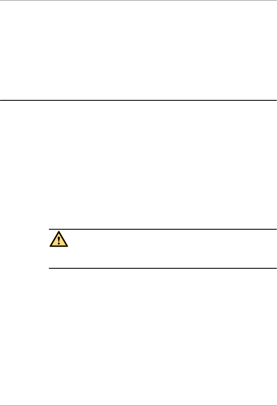
Step 6 Loosen the captive screws on the two contact pieces of the main bracket by using the M4
screwdriver, as shown in Figure 4-1.
RRU3908 V2
Hardware Maintenance Guide 4 Replacing the RRU
Issue 01 (2010-04-10) Huawei Proprietary and Confidential
Copyright © Huawei Technologies Co., Ltd.
4-1
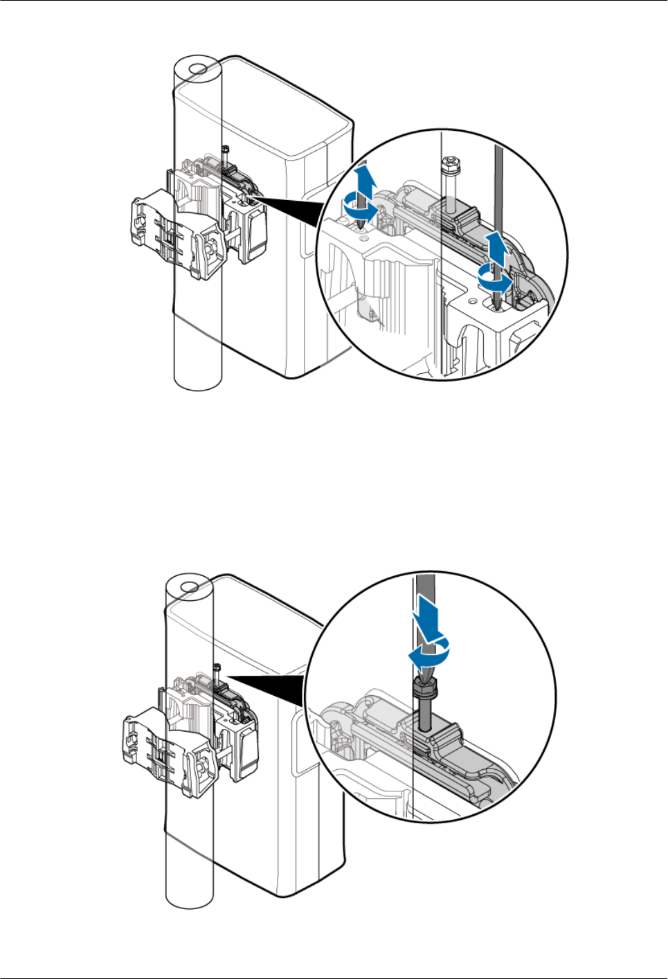
Figure 4-1 Loosening the captive screws on the main bracket
Step 7 Use an M6 screwdriver to tighten the screw on the adapting piece of the RRU, as shown in
Figure 4-2. Using the screw only for removing the RRU, loosen the connection between the
adapting piece and the main bracket, and then lift the bottom of the RRU to remove the RRU,
as shown in Figure 4-3.
Figure 4-2 Tightening the screws on the adapting piece
4 Replacing the RRU
RRU3908 V2
Hardware Maintenance Guide
4-2 Huawei Proprietary and Confidential
Copyright © Huawei Technologies Co., Ltd.
Issue 01 (2010-04-10)
Figure 4-3 Lifting the bottom of the RRU
Step 8 Tighten the captive screws on the two contact pieces of the main bracket until the tightening
torque reaches 1.4 N·m.
Step 9 Install a new RRU, and then waterproof the RRU.
Step 10 Insert all the cables to be connected to the RRU, and then check that the idle cables trough in
the cabling cavity are fitted with waterproof fillers.
Step 11 Close the cover plate of the cabling cavity of the RRU, and then tighten the screw for protecting
the cabling cavity on the cover plate until the tightening torque reaches 1.4 N·m.
Step 12 Power on the RRU. For details, see 3.1 Powering On the RRU.
Step 13 Check whether the new RRU is functional according to the status of the LEDs on the RRU. For
details about the LEDs, see RRU Indicators.
Step 14 Take off the ESD wrist strap or gloves, and then pack up all the tools.
----End
Postrequisite
lPlace the replaced RRU into the ESD box or bag. Then, place the ESD box or bag into a
carton padded with foam or into the packing box of the new RRU.
lFill in the fault form with the details of the replaced component.
lContact the local Huawei office to handle the faulty component.
RRU3908 V2
Hardware Maintenance Guide 4 Replacing the RRU
Issue 01 (2010-04-10) Huawei Proprietary and Confidential
Copyright © Huawei Technologies Co., Ltd.
4-3

5 Replacing the Optical Module
The optical module implements optical-electrical conversion, thus enabling optical transmission
between the RRU and other devices. You need to remove the optical cable before replacing the
optical module. Replacing the optical cable disrupts the transmission of CPRI signals.
Prerequisite
lThe types and quantity of faulty optical modules are confirmed, and new optical modules
are ready.
lThe tools and materials, such as an ESD wrist strap or ESD gloves, ESD box or bag, M4
screwdriver, and wrench are ready.
Context
lThe optical modules are installed on the CPRI0 and CPRI1 ports of the RRU.
lThe optical module is hot-swappable.
lIt takes about five minutes to replace the optical module of the RRU, which involves
disconnecting the optical cables, removing the faulty optical module, inserting a new optical
module, reconnecting the optical cables, and waiting for the CPRI links to resume.
Procedure
Step 1 Wear an ESD wrist strap or a pair of ESD gloves.
WARNING
Take proper ESD protection measures, for example, wear an ESD wrist strap or a pair of ESD
gloves, to prevent electrostatic damage to the boards, modules, or electronic components.
Step 2 Loosen the screw for protecting the cabling cavity on the cover plate by using the M4
screwdriver, and then open the cabling cavity of the RRU by lifting the handle on the cover plate.
Step 3 Record the connections of the optical modules and optical cables.
Step 4 Remove the DB15 connector from the alarm cable, press down the latch on the optical connector,
and then remove the connector from the faulty optical module.
RRU3908 V2
Hardware Maintenance Guide 5 Replacing the Optical Module
Issue 01 (2010-04-10) Huawei Proprietary and Confidential
Copyright © Huawei Technologies Co., Ltd.
5-1

WARNING
Do not look into the optical fiber with unprotected eyes after the optical cable is removed from
the optical fiber.
Step 5 Turn the puller of the optical module outwards, and then pull the puller until the optical module
is removed from the RRU.
Step 6 Install the new optical module onto the RRU.
Step 7 Insert the optical connector into the new optical module.
Step 8 According to the status of the LEDs on the CPRI0 and CPRI1 ports, determine whether the CPRI
links resume. For details about the LEDs, see RRU Indicators.
Step 9 Reinstall the DB15 connector on the alarm cable, close the cover plate for the cabling cavity of
the RRU, and then tighten the protection screw on the cover plate for the cabling cavity of the
RRU until the tightening torque reaches 1.4 N·m.
Step 10 Take off the ESD wrist strap or gloves, and then pack up all the tools.
----End
Postrequisite
lPlace the replaced optical module into the ESD box or bag. Then, place the ESD box or
bag into a carton padded with foam or into the packing box of the new module.
lFill in the fault form with the details of the replaced component.
lContact the local Huawei office to handle the faulty optical module.
5 Replacing the Optical Module
RRU3908 V2
Hardware Maintenance Guide
5-2 Huawei Proprietary and Confidential
Copyright © Huawei Technologies Co., Ltd.
Issue 01 (2010-04-10)