Huawei Technologies RRU3942 Multi-mode Multi-carriers Remote Radio Unit User Manual Installation Guide
Huawei Technologies Co.,Ltd Multi-mode Multi-carriers Remote Radio Unit Installation Guide
UserManual.wiki
>
Huawei Technologies
>
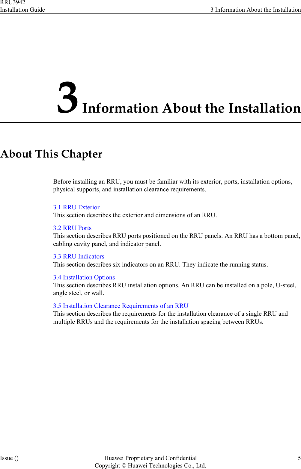
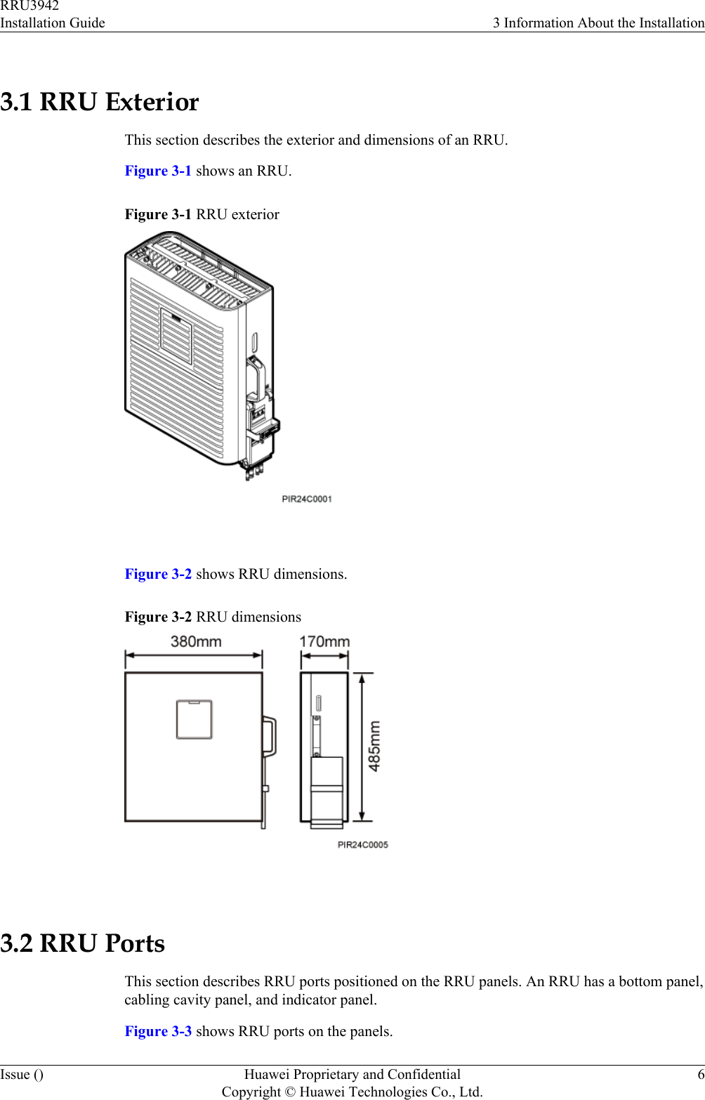
RRU3942 User Manual
Installation Guide
Navigation menu
Upload a User Manual
Namespaces
Wiki Guide
HTML
PDF
Info
Views
User Manual
Discussion / Help
Navigation
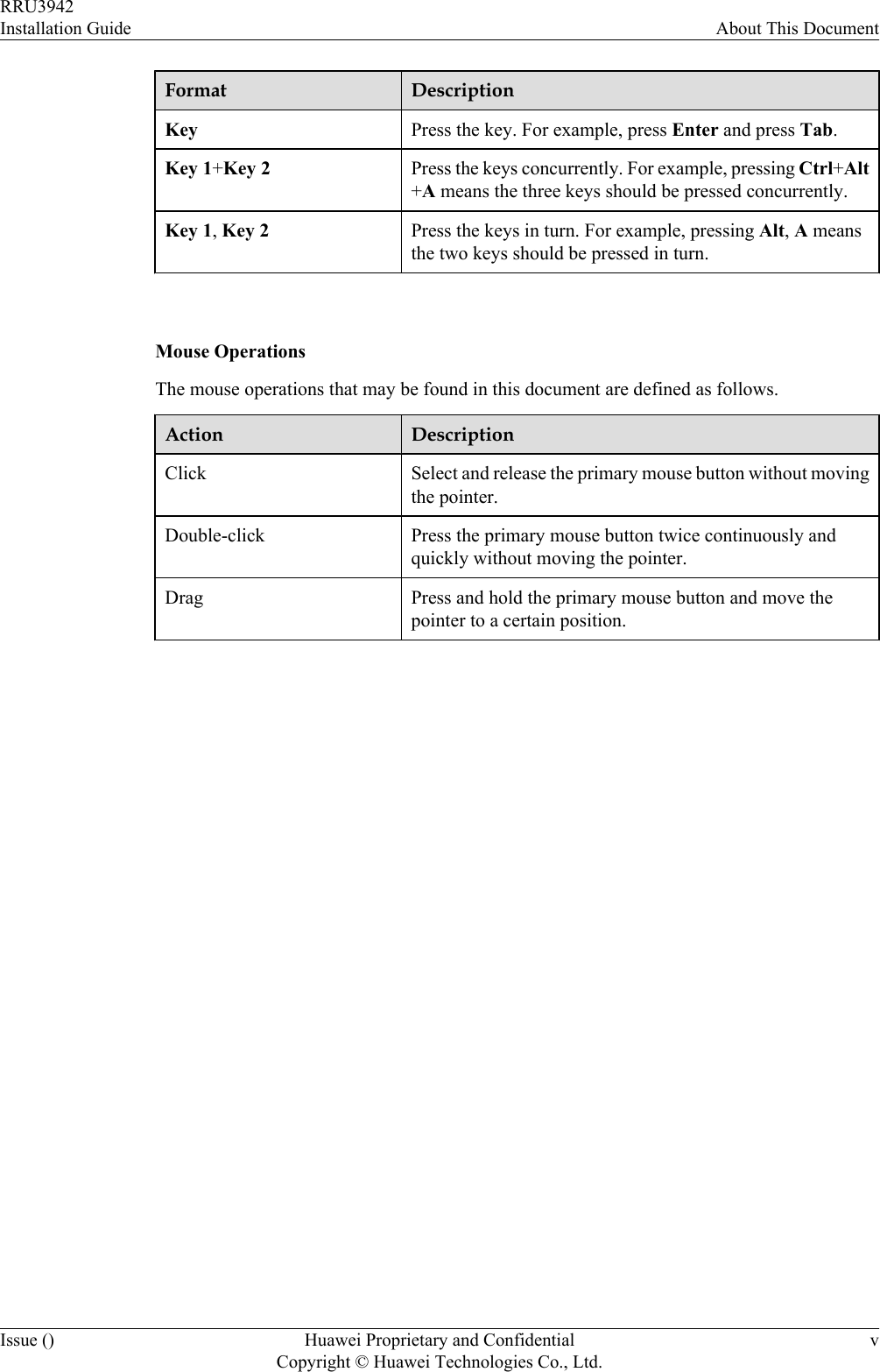
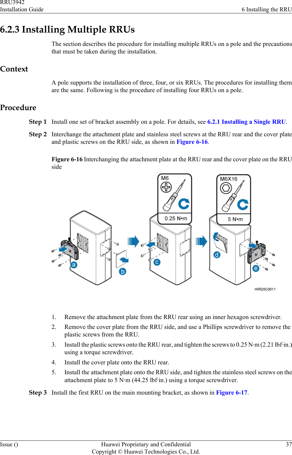
![Convention DescriptionTimes New Roman Normal paragraphs are in Times New Roman.Boldface Names of files, directories, folders, and users are inboldface. For example, log in as user root.Italic Book titles are in italics.Courier New Examples of information displayed on the screen are inCourier New. Command ConventionsThe command conventions that may be found in this document are defined as follows.Convention DescriptionBoldface The keywords of a command line are in boldface.Italic Command arguments are in italics.[ ] Items (keywords or arguments) in brackets [ ] are optional.{ x | y | ... } Optional items are grouped in braces and separated byvertical bars. One item is selected.[ x | y | ... ] Optional items are grouped in brackets and separated byvertical bars. One item is selected or no item is selected.{ x | y | ... }*Optional items are grouped in braces and separated byvertical bars. A minimum of one item or a maximum of allitems can be selected.[ x | y | ... ]*Optional items are grouped in brackets and separated byvertical bars. Several items or no item can be selected. GUI ConventionsThe GUI conventions that may be found in this document are defined as follows.Convention DescriptionBoldface Buttons, menus, parameters, tabs, window, and dialog titlesare in boldface. For example, click OK.>Multi-level menus are in boldface and separated by the ">"signs. For example, choose File > Create > Folder. Keyboard OperationsThe keyboard operations that may be found in this document are defined as follows.RRU3942Installation Guide About This DocumentIssue () Huawei Proprietary and ConfidentialCopyright © Huawei Technologies Co., Ltd.iv](https://usermanual.wiki/Huawei-Technologies/RRU3942/User-Guide-1617445-Page-5.png)
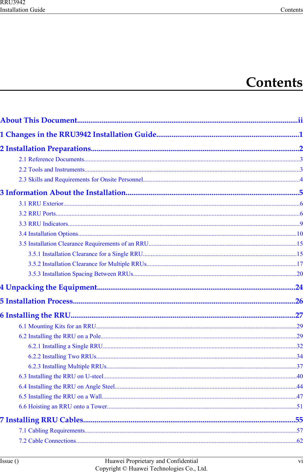
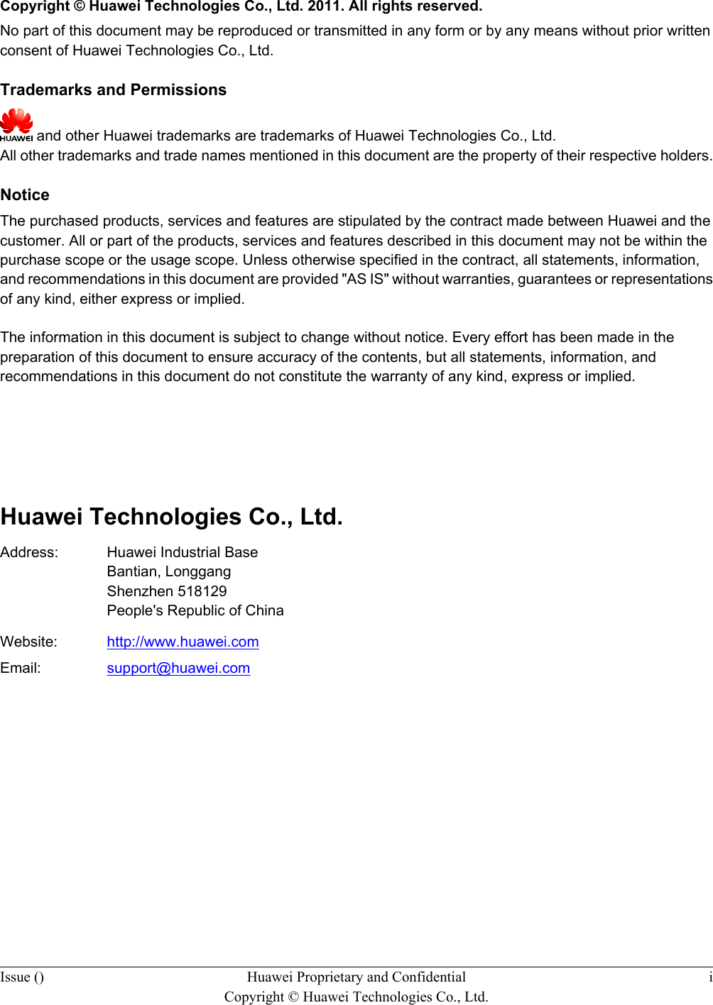
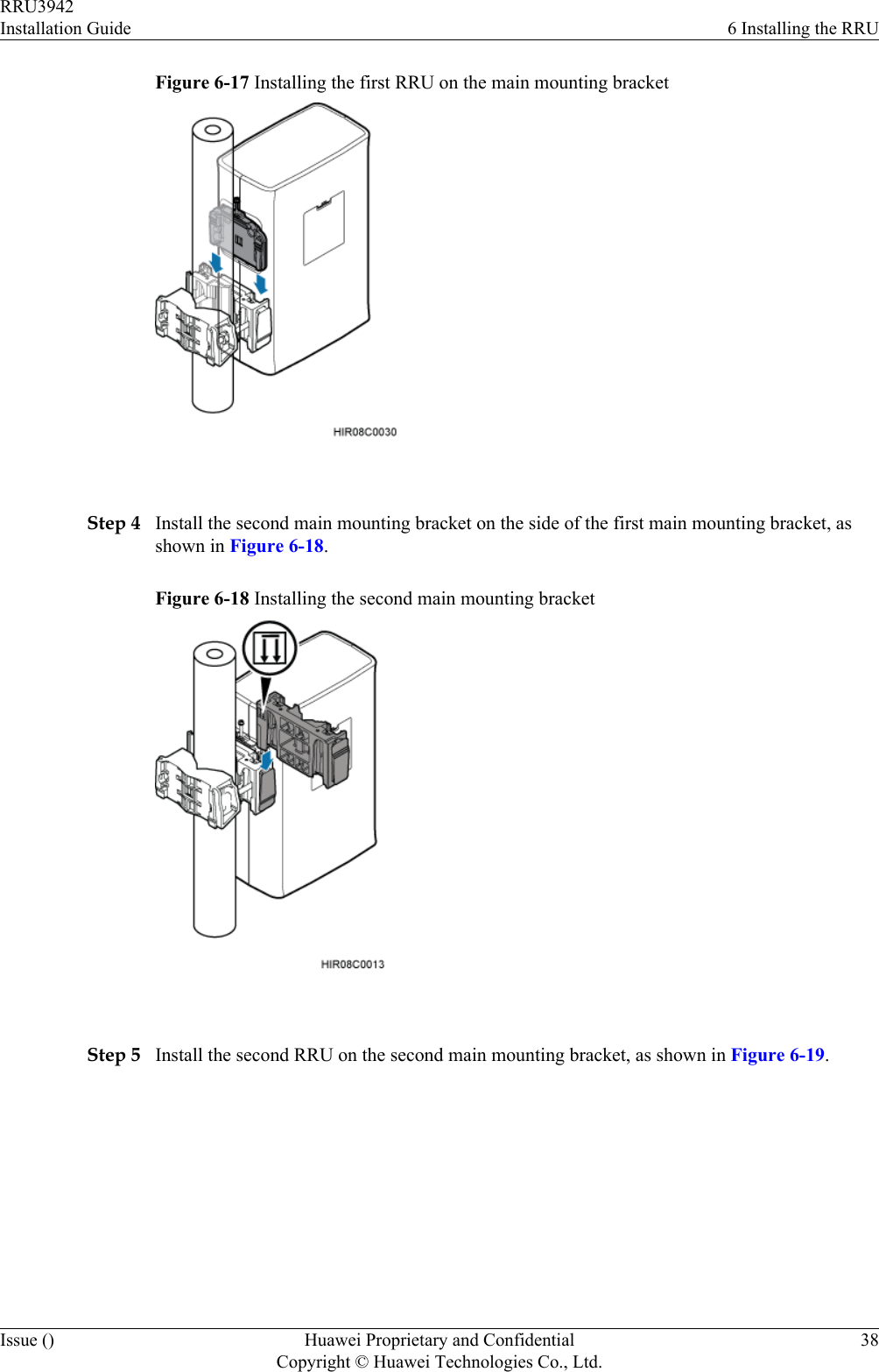
![2.1 Reference DocumentsBefore the installation, you must be familiar with reference documents.The following reference documents are required during RRU installation:lRRU3942 Hardware DescriptionlRRU3942 Hardware Maintenance GuidelDBS3900 Installation GuidelOCB User Guide2.2 Tools and InstrumentsAll tools and instruments required for RRU installation must be ready before the installation.Hammer drill (a φ 14 bit) ESD gloves Vacuum cleanerHeat gun Phillips screwdriver (M3 toM6)Flat-head screwdriver (M3 toM6)Rubber mallet COAX crimping tool Wire stripperUtility knife Cable cutter Adjustable wrench (capacity≥ 32 mm [1.26 in.])RRU3942Installation Guide 2 Installation PreparationsIssue () Huawei Proprietary and ConfidentialCopyright © Huawei Technologies Co., Ltd.3](https://usermanual.wiki/Huawei-Technologies/RRU3942/User-Guide-1617445-Page-11.png)
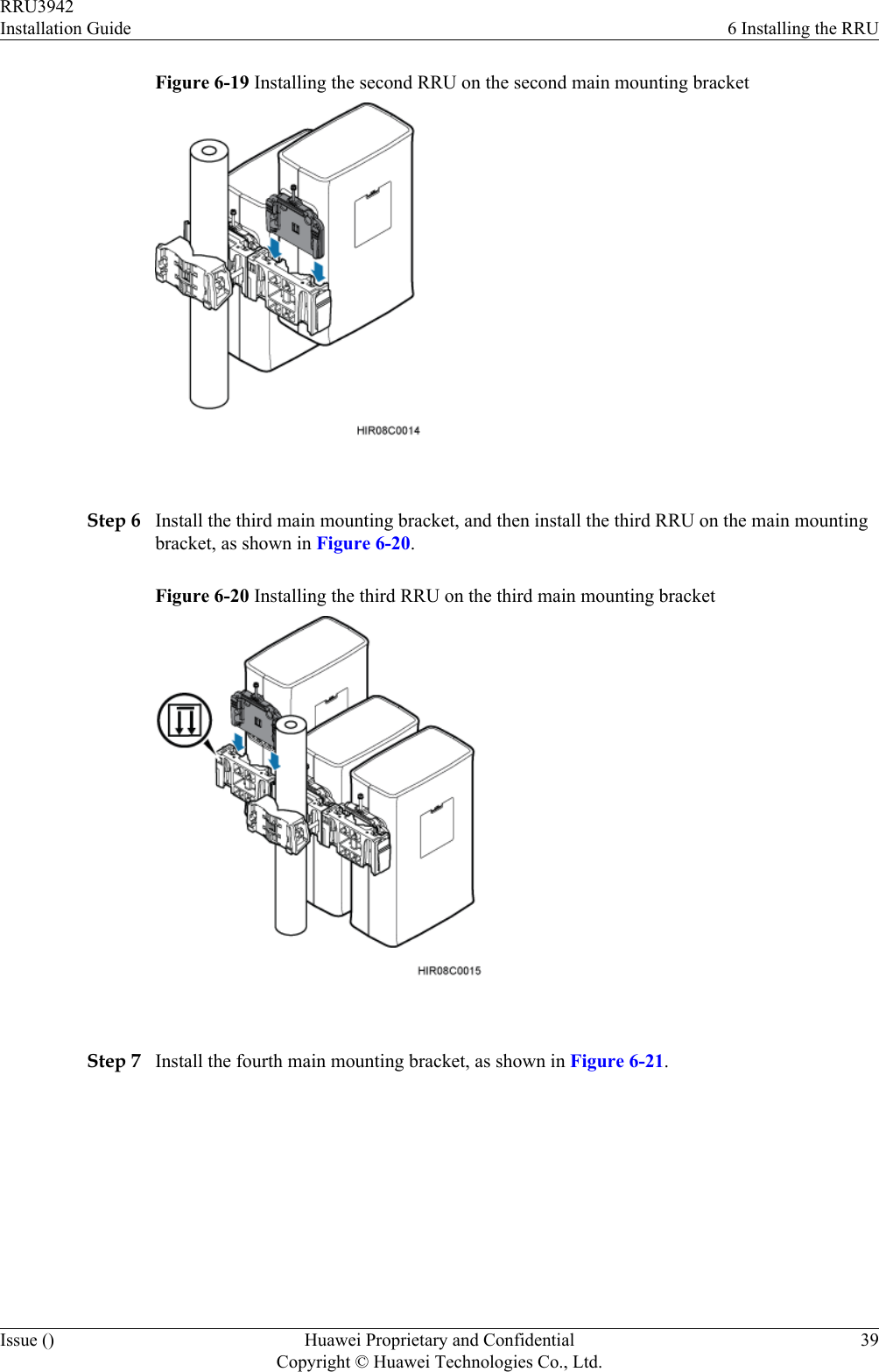
![Level Torque screwdriver5 mm(M3 to M6)(M3 to M6)Torque wrenchCapacity: 17 mm [0.67 in.], 21mm [0.82 in.], and 32 mm[1.26 in.]Combination wrenchCapacity: 17 mm [0.67 in.], 21mm [0.82 in.], and 32 mm[1.26 in.]Multimeter Marker (diameter ≤ 10 mm[0.39 in.])Measuring tape 2.3 Skills and Requirements for Onsite PersonnelOnsite personnel must be qualified and trained. Before performing any operation, onsitepersonnel must be familiar with correct operation methods and safety precautions.Before the installation, pay attention to the following items:lThe customer's technical engineers must be trained by Huawei and be familiar with theproper installation and operation methods.lThe number of onsite personnel depends on the engineering schedule and installationenvironment. Generally, only three to five onsite personnel are necessary.RRU3942Installation Guide 2 Installation PreparationsIssue () Huawei Proprietary and ConfidentialCopyright © Huawei Technologies Co., Ltd.4](https://usermanual.wiki/Huawei-Technologies/RRU3942/User-Guide-1617445-Page-12.png)

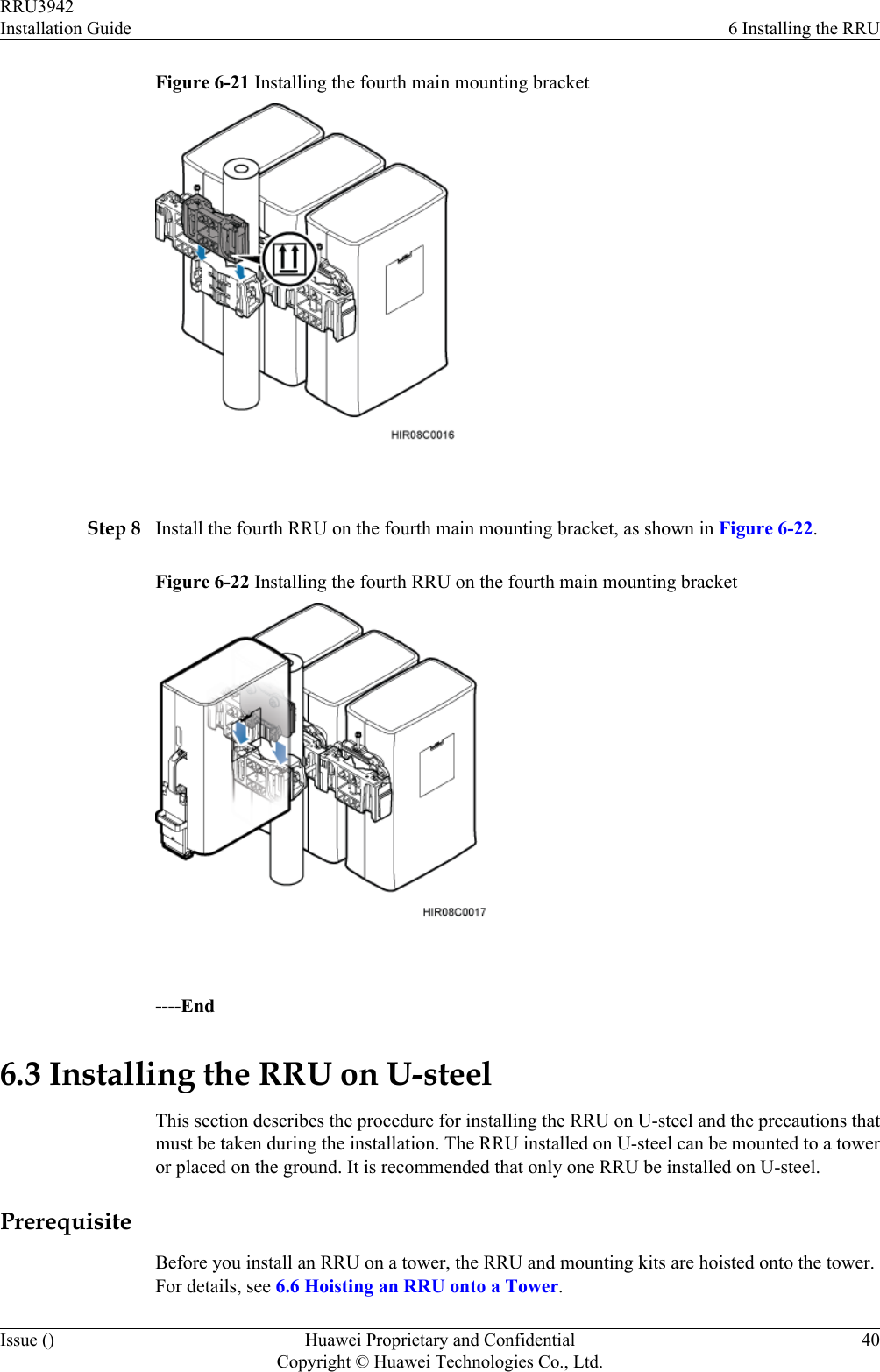
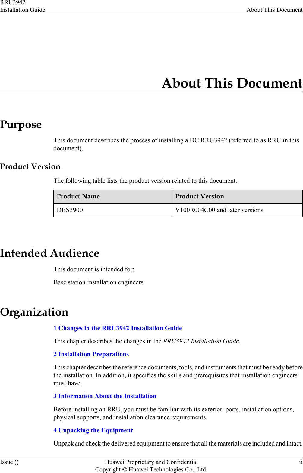
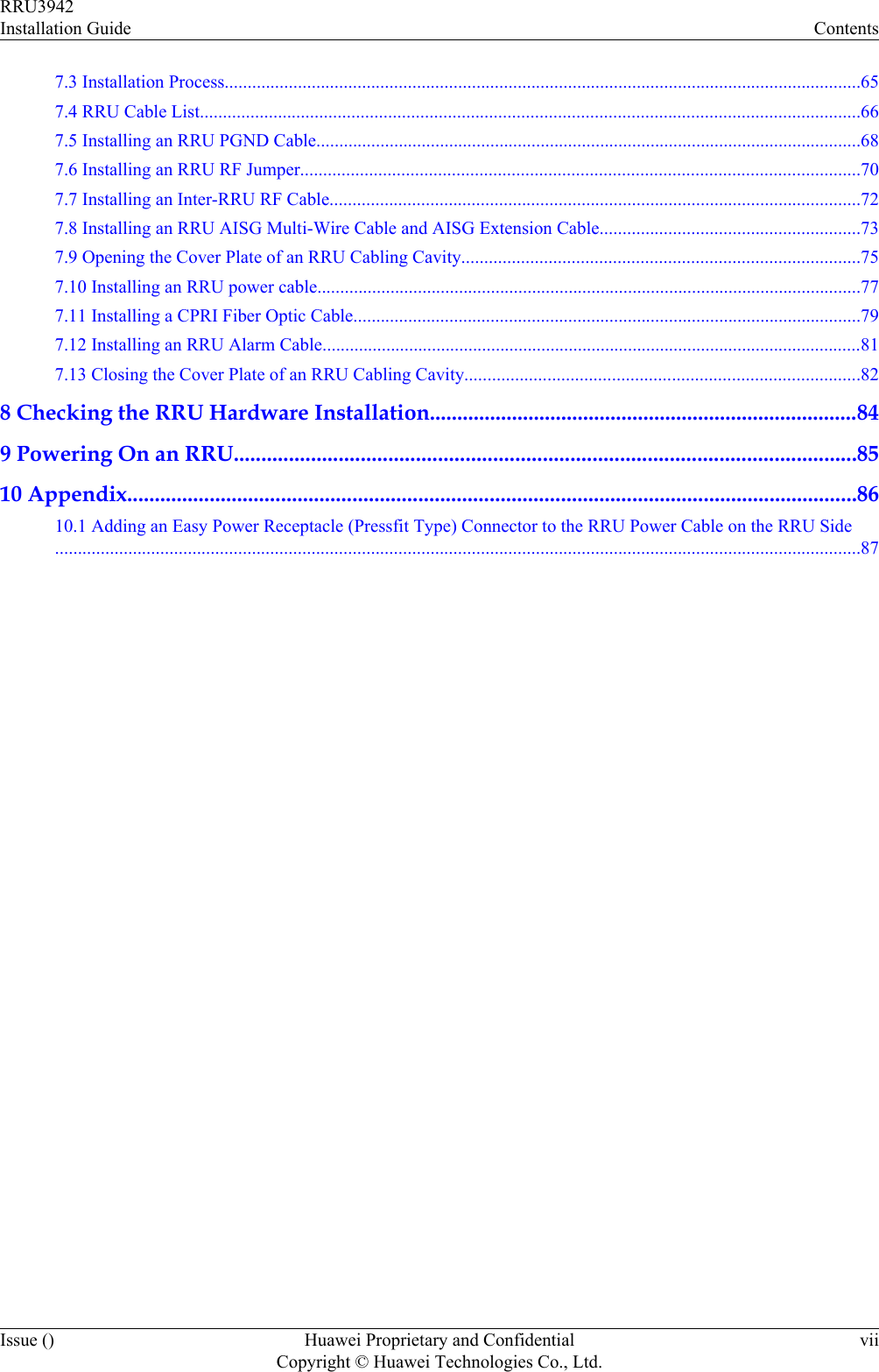
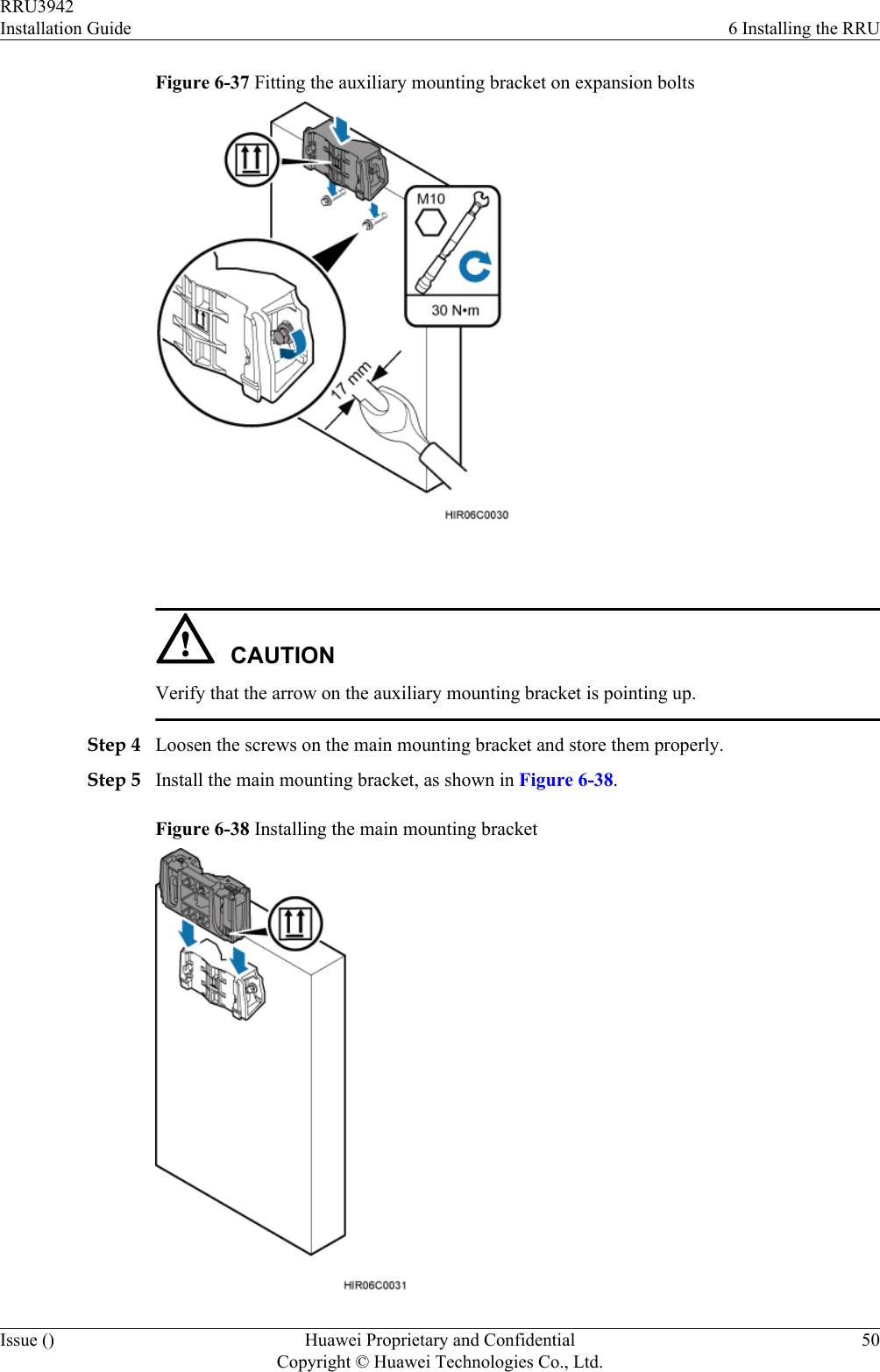
![Figure 6-36 Drilling a hole and inserting an expansion bolt assembly 1. Use a hammer drill with a φ14 bit to drill holes vertically at the marked anchor points.Ensure that the depth of each hole ranges from 55 mm (2.17 in.) to 60 mm (2.36 in.).WARNINGTake proper safety measures to protect your eyes and respiratory tract against the dustbefore drilling holes.2. Hit the expansion bolt with a rubber mallet until the expansion tube completely enters thehole.3. Tighten an expansion bolt slightly and place it vertically into each hole.4. Remove the M10x65 bolt, spring washer, plastic tube, and flat washer from each expansionbolt assembly in sequence.NOTEAfter completely removing an expansion bolt, store the plastic tube properly.5. Hammer the bolt into the wall.CAUTIONDo not hammer the expansion bolt entirely into the wall. Instead, leave 20 mm (0.79 in.)to 30 mm (1.18 in.) of the expansion bolt outside the wall.Step 3 Fit the auxiliary mounting bracket on the expansion bolt, and then use a torque wrench (17 mm[0.67 in.]) to tighten the expansion bolt to 30 N·m (265.52 lbf·in.), as shown in Figure 6-37.RRU3942Installation Guide 6 Installing the RRUIssue () Huawei Proprietary and ConfidentialCopyright © Huawei Technologies Co., Ltd.49](https://usermanual.wiki/Huawei-Technologies/RRU3942/User-Guide-1617445-Page-57.png)
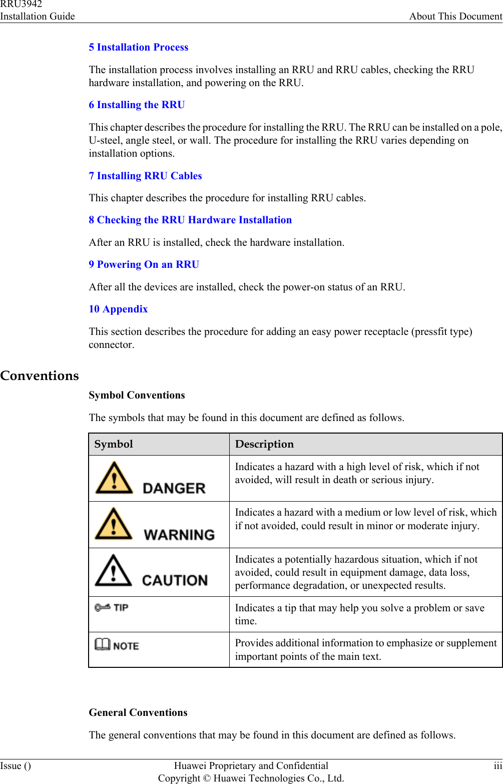
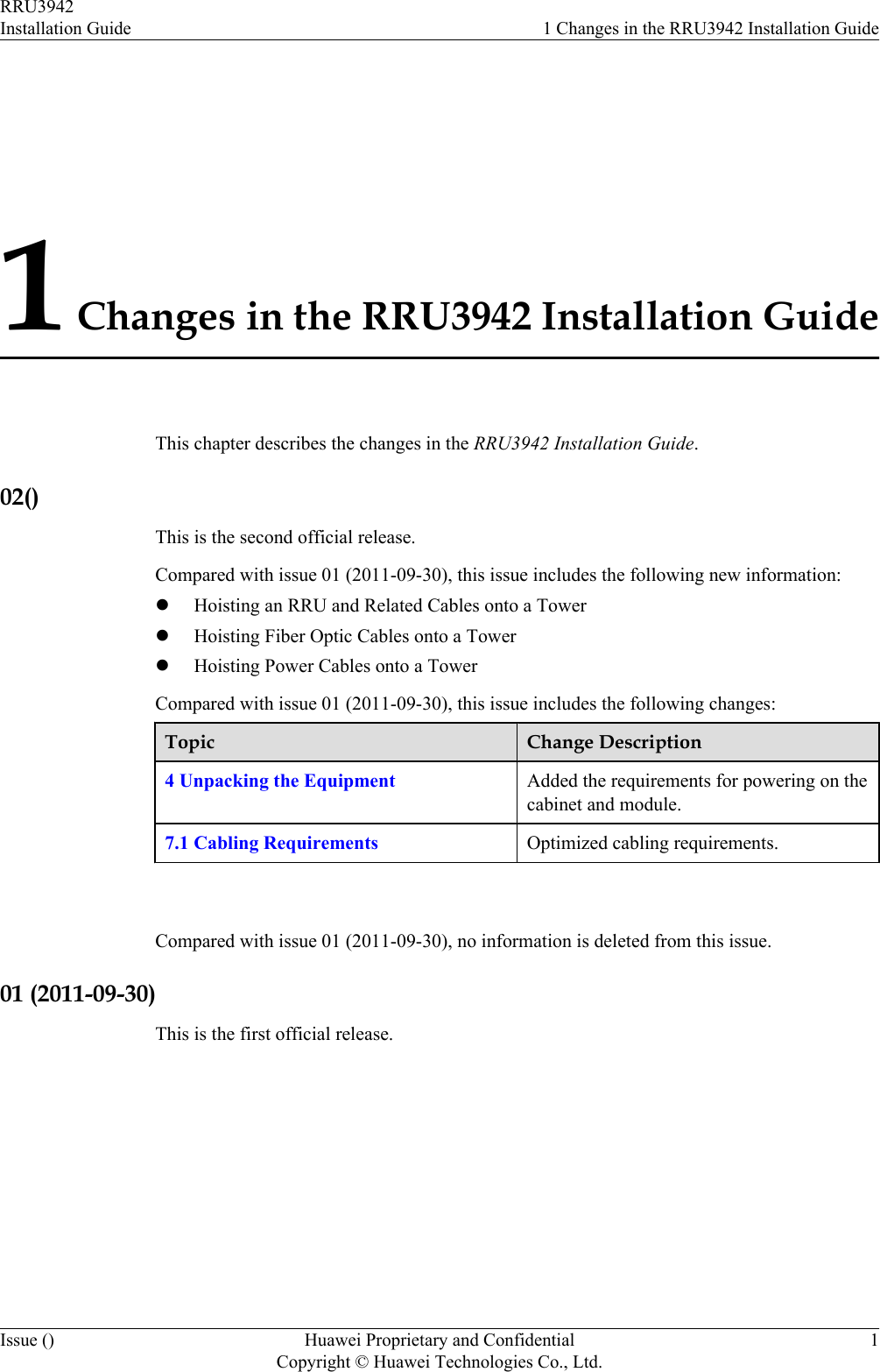
![CAUTIONlEach sling has a maximum load-bearing capacity of 200 kg (441 lb), the diameter of the slingmust be less than 25 mm (0.98 in.), and the angle at the top of the traction sling [by the knot]must not be greater than 60 degrees.lWhen hoisting the RRU and mounting kits onto the tower, protect them from colliding withthe ground and tower.lHoist the RRU onto the tower before it is installed on a pole, angle steel, or U-steel.lDo not hoist the RRU by the handle or lifting eye only, as shown in Figure 6-42 and Figure6-43.Figure 6-42 Incorrect binding method Figure 6-43 Incorrect binding methodRRU3942Installation Guide 6 Installing the RRUIssue () Huawei Proprietary and ConfidentialCopyright © Huawei Technologies Co., Ltd.53](https://usermanual.wiki/Huawei-Technologies/RRU3942/User-Guide-1617445-Page-61.png)

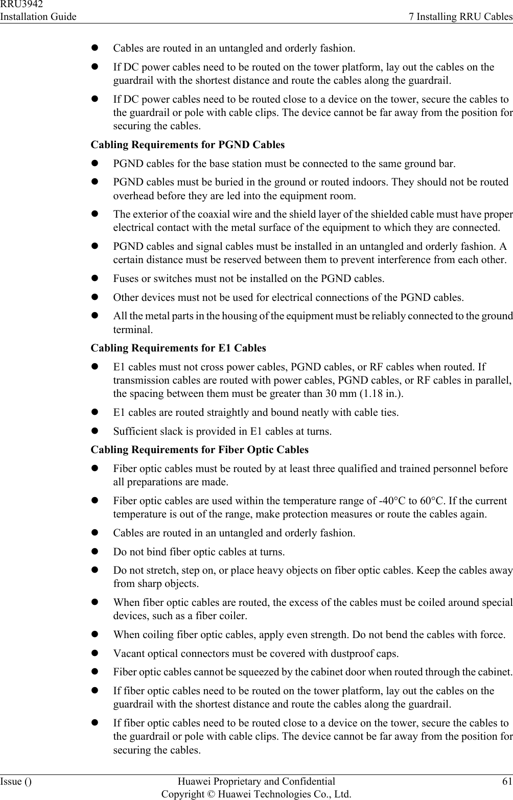
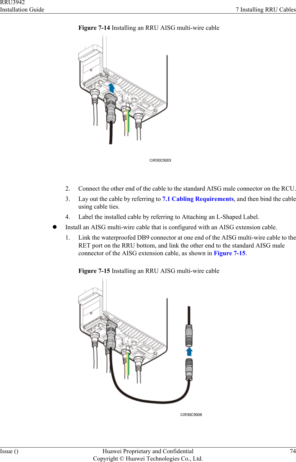
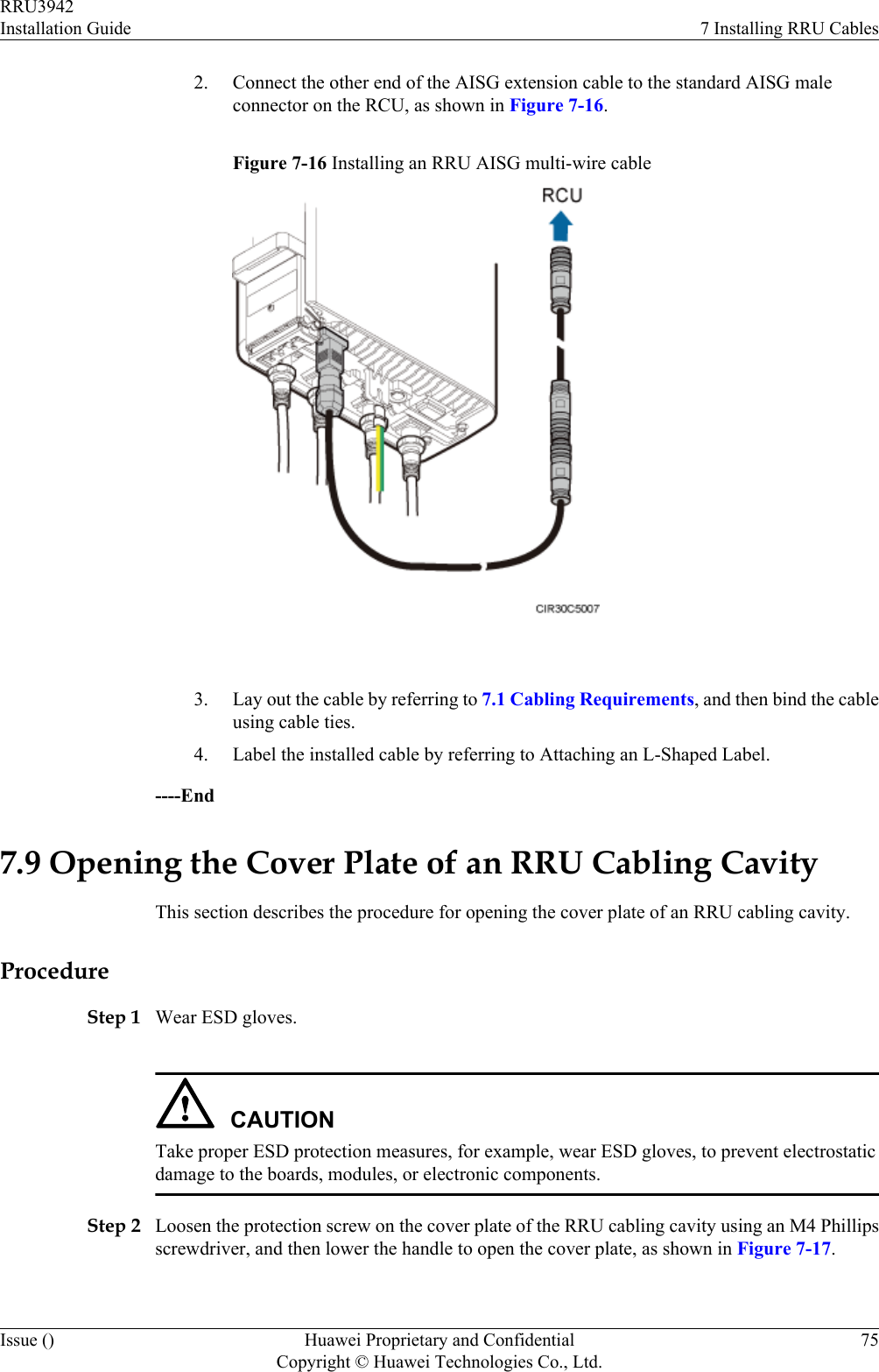
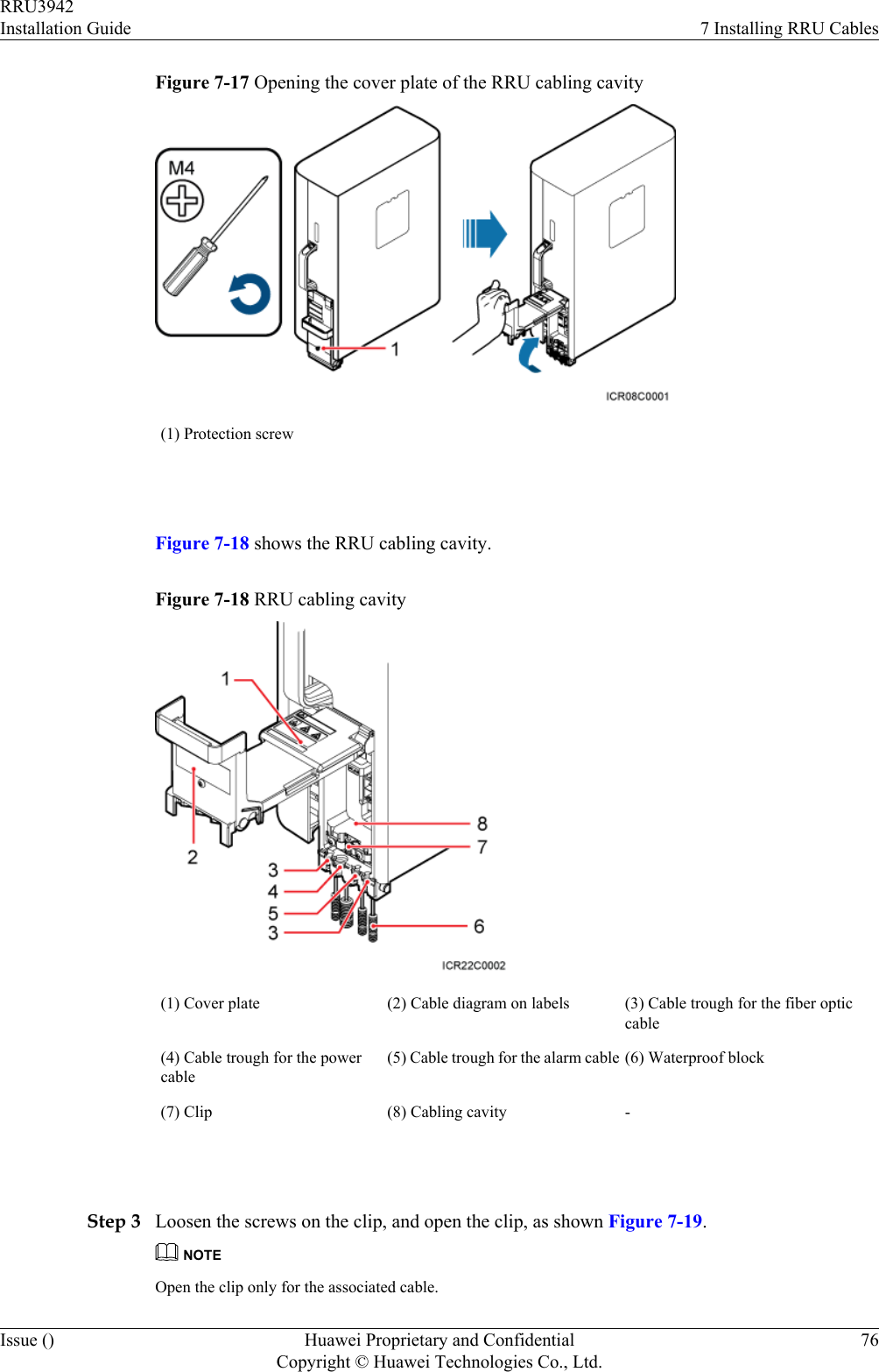
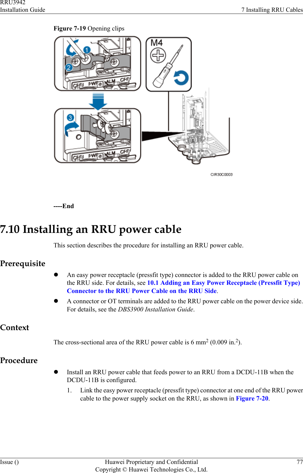
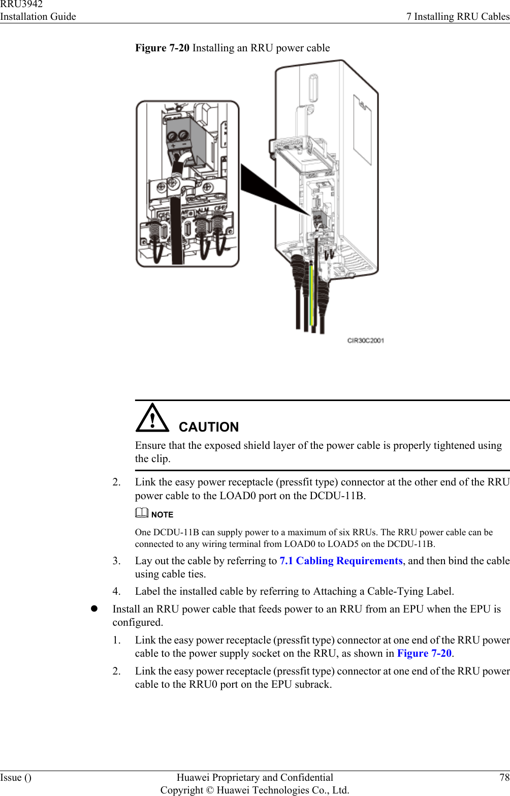
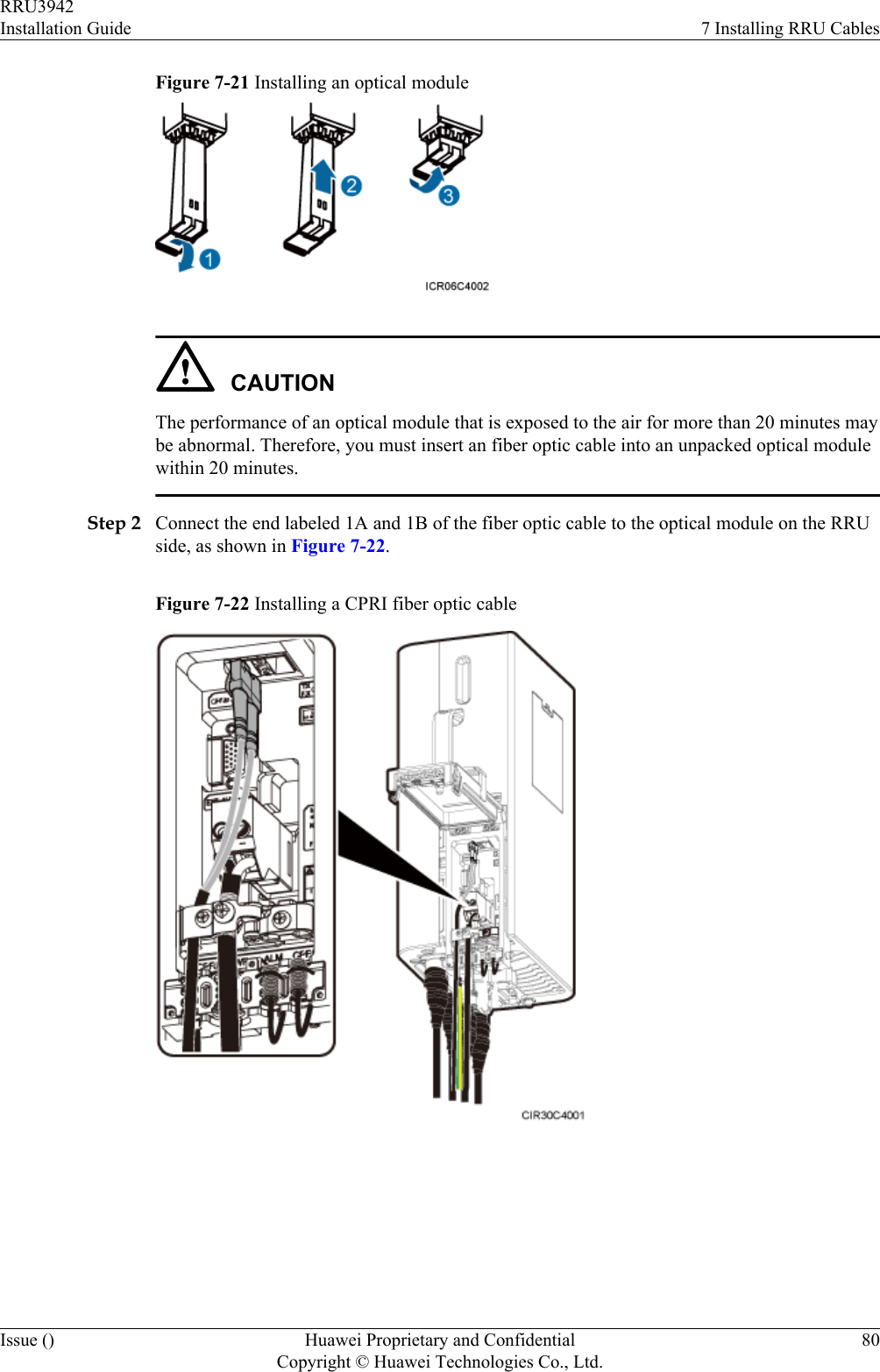
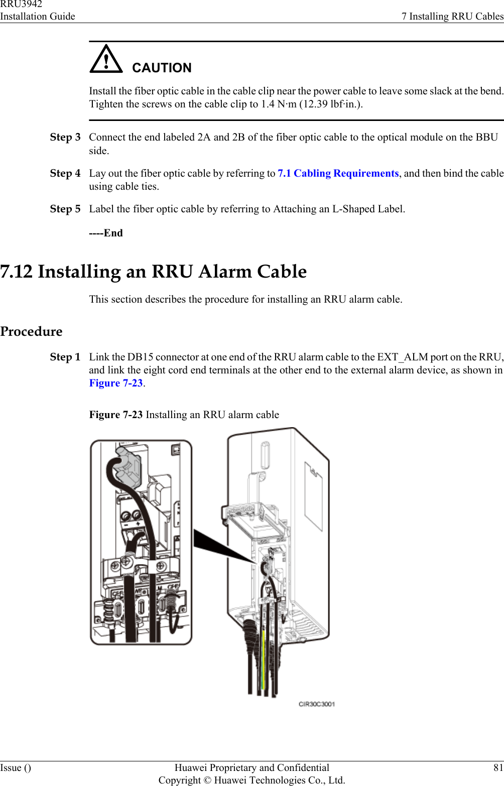
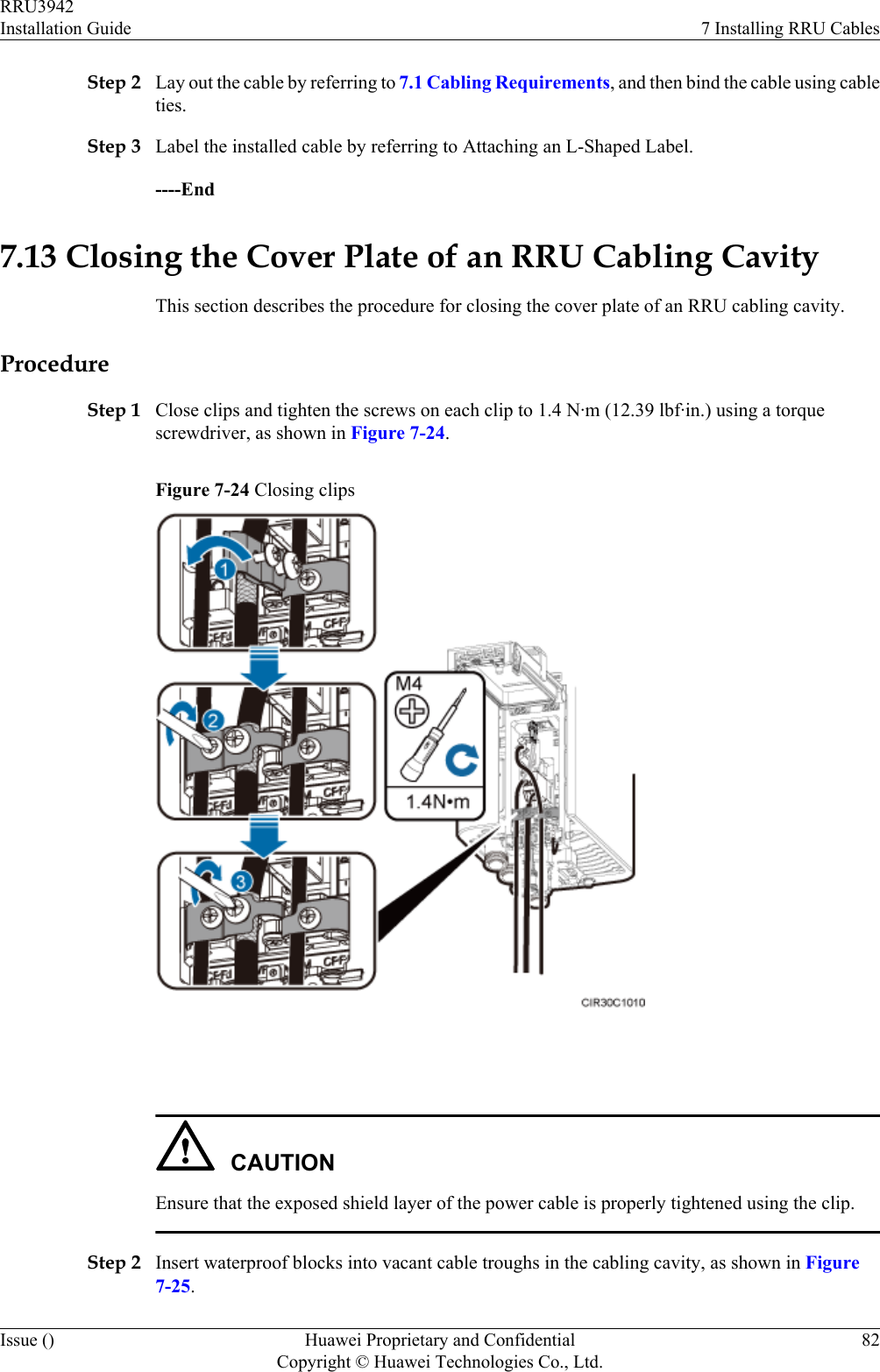
![7.1 Cabling RequirementsCables must be routed according to the specified cabling requirements to prevent signalinterference.NOTEIf a cable listed below is not required, skip the routing requirements of the cable.General Cabling RequirementsRequirements for Bending RadiuslThe bending radius of the 7/8'' feeder must be more than 250 mm (9.84 in.), and the bendingradius of the 5/4'' feeder must be more than 380 mm (14.96 in.).lThe bending radius of the 1/4'' jumper must be more than 35 mm (1.38 in.). The bendingradius of the super-flexible 1/2'' jumper must be more than 50 mm (1.97 in.), and the bendingradius of the ordinary 1/2'' jumper must be more than 127 mm (5 in.).lThe bending radius of the power cable or PGND cable must be at least three times thediameter of the cable.lThe bending radius of a fiber optic cable is at least 20 times the diameter of the fiber opticcable, and the minimum bending radius of the breakout cable at each end of the fiber opticcable is 30 mm (1.18 in.).lThe bending radius of the E1/T1 cable must be at least three times the diameter of the cable.lThe bending radius of the signal cable must be at least five times the diameter of the cable.Requirements for Cable BindinglThe same types of cable must be bound together.lDifferent types of cable must be separately routed with the minimum spacing of 30 mm(1.18 in.) and cannot be entangled.lThe cables must be bound tightly and neatly. The sheaths of the cables must not be damaged.lCable ties are installed in the same direction, and those at the same horizontal line must bein a straight line.lThe excess of indoor cable ties is trimmed off, and the excess of outdoor cable ties allowsabout 5 mm (0.2 in.), without remaining rough edges.lLabels or nameplates must be attached to both ends, joints, or turns of cables after they areinstalled.Security RequirementslCables should be placed away from sharp objects or wall burrs. If these positions areinevitable, protect the cables with protection pipes.lCables must be routed away from heat sources, or heat-insulation materials are addedbetween cables and heat sources.lSufficient slack (recommended for about 0.1 m [0.33 ft.]) is provided in cables at turns orthe position close to a device, facilitating cable and device maintenance.Indoor Cabling RequirementslCables are routed indoors through the feeder window.lDrip loops must be made outside the feeder window, and the requirements for the minimumbending radius are met.RRU3942Installation Guide 7 Installing RRU CablesIssue () Huawei Proprietary and ConfidentialCopyright © Huawei Technologies Co., Ltd.57](https://usermanual.wiki/Huawei-Technologies/RRU3942/User-Guide-1617445-Page-65.png)
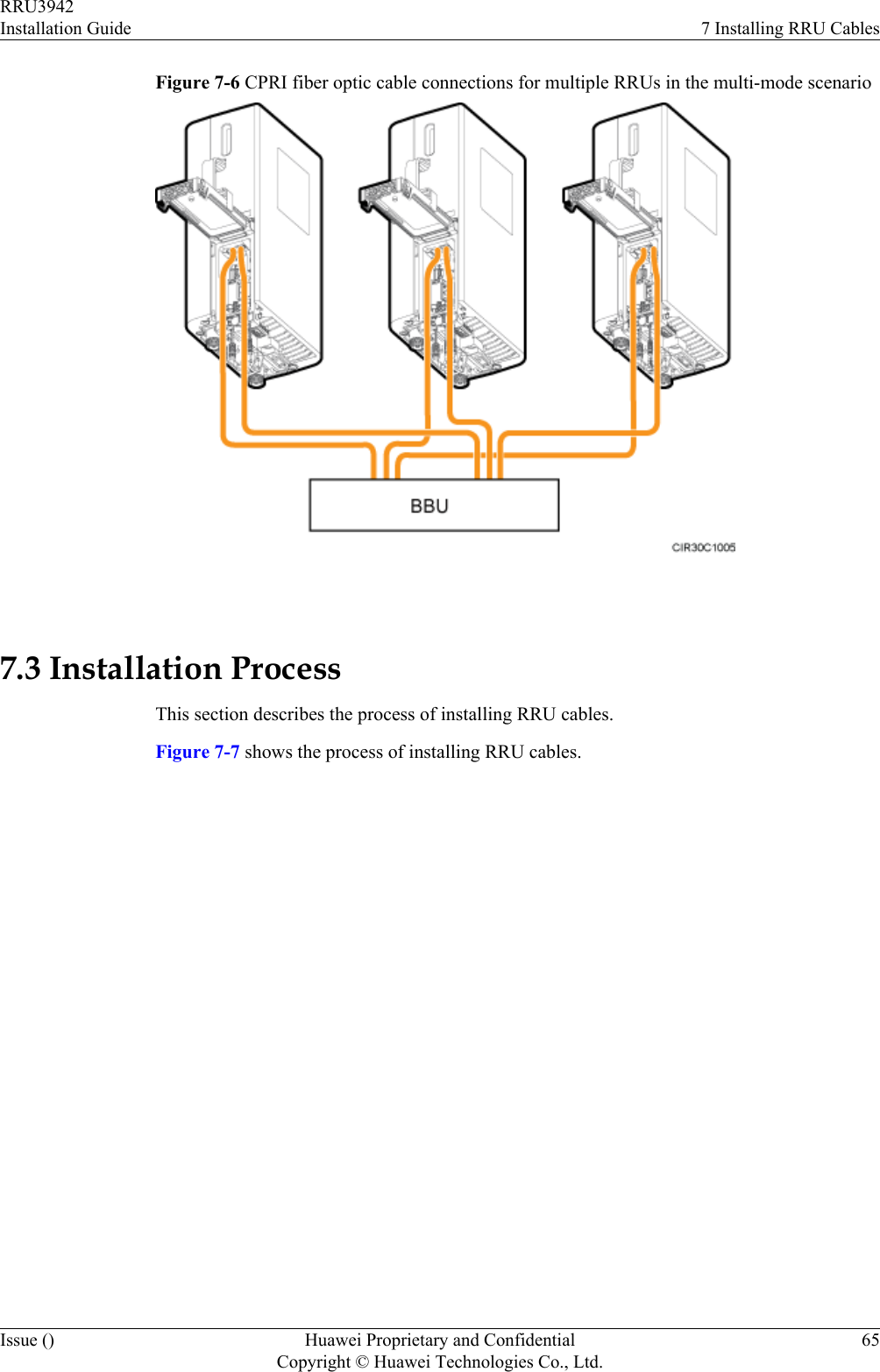
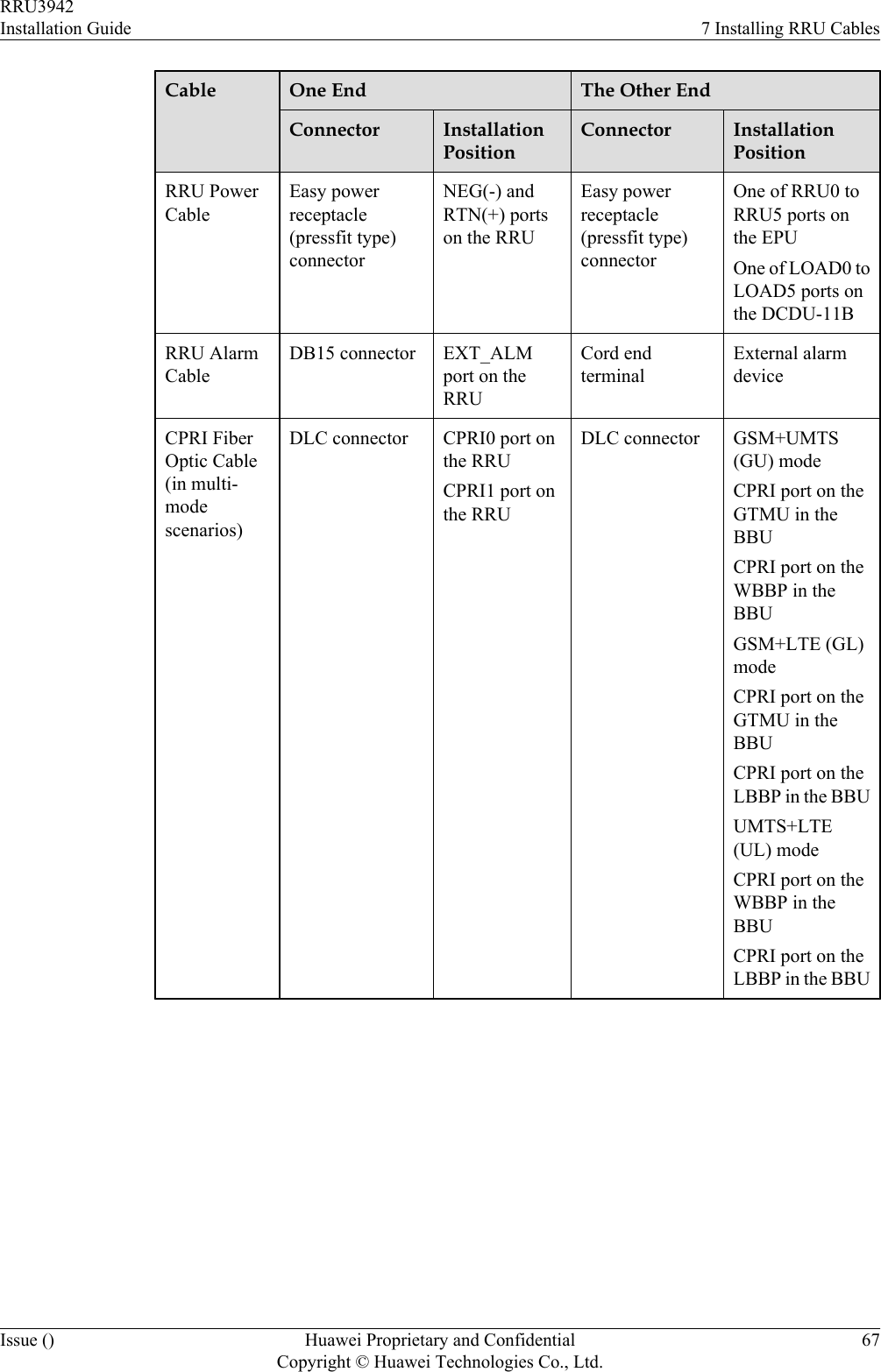
![Figure 7-7 Process of installing RRU cables 7.4 RRU Cable ListThis section describes RRU cable connections.Table 7-1 lists RRU cables.Table 7-1 RRU cablesCable One End The Other EndConnector InstallationPositionConnector InstallationPositionRRU PGNDCableOT terminal (M6,16 mm2 [0.025 in.2])Groundterminal on theRRUOT terminal(M8, 16 mm2[0.025 in.2])Ground terminalon the ground barRRU3942Installation Guide 7 Installing RRU CablesIssue () Huawei Proprietary and ConfidentialCopyright © Huawei Technologies Co., Ltd.66](https://usermanual.wiki/Huawei-Technologies/RRU3942/User-Guide-1617445-Page-74.png)

![CAUTIONEach core wire is exposed outside the easy power receptacle (pressfit type) connector for 1.5mm (0.059 [in.]), as shown in Figure 10-9.Figure 10-9 Inserting core wires into the easy power receptacle (pressfit type) connector ----EndRRU3942Installation Guide 10 AppendixIssue () Huawei Proprietary and ConfidentialCopyright © Huawei Technologies Co., Ltd.90](https://usermanual.wiki/Huawei-Technologies/RRU3942/User-Guide-1617445-Page-98.png)