Huawei Technologies UM01-HW Wireless Module supporting GSM/GPRS 850/1900 & WCDMA 850 User Manual
Huawei Technologies Co.,Ltd Wireless Module supporting GSM/GPRS 850/1900 & WCDMA 850
User Manual 1
HUAWEI UMTS M2M Module AT
Command Interface Specification
Prepared by Xu qifeng、Pei na、Ma zhaoyang Date 2009-02-03
Reviewed by Date
Approved by Date
Authorized by Date
Date Revisio
n
version
CR ID /
defect ID
Section
numbe
r Change description Author
2008-10-22 0.10 AT command interface draft
completed initially Yuan kangqiang
2009-02-03 0.20 Modify according to EM700
specification
Xu qifeng、Pei
na 、Ma
zhaoyang
Huawei Technologies Co., Ltd.
All rights reserved
(REP01T01 V2.31/ IPD-CMM V2.0 / for internal use only)
Product name Confidentiality level
HUAWEI UMTS M2M Module Confidential
Product version
V100R001
Total 95 pages
HUAWEI UMTS M2M Module AT Command Interface Specification Confidential
All rights reserved Page 2, Total 96
Notes:
Reinforced insulation or double insulation must be provided to isolate DC source from AC mains
supply.
Please observe the national local regulations in the location where product is to be used. This
product may be restricted for use in some or all countries of European Union.
The Radio Frequency (RF) exposure of the wireless module is determined by the final product
installation and the antenna selected by the module integrator.
Integrators of the wireless module device are responsible for ensuring that they meet the RF
exposure requirements or SAR requirements of the countries in which they intend to operate
the product. And relevant exposure information or SAR information shall be included in the
accompanying documents with the final products.
The antenna(s) used for this transmitter must be installed to provide a separation distance of at
least 20cm from all persons.
This device is intended for OEM integrators only.
Host system must be labeled with "Contains FCC ID: QISUM01-HW", FCC ID displayed on
label.
Notes:
z Disposal and Recycling Information
This symbol on the device (and any included batteries) indicates that they
should not be disposed of as normal household garbage. Do not dispose of
your device or batteries as unsorted municipal waste. The device (and any
batteries) should be handed over to a certified collection point for recycling
or proper disposal at the end of their life.
For more detailed information about the recycling of the device or batteries,
contact your local city office, the household waste disposal service, or the
retail store where you purchased this device.
The disposal of this device is subject to the Waste from Electrical and
Electronic Equipment (WEEE) directive of the European Union. The reason for
separating WEEE and batteries from other waste is to minimize the potential
environmental impacts on human health of any hazardous substances that may
be present.
z Reduction of Hazardous Substances
This device is compliant with the EU Registration, Evaluation, Authorisation and
Restriction of Chemicals (REACH) Regulation (Regulation No 1907/2006/EC of
the European Parliament and of the Council) and the EU Restriction of Hazardous
Substances (RoHS) Directive (Directive 2002/95/EC of the European Parliament
and of the Council). For more information about the REACH compliance of the
device, visit the Web site www.huaweidevice.com/certification. You are
recommended to visit the Web site regularly for up-to-date information.
z EU Regulatory Conformance
Hereby, Huawei Technologies Co., Ltd. declares that this device is in compliance
with the essential requirements and other relevant provisions of Directive
1999/5/EC.
For the declaration of conformity, visit the Web site
www.huaweidevice.com/certification.
z CE Marking

HUAWEI UMTS M2M Module AT Command Interface Specification Confidential
All rights reserved Page 3, Total 96
FCC Statement
15.19
NOTICE:
This device complies with Part 15 of the FCC Rules.Operation is subject to the following two
conditions:
(1) This device may not cause harmful interference, and 2) This device must accept any
interference received, including interference that may cause undesired operation.
15.21
NOTICE:
Changes or modifications made to this device not expressly approved by Huawei Technologies Co.,
Ltd. may void the FCC authorization to operate this device.
15.105
NOTE: This device has been tested and found to comply with the limits for a Class B digital device,
pursuant to Part 15 of the FCC Rules. These limits are designed to provide reasonable protection
against harmful interference in a residential installation. This device generates uses and can radiate
radio frequency energy and, if not installed and used in accordance with the instructions, may
cause harmful interference to radio communications. However, there is no guarantee that
interference will not occur in a particular installation. If this device does cause harmful interference
to radio or television reception, which can be determined by connecting or disconnecting the device
to a PC, the user is encouraged to try to correct the interference by adopting one or more of the
following measures:
Reorient or relocate the receiving antenna.
Increase the distance between the device and the receiver.
Connect the device to an outlet on a circuit different from that to which the receiver is connected.
Consult the dealer or an experienced radio or TV technician for help.
FCC Caution: Any changes or modifications not expressly approved by the party responsible for
compliance could void the user's authority to operate this device.

HUAWEI UMTS M2M Module AT Command Interface Specification Confidential
All rights reserved Page 4, Total 96
Table of Contents
HUAWEI UMTS M2M Module AT Command Interface Specification........................................... 1
Table of Contents ............................................................................................................................. 4
Table List......................................................................................................................................... 11
Figure List ....................................................................................................................................... 12
HUAWEI UMTS M2M Module AT Command Interface Specification ...................................... 13
1 Scope............................................................................................................................................ 14
1.1 Interface Overview.............................................................................................................. 14
1.2 Interface Design Principles .................................................................................................14
1.3 Interface Change Principles................................................................................................ 15
2 Interface Introduction ................................................................................................................. 15
3 Query of Basic Information and Description of Set Interface................................................. 16
3.1 Terminal error report command +CMEE ............................................................................ 16
3.1.1 Command Syntax..................................................................................................... 16
3.1.2 Description ...............................................................................................................16
3.1.3 Defined Values......................................................................................................... 16
3.2 Echo command E................................................................................................................ 16
3.2.1 Command Syntax..................................................................................................... 16
3.2.2 Description ...............................................................................................................17
3.2.3 Defined Values......................................................................................................... 17
3.3 Command line carriage return character S3....................................................................... 17
3.3.1 Command Syntax..................................................................................................... 17
3.3.2 Description ...............................................................................................................17
3.3.3 Defined Values......................................................................................................... 17
3.4 Response format character S4 ........................................................................................... 17
3.4.1 Command Syntax..................................................................................................... 17
3.4.2 Description ...............................................................................................................18
3.4.3 Defined Values......................................................................................................... 18
3.5 ME response format command V ....................................................................................... 18
3.5.1 Command Syntax..................................................................................................... 18
3.5.2 Description ...............................................................................................................18
3.5.3 Defined Values......................................................................................................... 18
3.6 Backspace character S5..................................................................................................... 19
3.6.1 Command Syntax..................................................................................................... 19
3.6.2 Description ...............................................................................................................19
3.6.3 Defined Values......................................................................................................... 19
3.7 RSSI query function command +CSQ ................................................................................ 19
3.7.1 Command Syntax..................................................................................................... 19
3.7.2 Description ...............................................................................................................19
3.7.3 Defined Values......................................................................................................... 19
3.8 RSSI level query function command + CSQLVL ................................................................ 19
3.8.1 Command Syntax..................................................................................................... 20
3.8.2 Interface Description ................................................................................................ 20
3.8.3 Defined Values......................................................................................................... 20
3.9 Operation mode setting command +CFUN ........................................................................ 20
3.9.1 Command Syntax..................................................................................................... 20
3.9.2 Description ...............................................................................................................20
3.9.3 Defined Values......................................................................................................... 21
3.10 Manufacturer information query command +CGMI .......................................................... 21

HUAWEI UMTS M2M Module AT Command Interface Specification Confidential
All rights reserved Page 5, Total 96
3.10.1 Command Syntax................................................................................................... 21
3.10.2 Description ............................................................................................................. 21
3.10.3 Defined Value......................................................................................................... 21
3.10.4 Informative Examples............................................................................................. 21
3.11 Software version number query command +CGMR......................................................... 21
3.11.1 Command Syntax................................................................................................... 21
3.11.2 Description ............................................................................................................. 21
3.11.3 Defined Value......................................................................................................... 22
3.12 IMSI query command +CIMI............................................................................................. 22
3.12.1 Command Syntax................................................................................................... 22
3.12.2 Interface Description .............................................................................................. 22
3.12.3 Defined Value......................................................................................................... 22
3.12.4 Informative Examples............................................................................................. 22
3.13 IMEI query command +CGSN .......................................................................................... 22
3.13.1 Command Syntax................................................................................................... 22
3.13.2 Interface Description .............................................................................................. 22
3.13.3 Defined Value......................................................................................................... 23
3.13.4 Informative Examples............................................................................................. 23
3.14 SPN read function command %SPN ................................................................................ 23
3.14.1 Command Syntax................................................................................................... 23
3.14.2 Description ............................................................................................................. 23
3.14.3 Defined Values....................................................................................................... 23
3.14.4 Informative Examples............................................................................................. 24
3.15 Hardware version number query function %HWVER....................................................... 24
3.15.1 Command Syntax................................................................................................... 24
3.15.2 Description ............................................................................................................. 24
3.15.3 Defined Value......................................................................................................... 24
3.16 Unsolicited report control command %CURC .................................................................. 24
3.16.1 Command Syntax................................................................................................... 24
3.16.2 Interface Description .............................................................................................. 25
3.16.3 Defined Values....................................................................................................... 25
3.17 Product model ID command +CGMM/+GMM................................................................... 25
3.17.1 Command Syntax................................................................................................... 25
3.17.2 Interface Description .............................................................................................. 25
3.17.3 Defined Value......................................................................................................... 25
3.18 Network information query %NWINFO............................................................................. 26
3.18.1 Command Syntax................................................................................................... 26
3.18.2 Interface Description .............................................................................................. 26
3.18.3 Defined Values....................................................................................................... 26
3.19 Temperature of PA and source voltage query %CONINFO............................................. 27
3.19.1 Command Syntax................................................................................................... 27
3.19.2 Interface Description .............................................................................................. 27
3.19.3 Defined Values....................................................................................................... 27
3.20 Voltage warning %WARNVOLT ....................................................................................... 27
3.20.1 Command Syntax................................................................................................... 27
3.20.2 Interface Description .............................................................................................. 27
3.20.3 Defined Values....................................................................................................... 27
3.21 Module delay resetting %RESET ..................................................................................... 28
3.21.1 Command Syntax................................................................................................... 28
3.21.2 Interface Description .............................................................................................. 28
3.21.3 Defined Values....................................................................................................... 28
3.22 Clock +CCLK .................................................................................................................... 28
3.22.1 Command Syntax................................................................................................... 28
3.22.2 Interface Description .............................................................................................. 28
3.22.3 Defined Values....................................................................................................... 28

HUAWEI UMTS M2M Module AT Command Interface Specification Confidential
All rights reserved Page 6, Total 96
4 SMS Interface Description.......................................................................................................... 29
4.1 Select the SMS type +CSMS.............................................................................................. 29
4.1.1 Command Syntax..................................................................................................... 29
4.1.2 Description ...............................................................................................................29
4.1.3 Defined Values......................................................................................................... 29
4.2 Set message format +CMGF.............................................................................................. 29
4.2.1 Command Syntax..................................................................................................... 29
4.2.2 Description ...............................................................................................................30
4.2.3 Defined Values......................................................................................................... 30
4.3 Message arrival indication +CMTI ...................................................................................... 30
4.3.1 Command Syntax..................................................................................................... 30
4.3.2 Description ...............................................................................................................30
4.3.3 Defined Values......................................................................................................... 30
4.4 Indication of new message reported directly +CMT ........................................................... 31
4.4.1 Command Syntax..................................................................................................... 31
4.4.2 Description ...............................................................................................................31
4.4.3 Defined Values......................................................................................................... 31
4.5 Newly received message state report +CDSI..................................................................... 31
4.5.1 Command Syntax..................................................................................................... 31
4.5.2 Description ...............................................................................................................31
4.5.3 Defined Values......................................................................................................... 31
4.6 Indication of new message state report reported directly +CDS ........................................ 31
4.6.1 Command Syntax..................................................................................................... 31
4.6.2 Description ...............................................................................................................32
4.6.3 Defined Values......................................................................................................... 32
4.7 New message notification setting +CNMI........................................................................... 32
4.7.1 Command Syntax..................................................................................................... 32
4.7.2 Description ...............................................................................................................33
4.7.3 Defined Values......................................................................................................... 33
4.7.4 Informative Examples............................................................................................... 35
4.8 Delete Message +CMGD.................................................................................................... 35
4.8.1 Command Syntax..................................................................................................... 35
4.8.2 Description ...............................................................................................................35
4.8.3 Defined Values......................................................................................................... 36
4.9 New Message Acknowledgement to +CNMA..................................................................... 36
4.9.1 Command Syntax..................................................................................................... 36
4.9.2 Description ...............................................................................................................36
4.9.3 Defined Values......................................................................................................... 37
4.10 Message storage selection +CPMS ................................................................................. 40
4.10.1 Command Syntax................................................................................................... 40
4.10.2 Description ............................................................................................................. 41
4.10.3 Defined Values....................................................................................................... 41
4.11 Reporting message storage media being full %SMMEMFULL ........................................ 42
4.11.1 Command Syntax................................................................................................... 42
4.11.2 Description ............................................................................................................. 42
4.11.3 Defined Values....................................................................................................... 42
4.12 SMSC number command +CSCA .................................................................................... 42
4.12.1 Command Syntax................................................................................................... 42
4.12.2 Description ............................................................................................................. 42
4.12.3 Defined Values....................................................................................................... 43
4.13 Message sending +CMGS................................................................................................ 43
4.13.1 Command Syntax................................................................................................... 43
4.13.2 Interface Description .............................................................................................. 43
4.13.3 Defined Values....................................................................................................... 43
4.13.4 Examples................................................................................................................ 48
4.14 Message storage command +CMGW .............................................................................. 49

HUAWEI UMTS M2M Module AT Command Interface Specification Confidential
All rights reserved Page 7, Total 96
4.14.1 Command Syntax................................................................................................... 49
4.14.2 Interface Description .............................................................................................. 49
4.14.3 Defined Values....................................................................................................... 49
4.15 Message list command +CMGL ....................................................................................... 50
4.15.1 Command Syntax................................................................................................... 50
4.15.2 Description ............................................................................................................. 50
4.15.3 Defined Values....................................................................................................... 50
4.16 Read a message +CMGR................................................................................................. 52
4.16.1 Command Syntax................................................................................................... 52
4.16.2 Description ............................................................................................................. 52
4.16.3 Defined Values....................................................................................................... 52
4.17 Message bearer domain command +CGSMS.................................................................. 52
4.17.1 Command Syntax................................................................................................... 52
4.17.2 Description ............................................................................................................. 53
4.17.3 Defined Values....................................................................................................... 53
4.18 More Messages to Send +CMMS..................................................................................... 53
4.18.1 Command Syntax................................................................................................... 53
4.18.2 Description ............................................................................................................. 53
4.18.3 Defined Values....................................................................................................... 53
5 Description of Security Setting Interface.................................................................................. 54
5.1 PIN password modifying +CPWD....................................................................................... 54
5.1.1 Command Syntax..................................................................................................... 54
5.1.2 Description ...............................................................................................................54
5.1.3 Defined Values......................................................................................................... 54
5.2 PIN enabling and query function +CLCK............................................................................ 54
5.2.1 Command Syntax..................................................................................................... 55
5.2.2 Description ...............................................................................................................55
5.2.3 Defined Values......................................................................................................... 55
5.3 PIN management command +CPIN ................................................................................... 55
5.3.1 Command Syntax..................................................................................................... 55
5.3.2 Description ...............................................................................................................56
5.3.3 Defined Values......................................................................................................... 56
5.4 SIMLOCK unlocking and query command %SIMLOCK .................................................. 56
5.4.1 Command Syntax..................................................................................................... 56
5.4.2 Interface Description ................................................................................................ 57
5.4.3 Defined Values......................................................................................................... 57
6 System Setting Interface Description........................................................................................ 57
6.1 System information query %SYSINFO............................................................................... 57
6.1.1 Command Syntax..................................................................................................... 57
6.1.2 Interface Description ................................................................................................ 57
6.1.3 Defined Values......................................................................................................... 57
6.2 Service state change indication %SRVST.......................................................................... 58
6.2.1 Command Syntax..................................................................................................... 58
6.2.2 Description ...............................................................................................................59
6.2.3 Defined Values......................................................................................................... 59
6.3 SIM state change indication %SIMST ................................................................................ 59
6.3.1 Command Syntax..................................................................................................... 59
6.3.2 Interface Description ................................................................................................ 59
6.3.3 Defined Values......................................................................................................... 59
6.4 System mode change event indication %MODE................................................................ 59
6.4.1 Command Syntax..................................................................................................... 59
6.4.2 Interface Description ................................................................................................ 60
6.4.3 Defined Values......................................................................................................... 60
6.5 RSSI change indication %RSSI.......................................................................................... 60
6.5.1 Command Syntax..................................................................................................... 60

HUAWEI UMTS M2M Module AT Command Interface Specification Confidential
All rights reserved Page 8, Total 96
6.5.2 Description ...............................................................................................................60
6.5.3 Defined Values......................................................................................................... 60
6.6 System configuration reference setting %SYSCFG ........................................................... 61
6.6.1 Command Syntax..................................................................................................... 61
6.6.2 Description ...............................................................................................................61
6.6.3 Defined Values......................................................................................................... 61
7 Phonebook Service Interface Description................................................................................ 62
7.1 Phonebook memory selection +CPBS ............................................................................... 62
7.1.1 Command Syntax..................................................................................................... 62
7.1.2 Description ...............................................................................................................62
7.1.3 Defined Values......................................................................................................... 63
7.2 8.13 Find phonebook entries +CPBF......................................................................... 63
7.2.1 command syntax ...................................................................................................... 63
7.2.2 Description ...............................................................................................................63
7.2.3 Defined values.......................................................................................................... 64
7.3 Read phonebook entries +CPBR ....................................................................................... 64
7.3.1 Command syntax ..................................................................................................... 64
7.3.2 Description ...............................................................................................................64
7.3.3 Defined values.......................................................................................................... 65
7.4 Write phonebook entry +CPBW.......................................................................................... 65
7.4.1 command syntax ...................................................................................................... 65
7.4.2 Description ...............................................................................................................65
7.4.3 Defined values.......................................................................................................... 65
7.5 Phonebook reading %CPBR .............................................................................................. 66
7.5.1 Command Syntax..................................................................................................... 66
7.5.2 Description ...............................................................................................................66
7.5.3 Defined Values......................................................................................................... 66
7.6 Phonebook writing %CPBW ............................................................................................... 67
7.6.1 Command Syntax..................................................................................................... 67
7.6.2 Description ...............................................................................................................67
7.6.3 Defined Values......................................................................................................... 68
7.6.4 Informative Examples............................................................................................... 68
8 Network Service Interface Description ..................................................................................... 68
8.1 Operator selection +COPS ................................................................................................. 68
8.1.1 Command Syntax..................................................................................................... 68
8.1.2 Interface Description ................................................................................................ 69
8.1.3 Defined Values......................................................................................................... 69
8.1.4 Examples of searching network ............................................................................... 70
8.2 Network registration +CREG .............................................................................................. 70
8.2.1 Command Syntax..................................................................................................... 70
8.2.2 Interface Description ................................................................................................ 71
8.2.3 Defined Values......................................................................................................... 71
8.3 Network registration +CGREG ........................................................................................... 71
8.3.1 Command Syntax..................................................................................................... 71
8.3.2 Interface Description ................................................................................................ 72
8.3.3 Defined Values......................................................................................................... 72
9 Data Service Interface Description............................................................................................72
9.1 3G Quality of Service Profile (Negotiated) +CGEQNEG .................................................... 72
9.1.1 Command Syntax..................................................................................................... 72
9.1.2 Description ...............................................................................................................73
9.1.3 Defined values.......................................................................................................... 73
9.2 Enter data state +CGDATA ................................................................................................ 74
9.2.1 Command Syntax..................................................................................................... 74
9.2.2 Description ...............................................................................................................74
9.2.3 Defined Values......................................................................................................... 75

HUAWEI UMTS M2M Module AT Command Interface Specification Confidential
All rights reserved Page 9, Total 96
9.3 Show PDP address +CGPADDR ....................................................................................... 76
9.3.1 Command Syntax..................................................................................................... 76
9.3.2 Description ...............................................................................................................76
9.3.3 Defined values.......................................................................................................... 76
9.4 PDP environment setting command +CGDCONT.............................................................. 76
9.4.1 Command Syntax..................................................................................................... 76
9.4.2 Description ...............................................................................................................77
9.4.3 Defined Values......................................................................................................... 77
9.4.4 Informative Examples............................................................................................... 78
9.5 DS traffic reset %DSFLOWCLR ......................................................................................... 79
9.5.1 Command Syntax..................................................................................................... 79
9.5.2 Description ...............................................................................................................79
9.6 DS traffic query %DSFLOWQRY........................................................................................ 79
9.6.1 Command Syntax..................................................................................................... 79
9.6.2 Description ...............................................................................................................79
9.6.3 Defined Values......................................................................................................... 79
9.7 DS traffic reporting %DSFLOWRPT................................................................................... 80
9.7.1 Command Syntax..................................................................................................... 80
9.7.2 Description ...............................................................................................................80
9.7.3 Defined Values......................................................................................................... 80
10 TCP/UDP Service Interface Description.................................................................................. 81
10.1 Initialize IP service %IPINIT..............................................................................................81
10.1.1 Command Syntax................................................................................................... 81
10.1.2 Description ............................................................................................................. 81
10.1.3 Defined Values....................................................................................................... 81
10.2 Open TCP/UDP link %IPOPEN ........................................................................................ 82
10.2.1 Command Syntax................................................................................................... 82
10.2.2 Description ............................................................................................................. 82
10.2.3 Defined Values....................................................................................................... 82
10.3 Configure TCP/UDP as a server %IPLISTEN .................................................................. 82
10.3.1 Command Syntax................................................................................................... 82
10.3.2 Description ............................................................................................................. 83
10.3.3 Defined Values....................................................................................................... 83
10.4 Send TCP/UDP data %IPSEND....................................................................................... 83
10.4.1 Command Syntax................................................................................................... 83
10.4.2 Description ............................................................................................................. 83
10.4.3 Defined Values....................................................................................................... 83
10.5 Data buffer query command %IPGETDATA .................................................................... 83
10.5.1 Command Syntax................................................................................................... 84
10.5.2 Description ............................................................................................................. 84
10.5.3 Defined Values....................................................................................................... 84
10.6 Arrival data notification %IPDATA .................................................................................... 84
10.6.1 Command Syntax................................................................................................... 84
10.6.2 Description ............................................................................................................. 84
10.6.3 Defined Values....................................................................................................... 84
10.7 Close TCP/UDP link %IPCLOSE...................................................................................... 85
10.7.1 Command Syntax................................................................................................... 85
10.7.2 Description ............................................................................................................. 85
10.7.3 Defined Values....................................................................................................... 85
10.8 Transparent mode %IPENTRANS................................................................................. 85
10.8.1 Command Syntax................................................................................................... 85
10.8.2 Description ............................................................................................................. 85
11 Overall Design Constraints ...................................................................................................... 86
11.1 Standards Compliance ..................................................................................................... 86
11.2 Hardware Limitations ........................................................................................................ 86

HUAWEI UMTS M2M Module AT Command Interface Specification Confidential
All rights reserved Page 10, Total 96
11.3 Technology Limitations .....................................................................................................86
12 Software Quality Attributes...................................................................................................... 86
13 Dependencies ............................................................................................................................ 86
14 Feasibility Analysis................................................................................................................... 86
15 Issues To Be Determined ......................................................................................................... 86
16 Appendixes ................................................................................................................................ 87
16.1 Appendix 1 AT Command Description ............................................................................. 87
16.1.1 Basic Commands ................................................................................................... 87
16.1.2 S Register Command............................................................................................. 87
16.1.3 Extended Commands and Manufacturer Defined Commands .............................. 87
16.1.4 Abort Attribute: ....................................................................................................... 88
16.2 Appendix 2 CME Error List ............................................................................................... 89
16.3 Appendix 3 CMS Error List ............................................................................................... 92
16.4 Appendix 4 Summary of Final Result Codes.................................................................... 93
16.5 Appendix 6 List of Initial Values of Command Parameter After MS Restart .................... 94
16.6 Appendix 7 Examples of Show Mode............................................................................... 95

HUAWEI UMTS M2M Module AT Command Interface Specification Confidential
All rights reserved Page 11, Total 96
Table List
Table 1 Influence of V parameter on the response format ...................................................... 18
Table 2 Bit number .................................................................................................................. 37

HUAWEI UMTS M2M Module AT Command Interface Specification Confidential
All rights reserved Page 12, Total 96
Figure List
Figure 1 Block diagram of interaction between TE and MS.................................................... 14
Figure 2 Half byte coding with a total of 5 digits ..................................................................... 45
HUAWEI UMTS M2M Module AT Command Interface Specification Confidential
All rights reserved Page 13, Total 96
HUAWEI UMTS M2M Module AT Command
Interface Specification
Keywords: UMTS, Module, WCDMA, GPRS, GSM
Abstract: This Document describes the AT command-based communication interface between TE
and MS of Huawei UMTS Module. The interface can implement the functions such as
voice call, SMS, telephone service, supplementary service, TCP, UDP and network
setting.
List of abbreviations:
Abbreviations Full spelling
TE Terminal Equipment
MS Mobile Station
SM Short message
RSSI Receive signal strength indicator
BER Bit error rate
PLMN Public land mobile network
RPLMN Registered PLMN
URC Unsolicited result code
DCS Data coding scheme
DCE Data Circuit Equipment
DTE Data Terminal Equipment
CLIP Call Line Identifier presentation
PDP Packet Data Protocol
SCA Service Center Address

HUAWEI UMTS M2M Module AT Command Interface Specification Confidential
All rights reserved Page 14, Total 96
1 Scope
This document describes the AT interface of Huawei UMTS Module. The description
on the AT interface is only limited to the interface packet itself, the usage and use
procedure of TE and MS, and does not cover the contents which are not directly
related to the interface.
Note: Reinforced insulation or double insulation must be provided to isolate DC source
from AC mains supply.
1.1 Interface Overview
HUAWEI UMTS Module is a wireless terminal of UART or USB interface. It is used to
provide data service, voice and SMS functions.
This document describes the AT interface. Therewith no description or definition
explain for the document interface, and no temporary support to all kinds of parameter
values, so no suggestion of usage.
In the subsequent AT command parameters, two formats are involved: <>, and [], as
described below:
<...> Parameters enclosed in angle brackets must be completed. Brackets
themselves do not appear in the command line.
[...] Optional subparameter of a command is enclosed in square brackets.
Brackets themselves do not appear in the command line or response.
<CR> Carriage return character, which value is specified with command S3.
<LF> Linefeed character, which value is specified with command S4.
Figure 1 Block diagram of interaction between TE and MS
1.2 Interface Design Principles
1) Each interface should be functionally convergent.
2) Since the AT command is a packet transmitted via communication port, the packet
size is limited. For the transmission of AT command, in addition to the two characters
“AT”, a maximum of 1600 characters can be received (including the empty characters
TE MS
USER & APPLICATIONS NETWORK
AT CMDs
Information text
Result codes
Network messages

HUAWEI UMTS M2M Module AT Command Interface Specification Confidential
All rights reserved Page 15, Total 96
at the end). For the “response” message or URC reported by the board, the maximum
length is limited to 1600 characters.
3) Each command line can include only one AT command. For the URC instruction or
response reported from MS to TE, only one AT command is allowed in a command
line.
4) In order to make the commands and response formats more readable and
standard, except the original interfaces of Qualcomm, in all newly added interfaces,
e.g. no space can be contained in the commands such as AT%XXX: <arg0>, <arg1>,
or behind %, colon or comma. No redundant space is allowed at the head or end.
5) After delivering each AT command, the TE cannot deliver the second AT
command until the MS has made response to this AT command. Otherwise, the
second AT command will not be executed.
6) For the AT command to which the response is given only after a long time, in order
to prevent interference on other events, it is recommended to report the final execution
result asynchronously. If the MS responds to the TE only after a long time of waiting,
e.g. the “AT+CCFC=?” command receives a response only after a long time after the
command is delivered, the MS may have received the reported instruction of RING on
this occasion. Namely, the reporting of RING may interrupt other responses, and other
URCs will not interrupt the response of command, and the interrupted part of the
response will continue being reported.
7) Unless otherwise specified, all default codes between TE and MS take on this
format: GSM 7 bit Default Alphabet. See also Section 6 in protocol 23.038. The
character @ is transmitted on the interface still according to 0x00 of 7bit coding. The
board software and API should be able to process this character. The board uploads
the carriage return character (<CR>) and linefeed character (<LF>) in the string in the
form of space.
8) a sort of compounding between quotation and comma can not exist in the string in
this current version. For the data format of UCS2 code, the code value should be
reported in the string format (if the code value is 0x553a, 553a should be reported).
9) The “Possible response” sent from MS to TE is composed of “Information text”
and “Result code”, where “Information text” is optional, and “Result code” is mandatory.
The format of “Possible response” is controlled by the ATV command, as detailed in
the ATV command description. All “Possible responses” listed in the tables in this
documents are in the ATV1 format.
1.3 Interface Change Principles
For the extended interface, parameters can be added behind the AT command. If the
interface fails to meet the new requirements as detected in the later stage of product
development, new parameters can be added on the basis of the original interface. In
addition, for all the currently available interfaces, if the command received by MS is not
identifiable, the “result code” of COMMAND NOT SUPPORT will be reported; if there
is one surplus command parameter, the MS will report the “result code” of the
corresponding TOO MANY PARAMETERS. No equal mark itself is deemed a surplus
command parameter.
All newly added AT command interfaces of the E630 project team begin with “%”. This
project team specifies that: In the AT command name such as “AT%XXX”, the number
of X cannot be more than 9 currently.
2 Interface Introduction
HUAWEI UMTS M2M Module AT Command Interface Specification Confidential
All rights reserved Page 16, Total 96
All interfaces herein refer to the interfaces between TE and MS, and are used for
guiding the implementation of the function requirements. The interface covers voice
call, short message receiving and sending, data traffic flow, phone book statistics,
supplementary service, and MS network system information setting.
For the commands sent from TE to MS, see also the detailed description in Appendix
16.1. Note that in the returned results of the TEST command, “,” and “-” are different.
For example, the returned result of “+CMGD=?” is: +CMGD: (1,5),(0-4), which means
that the first parameter value may be 1 or 5, and the second parameter value may
range from 0 to 4.
3 Query of Basic Information and Description of
Set Interface
3.1 Terminal error report command +CMEE
3.1.1 Command Syntax
Command Possible response(s)
+CMEE=<n> <CR><LF>OK<CR><LF>
+CMEE? <CR><LF>+CMEE: <n><CR><LF><CR><LF>OK<CR><LF>
+CMEE=? <CR><LF>+CMEE: (list of supported <n>s)
<CR><LF><CR><LF>OK<CR><LF>
3.1.2 Description
This command is used to set whether to use result code: +CME ERROR:<err>
indicates the error related to MS. When you set to use result code, the MS-related
error will generate a result code: +CME ERROR: <err>, which will replace the ordinary
ERROR result code. If the error reasons are not related to MS, the ordinary ERROR
will still be returned.
3.1.3 Defined Values
<n>:
0 Do not use +CME ERROR :<err>result code, only ERROR is returned in case of
error occurrence.
1 Use +CME ERROR :<err>result code, <err> adopts the error code value.
2 Use +CME ERROR :<err>result code, <err> adopts the detailed string value of
the error.
<err>:
The value is given in the CME ERROR list in the Appendix.
3.2 Echo command E
3.2.1 Command Syntax

HUAWEI UMTS M2M Module AT Command Interface Specification Confidential
All rights reserved Page 17, Total 96
Command Possible response(s)
E[<value>] <CR><LF>OK<CR><LF>
3.2.2 Description
This command is used to set whether MS will echo the characters received from TE.
3.2.3 Defined Values
<value>:
0 MS does not echo the characters received from TE.
1 MS echoes the characters received from TE.
If no <value> is included, it is equivalent to the effect that the <value> is 0.
Note: Software may set ATE0 automatically.
3.3 Command line carriage return character S3
3.3.1 Command Syntax
Command Possible response(s)
S3=<value> <CR><LF>OK<CR><LF>
S3? <CR><LF><value><CR><LF><CR><LF>OK<CR><LF>
3.3.2 Description
This command is used to set the command line carriage return character S3. S3 saves
the command line carriage return character in the form of ASCII code value. This
character is sent by TE. It means the end of a command line, and is identified by the
MS. This character is also sent by MS, and serves as a part of the header, tail and end
mark of the “result code” and “information response”.
When using the “S3=<value>” command to set S3, the current S3 character can serve
as carriage return character of this command line, and the “result code” of this
command line will use the newly set S3 character immediately, rather than waiting until
the next command line.
3.3.3 Defined Values
<value>:
0-127 The S3 character is set in the form of ASCII code value.
3.4 Response format character S4
3.4.1 Command Syntax
Command Possible response(s)
S4=<value> <CR><LF>OK<CR><LF>

HUAWEI UMTS M2M Module AT Command Interface Specification Confidential
All rights reserved Page 18, Total 96
S4? <CR><LF><value><CR><LF><CR><LF>OK<CR><LF>
3.4.2 Description
This command is used to set the response format character S4. S4 saves the
response format character in the form of ASCII code value. This character is sent by
MS, and serves as a part of the header, tail and end mark of the “result code” and
“information response”.
If the S4 character is changed in a command line, the “result code” of this command
line will use the new S4 character immediately, rather than waiting until the next
command line.
3.4.3 Defined Values
<value>:
0-127 The S4 character is set in the form of ASCII code value.
3.5 ME response format command V
3.5.1 Command Syntax
Command Possible response(s)
V[<value>] <CR><LF>OK<CR><LF>
3.5.2 Description
This command is used to set the format of “result code” and “information response” of
the AT command, including the composition of the header and tail, and the form of the
result code contents. The result code contents may be in the form of numerals or
detailed strings. The following table describes the influence of format setting on the
format of “result code” and “information response”. <cr> means S3 character, and <lf>
means S4 character.
Table 1 Influence of V parameter on the response format
V0 V1
Information
responses <text><cr><lf> <cr><lf>
<text><cr><lf>
Result
codes <numeric code><cr> <cr><lf>
<verbose code><cr><lf>
3.5.3 Defined Values
<value>:
0 MS sends the abbreviated header and tail, and uses the result code in the
numeral form.
1 MS sends the complete header and tail, and uses the result code in the form of
detailed strings.
If no <value> is included, it is equivalent to the effect that the <value> is 0.
HUAWEI UMTS M2M Module AT Command Interface Specification Confidential
All rights reserved Page 19, Total 96
3.6 Backspace character S5
3.6.1 Command Syntax
Command Possible response(s)
S5=<value> <CR><LF>OK<CR><LF>
S5? <CR><LF><value><CR><LF><CR><LF>OK<CR><LF>
3.6.2 Description
This command is used to set the backspace character S5. S5 saves the backspace
character in the form of ASCII code value. This character is sent by TE, and means to
delete the previous character. It is identified by MS.
3.6.3 Defined Values
<value>:
0-127 The S5 character is set in the form of ASCII code value.
3.7 RSSI query function command +CSQ
3.7.1 Command Syntax
Command Possible response(s)
+CSQ <CR><LF>+CSQ:
<rssi>,<ber><CR><LF><CR><LF>OK<CR><LF>
+CSQ=? <CR><LF>+CSQ: (list of supported <rssi>s),(list of
supported <ber>s) <CR><LF><CR><LF>OK<CR><LF>
3.7.2 Description
The EXECUTION command returns the RSSI and BER of ME.
The TEST command returns the supported RSSI and BER values.
3.7.3 Defined Values
<rssi>: Indication of the receiving signal strength
0 Equal to or less than -113 dBm
1 -111 dBm
2...30 -109... -53 dBm
31 Equal to or higher than -51 dBm
99 Unknown or unmeasurable.
<ber>(bit error rate): Currently, the BER query is not supported, and 99 will be
returned after issuing the EXECUTION or TEST command.
3.8 RSSI level query function command + CSQLVL
HUAWEI UMTS M2M Module AT Command Interface Specification Confidential
All rights reserved Page 20, Total 96
3.8.1 Command Syntax
Command Possible response(s)
+CSQLVL <CR><LF><uiPercent>,<rssi><CR><LF>
+CSQLVL=?
<CR><LF> +CSQLVL:
<uiPercent>,<rssi><CR><LF><CR><LF>OK<CR><L
F>
3.8.2 Interface Description
This command is used to periodically reset the module automatically.
3.8.3 Defined Values
< uiPercent >: The grid of the signal.
0~5: Indicate the signal intensity.
<rssi>: Indication of the receiving signal strength
0 Equal to or less than -113 dBm
1 -111 dBm
2...30 -109... -53 dBm
31 Equal to or higher than -51 dBm
99 Unknown or unmeasurable.
3.9 Operation mode setting command +CFUN
3.9.1 Command Syntax
Command Possible response(s)
+CFUN=[<fun>[,<rst>]]
<CR><LF>OK<CR><LF>
In case of MS-related error:
<CR><LF>+CME ERROR: <err><CR><LF>
+CFUN?
<CR><LF>+CFUN:
<fun><CR><LF><CR><LF>OK<CR><LF>
In case of MS-related error:
<CR><LF>+CME ERROR: <err><CR><LF>
+CFUN=? <CR><LF>+CFUN: (list of supported <fun>s), (list of
supported <rst>s)<CR><LF><CR><LF>OK<CR><LF>
3.9.2 Description
The “EXECUTION” command is used to set the MS mode or restart the MS.
The READ command is used to return the current mode.
The TEST command is used to return the supported parameter values.
HUAWEI UMTS M2M Module AT Command Interface Specification Confidential
All rights reserved Page 21, Total 96
3.9.3 Defined Values
<fun>:
0 Set as LPM (low power consumption) mode (previous mode must not be offline)
1 Set as online mode (default value) (previous mode must not be offline)
4 Set as offline mode (previous mode must not be FTM)
5 Set as offline FTM (previous mode must be online)
6 Reset MS (previous mode must be offline)
7 Set as RFoff mode (about radio frequency)
<rst>: Whether to restart MS before setting (currently not supported)
3.10 Manufacturer information query command
+CGMI
3.10.1 Command Syntax
Command Possible response(s)
+CGMI <CR><LF><manufacturer><CR><LF><CR><LF>OK<CR
><LF>
+CGMI=? <CR><LF>OK<CR><LF>
3.10.2 Description
This command is used to query the manufacturer information.
3.10.3 Defined Value
<manufacturer>: Manufacturer information. Its value is a string.
3.10.4 Informative Examples
AT+CGMI
huawei
3.11 Software version number query command
+CGMR
3.11.1 Command Syntax
Command Possible response(s)
+CGMR <CR><LF><softversion><CR><LF><CR><LF>OK<CR><
LF>
+CGMR=? <CR><LF>OK<CR><LF>
3.11.2 Description
HUAWEI UMTS M2M Module AT Command Interface Specification Confidential
All rights reserved Page 22, Total 96
The EXECUTION command returns the software version number of ME.
3.11.3 Defined Value
<softversion>: Software version number. It is a string composed of 31 characters at
most.
3.12 IMSI query command +CIMI
3.12.1 Command Syntax
Command Possible response(s)
+CIMI <CR><LF><IMSI><CR><LF><CR><LF>OK<CR><LF>
+CIMI=? <CR><LF>OK<CR><LF>
3.12.2 Interface Description
This command queries the IMSI value of the USIM card or SIM card.
3.12.3 Defined Value
<IMSI>: The IMSI value stored in the card is returned directly. The returned value is a
string composed of decimal digits that range from 0 to 9. Its composition is as follows:
A total of 15 characters or less
3 char 2 or 3 char
MCC MNC MSIN
MCC Country code
MNC Network code, GSM application
MSIN Identifies the identity of the mobile subscriber
3.12.4 Informative Examples
If MCC is “123”, MNC is “45”, and MSIN is “12345678”, then
AT+CIMI
1234512345678
3.13 IMEI query command +CGSN
3.13.1 Command Syntax
Command Possible response(s)
+CGSN <CR><LF><IMEI><CR><LF><CR><LF>OK<CR><LF>
+CGSN =? <CR><LF>OK<CR><LF>
3.13.2 Interface Description

HUAWEI UMTS M2M Module AT Command Interface Specification Confidential
All rights reserved Page 23, Total 96
This command is used to query the IMEI of board.
3.13.3 Defined Value
<IMEI>: The IMEI value of the board is returned directly. The returned value is a string
composed of:
8 char 6 char 1 char
TAC SNR Spare
TAC Type code allocated for device
SNR Sequence number of the device
Spare For standby purpose
3.13.4 Informative Examples
If TAC is “35154800”, SNR is “022544”, and Spare is “4”, then
AT+CGSN
351548000225444
3.14 SPN read function command %SPN
3.14.1 Command Syntax
Command Possible response(s)
%SPN=<spn_type>
<CR><LF>%SPN:<disp_rplmn>,<coding>,<spn_name><
CR><LF><CR><LF>OK<CR><LF>
In case of MS-related error:
<CR><LF>+CME ERROR: <err><CR><LF>
%SPN=? <CR><LF>%SPN: (list of supported < spn_type
>)<CR><LF><CR><LF>OK<CR><LF>
3.14.2 Description
This command is used for TE to query the SPN file of 2G/3G currently stored on the
SIM/USIM card through the ME.
3.14.3 Defined Values
<spn_type>:
0 GSM_SPN
1 USIM_SPN
<disp_rplmn>:
0 Do not display RPLMN
1 Display RPLMN
99 This field is invalid, and it is not necessary to read the spn_name field any
longer.
HUAWEI UMTS M2M Module AT Command Interface Specification Confidential
All rights reserved Page 24, Total 96
<coding>: Coding scheme. It means the character code of the spn_name field, and
specifies the language.
0 GSM 7 bit Default Alphabet
1 RAW mode (namely, upload the spn_name in the format of original data).
<spn_name>: A string. In case of GSM7bit code, the string is composed of 16
characters at most. When the coding scheme is 1, and the contents of the string are
data described by “hexadecimal text value”, the string will not be greater than 32.
When the coding mode reported on the board is “RAW mode”, this parameter should
be completed as a hexadecimal numeral with 0x removed.
3.14.4 Informative Examples
For example: When the 7bit coding format of SPN is read as “Vodafone”, the following
will be fed back after the read result is reported: %SPN:1,0,”vodafone”; if it is “China
Mobile” in the USC2 coding format, the following will be fed back:
%SPN:1,1,”804E2D56FD79FB52A8”.
3.15 Hardware version number query function
%HWVER
3.15.1 Command Syntax
Command Possible response(s)
%HWVER <CR><LF>%HWVER:<hardversion><CR><LF><CR><L
F>OK<CR><LF>
3.15.2 Description
The EXECUTION command returns the hardware version number of ME.
3.15.3 Defined Value
<hardversion>: Hardware version number. It is a string composed of 31 characters
at most.
3.16 Unsolicited report control command %CURC
3.16.1 Command Syntax
Command Possible response(s)
%CURC=<mode> <CR><LF>OK<CR><LF>
%CURC? <CR><LF>%CURC:<mode><CR><LF><CR><LF>OK<CR
><LF>
%CURC=?
<CR><LF>%CURC: (list of supported
<mode>s)<CR><LF>
<CR><LF>OK<CR><LF>

HUAWEI UMTS M2M Module AT Command Interface Specification Confidential
All rights reserved Page 25, Total 96
3.16.2 Interface Description
The SET command is used to set mode value to open or close unsolicited reports. The
unsolicited reports it can control are listed below: %DSFLOWRPT, %RSSI, %MODE,
%SIMST, %SRVST, %MODE, %EARST, %SMMEMFULL. The unsolicited reports are
closed if the mode value is set to 0 and the unsolicited reports are open if the mode
value is set to 1. The default value of mode is set to 0. So, “%CURC=1” should be
executed if all the unsolicited reports need to be open.
The READ command returns the current mode value.
The TEST command returns the value range it supports.
Unsolicited report is disabled after reset.
3.16.3 Defined Values
<mode>:
0 the unsolicited reports closed (default value)
1 the unsolicited reports open
3.17 Product model ID command +CGMM/+GMM
3.17.1 Command Syntax
Command Possible
response(s)
+CGMM <model>
+GMM <model>
3.17.2 Interface Description
This command is used to get product model ID, the function of +CGMM and +GMM
are identical. But the command +CGMM can be used when module have not
SIM/USIM card . Product mode ID is composed of character string, the max length can
not beyond 2048 byte , including the end character ‘\0’ .
3.17.3 Defined Value
At present , the value of model id including :
EM700, EM770W.
EM700 HUAWEI 3G M2M MODULE-WCDMA/EDGE/GPRS/GSM
EM770W HUAWEI 3G M2M MODULE-HSPA/WCDMA/EDGE/GPRS/GSM

HUAWEI UMTS M2M Module AT Command Interface Specification Confidential
All rights reserved Page 26, Total 96
3.18 Network information query %NWINFO
3.18.1 Command Syntax
Command Possible response(s)
%NWINFO
<CR><LF>%NWINFO: <srv_band>,<
srv_nodeB_PLMN >, < srv_nodeB_BS
>,<srv_cell_stat
>,<srv_psc>,<neighbor_cell_num>,<neig_psc1>,<ne
ig_psc2>,<neig_psc3>,<neig_psc4>,<neig_psc5>,<n
eig_psc6> <CR><LF><CR><LF>OK<CR><LF>
3.18.2 Interface Description
This command is used to query the registered network information of the wireless
module in the normal state, includes serving cell information, neighbour cells
information of the active set, base station ID, frequency and so on.
3.18.3 Defined Values
< srv_band >: Information of frequency the wireless module registered.
43(SYS_BAND_GSM_850) GSM 850
44(SYS_BAND_GSM_EGSM_900) Extended GSM 900
45(SYS_BAND_GSM_PGSM_900) Primary GSM 900
47 (SYS_BAND_GSM_DCS_1800) GSM DCS systems
48(SYS_BAND_GSM_PCS_1900) GSM PCS
80(SYS_BAND_WCDMA_I_IMT_2000) WCDMA IMT 2000
87 (SYS_BAND_WCDMA_VIII_900) WCDMA PCS 900
< srv_nodeB_PLMN > and < srv_nodeB_BS >: Information of base station the
wireless module maintained.
0~255: Base station ID.
Note: It only supports to query base station information at GSM mode now, and returns
0,0 at WCDMA mode.
<srv_cell_stat >: Serving cell state.
0: Indicates not register on serving cell currently.
1: Indicates register on serving cell currently.
<srv_psc>: Serving cell primary scrambling code.
0~65535: Serving cell primary scrambling code.
Note: It returns primary scrambling code at WCDMA mode but cell id at GSM mode.
<neighbor_cell_num>: Number of neighbour cells.
0~6: It supports to maintain six neighbour cells at most.
<neig_psc1>...<neig_psc6>: Primary scrambling code of neighbour cells.
0~65535: Primary scrambling code of neighbour cells.
Note: It returns primary scrambling code at WCDMA mode but cell id at GSM mode.

HUAWEI UMTS M2M Module AT Command Interface Specification Confidential
All rights reserved Page 27, Total 96
3.19 Temperature of PA and source voltage query
%CONINFO
3.19.1 Command Syntax
Command Possible response(s)
%CONINFO <CR><LF>%CONINFO:<PA_temp>,<source_voltag
e><CR><LF><CR><LF>OK<CR><LF>
3.19.2 Interface Description
This command is used to query PA temperature of the module high frequency and
external source voltage. To acquire module state by user for convenience, and help to
consider if it has to be protected for safety.
3.19.3 Defined Values
<PA_temp>: PA temperature of high frequency.
-30~75: Range of PA temperature.
<source_voltage>: Source voltage.
3200~4300: Range of effective source voltage supported by module, indicates in mV.
3.20 Voltage warning %WARNVOLT
3.20.1 Command Syntax
Command Possible response(s)
<CR><LF>%WARNVOLT:<source_voltage>
<CR><LF>
3.20.2 Interface Description
This command is used to report current source voltage value to user automatically
when external source input is out of range 3.6V to 4.2V. To acquire module state by
user for convenience, and help to consider if it has to be protected for safety. If the
voltage is lower than 3.3V or higher than 4.5V, module will be shut down.
3.20.3 Defined Values
<source_voltage>: Source voltage.
3200~4300: Voltage warning value, indicates in mV.
Note: The %CURC command has no bearing upon automatic report of the voltage
warning.
HUAWEI UMTS M2M Module AT Command Interface Specification Confidential
All rights reserved Page 28, Total 96
3.21 Module delay resetting %RESET
3.21.1 Command Syntax
Command Possible response(s)
%RESET=<delay_time> <CR><LF>OK<CR><LF>
%RESET? <CR><LF>%RESET:<delay_time><CR><LF><CR>
<LF>OK<CR><LF>
%RESET=? <CR><LF>%RESET:(range of supported
<delay_time>)<CR><LF><CR><LF>OK<CR><LF>
3.21.2 Interface Description
This command is used to delay to reset module by user.
3.21.3 Defined Values
<delay_time>: Delay time.
0: Disable the function of this command.
1~65535: Delay time, indicates in second.
Note: We can’t use this command to reset module at FTM mode, it’s need to switch
module to ONLINE mode to use the command again.
3.22 Clock +CCLK
3.22.1 Command Syntax
Command Possible response(s)
+CCLK=<time> <CR><LF>OK<CR><LF>
In case of MS-related error:
<CR><LF>+CME ERROR: <err><CR><LF>
+CCLK? +CCLK: <time>
+CCLK=? <CR><LF>OK<CR><LF>
3.22.2 Interface Description
Set command sets the real-time clock of the MT. If setting fails in an MT error, +CME
ERROR: <err> is returned.
Read command returns the current setting of the clock.
3.22.3 Defined Values
<time>: string type value; format is "yy/MM/dd,hh:mm:ss±zz", where characters
indicate year (two last digits), month, day, hour, minutes, seconds and time zone
(indicates the difference, expressed in quarters of an hour, between the local time and
GMT; range -47...+48). E.g. 6th of May 1994, 22:10:00 GMT+2 hours equals to
"94/05/06,22:10:00+08"
HUAWEI UMTS M2M Module AT Command Interface Specification Confidential
All rights reserved Page 29, Total 96
NOTE: If MT does not support time zone information then the three last characters
of <time> are not returned by +CCLK?.
4 SMS Interface Description
4.1 Select the SMS type +CSMS
4.1.1 Command Syntax
Command Possible response(s)
+CSMS=<service>
<CR><LF>+CSMS:
<mt>,<mo>,<bm><CR><LF><CR><LF>OK<CR><LF
>
+CSMS?
<CR><LF>+CSMS:
<service>,<mt>,<mo>,<bm><CR><LF><CR><LF>O
K<CR><LF>
+CSMS=? <CR><LF>+CSMS: (list of supported
<service>s)<CR><LF><CR><LF>OK<CR><LF>
4.1.2 Description
The SET command is used to set the message service type. The returned <mt>, <mo>
and <bm> mean whether this service type is supported for the messages received by
the terminal, messages sent by the terminal, and the broadcast messages.
4.1.3 Defined Values
<service>: Message service type.
0 3G TS 23.040, 3G TS 23.041 (the syntax of SMS AT commands is
compatible with GSM 07.05 Phase 2 version 4.7.0)
1 3G TS 23.040, 3G TS 23.041 (the syntax of SMS AT commands is
compatible with GSM 07.05 Phase 2+ version; note: command AT+CNMA requires
<service> setting 1.)
<mt>, <mo>, <bm>:
0 Not supported.
1 Supported.
4.2 Set message format +CMGF
4.2.1 Command Syntax
Command Possible response(s)

HUAWEI UMTS M2M Module AT Command Interface Specification Confidential
All rights reserved Page 30, Total 96
+CMGF[=<mode>] <CR><LF>OK<CR><LF>
+CMGF? <CR><LF>+CMGF:
<mode><CR><LF><CR><LF>OK<CR><LF>
+CMGF=? <CR><LF>+CMGF: (list of supported
<mode>s)<CR><LF><CR><LF>OK<CR><LF>
4.2.2 Description
The SET command is used to set the format of the short message. The format has two
modes, and depends on the <mode> parameter. The two modes are: PDU mode and
text mode. The “text” mode is unable to display Chinese, so currently, only the PDU
mode is used. For the format of message in the PDU mode, see also “+CMGS
command”.
The READ command is used to return the current mode selection.
The TEST command returns the applicable <mode> values.
4.2.3 Defined Values
<mode>:
0 PDU mode
1 text mode not supported currently.
If no <mode> is included, it is equivalent to the effect that the <mode> is 0.
4.3 Message arrival indication +CMTI
4.3.1 Command Syntax
Command Possible response(s)
<CR><LF>+CMTI: <mem>,<index><CR><LF>
4.3.2 Description
Indicate that a new message (or new message report) is received.
4.3.3 Defined Values
<mem>: Currently, only “SM” is supported.
"BM" Broadcast message storage
"ME" ME message storage
"MT" ME-associated storage
"SM" (U)SIM message storage
"TA" TA message storage
"SR" State report storage
<index>: Integer value, which indicates the position in the storage.
HUAWEI UMTS M2M Module AT Command Interface Specification Confidential
All rights reserved Page 31, Total 96
4.4 Indication of new message reported directly
+CMT
4.4.1 Command Syntax
Command Possible response(s)
<CR><LF>+CMT:
[<reserved>],<length><CR><LF><pdu><CR><LF>
4.4.2 Description
Received new messages are not stored, but reported to TE directly.
4.4.3 Defined Values
<reserved>: Reserved.
<length>: Integer value, which indicates the number of bytes of PDU data.
<pdu>: Protocol data unit. Its format is the same as defined in section “Message list
command”.
4.5 Newly received message state report +CDSI
4.5.1 Command Syntax
Command Possible response(s)
<CR><LF>+CDSI: <mem>,<index><CR><LF>
4.5.2 Description
Indicate that a new message state report is received, and specify the storage position.
4.5.3 Defined Values
<mem>: Currently, only “SM” is supported.
"SM" (U)SIM message storage
<index>: Integer value, which indicates the position in the storage.
4.6 Indication of new message state report
reported directly +CDS
4.6.1 Command Syntax
Command Possible response(s)
<CR><LF>+CDS: <length><CR><LF><pdu><CR><LF>
HUAWEI UMTS M2M Module AT Command Interface Specification Confidential
All rights reserved Page 32, Total 96
4.6.2 Description
Received new messages are not stored, but reported to TE directly.
4.6.3 Defined Values
<length>: Integer value, which indicates the number of bytes of PDU data.
<pdu>: Protocol data unit. The data structure is as follows:
[<SCA>]
<sc_len> <type_addr> <numbers> TPDU
Where, the <SCA>, <sc_len>, <type_addr>, and <numbers> fields are defined in the
same way as in the section “Message sending command”.
The data structure of TPDU is as follows:
Abbr. Reference P1) R
2)
TP-MTI TP-Message-Type-Indicator M 2b
TP-UDHI TP-User-Data-Header-Indication O b
TP-MMS TP-More-Messages-to-Send M b
TP-SRQ TP-Status-Report-Qualifier M b
TP-MR TP-Message-Reference 3) M I
TP-RA TP-Recipient-Address M 2-12o
TP-SCTS TP-Service-Centre-Time-Stamp M 7o
TP-DT TP-Discharge-Time M 7o
TP-ST TP-Status M o
TP-PI TP-Parameter-Indicator
O
o
TP-PID TP-Protocol-Identifier O o
TP-DCS TP-Data-Coding-Scheme O o
TP-UDL TP-User-Data-Length O o
TP-UD TP-User-Data O
1) Mandatory (M) or Optional (O).
2) Integer (I), bit (b), 2 bits (2b), Octet (o), 7 octets (7o), 2-12 octets (2-12o).
4.7 New message notification setting +CNMI
4.7.1 Command Syntax

HUAWEI UMTS M2M Module AT Command Interface Specification Confidential
All rights reserved Page 33, Total 96
Command Possible response(s)
+CNMI=[<mode>[,<
mt>[,<bm>[,<ds>[,
<bfr>]]]]]
<CR><LF>OK<CR><LF>
In case of SMS-related error:
<CR><LF>+CMS ERROR: <err><CR><LF>
+CNMI?
<CR><LF>+CNMI:
<mode>,<mt>,<bm>,<ds>,<bfr><CR><LF><CR><LF>OK<CR
><LF>
+CNMI=?
<CR><LF>+CNMI: (list of supported <mode>s),(list of
supported <mt>s),(list of supported <bm>s),(list of supported
<ds>s),(list of supported <bfr>s)
<CR><LF><CR><LF>OK<CR><LF>
4.7.2 Description
The “SET” command is used to set the program of reporting new message to TE,
where,
<mode> and <bfr> are used to set the mode of reporting the new message notification
(including four types: +CMT, +CMTI, +CDSI, +CDS) to the TE.
<mt> is used to set whether reporting the new message to the TE, or storing the new
message in the MS and reporting the storage position when a new message is
received.
<bm> is not in use currently.
<ds> is used to set whether to report the message state report (+CDSI, +CDS).
The TEST command returns the supported parameter values.
Note: The set value of this command will be cleared to 0 after the MS is restarted. In
this case, no new message will be reported. The “AT+CNMI=0,0,0,0,0” mode is not
recommended.
4.7.3 Defined Values
<mode>: Set the message notification mode.
0 Buffer the message in the ME. If the buffer of ME is full, the new notification will
overwrite the old notification.
1 Send the message notification to the TE directly. When it is impossible to send
the notification (e.g. when in the online data mode), the notification will be discarded.
2 Report the message notification and message state report to the TE directly.
When it is impossible to send them (e.g. when in the online data mode), the message
notification will be buffered in the ME, and will be sent to the TE at a time later.
Note: The message notifications are buffered in the volatile storage. If the MS is
powered off before sending the message, the message will probably be lost. Therefore,
in case of <mode>=0 or 2, it is not allowed to use direct forwarding of message
(<mt>=2 and 3
<mt>: Set the rules of storing and notifying the received messages.
New messages can be stored and notified in the following three modes:
1 If SMS-DELIVER is not stored into MS, SMS-DELIVERs are routed directly to
TE.
+CMT: [<reserved>], <length><CR><LF><pdu>
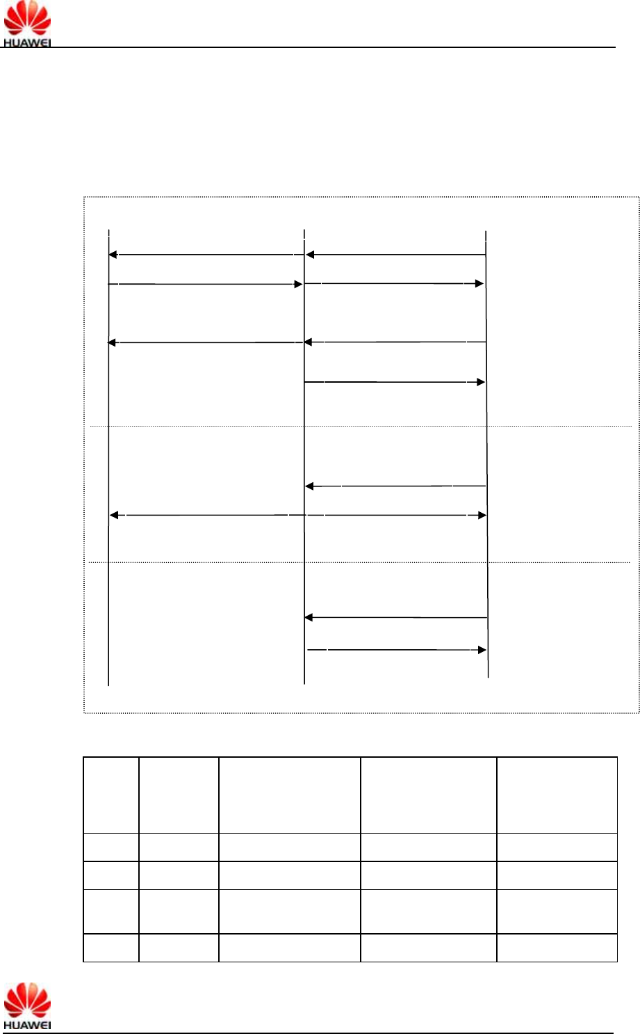
HUAWEI UMTS M2M Module AT Command Interface Specification Confidential
All rights reserved Page 34, Total 96
2 If SMS-DELIVER is stored into MS, indication of the memory location is routed to
the TE.
+CMTI: <mem>,<index>
3 If SMS-DELIVER is stored into MS, SMS-DELIVER indication is not routed to
TE.
In the above three modes, the interaction between TE and MS is shown in the
following diagram.
The relationship between the parameter value of <mt> and the mode of storing and
notifying various messages is shown in the following table.
<mt> no class
or class 1
class 0 or message
waiting indication
group (discard)
class 2 or
message waiting
indication group
(store)
class 3
0
1 +CMTI [+CMTI] +CMTI +CMTI
2 +CMT &
+CNMA +CMT [& +CNMA] +CMTI +CMT & +CNMA
3 +CMTI [+CMTI] +CMTI +CMT & +CNMA
TE MS NETWORK
Direct reporting (+CMT)
新
Acknowledge (+CNMA) RP-ACK
新
New message
Network timeout
RP-ERROR
Not acknowledged in
a certain time
Store the message
into the MS, and report
the storage position
(+CMTI) RP-ACK
RP-ACK
新
Store the message
into the MS, without
reporting notification
1. Send the
message to the TE
directly. If no
acknowledgement
is received in a
certain time period,
RP-ERROR will be
sent to the network.
2. Store the
message into the
MS, send RP-ACK
to the network, and
report the storage
position
3. Store the
message into the
MS, send RP-ACK
to the network,
without reporting
notification.
Direct reporting (+CMT)
HUAWEI UMTS M2M Module AT Command Interface Specification Confidential
All rights reserved Page 35, Total 96
Note:
The class of message is given by the TP-DCS domain of the message. For details,
see the DCS parameter description of the “+CMGS” command.
+CMT & +CNMA means requiring TE to send a confirmation (+CNMA).
<bm>: For use of setting the cell broadcast information. It is not supported currently.
<ds>: For use of setting the message acknowledgement.
0 Do not send message acknowledgement to the TE.
1 Do not store message acknowledgement in MS, route message
acknowledgement directly to TE.
+CDS: <length><CR><LF><pdu>
2 If the message acknowledgement is stored in the MS, a storage position
notification will be sent to the TE via “+CDSI”.
+CDSI: <mem>,<index>
<bfr>: For use of setting buffer processing after transition from <mode>=0 to
<mode>=1, 2.
0 After entering the <mode>1-2, the buffered unsolicited result codes will be sent
to the TE at a time.
1 After entering the <mode>1-2, the buffered unsolicited result codes will be
emptied.
4.7.4 Informative Examples
For example, set CNMI=1,1,0,1,0.
It indicates that the new class1 messages will be stored in the MS first, and the
storage position will be reported (+CMTI: ME,1}; the message state reports will be
reported directly (+CDS: ).
When it is impossible to report the message notification (e.g. when in the online data
mode), the message notification will be discarded.
4.8 Delete Message +CMGD
4.8.1 Command Syntax
Command Possible response(s)
+CMGD=<index>[,<delfla
g>]
<CR><LF>OK<CR><LF>
In case of SMS-related error:
<CR><LF>+CMS ERROR: <err><CR><LF>
+CMGD=?
<CR><LF>+CMGD: (list of supported <index>s)[,(list of
supported
<delflag>s)]<CR><LF><CR><LF>OK<CR><LF>
4.8.2 Description
EXECUTION command deletes message from memory <mem1> location <index>.
For the setting of <mem1> and description, see the “+CPMS command”. If the second
HUAWEI UMTS M2M Module AT Command Interface Specification Confidential
All rights reserved Page 36, Total 96
parameter <delflag> is present and not set to 0 then the ME shall ignore <index> and
follow the rules for <delflag> shown below. If deleting fails, +CMS ERROR: <err> is
returned.
TEST command returns the valid memory locations and the supported values of
<delflag>.
The TEST command returns the storage position where the message is currently
stored, and the supported <delflag> values.
4.8.3 Defined Values
<index>: Storage position of message
<delflag>:
0 (or default) Delete the messages specified by <index>.
1 Delete all read messages from preferred message storage, leaving unread
messages stored mobile originated messages (whether sent or not) untouched.
2 Delete all read messages from preferred message storage and sent mobile
originated messages, leaving unread messages and unsent mobile originated
messages untouched.
3 Delete all read messages from preferred message storage, sent and unsent
mobile originated messages leaving unread messages untouched.
4 Delete all messages from preferred message storage including unread
messages.
4.9 New Message Acknowledgement to +CNMA
4.9.1 Command Syntax
Command Possible response(s)
+CNMA[=<n>[,<length>[<CR
>
PDU is given<ctrl-Z/ESC>]]]
<CR><LF>OK<CR><LF>
In case of SMS-related error:
<CR><LF>+CMS ERROR: <err><CR><LF>
+CNMA=? <CR><LF>+CNMA: (list of supported
<n>s)<CR><LF><CR><LF>OK<CR><LF>
4.9.2 Description
EXECUTION command confirms reception of a new message which is routed directly
to the TE. This acknowledgement command shall be used when +CSMS parameter
<service> equals 1. For the usage of this command, see also description of “+CNMI”
command.
In PDU mode, it is possible to send either positive (RP-ACK) or negative (RP-ERROR)
acknowledgement to the network. Parameter <n> defines which one will be sent.
Optionally, an acknowledgement TPDU (SMS-DELIVER-REPORT for RP-ACK or
RP-ERROR) may be sent to the network. The entering of PDU is done similarly as
specified in command Send Message +CMGS, except that the format of <ackpdu> is
used instead of <pdu>. PDU shall not be bounded by double quotes.
MS shall not send another +CMT or +CDS result code to TE before previous one is
acknowledged.
HUAWEI UMTS M2M Module AT Command Interface Specification Confidential
All rights reserved Page 37, Total 96
If ME does not get acknowledgement within required time (network timeout), ME
should send RP-ERROR to network, and should shall automatically disable routing to
TE by setting both <mt> and <ds> values of +CNMI to zero.
To make the MS report the message notification again, you need to set <mt> and <ds>
again.
If the command is executed but no message is available for confirmation, the “+CMS
ERROR” will be returned: <err>
The TEST command returns the supported <n> values. If only 0 is supported, it
indicates that the command does not support TPDU sending.
4.9.3 Defined Values
<n>:
0 This option is not supported currently.
1 If the sending is successful, acknowledge with “RP-ACK (or receiving buffered
result code successfully).
2 If the sending is unsuccessful, acknowledge with “RP-ERROR”.
<ackpdu> description:
Basic elements:
Abbr Reference
P1) P2) Description
TP-MTI TP-Message Type Indicator M 2b TP-message type
TP-UDHI TP-User-Data-Header-Indication O b Indicate that TP-UD has a
header
TP-PI TP-Parameter-Indicator M o Indicate which optional
parameters exist
TP-PID TP-Protocol-Identifier O o Protocol ID
TP-DCS TP-Data-Coding-Scheme O o Data coding scheme
TP-UDL TP-User-Data-Length O o User data length
TP-UD TP-User-Data O 3) User data
Note:
1) Whether it is mandatory or optional: Mandatory (M) or Optional (O).
2) Indicates: Integer (I), Bit (b), 2 bits (2b), octet (o).
3) Depends on TP-DCS.
Table 2 Bit number
Number
of Octets 7 6 5 4 3 2 1 0
1 TP-MTI, TP-UDHI
1 TP-PI
0,1 TP-PID
0,1 TP-DCS

HUAWEI UMTS M2M Module AT Command Interface Specification Confidential
All rights reserved Page 38, Total 96
0,1 TP-UDL
0 to 159 TP-UD
The 7th bit and bits 2~5 of the first byte are not used in SMS-DELIVER-REPORT, and
the sender should set them to 0. If any bit of them is not 0, the receiver should ignore
them.
Description:
<TP-MTI>: TP-message type. Bits 0 and 1 in the first byte.
bit1 bit0 Message type
0 0 SMS-DELIVER (in the direction SC to MS)
0 0 SMS-DELIVER REPORT (in the direction MS to SC)
1 0 SMS-STATUS-REPORT (in the direction SC to MS)
1 0 SMS-COMMAND (in the direction MS to SC)
0 1 SMS-SUBMIT (in the direction MS to SC)
0 1 SMS-SUBMIT-REPORT (in the direction SC to MS)
1 1 Reserved
< TP-UDHI >: Indicates that TP-UD has a header. It is located in bit 6 in the first byte.
0 TP-UD domain contains only messages.
1 The beginning of TP-UD domain has a header.
< TP-PI >: Indicates which optional parameters exist. If the bit is set as 1, it means no
corresponding parameter exists.
bit 7 bit 6 bit 5 bit 4 bit 3 bit 2 bit 1 bit 0
Extension
bit
Reserved Reserved Reserved Reserved TP-UDL TP-DCS TP-PID
<TP-PID>: Protocol ID. The default value set by TE when sending the message is
00000000. If the transmitting address is an E-mail, the TE should fill in
00110010=0x32.
<TP-DCS>: While sending the message, the TE selects the TP-DCS mode.
0If TE sets bit5 to be 0, it indicates no
message is compressed.
bit5
1
If bit5 is 1, it indicates the sent message is
compressed, and TE does not select this
value.
0If TE sets bit4 to be 0, it indicates that bit1
and bit0 are reserved, and the value is 00.
bit4
1
If bit4 is 1, it indicates that bit1 and bit0 have
the meaning of message type (The message
type depends on the user’s settings. If the
message type is set by the user, TE sets bit4
to be 1, e.g. set class 1 or class 2).
0
0GSM 7 bit default code
bit7~bit6(
while
sending
the
message,
the TE
selects
the
TP-DCS
mode)
00, while
sending
the
message,
the TE
selects
this
value.
bit3~2
(message
code
format) 0
18bit data
HUAWEI UMTS M2M Module AT Command Interface Specification Confidential
All rights reserved Page 39, Total 96
1
0
UCS2 code mode. When the user inputs
Chinese characters, the TE will select this
value.
0
0
Class 0, provided to the interface to display
and reply that the SC has received but not
stored it.
0
1
Class 1, stored to the MS (i.e., NV), or stored
to the SIM card when the MS is full
1
0
Class 2, for special use of SIM. After the
message is stored, the storage state will be
replied to the SC. If the SIM card is full, the
SC failure and the reasons will be reported.
bit1~0
(message
type, its
value is
selected
by TE
according
to the
user’s
options) 1
1
Class 3, stored to the TE. When the MS
receives the message, but has not
transmitted it to the TE, it will give a
response to the SC.
0
The message wait prompt function is invalid.
Currently, the functions that require
prompting, e.g. enforcement message,
E-mail and voice mail, are not supported.
bit3
1Activate the message waiting prompt
function
bit2 0 Reserved bits, which make no sense.
0
0With voice message waiting.
0
1With fax message waiting.
1
0With E-mail message waiting.
1100 and
1101
(GSM 7
bit code),
1110
(uncompr
essed
UCS2
code)
bit1~0
(message
waiting
type)
1
1Message waiting of other unknown types
bit3 0 Reserved bits, which make no sense.
0 7bit code
bit2
1 8bit data
0
0
Class 0, providing display and reply to SC
that the message is received but not stored.
0
1
Class 1, stored to the MS (i.e., NV), or stored
to the SIM card
bit7~4
(while
sending
the
message,
the TE
does not
select this
TP-DCS
mode)
1111 (TE
does not
select
this value
either)
bit1~0
1
0
Class 2, for use of SIM only. After storing it,
the storage state is returned to the SC.
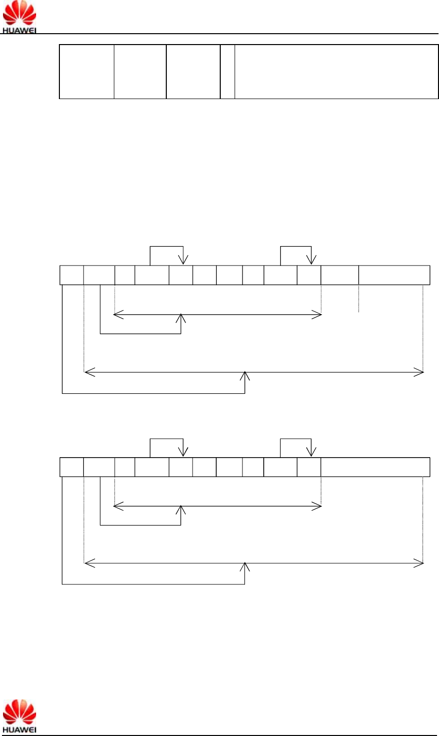
HUAWEI UMTS M2M Module AT Command Interface Specification Confidential
All rights reserved Page 40, Total 96
1
1
Class 3, stored to the TE. When the MS
receives the message, but has not
transmitted it to the TE, it will give a
response to the SC.
<TP-UDL>: Number of bytes occupied by the “user data” domain. If the value is 0, the
“User data” domain does not exist.
<TP-UD>: The “user data” domain may include “user data header”. If it includes the
header (namely, the value of bit6 in byte0 is 1), the value of TP-UDL is equal to the
length filled in the “User-Data-Header” plus the length of “User-Data”. The value of
TP-UDL depends on the specific coding mode. If it is a 7-bit default code, it indicates
that there are a total of how many septets; if it is a 8-bit code, it indicates there are a
total of how many Octets; if it is a UCS2 code, the TP-UDL still means a total of how
many Octets; if there are compressed 7-bit or 8bit or UCS2 codes, the TP-UDL
indicates there are a total of how many Octets after compression. The specific
representation structure in the “User data” domain is shown in the following diagram:
UDL UDHL IEIa IEDa IEIb ......... IEIn IEDLn IEDn Fill bits SM (7bit data)
Septet Boundary
Total number of Octets
Length Indicator
Total number of Septets
Length Indicator
Octets
Octets
IEIDLa
Format of User data of the default 7bit code
UDL UDHL IEIa IEDa IEIb ......... IEIn IEDLn IEDn
Octet Boundary
Total number of Octets
Length Indicator
Total number of Octets
Length Indicator
Octets
Octets
IEIDLa
SM (8 bit data
or UCS-2 data)
Format of User data of 8bit code or UCS2 code
The above two diagrams show the format of filling in the User data, where IEI means
“Information Element Identifier”.
4.10 Message storage selection +CPMS
4.10.1 Command Syntax

HUAWEI UMTS M2M Module AT Command Interface Specification Confidential
All rights reserved Page 41, Total 96
Command Possible response(s)
+CPMS=<mem1>[,
<mem2>[,<mem3>]]
<CR><LF>+CPMS:
<used1>,<total1>,<used2>,<total2>,<used3>,<total3><
CR><LF><CR><LF>OK<CR><LF>
In case of MS-related error:
<CR><LF>+CME ERROR: <err><CR><LF>
+CPMS?
+CPMS:
<mem1>,<used1>,<total1>,<mem2>,<used2>,<total2>,
<mem3>,<used3>,<total3><CR><LF><CR><LF>OK<
CR><LF>
In case of MS-related error:
<CR><LF>+CME ERROR: <err><CR><LF>
+CPMS=?
+CPMS: (list of supported <mem1>s),(list of supported
<mem2>s),
(list of supported
<mem3>s)<CR><LF><CR><LF>OK<CR><LF>
4.10.2 Description
The SET command is used to set the message storage media corresponding to the
message read/write operations, and return the current use state of the selected media.
The READ command returns the name and use state of the currently selected media.
The TEST command returns all the media types supported by the MS.
4.10.3 Defined Values
<mem1>:
String value. It indicates the media for use of reading and deleting messages. Optional
values are:
“SM”, which means the (U)SIM card.
<mem2>:
String value. It indicates the media for use of writing and sending messages. The
optional values are the same as those of <mem1>.
<mem3>:
String value. It indicates the media for use of storing the received message. The
optional values are the same as those of <mem1>.
<total1>:
Integer value. It indicates the total number of messages that can be saved in <mem1>.
<total2>:
Integer value. It indicates the total number of messages that can be saved in <mem2>.
<total3>:
Integer value. It indicates the total number of messages that can be saved in <mem3>.
<used1>:
Integer value. It indicates the total number of messages currently stored in <mem1>.
<used2>:
HUAWEI UMTS M2M Module AT Command Interface Specification Confidential
All rights reserved Page 42, Total 96
Integer value. It indicates the total number of messages currently stored in <mem2>.
<used3>:
Integer value. It indicates the total number of messages currently stored in <mem3>.
4.11 Reporting message storage media being full
%SMMEMFULL
4.11.1 Command Syntax
Command Possible response(s)
<CR><LF>%SMMEMFULL:<mem_type><CR><LF>
4.11.2 Description
When the message storage media overflow, the event will be reported automatically.
4.11.3 Defined Values
<mem_type>:
String value. It indicates the type of the overflowing media.
“SM”, which means the (U)SIM card. (Status will not be reported because of the
custom-built requirement of Maxon. The oldest message which stored in SM will be
replaced by the new message automatically if SM is full. So there is no
“SMMEMFULL” report.)
“ME”, which means NV
4.12 SMSC number command +CSCA
4.12.1 Command Syntax
Command Possible response(s)
+CSCA=<sca>[,<tosca>]
<CR><LF>OK<CR><LF>
In case of MS-related error:
<CR><LF>+CME ERROR: <err><CR><LF>
+CSCA?
<CR><LF>+CSCA:
<sca>,<tosca><CR><LF><CR><LF>OK<CR><LF>
In case of MS-related error:
<CR><LF>+CME ERROR: <err><CR><LF>
+CSCA=? <CR><LF>OK<CR><LF>
4.12.2 Description
The SET command is used to set the SMSC number. For the message in the PDU
mode, the setting of this command can be used only if the SMSC-related parameter
HUAWEI UMTS M2M Module AT Command Interface Specification Confidential
All rights reserved Page 43, Total 96
sc_len has the value of 0 (for the PDU format, see the “+CMGS” command) in the
PDU.
4.12.3 Defined Values
<sca>:
String value. It indicates the SMSC number. The number is composed “*”, “#” and
“0”-“9”. The number contains 20 characters at most.
<tosca>:
Integer value. It indicates the number type, where “145” means an international call.
For the specific values, see also the definition of the “type_addr” parameter in the SC
number, as described in the section “Short message sending +CMGS”.
If no <tosca> parameter is included, it is equivalent to the effect that the <tosca>
parameter is not modified.
4.13 Message sending +CMGS
4.13.1 Command Syntax
Command Possible response(s)
+CMGS=<length><CR>
PDU is given<ctrl-Z/ESC>
<CR><LF>+CMGS:
<mr>[,<ackpdu>]<CR><LF><CR><LF>OK<CR><LF>
In case of SMS-related error:
<CR><LF>+CMS ERROR: <err><CR><LF>
+CMGS=? <CR><LF>OK<CR><LF>
4.13.2 Interface Description
Send a message to the network side. The process of sending a message includes two
steps:
First, deliver “+CMGS=<length>” ended with (CR).
After MS returns <CR><LF><greater_than><space>(IRA 13, 10, 62, 32), the TE
delivers the PDU packet, which is ended with <ctrl-Z>(IRA 26).
4.13.3 Defined Values
<length>: The number of actually sent TPDU characters/2. The digits are decimal
numbers that range from 0 to 9. The maximum value is 178.
<mr>: Message ID. The digits are decimal numbers that range from 0 to 9. The value
range is: 0~255
<ackpdu>: When the value of <service> in “+CSMS” is 1, which is supported by the
network, this field will be returned. Unless no SCA exists, the format is the same as the
format of PDU. This field is not supported currently.
<ctrl-Z>: Identifies the end of a PDU data. The characters are: '0x1A'
<ESC>: Cancels the sending of this message. The characters are: '0x1B'
The structure of the PDU packet is as follows: (The values of the characters described
in the packet are: 0~9, A~F, a~f. Two characters make up one Octet value. for
example: ’23’=0x23, ‘2a’=0x2a, all are hexadecimal}
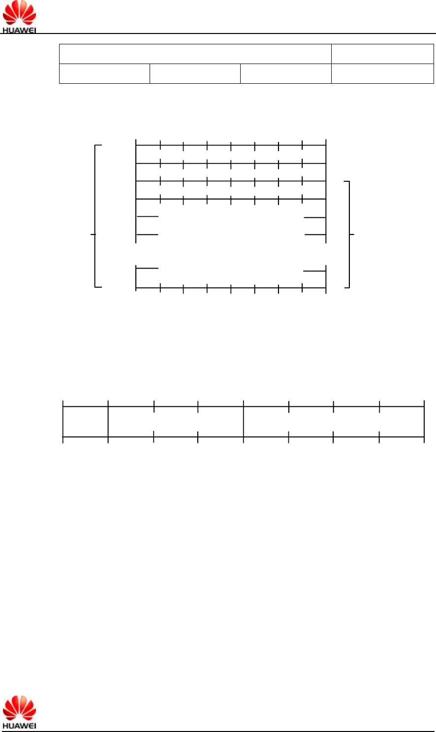
HUAWEI UMTS M2M Module AT Command Interface Specification Confidential
All rights reserved Page 44, Total 96
[<SCA>]
<sc_len> <type_addr> <numbers> TPDU
<SCA> SMSC address. Its structure is as follows:
Address-Length
Type-of-Address
Address-Value
Addr.
.
.
................................
1
2
3
4
5
µ
.
.
<sc_len>: Length of the SCA (short message service center number). It is composed
of two characters. It indicates the number of characters occupied by <type_addr> and
<numbers>/2.
<type_addr>: Number address type. It is composed of two characters. Its structure is
as follows:
Type-of-number Numbering-plan-identification
1
Type-of-Number(bit6…bit4). The values are as follows:
0 0 0 This value is written when the user does not know the authentication
information of the target address number. In this case, the address number is
organized at the network side.
0 0 1 This value is selected if the user knows that it is an international number,
or believes that it falls in the domestic range.
0 1 0 Domestic number. No prefix or suffix is allowed. This value is selected
when the user sends a message to a domestic telephone set.
0 1 1 A specific number in this network. It is used for management or service
and cannot be selected by the user.
1 0 1 The number type is the default 7bit code mode of GSM. It is not in use
currently.
1 1 0 Short number. It is not in use currently.
1 1 1 Reserved for extension. It is not in use currently.
Numbering-plan-identification(bit3…bit0). The values are as follows:
(Note: It is valid only when the values of bit6…bit4 are 000, 001, 010. In other
circumstances, bit3…bit0 are not valid)
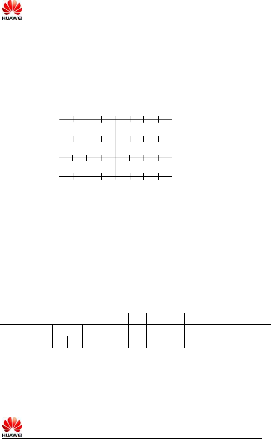
HUAWEI UMTS M2M Module AT Command Interface Specification Confidential
All rights reserved Page 45, Total 96
0 0 0 0 The number is determined by the numbering plan at the network side.
0 0 0 1 ISDN/telephone numbering plan.
0 0 1 1 Data numbering plan, not in use currently.
0 1 0 0 Telex numbering plan, not in use currently.
1 0 0 0 National numbering plan, not in use currently.
1 0 0 1 Private numbering plan, not in use currently.
1 0 1 0 ERMES numbering plan, not in use currently.
<numbers>: Address number. One byte contains two digits. Bit3~bit0 contain the first
digit, and bit7~bit4 contain the second digit. Coding sequence of half bytes, as shown
in the following example:
Digit 2
Digit 1
Digit 4 Digit 3
Digit 5
n+1
n+2
n+3 1
1
1
1
Figure 2 Half byte coding with a total of 5 digits
Note: If the number length is an odd number, the highest four digits of this octet should
be filled with 1111.
‘*’: 1010 ‘#’: 1011
‘a’: 1100 b’: 1101 ‘c’: 1110
For example:
If the number of SCA is 13902900, then the <numbers> is: 31099200
If the number length of SCA is an odd number: 139029001, then <numbers> is:
31099200F1
If the number type is: ‘A1’, the corresponding <SCA> will be 05a131099200.
If the type is indicated as an international number ‘A1’, while the number 13902900
is a domestic number, it is necessary to additionally dial 86 before the number, hence
the corresponding <SCA> in this case is 06a16831099200.
The data structure of TPDU is as follows:
1Octet 1Oct 2Oct~12Oct 1Oct 1Oct 1Oct 1Oct
RP UDHI SRR VPF RD MTI MR DA PID DCS VP UDL UD
Bit7 Bit6 Bit5 Bit4 Bit3 Bit2 Bit1 Bit0
<MTI>: Message type. The values are as follows:
bit1 bit0
0 0 SMS-DELIVER (in the direction SC to MS)
0 0 SMS-DELIVER REPORT (in the direction MS to SC)
1 0 SMS-STATUS-REPORT (in the direction SC to MS)
1 0 SMS-COMMAND (in the direction MS to SC)

HUAWEI UMTS M2M Module AT Command Interface Specification Confidential
All rights reserved Page 46, Total 96
0 1 SMS-SUBMIT (in the direction MS to SC)
0 1 SMS-SUBMIT-REPORT (in the direction SC to MS)
1 1 Reserved
<RD>: It indicates whether the SC needs to receive the short message that is still
stored in the SC and has the MR and DA identical with those of the message sent
previously from the same OA. The values are as follows:
0 To receive
1 Not to receive
<VPF>: It indicates the validity of the VP field and the format. The values are as
follows:
bit4 bit3
0 0 The VP field is invalid
1 0 The VP field is valid and the format is “relative”. Only this format is available
currently.
0 1 The VP field is valid, and the format is “enhanced”.
1 1 The VP field is valid, and the format is “absolute”.
<RP>: Indicates the setting of the path of the message reply. The values are as
follows:
0 No setting.
1 Settings are available. It indicates that the reply has the SC number settings
identical with those of the message, and the return path is the same.
<UDHI>: Indicates the user data header. The values are as follows:
0 The user data segment contains only contents of the message.
1 In addition to the message, the user data segment contains a data header.
<SRR>: State report request indication
0 State report information about successful sending of a message is not required.
1 State report information about successful sending of a message is required.
<MR>: Message ID. Value range: 0~255.
<DA>: DA (destination address), same as defined in SCA. There are a total of
2~12Otects. Therefore, the longest address in the DA segment contains 20 digits.
<PID>: Protocol indication. The values are as follows:
PID
Bit7 Bit6 Bit5 Bit4 Bit3 Bit2 Bit1 Bit0
Bit7 bit6 (here we assume bit 7 = 0 and bit 6 = 0)
0 0 Allocate bits 0..5. The values are defined below.
1 0 Allocate bits 0..5. The values are defined below.
0 1 Reserved.
1 1 Allocate bits 0..5, for special purpose of SC.
The values of Bit5 are as follows:
0 no interworking, but SME-to-SME protocol
1 telematic interworking (in this case, the values of bits 4...0 are valid)
Bit4...bit0 telematic devices type indication:
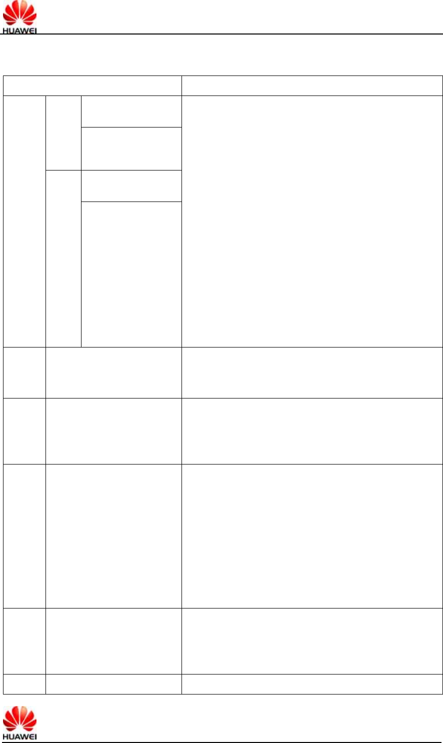
HUAWEI UMTS M2M Module AT Command Interface Specification Confidential
All rights reserved Page 47, Total 96
If the values are 1 0 0 1 0, it indicates Email. Other values are not supported currently.
<DCS>: Coding mode of user data. The values are as follows:
Bit7…bit4 Bit3…..bit0
0: Message is not
compressed
Bit5 1: Message is
compressed. Not
supported currently.
0: Bit1 and bit0 are
reserved
00xx
Bit4 1: Bit1 and bit0
indicate message
type
Bit1 bit0 indicate message type
0 0 : Class 0, providing display and reply to the SC
that the message is received but not stored.
0 1 : Class 1, stored to the NV (or SIM card if the
NV is full)
1 0 : Class 2, for use of SIM only. After the
message is stored, the storage state will be replied to the
SC. If the SIM card is full, the SC failure and the reasons
will be reported.
1 1 : Class 3, stored to the TE. When the MS
receives the message, but has not transmitted it to the
TE, it will give a response to the SC.
Bit3 bit2 message type indication
0 0 : GSM 7 bit default code
0 1 : 8bit data
1 0 : UCS2 code mode. When the user inputs
Chinese characters, this value will be selected.
1 1 : Reserved.
0100
…
1011
Reserved.
1100
The message contents are
discarded. The message
waiting prompt is given, and
the user data adopts GSM 7
bit coding
The settings of Bit3…0 are identical with the settings
made in case of bit7…4=1101
1101
The message is stored. The
message waiting prompt is
given, and the user data
adopts GSM 7 bit coding
Bit3 Prompt indication. The values are as follows:
0: The message waiting prompt function is invalid
1: Activate the message waiting prompt function
Bit2 Reserved. The value is 0.
Bit1 bit0 message type indication
0 0 : With voice message waiting.
0 1 : With fax message waiting.
1 0 : With E-mail message waiting.
1 1 : Message waiting of other unknown types
1110
The message is stored. The
message waiting prompt is
given, and the user data
adopts uncompressed UCS2
coding
The settings of Bit3…0 are identical with the settings
made in case of bit7…4=1101
1111 Data coding/message class Bit2 Reserved. The value is 0.

HUAWEI UMTS M2M Module AT Command Interface Specification Confidential
All rights reserved Page 48, Total 96
Bit2 Coding mode of message. The values are as
follows:
0: GSM 7 bit default code
1: 8bit data
Bit1 bit0 message type indication
0 0 : Class 0, providing display and reply to the SC
that the message is received but not stored.
0 1 : Class 1, stored to the NV (or SIM card if the
NV is full)
1 0 : Class 2, for use of SIM only. After the
message is stored, the storage state will be replied to the
SC. If the SIM card is full, the SC failure and the reasons
will be reported.
1 1 : Class 3, stored to the TE. When the MS
receives the message, but has not transmitted it to the
TE, it will give a response to the SC.
<VP>: Indicates the validity period, which starts from the message being received by
the SC. If VPF=00, this field is lacking. The duration is expressed as follows:
VP value Description
0 to 143 (VP + 1) x 5 minutes
144 to 167 12 hours + ((VP -143) x 30 minutes)
168 to 196 (VP - 166) x 1 day
197 to 255 (VP - 192) x 1 week
<UDL>: Length of user data. The value of UDL depends on the specific coding mode.
In case of default 7-bit coding, it indicates there are a total of how many septets.
In case of 8bit coding, it indicates there are a total of how many Octets.
In case of UCS2 coding, UDL indicates there are a total of how many Octets.
In case of compressed 7-bit or 8bit or UCS2 coding, UDL indicates there are a total of
how many Octets after compression.
For the compressed message codes, the data length of <UD> should not be more
than 160septets; for the message of uncompressed codes, the <UD> length should
not be more than 140Octets.
<UD>: User data. The data validity depends on the parameter UDL.
4.13.4 Examples
The SMSC number is: 13902900, and the message is sent to the number:
13901000453, and the contents are: 0x53 0x4E 0x4E 0x3A (“华为” for UCS2 encode),
then:
If “+CSCA” has set SCA, then
a) When sending the message, the <SCA> field can be left uncompleted. The
<SCA> value is obtained through the value set via “+CSCA” command.

HUAWEI UMTS M2M Module AT Command Interface Specification Confidential
All rights reserved Page 49, Total 96
AT+CMGS=17(CR)
>81000B813109010054F3001804534E4E3A \x1A
Note: Data interpretation, 81(<RP~MTI>)00(<MR>)0B(<DA-len>)81(<DA-type>)
3109010054F3(<DA-numbers>)00(<PID>)18(<DCS>)04(<UDL>)534E4E3A
(<UD>)\x1A(<ctrl-Z>)
b) When sending the message, the <SCA> field can also be completed, and the
<SCA> value can be obtained directly from the PDU packet.
AT+CMGS=17
>05a13109920081000B813109010054F3001804534E4E3A \x1A
or
AT+CMGS=17
>0081000B813109010054F3001804534E4E3A \x1A
(In this case, since <sc_len>=0,when sending the message, the <SCA> can be
obtained through the value set via the “+CSCA” command)
If “+CSCA” has not set SCA, then
When sending the message, the <SCA> field must be completed, and the <SCA>
value can be obtained directly from the PDU packet.
AT+CMGS=17
>05a13109920081000B813109010054F3001804534E4E3A \x1A
4.14 Message storage command +CMGW
4.14.1 Command Syntax
Command Possible response(s)
+CMGW=<length>[,<stat>]<C
R>PDU is given<ctrl-Z/ESC>
<CR><LF>+CMGW:
<index><CR><LF><CR><LF>OK<CR><LF>
In case of SMS-related error:
<CR><LF>+CMS ERROR: <err><CR><LF>
+CMGW=? <CR><LF>OK<CR><LF>
4.14.2 Interface Description
Store a message to the <mem2> storage set via the “+CPMS” command.
4.14.3 Defined Values
<length>: Number of actually sent TPDU characters/2.
<mr>: Message ID. The digits are decimal numbers that range from 0 to 9. The value
range is: 0~255.
<ctrl-Z>: Identifies the end of a PDU data. The characters are: '0x1A'
<ESC>: Cancels the sending of this message. The characters are: '0x1B'

HUAWEI UMTS M2M Module AT Command Interface Specification Confidential
All rights reserved Page 50, Total 96
<stat>: Storage state of the message. The values are as follows: (In the PDU mode,
the default value is 0)
0 Unread message that has been received
1 Read message that has been received
2 Unsent message that has been stored
3 Sent message that has been stored
4 Any message (This value is only applicable to the “+CMGL” command)
<index>: Position number in the storage. The digits are decimal numbers that range
from 0 to 9. The value range is 0~maximum capacity of storage-1.
The PDU packet structure is consistent with the description of the “+CMGS”
command.
4.15 Message list command +CMGL
4.15.1 Command Syntax
Command Possible response(s)
+CMGL[=<stat>]
In case of pdu mode and successful execution of command:
[<CR><LF>+CMGL:
<index>,<stat>,[<reserved>],<length><CR><LF><pdu>
[<CR><LF>+CMGL:<index>,<stat>,[<reserved>],<length><CR
><LF><pdu>
[...]]<CR><LF>]<CR><LF>OK<CR><LF>
Otherwise:
<CR><LF>+CMS ERROR: <err><CR><LF>
+CMGL=? <CR><LF>+CMGL: (list of supported <stat>s)
<CR><LF><CR><LF>OK<CR><LF>
4.15.2 Description
The EXECUTION command returns all messages from <mem1>, which are in the
state specified by the parameter <stat>. If the message state is “Unread message that
has been received”, the state of the message in the storage will be converted to “Read
message that has been received” after the command is executed successfully.
When the <stat> takes on the default value, the EXECUTION command is equivalent
to the SET command +CMGL=0.
The TEST command returns all the supported stat values.
4.15.3 Defined Values
PDU mode:
<stat> Message type. The default value is 0:
0 Unread messages that has been received
1 Read message that has been received
2 Unsent message that has been stored
3 Sent message that has been stored

HUAWEI UMTS M2M Module AT Command Interface Specification Confidential
All rights reserved Page 51, Total 96
4 Any message
<index>: Integer value, which indicates the position in the storage.
<reserved>: Reserved.
<length>: Integer value, which indicates the number of bytes of TPDU data.
<pdu>: Protocol data unit. The data structure is as follows:
[<SCA>]
<sc_len> <type_addr> <numbers> TPDU
Where, the <SCA>, <sc_len>, <type_addr>, and <numbers> fields are defined in the
same way as in the section “Message sending command”.
For sent message, the data structure of TPDU is the same as defined in “Message
sending command”. For the received message, the data structure of TPDU is as
follows:
1 Oct 2 Oct~12
Oct 1 Oct 1 Oct 7 Oct 1Oct
TP-MTI MMS 0 0 SRI UDHI RP OA PID DCS SCTS UDL UD
Bit0 Bit1 Bit2 Bit3 Bit4 Bit5 Bit6 Bit7
<MTI>: Same as defined in the section “Message sending command”.
<MMS>: Indicates whether there are more messages to be sent.
0 Nonexistent
1 Existent
<SRI>: Indicates whether the SME (short message entity) has requested a state
report.
0 Nonexistent
1 Existent
<UDHI>: Same as defined in the section “Message sending command”.
<RP>: Same as defined in the section “Message sending command”.
<OA>: Source address. Same as defined in SCA. Total 2~12Otects. Therefore, the
longest address in the OA segment contains 20 digits.
<PID>: Protocol indication. Same as defined in the section “Message sending
command”.
<DCS>: Coding mode of user data. Same as defined in the section “Message sending
command”.
<SCTS>: Time chop of SMC, including year, month, day, hour, minute, second and
time difference. Time difference refers to the difference of time between the local time
and the Greenwich standard time.
<UDL>: User data length. Same as defined in the section “Message sending
command”.
<UD>: The length of a specific user data depends on the UDL.
Text mode:
<stat> Message type. The default value is 0:
"REC UNREAD" unread SMS

HUAWEI UMTS M2M Module AT Command Interface Specification Confidential
All rights reserved Page 52, Total 96
"REC READ" read SMS
"STO UNSENT" stored and unsent SMS
"STO SENT" stored and sent SMS
"ALL" all SMS
4.16 Read a message +CMGR
4.16.1 Command Syntax
Command Possible response(s)
+CMGR=<index>
In case of pdu mode and successful execution of command:
<CR><LF>+CMGR:
<stat>,[<reserved>],<length><CR><LF><pdu><CR><LF><C
R><LF>OK<CR><LF>
or:
<CR><LF>+CMS ERROR: <err><CR><LF>
+CMGR=? <CR><LF>OK<CR><LF>
4.16.2 Description
The EXECUTION command returns the messages whose storage position is “index”
from <mem1>. If the message state is “Unread message that has been received”, the
state of the message in the storage will be converted to “Read message that has been
received” after the command is executed successfully.
The TEST command returns OK.
4.16.3 Defined Values
<index>: Integer value, which indicates the position in the storage.
<stat> Message type:
0 Unread message that has been received
1 Read message that has been received
2 Unsent message that has been stored
3 Sent message that has been stored
<reserved>: Reserved.
<length>: Integer value, which indicates the number of bytes of PDU data.
<pdu>: Protocol data unit. Its format is the same as defined in section “Message list
command”.
4.17 Message bearer domain command +CGSMS
4.17.1 Command Syntax
Command Possible response(s)
HUAWEI UMTS M2M Module AT Command Interface Specification Confidential
All rights reserved Page 53, Total 96
Command Possible response(s)
+CGSMS=<service> <CR><LF>OK<CR><LF>
+CGSMS? <CR><LF>+CGSMS:<service><CR><LF><CR><LF>OK<C
R><LF>
+CGSMS=? <CR><LF>+CGSMS: (list of supported
<service>s)<CR><LF><CR><LF>OK<CR><LF>
4.17.2 Description
The SET command is used to set the message bearer domain, namely, selection of
CS/PS domain.
The READ command returns the current message bearer domain.
The TEST command returns the supported parameter values.
4.17.3 Defined Values
<service>:
0 Only select the PS domain (not supported currently)
1 Only select the CS domain (not supported currently)
2 Prefer the PS domain
3 Prefer the CS domain
4.18 More Messages to Send +CMMS
4.18.1 Command Syntax
Command Possible response(s)
+CMMS=[<n>] <CR><LF>OK<CR><LF>
+CMMS? <CR><LF>+CMMS:<n><CR><LF><CR><LF
>OK<CR><LF>
+CMMS=? <CR><LF>+CMMS: (list of supported
<n>s)<CR><LF><CR><LF>OK<CR><LF>
4.18.2 Description
Set command controls the continuity of SMS relay protocol link. When feature is
enabled (and supported by network) multiple messages can be sent much faster as
link is kept open.
Test command returns supported values as a compound value.
4.18.3 Defined Values
<n>:
0 disable

HUAWEI UMTS M2M Module AT Command Interface Specification Confidential
All rights reserved Page 54, Total 96
1 keep enabled until the time between the response of the latest message send
command (+CMGS, +CMSS, etc.) and the next send command exceeds 1-5
seconds (the exact value is up to ME implementation), then ME shall close the
link and TA switches <n> automatically back to 0
2 enable (if the time between the response of the latest message send command
and the next send command exceeds 1-5 seconds (the exact value is up to ME
implementation), ME shall close the link but TA shall not switch automatically
back to <n>=0)
I
5 Description of Security Setting Interface
5.1 PIN password modifying +CPWD
5.1.1 Command Syntax
Command Possible response(s)
+CPWD=<fac>,<oldpwd
>,<newpwd>
<CR><LF>OK<CR><LF>
In case of MS-related error:
<CR><LF>+CME ERROR: <err><CR><LF>
+CPWD=?
<CR><LF>+CPWD: list of supported
(<fac>,<pwdlength>)s<CR><LF><CR><LF>OK<CR><L
F>
In case of MS-related error:
<CR><LF>+CME ERROR: <err><CR><LF>
5.1.2 Description
The EXECUTION command is used to modify the equipment lock function (e.g. PIN).
The TEST command returns the supported device, and the maximum length of the
password corresponding to this equipment.
5.1.3 Defined Values
<fac>: Specify the object of operation of this command (only supporting SIM card, the
value is ”SC”).
"SC": SIM card PIN
"P2": SIM card PIN2
“AB”: No support for a while
<oldpwd>,<newpwd>: Old password, new password, string type, and maximum length
are specified by the parameter <pwdlength>.
<pwdlength>: Maximum length of the equipment lock password.
5.2 PIN enabling and query function +CLCK

HUAWEI UMTS M2M Module AT Command Interface Specification Confidential
All rights reserved Page 55, Total 96
5.2.1 Command Syntax
Command Possible response(s)
+CLCK=<fac>,<mode>[,
<passwd>[,<class>]]
In case of <mode>=2 and successful execution of
command:
<CR><LF>+CLCK:
<status><CR><LF><CR><LF>OK<CR><LF>
In case of <mode>≠2 and successful execution of
command:
<CR><LF>OK<CR><LF>
In case of MS-related error:
<CR><LF>+CME ERROR: <err><CR><LF>
+CLCK=? <CR><LF>+CLCK: (list of supported
<fac>s)<CR><LF><CR><LF>OK<CR><LF>
5.2.2 Description
The EXECUTION command is used to lock, unlock and query the MS or network
equipment <fac>. Generally, the password needs to be input.
The TEST command returns the supported devices.
5.2.3 Defined Values
<fac>: Specify the object of operation of this command (only supporting SIM card, the
value is ”SC”).
"SC": SIM card (if this command is configured, the password must be input when
powering on the MS)
<mode>:
0 Unblock
1 Lock
2 Query state
< status >:
0 Unactivated
1 Activated
<passwd>: String type; same as the password set via “modify password +CPWD”.
<classx> (7 by default):
1 Voice call
2 Data
4 Fax
8 SMS
5.3 PIN management command +CPIN
5.3.1 Command Syntax

HUAWEI UMTS M2M Module AT Command Interface Specification Confidential
All rights reserved Page 56, Total 96
Command Possible response(s)
+CPIN=<pin>[,<newpin>]
<CR><LF>OK<CR><LF>
In case of MS-related error:
<CR><LF>+CME ERROR: <err><CR><LF>
+CPIN? <CR><LF>+CPIN:
<code><CR><LF><CR><LF>OK<CR><LF>
+CPIN=? <CR><LF>OK<CR><LF>
5.3.2 Description
The READ command is used to indicate whether password input request exists.
The SET command is used to check and unlock the PIN and PIN2.
If the current password input request is PIN or PIN2, input “+CPIN=<pin>” to check.
If the current password input request is PUK or PUK2, input “+CPIN=<pin>,<newpin>”
to unlock. The first parameter is SIM PUK or SIM PUK2, and the second parameter is
<newpin>, which is a new PIN or PIN2.
When using the SET command, if the no PIN input request exists currently, an error
message “+CME ERROR” will be returned.
Note: Verifying PIN or PUK during an emergency call may make the call disconnected.
5.3.3 Defined Values
<pin>, <newpin>: String
<code>: String (without quotation marks)
READY: MT without password input request
SIM PIN: UICC/SIM PIN password request
SIM PUK: UICC/SIM PUK password request, to unblock the SIM PIN which was
blocked for 3 verification failure.
SIM PIN2: PIN2 password requestSIM PUK2: PUK2 password request, to
unblock the SIM PIN2 which was blocked for 3 verification failure
5.4 SIMLOCK unlocking and query command
%SIMLOCK
5.4.1 Command Syntax
Command Possible response(s)
%SIMLOCK=<mode>[,<p
assword>]
<mode>=0 and executes successfully:
<CR><LF>OK<CR><LF>
<mode>=2 and executes successfully:
<CR><LF>%SIMLOCK:
<status><CR><LF><CR><LF>OK<CR><LF>
Use this in a wrong way:
<CR><LF>ERROR<CR><LF>
HUAWEI UMTS M2M Module AT Command Interface Specification Confidential
All rights reserved Page 57, Total 96
Command Possible response(s)
% SIMLOCK =?
<CR><LF>%
SIMLOCK:(0,2),"password(6~8)”<CR><LF>
<CR><LF>OK<CR><LF>
5.4.2 Interface Description
This command is used to unlock simlock function and query if enable simlock or not. If
user inputs wrong password three times continuously, module will be reset.
5.4.3 Defined Values
<mode>:
0: Unlock simlock function.
2: Query simlock state.
<password>: A string is combined by 6~8 numbers, these numbers must be digits 0~9.
If it’s the permanent password, the length of password will be 8 numbers only.
Password is effective when mode sets to be 0.
<status>:
0: Disable simlock function.
1: Enable simlock function.
6 System Setting Interface Description
6.1 System information query %SYSINFO
6.1.1 Command Syntax
Command Possible response(s)
%SYSINFO
<CR><LF>%SYSINFO:< srv_status >,< srv_domain >,<
roam_status >,< sys_mode >,< sim_state
>[,<reserved>,<sys_submode>]<CR><LF><CR><LF>
OK<CR><LF>
%SYSINFO? <CR><LF>ERROR<CR><LF>
%SYSINFO=? <CR><LF>ERROR<CR><LF>
6.1.2 Interface Description
This command is used to query the current system information, e.g. system service
state, domain, roaming or not.
6.1.3 Defined Values
<srv_status>: System service state. The values are as follows:
0 No service.

HUAWEI UMTS M2M Module AT Command Interface Specification Confidential
All rights reserved Page 58, Total 96
1 Restricted service
2 Valid service
3 Restricted regional service.
4 Power-saving and deep sleep state
<srv_domain>: System service domain. The values are as follows:
0 No service.
1 Only CS service
2 Only PS service
3 PS+CS service
4 CS and PS not registered, searching
<roam_status>: Roaming status. The values are as follows:
0 Non roaming state
1 Roaming state
<sys_mode>: System mode. The values are as follows:
0 No service.
1 AMPS mode (not in use currently)
2 CDMA mode (not in use currently)
3 GSM/GPRS mode
4 HDR mode
5 WCDMA mode
6 GPS mode
<sim_state>: SIM card state. The values are as follows:
0 Invalid USIM card state or pin code locked
1 Valid USIM card state
2 USIM is invalid in case of CS
3 USIM is invalid in case of PS
4 USIM is invalid in case of either CS or PS
255 USIM card is not existent,
<reserved>:reserved. E618 used it to indicate the simlock state
<sys_submode>:System sub mode, the values are as follows:
0: No service
1: GSM mode
2: GPRS mode
3: EDGE mode
4: WCDMA mode
5: HSDPA mode
6: HSUPA mode
7: HSDPA mode and HSUPA mode
6.2 Service state change indication %SRVST
6.2.1 Command Syntax
HUAWEI UMTS M2M Module AT Command Interface Specification Confidential
All rights reserved Page 59, Total 96
Command Possible response(s)
<CR><LF>%SRVST:<srv_status><CR><LF>
6.2.2 Description
When the service state changes, the MS will report the new service state to the TE.
6.2.3 Defined Values
<srv_status>: System service state. The values are as follows:
0 No service.
1 Restricted service.
2 Valid service
3 Restricted regional service.
4 Power-saving and deep sleep state
6.3 SIM state change indication %SIMST
6.3.1 Command Syntax
Command Possible response(s)
<CR><LF>%SIMST:<sim_state>
6.3.2 Interface Description
When the USIM card state changes, the MS will report the new state to the TE. At the
same time, report the lock state of USIM card.
6.3.3 Defined Values
<sim_state>: USIM card state. The values are as follows:
0 Invalid USIM card state or pin code locked
1 Valid USIM card state
2 USIM is invalid in case of CS
3 USIM is invalid in case of PS
4 USIM is invalid in case of either CS or PS
255 USIM card is not existent,
6.4 System mode change event indication %MODE
6.4.1 Command Syntax
Command Possible response(s)

HUAWEI UMTS M2M Module AT Command Interface Specification Confidential
All rights reserved Page 60, Total 96
<CR><LF>%MODE:<sys_mode>[,<sys_submode>]<C
R><LF>
6.4.2 Interface Description
When the system mode or sub-mode changes, the MS will report this indication to the
TE.
6.4.3 Defined Values
<sys_mode>: System mode. The values are as follows:
0 No service.
1 AMPS mode (not in use currently)
2 CDMA mode (not in use currently)
3 GSM/GPRS mode
4 HDR mode
5 WCDMA mode
6 GPS mode
<sys_submode>: System sub mode. The values are as follows:
0 No service.
1 GSM mode
2 GPRS mode
3 EDEG mode
4 WCDMA mode
5 HSDPA mode
6 HSUPA mode
7 HSDPA mode and HSUPA mode
6.5 RSSI change indication %RSSI
6.5.1 Command Syntax
Command Possible response(s)
<CR><LF>%RSSI: <rssi><CR><LF>
6.5.2 Description
When the change of RSSI is more than 5dBm, the MS will report this indication to the
TE.
6.5.3 Defined Values
<rssi>: Strength of the receiving signal. The values are defined as follows:
0 Equal to or less than -113 dBm
HUAWEI UMTS M2M Module AT Command Interface Specification Confidential
All rights reserved Page 61, Total 96
1 -111 dBm
2...30 -109... -53 dBm
31 Equal to or higher than -51 dBm
99 Unknown or unmeasurable.
6.6 System configuration reference setting
%SYSCFG
6.6.1 Command Syntax
Command Possible response(s)
%SYSCFG=
<mode>,<acqorder>,<band>,<roam
>,<srvdomain>
<CR><LF>OK/ERROR<CR><LF>
% SYSCFG?
<CR><LF>%SYSCFG:<mode>,<acqorder>,<
band>,<roam>,<srvdomain><CR><LF><CR>
<LF>OK<CR><LF>
%SYSCFG=? <CR><LF>OK<CR><LF>
6.6.2 Description
This command is used to set the characteristics such as system mode, GW access
sequence, band, roaming support and domain.
6.6.3 Defined Values
<mode> system mode reference:
2 Automatic search
13 GSM ONLY
14 WCDMA ONLY
16 No change
<acqorder> Network access sequence reference:
0 Automatic search
1 GSM first, WCDMA later
2 WCDMA first, GSM later
3 No change
<band> The band of frequency relate to selection of mode, which is actually up to the
performance of MS. The parameter is HEX string, whose value is as follows or with the
exception of 0x3FFFFFFF and 0x40000000 parameter as combination:
00080000 (CM_BAND_PREF_GSM_850) GSM 850
00000080(CM_BAND_PREF_GSM_DCS_1800) GSM DCS systems
00000100(CM_BAND_PREF_GSM_EGSM_900) Extended GSM 900
00000200(CM_BAND_PREF_GSM_PGSM_900) Primary GSM 900

HUAWEI UMTS M2M Module AT Command Interface Specification Confidential
All rights reserved Page 62, Total 96
00100000(CM_BAND_PREF_GSM_RGSM_900) Railway GSM 900
00200000(CM_BAND_PREF_GSM_PCS_1900) GSM PCS
00400000(CM_BAND_PREF_WCDMA_I_IMT_2000) WCDMA IMT 2000
00800000 (CM_BAND_PREF_WCDMA_II_PCS_1900) WCDMA_II_PCS_1900
04000000 (CM_BAND_PREF_WCDMA_V_850) WCDMA_V_850
<roam> Roaming support:
0 Not supported
1 Roaming is supported
2 No change
<srvdomain> domain setting:
0 CS_ONLY
1 PS_ONLY
2 CS_PS
3 ANY
4 No change
7 Phonebook Service Interface Description
7.1 Phonebook memory selection +CPBS
7.1.1 Command Syntax
Command Possible response(s)
+CPBS=<storage>
[,<reserved>]
<CR><LF>OK<CR><LF>
In case of MS-related error:
<CR><LF>+CME ERROR: <err><CR><LF>
+CPBS?
<CR><LF>+CPBS:
<storage>[,<used>,<total>]<CR><LF><CR><LF>OK<CR><
LF>
In case of MS-related error:
<CR><LF>+CME ERROR: <err><CR><LF>
+CPBS=? <CR><LF>+CPBS: (list of supported
<storage>s)<CR><LF><CR><LF>OK<CR><LF>
7.1.2 Description
The SET command is used to select a phonebook memory. The initial value after
restarting the MS is “SM”. Other phonebook-related commands will be operated by
using the memory selected via this command.

HUAWEI UMTS M2M Module AT Command Interface Specification Confidential
All rights reserved Page 63, Total 96
The READ command returns the currently selected phonebook memory. Optionally,
the number of entries in use and the maximum number of entries should also be
returned.
The TEST command returns the supported phonebook memory types.
7.1.3 Defined Values
<storage> : Phonebook memory type. Currently, only “SM”,”ON”,”EN” are supported.
"SM" SIM/UICC phonebook
“ON” SIM/USIM own numbers (MSISDNs) list
“EN” SIM/USIM emergency number
<reserved>: Reserved.
<used>: Integer value. It indicates the number of entries in use in the currently
selected memory.
<total>: Integer value. It indicates the maximum number of entries in the currently
selected memory.
7.2 8.13 Find phonebook entries +CPBF
7.2.1 command syntax
Comman
d
Possible response(s)
+CPBF=<findtext> [+CPBF:
<index1>,<number>,<type>,<text>[,<hidden
>][[...]
<CR><LF>+CBPF:
<index2>,<number>,<type>,<text>[,<hidden
>]]]
+CME ERROR: <err>
+CPBF=? +CPBF: [<nlength>],[<tlength>]
+CME ERROR: <err>
7.2.2 Description
Execution command returns phonebook entries (from the current phonebook memory
storage selected with +CPBS) which alphanumeric field starts with string <findtext>.
Entry fields returned are location number <indexn>, phone number stored there
<number> (of format <type>), text <text> associated with the number and, if the
selected phonebook supports hidden entries, <hidden> indicating if the entry is hidden.
If listing fails in an MT error, +CME ERROR: <err> is returned. Refer subclause 9.2 for
<err> values.
Test command returns the maximum lengths of <number> and <text> fields. In case
of SIM storage, the lengths may not be available. If MT is not currently reachable,
+CME ERROR: <err> is returned. Refer subclause 9.2 for <err> values.
HUAWEI UMTS M2M Module AT Command Interface Specification Confidential
All rights reserved Page 64, Total 96
7.2.3 Defined values
<index1>, <index2>: integer type values in the range of location numbers of phonebook
memory
<number>: string type phone number of format <type>
<type>: type of address octet in integer format (refer TS 24.008 [8] subclause 10.5.4.7)
<findtext>, <text>: string type field of maximum length <tlength>; character set as
specified by command Select TE Character Set +CSCS
<nlength>: integer type value indicating the maximum length of field <number>
<tlength>: integer type value indicating the maximum length of field <text>
<hidden>: indicates if the entry is hidden or not
0: phonebook entry not hidden
1: phonebook entry hidden
7.3 Read phonebook entries +CPBR
7.3.1 Command syntax
Command Possible response(s)
+CPBR=<i
ndex1>
[,<index
2>]
[+CPBR:
<index1>,<number>,<type>,<text>[,<hidden>][[..
.]
<CR><LF>+CPBR:
<index2>,<number>,<type>,<text>[,<hidden>]]]
+CME ERROR: <err>
+CPBR=? +CPBR: (list of supported
<index>s),[<nlength>],[<tlength>]
+CME ERROR: <err>
7.3.2 Description
Execution command returns phonebook entries in location number range <index1>...
<index2> from the current phonebook memory storage selected with +CPBS. If
<index2> is left out, only location <index1> is returned. Entry fields returned are
location number <indexn>, phone number stored there <number> (of format
<type>), text <text> associated with the number and, if the selected phonebook
supports hidden entries, <hidden> indicating if the entry is hidden. If all queried
locations are empty (but available), no information text lines may be returned. If listing
fails in an MT error, +CME ERROR: <err> is returned. Refer subclause 9.2 for <err>
values.
Test command returns location range supported by the current storage as a compound
value and the maximum lengths of <number> and <text> fields. In case of SIM
storage, the lengths may not be available. If MT is not currently reachable, +CME
ERROR: <err> is returned. Refer subclause 9.2 for <err> values.

HUAWEI UMTS M2M Module AT Command Interface Specification Confidential
All rights reserved Page 65, Total 96
7.3.3 Defined values
<index1>, <index2>, <index>: integer type values in the range of location numbers of
phonebook memory
<number>: string type phone number of format <type>
<type>: type of address octet in integer format (refer TS 24.008 [8] subclause 10.5.4.7)
<text>: string type field of maximum length <tlength>; character set as specified by
command Select TE Character Set +CSCS
<nlength>: integer type value indicating the maximum length of field <number>
<tlength>: integer type value indicating the maximum length of field <text>
<hidden>: indicates if the entry is hidden or not
0: phonebook entry not hidden
1: phonebook entry hidden
7.4 Write phonebook entry +CPBW
7.4.1 command syntax
Command Possible response(s)
+CPBW=[<index>][,<number>[
,<type>[,<text>[,<hidden>]
]]]
+CME ERROR: <err>
+CPBW=? +CPBW: (list of supported <index>s),[<nlength>],(list of
supported <type>s),[<tlength>]
+CME ERROR: <err>
7.4.2 Description
Execution command writes phonebook entry in location number <index> in the
current phonebook memory storage selected with +CPBS. Entry fields written are
phone number <number> (in the format <type>), text <text> associated with the
number and, if the selected phonebook supports hidden entries, <hidden> parameter,
which indicates if the entry is hidden or not. If those fields are omitted, phonebook
entry is deleted. If <index> is left out, but <number> is given, entry is written to the
first free location in the phonebook (the implementation of this feature is manufacturer
specific). If writing fails in an MT error, +CME ERROR: <err> is returned. Refer
subclause 9.2 for <err> values.
Test command returns location range supported by the current storage as a compound
value, the maximum length of <number> field, supported number formats of the
storage, and the maximum length of <text> field. In case of SIM storage, the lengths
may not be available. If MT is not currently reachable, +CME ERROR: <err> is
returned. Refer subclause 9.2 for <err> values. If storage does not offer format
information, the format list should be empty parenthesis
7.4.3 Defined values

HUAWEI UMTS M2M Module AT Command Interface Specification Confidential
All rights reserved Page 66, Total 96
<index>: integer type values in the range of location numbers of phonebook memory
<number>: string type phone number of format <type>
<type>: type of address octet in integer format (refer TS 24.008 [8] subclause 10.5.4.7) ;
default 145 when dialling string includes international access code character "+", otherwise
129
<text>: string type field of maximum length <tlength>; character set as specified by
command Select TE Character Set +CSCS
<nlength>: integer type value indicating the maximum length of field <number>
<tlength>: integer type value indicating the maximum length of field <text>
<hidden>: indicates if the entry is hidden or not
0: phonebook entry not hidden
1: phonebook entry hidden
7.5 Phonebook reading %CPBR
7.5.1 Command Syntax
Command Possible response(s)
%CPBR=<index1>
[,<index2>]
[<CR><LF>%CPBR:
<index1>,<number>,<type>,<text>,<coding>[,<email>][[...]
<CR><LF>%CPBR:
<index2>,<number>,<type>,<text>],<coding>[,<email>]]<CR>
<LF>]<CR><LF>OK<CR><LF>
In case of MS-related error:
<CR><LF>+CME ERROR: <err><CR><LF>
%CPBR=?
<CR><LF>%CPBR: (list of supported
<index>s),[<nlength>],[<tlength>],[<mlenth>]<CR><LF><CR>
<LF>OK<CR><LF>
In case of MS-related error:
<CR><LF>+CME ERROR: <err><CR><LF>
7.5.2 Description
This command returns the phonebook entries between positions index1 and index2 in
the currently selected phonebook memory. If no entry exists between index1 and
index2, the following will be returned:
+CME ERROR: not found
Alternatively, you can input index1 only, and only the phonebook entries in the position
index1 will be returned.
The TEST command returns the position range of the currently selected phonebook
memory, and the maximum length of <number>, <text> and <email>.
7.5.3 Defined Values

HUAWEI UMTS M2M Module AT Command Interface Specification Confidential
All rights reserved Page 67, Total 96
<index1>, <index2>, <index>: Integer value. It indicates the position in the phonebook
memory. The values of index1 and index2 are less than or equal to the “total” field
returned by the “+CPBS?” command.
<number>: String type, telephone number.
<type>: Number type: “145” means an international call. For the specific values, see
also the definition of the “type_addr” parameter in the SC number, as described in the
section “Short message sending +CMGS”.
<text>: String type. It indicates a name. In case coding=1, it indicates that the <text> is
a hexadecimal text value of the original data.
<coding>: Coding scheme. It means the character code of the <text> field, and
specifies the language.
0 GSM 7 bit Default Alphabet
1 RAW mode (namely, upload the <text>in the format of original data).
<email>: String type. It indicates the email address. not supported Currently.
<nlength>: Integer value. It indicates the maximum length of the telephone number.
<tlength>: Integer value. It indicates the maximum length of the name.
<mlength>: Integer value. It indicates the maximum length of the email. (currently not
supported)
7.6 Phonebook writing %CPBW
7.6.1 Command Syntax
Command Possible response(s)
%CPBW=[<index>][,<number>[,<t
ype>[,<text>,<coding>[,email]]]]
<CR><LF>OK<CR><LF>
In case of MS-related error:
<CR><LF>+CME ERROR: <err><CR><LF>
%CPBW=?
<CR><LF>%CPBW: (list of supported
<index>s),[<nlength>],
(list of supported
<type>s),[<tlength>],[<mlength>]<CR><LF><C
R><LF>OK<CR><LF>
In case of MS-related error:
<CR><LF>+CME ERROR: <err><CR><LF>
7.6.2 Description
This command writes the phonebook entries into the position specified by “index” in
the currently selected phonebook memory. If only “index” is included in the command
parameter, the phonebook entry at the position corresponding to “index” will be
deleted. If the “index” field is omitted, but the “number” field is included in the
parameter, this phonebook entry will be written to the first empty position. If no empty
position is available in this case, the following will be reported:
+CME ERROR: memory full
The TEST command returns the position range of the currently selected phonebook
memory, the maximum length of the “number” field, all values of the “type” field,

HUAWEI UMTS M2M Module AT Command Interface Specification Confidential
All rights reserved Page 68, Total 96
maximum length of the “text” field, and maximum length of the “email” field. When
storing the phonebook, all input lengths must fall within the maximum length range.
7.6.3 Defined Values
<index>: Integer value. It indicates the position in the phonebook memory.
<number>: String type, telephone number. (legal characters only include: ’0’ – ‘9’, ‘*’,
‘#’, ‘+’, ’(‘, ’)’, ’-‘.But ’(‘, ’)’, ’-‘ will be ignored)
<type>: Number type: “145” means international call. For the specific values, see also
the definition of the “type_addr” parameter in the SC number, as described in the
section “Short message sending +CMGS”.
<text>: String type. It indicates a name(no support character ’enter ’, ‘”’).
<coding>: Coding scheme. It means the character code of the <text> field, and
specifies the language.
0 GSM 7 bit Default Alphabet
1 RAW mode (namely, upload the <text> in the format of original data).
<email>: String type. It indicates the email address. Currently not supported
<nlength>: Integer value. It indicates the maximum length of the telephone number.
<tlength>: Integer value. It indicates the maximum length of the name.
<mlength>: Integer value. It indicates the maximum length of the email. (currently not
supported)
7.6.4 Informative Examples
For example: AT%CPBW = 1,”28780808”,129,”80534E4E3A”,1
note:data explain 1(the location of this record int the memory); ”28780808”(telephone
number); 129(number style); ”80534E4E3A”(name 华为); 1(encode format of name
UCS2)
8 Network Service Interface Description
8.1 Operator selection +COPS
8.1.1 Command Syntax
Command Possible response(s)
+COPS=[<mode>[,<format>
[,<oper>[,< rat>]]]]
<CR><LF>OK<CR><LF>
In case of MS-related error:
<CR><LF>+CME ERROR: <err><CR><LF>
+COPS?
<CR><LF>+COPS: <mode>[,<format>,<oper>[,<
rat>]]<CR><LF><CR><LF>OK<CR><LF>
In case of MS-related error:
<CR><LF>+CME ERROR: <err><CR><LF>

HUAWEI UMTS M2M Module AT Command Interface Specification Confidential
All rights reserved Page 69, Total 96
+COPS=?
<CR><LF>+COPS: [list of supported (<stat>,long
alphanumeric <oper>,short alphanumeric
<oper>,numeric <oper>[,< rat>])s][,,(list of supported
<mode>s),(list of supported
<format>s)]<CR><LF>OK<CR><LF>
In case of CME error:
<CR><LF>+CME ERROR: <err><CR><LF>
8.1.2 Interface Description
This interface enables to query the network state and network selection mode
currently registered by the MS. The Execution command enables to select the
GSM/UMTS network automatically or manually. The READ command returns the
current network selection mode. If the registration is successful, the current operator
information will be returned. The TEST command returns the list of (up to 20)
operators existent in the current network.
8.1.3 Defined Values
<mode>:
0 automatic (<oper> field is ignored)
1 manual (<oper> field shall be present, and <AcT> optionally)
2 deregister from network (NOT SUPPORT)
3 set only <format> (for read command +COPS?), do not attempt
registration/deregistration (<oper> and < AcT> fields are ignored);
this value is not applicable in read command response
4 manual/automatic (<oper> field shall be present); if manual selection fails,
automatic mode (<mode>=0) is entered
<format>:
0 long format alphanumeric <oper>
1 short format alphanumeric <oper>
2 numeric <oper>
<oper>:
string type; <format> indicates if the format is alphanumeric or numeric; long
alphanumeric format can be up to 16 characters long and short format up to 8
characters (refer GSM MoU SE.13); numeric format is the GSM Location Area
Identification number (refer TS 24.008 subclause 10.5.1.3) which consists of a
three BCD digit country code coded as in ITU-T E.212 Annex A, plus a two BCD
digit network code, which is administration specific; returned <oper> shall not be in
BCD format, but in IRA characters converted from BCD; hence the number has
structure: (country code digit 3) (country code digit 2) (country code digit 1)
(network code digit 3) (network code digit 2) (network code digit 1)
<stat>:
0 unknown
1 available
2 current
3 forbidden
<rat> access technology selected

HUAWEI UMTS M2M Module AT Command Interface Specification Confidential
All rights reserved Page 70, Total 96
0 GSM
2 UTRAN
8.1.4 Examples of searching network
I. To query the present status of ME's network registration using the test
command:
+COPS:(2,"","","46007",2),(3,"China Unicom","UNICOM","46001",0),(3,"China Mobile
Com","CMCC","46000",0),,(0,1,3,4),(0,1,2)
OK
II. Automatic search of network
AT+COPS=0
OK
Note: in SET command, that mode equals to 0 makes other parameters invalid.
III. Manual search of network
AT+COPS=1,2,46000 (+CREG=1, +CGREG=1, enable URC reporting)
OK
(If the selected operator was not allowed, the ME is now unregistered. The
READ command will return only the mode, but no operator:
AT+COPS?
+COPS: 1
Please use the AT+CREG? command to verify the registration status.)
IV. query the status of the ME's network registration using the read command:
AT+COPS? (query the information of the network currently logged in)
+COPS:1,2,46000 (command returns mode, format, registered operator)
OK
8.2 Network registration +CREG
8.2.1 Command Syntax
Command Possible response(s)
+CREG=[<n>] <CR><LF>OK<CR><LF>
+CREG? <CR><LF>+CREG:<n>,<stat>[,<lac>,<ci>]<CR><LF><CR>
<LF>OK<CR><LF>
HUAWEI UMTS M2M Module AT Command Interface Specification Confidential
All rights reserved Page 71, Total 96
+CREG=? <CR><LF>+CREG: (list of supported
<n>s)<CR><LF><CR><LF>OK<CR><LF>
8.2.2 Interface Description
The SET command is used to control “+CREG” to report event proactively.
When <n>=1, and the state of network registration changes, the following will be
reported: +CREG:< stat >
When <n>=2, and the cell information changes, the following will be reported: +CREG:
<stat>[,<lac>,<ci>]
The READ command returns the current registration state <stat>. The position
information <lac> and <ci> is reported only when <n>=2.
8.2.3 Defined Values
<n>:
0 Disable proactive reporting of “CREG”
1 Enable proactive reporting of “+CREG <stat>”
2 Enable proactive reporting of “+CREG: <stat>[,<lac>,<ci>]”..
<stat>:
0 Not registered. The MS is not searching the new operators to be registered.
1 Local network is registered
2 Not registered. But the MS is searching the new operators to be registered.
3 Registration rejected
4 Unknown reasons
5 Roaming network is registered
<lac>: Position code information, composed of four characters and expressed in
hexadecimal. (Example: “00C3”= “195” in decimal)
<ci>: Cell information, composed of four characters and expressed in hexadecimal.
(Extended Information: according 3GPP Rel7, four characters are requested, but if
before Rel7, for example the currently network is Rel6 mostly, only the last two
characters is valid, the other characters is invalid and should be ignored. For example,
if the <CI> return 3B3DE1C, only DE1C is valid and could be used as DE1C is the last
two characters.)
8.3 Network registration +CGREG
8.3.1 Command Syntax
Command Possible response(s)
+CGREG=[<n>] <CR><LF>OK<CR><LF>
+CGREG? <CR><LF>+CREG:<n>,<stat>[,<lac>,<ci>]<CR><LF><CR>
<LF>OK<CR><LF>
+CGREG=? <CR><LF>+CREG: (list of supported
<n>s)<CR><LF><CR><LF>OK<CR><LF>

HUAWEI UMTS M2M Module AT Command Interface Specification Confidential
All rights reserved Page 72, Total 96
8.3.2 Interface Description
The SET command is used to control “+CGREG” to report event proactively.
When <n>=1, and the state of network registration changes, the following will be
reported: +CGREG:< stat >
When <n>=2, and the cell information changes, the following will be reported:
+CGREG: <stat>[,<lac>,<ci>]
The READ command returns the current registration state <stat>. The position
information <lac> and <ci> is reported only when <n>=2.
8.3.3 Defined Values
<n>:
0 Disable proactive reporting of “CGREG”
1 Enable proactive reporting of “+CGREG <stat>”
2 Enable proactive reporting of “+CGREG: <stat>[,<lac>,<ci>]”..
<stat>:
0 Not registered. The MS is not searching the new operators to be registered.
1 Local network is registered
2 Not registered. But the MS is searching the new operators to be registered.
3 Registration rejected
4 Unknown reasons
5 Roaming network is registered
<lac>: Position code information, composed of four characters and expressed in
hexadecimal. (Example: “00C3”= “195” in decimal)
<ci>: Cell information, composed of four characters and expressed in hexadecimal.
Extended Information: according 3GPP Rel7, four characters are requested, but if
before Rel7, for example the currently network is Rel6 mostly, only the last two
characters is valid, the other characters is invalid and should be ignored. For example,
if the <CI> return 3B3DE1C, only DE1C is valid and could be used as DE1C is the last
two characters.
9 Data Service Interface Description
9.1 3G Quality of Service Profile (Negotiated)
+CGEQNEG
9.1.1 Command Syntax
Command Possible Response(s)
+CGEQNEG
=[<cid>[,<cid>[,…]]]
+CGEQNEG: <cid>, <Traffic class> ,<Maximum bitrate UL>, <Maximum
bitrate DL> ,<Guaranteed bitrate UL>, <Guaranteed bitrate DL> ,<Delivery
order> ,<Maximum SDU size> ,<SDU error ratio> ,<Residual bit error

HUAWEI UMTS M2M Module AT Command Interface Specification Confidential
All rights reserved Page 73, Total 96
ratio> ,<Delivery of erroneous SDUs> ,<Transfer delay> ,<Traffic handling
priority>
[<CR><LF>+CGEQNEG: <cid>, <Traffic class> ,<Maximum bitrate UL>,
<Maximum bitrate DL> ,<Guaranteed bitrate UL>, <Guaranteed bitrate
DL> ,<Delivery order> ,<Maximum SDU size> ,<SDU error
ratio> ,<Residual bit error ratio> ,<Delivery of erroneous SDUs> ,<Transfer
delay> ,<Traffic handling priority>
[…]]
+CGEQNEG=? +CGEQNEG: (list of <cid>s associated with active contexts)
9.1.2 Description
This command allows the TE to retrieve the negotiated QoS profiles returned in the
Activate PDP Context Accept message.
The execution command returns the negotiated QoS profile for the specified context
identifiers, <cid>s. The QoS profile consists of a number of parameters, each of
which may have a separate value.
The test command returns a list of <cid>s associated with active contexts.
9.1.3 Defined values
<cid>: a numeric parameter which specifies a particular PDP context definition (see
+CGDCONT commands),the value range is 1 to 16.
<Traffic class>: a numeric parameter that indicates the type of application for
which the UMTS bearer service is optimised.
0 - conversational
1 - streaming
2 - interactive
3 - background
Other values are reserved.
<Maximum bitrate UL>: a numeric parameter that indicates the maximum number
of kbits/s delivered to UMTS (up-link traffic) at a SAP. As an example a bitrate of
32kbit/s would be specified as '32' (e.g. +CGEQNEG:…,32, …)
<Maximum bitrate DL>: a numeric parameter that indicates the maximum number
of kbits/s delivered by UMTS (down-link traffic) at a SAP As an example a bitrate of
32kbit/s would be specified as '32' (e.g. +CGEQNEG:…,32, …)
<Guaranteed bitrate UL>: a numeric parameter that indicates the guaranteed
number of kbits/s delivered to UMTS (up-link traffic) at a SAP (provided that there is
data to deliver). As an example a bitrate of 32kbit/s would be specified as '32' (e.g.
+CGEQNEG:…,32, …)
<Guaranteed bitrate DL>: a numeric parameter that indicates the guaranteed
number of kbits/s delivered by UMTS (down-link traffic) at a SAP (provided that there
is data to deliver). As an example a bitrate of 32kbit/s would be specified as '32' (e.g.
+CGEQNEG:…,32, …)
<Delivery order>: a numeric parameter that indicates whether the UMTS bearer
shall provide in-sequence SDU delivery or not.
0 - no
1 - yes
Other values are reserved.

HUAWEI UMTS M2M Module AT Command Interface Specification Confidential
All rights reserved Page 74, Total 96
<Maximum SDU size>: a numeric parameter that (1,2,3,…) indicates the maximum
allowed SDU size in octets
<SDU error ratio>: a string parameter that indicates the target value for the
fraction of SDUs lost or detected as erroneous. SDU error ratio is defined only for
conforming traffic. The value is specified as 'mEe'. As an example a target SDU error
ratio of 5•10-3 would be specified as '5E3' (e.g. +CGEQNEG:…,”5E3”,…).
<Residual bit error ratio>: a string parameter that indicates the target value
for the undetected bit error ratio in the delivered SDUs. If no error detection is
requested, Residual bit error ratio indicates the bit error ratio in the delivered SDUs.
The value is specified as 'mEe'. As an example a target residual bit error ratio of 5•10-3
would be specified as '5E3' (e.g. +CGEQNEG:…,”5E3”,…)
<Delivery of erroneous SDUs>: a numeric parameter that indicates whether
SDUs detected as erroneous shall be delivered or not.
0 - no
1 - yes
2 - no detect
Other values are reserved.
<Transfer delay>: a numeric parameter (0,1,2,…) that indicates the targeted time
between request to transfer an SDU at one SAP to its delivery at the other SAP, in
milliseconds
<Traffic handling priority>: a numeric parameter (1,2,3,…) that specifies the
relative importance for handling of all SDUs belonging to the UMTS bearer compared
to the SDUs of other bearers.
If a value is omitted for a particular class then the value is considered to be
unspecified.
9.2 Enter data state +CGDATA
9.2.1 Command Syntax
Command Possible Response(s)
+CGDATA=[<L2P> ,[<cid> [,<cid> [,…]]]] CONNECT
ERROR
+CGDATA=? +CGDATA: (list of supported <L2P>s)
9.2.2 Description
The execution command causes the MT to perform whatever actions are necessary to
establish communication between the TE and the network using one or more Packet
Domain PDP types. This may include performing a PS attach and one or more PDP
context activations. If the <L2P> parameter value is unacceptable to the MT, the MT
shall return an ERROR or +CME ERROR response. Otherwise, the MT issues the
intermediate result code CONNECT and enters V.25ter online data state.
Commands following +CGDATA command in the AT command line shall not be
processed by the MT.
The detailed behaviour after the online data state has been entered is dependent on
the PDP type. It is described briefly in 3GPP TS 27.060[34] and in more detail in 3GPP
TS 29.061[39] and the specifications for the relevant PDPs. PS attachment and PDP

HUAWEI UMTS M2M Module AT Command Interface Specification Confidential
All rights reserved Page 75, Total 96
context activation procedures may take place prior to or during the PDP startup if they
have not already been performed using the +CGATT and +CGACT commands.
If context activation takes place during the PDP startup, one or more <cid>s may be
specified in order to provide the information needed for the context activation
request(s).
During each PDP startup procedure the MT may have access to some or all of the
following information -
The MT may have a priori knowledge, for example, it may implement only one PDP
type.
The command may have provided an <L2P> parameter value.
The TE may provide a PDP type and/or PDP address to the MT during in the PDP
startup procedure.
If any of this information is in conflict, the command will fail.
Any PDP type and/or PDP address present in the above information shall be
compared with the PDP type and/or PDP address in any context definitions specified
in the command in the order in which their <cid>s appear. For a context definition to
match -
The PDP type must match exactly.
The PDP addresses are considered to match if they are identical or if either or both
addresses are unspecified. For example, a PPP NCP request specifying PDP type =
IP and no PDP address would cause the MT to search through the specified context
definitions for one with PDP type = IP and any PDP address.
The context shall be activated using the matched value for PDP type and a static PDP
address if available, together with the other information found in the PDP context
definition. If a static PDP address is not available then a dynamic address is
requested.
If no <cid> is given or if there is no matching context definition, the MT shall attempt to
activate the context with whatever information is available to the MT. The other context
parameters shall be set to their default values.
If the activation is successful, data transfer may proceed.
After data transfer is complete, and the layer 2 protocol termination procedure has
completed successfully, the V.25ter command state is re-entered and the MT returns
the final result code OK.
In the event of an erroneous termination or a failure to start up, the V.25ter command
state is re-entered and the MT returns the final result code NO CARRIER or, if enabled,
+CME ERROR. Attach, activate and other errors may be reported.
The test command is used for requesting information on the supported layer 2
protocols.
This command may be used in both normal and modem compatibility modes.
9.2.3 Defined Values
<L2P>: a string parameter that indicates the layer 2 protocol to be used between the
TE and MT
PPP Point-to-point protocol for a PDP such as IP
M-xxxx manufacturer-specific protocol (xxxx is an alphanumeric string)
If the value is omitted, the layer 2 protocol is unspecified. Other values are reserved
and will result in an ERROR response.
<cid>: a numeric parameter which specifies a particular PDP context definition (see
the +CGDCONT and +CGDSCONT commands).
HUAWEI UMTS M2M Module AT Command Interface Specification Confidential
All rights reserved Page 76, Total 96
9.3 Show PDP address +CGPADDR
9.3.1 Command Syntax
Command Possible response(s)
+CGPADDR=[<c
id> [,<cid>
[,…]]]
+CGPADDR: <cid>,<PDP_addr>
[<CR><LF>+CGPADDR: <cid>,<PDP_addr>
[...]]
+CGPADDR=? +CGPADDR: (list of defined <cid>s)
9.3.2 Description
The execution command returns a list of PDP addresses for the specified context
identifiers.
The test command returns a list of defined <cid>s.
9.3.3 Defined values
<cid>: a numeric parameter which specifies a particular PDP context definition (see the
+CGDCONT and +CGDSCONT commands). If no <cid> is specified, the addresses for all
defined contexts are returned.
<PDP_address>: a string that identifies the MT in the address space applicable to the PDP.
The address may be static or dynamic. For a static address, it will be the one set by the
+CGDCONT and +CGDSCONT commands when the context was defined. For a dynamic
address it will be the one assigned during the last PDP context activation that used the
context definition referred to by <cid>. <PDP_address> is omitted if none is available.
9.4 PDP environment setting command +CGDCONT
9.4.1 Command Syntax
Command Possible response(s)
+CGDCONT=<cid>[,<PDP_
type>[,<APN>[,<PDP_addr>
[,<d_comp>[,<h_comp>]]]]]
<CR><LF>OK<CR><LF>
+CGDCONT?
<CR><LF>+CGDCONT: <cid>, <PDP_type>,
<APN>,<PDP_addr>, <d_comp>,
<h_comp>[<CR><LF>+CGDCONT: <cid>,
<PDP_type>, <APN>,<PDP_addr>, <d_comp>,
<h_comp>[...]]<CR><LF><CR><LF>OK<CR><LF>

HUAWEI UMTS M2M Module AT Command Interface Specification Confidential
All rights reserved Page 77, Total 96
Command Possible response(s)
+CGDCONT=?
<CR><LF>+CGDCONT: (range of supported <cid>s),
<PDP_type>,,,(list of supported <d_comp>s),(list of
supported <h_comp>s)
[<CR><LF>+CGDCONT: (range of supported
<cid>s), <PDP_type>,,,(list of supported <d_comp>s),
(list of supported
<h_comp>s)[...]]<CR><LF><CR><LF>OK<CR><LF>
9.4.2 Description
A group of setting environments indexed by <cid> are stored locally. Each stored
setting environment contains a group of parameters related to PDP. The SET
command stores a group of PDP-related parameters to the setting environment
indexed by <cid>. Initially, each setting environment is not defined. After a group of
parameters are stored via the SET command, the setting environment enters the
“defined” state. The number of defined setting environments that can be stored
depends on the value range of <cid>.
A special SET command “+CGDCONT= <cid>” will clear all parameters in the setting
environment indicated by <cid>.
The READ command returns all the parameter values of the defined setting
environments. The setting environments are displayed by means of linefeed.
The TEST command returns all supported values. In the response, they are displayed
one by one by using “PDP_type” values supported by MS as index. Each entry takes a
determined PDP_type value, and includes the supported value ranges of other
parameters under the value of PDP_type. The entries are displayed by means of
linefeed.
9.4.3 Defined Values
<cid>:
1-16: Index value of PDP setting environment. Other PDP-related commands can be
used for invoking the storage position through this index value.
<PDP_type>:
String value. It indicates the type of the packet switching protocol.
“IP”: IP protocol
“PPP”: End-to-end protocol
<APN>:
String value. It indicates the access point domain name of the connected GGSN or
external network.
<PDP_addr>:
String value. It indicates the address of MSl.
<d_comp>:
A numerical value, controlling the compression of PDP data.
0 No compression.
1 Compression.
If no <d_comp> is included, it is equivalent to the effect that the <d_comp> is 0.

HUAWEI UMTS M2M Module AT Command Interface Specification Confidential
All rights reserved Page 78, Total 96
<h_comp>:
A numerical value, controlling the compression of PDP header.
0 No compression.
1 Compression.
If no <h_comp> is included, it is equivalent to the effect that the <h_comp> is 0.
9.4.4 Informative Examples
After executing the following commands consecutively, the results are as follows:
Command 1: AT+CGDCONT=?
Result 1:
+CGDCONT:(1-16),”IP”,,,(0-1),(0-1)
+CGDCONT:(1-16),”PPP”,,,(0-1),(0-1)
OK
Note: This command supports two kinds of packet switching protocols: “IP” and “PPP”.
The TEST command lists the values of other parameters supportable by each
protocol.
Command 2: AT+CGDCONT?
Result 2:
+CGDCONT:1,”IP”,”vcol.com”,””,0,0
OK
Note: The MS stores 1 PDP setting environment currently. The <cid> of this setting
environment is 1.
Command 3: AT+CGDCONT=16,”PPP”,”abc.com”,”10.111.145.233”,1,1
Result 3:
OK
Note: This command stores 1 new BDP setting environment in the MS. The <cid> is
16.
Command 4: AT+CGDCONT?
Result 4: +CGDCONT:1,”IP”,”vcol.com”,””,0,0
+CGDCONT:16,”PPP”,”abc.com”,”10.111.145.233”,1,1
OK
Note: Now the MS has an additional PDP setting environment whose <cid> is 16.
Command 5: AT+CGDCONT=16
Result 5:
OK
Note: Clear the PDP setting environment whose <cid>=16
Command 6: AT+CGDCONT?
Result 6:
HUAWEI UMTS M2M Module AT Command Interface Specification Confidential
All rights reserved Page 79, Total 96
+CGDCONT:1,”IP”,”vcol.com”,””,0,0
OK
Note: The PDP setting environment whose <cid>=16 in the MS has been cleared.
9.5 DS traffic reset %DSFLOWCLR
9.5.1 Command Syntax
Command Possible response(s)
%DSFLOWCLR <CR><LF>OK<CR><LF>
9.5.2 Description
This command clears the DS traffic to zero, including the DS accumulated connection
time, DS accumulated transmitting traffic, DS accumulated receiving traffic, last DS
connection time, last DS transmitting traffic, and last DS receiving traffic (for
description of these 6 entries, see also “%DSFLOWQRY” command). All the default
values of the above 6 data entries are set to 0 at the time of delivery.
9.6 DS traffic query %DSFLOWQRY
9.6.1 Command Syntax
Command Possible response(s)
%DSFLOWQRY
<CR><LF>%DSFLOWQRY:<last_ds_time>,<last_tx_flo
w>,<last_rx_flow>,<total_ds_time>,<total_tx_flow>,<tot
al_rx_flow><CR><LF><CR><LF>OK<CR><LF>
9.6.2 Description
This command is used to query the last DS connection time and traffic, and DS
accumulated connection time and traffic. If in the online_data state currently, the last
DS refers to the current DS; otherwise, it refers to the last generated DS before this.
DS accumulated connection time and traffic refer to: Accumulated values of DS
connection and traffic generated from the last clearing-to-zero to the current time.
Note: The data rate here is computed on the RLC layer.
9.6.3 Defined Values
All parameters of this interface are reported in 16 hexadecimal numbers with a fixed
length. For example: last_ds_time is a 8-digit hexadecimal number, so the possible
values are: 00000000-FFFFFFFF. The numbers composed of less than 8 digits shall
be preceded by 0s to make up 8 digits. The 0000001A is equivalent to “26” in decimal.
In the hexadecimal, all letters are upper-case “A”-“F” rather than lower-case “a”-“f”.
<last_ds_time>:
00000000-FFFFFFFF, 8-digit hexadecimal number, indicating the last DS connection
time, unit: s.
<last_tx_flow>:

HUAWEI UMTS M2M Module AT Command Interface Specification Confidential
All rights reserved Page 80, Total 96
0000000000000000-FFFFFFFFFFFFFFFF, 16-digit hexadecimal number, indicating
the last DS transmitting traffic, unit: byte.
<last_rx_flow>:
0000000000000000-FFFFFFFFFFFFFFFF, 16-digit hexadecimal number, indicating
the last DS receiving traffic, unit: byte.
<total_ds_time>:
00000000-FFFFFFFF, 8-digit hexadecimal number, indicating the DS accumulated
connection time, unit: s.
<total_tx_flow>:
0000000000000000-FFFFFFFFFFFFFFFF, 16-digit hexadecimal number, indicating
the DS accumulated transmitting traffic, unit: byte.
<total_rx_flow>:
0000000000000000-FFFFFFFFFFFFFFFF, 16-digit hexadecimal number, indicating
the DS accumulated receiving traffic, unit: byte.
9.7 DS traffic reporting %DSFLOWRPT
9.7.1 Command Syntax
Command Possible response(s)
<CR><LF>%DSFLOWRPT:<curr_ds_time>,<tx_rate>,
<rx_rate>,<curr_tx_flow>,<curr_rx_flow>,
<qos_tx_rate>, <qos_rx_rate><CR><LF>
9.7.2 Description
When the MS is in the online_data state, this proactive message is sent once every
other 2s. The reported contents include the connection time of this DS, current
transmitting rate, current receiving rate, current DS transmitting traffic, current DS
receiving traffic, the PDP connection transmitting rate determined after negotiation
with network side, the PDP connection receiving rate determined after negotiation with
network side.
Note: The data rate here is computed on the RLC layer.
9.7.3 Defined Values
All parameters of this interface are reported in 16 hexadecimal numbers with a fixed
length. For example: last_ds_time is a 8-digit hexadecimal number, so the possible
values are: 00000000-FFFFFFFF. The numbers composed of less than 8 digits shall
be preceded by 0s to make up 8 digits. The 0000001A is equivalent to “26” in decimal.
In the hexadecimal, all letters are upper-case “A”-“F” rather than lower-case “a”-“f”.
<curr_ds_time>:
00000000-FFFFFFFF, 8-digit hexadecimal number, indicating the current DS
connection time, unit: s.
<tx_rate>:
00000000-FFFFFFFF, 8-digit hexadecimal number, indicating the current transmitting
rate, unit: bps.
<rx_rate>:
HUAWEI UMTS M2M Module AT Command Interface Specification Confidential
All rights reserved Page 81, Total 96
00000000-FFFFFFFF, 8-digit hexadecimal number, indicating the current receiving
rate, unit: bps.
<curr_tx_flow>:
0000000000000000-FFFFFFFFFFFFFFFF, 16-digit hexadecimal number, indicating
the current DS transmitting traffic, unit: byte.
<curr_rx_flow>:
0000000000000000-FFFFFFFFFFFFFFFF, 16-digit hexadecimal number, indicating
the current DS receiving traffic, unit: byte.
<qos_tx_rate>:
00000000-FFFFFFFF, 8-digit hexadecimal number, indicating the PDP connection
transmitting rate determined after negotiating with the network side, unit: Bps.
<qos_rx_rate>:
00000000-FFFFFFFF, 8-digit hexadecimal number, indicating the PDP connection
receiving rate determined after negotiating with the network side, unit: Bps.
10 TCP/UDP Service Interface Description
10.1 Initialize IP service %IPINIT
10.1.1 Command Syntax
Command Possible response(s)
%IPINIT=<APN>[,<user_nam
e>[,<password>]]
<CR><LF>OK<CR><LF>
<CR><LF>ERROR<CR><LF>
%IPINIT?
<CR><LF>%IPINIT:<state>,<ip_address>,<APN>,<pri
_dns_address>,<sec_dns_address>,<CR><LF><CR>
<LF>OK<CR><LF>
%IPINIT=? <CR><LF>%IPINIT:(list of supported <state>s)
<CR><LF><CR><LF>OK<CR><LF>
10.1.2 Description
This command is used to initialize TCP/UDP connection, access ISP or establish
GPRS/UMTS network, in order to establish a physical connection. After initialization,
module gets a local IP, then to open TCP link or transfer UDP data.
10.1.3 Defined Values
<APN>: string type, (Access Point Name).
<user_name>: string type, user name, can be default
<password>: string type, password, can be default
<state>: initialization sign
0 not initialized
1 initialized
<ip_address >: string type, local IP
< pri_dns_address>: string type,primary DNS IP
HUAWEI UMTS M2M Module AT Command Interface Specification Confidential
All rights reserved Page 82, Total 96
< sec_dns_address >: string type,secondary DNS IP
10.2 Open TCP/UDP link %IPOPEN
10.2.1 Command Syntax
Command Possible response(s)
%IPOPEN=<link_id>,<type>[,
<dest_ip>[,<dest_port>[,<loca
l_port>]]]
<CR><LF>OK<CR><LF>
<CR><LF>ERROR<CR><LF>
%IPOPEN?
<CR><LF>%IPOPEN:<link_id>,<type>,<local_por
t>[,<dest_ip>[,<dest_port>]]
[<CR><LF>%IPOPEN:<link_id>,<type>,<local_po
rt>[,<dest_ip>[,<dest_port>]]
[...]]<CR><LF><CR><LF>OK<CR><LF>
%IPOPEN=?
<CR><LF>%IPOPEN:(range of supported
<link_id>s), (range of supported <type>),(range of
supported <local_port>),( range of supported
<dest_ip>),( range of supported <dest_port>)
<CR><LF><CR><LF>OK<CR><LF>
10.2.2 Description
This command is used to open one TCP or one UDP link or open one or more
TCP/UDP links.
10.2.3 Defined Values
<link_id>: link ID
1~5 the range of link ID .
<type>: string type, link type
“TCP” the link type is set to TCP
“UDP” the link type is set to UDP
<dest_ip>: string type, IP address to be connected
<dest_port>: 16-bit integer type, Port of the IP address to be connected
<local_port>: 16-bit integer type, local port
10.3 Configure TCP/UDP as a server %IPLISTEN
10.3.1 Command Syntax
HUAWEI UMTS M2M Module AT Command Interface Specification Confidential
All rights reserved Page 83, Total 96
Command Possible response(s)
%IPLISTEN=<type>,<listen_p
ort>
<CR><LF>OK<CR><LF>
<CR><LF>ERROR<CR><LF>
%IPLISTEN? <CR><LF>%IPLISTEN:<type>,<listen_port>,<idle
_num><CR><LF><CR><LF>OK<CR><LF>
%IPLISTEN=?
<CR><LF>% IPLISTEN:(range of supported
<type>),(list of supported <listen_port>),(range of
supported
<idle_num>)<CR><LF><CR><LF>OK<CR><LF>
10.3.2 Description
This command is used to enable listening fuction. At most 5 clients are supported
10.3.3 Defined Values
<type>: string type, link type
“TCP” the link type is set to TCP
“UDP” the link type is set to UDP
“NULL” the server is not on,only used in %IPLISTEN? command
< listen_port>: 16-bit integer type, local listening port
<idle_num>: 16-bit integer type, the number of free links
0~5 It just supports 5 links currently.
10.4 Send TCP/UDP data %IPSEND
10.4.1 Command Syntax
Command Possible response(s)
<CR><LF>%IPSEND:<link_id><CR><LF><CR><
LF>OK<CR><LF>
%IPSEND=<link_id>,<data>
ERROR
%IPSEND=? OK
10.4.2 Description
This command is used to send data on the TCP or UDP connection that has been
established already.
10.4.3 Defined Values
<link_id >: link ID
1~5 the range of link ID.
<data>: user data, supporting GSM7 and UCS2 coding.The maximum length of the
userdata is 1024 bytes.
10.5 Data buffer query command %IPGETDATA

HUAWEI UMTS M2M Module AT Command Interface Specification Confidential
All rights reserved Page 84, Total 96
10.5.1 Command Syntax
Command Possible response(s)
%IPGETDATA=<link_id>,[<in
dex>]
<CR><LF>%IPGETDATA:<link_id>,<data_len><C
R><LF><data><CR><LF><CR><LF>OK<CR><LF
>
%IPGETDATA?
<CR><LF>%IPGETDATA:<link_id>,<packet_sum>
[<CR><LF>%IPGETDATA:
<link_id>,<packet_sum>
[...]]<CR><LF><CR><LF>OK<CR><LF>
%IPGETDATA=?
<CR><LF>%IPGETDATA:(range of supported
<link_id>s),(range of supported <index>s),(list of
supported <packet_sum>)
<CR><LF><CR><LF>OK<CR><LF>
10.5.2 Description
This command is used to query data buffer for users.The newest three packages are
buffered, it is convenience for users to query.
10.5.3 Defined Values
<link_id>: link ID
1~5 the range of link ID.
<index >: cache data index
0~2 the range of cache data index
<data>: user data
<data_len>: 16-bit integer type, data length
<packet_sum>: the packet sum of current link cache
10.6 Arrival data notification %IPDATA
10.6.1 Command Syntax
Command Possible response(s)
<CR><LF>%IPDATA:<link_id>,<data_len>,<data>
<CR><LF><CR><LF>OK<CR><LF>
10.6.2 Description
This command is used to notify the user network of the arrival of valid data.
10.6.3 Defined Values
<link_id>: link ID
1~5 the range of link ID
<data_len>: 16-bit integer type, data length
<data>: new arrival data information
HUAWEI UMTS M2M Module AT Command Interface Specification Confidential
All rights reserved Page 85, Total 96
10.7 Close TCP/UDP link %IPCLOSE
10.7.1 Command Syntax
Command Possible response(s)
%IPCLOSE=[<link_id>] <CR><LF>OK<CR><LF>
%IPCLOSE?
<CR><LF>%IPCLOSE:<link1_state>,<link2_state>
,<link3_state>,<link4_state>,<link5_state><CR><L
F><CR><LF>OK<CR><LF>
%IPCLOSE=? <CR><LF>%IPCLOSE:(range of
<link_id> )<CR><LF><CR><LF>OK<CR><LF>
10.7.2 Description
This command is used to close a TCP/UDP link or exit TCP/UDP function.
Link ID 1~5 means closing real link. TCP link needs to finish 4 times handshakes to
other side. UDP only needs to deactivate the local link.
Input 6 for closing listening function of server.
Input 7 for unsubscribing from network, the same as deactivating the network while
dialing.
If all parameters are default, means closing link 1, equally AT%IPCLOSE=1.
10.7.3 Defined Values
<link_id>: link ID
1~7 the range of link ID
<linkx_state>: the state of link x
0 closing link
1 opening link
10.8 Transparent mode %IPENTRANS
10.8.1 Command Syntax
Command Possible response(s)
%IPENTRANS <CR><LF>”>”
10.8.2 Description
This command is used to enable TCP/UDP transparent transfer mode. In this mode
the user data is transferred to remote terminal through TCP/UDP link without length
limit.
After “>” prompt, user can input sending data continuously, Ctrl-Z is used as a send
symbol, then wait for another.
At the same time of sending data ,the terminal data will appear after “<” prompt to tell
apart.
After “>” prompt, Ctrl-Q is used as a quit symbol, firstly send all the remained data,
then disable TCP/UDP transparent transfer mode.

HUAWEI UMTS M2M Module AT Command Interface Specification Confidential
All rights reserved Page 86, Total 96
Note:
%IPENTRANS command will set current link into transparent mode. Before this
command, please make sure that first data packet is sent with %IPSEND command,
which set current link available.
11 Overall Design Constraints
11.1 Standards Compliance
AT command standards. For details, see the protocols 27.007, 27.005 and V0025-TE.
11.2 Hardware Limitations
11.3 Technology Limitations
12 Software Quality Attributes
None
13 Dependencies
Dependent on the stability of Qualcomm codes.
14 Feasibility Analysis
None
15 Issues To Be Determined
None

HUAWEI UMTS M2M Module AT Command Interface Specification Confidential
All rights reserved Page 87, Total 96
16 Appendixes
16.1 Appendix 1 AT Command Description
16.1.1 Basic Commands
The format of a basic command is:
<command>[<number>]
Where, <command> is a single letter (A-Z) or a “&” plus a single letter, and <number>
is a decimal number composed of one or more digits. The 0s at the head of <number>
will be ignored. If a basic command that can carry <number> carries no <number>, the
<number> value is 0 by default. If a basic command that cannot carry <number>
carries a <number>, the information “TOO MANY PARAMETERS” will be returned.
16.1.2 S Register Command
All commands that begin with “S” are collectively called “S register command”.
Command format:
S<parameter number>?
S<parameter number>=<value>
The S register command name is composed of the letter “S” combined with a decimal
number. This decimal number is called “register sequence number (parameter
number)”. If the register is not identified, it indicates that this command does not exist,
and the “COMMAND NOT SUPPORT” information will be returned. Each S register
saves a character. If the command name is followed by “?”, it indicates a READ
recommend. The ASCII code values currently saved in this S register expressed by a
3-digit decimal number, will be returned. Make up three digits by filling 0s at the end if
there are less than 3 digits. If the command name is followed by “=”, the command is a
SET command. In this case, replace the characters stored in this S register with the
characters corresponding to the <value>.
16.1.3 Extended Commands and Manufacturer Defined Commands
The extended commands begin with “+”. The commands defined by the manufacturer
also begin with a special character, e.g. “$”, “%”. For purpose of this document, all
commands defined by manufacturers begin with “%”. All extended commands and
manufacturer-defined commands are divided into two categories: Action command
and parameter command.
I. Action commands
Action commands are the commands that carry out a specific action rather than only
dealing with local parameters of the MS, e.g. AT+CCFC, AT+CMGS. An action
command may carry parameters or not. Action commands include EXECUTION and
TEST.
1) EXECUTION command
Command format:
No parameter <name>
With 1 parameter <name>[=<value>]
With more parameters <name>[=<compound_value>]

HUAWEI UMTS M2M Module AT Command Interface Specification Confidential
All rights reserved Page 88, Total 96
<compound_value> indicates multiple parameters, separated by “,” in the middle. For
the parameters that have a default value, they can be omitted and substitute the
default value. If all the parameters are omitted, the “=” behind <name> should be
omitted too. If <name> is not identified, it indicates that this command does not exist,
and the information “COMMAND NOT SUPPORT” will be returned. If <name> is
identifiable, and the command contains uncalled-for parameters, or the number of
parameters goes beyond the defined range, the information “TOO MANY
PARAMETERS” will be returned.
2) TEST command
Command format:
<name>=?
If the MS cannot identify <name>, the information “COMMAND NOT SUPPORT” will
be given. If the MS can identify <name>, and the command carries no parameter, the
information “OK” will be returned. If the command carries parameters, the value range
of each parameter will be returned first, then “OK” will be returned.
II. Parameter commands
Parameter commands refer to the commands that can only deal with the local
parameters of MS. These parameters may affect the execution of the action
commands. Parameter commands include SET, READ and TEST commands.
1) SET command
Command format:
With 1 parameter: <name>[=<value>]
With more parameters <name>[=<compound_value>]
The SET command is used to set the parameters. <compound_value> means multiple
parameters, separated by “,” in the middle. For the parameters that have a default
value, they can be omitted and substitute the default value. If all the parameters are
omitted, the “=” behind <name> should be omitted too. If <name> is not identified, it
indicates that this command does not exist, and the “COMMAND NOT SUPPORT”
information will be returned. If <name> is identifiable, and the command contains
uncalled-for parameters, or the number of parameters goes beyond the defined range,
the information “TOO MANY PARAMETERS” will be returned.
2) READ command
Command format:
<name>?
The READ command is used to read the current value of the parameter.
3) TEST command
Command format:
<name>=?
If the MS cannot identify <name>, the information “COMMAND NOT SUPPORT” will
be given. If the MS can identify <name>, and the command carries no parameter, the
information “ok” will be returned. If the command carries parameters, the value range
of each parameter will be returned first, then “OK” will be returned.
16.1.4 Abort Attribute:
Abort means the TE sends an instruction to interrupt a command being executed. The
“Abort” command must be issued before the command finishes execution, so it makes
sense only to the commands that require a certain time period for executing. However,
not all commands that require a certain time period for executing can be aborted,
HUAWEI UMTS M2M Module AT Command Interface Specification Confidential
All rights reserved Page 89, Total 96
depending on the abort attribute of the command. Each AT command has the abort
attribute. This attribute is a two-option choice. Namely, the command either supports
abort or does not support abort. The commands that support abort include some
basic commands and the EXECUTION command of action command. These
commands do not accept any abort request within 125ms after being issued. After the
command has been issued for 125ms but has not finish execution, if any character is
received from the TE, it will interrupt the execution of the command immediately.
The commands that support abort are as follows:
atD Can be aborted
atA Can be aborted
at+CLCK Can be aborted
at+COPS Can be aborted except “at+COPS=?”
at+CLCC Can be aborted
at+CLIP Can be aborted
16.2 Appendix 2 CME Error List
Note: The following table lists the possible CME errors and reasons for all the interface
command. The code in the first row of the table represents the <err> value of CME
ERROR. The numerals in the table represent the sequence number of reasons. The
table of correspondence between CME ERROR and text string is attached later,
together with detailed description on the reasons.
For example: “7” is filled in the column whose <err> is 16 in the “+CPWD=” command.
This indicates the “+CPWD=” may incur the CME ERROR whose <err> is 16. Its text
string is “incorrect password”. The reason is that the sequence number is 7, and the
detailed reason is “password incorrect”.
0 3 4 5 10 12 13 14 16 17 18 20 21 22 23 24
+CPWD= 7
+CPIN= 3 5
+CPIN? 4 6 1
+CFUN= 2
+CCWA= 7
+CCFC= 7
+CUSD= 7
+CIMI= 40 6
+CGSN 8
+COPS= 27
31 32
+CHLD= 30
+CSCA= 1
+CSCA? 1 41
HUAWEI UMTS M2M Module AT Command Interface Specification Confidential
All rights reserved Page 90, Total 96
%DTMF= 30
%CPBS= 9 4 1
%CPBR= 9 4 6 1 10 11
%CPBW
= 9 4 6 1 13 10 14
%SPN= 1
26 27 30 31 32 100 134 257 258 259 260 261 262 263 264
+CLCK= 25
+CCWA= 17 18 19 20 21 22 23 24 25 26
+CCFC= 17 18 19 20 21 22 23 24 25 26
+CUSD= 17 18 19 20 21 22 23 24 25 26
+COPS= 27
%DTMF= 16
%CPBR= 12
%CPBW
= 15 16 12
%SPN 12
65280 65281 65282 65823 65284 65285 65286 65287
+CHLD= 33 34,35 37
%DTMF= 33 38 34
%SPN= 28 29 30 39
The reasons are described as follows:
1 SIM card busy
2 Operation not supported
3 Check performed without the check request
4 No SIM card
5 PUK check request existent
6 SIM card failure
7 Password error
8 Failure in obtaining IMEI from NV or invalid IMEI
9 Requiring PH-SIM PIN code
10 Index number not correct
11 Corresponding phonebook storage entry not found

HUAWEI UMTS M2M Module AT Command Interface Specification Confidential
All rights reserved Page 91, Total 96
12 Unknown error
13 Phonebook storage is full
14 Too long text string
15 Too long number
16 Invalid characters included in the number
17 Network timeout
18 Temporary disorder of service options
19 Rejected by network
20 Retry operations caused by system error or operation busy
21 Call deviated to the incorrect number
22 Call deviated to the user’s own number
23 User unidentifiable
24 Service resources nonexistent
25 Unknown service type
26 Unknown network message
27 CM has no buffer to send command request
28 Incorrect SPN file contents in SIM card
29 Access to SPN file is rejected
30 SPN file nonexistent
31 MCC/MNC fails to construct PLMN
32 Long name/short name of the operator is not found
33 Call corresponding to CALL_X is not existent
34 Operation mode is not in the online state
35 Service state is not a service valid state.
36 The state of call_x corresponding to the call forwarding command (CF) is not
“income”.
37 The parameter of supplementary service is NULL (commands 1x, 2x)
38 Corresponding call is not in an activated state.
39 Another SPN query operation is underway
40 Operation not allowed
41 SCA file does not exist in SIM card
The correspondence between <err> value of CME ERROR and the text string is as
follows:
0 phone failure
3 operation not allowed
4 operation not supported
10 SIM not inserted
11 SIM PIN required
12 SIM PUK required
13 SIM failure
14 SIM busy
HUAWEI UMTS M2M Module AT Command Interface Specification Confidential
All rights reserved Page 92, Total 96
15 SIM wrong
16 incorrect password
17 SIM PIN2 required
18 SIM PUK2 required
20 memory full
21 invalid index
22 not found
23 memory failure
24 text string too long
26 dial string too long
27 invalid characters in dial string
30 no network service
31 network timeout
32 network not allowed - emergency calls only
100 unknown
134 service option temporarily out of order (#34)
257 network rejected supervision request
258 retry operation
259 invalid deflected to number
260 deflected to own number
261 unknown subscriber
262 service not in use
263 unknown class
264 unknown network message
65280 call index error
65281 call state error
65282 sys state error
65283 parameters error
65284 spn file wrong
65285 spn file accessed denied
65286 spn file not exist
65287 another SPN query operation still not finished
16.3 Appendix 3 CMS Error List
The following table presents all <err> values of CMS Errors that may be returned by
the AT command of SMS.
0
…
127
128
…
255
30
1
30
2
30
4
31
0
31
1
31
2
31
6
32
0
32
1
32
2
33
0
33
1
33
2
34
0
50
0
+CNMI 3 6 10
+CMGD 3 6 7 8 9 10 11
17
HUAWEI UMTS M2M Module AT Command Interface Specification Confidential
All rights reserved Page 93, Total 96
+CNMA 5 16
+CPMS 3 6 7 8 9 10
+CSCA 6 7 8 9 13
+CMGS 1 2 3 5 6 7 8 9 13 14 15
+CMGW 3 5 6 7 8 9 10 12
+CMGL 3 6 7 8 9 10
+CMGR 3 6 7 8 9 10 11
Note:
1 RP layer error
2 TP layer error
3 Some other applications leave SMS interface reserved
4 Operation not supported.
5 In the PDU mode, the PDU parameter is incorrect (actual data length of PDU
packet is inconsistent with the given <length>; or PDU format error is detected)
6 SIM card not inserted
7 PIN request of SIM card
8 PH-(U)SIM PIN request of SIM card
9 PUK request of SIM card
10 Memory error (communication with database of SMS is faulty)
11 Invalid memory index number <index>
12 Memory is full
13 SMSC error (message contains no SCA, or the SCA set via the CSCA
command is unavailable)
14 No network service is available
15 Network timeout
16 No status of new SM,error execute this command
17 Unbeknown error
16.4 Appendix 4 Summary of Final Result Codes
Final result code Code Description
OK 0 It indicates a command line is
executed correctly.
CONNECT 1 Connection established
RING 2 Incoming call
NO CARRIER 3 Connection terminated
ERROR 4 Ordinary error
NO DIALTONE 6 No dialling tone
HUAWEI UMTS M2M Module AT Command Interface Specification Confidential
All rights reserved Page 94, Total 96
BUSY 7 Opposite party busy
NO ANSWER 8 Connection completion timeout,
no answer
+CME ERROR: <err> Error type is specified by the
parameter <err>
+CMS ERROR: <err> SMS-related error
COMMAND NOT
SUPPORT
Numbering mode is not
supported
Issued command is not
supported
TOO MANY
PARAMETERS
Numbering mode is not
supported
Too many parameters in the
issued command
16.5 Appendix 6 List of Initial Values of Command
Parameter After MS Restart
The following table presents the initial values of interface parameters mentioned
herein at the time of MS startup.
Description of initial value
E <value> is 0
V <value> is 1
S3 <value> is 013
S4 <value> is 010
S5 <value> is 008
+CPMS <mem1>, <mem2> and <mem3> are “ME”
+CMEE <value> is 2
+CGDCONT Obtained from NV after restart
+CCWA <n> is 0
+CUSD <n> is 0
+CSCA <sca> and <tosca> are empty. It is necessary to read the SMSC
number in the SIM card to the MS via “+CSCA?” command
+CSMS <service> is 0
+CMGF <mode> is 0
+CNMI <mode>,<mt>,<bm>,<ds> and <bfr> are 0
+COPS <mode> is 0, <format> is 2
+CREG <n> is 0
+CGREG <n> is 0

HUAWEI UMTS M2M Module AT Command Interface Specification Confidential
All rights reserved Page 95, Total 96
Description of initial value
+CLIP <n> is 0
+CMUT <n> is 0
+CLVL <level> is read from NV.
+CSSN <n> is 0, <m> is 0
%PROTSEL <n> is 0
+CMMS <n> is 2
%CURC <curc_status> is 0x00000003
16.6 Appendix 7 Examples of Show Mode
Query Mode:We can use “AT%SYSINFO?” to acquire system server domain and system
mode. According to the parameter <srv_domain> and the parameter <sys_mode>, host
software will achieve the mode which would be shown to the user.
<srv_domain> <sys_mode> shown
1 3 GSM
2 3 GPRS
3 3 GPRS
1 5 3G CS
2 5 3G PS
3 5 3G
Report Mode:We can get the parameter <sys_mode> by the command “%MODE”, and
then get the parameter <stat> by the command “+CREG”(or “+CGREG”).Finally, host software
can use them to determine the mode which would be shown to the user.
<sys_mode> creg: <stat> cgreg: <stat> shown
3 reg(1、5) unreg(0、2、3、4、) GSM
3 any reg(1、5) GPRS
5 reg(1、5) unreg(0、2、3、4、) 3G CS
5 unreg(0、3、4) reg(1、5) 3G PS
5 reg(1、5) reg(1、5) 3G

HUAWEI UMTS M2M Module AT Command Interface Specification Confidential
All rights reserved Page 96, Total 96
List of reference:
[1] 3GPP protocol 27.005-3d0
[2] 3GPP protocol 27.007-320
[3] ITU-T Recommendation V.25 ter V0025-TE.DOC