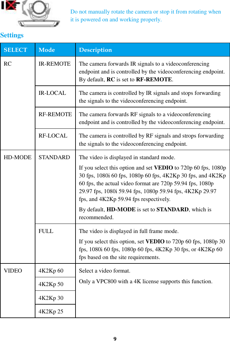
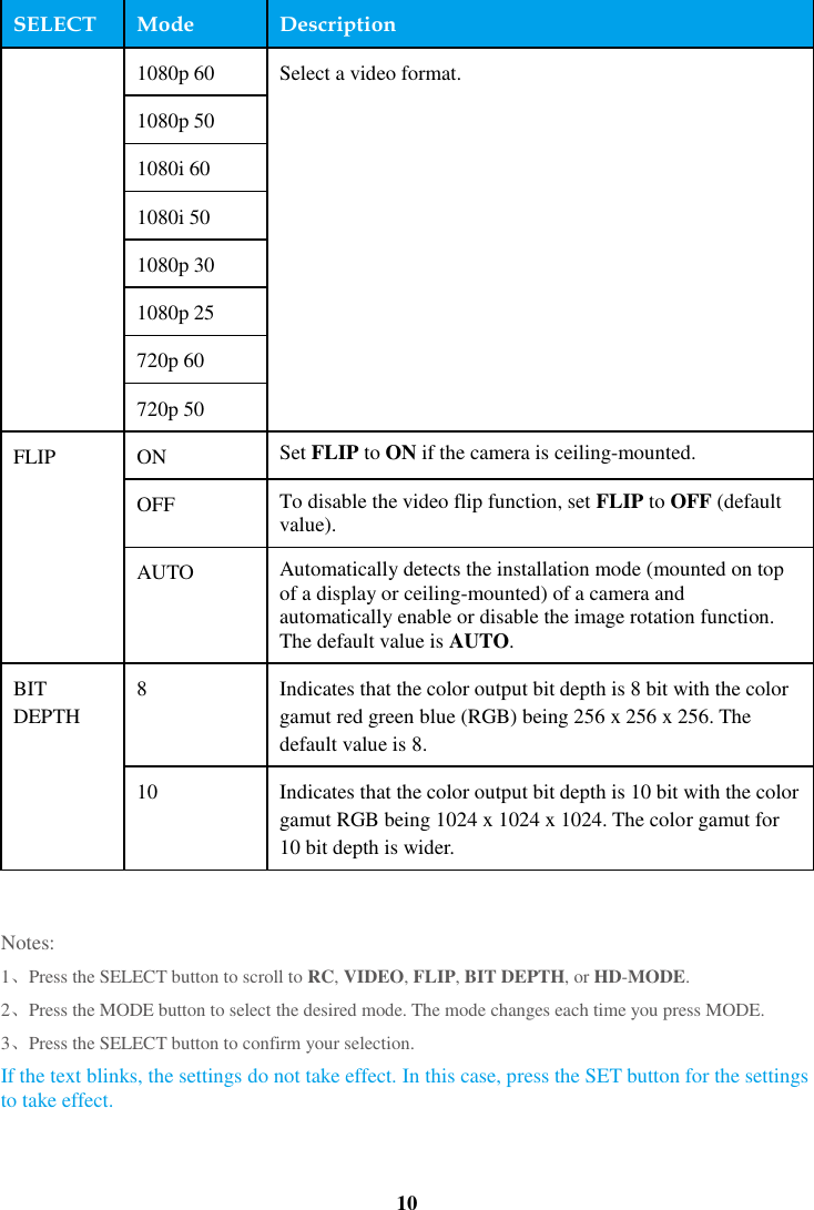
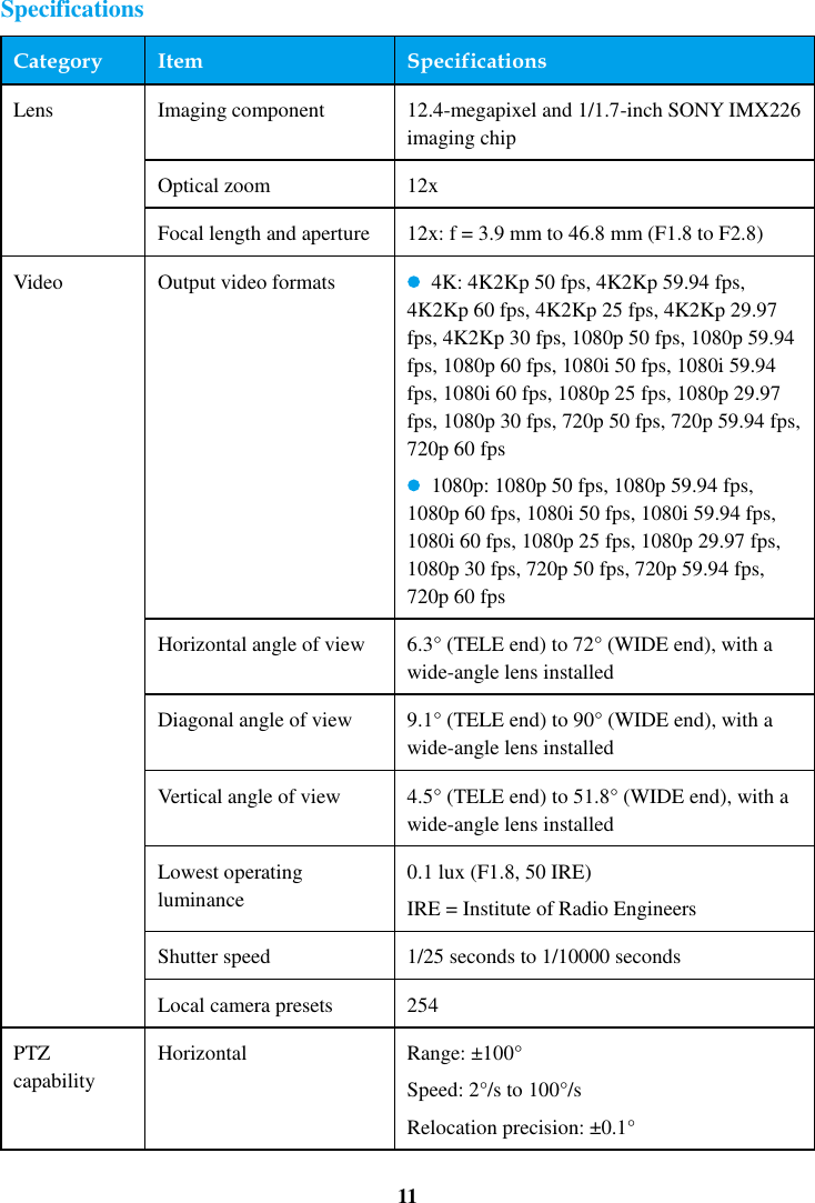
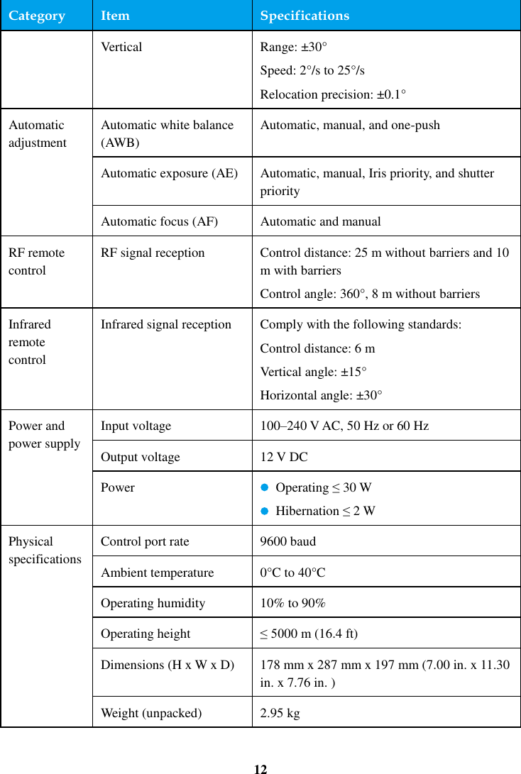
Huawei Technologies VPC800 HD Video Camera User Manual

Huawei Technologies Co.,Ltd HD Video Camera

User Manual

1  Packing List        Power cable (1) Note: Power cables may vary between countries. Camera (1) Power adapter (1)      HDMI cable (1) Note: The HDMI cable is used to connect the camera's HDMI port and a videoconferencing endpoint.    Quick Start Guide (1) Certificate of Compliance & Safety Precautions & Warranty Card (1)  1/4"-20UNC-7 mm Inch screw (1) Used to fix a support.     http://e.huawei.com Issue: 02 (2015-08-08) Copyright © Huawei Technologies Co., Ltd. 2015. All rights reserved.
2  Appearance  No. Port Description 1 Lens 12x optical zoom and 12x digital zoom. 2 RF receiver module Receives radio frequency (RF) signals. 3 MODE button Switches to your desired submenu. 4 Infrared receiver module Receives infrared signals. 5 Display Displays camera model and version information and then license information (1080p or 4K) when a VPC800 is powered on. Displays settings information when a VPC800 is running properly. Displays the error code for a self-check error or PTZ rotation error when an error occurs.   6 Status indicator Indicates running, sleep, faulty, and upgrade states. 7 SELECT button Selects a parameter or its mode. 8 Power button Powers the camera on or off. This button is valid when the camera is connected to a power adapter and is not used with TX or TEX0 series
3  No. Port Description videoconferencing endpoints. 9 Power port Functions as a 12 V DC power input port. 10 SDI port Functions as a bayonet-neill-concelman (BNC) connector to output 3G-SDI and HD-SDI signals. 3G = 3rd Generation HD = high definition SDI = serial digital interface 11 VISCA IN port Functions as a serial port to connect to an HD videoconferencing endpoint or cascades to an upper-level camera. In addition, this port can be used to upgrade the camera. 12 VISCA OUT port Cascades a lower-level camera. This port complies with the Video System Control Architecture (VISCA) standard. VISCA is a trademark of Sony Corporation. 13 HDMI OUT port Outputs HDMI2.0 signals and supports a resolution of up to 4K2Kp 60 fps.   14 HD-VI port Inputs serial control signals, infrared signals, and 12 V power. Outputs digital visual interface (DVI) or YPbPr video signals. 15 Network port Performs operations such as camera upgrade as well as camera angle adjustment (upward, downward, left, or right) and image scaling (zoom in or out) through Telnet.   Installation The VPC800 can be mounted on top of a display(such as TV set and monitor), wall-mounted, ceiling-mounted, or placed horizontally, which you can select based on the site requirements.   If the displayis thicker than 170 mm or the display is wall-mounted, the VPC800 can be installed in any possible way other than be mounted on top of the display.     If the display is 170 mm or thinner, the VPC800 can be mounted on top of a display or placed horizontally. Placed Horizontally Place the camera on a flat surface. If you have to place the camera on a sloping surface, ensure that the slope is less than ±15° or the camera may not function properly. Mounted on Top of a Display Use the L-shaped bracket and its accessories to secure the
4  VPC800 on top of the display. The following figure shows the installation procedure.
5   Wall-Mounted Use the L-shaped bracket and its accessories to mount the VPC800 on the wall. Prepare the hammer drill, rechargeable battery-powered electric screwdriver, hammer, and Phillips screwdriver by yourself. Drill four holes in the wall for mounting the bracket, each with a diameter of 8 mm (0.31 in.) and depth of 35 mm (1.38 in.). The two holes in the upper part must be parallel to the horizontal plane to ensure that the endpoint is horizontally installed. Then follow the steps in the following figure to install the VPC800.
6
7  Ceiling-Mounted Purchase a bracket for inverted installation and mount the VPC800 onto the ceiling using the bracket. The bracket must meet the following requirements:   It is able to bear a weight of at least 10.5 kg (18.74 lb) and has a thickness between 2 mm (0.08 in.) to 3 mm (0.12 in.).   It comes with a location pillar, which can be inserted into the location hole of the VPC800. The distance between the screw hole on the bracket and location pillar must be 14.5 mm (0.57 in.), which is also the distance between the two holes on the bottom of the VPC800.   It comes with a screw hole and one or more 1/4"-20UNC screw.   Note When attaching the purchased bracket and VPC800, it is recommended that you use a 1/4"-20UNC screw delivered with the purchased bracket rather than a 1/4"-20UNC screw delivered with the VPC800 because the length of the latter may be too long or too short to hold up the purchased bracket. Others Install the camera on a tripod (separately purchased). Powering the Camera On   Connect the cables and power adapter to the camera and press the power button. About 18 seconds later, video is displayed on the display device. The camera faces forward the first time you power it on. Afterward, the camera restores to the position before its power-off each time the camera is powered on. If the HD-VI port of the camera is connected to a TEX0 videoconferencing endpoint or a TX series videoconferencing endpoint, you do not need to connect the power adapter to the camera
8  or press the power button. When the videoconferencing endpoint is powered on, it supplies power to the camera to power the camera on. Checking the Status Indicator   Steady green: The camera is working properly.   Steady yellow: The camera is in sleep mode.   Blinking green: The camera is upgrading.   Blinking red: The camera is faulty. Controlling the Camera   The camera supports PTZ and lens control using an HD videoconferencing endpoint or remote control.   To control the camera using an HD videoconferencing endpoint, connect the camera to the videoconferencing endpoint using a serial cable. The maximum control length (cable length) is 50 m.   To control the camera using a remote control, set the infrared (RC) mode to IR-LOCAL or RF-LOCAL.   Use the remote control to hide or display the On-Screen Display (OSD) configuration screen. On the screen, you can perform image-related settings, for example, setting the image output format and enable or disable the image inversion mode. The following table describes the keys on the remote control, which are used to control the OSD configuration screen. Key Description  Press it twice to hide or display the OSD configuration screen. (The OSD configuration screen is displayed topmost.)  Press it to confirm an operation.  On the OSD configuration screen, press them to move to desired options.
9   Settings SELECT Mode Description RC IR-REMOTE The camera forwards IR signals to a videoconferencing endpoint and is controlled by the videoconferencing endpoint. By default, RC is set to RF-REMOTE. IR-LOCAL The camera is controlled by IR signals and stops forwarding the signals to the videoconferencing endpoint. RF-REMOTE The camera forwards RF signals to a videoconferencing endpoint and is controlled by the videoconferencing endpoint.   RF-LOCAL The camera is controlled by RF signals and strops forwarding the signals to the videoconferencing endpoint. HD-MODE STANDARD The video is displayed in standard mode. If you select this option and set VEDIO to 720p 60 fps, 1080p 30 fps, 1080i 60 fps, 1080p 60 fps, 4K2Kp 30 fps, and 4K2Kp 60 fps, the actual video format are 720p 59.94 fps, 1080p 29.97 fps, 1080i 59.94 fps, 1080p 59.94 fps, 4K2Kp 29.97 fps, and 4K2Kp 59.94 fps respectively. By default, HD-MODE is set to STANDARD, which is recommended. FULL The video is displayed in full frame mode. If you select this option, set VEDIO to 720p 60 fps, 1080p 30 fps, 1080i 60 fps, 1080p 60 fps, 4K2Kp 30 fps, or 4K2Kp 60 fps based on the site requirements.   VIDEO 4K2Kp 60 Select a video format. Only a VPC800 with a 4K license supports this function.   4K2Kp 50 4K2Kp 30 4K2Kp 25 Do not manually rotate the camera or stop it from rotating when it is powered on and working properly.
10  SELECT Mode Description 1080p 60 Select a video format. 1080p 50 1080i 60 1080i 50 1080p 30 1080p 25 720p 60 720p 50 FLIP ON Set FLIP to ON if the camera is ceiling-mounted. OFF To disable the video flip function, set FLIP to OFF (default value). AUTO Automatically detects the installation mode (mounted on top of a display or ceiling-mounted) of a camera and automatically enable or disable the image rotation function. The default value is AUTO.   BIT DEPTH 8 Indicates that the color output bit depth is 8 bit with the color gamut red green blue (RGB) being 256 x 256 x 256. The default value is 8. 10 Indicates that the color output bit depth is 10 bit with the color gamut RGB being 1024 x 1024 x 1024. The color gamut for 10 bit depth is wider.    Notes: 1、Press the SELECT button to scroll to RC, VIDEO, FLIP, BIT DEPTH, or HD-MODE. 2、Press the MODE button to select the desired mode. The mode changes each time you press MODE. 3、Press the SELECT button to confirm your selection. If the text blinks, the settings do not take effect. In this case, press the SET button for the settings to take effect.
11  Specifications Category Item Specifications Lens Imaging component 12.4-megapixel and 1/1.7-inch SONY IMX226 imaging chip Optical zoom 12x Focal length and aperture 12x: f = 3.9 mm to 46.8 mm (F1.8 to F2.8) Video Output video formats   4K: 4K2Kp 50 fps, 4K2Kp 59.94 fps, 4K2Kp 60 fps, 4K2Kp 25 fps, 4K2Kp 29.97 fps, 4K2Kp 30 fps, 1080p 50 fps, 1080p 59.94 fps, 1080p 60 fps, 1080i 50 fps, 1080i 59.94 fps, 1080i 60 fps, 1080p 25 fps, 1080p 29.97 fps, 1080p 30 fps, 720p 50 fps, 720p 59.94 fps, 720p 60 fps   1080p: 1080p 50 fps, 1080p 59.94 fps, 1080p 60 fps, 1080i 50 fps, 1080i 59.94 fps, 1080i 60 fps, 1080p 25 fps, 1080p 29.97 fps, 1080p 30 fps, 720p 50 fps, 720p 59.94 fps, 720p 60 fps Horizontal angle of view 6.3° (TELE end) to 72° (WIDE end), with a wide-angle lens installed Diagonal angle of view 9.1° (TELE end) to 90° (WIDE end), with a wide-angle lens installed Vertical angle of view 4.5° (TELE end) to 51.8° (WIDE end), with a wide-angle lens installed Lowest operating luminance 0.1 lux (F1.8, 50 IRE) IRE = Institute of Radio Engineers Shutter speed 1/25 seconds to 1/10000 seconds Local camera presets 254 PTZ capability Horizontal Range: ±100° Speed: 2°/s to 100°/s Relocation precision: ±0.1°
12  Category Item Specifications Vertical Range: ±30° Speed: 2°/s to 25°/s Relocation precision: ±0.1° Automatic adjustment Automatic white balance (AWB) Automatic, manual, and one-push Automatic exposure (AE) Automatic, manual, Iris priority, and shutter priority Automatic focus (AF) Automatic and manual RF remote control RF signal reception Control distance: 25 m without barriers and 10 m with barriers Control angle: 360°, 8 m without barriers Infrared remote control Infrared signal reception Comply with the following standards: Control distance: 6 m Vertical angle: ±15° Horizontal angle: ±30° Power and power supply Input voltage 100–240 V AC, 50 Hz or 60 Hz Output voltage 12 V DC Power   Operating ≤ 30 W   Hibernation ≤ 2 W Physical specifications Control port rate 9600 baud Ambient temperature 0°C to 40°C Operating humidity 10% to 90% Operating height ≤ 5000 m (16.4 ft) Dimensions (H x W x D) 178 mm x 287 mm x 197 mm (7.00 in. x 11.30 in. x 7.76 in. ) Weight (unpacked) 2.95 kg
13  Safety Precautions   Before you use the product, refer to the product vendor for version mapping information and to confirm compatibility with other videoconferencing equipment.   Keep the device dry and prevent it from colliding with other objects during storage, transportation, and operations.     During installation and commissioning, ensure that the camera is properly grounded, and do not insert or remove the camera video cables when the camera is powered on.   Do not use any power adapter other than the one provided with the device. In addition, do not refit the adapter.   Do not attempt to dismantle the device. In case of any faults, contact an authorized maintenance center.   Position the device on stable surfaces only.   Keep the device or its accessories away from children. Swallowing the accessories may be fatal.   Keep the power plug clean and dry to prevent electric shocks or other hazards.   Before cleaning the device, shut it down and disconnect the power supply.   Do not press, scratch, or hit the lens and display with force.   Do not touch the lens or display with any rubber or plastic items as doing so may impair brightness.   Dispose packaging, batteries, and the devices according to the local regulations. Please recycle if possible. To know more precautions, contact your device provider.   This is a class A product. In a living environment, this product may cause radio interference in which case the user may be required to take preventative measures.
14  Troubleshooting Question Why can't I use PTZ to control the camera from an HD videoconferencing endpoint? Answer The serial connection between the camera and the HD videoconferencing endpoint is incorrect. The serial port of the HD videoconferencing endpoint type is set incorrectly. Question Why does the camera fail its startup diagnosis along with one of the following symptoms: 1) The camera fails to start. 2) The PTZ generates abnormal noise. 3) Nothing is displayed on the camera screen? Answer A nonstandard power adapter may be used. The standard one provides a 12 V DC output.   The connector at the low-voltage side of the camera's power adapter has been reconstructed, or the cable of this power connector has been extended. If the cable of the camera adapter is not long enough, extend the cable of the power socket. Question Why is the camera video not displayed on the display connected to the HD videoconferencing endpoint? Answer The HD videoconferencing endpoint and camera are not connected correctly. The input and output settings on the HD videoconferencing endpoint are incorrect. The HD videoconferencing endpoint does not support the camera's video format. The display does not support the video output format set on the HD videoconferencing endpoint. Question Why does the display fail to display any video after the camera has worked for a period? Answer Check the camera's working environment. For example, check whether the cables are connected securely, whether the voltage is stable, and whether heat is dissipated properly. Question Why is the camera video displayed unclearly or why cannot the camera automatically adjust its focus after the camera is powered on? Answer The lens surface is not clean, with dust, fingerprint, or mist on it. The camera is not in autofocus mode.
15  To set the camera to autofocus mode, perform the following operations:   Press    on the remote control to access the camera control page. On the remote control interface, select Adjust Focus, use the direction keys to select   on the remote control to set the camera to autofocus mode. The distance between the object and the camera is less than 0.7 meters, or the camera shooting angle is improperly set.   Question Do the cameras support daisy chain cascade control? If daisy chain cascade control is supported, how are the cameras connected and controlled? How are the camera address codes set? Why cannot the cameras be controlled after they are connected? Answer The Huawei VPC800 camera supports the Video System Control Architecture (VISCA) protocol and cascade control. Connection method: Use a keyboard that supports the VISCA protocol to connect the cameras. Connect the VISCA IN port of the first camera to the VISCA keyboard. Then, connect the VISCA OUT port of the first camera to the VISCA IN port of the second camera, the VISCA OUT port of the second camera to the VISCA IN port of the third camera, and so on. A maximum of seven cameras can be connected in this serial connection mode. The VISCA protocol supports cascade control of a maximum of seven cameras. The address codes are automatically negotiated and increase by 1 from the first camera to the seventh camera. If the control is abnormal, check the cables and their connections. Ensure that the cables and their connections are normal. Ensure that the keyboard can properly control the first camera. If the first camera can be properly controlled but the other ones cannot, check the cable length. Ensure that the cable length does not exceed 50 meters. If the fault persists, restart the keyboard and the cameras.
16  Dimensions
17  Pin Assignment  No. Pins(VISCA IN) Pins(VISCA OUT) 1 DTR NC 2 NC DSR 3 TXD TXD 4 GND GND 5 RXD RXD 6 GND GND 7 IR OUT NC 8 NC NC
          Regulatory Compliance Statement                    -HUAWEI VPC800   Issue : 01  Date: 2015-6-14  HUAWEI TECHNOLOGIES CO., LTD.
 Issue    (01) Huawei Proprietary and Confidential                                     Copyright © Huawei Technologies Co., Ltd. i    Copyright © Huawei Technologies Co., Ltd. 2010. All rights reserved. No  part  of  this  document  may  be  reproduced  or  transmitted  in  any  form  or  by  any  means  without  prior  written consent of Huawei Technologies Co., Ltd.  Trademarks and Permissions   and other Huawei trademarks are trademarks of Huawei Technologies Co., Ltd. All other trademarks and trade names mentioned in this document are the property of their respective holders.  Notice The purchased products, services and features are stipulated by the contract made between Huawei and the customer. All or part of the products, services and features described in this document may not be within the purchase scope or the usage scope. Unless otherwise specified in the contract, all statements, information, and recommendations in this document  are  provided  "AS  IS"  without  warranties,  guarantees  or  representations  of  any  kind,  either  express  or implied. The information in this document is subject to change without notice. Every effort has been made in the preparation of this document to ensure accuracy of the contents, but  all statements, information, and recommendations in this document do not constitute the warranty of any kind, express or implied.     Huawei Technologies Co., Ltd. Address: Huawei Industrial Base Bantian, Longgang Shenzhen 518129 People's Republic of China Website: http://www.huawei.com Email: support@huawei.com
  1 Regulatory Compliance Statement  Issue    (01) Huawei Proprietary and Confidential                                     Copyright © Huawei Technologies Co., Ltd. 1-1  1 Regulatory Compliance Statement About This Chapter 1.1    Declaration of Conformity to European Directives
1 Regulatory Compliance Statement    1-2 Huawei Proprietary and Confidential                                     Copyright © Huawei Technologies Co., Ltd. Issue    ()  1.1 Declaration of Conformity to European Directives Figure 1-1 Declaration of Conformity to European Directives
  2 Regulatory Compliance Information  Issue    (01) Huawei Proprietary and Confidential                                     Copyright © Huawei Technologies Co., Ltd. 2-3  2 Regulatory Compliance Information About This Chapter 2.1 Regulatory Compliance Standards 2.2 European Regulatory Compliance 2.3 U.S.A Regulatory Compliance 2.4 China RoHS hazardous substance table 2.5 Other Markets 2.1 Regulatory Compliance Standards This product complies with the standards listed in Table 2-1. Table 2-1 Regulatory compliance standards Discipline Standards EMC  CISPR22 Class A  CISPR24  EN55022 Class A  EN50024  ETSI EN 301 489 Class A  CFR 47 FCC Part 15 Class A  ICES 003 Class A  AS/NZS CISPR22 Class A  CNS 13438 Class A  IEC61000-3-2  IEC61000-3-3  EN61000-6-2  EN61000-6-4
2 Regulatory Compliance Information    2-4 Huawei Proprietary and Confidential                                     Copyright © Huawei Technologies Co., Ltd. Issue    ()  Discipline Standards Safety  IEC 60950-1  EN 60950-1  UL 60950-1  CSA C22.2 No 60950-1  AS/NZS 60950.1  BS EN 60950-1 RF  ETSI EN 301 489-1  ETSI EN 301 489 -17  EN300 440 -1  EN300 440 -2  EN62479:2010  FCC Part 15  AS/NZS 4268 Health  ICNIRP Guideline  1999-519-EC  EN 50385  EN 62311  EN62479  OET Bulletin 65  IEEE Std C95.1 Environmental protection  2011/65/EU (RoHS)  EC NO. 1907/2006 (REACH)  2002/96/EC (WEEE) NOTE EMC: electromagnetic compatibility RF: radio frequency EN: European Standard ETSI: European Telecommunications Standards Institute CFR: Code of Federal Regulations FCC: Federal Communication Commission IEC: International Electrotechnical Commission AS/NZS: Australian/New Zealand Standard VCCI: Voluntary Control Council for Interference UL: Underwriters Laboratories GR: General Requirement FDA: Food and Drug Administration ICNIRP: International Commission on Non-Ionizing Radiation Protection OET: Office of Engineering Technology IEEE: Institute of Electrical and Electronics Engineers RoHS: restriction of the use of certain hazardous substances
  2 Regulatory Compliance Information  Issue    (01) Huawei Proprietary and Confidential                                     Copyright © Huawei Technologies Co., Ltd. 2-5   2.2   European Regulatory Compliance This product complies with the following European directives and regulations.  2004/108/EC (EMC)  2006/95/EC (low voltage)  1999/5/EC (R&TTE)  2011/65/EU (RoHS)  EC NO. 1907/2006 (REACH)  2002/96/EC (WEEE) Product complies with Directive 2002/95/EC, 2011/65/EU and other similar regulations from the countries outside the European Union, on the RoHS in electrical and electronic equipment. The  device  does  not  contain  lead,  mercury,  cadmium,  and  hexavalent  chromium  and brominated flame retardants (Polybrominated Biphenyls (PBB) or Polybrominated Diphenyl Ethers  (PBDE))  except  for  those  exempted  applications  allowed  by  RoHS  directive  for technical reasons.   Product complies with Regulation EC NO. 1907/2006 (REACH) and other similar regulations from the countries outside the European Union. Huawei will notify to the European Chemical Agency (ECHA) or the customer when necessary and regulation requires.  Product  complies  with  Directive  2002/96/EC  on  waste electrical and  electronic  equipment (WEEE).  Huawei  is  responsible  for  recycling  its  end-of-life  devices,  and  please  contact Huawei local service center when recycling is required. Huawei strictly complies with the EU Waste Electrical and Electronic Equipment Directive (WEEE Directive) and electronic waste management regulations enacted by different countries worldwide. In addition, Huawei has established a system for recycling and reuse of electronic wastes, and it can provide service of dismantling and recycling for WEEE. By Huawei recycling system, the waste can be handled environmentally  and  the  resource  can  be  recycled and  reused  fully,  which  is  also  Huawei WEEE  stratagem  in  the  word.  Most  of  the  materials  in  product  are  recyclable,  and  our packaging is designed to be recycled and should be handled in accordance with your local recycling policies.   In accordance  with Article 11(2) in Directive 2002/96/EC (WEEE), products  were marked with the following symbol: a cross-out wheeled waste bin with a bar beneath as below:
2 Regulatory Compliance Information    2-6 Huawei Proprietary and Confidential                                     Copyright © Huawei Technologies Co., Ltd. Issue    ()  2.3 U.S.A Regulatory Compliance 2.3.1    FCC Part 15   2.3.1 FCC Part 15 HUAWEI VPC800 complies with Part 15 of the FCC Rules. Operation is subject to the following two conditions:  This device does not cause harmful interference.  This device must accept any interference received, including interference that may cause undesired operation. If this device is modified without authorization from Huawei, the device may no longer comply with FCC requirements for Class A digital devices. In that a case, your right to use the device may be limited by FCC regulations. Moreover, you may be required to correct any interference to radio or television communications at your own expense. This device has been tested and found to comply with the limits for a Class A digital device, pursuant to Part 15 of the FCC Rules. These limits are designed to provide reasonable protection against harmful interference when the device is operated in a commercial environment. This device generates, uses and radiates radio frequency energy. If it is not installed and used in accordance with the instructions, it may cause harmful interference to radio communications. Operation of this device in a residential area is likely to cause harmful interference. In this case the user will be requested to correct the interference at his or her own expense. In order to avoid the possibility of exceeding the FCC radio frequency exposure limits, human proximity to the equipment shall not be less than 0.2 m  2.4 China RoHS hazardous substance table  This products described in this guide complies with “the Administration on the Control of Pollution Caused by Electronic Information Products” which is also called China RoHS Part Descriptions Restricted Substances in Product Cd Pb Hg Cr(VI) PBBs PBDEs Alloy Parts ○ X ○ ○ ○ ○ Metal Fitting ○ ○ ○ ○ ○ ○ PCBA ○ X ○ ○ ○ ○
  2 Regulatory Compliance Information  Issue    (01) Huawei Proprietary and Confidential                                     Copyright © Huawei Technologies Co., Ltd. 2-7  Other electronics ○ X ○ ○ ○ ○ Solder ○ ○ ○ ○ ○ ○ Plastic and Polymer ○ ○ ○ ○ ○ ○  〇:表示该有毒有害物质在该部件所有均质材料中的含量均在SJ/T11363-2006 标准规定的限量要求以下。 ╳:表示该有毒有害物质至少在该部件的某一均质材料中的含量超出SJ/T11363-2006 标准规定的限量要求。 2.5 Other Markets For relevant compliance information/documentation for markets not mentioned above, Please contact Huawei representative

Navigation menu