Huawei ME909s Series LTE Module Application Guide (V100R001 04, English)
2018-05-24
User Manual: Huawei
Open the PDF directly: View PDF ![]() .
.
Page Count: 201 [warning: Documents this large are best viewed by clicking the View PDF Link!]
- About This Document
- Contents
- 1 Overview
- 2 Initialization Application Scenarios
- 3 Serial Port Configuration Application Scenarios
- 4 External Protocol Stack Application Scenarios
- 5 Internal Protocol Stack Application Scenarios-TCP/UDP
- 6 Internal Protocol Stack Application Scenarios-FTP
- 6.1 Creating an FTP Control Link
- 6.2 Configuring Data Transmission Mode
- 6.3 Configuring FTP Data Channel Mode
- 6.4 Getting FTP File Size
- 6.5 Downloading File Using "GET" Command in Transparent Mode
- 6.6 Downloading File Using "GET" Command in Command Mode
- 6.7 Download File Using "GET" Command in Buffer Mode
- 6.8 Uploading File Using "PUT" Command in Transparent Mode
- 6.9 Uploading File Using "PUT" Command in Command Mode and Buffer Mode
- 6.10 FTP Error Codes
- 7 Internal Protocol Stack Application Scenarios-HTTP
- 7.1 Creating an HTTP Server Link
- 7.2 Configuring Data Transmission Mode
- 7.3 Downloading File Using "GET" Command in Transparent Mode
- 7.4 Downloading File Using "GET" Command in Command Mode
- 7.5 Downloading File Using "GET" Command in Buffer Mode
- 7.6 Uploading File Using "POST" Command in Transparent Mode
- 7.7 Uploading File"POST" Command in Command Mode and Buffer Mode
- 7.8 HTTP Error Codes
- 8 Internal Protocol Stack Application Scenarios-SMTP
- 9 Internal Protocol Stack Application Scenarios-FTPS/HTTPS/SMTPS
- 10 SSL Application Scenarios
- 11 ECM Application Scenarios
- 12 Voice and Supplementary Service Application Scenarios
- 13 Text Message Application Scenarios
- 14 Phonebook Application Scenarios
- 15 SIM Operation Application Scenarios
- 16 Sleeping and Waking Up Application Scenarios
- 16.1 Overview
- 16.2 Hardware Interfaces
- 16.3 Sequence Diagram
- 16.4 Software Interfaces
- 16.5 Application Scenarios: System with USB Connection only
- 16.6 Application Scenarios: System with USB and WAKEUP_OUT
- 16.7 Application Scenarios: System with UART and WAKEUP_OUT/WAKEUP_IN
- 16.8 System with Other Connection Methods
- 16.9 Solution to Time-expired USB Reset to Suspended Device
- 17 Thermal Protection Application Scenarios
- 18 Concurrent Service Application Scenarios
- 19 STK Application Scenarios
- 20 TTS Application Scenarios
- 21 FOTA Application Scenarios
- 21.1 Overview
- 21.2 FOTA Process
- 21.3 Setting FOTA Mode
- 21.4 Setting FOTA Connection Parameters
- 21.5 Manually Querying for Upgrade Firmware Version
- 21.6 Periodically Querying the Version
- 21.7 Manually Downloading the Version
- 21.8 Automatically Downloading the Firmware
- 21.9 Using the Resumable Data Transfer Function
- 21.10 Manually Canceling the Download
- 21.11 Manually Upgrading the Version
- 21.12 Automatically Upgrading the Version
- 21.13 Enable or Disable FOTA SMS Auto-Download
- 21.14 FOTA Notification Reception Application Scenarios
- 21.15 FOTA Process Startup Application Scenarios
- 22 LED Indication Application Scenarios
- 23 Local Upgrade Application Scenarios
- 24 eCall Application Scenarios
- 24.1 Performance Specifications for MSD Transmission
- 24.2 AT Command Initiating Port
- 24.3 Precautions for Using ECLPUSH
- 24.4 Method for Improving the eCall Setup Success Rate
- 24.5 Handling Conflicts Between eCall and Other Voice Calls
- 24.6 Manual Initiation of eCall Emergency Calls
- 24.7 Automatic Initiation of eCall Emergency Calls by the Vehicle
- 24.8 Manual Initiation of eCall Test Calls
- 24.9 Automatic Initiation of eCall Test Calls by the Vehicle
- 24.10 MSD Update Request to the User
- 24.11 Unsolicited MSD Transmission by the IVS
- 24.12 Unsolicited Report of eCall Redial Information
- 24.13 Hanging Up eCall Voice Calls
- 25 Netscan Application Scenarios
- 26 Network Monitoring Application Scenarios
- 27 Cell Lock Application Scenarios
- 28 FREQLOCK Application Scenarios
- 29 MultiPDP Application Scenarios
- 30 Recorder Application Scenarios
- 31 Appendix

HUAWEI ME909s Series LTE Module
V100R001
Application Guide
Issue
04
Date
2017-12-11

Copyright © Huawei Technologies Co., Ltd. 2017. All rights reserved.
No part of this manual may be reproduced or transmitted in any form or by any means without prior written
consent of Huawei Technologies Co., Ltd. and its affiliates ("Huawei").
The product described in this manual may include copyrighted software of Huawei and possible licensors.
Customers shall not in any manner reproduce, distribute, modify, decompile, disassemble, decrypt, extract,
reverse engineer, lease, assign, or sublicense the said software, unless such restrictions are prohibited by
applicable laws or such actions are approved by respective copyright holders.
Trademarks and Permissions
, , and are trademarks or registered trademarks of Huawei Technologies Co., Ltd.
LTE is a trade mark of ETSI.
Other trademarks, product, service and company names mentioned may be the property of their respective
owners.
Notice
Some features of the product and its accessories described herein rely on the software installed, capacities
and settings of local network, and therefore may not be activated or may be limited by local network operators
or network service providers.
Thus, the descriptions herein may not exactly match the product or its accessories which you purchase.
Huawei reserves the right to change or modify any information or specifications contained in this manual
without prior notice and without any liability.
DISCLAIMER
ALL CONTENTS OF THIS MANUAL ARE PROVIDED “AS IS”. EXCEPT AS REQUIRED BY APPLICABLE
LAWS, NO WARRANTIES OF ANY KIND, EITHER EXPRESS OR IMPLIED, INCLUDING BUT NOT
LIMITED TO, THE IMPLIED WARRANTIES OF MERCHANTABILITY AND FITNESS FOR A PARTICULAR
PURPOSE, ARE MADE IN RELATION TO THE ACCURACY, RELIABILITY OR CONTENTS OF THIS
MANUAL.
TO THE MAXIMUM EXTENT PERMITTED BY APPLICABLE LAW, IN NO EVENT SHALL HUAWEI BE
LIABLE FOR ANY SPECIAL, INCIDENTAL, INDIRECT, OR CONSEQUENTIAL DAMAGES, OR LOSS OF
PROFITS, BUSINESS, REVENUE, DATA, GOODWILL SAVINGS OR ANTICIPATED SAVINGS
REGARDLESS OF WHETHER SUCH LOSSES ARE FORSEEABLE OR NOT.
THE MAXIMUM LIABILITY (THIS LIMITATION SHALL NOT APPLY TO LIABILITY FOR PERSONAL
INJURY TO THE EXTENT APPLICABLE LAW PROHIBITS SUCH A LIMITATION) OF HUAWEI ARISING
FROM THE USE OF THE PRODUCT DESCRIBED IN THIS MANUAL SHALL BE LIMITED TO THE
AMOUNT PAID BY CUSTOMERS FOR THE PURCHASE OF THIS PRODUCT.
Import and Export Regulations
Customers shall comply with all applicable export or import laws and regulations and be responsible to obtain
all necessary governmental permits and licenses in order to export, re-export or import the product mentioned
in this manual including the software and technical data therein.

HUAWEI ME909s Series LTE Module
Application Guide
About This Document
Issue 04 (2017-12-11)
Huawei Proprietary and Confidential
Copyright © Huawei Technologies Co., Ltd.
3
About This Document
Revision History
Document
Version
Date
Chapter
Description
01
2015-07-30
Creation
02
2015-11-30
5
Updated the chapter Internal Protocol Stack
Application Scenarios-TCP/UDP.
6
Updated the chapter Internal Protocol Stack
Application Scenarios-FTP.
7
Updated the chapter Internal Protocol Stack
Application Scenarios-HTTP.
8
Updated the chapter Internal Protocol Stack
Application Scenarios-SMTP.
9
Updated the chapter Internal Protocol Stack
Application Scenarios-FTPS/HTTPS/SMTPS.
03
2016-11-25
10.2.1
Added the NOTE for SSL cipher suites
11.2.1
Updated the Reference Process
11.3.1
Updated the Reference Process
23.1.1
Updated the Differential upgrade flow and
Full upgrade flow
04
2017-12-11
Deleted privacy policy
Scope
ME909s-821
ME909s-821 Mini PCIe
ME909s-120
ME909s-120 Mini PCIe

HUAWEI ME909s Series LTE Module
Application Guide
Contents
Issue 04 (2017-12-11)
Huawei Proprietary and Confidential
Copyright © Huawei Technologies Co., Ltd.
4
Contents
1 Overview ....................................................................................................................................... 15
1.1 Conventions and Definitions .......................................................................................................................... 15
1.1.1 Conventions .......................................................................................................................................... 15
1.1.2 Definitions ............................................................................................................................................ 16
1.2 Basic AT Command Processing Principles ..................................................................................................... 16
1.2.1 Ports ...................................................................................................................................................... 16
1.2.2 AT Command Processing Mechanism ................................................................................................... 17
1.2.3 Recommended Timeout Mechanism for AT Commands Processed by a Host...................................... 19
2 Initialization Application Scenarios ....................................................................................... 21
2.1 Startup Indication ^SYSSTART ..................................................................................................................... 21
2.1.1 Reference Process ................................................................................................................................. 21
2.1.2 Troubleshooting .................................................................................................................................... 21
2.2 Querying Basic Information ........................................................................................................................... 22
2.2.1 Reference Process ................................................................................................................................. 22
2.2.2 Troubleshooting .................................................................................................................................... 22
2.3 Network Service Operations .......................................................................................................................... 22
2.3.1 Reference Process ................................................................................................................................. 22
2.3.2 Troubleshooting .................................................................................................................................... 23
3 Serial Port Configuration Application Scenarios ................................................................. 25
3.1 Overview ........................................................................................................................................................ 25
3.2 Baud Rate Configuration ................................................................................................................................ 25
3.2.1 Reference Process ................................................................................................................................. 25
3.2.2 Troubleshooting .................................................................................................................................... 26
3.3 Baud Rate Autonegotiation ............................................................................................................................ 26
3.3.1 Reference Process ................................................................................................................................. 26
3.3.2 Troubleshooting .................................................................................................................................... 27
3.4 DTR Hang Up Data Services ......................................................................................................................... 27
3.4.1 Reference Process ................................................................................................................................. 27
3.4.2 Troubleshooting .................................................................................................................................... 27
3.5 DCD Pin Control ............................................................................................................................................ 28
3.5.1 Reference Process ................................................................................................................................. 28
3.5.2 Troubleshooting .................................................................................................................................... 28

HUAWEI ME909s Series LTE Module
Application Guide
Contents
Issue 04 (2017-12-11)
Huawei Proprietary and Confidential
Copyright © Huawei Technologies Co., Ltd.
5
3.6 Setting Hardware Flow Control ..................................................................................................................... 28
3.6.1 Reference Process ................................................................................................................................. 28
3.6.2 Troubleshooting .................................................................................................................................... 29
4 External Protocol Stack Application Scenarios ..................................................................... 30
4.1 Prerequisites ................................................................................................................................................... 30
4.1.1 Reference Process ................................................................................................................................. 30
4.1.2 Troubleshooting .................................................................................................................................... 31
4.2 Establishing Data Connections ....................................................................................................................... 31
4.2.1 Reference Process ................................................................................................................................. 31
4.2.2 Troubleshooting .................................................................................................................................... 32
4.3 Data Transmission .......................................................................................................................................... 32
4.4 Switch Between Data Mode and Command Mode ........................................................................................ 34
4.4.1 Reference Process ................................................................................................................................. 34
4.4.2 Troubleshooting .................................................................................................................................... 34
4.5 Disconnecting Data Service Connections ...................................................................................................... 35
4.5.1 Reference Process ................................................................................................................................. 35
5 Internal Protocol Stack Application Scenarios-TCP/UDP .................................................. 36
5.1 Overview ........................................................................................................................................................ 36
5.2 Initializing Internet Services .......................................................................................................................... 36
5.2.1 Reference Process ................................................................................................................................. 36
5.2.2 Troubleshooting .................................................................................................................................... 37
5.3 Creating a Listen Server ................................................................................................................................. 37
5.3.1 Reference Process ................................................................................................................................. 37
5.3.2 Troubleshooting .................................................................................................................................... 38
5.4 Creating TCP/UDP Links ............................................................................................................................... 38
5.4.1 Reference Process ................................................................................................................................. 38
5.4.2 Troubleshooting .................................................................................................................................... 39
5.5 Sending Data .................................................................................................................................................. 39
5.5.1 Reference Process ................................................................................................................................. 39
5.5.2 Troubleshooting .................................................................................................................................... 41
5.6 Closing TCP/UDP Links ................................................................................................................................ 41
5.6.1 Reference Process ................................................................................................................................. 41
5.6.2 Troubleshooting .................................................................................................................................... 42
5.7 Transparent Transmission Mode .................................................................................................................... 42
5.7.1 Reference Process ................................................................................................................................. 42
5.7.2 Troubleshooting .................................................................................................................................... 44
5.8 Packet Statistics .............................................................................................................................................. 45
5.8.1 Reference Process ................................................................................................................................. 45
5.9 TCP/UDP Link Change Indication ................................................................................................................. 45
5.9.1 Reference Process ................................................................................................................................. 45
6 Internal Protocol Stack Application Scenarios-FTP ............................................................. 47

HUAWEI ME909s Series LTE Module
Application Guide
Contents
Issue 04 (2017-12-11)
Huawei Proprietary and Confidential
Copyright © Huawei Technologies Co., Ltd.
6
6.1 Creating an FTP Control Link ........................................................................................................................ 47
6.1.1 Reference Process ................................................................................................................................. 47
6.1.2 Troubleshooting .................................................................................................................................... 47
6.2 Configuring Data Transmission Mode ........................................................................................................... 48
6.2.1 Reference Process ................................................................................................................................. 48
6.3 Configuring FTP Data Channel Mode............................................................................................................ 49
6.3.1 Reference Process ................................................................................................................................. 49
6.4 Getting FTP File Size ..................................................................................................................................... 49
6.4.1 Reference Process ................................................................................................................................. 49
6.4.2 Troubleshooting .................................................................................................................................... 50
6.5 Downloading File Using "GET" Command in Transparent Mode ................................................................. 50
6.5.1 Reference Process ................................................................................................................................. 50
6.5.2 Troubleshooting .................................................................................................................................... 51
6.6 Downloading File Using "GET" Command in Command Mode ................................................................... 51
6.6.1 Reference Process ................................................................................................................................. 51
6.7 Download File Using "GET" Command in Buffer Mode .............................................................................. 52
6.7.1 Reference Process ................................................................................................................................. 52
6.8 Uploading File Using "PUT" Command in Transparent Mode ...................................................................... 53
6.8.1 Reference Process ................................................................................................................................. 53
6.9 Uploading File Using "PUT" Command in Command Mode and Buffer Mode ............................................ 54
6.9.1 Reference Process ................................................................................................................................. 54
6.10 FTP Error Codes ........................................................................................................................................... 55
7 Internal Protocol Stack Application Scenarios-HTTP ......................................................... 57
7.1 Creating an HTTP Server Link ....................................................................................................................... 57
7.1.1 Reference Process ................................................................................................................................. 57
7.1.2 Troubleshooting .................................................................................................................................... 57
7.2 Configuring Data Transmission Mode ........................................................................................................... 58
7.2.1 Reference Process ................................................................................................................................. 58
7.3 Downloading File Using "GET" Command in Transparent Mode ................................................................. 58
7.3.1 Reference Process ................................................................................................................................. 58
7.3.2 Troubleshooting .................................................................................................................................... 59
7.4 Downloading File Using "GET" Command in Command Mode ................................................................... 59
7.4.1 Reference Process ................................................................................................................................. 59
7.5 Downloading File Using "GET" Command in Buffer Mode ......................................................................... 60
7.5.1 Reference Process ................................................................................................................................. 60
7.6 Uploading File Using "POST" Command in Transparent Mode .................................................................... 61
7.6.1 Reference Process ................................................................................................................................. 61
7.7 Uploading File"POST" Command in Command Mode and Buffer Mode ..................................................... 61
7.7.1 Reference Process ................................................................................................................................. 61
7.7.2 Troubleshooting .................................................................................................................................... 63
7.8 HTTP Error Codes.......................................................................................................................................... 64

HUAWEI ME909s Series LTE Module
Application Guide
Contents
Issue 04 (2017-12-11)
Huawei Proprietary and Confidential
Copyright © Huawei Technologies Co., Ltd.
7
8 Internal Protocol Stack Application Scenarios-SMTP ......................................................... 65
8.1 Creating an SMTP Server Link ...................................................................................................................... 65
8.1.1 Reference Process ................................................................................................................................. 65
8.1.2 Troubleshooting .................................................................................................................................... 65
8.2 Sending Mail Through "emsend" Without Attachment .................................................................................. 66
8.2.1 Reference Process ................................................................................................................................. 66
8.3 Sending Mail Through "emsend" with Attachment Using 7 bit ..................................................................... 66
8.3.1 Reference Process ................................................................................................................................. 66
8.4 Sending Mail Through "emsend" with Attachment Using base 64 ................................................................ 68
8.4.1 Reference Process ................................................................................................................................. 68
8.4.2 Troubleshooting .................................................................................................................................... 69
8.5 SMTP Error Codes ......................................................................................................................................... 69
9 Internal Protocol Stack Application Scenarios-FTPS/HTTPS/SMTPS............................. 71
9.1 Creating a Secure Control Link ...................................................................................................................... 71
9.1.1 Preliminary Operations ......................................................................................................................... 71
9.1.2 IP Configuration .................................................................................................................................... 71
9.1.3 SSL and TLS ......................................................................................................................................... 72
9.1.4 Certificates ............................................................................................................................................ 72
9.2 Configuring SSL ............................................................................................................................................ 72
9.2.1 Reference Process ................................................................................................................................. 72
10 SSL Application Scenarios ...................................................................................................... 74
10.1 Initializing Secure Services .......................................................................................................................... 74
10.1.1 Reference Process ............................................................................................................................... 74
10.1.2 Troubleshooting .................................................................................................................................. 75
10.2 Configuring SSL .......................................................................................................................................... 75
10.2.1 Reference Process ............................................................................................................................... 75
10.2.2 Troubleshooting .................................................................................................................................. 76
10.3 Managing Certificate/Key ............................................................................................................................ 76
10.3.1 Reference Process ............................................................................................................................... 76
10.3.2 Troubleshooting .................................................................................................................................. 77
10.4 Creating SSL Links ...................................................................................................................................... 78
10.4.1 Reference Process ............................................................................................................................... 78
10.4.2 Troubleshooting .................................................................................................................................. 78
10.5 Querying SSL Status .................................................................................................................................... 79
10.5.1 Reference Process ............................................................................................................................... 79
10.5.2 Troubleshooting .................................................................................................................................. 79
10.6 Sending Data ................................................................................................................................................ 79
10.6.1 Reference Process ............................................................................................................................... 79
10.6.2 Troubleshooting .................................................................................................................................. 80
10.7 Receiving Data ............................................................................................................................................. 81
10.7.1 Reference Process ............................................................................................................................... 81

HUAWEI ME909s Series LTE Module
Application Guide
Contents
Issue 04 (2017-12-11)
Huawei Proprietary and Confidential
Copyright © Huawei Technologies Co., Ltd.
8
10.7.2 Troubleshooting .................................................................................................................................. 81
10.8 Closing SSL ................................................................................................................................................. 82
10.8.1 Reference Process ............................................................................................................................... 82
10.8.2 Troubleshooting .................................................................................................................................. 82
11 ECM Application Scenarios .................................................................................................... 83
11.1 Dialing ECM ................................................................................................................................................ 83
11.1.1 Reference Process ............................................................................................................................... 83
11.1.2 Troubleshooting .................................................................................................................................. 84
11.2 Querying the Dial-up Connection State ........................................................................................................ 85
11.2.1 Reference Process ............................................................................................................................... 85
11.2.2 Troubleshooting .................................................................................................................................. 85
11.3 Disconnecting the Dial-up Connection ......................................................................................................... 85
11.3.1 Reference Process ............................................................................................................................... 85
11.3.2 Troubleshooting .................................................................................................................................. 86
12 Voice and Supplementary Service Application Scenarios ............................................... 87
12.1 Pre-configuration .......................................................................................................................................... 87
12.1.1 Reference Process ............................................................................................................................... 87
12.2 Voice Call Handling ..................................................................................................................................... 87
12.2.1 Reference Process ............................................................................................................................... 87
12.2.2 Troubleshooting .................................................................................................................................. 88
12.3 DTMF Application ....................................................................................................................................... 89
12.3.1 Reference Process ............................................................................................................................... 89
12.3.2 Troubleshooting .................................................................................................................................. 89
12.4 ID Presentation ............................................................................................................................................. 90
12.4.1 Reference Process ............................................................................................................................... 90
12.4.2 Troubleshooting .................................................................................................................................. 92
12.5 Call Forwarding ........................................................................................................................................... 92
12.5.1 Reference Process ............................................................................................................................... 92
12.5.2 Troubleshooting .................................................................................................................................. 93
12.6 Call Waiting .................................................................................................................................................. 94
12.6.1 Reference Process ............................................................................................................................... 94
12.6.2 Troubleshooting .................................................................................................................................. 95
12.7 Call Restriction ............................................................................................................................................. 95
12.7.1 Reference Process ............................................................................................................................... 95
12.7.2 Troubleshooting .................................................................................................................................. 97
12.8 Debug the Audio Quality .............................................................................................................................. 98
12.8.1 Reference Process ............................................................................................................................... 98
12.8.2 Troubleshooting .................................................................................................................................. 99
13 Text Message Application Scenarios................................................................................... 100
13.1 Pre-configuration ........................................................................................................................................ 100
13.1.1 Reference Process ............................................................................................................................. 100

HUAWEI ME909s Series LTE Module
Application Guide
Contents
Issue 04 (2017-12-11)
Huawei Proprietary and Confidential
Copyright © Huawei Technologies Co., Ltd.
9
13.1.2 Troubleshooting ................................................................................................................................ 100
13.2 Sending English Text Messages in PDU Format ........................................................................................ 101
13.2.1 Reference Process ............................................................................................................................. 101
13.2.2 Troubleshooting ................................................................................................................................ 102
13.3 Sending Chinese Character Text Messages in Text Format ........................................................................ 102
13.3.1 Reference Process ............................................................................................................................. 102
13.3.2 Troubleshooting ................................................................................................................................ 103
13.4 Receiving Text Messages ........................................................................................................................... 103
13.4.1 Reference Process ............................................................................................................................. 103
13.4.2 Troubleshooting ................................................................................................................................ 105
13.5 Segmenting and Reassembling Long Text Messages ................................................................................. 105
13.5.1 Segmenting ....................................................................................................................................... 105
13.5.2 Reassembling .................................................................................................................................... 106
14 Phonebook Application Scenarios ...................................................................................... 107
14.1 Memory Operations.................................................................................................................................... 107
14.1.1 Reference Process ............................................................................................................................. 107
14.1.2 Troubleshooting ................................................................................................................................ 107
14.2 Setting the TE's Character Sets and Reading/Writing Phonebook Entries ................................................. 108
14.2.1 Reference Process ............................................................................................................................. 108
14.2.2 Troubleshooting ................................................................................................................................ 109
14.3 Querying User Number .............................................................................................................................. 110
14.3.1 Reference Process ............................................................................................................................. 110
14.3.2 Troubleshooting ................................................................................................................................ 111
15 SIM Operation Application Scenarios ................................................................................ 112
15.1 PIN Operations ........................................................................................................................................... 112
15.1.1 Reference Process ............................................................................................................................. 112
15.1.2 Troubleshooting ................................................................................................................................ 113
15.2 CRSM Command ....................................................................................................................................... 113
15.2.1 Reference Process ............................................................................................................................. 113
15.2.2 Troubleshooting ................................................................................................................................ 115
16 Sleeping and Waking Up Application Scenarios ............................................................. 116
16.1 Overview .................................................................................................................................................... 116
16.2 Hardware Interfaces ................................................................................................................................... 117
16.3 Sequence Diagram...................................................................................................................................... 118
16.4 Software Interfaces ..................................................................................................................................... 119
16.4.1 Principle ............................................................................................................................................ 119
16.4.2 USB Interface .................................................................................................................................... 121
16.4.3 UART Interface ................................................................................................................................. 121
16.4.4 Module Wake-up ............................................................................................................................... 121
16.4.5 Host Woken up by Module ................................................................................................................ 121
16.5 Application Scenarios: System with USB Connection only ....................................................................... 123

HUAWEI ME909s Series LTE Module
Application Guide
Contents
Issue 04 (2017-12-11)
Huawei Proprietary and Confidential
Copyright © Huawei Technologies Co., Ltd.
10
16.5.1 Hardware Connection ....................................................................................................................... 123
16.5.2 Software Procedure ........................................................................................................................... 123
16.5.3 Advantages ........................................................................................................................................ 123
16.6 Application Scenarios: System with USB and WAKEUP_OUT ................................................................ 123
16.6.1 Hardware Connection ....................................................................................................................... 124
16.6.2 Software Procedure ........................................................................................................................... 124
16.6.3 Advantages ........................................................................................................................................ 124
16.7 Application Scenarios: System with UART and WAKEUP_OUT/WAKEUP_IN ..................................... 125
16.7.1 Hardware Connection ....................................................................................................................... 125
16.7.2 Software Procedure ........................................................................................................................... 125
16.7.3 Advantages ........................................................................................................................................ 125
16.8 System with Other Connection Methods .................................................................................................... 126
16.9 Solution to Time-expired USB Reset to Suspended Device ....................................................................... 126
17 Thermal Protection Application Scenarios ........................................................................ 127
17.1 Pre-configuration ........................................................................................................................................ 127
17.1.1 Reference Process ............................................................................................................................. 127
17.1.2 Troubleshooting ................................................................................................................................ 127
17.2 Thermal Protection Process ........................................................................................................................ 128
18 Concurrent Service Application Scenarios ........................................................................ 129
18.1 Voice Calls and Text Messaging ................................................................................................................. 129
18.1.1 Reference Process ............................................................................................................................. 129
18.2 Internal/External Protocol Stacks and Text Messaging .............................................................................. 129
18.2.1 Reference Process ............................................................................................................................. 130
18.3 Internal/External Protocol Stacks and Voice Calls ..................................................................................... 131
18.3.1 Reference Process ............................................................................................................................. 132
18.4 Other Services ............................................................................................................................................ 134
19 STK Application Scenarios ................................................................................................... 135
19.1 Unsolicited Report of STK Proactive Commands ...................................................................................... 135
19.1.1 Reference Process ............................................................................................................................. 135
19.1.2 Troubleshooting ................................................................................................................................ 136
19.2 Querying the STK Main Menu ................................................................................................................... 137
19.2.1 Reference Process ............................................................................................................................. 137
19.2.2 Troubleshooting ................................................................................................................................ 137
19.3 STK Envelope Command ........................................................................................................................... 138
19.3.1 Reference Process ............................................................................................................................. 138
19.3.2 Troubleshooting ................................................................................................................................ 138
20 TTS Application Scenarios .................................................................................................... 139
20.1 TTS Playing ............................................................................................................................................... 139
20.1.1 Reference Process ............................................................................................................................. 139
20.1.2 Flowchart .......................................................................................................................................... 140

HUAWEI ME909s Series LTE Module
Application Guide
Contents
Issue 04 (2017-12-11)
Huawei Proprietary and Confidential
Copyright © Huawei Technologies Co., Ltd.
11
20.1.3 Troubleshooting ................................................................................................................................ 141
21 FOTA Application Scenarios ................................................................................................ 142
21.1 Overview .................................................................................................................................................... 142
21.2 FOTA Process ............................................................................................................................................. 143
21.2.1 Upgrade Module Firmware Over Air Through Delta Package .......................................................... 143
21.2.2 Procedure for FOTA Implementation ................................................................................................ 143
21.3 Setting FOTA Mode ................................................................................................................................... 146
21.3.1 Reference Process ............................................................................................................................. 146
21.3.2 Troubleshooting ................................................................................................................................ 146
21.4 Setting FOTA Connection Parameters ........................................................................................................ 147
21.4.1 Reference Process ............................................................................................................................. 147
21.4.2 Troubleshooting ................................................................................................................................ 147
21.5 Manually Querying for Upgrade Firmware Version ................................................................................... 147
21.5.1 Reference Process ............................................................................................................................. 147
21.5.2 Troubleshooting ................................................................................................................................ 149
21.6 Periodically Querying the Version.............................................................................................................. 149
21.6.1 Reference Process ............................................................................................................................. 149
21.6.2 Troubleshooting ................................................................................................................................ 150
21.7 Manually Downloading the Version ........................................................................................................... 150
21.7.1 Reference Process ............................................................................................................................. 150
21.7.2 Troubleshooting ................................................................................................................................ 151
21.8 Automatically Downloading the Firmware ................................................................................................ 152
21.8.1 Reference Process ............................................................................................................................. 152
21.8.2 Troubleshooting ................................................................................................................................ 152
21.9 Using the Resumable Data Transfer Function ............................................................................................ 153
21.9.1 Reference Process ............................................................................................................................. 153
21.9.2 Troubleshooting ................................................................................................................................ 153
21.10 Manually Canceling the Download .......................................................................................................... 154
21.10.1 Reference Process ........................................................................................................................... 154
21.10.2 Troubleshooting .............................................................................................................................. 154
21.11 Manually Upgrading the Version .............................................................................................................. 154
21.11.1 Reference Process ........................................................................................................................... 154
21.11.2 Troubleshooting............................................................................................................................... 155
21.12 Automatically Upgrading the Version ...................................................................................................... 155
21.12.1 Reference Process ........................................................................................................................... 155
21.12.2 Troubleshooting .............................................................................................................................. 156
21.13 Enable or Disable FOTA SMS Auto-Download ....................................................................................... 156
21.13.1 Reference Process ........................................................................................................................... 156
21.13.2 Troubleshooting .............................................................................................................................. 158
21.14 FOTA Notification Reception Application Scenarios ............................................................................... 158
21.14.1 Reference Process ........................................................................................................................... 158

HUAWEI ME909s Series LTE Module
Application Guide
Contents
Issue 04 (2017-12-11)
Huawei Proprietary and Confidential
Copyright © Huawei Technologies Co., Ltd.
12
21.14.2 Troubleshooting .............................................................................................................................. 158
21.15 FOTA Process Startup Application Scenarios .......................................................................................... 159
21.15.1 Reference Process ........................................................................................................................... 159
21.15.2 Troubleshooting .............................................................................................................................. 160
22 LED Indication Application Scenarios ............................................................................... 161
22.1 Overview .................................................................................................................................................... 161
22.2 LED Setting Operations ............................................................................................................................. 162
22.2.1 Reference Process ............................................................................................................................. 162
22.2.2 Troubleshooting ................................................................................................................................ 163
23 Local Upgrade Application Scenarios ................................................................................. 164
23.1 Starting the Local Upgrade ......................................................................................................................... 164
23.1.1 Local Upgrade Flow Chart ................................................................................................................ 164
23.1.2 Test Steps .......................................................................................................................................... 165
23.1.3 Reference Process ............................................................................................................................. 169
23.1.4 Troubleshooting ................................................................................................................................ 170
23.2 Reporting the Local Upgrade State ............................................................................................................ 170
23.2.1 Reference Process ............................................................................................................................. 170
23.2.2 Troubleshooting ................................................................................................................................ 170
24 eCall Application Scenarios .................................................................................................. 171
24.1 Performance Specifications for MSD Transmission .................................................................................. 171
24.1.1 Prerequisites ...................................................................................................................................... 171
24.1.2 Timing Methods ................................................................................................................................ 171
24.1.3 Performance Specifications ............................................................................................................... 172
24.2 AT Command Initiating Port ...................................................................................................................... 172
24.3 Precautions for Using ECLPUSH .............................................................................................................. 172
24.4 Method for Improving the eCall Setup Success Rate ................................................................................. 172
24.5 Handling Conflicts Between eCall and Other Voice Calls ......................................................................... 172
24.6 Manual Initiation of eCall Emergency Calls .............................................................................................. 172
24.6.1 Reference Process ............................................................................................................................. 173
24.6.2 Troubleshooting ................................................................................................................................ 174
24.7 Automatic Initiation of eCall Emergency Calls by the Vehicle .................................................................. 174
24.7.1 Reference Process ............................................................................................................................. 174
24.7.2 Troubleshooting ................................................................................................................................ 176
24.8 Manual Initiation of eCall Test Calls .......................................................................................................... 176
24.8.1 Reference Process ............................................................................................................................. 176
24.9 Automatic Initiation of eCall Test Calls by the Vehicle .............................................................................. 177
24.9.1 Reference Process ............................................................................................................................. 177
24.10 MSD Update Request to the User ............................................................................................................ 179
24.10.1 Reference Process ........................................................................................................................... 179
24.10.2 Troubleshooting .............................................................................................................................. 179
24.11 Unsolicited MSD Transmission by the IVS.............................................................................................. 180

HUAWEI ME909s Series LTE Module
Application Guide
Contents
Issue 04 (2017-12-11)
Huawei Proprietary and Confidential
Copyright © Huawei Technologies Co., Ltd.
13
24.11.1 Reference Process ........................................................................................................................... 180
24.12 Unsolicited Report of eCall Redial Information ....................................................................................... 180
24.12.1 Reference Process ........................................................................................................................... 180
24.13 Hanging Up eCall Voice Calls .................................................................................................................. 181
25 Netscan Application Scenarios ............................................................................................. 182
25.1 Reference Process ...................................................................................................................................... 182
25.2 Troubleshooting .......................................................................................................................................... 183
26 Network Monitoring Application Scenarios ..................................................................... 184
26.1 Application Background ............................................................................................................................. 184
26.2 Reference Process ...................................................................................................................................... 184
26.3 Troubleshooting .......................................................................................................................................... 185
27 Cell Lock Application Scenarios .......................................................................................... 186
27.1 Application Background ............................................................................................................................. 186
27.2 Reference Process ...................................................................................................................................... 186
27.3 Troubleshooting .......................................................................................................................................... 187
28 FREQLOCK Application Scenarios ..................................................................................... 188
28.1 Application Background ............................................................................................................................. 188
28.2 Reference Process ...................................................................................................................................... 188
28.3 Troubleshooting .......................................................................................................................................... 190
29 MultiPDP Application Scenarios ......................................................................................... 191
29.1 Solution Overview ..................................................................................................................................... 191
29.2 Restrictions ................................................................................................................................................. 192
29.3 Example ..................................................................................................................................................... 193
30 Recorder Application Scenarios ........................................................................................... 194
30.1 Setting Recording Options ......................................................................................................................... 194
30.1.1 Reference Process ............................................................................................................................. 194
30.1.2 Troubleshooting ................................................................................................................................ 194
30.2 Starting Recording ...................................................................................................................................... 195
30.2.1 Reference Process ............................................................................................................................. 195
30.2.2 Troubleshooting ................................................................................................................................ 195
30.3 Playing Recordings .................................................................................................................................... 196
30.3.1 Reference Process ............................................................................................................................. 196
30.3.2 Troubleshooting ................................................................................................................................ 196
30.4 Writing Recording Data on Other Devices to the Module ......................................................................... 196
30.4.1 Reference Process ............................................................................................................................. 196
30.4.2 Troubleshooting ................................................................................................................................ 197
30.5 Deleting Recording Data of Other Devices from the Module .................................................................... 198
30.5.1 Reference Process ............................................................................................................................. 198
30.5.2 Troubleshooting ................................................................................................................................ 198

HUAWEI ME909s Series LTE Module
Application Guide
Contents
Issue 04 (2017-12-11)
Huawei Proprietary and Confidential
Copyright © Huawei Technologies Co., Ltd.
14
31 Appendix .................................................................................................................................. 199
31.1 Relative Documents ................................................................................................................................... 199
31.2 Acronyms and Abbreviations ..................................................................................................................... 199

HUAWEI ME909s Series LTE Module
Application Guide
Overview
Issue 04 (2017-12-11)
Huawei Proprietary and Confidential
Copyright © Huawei Technologies Co., Ltd.
15
1 Overview
This document is intended to provide references for customers to choose appropriate
command sequences to start using the ME909s series module (ME909s for short) in a faster
manner. This document also contains examples and relevant description.
The ME909s is an industrial module that is designed for automobiles.
Table 1-1 ME909s series module
Product
Bands
ME909s-821 and
ME909s-821 Mini
PCIe
FDD LTE: Band 1, Band 3, Band 8, all bands with diversity
TDD LTE: Band 38, Band 39, Band 40, Band 41, all bands with
diversity
DC-HSPA+/HSPA+/HSPA/UMTS: Band 1, Band 5, Band 8, Band 9,
all bands with diversity
TD-SCDMA: Band 34, Band 39
GSM/GPRS/EDGE: 1800 MHz/900 MHz
ME909s-120 and
ME909s-120 Mini
PCIe
FDD LTE: Band 1, Band 2, Band 3, Band 4, Band 5, Band 7, Band 8,
Band 20, all bands with diversity
WCDMA/HSDPA/HSUPA/HSPA+: Band 1, Band 2, Band 5, Band 8,
all bands with diversity
GSM/GPRS/EDGE: 850 MHz/900 MHz/1800 MHz/1900 MHz
This document will be updated based on customers' requirements.
1.1 Conventions and Definitions
1.1.1 Conventions
Convention
Description
<...>
Value range of AT command parameters

HUAWEI ME909s Series LTE Module
Application Guide
Overview
Issue 04 (2017-12-11)
Huawei Proprietary and Confidential
Copyright © Huawei Technologies Co., Ltd.
16
Convention
Description
xxxx
Personal Identification Number (PIN), Personal Unlock Key (PUK), or
password
1.1.2 Definitions
Term
Definition
Connected
Indicates that a link has been set up between two modules or a
module and a terminal.
Registered
Indicates that the module is registered with a UMTS/GSM
network.
Module
HUAWEI LTE module
1.2 Basic AT Command Processing Principles
1.2.1 Ports
The ME909s provides four ports to interact with its host:
- MODEM port: simulated using USB, for AT command interaction and establishing data
connection.
Port name: HUAWEI Mobile Connect-3G Modem
- PCUI port: simulated using USB, for AT command interaction only.
Port name: HUAWEI Mobile Connect-3G PCUI Interface
- UART port: physical serial port, for AT command interaction and establishing data
connection.
- ECM port: simulated using USB, for establishing communication connection.
Port name: CDC Ethernet Control Model (ECM)
The ME909s also provides a port for debugging:
- DIAG port: simulated using USB, for DIAG (diagnostic) command interaction (mainly
used to debug modules at present).

HUAWEI ME909s Series LTE Module
Application Guide
Overview
Issue 04 (2017-12-11)
Huawei Proprietary and Confidential
Copyright © Huawei Technologies Co., Ltd.
17
Port name: HUAWEI Mobile Connect-3G Application Interface.
A host controls a module using AT commands. If AT commands are unavailable, a module can
be deemed as unavailable.
1.2.2 AT Command Processing Mechanism
A module processes AT commands from the ports (MODEM, PCUI, ECM and UART) in
series. An AT command can be processed when and only when the previous AT command
processing has been completed. If the module is processing an AT command, a new AT
command from the same port will be buffered and other commands from other ports will be
buffered until the current AT command is processed.
This rule also applies to COM ports converted from USB ports.
The processing of an AT command starts when the AT command is entered from the TE, and
ends when the UE (the module) returns all the results in response the command.
Figure 1-1 AT command processing sequence diagram
TE UE
AT command 1
AT command 2
Return results of AT command 1
AT command 3
Ignore AT
command 2
Process AT
command 1
Process AT
command 3
Return results of AT command 3
Example:

HUAWEI ME909s Series LTE Module
Application Guide
Overview
Issue 04 (2017-12-11)
Huawei Proprietary and Confidential
Copyright © Huawei Technologies Co., Ltd.
18
AT
+
CPIN
?
+
CPIN
:
READY
OK
AT
+
CMGL
=
4
+
CMGL
:
0
,
3
,,
19
07813108608805
F
911320
B
813109730116
F
20000
A
705
B
3
D
84
C
4603
+
CMGL
:
1
,
2
,,
18
07813108608805
F
931
FF
0
B
813109730155
F
30000
A
704
F
4
F
29
C
0
E
+
CMGL
:
2
,
2
,,
18
07813108608805
F
931
FF
0
B
813109730155
F
30000
A
704
F
4
F
29
C
0
E
+
CMGL
:
3
,
2
,,
28
07813108608805
F
931
FF
0
B
813109730155
F
30000
A
71061
F
69
CAC
2
EBF
69
B
5
FA
4
D
36
CBC
168
+
CMGL
:
4
,
2
,,
24
07813108608805
F
931
FF
0
B
813109730155
F
30000
A
70
BB
05
C
2
D
5
DB
7
C
1
D
4
ECB
4
1
A
+
CMGL
:
5
,
2
,,
22
07813108608805
F
931
FF
0
B
813109730155
F
30000
A
7096
E
333
B
8
DCBE
77079
+
CMGL
:
6
,
2
,,
22
07813108608805
F
931
FF
0
B
813109730155
F
30000
A
70930598
D
26
A
7
DBDF
68
OK
All AT commands entered during
this period of time will be
ignored.
All AT commands entered
during this period of time will
be ignored.
Some special AT commands can be aborted by new AT commands. Such special commands
are called abortive commands.
The ME909s supports the following abortive AT commands:
ATD
ATA
AT+CLCK
AT+COPS=?
AT+CLCC
AT+CLIP
AT^IPINIT
AT^IPOPEN
AT^IPSEND
AT^IPSENDEX
AT^IPCLOSE
AT^EMSEND
AT^HTTPCMD
AT^FTPCMD

HUAWEI ME909s Series LTE Module
Application Guide
Overview
Issue 04 (2017-12-11)
Huawei Proprietary and Confidential
Copyright © Huawei Technologies Co., Ltd.
19
AT^SSLO
AT^SSLTX
AT^SSLRX
Example:
AT+COPS=1,2,23415
OK
Before the results ofAT+COPS
is returned, enter any characters
(such as"AT"), the module will
terminate the processing of
AT+COPS and returnOK. The
entered characters are used to
abort the command only .
Some commands can be executed when SIM card is inserted. It would return to SIM failure if
SIM card is not inserted. For more information, see Property Description of related AT in
HUAWEI ME909s Series LTE Module AT Command Interface Specification.
Example:
AT+CREG?
+CME ERROR: SIM failure Return to SIM failure if SIM card is not inserted
1.2.3 Recommended Timeout Mechanism for AT Commands
Processed by a Host
A module processes AT commands in series. Do not send another AT command before the
result for the current command is returned or the current command times out (except when the
current command is an interruptible AT command). The following table lists AT command
timeout durations (starting from the time when an AT command arrives at a port).
Table 1-2 AT command timeout duration
AT Command
Timeout Duration
General AT commands
30s
AT+CMSS/AT+CMGS (used to send text messages)
60s
AT+COPS=? (used to search for networks)
120s
After an AT command times out, it is recommended that the host check whether the module is
functioning normally. The following procedure is provided for your reference:
1. The host sends the AT command to the module.
2. If the module returns failure information, go to step 5.
3. If the module returns success information, the module is functioning normally.

HUAWEI ME909s Series LTE Module
Application Guide
Overview
Issue 04 (2017-12-11)
Huawei Proprietary and Confidential
Copyright © Huawei Technologies Co., Ltd.
20
4. If the host times out (the host waits for a response for over 30 seconds) three times when
waiting for the response from the module, go to step 5. Otherwise go to step 1.
5. The host deems that the current module does not exist or is unavailable. Close the port,
stop sending all AT commands, exit the procedure to determine whether the module is
normal, and re-search for modules.

HUAWEI ME909s Series LTE Module
Application Guide
Initialization Application Scenarios
Issue 04 (2017-12-11)
Huawei Proprietary and Confidential
Copyright © Huawei Technologies Co., Ltd.
21
2 Initialization Application Scenarios
2.1 Startup Indication ^SYSSTART
2.1.1 Reference Process
Command
Description
This unsolicited indication is used to notify the TE when the ME is
powered on or reset.
^SYSSTART
Indicates that a module is starting.
^SYSSTART is presented only when a module is starting and will not be presented after a module has
started. It is presented in HSUART port, PCUI port and modem port.
2.1.2 Troubleshooting
Scenario
Possible Error
Information
Solution
The module presents
^SYSSTART during
startup. After that, the
module presents
^SYSSTART again.
Indicates that the module
has been reset.
If ^SYSSTART is
presented repeatedly, send
the module to the specified
repair center.

HUAWEI ME909s Series LTE Module
Application Guide
Initialization Application Scenarios
Issue 04 (2017-12-11)
Huawei Proprietary and Confidential
Copyright © Huawei Technologies Co., Ltd.
22
2.2 Querying Basic Information
2.2.1 Reference Process
Command
Description
AT+GMR/AT+CGMR
Queries software version.
Software version
OK
Software version. For example: 23.613.61.00.00
AT+GMI/AT+CGMI
Queries manufacturer identification.
Manufacturer Identification
OK
For example: Huawei Technologies Co., Ltd.
AT+GMM/AT+CGMM
Queries model identification.
Model identification
OK
For example: ME909s-120
AT+GSN/AT+CGSN
Queries product IMEI.
IMEI
OK
For example: 865261010004010
The previously listed commands are execution commands and cannot be used to configure settings.
2.2.2 Troubleshooting
None
2.3 Network Service Operations
2.3.1 Reference Process
Command
Description
AT+CFUN?
Queries a module's current mode.
+CFUN: 1
OK
1 indicates online mode.

HUAWEI ME909s Series LTE Module
Application Guide
Initialization Application Scenarios
Issue 04 (2017-12-11)
Huawei Proprietary and Confidential
Copyright © Huawei Technologies Co., Ltd.
23
Command
Description
AT+CPIN?
Queries whether a module's SIM card is password
protected.
+CPIN: READY
OK
READY indicates that the SIM card is ready.
AT^HCSQ?
Queries the network's signal strength.
^HCSQ: "WCDMA",30,30,58
OK
AT+COPS?
Returns the current network selection mode,
information about the operator with which the module
is registered, and the wireless access standard.
+COPS: "Network status
information"
OK
For example: +COPS: 1,0,"China Mobile Com",0
AT+COPS=0
Automatically searches for networks.
OK
AT+CREG?
Queries the state of the currently registered network.
+CREG: 0,1
OK
AT+CREG=1
Sets the +CREG unsolicited indication.
OK
2.3.2 Troubleshooting
Scenario
Possible Error
Information
Solution
Query the current registered
network information about
selection mode, operator
info and the wireless access
standard.
AT+COPS?
+CME ERROR: SIM failure
No SIM card is detected.
Insert a SIM card.

HUAWEI ME909s Series LTE Module
Application Guide
Initialization Application Scenarios
Issue 04 (2017-12-11)
Huawei Proprietary and Confidential
Copyright © Huawei Technologies Co., Ltd.
24
Scenario
Possible Error
Information
Solution
Query the current circuit
mode network registered
network state.
AT+CREG?
+CME ERROR: SIM failure
No SIM card is detected.
Insert a SIM card.

HUAWEI ME909s Series LTE Module
Application Guide
Serial Port Configuration
Application Scenarios
Issue 04 (2017-12-11)
Huawei Proprietary and Confidential
Copyright © Huawei Technologies Co., Ltd.
25
3 Serial Port Configuration Application
Scenarios
3.1 Overview
All AT commands described in this chapter take effect only when they are send by URAT. If
send by other ports (such as USB or CMUX port), they are ineffective.
3.2 Baud Rate Configuration
3.2.1 Reference Process
Command
Description
AT+IPR?
Queries the baud rate currently used by a module.
+IPR: 115200
OK
AT+IPR=<baud rate>
Sets a module's baud rate. After a new baud rate is specified,
the module communicates using the new baud rate.
OK
- If a module's baud rate is too low, its communication speed will be slow.
- At present, the ME909s supports the following baud rates: 300 bit/s, 600 bit/s, 1200 bit/s, 2400 bit/s,
4800 bit/s, 9600 bit/s, 19200 bit/s, 38400 bit/s, 57600 bit/s, 115200 bit/s, 230400 bit/s, 1000000 bit/s
and 3000000 bit/s.
- If the baud rate is not specified, the default value is 0.

HUAWEI ME909s Series LTE Module
Application Guide
Serial Port Configuration
Application Scenarios
Issue 04 (2017-12-11)
Huawei Proprietary and Confidential
Copyright © Huawei Technologies Co., Ltd.
26
3.2.2 Troubleshooting
Scenario
Possible Error
Information
Solution
Specify a baud rate not
supported by a module.
AT+IPR=9800
ERROR
Check whether the specified
baud rate is within the range of
supported baud rates.
If the specified value is a
letter, ERROR will be
returned.
AT+IPR=ABCD
ERROR
Check whether the specified
value is a digit.
3.3 Baud Rate Autonegotiation
3.3.1 Reference Process
Command
Description
AT+IPR=0
Switches to baud rate autonegotiation mode when the module is
restarted.
OK
AT/at
Sends the baud rate detection signal. After the module is restarted and
switched to baud rate autonegotiation mode, only the "AT" or "at"
characters are considered as the baud rate detection signal and can
return OK.
OK
- If the parameter of the AT+IPR command is set to a value other than 0, the module is switched to
fixed baud rate mode, and the host and module communicate with each other at the set baud rate. No
baud rate autonegotiation is involved.
- In baud rate autonegotiation mode, only the 9600 bit/s, 19200 bit/s, 38400 bit/s, 57600 bit/s, and
115200 bit/s rates can be detected. If the host uses a rate other than the listed, the module cannot
detect the rate. In this case, a user needs to manually check the host's baud rate and run the AT+IPR
command to set the module to the same rate for normal communication.
- The baud rate autonegotiation mode is used by default. Before the host communicates with the
module, the host sends "AT" or "at" to sync the baud rate.
- To ensure that baud rate autonegotiation is successful, the serial port frame format of the host and
module must be 1 start bit+8 data bits+1 stop bit.
HUAWEI ME909s Series LTE Module
Application Guide
Serial Port Configuration
Application Scenarios
Issue 04 (2017-12-11)
Huawei Proprietary and Confidential
Copyright © Huawei Technologies Co., Ltd.
27
3.3.2 Troubleshooting
Scenario
Possible Error
Information
Solution
After the module is switched to
baud rate autonegotiation mode,
"aT" or "At" is sent as the baud
rate detection signal.
ERROR
Only the strings "AT" or
"at" can be detected as
detecting signal, neither
"At" nor "aT".
3.4 DTR Hang Up Data Services
3.4.1 Reference Process
Command
Description
AT&D0
Establishes a dial-up connection through a serial port for data services.
After this command is executed, data can be transferred properly
regardless of any DTR pin voltage changes.
OK
AT&D2
Terminates a dial-up connection through a serial port for data services.
After this command is executed, data services will be ended if the DTR
pin voltage settings are invalid.
OK
At present, only AT&D0 and AT&D2 are supported. AT&D1 is not supported.
3.4.2 Troubleshooting
Scenario
Possible Error
Information
Solution
The specified value of 1 is
not supported by a module.
AT&D1
ERROR
At present, only AT&D0
and AT&D2 are supported.
AT&D1 is not supported.

HUAWEI ME909s Series LTE Module
Application Guide
Serial Port Configuration
Application Scenarios
Issue 04 (2017-12-11)
Huawei Proprietary and Confidential
Copyright © Huawei Technologies Co., Ltd.
28
3.5 DCD Pin Control
3.5.1 Reference Process
Command
Description
AT&C0
Sets the DCD pin to be always valid regardless of data services.
OK
AT&C1
Sets the DCD pin to be valid when there are ongoing data services and
invalid after data services are disconnected.
OK
3.5.2 Troubleshooting
Scenario
Possible Error
Information
Solution
The specified value of 2 is not
supported by a module.
AT&C2
ERROR
Unsupported parameter value.
The specified value of a letter is
not supported by a module.
AT&CA
ERROR
At present, only AT&C0 and
AT&C1 are supported. Otherwise,
ERROR will be returned.
3.6 Setting Hardware Flow Control
3.6.1 Reference Process
Command
Description
AT+IFC=0,0
Turns hardware flow control off. After hardware flow control is turned
off, communication between the UE and the DTC is not restricted by
flow control.
OK
AT+IFC=2,2
Turns hardware flow control on. After hardware flow control is turned
on, communication between the UE and the TE is restricted by flow
control: Data transmission stops when UE's or TE's buffer level exceeds
80% and resumes when the buffer level is below 20%.
OK

HUAWEI ME909s Series LTE Module
Application Guide
Serial Port Configuration
Application Scenarios
Issue 04 (2017-12-11)
Huawei Proprietary and Confidential
Copyright © Huawei Technologies Co., Ltd.
29
- If hardware flow control is enabled, no AT commands can be executed.
- To support hardware flow control, RX, TX, CTS, and RTS pins are all required for the UART port.
3.6.2 Troubleshooting
Scenario
Possible Error
Information
Solution
If the specified value
exceeds the value range,
ERROR will be returned.
AT+IFC=4,0
ERROR
The specified value of 4
exceeds the value range.
Specify the value as 0 or 2.
If the specified value
exceeds the value range,
ERROR will be returned.
AT+IFC=0,4
ERROR
The specified value of 4
exceeds the value range.
Specify the value as 0 or 2.

HUAWEI ME909s Series LTE Module
Application Guide
External Protocol Stack Application
Scenarios
Issue 04 (2017-12-11)
Huawei Proprietary and Confidential
Copyright © Huawei Technologies Co., Ltd.
30
4 External Protocol Stack Application
Scenarios
4.1 Prerequisites
4.1.1 Reference Process
Command
Description
AT+CGDCONT=1,"IP","1234"
Configures PDP contexts. In this example provided
in the left column, the APN is 1234. In practice,
the APN is provided by your network service
provider.
OK
AT+CGATT?
Obtains PS domain service status.
+CGATT: 1
OK
If 1 is returned, attaching to the PS domain is
succeeded.
If OK is returned, the command has been executed
successfully.
External protocol stack supports UART or MODEM ports only. After the pre-configuration is complete,
ensure that the desired port is not occupied by other processes.
HUAWEI ME909s Series LTE Module
Application Guide
External Protocol Stack Application
Scenarios
Issue 04 (2017-12-11)
Huawei Proprietary and Confidential
Copyright © Huawei Technologies Co., Ltd.
31
4.1.2 Troubleshooting
Scenario
Possible Error
Information
Solution
Query the current GPRS
service state:
AT+CGATT?
+CGATT: 0
OK
This value indicates the UE
does not obtain any PS
domain services.
Run AT+CGATT=1 to
manually attach to the PS
domain. If attaching to the
PS domain still fails, refer to
section 2.3 Network Service
Operations.
4.2 Establishing Data Connections
4.2.1 Reference Process
- Process 1
Command
Description
ATD*99#
*99# is the GPRS password. This command is usually used
in Windows. The UE switches from command mode to data
mode. After the TE starts the PPP negotiation process, the
UE automatically performs the actions (including PS domain
attaching and PDP activation) required for establishing data
connections.
CONNECT xxx
CONNECT indicates that the data service dial-up command
is being processed by the module. xxx indicates the data rate,
which depends on the network standard and capability level.
- Process 2
Command
Description
AT+CGDATA="PPP",1
This command is equivalent to ATD*99#. This command is
usually used in the Android Radio Interface Layer (RIL).
CONNECT
- Using the previously configured profile, the PPP negotiation between the TE and the UE, and the
PDP negotiation between the UE and the network, the TE obtains the IP and DNS addresses to
establish the routing between the TE and the network.

HUAWEI ME909s Series LTE Module
Application Guide
External Protocol Stack Application
Scenarios
Issue 04 (2017-12-11)
Huawei Proprietary and Confidential
Copyright © Huawei Technologies Co., Ltd.
32
- When establishing data service connections, the TE must start the PPP negotiation after the UE
enters data mode. Otherwise the UE will only enter data mode but will not establish data
connections with the network.
- The data mode means: After entering data mode, the UE only transfers data packets between the UE
and the network, and will not respond to any AT commands.
4.2.2 Troubleshooting
Scenario
Possible Error Information
Solution
Failure to open ports or
register with a network
Error xxx: The modem (or
other connected device) is in
use. Note: xxx is usually a
number indicating an error. For
example, 633.
1. Check whether the
Modem port is in use.
Ensure that the Modem port
is not being used by other
connections.
2. Check whether the
current network is operating
normally. Data service
connections can be
established only when the
network is operating
normally.
4.3 Data Transmission
1. Data can be transmitted after data service connections are established.
2. According to 3GPP TS 25.306, HSDPA (FDD) terminals are classified into 24 categories.
Different categories have different peak data rates. The following table lists common
categories and their key parameters.
Common
Terminal
Category
Maximum
Number of
Codewords
Soft
Channel
Size (Bits)
Minimum
Transmission
Time Interval
(TTI)
Modulation
Mode
Theoretica
l Peak
Rate
(Mbit/s)
Category 8
10
134400
1
QPSK
16QAM
7.2
Category 10
15
172800
1
QPSK
16QAM
14.4
Category 14
15
259200
1
QPSK
16QAM
64QAM
21.6

HUAWEI ME909s Series LTE Module
Application Guide
External Protocol Stack Application
Scenarios
Issue 04 (2017-12-11)
Huawei Proprietary and Confidential
Copyright © Huawei Technologies Co., Ltd.
33
Common
Terminal
Category
Maximum
Number of
Codewords
Soft
Channel
Size (Bits)
Minimum
Transmission
Time Interval
(TTI)
Modulation
Mode
Theoretica
l Peak
Rate
(Mbit/s)
Category 16
15
345600
1
QPSK
16QAM
MIMO+16QAM
Note: 64QAM is
not supported.
28.8
Category 18
15
345600
1
QPSK
16QAM
64QAM
MIMO+16QAM
28.8
Category 20
15
518400
1
QPSK
16QAM
64QAM
MIMO+16QAM
MIMO+64QAM
43.2
Category 24
15
518400
1
QPSK
16QAM
64QAM
DC
43.2
HSUPA (FDD) terminals are classified into seven categories. The following table lists
common categories and their key parameters.
Common
Terminal
Category
Maximum
Number of
E-DCH
Minimum
SF
Support 2 ms
TTI
Modulation
Mode
Theoretical
Peak Rate
(Mbit/s)
Category 5
2
SF2
No
QPSK
2
Category 6
4
SF2
Yes
QPSK
5.76
3. According to the Radio Resource Control (RRC) version, the
WCDMA/HSDPA/HSUPA/LTE/DC_HSPA rate in theory are as follows:
WCDMA RRC
Version - 3GPP
Rel
Downlink
Modulation Mode
Uplink
Modulation
Mode
Downlink
Theoretical Peak
Rate (Mbit/s)
Uplink
Theoretical
Peak Rate
(Mbit/s)
R99/R4
QPSK
BPSK
0.384
0.384
Rel-5
16QAM+
QPSK
14.4
0.38

HUAWEI ME909s Series LTE Module
Application Guide
External Protocol Stack Application
Scenarios
Issue 04 (2017-12-11)
Huawei Proprietary and Confidential
Copyright © Huawei Technologies Co., Ltd.
34
WCDMA RRC
Version - 3GPP
Rel
Downlink
Modulation Mode
Uplink
Modulation
Mode
Downlink
Theoretical Peak
Rate (Mbit/s)
Uplink
Theoretical
Peak Rate
(Mbit/s)
Rel-6
16QAM
QPSK
14.4
5.76
Rel-7
16QAM
64QAM
16QAM
16QAM
28.8
21.6
11.52
11.52
Rel-8
64QAM
DC-SHDPA+64QAM
16QAM
16QAM
43.2
43.2
11.52
11.52
Rel-9
DC-SHDPA+64QAM
DC-SHUPA
84
23
4.4 Switch Between Data Mode and Command Mode
4.4.1 Reference Process
Command
Description
ATD*99#
UE dials up.
CONNECT
+++
Enters +++ (three plus signs) to switch the data service port from data
mode to command mode. The UE can then respond to AT commands
and perform corresponding actions.
ATO
Switches the data service port back to data mode so that the UE can
continue to transmit data.
CONNECT
- If there are no data links available, the module will not switch back to data mode but remains in
command mode.
- If the data link is connected, when the module switches from data mode to command mode, data
transmission will be suspended.
- If the data link is connected, when the module switches from command mode to data mode, data
transmission will be resumed.
4.4.2 Troubleshooting
Scenario
Possible Error Information
Solution
Switch the data service
port from data mode to
command mode : +++
Failed to switch to command
mode.
+++ must be consecutively
entered within 0.9s.

HUAWEI ME909s Series LTE Module
Application Guide
External Protocol Stack Application
Scenarios
Issue 04 (2017-12-11)
Huawei Proprietary and Confidential
Copyright © Huawei Technologies Co., Ltd.
35
4.5 Disconnecting Data Service Connections
4.5.1 Reference Process
- Process 1
Command
Description
+++
ATH
Before this command is executed at the data service port, the +++
sequence must be sent from the data service port. This command is
used to disconnect data service connections. This command is
usually used in Windows.
OK
- Process 2
Command
Description
AT+CGACT=0,1
In Android RIL, after a PPP connection is disconnected, this
command is executed to deactivate the PDP context to release the
data link and disconnect the data services. The use of this command
is the same as that of ATH.
OK
1. Terminating a data service connection from the TE: the TE sends a PPP Terminate
packet to the UE to pull down the DTR signal. The UE disconnects the PPP connection,
releases the wireless link resource, pulls down the CD signal, and returns NO
CARRIER. As a result, the data service connection is disconnected. This method of
disconnecting data service connections is usually implemented by the disconnection
function of the TE's application.
2. Terminating a data service connection from the UE: The TE sends an AT command to
the UE to pull down the DTR signal. After receiving the AT command, the UE releases
the connection to the network, pulls down the CD signal, and returns NO CARRIER.
As a result, the data service connection is disconnected. This mode of disconnecting data
service connections requires an AT command interaction tool.
3. When disconnecting data service connections in Android RIL, the module must kill pppd
to disconnect PPP connections before using AT+CGACT=0 to deactivate PDP contexts
and release wireless link resources.

HUAWEI ME909s Series LTE Module
Application Guide
Internal Protocol Stack Application
Scenarios-TCP/UDP
Issue 04 (2017-12-11)
Huawei Proprietary and Confidential
Copyright © Huawei Technologies Co., Ltd.
36
5 Internal Protocol Stack Application
Scenarios-TCP/UDP
5.1 Overview
In a TCP/UDP link, the module transmits data without encryption. To transmit security data,
use either of the following methods:
- Use FTPS, HTTPS, SMTPS, or SSL for transmission instead of unsecured FTP, HTTP,
SMTP and TCP. For details, see the application guide.
- Enable the host computer to encrypt the data and transmit the encrypted data in
TCP/UDP link.
5.2 Initializing Internet Services
5.2.1 Reference Process
Command
Description
AT^IPINIT="1234","card","card",,2
In this example provided in the left column,
the APN is 1234, and the user name and
password are both card. The authentication
type is CHAP.
OK
AT^IPINIT?
Queries the obtained IP and DNS addresses.
^IPINIT: 1,"192.168.70.59","1234","192.168.44.200","192.168.44.201"
OK
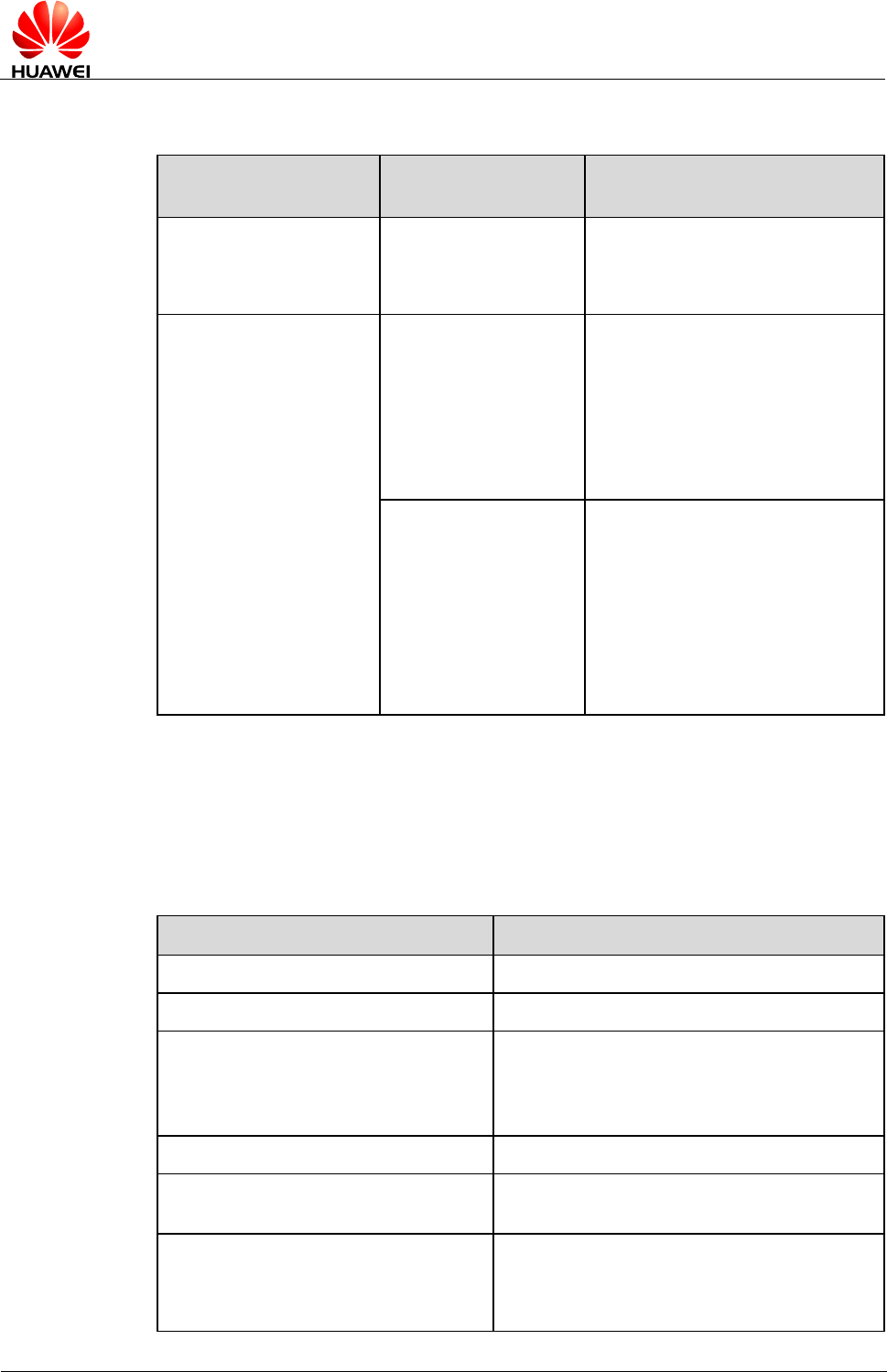
HUAWEI ME909s Series LTE Module
Application Guide
Internal Protocol Stack Application
Scenarios-TCP/UDP
Issue 04 (2017-12-11)
Huawei Proprietary and Confidential
Copyright © Huawei Technologies Co., Ltd.
37
5.2.2 Troubleshooting
Scenario
Possible Error
Information
Solution
Query the obtained IP and
DNS addresses.
AT^IPINIT?
^IPINIT: 0
OK
Initialization has not been
performed. Initialize the internal
protocol stack and query again.
Initialize the internal
protocol stack.
AT^IPINIT="1234","c
ard","card"
+CME ERROR:
Normal error
Initialization failed.
1. Check that the current network
signal strength is good and the
parameters are set correctly.
2. Ensure that no IP stack
termination command has been
executed.
+CME ERROR: The
link has been
established already
AT^IPINIT? queries whether the
internal protocol stack has been
initialized. If the internal protocol
stack has been initialized, it does
not need to be initialized again. If it
has not been initialized, there are
ongoing dial-up services. Hang up
the dial-up services and re-send
AT^IPINIT to start initialization.
5.3 Creating a Listen Server
5.3.1 Reference Process
Command
Description
AT^IPINIT="1234","card","card"
Initializes the internal protocol stack.
OK
AT^IPLISTEN="TCP",5000
Creates a TCP server whose listen port number
is 5000 (users can specify this number as
required). For the method to create UDP
servers, refer to the AT command document.
OK
AT^IPLISTEN?
Queries the information about the server that
has been created.
^IPLISTEN: "TCP",5000,5
OK

HUAWEI ME909s Series LTE Module
Application Guide
Internal Protocol Stack Application
Scenarios-TCP/UDP
Issue 04 (2017-12-11)
Huawei Proprietary and Confidential
Copyright © Huawei Technologies Co., Ltd.
38
- Only one server is supported by the internal protocol stack.
- The internal protocol stack must be initialized before you create a listen server.
5.3.2 Troubleshooting
Scenario
Possible Error
Information
Solution
Create a listen server.
AT^IPLISTEN="TCP",
5000
+CME ERROR: The network
has not been opened yet
Run AT^IPINIT to
initialize the internal
protocol stack, and then
create the listen server.
+CME ERROR: The server
has been established already
A listen server already
exists. Run
AT^IPCLOSE=6 to close
the existing listen server.
+CME ERROR: Fail to bind
the specified port with server
The local port is in use.
Change the port and re-send
the command.
5.4 Creating TCP/UDP Links
5.4.1 Reference Process
Command
Description
AT^IPINIT="1234","card","card"
Initializes the internal protocol stack.
OK
AT^IPOPEN=1,"UDP","192.168.44.33",
5000,5500
Uses a specified IP address to connect to the
remote server and establish a UDP link.
OK
AT^IPOPEN?
Queries link information.
^IPOPEN: 1,"UDP",5500,"192.168.44.33",5000,3,0
OK
AT^IPOPEN=1,"TCP","example.com",
80
Uses a specified domain name to connect to
the remote server and establish a TCP link.
OK
AT^IPOPEN?
Queries link information.

HUAWEI ME909s Series LTE Module
Application Guide
Internal Protocol Stack Application
Scenarios-TCP/UDP
Issue 04 (2017-12-11)
Huawei Proprietary and Confidential
Copyright © Huawei Technologies Co., Ltd.
39
Command
Description
^IPOPEN: 1,"TCP",5500,"example.com",80
OK
- When creating a listen server, the local port number can be ignored. If the port number is ignored,
the module will randomly assign a local port number.
- When creating a TCP link, ensure that the remote server has been started.
- The Maximum Segment Size (MSS) for creating TCP links is 1220 bytes. Data larger than the MSS
will be segmented into several packets.
5.4.2 Troubleshooting
Scenario
Possible Error
Information
Solution
Create a client link
AT^IPOPEN=1,"TCP","
192.168.44.33",5000
+CME ERROR: The
network has not been opened
yet
Initialize the internal
protocol stack before
sending the command to
create the link.
+CME ERROR: The link has
been established already
Run AT^IPCLOSE to
close the corresponding link.
Alternatively, change the
link ID and send the
command to create the link.
+CME ERROR: Fail to bind
the specified port
Change the local port
number, or leave the local
port number blank.
Query link information
AT^IPOPEN?
OK
No link information is
available. Create a link, or
accept the link as a server,
and then query the link
information again.
5.5 Sending Data
5.5.1 Reference Process
Command
Description
AT^IPINIT="1234","card","card"
Initializes the internal protocol stack.
OK

HUAWEI ME909s Series LTE Module
Application Guide
Internal Protocol Stack Application
Scenarios-TCP/UDP
Issue 04 (2017-12-11)
Huawei Proprietary and Confidential
Copyright © Huawei Technologies Co., Ltd.
40
Command
Description
AT^IPOPEN=1,"TCP","192.168.44.33",
5000,5500
Creates a link.
OK
AT^IPSEND=1,"31323334"
Sends data. In this example, 31323334 is
sent.
^IPSEND: 1
OK
^IPDATA: 1,8,31323334
Data is successfully sent and received.
AT^IPSENDEX=1,0,"31323334"
Sends data in mode 0. In this example,
31323334 is sent.
^IPSENDEX: 1
OK
^IPDATA: 1,8,31323334
AT^IPSENDEX=1,1,"31323334"
Sends data in mode 1. In this example, 1234
is actually sent.
^IPSENDEX: 1
OK
^IPDATA: 1,4,1234
AT^IPSENDEX=1,2,<datalen>
Sends data in mode 2.
OK
(Wait for the user to enter user data with a length of <datalen>)
^IPSENDEX: 1
OK
- AT^IPSEND and mode 0 of AT^IPSENDEX can send displayable characters only. Mode 1 and
mode 2 of AT^IPSENDEX can send all characters.
- In mode 2 of AT^IPSENDEX (length restriction mode), except the port that receives data entered
by the user, all other ports are unavailable before the user finishes entering the user data.

HUAWEI ME909s Series LTE Module
Application Guide
Internal Protocol Stack Application
Scenarios-TCP/UDP
Issue 04 (2017-12-11)
Huawei Proprietary and Confidential
Copyright © Huawei Technologies Co., Ltd.
41
5.5.2 Troubleshooting
Scenario
Possible Error
Information
Solution
Send data using
AT^IPSEND
AT^IPSEND=1,"data"
+CME ERROR: The
network has not been
opened yet
Before sending data,
initialize the protocol stack
or accept the link as a
server.
+CME ERROR: Remain
data is sending
The module is exiting
transparent transmission
mode and cannot send data.
Wait until the module
completely exits transparent
transmission mode.
+CME ERROR: The link
has not been established yet
Before sending data, create
a link or accept the link as a
server.
+CME ERROR: Normal
error
The module failed to send
the data. Ensure that the
current network's signal
strength is good.
Send data using mode 2 of
AT^IPSENDEX
AT^IPSENDEX=1,2,<data
len>
+CME ERROR: Too many
data to be sent
The length of the data
entered by the user exceeds
the length specified by the
command. Ensure that the
length of the data is equal to
the data length specified by
mode 2 of
AT^IPSENDEX.
5.6 Closing TCP/UDP Links
5.6.1 Reference Process
Command
Description
AT^IPCLOSE=<link_id>
Closes the specified link, server, or network. For details
about the parameters, refer to the related AT command
document.
OK
AT^IPCLOSE?
Queries the current link status.

HUAWEI ME909s Series LTE Module
Application Guide
Internal Protocol Stack Application
Scenarios-TCP/UDP
Issue 04 (2017-12-11)
Huawei Proprietary and Confidential
Copyright © Huawei Technologies Co., Ltd.
42
Command
Description
^IPCLOSE: 1,0,0,0,0
OK
1 indicates that the link is open, and 0 indicates that the
link is closed.
5.6.2 Troubleshooting
Scenario
Possible Error
Information
Solution
Close the specified link.
AT^IPCLOSE=<link_id>
+CME ERROR: Normal
error
The command is terminated.
Run the AT^IPCLOSE
command again.
5.7 Transparent Transmission Mode
5.7.1 Reference Process
Command
Description
AT^IPINIT="1234","card","card"
Initializes the internal protocol stack.
OK
AT^IPOPEN=1,"UDP","192.168.44.33"
,5000,5500
Creates a link.
OK
AT^IPCFL=12,0
Sets the transparent transmission mode to
time- and length-based transmission mode.
OK
AT^IPCFL=5,100
Sets the timer for triggering transparent
transmission to 10s (100 x 0.1s).
OK
AT^IPCFL=10,1220
Sets the TCP/UDP MSS to 1220 bytes.
OK
AT^IPENTRANS=1
Enables transparent transmission mode.
OK

HUAWEI ME909s Series LTE Module
Application Guide
Internal Protocol Stack Application
Scenarios-TCP/UDP
Issue 04 (2017-12-11)
Huawei Proprietary and Confidential
Copyright © Huawei Technologies Co., Ltd.
43
Command
Description
313233347D5D7D5E7E
Sends user data. User data is sent once the
data length reaches the segment length
specified by parameter 10 of AT^IPCFL. If
the user data length is shorter than the
specified length, the data will be sent when
the timer set by parameter 5 of AT^IPCFL
counts down to 0. For details about the
transmission mechanism, refer to the
description of AT^IPENTRANS in the AT
command document.
In this example, the data entered by the user
is 313233347D5D7D5E7E in hexadecimal
format.
The data sent by the module is the original
data entered by the user.
313233347D5D7D5E7E
Receives user data in time-based and
length-based transmission mode. In this
example, the data received by the module is
313233347D5D7D5E7E.
The original data received by the module is
presented.
+++
Exits transparent transmission mode. For the
rules about the +++ sequence, refer to the AT
command document.
OK
AT^IPCFL=12,1
Sets the transparent transmission mode to 7E
detection mode.
OK
AT^IPENTRANS=1
Enables transparent transmission mode.
OK
AT^IPENTRANS?
Queries the link ID for entering transparent
transmission mode from a non-transparent
port.
^IPENTRANS: 1
313233347D5D7D5E7E
Sends data in 7E detection mode (applies to
UDP only). In this example, the data that the
user wants to send is 313233347D7E in
hexadecimal format. Therefore, the user
needs to transform 7D to 7D5D and 7E to
7D5E, and adds 7E as the ending characters
to the end of the data.
After the module recognizes the data packet,
the data actually sent by the module is
313233347D7E.

HUAWEI ME909s Series LTE Module
Application Guide
Internal Protocol Stack Application
Scenarios-TCP/UDP
Issue 04 (2017-12-11)
Huawei Proprietary and Confidential
Copyright © Huawei Technologies Co., Ltd.
44
Command
Description
313233347D5D7D5E7E
Receives data in 7E detection mode (applies
to UDP only).
The data received by the module is
313233347D7E in hexadecimal format. After
receiving the data, the module transforms 7D
to 7D5D and 7E to 7D5E, and adds 7E as the
ending characters to the end of the data
before presenting the data to the user.
- The transparent transmission mode of the internal protocol stack supports UART only.
- The internal protocol stack allows only one link to enter transparent transmission mode. In addition,
before entering transparent transmission mode, ensure that only one link exists at the current
physical port. If the module functions as a server, the link can enter transparent transmission mode
only when the link is requested by a remote client and accepted by the server.
- The settings (including the time-based and length-based transmission mode and 7E detection mode)
of transparent transmission mode must be configured using AT^IPCFL before the transparent
transmission mode is enabled. For details about how to configure the settings, refer to the AT
command document.
- When in transparent transmission mode, the current port cannot be used for reporting.
5.7.2 Troubleshooting
Scenario
Possible Error
Information
Solution
Enter transparent
transmission mode.
AT^IPENTRANS=1
+CME ERROR: Invalid port
for transparent mode
This indicates that the link is
not established at a UART
port. To solve this problem,
establish a link from a
UART port and set the
UART port to enter
transparent transmission
mode.
+CME ERROR: More than
one link in physical port
There are more than one
link. Use AT^IPCLOSE to
close other links before
entering transparent
transmission mode.
+CME ERROR: The
physical port is in listen
state and has no client
The module functions as the
server but does not accept
the link requested by the
client. Accept the link
before entering transparent
transmission mode.

HUAWEI ME909s Series LTE Module
Application Guide
Internal Protocol Stack Application
Scenarios-TCP/UDP
Issue 04 (2017-12-11)
Huawei Proprietary and Confidential
Copyright © Huawei Technologies Co., Ltd.
45
Scenario
Possible Error
Information
Solution
Specify the transparent
transmission mode using
AT^IPCFL.
AT^IPCFL=5,10
+CME ERROR: Forbidden
operation in transparent
mode
AT^IPCFL cannot be used
during transparent
transmission. Exit
transparent transmission
mode before running
AT^IPCFL.
5.8 Packet Statistics
5.8.1 Reference Process
Command
Description
AT^IPFLOWQ?
Queries packet statistics. In this example, the returned
result indicates that 3 bytes of characters are successfully
received by and sent from link 1. For details about the
parameters, refer to the AT command document.
^IPFLOWQ: 1,3,3,3,3,3
^IPFLOWQ: 2,0,0,0,0,0
^IPFLOWQ: 3,0,0,0,0,0
^IPFLOWQ: 4,0,0,0,0,0
^IPFLOWQ: 5,0,0,0,0,0
OK
AT^IPFLOWQ=<linkid>
Clears the traffic statistics on the specified link (<linkid>:
1-5).
OK
AT^IPFLOWQ=0
Clears the traffic statistics on all links.
OK
5.9 TCP/UDP Link Change Indication
5.9.1 Reference Process
Command
Description
AT^IPINIT="1234","card","card"
Initializes the internal protocol stack.

HUAWEI ME909s Series LTE Module
Application Guide
Internal Protocol Stack Application
Scenarios-TCP/UDP
Issue 04 (2017-12-11)
Huawei Proprietary and Confidential
Copyright © Huawei Technologies Co., Ltd.
46
Command
Description
OK
AT^IPLISTEN="TCP",5000
Creates a server.
OK
(The client requests to connect to the
server.)
^IPSTATE: 1,1,1
The server accepts the link requested by the
client.
(The other party of the link closest the link.)
^IPSTATE: 1,0,0
(Network connection is broken.)
^IPSTATE: 1,0,2
^IPSTATE: 6,0,2
^IPSTATE: 7,0,2
^IPSTATE: 0,0,3
^IPSTATE: 0,0,4
Indications presented without solicitation for
broken links, connection to the server, and
network connections.
The number of current links has reached the
supported maximum. New link requests will be
rejected.
The module rejects new link requests because
it functions as the server and is in transparent
transmission mode.

HUAWEI ME909s Series LTE Module
Application Guide
Internal Protocol Stack Application
Scenarios-FTP
Issue 04 (2017-12-11)
Huawei Proprietary and Confidential
Copyright © Huawei Technologies Co., Ltd.
47
6 Internal Protocol Stack Application
Scenarios-FTP
6.1 Creating an FTP Control Link
6.1.1 Reference Process
Command
Description
AT^IPOPEN=1,"FTP","192.168.63.41",
21,,"username","password"
Creates a normal FTP control link, an FTP
user is successfully logged in FTP server.
OK
^IPSRVST: 1,10,230
- Only one FTP service can be enabled at a time. Not concurrent operate with other built-in protocols,
including TCP, UDP, etc.
- PDP must be activated.
- Please use FTPS because FTPS have a stronger security level than FTP.
6.1.2 Troubleshooting
Scenario
Possible Error
Information
Solution
Create the link.
AT^IPOPEN=1,"FTP","1
92.168.63.41",21,,"userna
me","password"
+CME ERROR: The
network has not been
opened yet
Initialize the internal
protocol stack before
sending the command to
create the link.
+CME ERROR: The link
has been established
already
Try to open an already
established link.

HUAWEI ME909s Series LTE Module
Application Guide
Internal Protocol Stack Application
Scenarios-FTP
Issue 04 (2017-12-11)
Huawei Proprietary and Confidential
Copyright © Huawei Technologies Co., Ltd.
48
6.2 Configuring Data Transmission Mode
In FTP, data can be transferred (PUT or GET) in three different modes.
- Transparent transmission mode:
For GET operation, files will be downloaded from the server and the content will be
displayed to the user.
For PUT operation, users shall enter the data to be transferred to the server followed by
"+++" to indicate the end of file.
During the data transfer process, we cannot execute other AT commands.
- Command transmission mode:
For GET operation, contents of downloaded file from server will be displayed to users
through AT^IPDATA report.
For PUT operation, users shall enter the data to be transferred using AT^IPSENDEX
command
During the data transfer process, we can execute any other AT commands than GET and
PUT.
- Buffer mode:
For GET operation, contents of downloaded file from server will be stored in a buffer.
And an ^IPRCVST report will be displayed which indicates whether there is data to be
read. After that, users need to issue "AT^IPRCV=<link_id>,<reqReceiveLength>" to
read the data from buffer. For more information on AT^IPRCV, please refer AT
command document.
The size of the buffer is 65536 bytes.
PUT operation will be similar as in COMMAND TRANSMISSION MODE.
During the data transfer process, we can execute any other AT commands other than
GET and PUT.
6.2.1 Reference Process
Command
Description
AT^IPCFL=14,0
Sets data transmission mode to transparent transmission mode.
OK
AT^IPCFL=14,1
Sets data transmission mode to command transmission mode.
OK
AT^IPCFL=14,2
Sets data transmission mode to buffer transmission mode.
OK
The AT^IPCFL command is used to set the processing mode for FTP file data. By default,
transparent transmission mode will be set. Users can change the data transmission mode as
per the need specified in section 6.2 Configuring Data Transmission Mode.

HUAWEI ME909s Series LTE Module
Application Guide
Internal Protocol Stack Application
Scenarios-FTP
Issue 04 (2017-12-11)
Huawei Proprietary and Confidential
Copyright © Huawei Technologies Co., Ltd.
49
6.3 Configuring FTP Data Channel Mode
6.3.1 Reference Process
Command
Description
AT^FTPCMD=1,PORT
Configures the connection mode in PORT mode for
downloading and uploading data.
OK
AT^FTPCMD=1,PASV
Configures the connection mode in PASV mode for
downloading and uploading data. The default mode is PASV
mode.
OK
- In PORT mode, the client creates the control channel and provides the data port number
which it will be listening on. The server then creates the data channel with the client
provided port.
- In PASV mode, the client creates both control channel and data channel. PASV mode is
generally used in scenarios where the server will not be able to setup the data channel;
one of the major reasons for this would be the network firewall limitation.
6.4 Getting FTP File Size
6.4.1 Reference Process
Command
Description
AT^FTPCMD=1,FILESIZE,"ftp.txt"
Gets the size of the file.
^FTPCMD: "FILESIZE",25490
OK
AT^FTPCMD=1,FILESIZE,"/work/test.txt"
Gets the size of the file.
^FTPCMD: "FILESIZE",34570
OK

HUAWEI ME909s Series LTE Module
Application Guide
Internal Protocol Stack Application
Scenarios-FTP
Issue 04 (2017-12-11)
Huawei Proprietary and Confidential
Copyright © Huawei Technologies Co., Ltd.
50
6.4.2 Troubleshooting
Scenario
Possible Error
Information
Solution
File Size Command
AT^FTPCMD=1,FILESIZ
E,"ftp.txt"
+CME ERROR: The link
has not been established
yet
Make sure that the file size
operation link ID is
established.
Get File Size for a big file
(> 4GB)
AT^FTPCMD=1,FILESIZ
E,"ftp.rar"
ERROR
The file size command will
return ERROR if the file
size is greater than 4 GB.
6.5 Downloading File Using "GET" Command in
Transparent Mode
6.5.1 Reference Process
Command
Description
AT^IPINIT="example.com"
Initializes the internal protocol stack.
OK
AT^IPCFL=14,0
Sets data transmission mode to transparent
mode. By default it will be in transparent
mode only.
OK
AT^IPOPEN=1,"FTP","192.168.63.41",
21,,"username","password"
Creates the link.
OK
^IPSRVST: 1,10,230
AT^FTPCMD=1,PORT
Sets the FTP data channel mode to PORT
mode for downloading and uploading the
data. By default it will be PASV mode.
OK
AT^FTPCMD=1,GET,"ftp.txt"
Gives the FTP GET command for
downloading data.

HUAWEI ME909s Series LTE Module
Application Guide
Internal Protocol Stack Application
Scenarios-FTP
Issue 04 (2017-12-11)
Huawei Proprietary and Confidential
Copyright © Huawei Technologies Co., Ltd.
51
Command
Description
CONNECT
Hello
OK
^IPSRVST: 1,11,1
6.5.2 Troubleshooting
Scenario
Possible Error
Information
Solution
AT^FTPCMD=1,GET,"ft
p.txt"
+CME ERROR: The link
has not been established
yet
Make sure that the get
operation link ID is
established.
6.6 Downloading File Using "GET" Command in
Command Mode
6.6.1 Reference Process
Command
Description
AT^IPINIT="example.com"
Initializes the internal protocol stack
OK
AT^IPOPEN=1,"FTP","192.168.63.41",
21,,"username","password"
Creates the link.
OK
^IPSRVST: 1,10,230
AT^IPCFL=14,1
Sets data transmission mode to command
mode.
OK
AT^FTPCMD=1,PORT
Sets the FTP data channel mode to PORT
mode for downloading and uploading the
data. By default it will be PASV mode.
OK

HUAWEI ME909s Series LTE Module
Application Guide
Internal Protocol Stack Application
Scenarios-FTP
Issue 04 (2017-12-11)
Huawei Proprietary and Confidential
Copyright © Huawei Technologies Co., Ltd.
52
Command
Description
AT^FTPCMD=1,GET,"ftp.txt"
Gives the FTP GET command for
downloading data.
OK
^IPDATA: 1, 5, Hello
^IPSRVST: 1,11,1
6.7 Download File Using "GET" Command in Buffer
Mode
6.7.1 Reference Process
Command
Description
AT^IPINIT="example.com"
Initializes the internal protocol stack.
OK
AT^IPOPEN=1,"FTP","192.168.63.41",
21,,"username","password"
Creates the link.
OK
^IPSRVST: 1,10,230
AT^IPCFL=14,2
Sets data transmission mode to buffer mode.
OK
AT^FTPCMD=1,PORT
Sets the FTP data channel mode PORT for
downloading and uploading the data. By
default it will be PASV mode. For more
information on when to use PORT or PASV
mode refer section 6.3 Configuring FTP
Data Channel Mode.
OK
AT^FTPCMD=1,GET,"ftp.txt"
Gives the FTP GET command for
downloading data.

HUAWEI ME909s Series LTE Module
Application Guide
Internal Protocol Stack Application
Scenarios-FTP
Issue 04 (2017-12-11)
Huawei Proprietary and Confidential
Copyright © Huawei Technologies Co., Ltd.
53
Command
Description
OK
^IPRCVST: 1, 1
^IPSRVST: 1,11,1
AT^IPRCV=1,5
Receives the data stored in the buffer.
^IPRCV: 1,5
Hello
OK
6.8 Uploading File Using "PUT" Command in Transparent
Mode
6.8.1 Reference Process
Command
Description
AT^IPINIT="example.com"
Initializes the internal protocol stack.
OK
AT^IPOPEN=1,"FTP","192.168.63.41",
21,,"username","password"
Creates the link.
OK
^IPSRVST: 1,10,230
AT^IPCFL=14,0
Sets data transmission mode to transparent
mode.
OK
AT^FTPCMD=1,PORT
Sets the FTP data channel mode PORT for
downloading and uploading the data. By
default it will be PASV mode. For more
information on when to use PORT or PASV
mode refer section 6.3 Configuring FTP
Data Channel Mode.
OK

HUAWEI ME909s Series LTE Module
Application Guide
Internal Protocol Stack Application
Scenarios-FTP
Issue 04 (2017-12-11)
Huawei Proprietary and Confidential
Copyright © Huawei Technologies Co., Ltd.
54
Command
Description
AT^FTPCMD=1,PUT,"ftp.txt"
Upload the data using this command. After
completion of uploading, send +++ to
terminate from the server.
Any character is forbidden in 900 ms before
and after inputting "+++", and it must be
less than 900 ms between two '+' input.
CONNECT
<Enter the data>
<Type "+++" to terminate from the server>
OK
^IPSRVST: 1,11,1
6.9 Uploading File Using "PUT" Command in Command
Mode and Buffer Mode
There is no difference in PUT operation of "Command and Buffer mode". In both the mode,
AT^IPSENDEX is used to enter the data.
6.9.1 Reference Process
Command
Description
AT^IPINIT="example.com"
Initializes the internal protocol stack.
OK
AT^IPOPEN=1,"FTP","192.168.63.41",
21,,"username","password"
Creates the link.
OK
^IPSRVST: 1,10,230
AT^IPCFL=14,2
Sets data transmission mode to buffer mode.
OK
AT^FTPCMD=1,PORT
Sets the FTP data channel mode PORT for
downloading and uploading the data. By
default it will be PASV mode. For more
information on when to use PORT or PASV
mode refer section 6.3 Configuring FTP
Data Channel Mode.

HUAWEI ME909s Series LTE Module
Application Guide
Internal Protocol Stack Application
Scenarios-FTP
Issue 04 (2017-12-11)
Huawei Proprietary and Confidential
Copyright © Huawei Technologies Co., Ltd.
55
Command
Description
OK
AT^FTPCMD=1,PUT,"ftp.txt"
Uploads the data using this command.
OK
AT^IPSENDEX=1,2,1500,0
It can send maximum 1500 data at a time.
The last parameter <eof> is 0 where 0
means user can send more data.
OK
<Enter the data>
^IPSENDEX: 1
OK
AT^IPSENDEX=1,2,1500,1
It can send maximum 1500 data at a time.
The last parameter <eof> is 1, where 1
means end of packet and the file upload will
be completed.
OK
<Enter the data>
^IPSENDEX: 1
OK
^IPSRVST: 1,11,1
AT^IPCLOSE=1
Closes the link.
OK
6.10 FTP Error Codes
<state code>
<state code> representative's meaning
100
The server has not responded
110
Restarts the mark reply
120
Prepares in n minutes
125
The connection opens the preparation to transmit
150
Opens the data connection
200
Command Execution Success

HUAWEI ME909s Series LTE Module
Application Guide
Internal Protocol Stack Application
Scenarios-FTP
Issue 04 (2017-12-11)
Huawei Proprietary and Confidential
Copyright © Huawei Technologies Co., Ltd.
56
<state code>
<state code> representative's meaning
202
Command Execution Failure
211
System Status
212
List Status
213
FILE SIZE
214
Help information
215
Name system type
220
The new client prepared
221
Service closure pilot connection, may
withdraw registers
225
The data connection opens, does not have the transmission to be in
progress
226
That the closure data connection, requested file operation successfully
227
Enters the passive pattern
230
Successful Login
250
File operation of request completes
257
Setup PATH NAME
331
A user correctness, needs the password
332
When registers needs the account information
350
Next order
421
Cannot provide the service, closes the pilot connection
425
Cannot open the data connection
426
The closure connection, stops transmitting

HUAWEI ME909s Series LTE Module
Application Guide
Internal Protocol Stack Application
Scenarios-HTTP
Issue 04 (2017-12-11)
Huawei Proprietary and Confidential
Copyright © Huawei Technologies Co., Ltd.
57
7 Internal Protocol Stack Application
Scenarios-HTTP
7.1 Creating an HTTP Server Link
7.1.1 Reference Process
Command
Description
AT^IPOPEN=1,"HTTP","m2m.example
.com",9001
Opens a normal HTTP server link, an HTTP
user is successfully logged in HTTP.
OK
- Only one HTTP service can be enabled at a time.
- Before an HTTP service is enabled, Internet configuration and HTTP configuration must be
completed.
- Please use HTTPS because HTTPS has stronger security level than HTTP.
7.1.2 Troubleshooting
Scenario
Possible Error
Information
Solution
Create the link.
AT^IPOPEN=1,"HTTP",
"m2m.example.com",9001
+CME ERROR: The
network has not been
opened yet
Initialize the internal
protocol stack before
sending the command to
create the link.
+CME ERROR: The link
has been established
already
Try to open an already
established link.

HUAWEI ME909s Series LTE Module
Application Guide
Internal Protocol Stack Application
Scenarios-HTTP
Issue 04 (2017-12-11)
Huawei Proprietary and Confidential
Copyright © Huawei Technologies Co., Ltd.
58
7.2 Configuring Data Transmission Mode
7.2.1 Reference Process
Command
Description
AT^IPCFL=14,0
Sets data transmission mode to transparent transmission mode.
OK
AT^IPCFL=14,1
Sets data transmission mode to command transmission mode.
OK
AT^IPCFL=14,2
Sets data transmission mode to buffer transmission mode.
OK
The AT^IPCFL command is used to set the data processing mode for HTTP, which is same
as FTP. By default, transparent transmission mode will be set. Users can change the data
transmission mode as per the need specified in section 6.2 Configuring Data Transmission
Mode.
7.3 Downloading File Using "GET" Command in
Transparent Mode
7.3.1 Reference Process
Command
Description
AT^IPINIT="example.com"
Initializes the internal protocol stack.
OK
AT^IPOPEN=1,"HTTP","192.168.63.41
",9001
Creates the link.
OK
AT^IPCFL=14,0
Sets data transmission mode to transparent
mode. By default it will be in transparent
mode only.
OK
AT^HTTPCMD=1,GET,"http://192.168.
63.41:9001/n_index.txt"
Downloads the file from the HTTP server
n_index.txt (In the following example,
<link_id>is 1).

HUAWEI ME909s Series LTE Module
Application Guide
Internal Protocol Stack Application
Scenarios-HTTP
Issue 04 (2017-12-11)
Huawei Proprietary and Confidential
Copyright © Huawei Technologies Co., Ltd.
59
Command
Description
CONNECT
hello123
OK
^IPSRVST: 1,12,200
7.3.2 Troubleshooting
Scenario
Possible Error
Information
Solution
AT^HTTPCMD=1,GET,"
http://m2m.example.com:9
001/n_index.html"
+CME ERROR: The link
has not been established
yet
Make sure that the get
operation link ID is
established.
7.4 Downloading File Using "GET" Command in
Command Mode
7.4.1 Reference Process
Command
Description
AT^IPINIT="example.com"
Initializes the internal protocol stack.
OK
AT^IPCFL=14,1
Sets data transmission mode to command
mode
OK
AT^IPOPEN=1,"HTTP","www.m2m.ex
ample.com",9001
Creates the link.
OK
AT^HTTPCMD=1,GET,"http://m2m.exa
mple.com:9001/n_index.txt"
Downloads the file from the HTTP server
n_index.txt (In the following example, link
ID is 1.

HUAWEI ME909s Series LTE Module
Application Guide
Internal Protocol Stack Application
Scenarios-HTTP
Issue 04 (2017-12-11)
Huawei Proprietary and Confidential
Copyright © Huawei Technologies Co., Ltd.
60
Command
Description
OK
^IPDATA: 1,5,hello123
^IPSRVST: 1,12,200
7.5 Downloading File Using "GET" Command in Buffer
Mode
7.5.1 Reference Process
Command
Description
AT^IPINIT="example.com"
Initializes the internal protocol stack.
OK
AT^IPOPEN=1,"HTTP","m2m.example
.com",9001
Creates the link.
OK
AT^IPCFL=14,2
Sets data transmission mode to buffer
transmission mode.
OK
AT^HTTPCMD=1,GET,"http://m2m.exa
mple.com:9001/n_index.txt"
Downloads the file from the HTTP server
n_index.txt (In the following example, link
ID is 1)
OK
^IPRCVST: 1,1
AT^IPRCV=1,5
Receives the data stored in the buffer.
^IPRCV: 1, 5
Hello
OK

HUAWEI ME909s Series LTE Module
Application Guide
Internal Protocol Stack Application
Scenarios-HTTP
Issue 04 (2017-12-11)
Huawei Proprietary and Confidential
Copyright © Huawei Technologies Co., Ltd.
61
7.6 Uploading File Using "POST" Command in
Transparent Mode
7.6.1 Reference Process
Command
Description
AT^IPINIT="example.com"
Initializes the internal protocol stack.
OK
AT^IPOPEN=1,"HTTP","m2m.example
.com",9001
Creates the link.
OK
AT^IPCFL=14,0
Sets data transmission mode to online mode.
OK
AT^HTTPCMD=1,POST,"HTTP://m2m.
example.com:448/cgi-bin/textarea.cgi",20
,"text/plain"
Uploads the data using this command .If the
upload has to be cancelled, then give +++ to
terminate.
CONNECT
textcontext=hello123
Enter 20 bytes of data
<phtml><head><title>Text Area - Fifth CGI
Program</title></phead><body><h2>EnteredText Content is
hello123</h2></body></html>
OK
^IPSRVST: 1, 12,200
7.7 Uploading File"POST" Command in Command Mode
and Buffer Mode
There is no difference in HTTP POST operation of "Command and Buffer mode". In both the
mode, AT^IPSENDEX is used to enter the data.
7.7.1 Reference Process
Command
Description
AT^IPINIT="example.com"
Initializes the internal protocol stack.
OK

HUAWEI ME909s Series LTE Module
Application Guide
Internal Protocol Stack Application
Scenarios-HTTP
Issue 04 (2017-12-11)
Huawei Proprietary and Confidential
Copyright © Huawei Technologies Co., Ltd.
62
Command
Description
AT^IPOPEN=1,"HTTP","m2m.example
.com",9001
Creates the link.
OK
AT^IPCFL=14,1
Sets data transmission mode to command
mode.
OK
AT^HTTPCMD=1,POST,"HTTP://m2m.
example.com:448/cgi-bin/textarea.cgi",20
,"text/plain"
Uploads the data content to the post script
textarea.cgi.
OK
AT^IPSEND=1,"textcontext=hello123"
Transmits the data through the link
established (in this case, <link_id> is 1).
^IPSEND: 1
OK
^IPSRVST: 1,12,200
AT^IPSENDEX=1,0,"textcontent=hello1
23"
Transmits the data through the link
established in IPSENDEX Mode 0 (in this
case, <link_id> is 1).
^IPSEND: 1
OK
^IPSRVST: 1,12,200
AT^IPSENDEX =1,2,20,1
textcontext=hello123
Transmits the data through the link
established in IPSENDEX Mode 2 (in this
case, <link_id> is 1).
^IPSEND: 1
OK
^IPSRVST: 1,12,200
AT^IPSENDEX=1,1,"74657874636F6E7
4656E743D68"
Transmits the data through the link
established in IPSENDEX Mode 1 (in this
case, <link_id> is 1)

HUAWEI ME909s Series LTE Module
Application Guide
Internal Protocol Stack Application
Scenarios-HTTP
Issue 04 (2017-12-11)
Huawei Proprietary and Confidential
Copyright © Huawei Technologies Co., Ltd.
63
Command
Description
^IPSEND: 1
OK
^IPSRVST: 1,12,200
AT^IPCLOSE=1
Closes the link.
OK
The <textcontent> specifies the corresponding field in the POST Script.
7.7.2 Troubleshooting
Scenario
Possible Error
Information
Solution
Close the specified link.
AT^IPCLOSE=<link_id>
+CME ERROR: Normal
error
The command is terminated.
Run the AT^IPCLOSE
command again.
Create the link.
AT^IPOPEN=1,"HTTP",
"m2m.example.com",9001
+CME ERROR: The
network has not been
opened yet
Initialize the internal
protocol stack before
sending the command to
create the link.
+CME ERROR: The link
has been established
already
Run AT^IPCLOSE to
close the corresponding link.
Alternatively, change the
link ID and send the
command to create the link.
+CME ERROR: Fail to
bind the specified port
Change the local port
number, or leave the local
port number blank.
Query link information.
AT^IPOPEN?
OK
No link information is
available. Create a link, or
accept the link as a server,
and then query the link
information again.
AT^HTTPCMD=?
^HTTPCMD:
(1-5),("GET","POST")
Get the current HTTP
command
AT^HTTPCMD=1,GET,"
http://m2m.example.com:9
001/n_index.html"
+CME ERROR: The link
has not been established
yet
Run AT^IPOPEN to open
the link and then perform
the download operation.

HUAWEI ME909s Series LTE Module
Application Guide
Internal Protocol Stack Application
Scenarios-HTTP
Issue 04 (2017-12-11)
Huawei Proprietary and Confidential
Copyright © Huawei Technologies Co., Ltd.
64
Scenario
Possible Error
Information
Solution
AT^HTTPCMD=1,POST,
"http://m2m.example.com:
9001/cgi-bin/textarea.cgi",
20,"text/index.html"
+CME ERROR: The link
has not been established
yet
Run AT^IPOPEN to open
the link and then perform
the upload operation.
7.8 HTTP Error Codes
<state code>
<state code> representative's meaning
200
Operation successful
301
Moved permanently
302
Moved temporarily
401
Requested action requires authorization
403
Forbidden
404
Resource not found
405
Method not allowed on resource
406
Requested representation not accepted
408
Request timed out
410
Requested source is no longer available server
500
Internal server error
501
Requested HTTP operation not supported
505
HTTP version not supported

HUAWEI ME909s Series LTE Module
Application Guide
Internal Protocol Stack Application
Scenarios-SMTP
Issue 04 (2017-12-11)
Huawei Proprietary and Confidential
Copyright © Huawei Technologies Co., Ltd.
65
8 Internal Protocol Stack Application
Scenarios-SMTP
8.1 Creating an SMTP Server Link
8.1.1 Reference Process
Command
Description
AT^IPOPEN=1,"smtp","192.168.63.41",
25,,"m2mtest@m2m.example.com","M2
m"
An SMTP user is successfully logged in
SMTP.
OK
^IPSRVST: 1,13,235
- Only one SMTP service can be enabled at a time.
- Before an SMTP service is enabled, Internet configuration and SMTP configuration must be
completed.
- Please use SMTPS because SMTPS have a stronger security level than SMTP.
8.1.2 Troubleshooting
Scenario
Possible Error Information
Solution
Create the link.
AT^IPOPEN=1,"sm
tp","192.168.63.41",
25,,"m2mtest@m2m
.example.com","M2
m"
+CME ERROR: The network
has not been opened yet
Initialize the internal protocol
stack before sending the
command to create the link.
+CME ERROR: The link has
been established already
Try to open an already
established link.

HUAWEI ME909s Series LTE Module
Application Guide
Internal Protocol Stack Application
Scenarios-SMTP
Issue 04 (2017-12-11)
Huawei Proprietary and Confidential
Copyright © Huawei Technologies Co., Ltd.
66
8.2 Sending Mail Through "emsend" Without Attachment
8.2.1 Reference Process
Command
Description
AT^IPOPEN=1,"smtp","192.168.63.41",
25,,"m2mtest@m2m.example.com","M2
m"
Creates the link.
OK
^IPSRVST: 1,13,235
AT^EMSEND=1,"m2mtest@m2m.exam
ple.com","test with
attachment","utf-8",0
Sends mail without attachment.
>
<ENTER THE BODY OF THE MAIL>
<Press Ctrl+Z to end input>
OK
^IPSRVST: 1,14,250
8.3 Sending Mail Through "emsend" with Attachment
Using 7 bit
8.3.1 Reference Process
Command
Description
AT^IPOPEN=1,"smtp","192.168.63.41",25,,
"m2mtest@m2m.example.com","M2m"
Creates the link.
OK
^IPSRVST: 1,13,235
AT^EMSEND=1,"m2mtest@m2m.example.c
om","test with
attachment","utf-8",1,"test.txt"
Sends mail with attachment

HUAWEI ME909s Series LTE Module
Application Guide
Internal Protocol Stack Application
Scenarios-SMTP
Issue 04 (2017-12-11)
Huawei Proprietary and Confidential
Copyright © Huawei Technologies Co., Ltd.
67
Command
Description
>
<ENTER THE BODY OF THE MAIL>
<Press Ctrl+Z to end input>
OK
^IPSRVST: 1,14,250
AT^IPSENDEX=1,2,1500,0
It can send maximum 1500 data at a
time. The last parameter i.e. <eof> can
be 0 and 1, where 0 means user can
send more data and 1 means the last
data to be send. The Following is an
example on how to send 3000 bytes of
attachment.
^IPSENDEX: 1
OK
AT^IPSENDEX=1,2,1000,0
Here user has to send 1000 bytes of
data. The last parameter is 0, which
means not end of file.
^IPSENDEX: 1
OK
AT^IPSENDEX=1,2,500,1
Here user has to send 500 bytes of data.
The last parameter is 1, which means
end of file.
^IPSENDEX: 1
OK
^IPSRVST: 1,14,250

HUAWEI ME909s Series LTE Module
Application Guide
Internal Protocol Stack Application
Scenarios-SMTP
Issue 04 (2017-12-11)
Huawei Proprietary and Confidential
Copyright © Huawei Technologies Co., Ltd.
68
8.4 Sending Mail Through "emsend" with Attachment
Using base 64
8.4.1 Reference Process
Command
Description
AT^IPOPEN=1,"smtp","192.168.63.41",
25,,"m2mtest@m2m.example.com","M2
m"
Creates the link.
OK
^IPSRVST: 1,13,235
AT^EMSEND=1,"m2mtest@m2m.exam
ple.com","test with attachment",
"utf-8",2,"jpgtest.jpg"
Sends mail with attachment using base 64
algorithm.
>
<ENTER THE BODY OF THE MAIL>
<Press Ctrl+Z to send>
OK
^IPSRVST: 1,14,250
AT^IPSENDEX=1,2, 4,1
It can send maximum 1500 data at a time.
The last parameter i.e. <eof> can be 0 and 1,
where 0 means user can send more data and
1 means the last data to be send.
^IPSENDEX: 1
OK
^IPSRVST: 1,14,250
AT^IPCLOSE=1
Closes the link.
OK

HUAWEI ME909s Series LTE Module
Application Guide
Internal Protocol Stack Application
Scenarios-SMTP
Issue 04 (2017-12-11)
Huawei Proprietary and Confidential
Copyright © Huawei Technologies Co., Ltd.
69
8.4.2 Troubleshooting
Scenario
Possible Error
Information
Solution
Close the specified link.
AT^IPCLOSE=<link_id>
+CME ERROR: Normal
error
The command is terminated.
Run the AT^IPCLOSE
command again.
Create the link.
AT^IPOPEN=1,"smtp","
192.168.63.41",25,,"m2mte
st@m2m.example.com","
M2m"
+CME ERROR: The
network has not been
opened yet
Initialize the internal
protocol stack before
sending the command to
create the link.
+CME ERROR: The link
has been established
already
Run AT^IPCLOSE to
close the corresponding link.
Alternatively, change the
link ID and send the
command to create the link.
+CME ERROR: Fail to
bind the specified port
Change the local port
number, or leave the local
port number blank.
Query link information.
AT^IPOPEN?
OK
No link information is
available. Create a link, or
accept the link as a server,
and then query the link
information again.
AT^SMTPCMD=?
^HTTPCMD:
(1-5),("GET","POS")
Get the current HTTP
command.
AT^EMSEND=1,"m2mtes
t@m2m.example.com","te
st with attachment","ut
f-8",2,"test.txt"
+CME ERROR: The link
has not been established
yet
Run AT^IPOPEN to open
the link and then perform
the download operation.
8.5 SMTP Error Codes
<state code>
<state code> representative's meaning
235
Authentication successful
250
Its typical side message is "Requested mail action okay completed":
meaning that the server has transmitted a message.
354
The side message can be very cryptic ("Start mail input end
<CRLF>.<CRLF>"). It's the typical response to the DATA command.
421
The service is unavailable due to a connection problem: it may refer to an
exceeded limit of simultaneous connections, or a more general temporary
problem.

HUAWEI ME909s Series LTE Module
Application Guide
Internal Protocol Stack Application
Scenarios-SMTP
Issue 04 (2017-12-11)
Huawei Proprietary and Confidential
Copyright © Huawei Technologies Co., Ltd.
70
<state code>
<state code> representative's meaning
450
"Requested action not taken - The user's mailbox is unavailable". The
mailbox has been corrupted or placed on an offline server, or your email
hasn't been accepted for IP problems or blacklisting.
451
"Requested action aborted - Local error in processing". Your ISP's server
or the server that got a first relay from yours has encountered a connection
problem.
452
Too many emails sent or too many recipients: more in general, a server
storage limit exceeded.
500
A syntax error: the server couldn't recognize the command.
501
Another syntax error, not in the command but in its parameters or
arguments.
502
The command is not implemented.
503
The server has encountered a bad sequence of commands, or it requires an
authentication.
504
A command parameter is not implemented.
535
Authentication failure
550
It usually defines a non-existent email address on the remote side.
551
"User not local or invalid address - Relay denied". Meaning, if both your
address and the recipient's are not locally hosted by the server, a relay can
be interrupted.
552
"Requested mail actions aborted - Exceeded storage allocation": simply
put, the recipient's mailbox has exceeded its limits.
553
"Requested action not taken - Mailbox name invalid". That is, there's an
incorrect email address into the recipients line.
554
This means that the transaction has failed. It's a permanent error and the
server will not try to send the message again.
555
Syntax error

HUAWEI ME909s Series LTE Module
Application Guide
Internal Protocol Stack Application
Scenarios-FTPS/HTTPS/SMTPS
Issue 04 (2017-12-11)
Huawei Proprietary and Confidential
Copyright © Huawei Technologies Co., Ltd.
71
9 Internal Protocol Stack Application
Scenarios-FTPS/HTTPS/SMTPS
9.1 Creating a Secure Control Link
9.1.1 Preliminary Operations
Before initializing a secure socket and transmitting data over the secure channel, certain
preliminary operations need to be performed which are mentioned below.
9.1.2 IP Configuration
SSL requires IP configurations to be done to access the secure server over which data can be
transmitted
- To Configure APN
Run:
AT+CGDCONT=1,"IP","example.com"
Response:
OK
- To check the APN settings
Run:
AT+CGDCONT?
Response:
+CGDCONT: 1,"IP","example.com","",0,0
OK
- To get the Signal Strength
Run:
AT+CSQ
Response:
+CSQ: 28,99
OK
31 is the strongest, 0 is the weakest, and 99 for
none.

HUAWEI ME909s Series LTE Module
Application Guide
Internal Protocol Stack Application
Scenarios-FTPS/HTTPS/SMTPS
Issue 04 (2017-12-11)
Huawei Proprietary and Confidential
Copyright © Huawei Technologies Co., Ltd.
72
- To get the registered network
Run:
AT+ COPS?
Response:
+COPS: 0,0,"Terminal MHA Net",2
OK
9.1.3 SSL and TLS
SSL and TLS are cryptographic protocols used over the Internet to provide secure data
communication in client server architecture.
9.1.4 Certificates
The SSL module allows the storage of a server certificate. It is assumed that licensed version
of SSL contains certificates that will be unique for each device.
9.2 Configuring SSL
9.2.1 Reference Process
FTPS
Command
Description
AT^IPINIT="example.com"
Initializes the internal protocol stack.
OK
AT^SSLEN=1,1,1
Enables a secure socket.
OK
AT^SSLCFG=1,30,0,1
Configures the properties of a secure socket.
OK
AT^IPOPEN=1,"FTPS","192.168.63.41"
,990,,"username","password"
Creates a secure FTP control link, an FTP
user is successfully logged in FTP server.
OK
^IPSRVST:1,10,230
GET and PUT operations are the same as in normal FTP.

HUAWEI ME909s Series LTE Module
Application Guide
Internal Protocol Stack Application
Scenarios-FTPS/HTTPS/SMTPS
Issue 04 (2017-12-11)
Huawei Proprietary and Confidential
Copyright © Huawei Technologies Co., Ltd.
73
HTTPS
Command
Description
AT^IPINIT="example.com"
Initializes the internal protocol stack.
OK
AT^SSLEN=1,1,1
Enables a secure socket.
OK
AT^SSLCFG=1,30,0,1
Configures the properties of a secure socket.
OK
AT^IPOPEN=1,"HTTPS","m2m.exam
ple.com",448
Creates a secure HTTP server link, an HTTP
user is successfully logged in HTTP server.
OK
GET and POST operations are the same as in normal HTTP
SMTPS
Command
Description
AT^IPINIT="example.com"
Initializes the internal protocol stack.
OK
AT^SSLEN=1,1,1
Enables a secure socket.
OK
AT^SSLCFG=1,30,0,1
Configures the properties of a secure socket.
OK
AT^IPOPEN=1,"smtps","192.168.63.41"
,25,,"m2mtest@m2m.example.com","M2
m"
Creates a secure SMTP server link, an
SMTP user is successfully logged in SMTP
server.
OK
^IPSRVST: 1,13,235
Sending emails (EMSEND) operation is the same as in normal SMTP.

HUAWEI ME909s Series LTE Module
Application Guide
SSL Application Scenarios
Issue 04 (2017-12-11)
Huawei Proprietary and Confidential
Copyright © Huawei Technologies Co., Ltd.
74
10 SSL Application Scenarios
10.1 Initializing Secure Services
10.1.1 Reference Process
Command
Description
AT^IPINIT="1234","card","card"
In this example provided in the left column,
the APN is 1234, and the user name and
password are both card.
OK
AT^SSLEN=1,1,1
Enables SSL
OK
AT^SSLEN?
Queries SSL enable status and obtained IP.
^SSLEN: 1,1,1,"192.168.200.1"
OK
AT^SSLEN=1,0
Disables SSL
OK
AT^SSLEN?
^SSLEN: 1,0,1,"0.0.0.0"
OK

HUAWEI ME909s Series LTE Module
Application Guide
SSL Application Scenarios
Issue 04 (2017-12-11)
Huawei Proprietary and Confidential
Copyright © Huawei Technologies Co., Ltd.
75
10.1.2 Troubleshooting
Scenario
Possible Error
Information
Solution
Disabling SSL
AT^SSLEN=0,0
+CME ERROR: Invalid
Operation
AT^SSLEN? queries the SSL
secure/normal socket enable status. If
secure socket is enabled, it is invalid
to disable normal socket and vice
versa.
Enabling SSL
AT^SSLEN=1,1
+CME ERROR: Socket not
enabled
Initialization has not been performed.
Initialize the internal protocol stack
and enable SSL.
+CME ERROR: Socket
already enabled
AT^SSLEN? queries the SSL enable
status. If SSL has been enabled, it
does not need to be enabled again.
10.2 Configuring SSL
10.2.1 Reference Process
Command
Description
AT^IPINIT="1234","card","card"
Initializes the internal protocol stack.
OK
AT^SSLEN=1,1,1
Enables SSL.
OK
AT^SSLCFG=1,60,0,1
Configures the timeout for TX and RX, cipher
suites to be sent and authentication mode.
OK
AT^SSLCFG?
Queries SSL configurations.
^SSLCFG: 1,10,1,0
OK
TLS_RSA_WITH_NULL_SHA and TLS_RSA_WITH_NULL_SHA256 have low safety coefficient. It
is recommended you choose other encryption algorithms. For details, please see HUAWEI ME909s
Series LTE Module AT Command Interface Specification.

HUAWEI ME909s Series LTE Module
Application Guide
SSL Application Scenarios
Issue 04 (2017-12-11)
Huawei Proprietary and Confidential
Copyright © Huawei Technologies Co., Ltd.
76
10.2.2 Troubleshooting
Scenario
Possible Error
Information
Solution
Create a client link
AT^SSLCFG=1,60,0,1
+CME ERROR: Invalid
Operation
Initialize the internal protocol
stack and enable SSL in
secure mode before
configuring the secure socket
link.
+CME ERROR: Invalid
Operation
It is not possible to configure
the socket after opening.
10.3 Managing Certificate/Key
10.3.1 Reference Process
Command
Description
AT^IPINIT="1234","card","card"
Initializes the internal protocol stack.
OK
AT^SSLEN=1,1,1
Enables SSL
OK
AT^SSLMNG=1,1,0,"ca-crt.pem",1,1,"L
S0tLS1CRUdJTiBDRVJUSUZJQ0FURS
0tLS0tDQotLS0tLUVORCBDRVJUSUZ
JQ0FURS0tLS0t"
Stores a certificate/key in the file system
OK
AT^SSLMNG=1,1,2,"ca-crt.pem"
Loads a certificate/key in to library
OK
AT^SSLMNG=1,1,1,"ca-crt.pem"
Deletes a certificate/key from the file
system.
OK
AT^SSLMNG?
Queries the last SSLMNG operation
performed and gives list of certificates
present in the file system.

HUAWEI ME909s Series LTE Module
Application Guide
SSL Application Scenarios
Issue 04 (2017-12-11)
Huawei Proprietary and Confidential
Copyright © Huawei Technologies Co., Ltd.
77
Command
Description
^SSLMNG:
1,ca-crt.pem
0,client-crt.pem
2,client-key.pem
1,2,"ca-crt.pem",2,3
OK
- If more than one client and key certificates are available in the file system, then users need to load
the corresponding certificate by using AT^SSLMNG command with the <action> as 2 (read data) to
succeed the hand shake during socket open.
- AT^SSLMNG for action 0 (store data) can store a maximum of 10 certificates (10 each for ca-cert,
client cert and client key) in file system beyond which it would display error "Certificate maximum
limit reached".
- AT^SSLMNG for action 2 (read data) can load a maximum of 10 certificates from buffer/file
system during a particular session beyond which it would display error "Certificate maximum limit
reached".
- AT^SSLMNG query command would display first 10 certificates stored in file system for each type
(CA, Client, Private Key) of certificates.
- Usage of <password> parameter is applicable in case of "Load" of "Private Key" during client
authentication and it is required to set the password if the private key is encrypted. So this password
parameter is an optional parameter.
- If SSL is enabled in ASCII data mode then the buffer should be 1024 bytes of raw data.
- <password> is applicable only if <action> is 2 and when loading the private key with password
- It is not required to give the password in every package, but the last package must contain the
correct password.
10.3.2 Troubleshooting
Scenario
Possible Error
Information
Solution
Manage a certificate
AT^SSLMNG=1,1,2,
"ca-crt.pem"
+CME ERROR: Invalid
Operation
Initialize the internal protocol
stack and enable SSL in secure
mode.
AT^SSLMNG?
^SSLMNG:
OK
After device reset or before any
SSLMNG operation is done, if
no certificates are present in the
file system.

HUAWEI ME909s Series LTE Module
Application Guide
SSL Application Scenarios
Issue 04 (2017-12-11)
Huawei Proprietary and Confidential
Copyright © Huawei Technologies Co., Ltd.
78
10.4 Creating SSL Links
10.4.1 Reference Process
Command
Description
AT^IPINIT="1234","card","card"
Initializes the internal protocol stack.
OK
AT^SSLEN=1,1,1
Enables SSL.
OK
AT^SSLO=1,"192.168.63.41",9900,1,60
Uses a specified IP address to connect to the
remote server and establish a SSL link. For
the method to create normal link, refer to
the AT command document.
OK
AT^SSLO=1,"example.com",9900,0,60
Uses a specified domain name to connect to
the remote server and establish a SSL link.
OK
AT^SSLO?
Queries link information.
^SSLO: 1,"192.168.63.41",9900,1,60
OK
10.4.2 Troubleshooting
Scenario
Possible Error
Information
Solution
Create a client link
AT^SSLO=1,"192.168.
63.41",9900,1,60
+CME ERROR: Socket not
enabled
Initialize the internal protocol
stack and enable SSL before
sending the command to create
the link.
+CME ERROR: Socket
already connected
Run AT^SSLC to close the
current link.
+CME ERROR: Invalid
Operation
Open the connection with the
same SSL id used in
AT^SSLEN, or disable SSL
and enable with the required
SSL id.

HUAWEI ME909s Series LTE Module
Application Guide
SSL Application Scenarios
Issue 04 (2017-12-11)
Huawei Proprietary and Confidential
Copyright © Huawei Technologies Co., Ltd.
79
10.5 Querying SSL Status
10.5.1 Reference Process
Command
Description
AT^IPINIT="1234","card","card"
Initializes the internal protocol stack.
OK
AT^SSLEN=1,1,1
Enables SSL.
OK
AT^SSLO=1,"192.168.63.41",9900,1,60
Creates a secure socket link
OK
AT^SSLSTAT=1
Queries connections status of secure/normal
socket
^SSLSTAT: Secure connection opened
OK
10.5.2 Troubleshooting
Scenario
Possible Error
Information
Solution
Create a client link
AT^SSLO=1,"192.168.63.
41",9900,1,60
+CME ERROR: Invalid
Operation
Initialize the internal
protocol stack and enable
SSL before sending the
command to create the link.
+CME ERROR: Invalid
Operation
Query the connection status
with the same SSL id used
in SSLEN, or disable SSL
and enable with the required
SSL id.
10.6 Sending Data
10.6.1 Reference Process
Command
Description
AT^IPINIT="1234","card","card"
Initializes the internal protocol stack.

HUAWEI ME909s Series LTE Module
Application Guide
SSL Application Scenarios
Issue 04 (2017-12-11)
Huawei Proprietary and Confidential
Copyright © Huawei Technologies Co., Ltd.
80
Command
Description
OK
AT^SSLEN=1,1,1
Enables SSL in base64 encoded data mode.
OK
AT^SSLO=1,"192.168.63.41",9900,1,60
Creates a secure socket link in
asynchronous mode
OK
AT^SSLTX=1,"aGVsbG8=",60
Sends data. In this example, base64 encode
data of "hello" i.e. "aGVsbG8=" is sent.
OK
^SSLRX: 5
aGVsbG8=
Data is successfully sent and received.
AT^SSLTX=1,"aGVsbG8=",60
Sends data in synchronous mode
OK
- If SSL is enabled in base64 encoded data mode then the buffer should be 768 bytes of raw data.
- If SSL is enabled in ASCII data mode then the buffer should be 1024 bytes of raw data.
10.6.2 Troubleshooting
Scenario
Possible Error
Information
Solution
Send data
AT^SSLTX=1,"aGVsbG8
=",60
+CME ERROR: Invalid
Operation
Before sending data,
initialize the protocol stack
and enable SSL.
+CME ERROR: Socket not
connected
Before sending data, create
a secure/normal socket link.
+CME ERROR: Invalid
Operation
Send data with the same
SSL id used in SSLEN, or
disable SSL and enable with
the required SSL id.

HUAWEI ME909s Series LTE Module
Application Guide
SSL Application Scenarios
Issue 04 (2017-12-11)
Huawei Proprietary and Confidential
Copyright © Huawei Technologies Co., Ltd.
81
10.7 Receiving Data
10.7.1 Reference Process
Command
Description
AT^IPINIT="1234","card","card"
Initializes the internal protocol stack.
OK
AT^SSLEN=1,1,1
Enables SSL in base64 encoded data mode
OK
AT^SSLO=1,"192.168.63.41",9900,1,60
Creates a secure socket link in
asynchronous mode
OK
AT^SSLTX=1,"aGVsbG8=",60
Sends data. In this example, base64 encode
data of "hello" i.e. "aGVsbG8=" is sent.
OK
^SSLRX: 5
aGVsbG8=
Data is successfully sent and received.
AT^SSLTX=1,"aGVsbG8=",60
Sends data in synchronous mode
OK
AT^SSLRX=1,10,60
Receives data in synchronous mode
^SSLRX: 5
aGVsbG8=
OK
If SSL is enabled in base64 encoded data mode then the length of the received data will differ from
displayed received data length, because the received data is in base64 encoded format.
10.7.2 Troubleshooting
Scenario
Possible Error
Information
Solution
Send data
AT^SSLRX=1,1024,60
+CME ERROR: Invalid
Operation
Before receiving data,
initialize the protocol stack
and enable SSL.
+CME ERROR: Socket not
connected
Before receiving data, create a
secure/normal socket link.

HUAWEI ME909s Series LTE Module
Application Guide
SSL Application Scenarios
Issue 04 (2017-12-11)
Huawei Proprietary and Confidential
Copyright © Huawei Technologies Co., Ltd.
82
Scenario
Possible Error
Information
Solution
+CME ERROR: Invalid
Operation
Receive data with the same
SSL id used in SSLEN, or
disable SSL and enable with
the required SSL id.
+CME ERROR: Invalid
Operation
If socket has been opened in
asynchronous mode, SSLRX
command is not allowed.
Open socket in synchronous
mode and receive data.
10.8 Closing SSL
10.8.1 Reference Process
Command
Description
AT^IPINIT="1234","card","card"
Initializes the internal protocol stack.
OK
AT^SSLEN=1,1,1
Enables SSL in base64 encoded data mode
OK
AT^SSLO=1,"192.168.63.41",9900,1,60
Creates a secure socket link
OK
AT^SSLC=1
Closes the link
OK
10.8.2 Troubleshooting
Scenario
Possible Error
Information
Solution
Closing socket
AT^SSLC=1
+CME ERROR: Invalid
Operation
Before closing the socket, initialize the
protocol stack and enable SSL.
+CME ERROR: Socket not
connected
Before closing the socket, create a
secure/normal socket link.
+CME ERROR: Invalid
Operation
Close the socket with the same SSL id
used in SSLO.

HUAWEI ME909s Series LTE Module
Application Guide
ECM Application Scenarios
Issue 04 (2017-12-11)
Huawei Proprietary and Confidential
Copyright © Huawei Technologies Co., Ltd.
83
11 ECM Application Scenarios
11.1 Dialing ECM
11.1.1 Reference Process
Command
Description
AT^NDISDUP=?
Checks the parameter range supported by the
command.
^NDISDUP: (1-11),(0-1)
OK
AT^NDISDUP=1,1,"1234"
Sets up a dial-up connection using the APN provided
by the network server. "1234" is an example.
OK
^NDISSTAT: 1,,,"IPV4"
The command is successfully executed.
Reports the dial-up connection state.
AT^NDISDUP=1,1,"4321","h
uawei","huawei",1
Sets up a dial-up connection using the account,
password, and authentication mode provided by the
network server.
OK
^NDISSTAT: 1,,,"IPV4"
The command is successfully executed.
Reports the dial-up connection state.
AT^NDISDUP=2,1,"1111"
Sets up the second dial-up connection using the APN
provided by the network server."1111" is an example
which is different from "1234".
OK
^NDISSTAT: 1,,,"IPV4"
The command is successfully executed.
Reports the dial-up connection state.

HUAWEI ME909s Series LTE Module
Application Guide
ECM Application Scenarios
Issue 04 (2017-12-11)
Huawei Proprietary and Confidential
Copyright © Huawei Technologies Co., Ltd.
84
Command
Description
AT^NDISDUP=2,1,"4321","h
uawei","huawei",1
Sets up the second dial-up connection using the
account, password, and authentication mode provided
by the network server.
OK
^NDISSTAT: 1,,,"IPV4"
The command is successfully executed.
Reports the dial-up connection state.
The process of obtaining the IP address:
1. After the dial-up is successful, the module will establish the DHCP service
automatically.
2. The PC driver will get the dial-up state and send <net_ready> state to the network
manage.
3. The network manager sends the DHCP service discover.
4. The module responses the service discover, and then sends the IP and DNS address
which is obtained from the PDP active process to the network managing device.
11.1.2 Troubleshooting
Scenario
Possible Error
Information
Solution
AT^NDISDUP=1,1,"1234
"
+CME ERROR: 10
+CME ERROR: SIM not
inserted
No SIM card is detected.
Insert a SIM card.
AT^NDISDUP=1,1,"4321
","huaei","huawei",1
OK
^NDISSTAT:
0,29,,"IPV4"
NDISEND indicates the
failure reason during the
dial-up.
29 indicates that the
authenticated information is
not correct.
AT^NDISDUP=1,1,"abcd
"
OK
^NDISSTAT:
0,33,,"IPV4"
NDISEND indicates the
failure reason during the
dial-up.
33 indicates that request
service is not subscribed.
In this case, the network don
not support this APN
"abcd".

HUAWEI ME909s Series LTE Module
Application Guide
ECM Application Scenarios
Issue 04 (2017-12-11)
Huawei Proprietary and Confidential
Copyright © Huawei Technologies Co., Ltd.
85
11.2 Querying the Dial-up Connection State
11.2.1 Reference Process
Command
Description
AT^NDISSTATQRY=1
Queries the first dial-up connection state.
^NDISSTATQRY: 0,,,"IPV4"
OK
Reports the connection is not set up.
^NDISSTATQRY: 1,,,"IPV4"
OK
Reports the connection is set up.
AT^NDISSTATQRY=2
Queries the second dial-up connection state.
^NDISSTATQRY: 0,,,"IPV4"
OK
Reports the connection is not set up
^NDISSTATQRY: 1,,,"IPV4"
OK
Reports the connection is set up.
11.2.2 Troubleshooting
None
11.3 Disconnecting the Dial-up Connection
11.3.1 Reference Process
Command
Description
AT^NDISDUP=1,0
Disconnects the first dial-up connection.
AT^NDISDUP=2,0
Disconnects the second dial-up connection.
OK
^NDISSTAT: 0,0,,"IPV4"
The command is successfully executed.
IPv4 changes from the connected state to the disconnected
state.

HUAWEI ME909s Series LTE Module
Application Guide
ECM Application Scenarios
Issue 04 (2017-12-11)
Huawei Proprietary and Confidential
Copyright © Huawei Technologies Co., Ltd.
86
11.3.2 Troubleshooting
None

HUAWEI ME909s Series LTE Module
Application Guide
Voice and Supplementary Service
Application Scenarios
Issue 04 (2017-12-11)
Huawei Proprietary and Confidential
Copyright © Huawei Technologies Co., Ltd.
87
12 Voice and Supplementary Service
Application Scenarios
12.1 Pre-configuration
12.1.1 Reference Process
Command
Description
AT^CPCM=0,0,0,0,0
or
AT^CPCM=2,0,0,0,0
Sets the PCM voice channel as the master mode.
Sets the PCM voice channel as the slave mode.
(Only the MASTER_PRIM mode and the SLAVE mode are
supported.)
OK
AT^SMUT=0
Unmutes the receive channel.
OK
12.2 Voice Call Handling
12.2.1 Reference Process
Command
Description
ATD13912345678;
User 1 makes a voice call to 13912345678.

HUAWEI ME909s Series LTE Module
Application Guide
Voice and Supplementary Service
Application Scenarios
Issue 04 (2017-12-11)
Huawei Proprietary and Confidential
Copyright © Huawei Technologies Co., Ltd.
88
Command
Description
OK
^ORIG: 1,0
^CONF: 1
RING
User 1 presents the ^ORIG indication.
User 2 receives the indication.
ATA
User 2 answers the call.
OK
^CONN: 1,0
^CONN: 1,0
User 2 presents the ^CONN indication.
User 1 presents the ^CONN indication.
AT+CHUP
User 1 hangs up
OK
^CEND: 1,6,29,16
(User 2)
^CEND: 1,6,104,16
User 1 presents ^CEND to indicate that it has ended the call.
User 2 presents ^CEND to indicate that it has ended the call.
12.2.2 Troubleshooting
Scenario
Possible Error
Information
Solution
Make a voice call when no
network is found.
Presents ^CEND.
Make the call after the
network is found.
The PIN is not
authenticated.
+CME ERROR: SIM PIN
required
Enter the correct PIN.

HUAWEI ME909s Series LTE Module
Application Guide
Voice and Supplementary Service
Application Scenarios
Issue 04 (2017-12-11)
Huawei Proprietary and Confidential
Copyright © Huawei Technologies Co., Ltd.
89
12.3 DTMF Application
12.3.1 Reference Process
Command
Description
ATD10086;
The user dials 10086.
OK
^ORIG: 1,0
^CONF: 1
^CONN: 1,0
Indicates that the call is connected.
AT+VTS=1
Following the voice instructions, sends a DTMF tone to select
option 1 to enter the sub-option of querying the local area to
which the module belongs.
OK
AT+VTS=3
Sends a DTMF tone to select option 3.
OK
AT+CHUP
The user hangs up.
OK
^CEND: 1,6,29,16
Indicates that user ends the call.
12.3.2 Troubleshooting
Scenario
Possible Error
Information
Solution
Make a voice call when no
network is found.
Presents ^CEND.
Make the call after the
network is found.
The PIN is not
authenticated.
+CME ERROR: SIM PIN
required
Enter the correct PIN.

HUAWEI ME909s Series LTE Module
Application Guide
Voice and Supplementary Service
Application Scenarios
Issue 04 (2017-12-11)
Huawei Proprietary and Confidential
Copyright © Huawei Technologies Co., Ltd.
90
12.4 ID Presentation
12.4.1 Reference Process
- Caller ID presentation:
Command
Description
AT+CLIP=1
User 1 enables the calling line identification presentation (CLIP)
indication.
OK
AT+CLIP?
User 1 queries the CLIP indication.
+CLIP: 1,1
OK
ATD13903710616;
User 2 calls user 1 whose number is 13903710616.
OK
^ORIG: 1,0
^CONF: 1
(User 1)
RING
+CLIP:
"+8613903702766",1
45,,,,0
...
User 2 presents the ^ORIG indication.
User 2 presents the ^CONF indication.
User 1 presents the +CLIP indication.
User 1 presents the +CLIP indication every 5 seconds. User 2's
number is 13903702766.
All the previous actions can be performed only when user 1 has subscribed to CLIP.
- Caller ID presentation restriction:
Command
Description
AT+CLIP=1
User 1 enables the CLIP indication.
OK
AT+CLIR?
User 2 queries the calling line identification restriction (CLIR).
+CLIR: 0,1
OK
User 2 subscribes to permanent CLIR.
ATD13903710616;
User 2 calls user 1 whose number is 13903710616.

HUAWEI ME909s Series LTE Module
Application Guide
Voice and Supplementary Service
Application Scenarios
Issue 04 (2017-12-11)
Huawei Proprietary and Confidential
Copyright © Huawei Technologies Co., Ltd.
91
Command
Description
OK
^ORIG: 1,0
^CONF: 1
(User 1)
RING
+CLIP: "",128,,,,1
User 2 presents the ^ORIG indication.
User 2 presents the ^CONF indication.
User 1 presents the +CLIP indication.
User 1 presents the +CLIP indication every 5 seconds.
All the previous actions can be performed only when user 1 has subscribed to CLIP and user 2 has
subscribed to permanent CLIR.
Command
Description
AT+CLIP=1
User 1 enables the CLIP indication.
OK
AT+CLIR=2
User 2 has subscribed to CLIR.
OK
AT+CLIR?
User 2 queries the CLIR.
+CLIR: 2,4
OK
ATD13903710616;
User 2 calls user 1 whose number is 13903710616.
OK
^ORIG: 1,0
^CONF: 1
(User 1)
RING
+CLIP:
"+8613903702766",145,,,,0
User 2 presents the ^ORIG indication.
User 2 presents the ^CONF indication.
User 1 presents the +CLIP indication.
User 1 presents the +CLIP indication every 5 seconds.
User 2's number is 13903702766.

HUAWEI ME909s Series LTE Module
Application Guide
Voice and Supplementary Service
Application Scenarios
Issue 04 (2017-12-11)
Huawei Proprietary and Confidential
Copyright © Huawei Technologies Co., Ltd.
92
12.4.2 Troubleshooting
Scenario
Possible Error
Information
Solution
Make a voice call when no
network is found.
Presents ^CEND.
Make the call after the
network is found.
The PIN is not
authenticated.
+CME ERROR: SIM PIN
required
Enter the correct PIN.
12.5 Call Forwarding
12.5.1 Reference Process
Command
Description
AT+CCFC=0,3,"13903710453",129,1
User 1 subscribes to the service of
forwarding all calls to user 3 whose number
is 13903710453.
OK
AT+CCFC=0,2
User 1 queries the CCFC status.
+CCFC: 1,1,"+8613903710453",145,,,
OK
ATD13903702766;
User 2 calls user 1 whose number is
13903702766.
OK
(User 3)
RING
Instead of user 1, user 3 presents the ring
indication.
The previous actions are based on call forwarding without any restrictions. Those actions can be
performed only after the user has subscribed to the call forwarding service.
Command
Description
AT+CCFC=1,3,"13903710453",129,1
User 1 subscribes to the service of forwarding
busy calls to user 3 whose number is
13903710453.
OK

HUAWEI ME909s Series LTE Module
Application Guide
Voice and Supplementary Service
Application Scenarios
Issue 04 (2017-12-11)
Huawei Proprietary and Confidential
Copyright © Huawei Technologies Co., Ltd.
93
Command
Description
AT+CCFC=0,2
User 1 queries the CCFC status.
+CCFC: 1,1,"+8613903710453",145,,,
OK
(User 1)
ATD13903711234;
User 1 calls user 4 (13903711234), and user 4
answers the call.
OK
^ORIG: 1,0
^CONF: 1
^CONN: 1,0
(User 2)
ATD13903702766;
User 2 calls user 1
OK
^ORIG: 1,0
^CONF: 1
(User 3)
RING
Forwards the call when busy. User 3 presents
the Ring indication, while user 1 presents no
indications.
The previous actions are based on call forwarding without any restrictions. Those actions can be
performed only after the user has subscribed to the call forwarding service.
12.5.2 Troubleshooting
Scenario
Possible Error
Information
Solution
Make a voice call when no
network is found.
Presents ^CEND.
Make the call after the
network is found.
The PIN is not authenticated.
+CME ERROR: SIM PIN
required
Enter the correct PIN.
The user has not subscribed to
the call forwarding service.
Network reject
Subscribe to the call
forwarding service.

HUAWEI ME909s Series LTE Module
Application Guide
Voice and Supplementary Service
Application Scenarios
Issue 04 (2017-12-11)
Huawei Proprietary and Confidential
Copyright © Huawei Technologies Co., Ltd.
94
12.6 Call Waiting
12.6.1 Reference Process
Command
Description
AT+CCWA=1,1,1
The User 1 activates the call waiting function and enables the
+CCWA indication.
OK
(User 1)
ATD13903702766;
The User 1 calls User 2.
OK
(User 2)
ATA
The User 2 answers the call.
OK
^CONN: 1,0
(User 1)
^CONN: 1,0
The User 2 presents ^CONN: 1,0.
Then User 1 presents ^CONN: 1,0.
(User 1)
AT+CHLD=2
The User 1 maintains the call between the convener and User 2.
OK
(User 1)
ATD13903710453;
The User 1 calls User 3.
OK
(User 3)
ATA
The User 3 answers the call.
OK
^CONN: 1,0
(User 1)
^CONN: 2,0
The User 3 presents ^CONN: 1,0.
Then User 1 presents ^CONN: 2,0.
(User 1)
AT+CLCC
The User 1 queries the call status.

HUAWEI ME909s Series LTE Module
Application Guide
Voice and Supplementary Service
Application Scenarios
Issue 04 (2017-12-11)
Huawei Proprietary and Confidential
Copyright © Huawei Technologies Co., Ltd.
95
Command
Description
+CLCC: 1,0,1,0,0,"13903702766",129
+CLCC: 2,0,0,0,0,"13903710453",129
OK
- The previous actions are based on call hold without any restrictions. Those actions can be performed
only after the user has subscribed to the call hold service.
- User 1 number: 13903710616.
- User 2 number: 13903702766.
- User 3 number: 13903710453.
12.6.2 Troubleshooting
Scenario
Possible Error
Information
Solution
Make a voice call when no
network is found.
Presents ^CEND.
Make the call after the
network is found.
The PIN is not authenticated.
+CME ERROR: SIM PIN
required
Enter the correct PIN.
The user has not subscribed to
the call waiting or call holding
service.
+CME ERROR: network
rejected request
Subscribe to the
required service.
12.7 Call Restriction
12.7.1 Reference Process
Command
Description
AT+CPWD="AO","0000","1111"
Modifies the call restriction password.
OK
(User 1)
AT+CLCK="AO",1,"1111",1
User 1 activates the barring of all outgoing calls
(BAOC) service.
OK
(User 1)
AT+CLCK="AO",2
User 1 queries the BAOC service.

HUAWEI ME909s Series LTE Module
Application Guide
Voice and Supplementary Service
Application Scenarios
Issue 04 (2017-12-11)
Huawei Proprietary and Confidential
Copyright © Huawei Technologies Co., Ltd.
96
Command
Description
+CLCK: 1,1
OK
The returned result indicates that the BAOC
service has been activated.
(User 1)
ATD13903710453;
User 1 calls user 2.
OK
^ORIG: 1,0
^CONF: 1
^CEND: 1,0,100,21
User 1 returns OK.
User 1 presents the ^ORIG indication.
User 2 presents no indication.
(User 1)
AT+CLCK="AO",0,"1111",1
User 1 deactivates the BAOC service.
OK
(User 1)
ATD13903710453;
User 1 calls user 2.
OK
^ORIG: 1,0
^CONF: 1
(User 2)
RING
User 1 returns OK.
User 1 presents the ^ORIG indication.
User 1 presents the ^CONF indication.
User 2 presents the ring indication.
(User 1)
AT+CLCK="AI",1,"1111",1
User 1 activates BAIC service.
OK
(User 1)
AT+CLCK="AI",2
User 1 queries the BAIC service.
+CLCK: 1,1
OK
User 1 returns the response indicating that the
BAIC service is deactivated.
(User 2)
ATD13903710426;
User 2 calls user 1.

HUAWEI ME909s Series LTE Module
Application Guide
Voice and Supplementary Service
Application Scenarios
Issue 04 (2017-12-11)
Huawei Proprietary and Confidential
Copyright © Huawei Technologies Co., Ltd.
97
Command
Description
OK
^ORIG: 1,0
^CONF: 1
^CEND: 1,0,100,21
User 2 returns OK
User 2 presents the ^ORIG indication.
User 2 presents the ^CONF indication.
User 2 presents the ^CEND indication.
User 1 presents no indication.
(User 1)
AT+CLCK="AI",0,"1111",1
User 1 deactivates the BAIC service.
OK
(User 2)
ATD13903710426;
User 2 calls user 1.
OK
^ORIG: 1,0
^CONF: 1
(User 1)
RING
User 2 returns OK
User 2 presents the ^ORIG indication.
User 2 presents the ^CONF indication.
User 1 presents the ring indication.
- The user must subscribe to the call restriction service provided by the network operator. The right to
use the call restriction service can be guaranteed or canceled by the operator only.
- User 1 number: 13903710426.
- User 2 number: 13903710453.
12.7.2 Troubleshooting
Scenario
Possible Error Information
Solution
Make a voice call when
no network is found.
Presents ^CEND.
Make the call after the
network is found.
The PIN is not
authenticated.
+CME ERROR: SIM PIN
required
Enter the correct PIN.

HUAWEI ME909s Series LTE Module
Application Guide
Voice and Supplementary Service
Application Scenarios
Issue 04 (2017-12-11)
Huawei Proprietary and Confidential
Copyright © Huawei Technologies Co., Ltd.
98
12.8 Debug the Audio Quality
12.8.1 Reference Process
Command
Description
AT+CMIC=5
Sets the microphone gain to 5.
OK
AT+CLVL=5
Sets the speaker gain to 5.
OK
AT^NSSWITCH=1
Enables noise suppression.
OK
AT^STN=1
Enables sidetone.
OK
AT^ECHOEX=1,320,0,86,4096
Enables echo suppression.
OK
AT^PCMFR="010001000D004800C2FF
F3FEC1FFB6FF2DFEE9FC20F931FC3
DFACBE8CE0FFF7F0000000000000000
00000000000000000000000000000000000
0010000000D001C00A0FF83FF6400AAF
FD6F999FBB400A9FB1EE2DFEA2A2B
FF7F0000000000000000000000000000000
000000000000000000000"
Sets frequency response.
OK
- Make sure the modem's microphone and speaker gains are appropriate. If the gain is too small, the
volume will be low. If the gain is too large, saturated distortion will occur. To adjust the uplink and
downlink gains, both the codec's and modem's gains must be set.
- It is recommended that noise suppression be enabled.
- Sidetone is the playback of what's input by the modem's microphone through the modem's speaker.
It is recommended that sidetone be enabled in headset mode and disabled in handsfree mode.
- It is recommended that echo suppression be enabled. (By default, the modem provides better echo
suppression in handsfree mode than in headset mode.)
- If the uplink or downlink voice tone is distorted, use input and output devices and codec to run
AT^PCMFR to adjust the modem's frequency response settings.

HUAWEI ME909s Series LTE Module
Application Guide
Voice and Supplementary Service
Application Scenarios
Issue 04 (2017-12-11)
Huawei Proprietary and Confidential
Copyright © Huawei Technologies Co., Ltd.
99
12.8.2 Troubleshooting
Scenario
Possible Error
Information
Solution
AT^NSSWITCH,
AT^STN, AT^ECHOEX,
and AT^PCMFR failed to
be set.
Presents Error.
The setting is available only
when the modem is not in a
call.

HUAWEI ME909s Series LTE Module
Application Guide
Text Message Application Scenarios
Issue 04 (2017-12-11)
Huawei Proprietary and Confidential
Copyright © Huawei Technologies Co., Ltd.
100
13 Text Message Application Scenarios
13.1 Pre-configuration
13.1.1 Reference Process
Command
Description
AT+CPMS=?
Queries the types of supported storage.
+CPMS: ("SM"),("SM"),("SM")
OK
AT+CPMS="SM","SM","SM"
For details about the parameters, refer to HUAWEI
ME909s Series LTE Module AT Command
Interface Specification.
It is recommended to keep the three types of
storage consistent.
+CPMS: 3,40,3,40,3,40
OK
AT+CPMS?
Queries the current storage type, used storage
space and maximum storage capacity.
+CPMS: "SM",3,40,"SM",3,40,"SM",3,40
OK
13.1.2 Troubleshooting
Scenario
Possible Error Information
Solution
Error information is
returned in response to one
+CME ERROR: SIM PIN
required
Enter the correct PIN.

HUAWEI ME909s Series LTE Module
Application Guide
Text Message Application Scenarios
Issue 04 (2017-12-11)
Huawei Proprietary and Confidential
Copyright © Huawei Technologies Co., Ltd.
101
Scenario
Possible Error Information
Solution
of the previous commands.
+CMS ERROR: 500
SIM card initialization
has not completed. Try
again later.
ERROR
Unsupported storage.
13.2 Sending English Text Messages in PDU Format
13.2.1 Reference Process
Command
Description
AT+CMGF=0
Sets the message format to PDU format. (For
details about the structure of a PDU packet,
refer to the 3GPP TS 23.040)
OK
AT+CMGS=21
>0891683108608805F911000B8131097
30137F10000FF07EDF27C1E3E9701
\0x1A
Sends a text message using PDU of 21 bytes in
length (excluding the service center number
0891683108608805F9). The message content
is "message".
Presses ctrl+z (0x1A) to stop entering message
content and send the message.
+CMGS: 4
OK
The message is successfully sent. <TP-MR> is
returned. For details about <TP-MR>, refer to
the 3GPP TS 23040.
AT+CMGS=10
>0891683108608805F911000B8131097
30137F10008FF0677ED6D88606F
\0x1A
Sends a text message using PDU of 20 bytes in
length (excluding the service center number
0891683108608805F9). The message content
is "短消息".
Presses ctrl+z (0x1A) to stop entering message
content and send the message.
+CMGS: 5
OK
The message is successfully sent.

HUAWEI ME909s Series LTE Module
Application Guide
Text Message Application Scenarios
Issue 04 (2017-12-11)
Huawei Proprietary and Confidential
Copyright © Huawei Technologies Co., Ltd.
102
13.2.2 Troubleshooting
Scenario
Possible Error
Information
Solution
Error information is
returned in response to one
of the previous commands.
+CMS ERROR: 500
The text message cannot be
sent because of network
errors, incorrect service
center number, or other
errors. Resend the message.
+CMS ERROR: 304
Incorrect PDU packet
content.
13.3 Sending Chinese Character Text Messages in Text
Format
13.3.1 Reference Process
Command
Description
AT+CMGF=1
Sets the message format to Text format.
OK
AT+CSMP=,,0,8
Sets the data coding scheme to UCS2.
OK
AT+CSCA="8613800688509",145
Sets the service center number.
OK
AT+CSCS="UCS2"
Sets the TE's character set to UCS2 encoding.
OK
AT+CMGS="0031003300330031003
2003300340035003600370038"
> 534E4E3A
\0x1A
Sends the message to the destination address
"13312345678" that must be enclosed in double
quotation marks.
The message content is the UCS2 codes for the
Chinese characters "华为".
Presses ctrl+z (0x1A) to stop entering message
content and send the message.
+CMGS: 6
OK
The message is successfully sent.
AT+CSMP=,,0,0
Sets the data coding scheme to GSM 7bit.

HUAWEI ME909s Series LTE Module
Application Guide
Text Message Application Scenarios
Issue 04 (2017-12-11)
Huawei Proprietary and Confidential
Copyright © Huawei Technologies Co., Ltd.
103
Command
Description
OK
AT+CSCS="GSM"
Sets the TE's character set to GSM 7bit encoding.
OK
AT+CMGS="13312345678"
>huawei
\0x1A
Sends the message to the destination address
"13312345678" that must be enclosed in double
quotation marks.
The message content is the GSM 7bit codes for
the "huawei".
Presses ctrl+z (0x1A) to stop entering message
content and send the message.
+CMGS: 7
OK
The message is successfully sent.
13.3.2 Troubleshooting
Scenario
Possible Error
Information
Solution
Error information is
returned in response to one
of the previous commands.
+CMS ERROR: 305
The message content does
not comply with the
encoding scheme specified
by AT+CSMP.
+CMS ERROR: INVALID
TXT Param
The message content
specified by AT+CMGS is
invalid.
13.4 Receiving Text Messages
13.4.1 Reference Process
Command
Description
AT+CNMI=2,1,0,0,0
Stores the message on the SIM card or ME, and
presents the new message indication.
OK
+CMTI: "SM",4
Presents the storage and location without
solicitation.

HUAWEI ME909s Series LTE Module
Application Guide
Text Message Application Scenarios
Issue 04 (2017-12-11)
Huawei Proprietary and Confidential
Copyright © Huawei Technologies Co., Ltd.
104
Command
Description
AT+CNMI=1,2,0,0,0
Receives and directly presents the message instead
of storing it.
OK
+CMT:
"+8613312345678",,"12/05/05,18:1
0:36+00"
huawei
^SMMEMFULL: "SM"
Directly presents the message instead of storing it.
In this example, the message is in Text mode. In
PDU mode, PDU packets are presented.
Presents an indication, without solicitation, when
the message storage is full.
AT+CMGR=4
Reads the message stored in index 4.
+CMGR: "REC UNREAD","+8613312345678",,"12/05/17,16:13:08+00"
huawei
OK
AT+CMGL="ALL"
In Text mode, lists all the messages in the current
storage.
+CMGL: 2,"REC READ","+8613903710742",,"12/05/17,16:12:30+00"
test1
+CMGL: 3,"REC READ","+8613903710742",,"12/05/17,16:13:08+00"
test2
OK
AT+CMGL=0
In PDU mode, lists all the received unread
messages.
+CMGL: 1,0,,25
0891683108608805F9040D91683109730147F200002150716172350005F4F29C4E03
OK
AT+CMGD=1
Deletes the messages stored in index 1.
OK
AT+CMGD=1,4
Deletes all the messages in the current storage.
OK

HUAWEI ME909s Series LTE Module
Application Guide
Text Message Application Scenarios
Issue 04 (2017-12-11)
Huawei Proprietary and Confidential
Copyright © Huawei Technologies Co., Ltd.
105
13.4.2 Troubleshooting
Scenario
Possible Error
Information
Solution
Error information is
returned in response to one
of the previous commands.
ERROR
In Text mode, run
AT+CMGL=4 (number), or
in PDU mode, run
AT+CMGL="ALL"
(string), and ERROR is
returned.
+CMS ERROR: 500
During SIM card
initialization, run
AT+CMGL or AT+CMGD
to read or delete a message,
and an error is returned.
13.5 Segmenting and Reassembling Long Text Messages
13.5.1 Segmenting
In PDU mode, text messages can be encoded using GSM 7-bit, 8-bit or UCS2. The GSM 7-bit
encoding scheme is used to encode common ASCII characters, compressing every 8
characters into 7 characters. The GSM 8-bit encoding scheme is usually used to encode data
such as pictures and ringtones. The UCS2 encoding scheme is used to encode Unicode
characters. According to the existing 3GPP protocols, the size of the user data contained a
PDU is 140 bytes. Therefore, the maximum number of characters contained in a single
message is 160, 140 and 70 for the GSM 7-bit, 8-bit, and UCS2 encoding schemes
respectively. If the number of characters contained in a text message exceeds the maximum
number, the message will be segmented into several messages. An English letter, a Chinese
character, or a byte of data is considered as a character.
According to the existing 3GPP protocols, after a long text message is segmented, the number
of characters that each message segment can contain is as follows:
- GSM 7-bit encoding: 153 characters
- GSM 8-bit encoding: 134 characters
- UCS2 encoding: 67 characters
The number of available characters per segment is lower, because each segment must contain
segmentation information.
The storage space occupied by a character is as follows:
- GSM 7-bit encoding: 7 bits
- GSM 8-bit encoding: 8 bits
- UCS2 encoding: 16 bits
The storage space occupied by a segment of a long text message is as follows:
- GSM 7-bit encoding: 153 bits x 7 = 1071 bits

HUAWEI ME909s Series LTE Module
Application Guide
Text Message Application Scenarios
Issue 04 (2017-12-11)
Huawei Proprietary and Confidential
Copyright © Huawei Technologies Co., Ltd.
106
- GSM 8-bit encoding: 134 bits x 8 = 1072 bits
- UCS2 encoding: 67 bits x 16 = 1072 bits
For all the three encoding schemes, a short message occupies a maximum of 1120 bits (160 x
7, 140 x 8, or 70 x 16) in the storage. If a text message's size is larger than 1120 bits, the
message is a long message.
Figure 13-1 Relationships between character sets
13.5.2 Reassembling
The host applications can reassemble the segments of a long text based on the following:
- The protocol header in the user data (TP-UD) of a PDU (see the 3GPP TS 23.040
9.2.3.24.1)
- The sender's number contained in each segment
- The interval between two segments' receiving time (The interval between the two
neighboring segments' receiving time is less than 60 seconds, and the maximum interval
between the first and the last segments' receiving time is 24 hours.)
GSM 7-bit character set
8-bit character set
UCS2 character set
Relationships between character sets

HUAWEI ME909s Series LTE Module
Application Guide
Phonebook Application Scenarios
Issue 04 (2017-12-11)
Huawei Proprietary and Confidential
Copyright © Huawei Technologies Co., Ltd.
107
14 Phonebook Application Scenarios
14.1 Memory Operations
14.1.1 Reference Process
Command
Description
AT+CPBS=?
Queries the current storage type.
+CPBS: ("SM","EN","ON")
OK
AT+CPBS="SM"
Sets the current storage type to "SM".
OK
AT+CPBS?
+CPBS: "SM",241,250
OK
241 indicates that 241 entries have been stored in the
storage. 250 indicates that the maximum storage
capacity of the current storage ("SM") is 250 entries.
14.1.2 Troubleshooting
Scenario
Possible Error
Information
Solution
Error information is
returned in response to one
of the previous commands.
+CME ERROR: SIM busy
Phonebook initialization has
not completed. Try again
later.
+CME ERROR: SIM PIN
required
Enter the correct PIN.
+CME ERROR: SIM PUK
required
Enter the correct PUK.

HUAWEI ME909s Series LTE Module
Application Guide
Phonebook Application Scenarios
Issue 04 (2017-12-11)
Huawei Proprietary and Confidential
Copyright © Huawei Technologies Co., Ltd.
108
14.2 Setting the TE's Character Sets and Reading/Writing
Phonebook Entries
14.2.1 Reference Process
Command
Description
AT+CSCS=?
Queries the character sets supported by the UE.
+CSCS: ("IRA","GSM","UCS2")
OK
AT+CSCS?
Queries the current character set.
+CSCS: "IRA"
OK
AT+CPBR=1
Reads the first phonebook entry. The TE
character set is the International Reference
Alphabet (IRA). The content of the first entry's
name field is "HUAWEI".
+CPBR: 1,"0123456789",129,"HUAWEI"
OK
AT+CSCS="UCS2"
Sets the TE's character set to UCS2 alphabet.
OK
AT+CPBW=1,"0123456789",129,"0
04800550041005700450049"
The character set is the UCS2 alphabet. The
content of the phonebook entry's name field is
004800550041005700450049, which is
"HUAWEI" in the IRA.
OK
AT+CPBR=1
Reads the first phonebook entry. The TE
character set is UCS2 alphabet. The content of
the first entry's name field is
004800550041005700450049, which is
"HUAWEI" in the IRA.
+CPBR: 1,"0123456789",129,"004800550041005700450049"
OK

HUAWEI ME909s Series LTE Module
Application Guide
Phonebook Application Scenarios
Issue 04 (2017-12-11)
Huawei Proprietary and Confidential
Copyright © Huawei Technologies Co., Ltd.
109
Command
Description
AT+CPBR=<index1>,<index2>
Reads all entries stored in locations between
index 1 and index 2 (including index 1 and index
2).
+CPBR: <index1>,<number>,<type>,<text>
+CPBR: <index>,<number>,<type>,<text>
......
+CPBR: <index2>,<number>,<type>,<text>
OK
14.2.2 Troubleshooting
Scenario
Possible Error
Information
Solution
Error information is
returned in response to one
of the previous commands.
+CME ERROR: SIM busy
Phonebook initialization has
not completed. Try again
later.
+CME ERROR: SIM PIN
required
Enter the correct PIN.
+CME ERROR: SIM
PUK required
Enter the correct PUK.
Error information is
returned when writing an
entry into the phonebook.
+CME ERROR: dial
string too long
Check that the phone
number is not too long.
Error information is
returned in response to one
of the previous commands.
+CME ERROR: invalid
index
Check that the location
index and phone number
type are valid.
Error information is
returned when writing an
entry into the phonebook.
+CME ERROR: invalid
characters in dial string
The phone number to be
written into the phonebook
contains invalid characters.
Delete the invalid characters
and try again.
Execute the following
command after the storage is
full.
AT+CPBW=1,"012345678
9",129,"004800550041005
700450049"
+CME ERROR: memory
full
The storage is full. Delete
some entries and try again.
Error information is
returned in response to one
of the previous commands.
+CME ERROR: SIM busy
Phonebook initialization has
not completed. Try again
later.

HUAWEI ME909s Series LTE Module
Application Guide
Phonebook Application Scenarios
Issue 04 (2017-12-11)
Huawei Proprietary and Confidential
Copyright © Huawei Technologies Co., Ltd.
110
Scenario
Possible Error
Information
Solution
+CME ERROR: SIM PIN
required
Enter the correct PIN.
+CME ERROR: SIM
PUK required
Enter the correct PUK.
Read the specified
phonebook entries in the
current storage locations.
AT+CPBR=<index1>
+CME ERROR: invalid
index
The index is invalid. Check
that index 1 is within the
supported range.
Read the phonebook entries
within the specified range in
the current storage locations.
AT+CPBR=<index1>,<ind
ex2>
+CME ERROR: invalid
index
The index is invalid. Check
that index 1 and index 2 are
within the supported range
and that index 1 is not
greater than index 2.
No phonebook entries are
found in the current storage
locations.
AT+CPBR=<index1>
+CME ERROR: not found
No entries are found in the
storage locations in index 1.
Check that there have been
entries successfully written
into these locations.
No phonebook entries
within the specified range
are found in the current
storage locations.
AT+CPBR=<index1>,<ind
ex2>
+CME ERROR: not found
No entries are found in the
storage locations between
index 1 and index 2. Check
that there have been entries
successfully written into
these locations.
14.3 Querying User Number
14.3.1 Reference Process
Command
Description
AT+CPBS="ON"
OK
AT+CPBW=1,"+8613987654321",145,"C
C"
Sets the subscriber number step1.
OK
AT+CPBW=2,"123",129,"USER"
Sets the subscriber number step2.
OK

HUAWEI ME909s Series LTE Module
Application Guide
Phonebook Application Scenarios
Issue 04 (2017-12-11)
Huawei Proprietary and Confidential
Copyright © Huawei Technologies Co., Ltd.
111
Command
Description
AT+CNUM
Queries the subscriber number.
+CNUM: "CC","+8613987654321",145
+CNUM: "USER","123",129
OK
14.3.2 Troubleshooting
Scenario
Possible Error
Information
Solution
Error information is
returned in response to one
of the previous commands.
+CME ERROR: SIM busy
Phonebook initialization has
not completed. Try again
later.
+CME ERROR: SIM PIN
required
Enter the correct PIN.
+CME ERROR: SIM PUK
required
Enter the correct PUK.

HUAWEI ME909s Series LTE Module
Application Guide
SIM Operation Application
Scenarios
Issue 04 (2017-12-11)
Huawei Proprietary and Confidential
Copyright © Huawei Technologies Co., Ltd.
112
15 SIM Operation Application Scenarios
15.1 PIN Operations
15.1.1 Reference Process
Command
Description
AT+CLCK="SC",1,"<pwd>"
Enables PIN authentication. (<pwd> specifies the
PIN.)
OK
AT+CPIN="<pwd>"
Requests the PIN after the module restarts.
OK
AT+CPWD="SC","<oldpwd>",
"<newpwd>"
Changes the PIN (<newpwd> will be the new PIN).
OK
- After PIN authentication is enabled using AT+CLCK, the module must be restarted for the change
to take effect.
- Either AT^CPIN or AT+CPIN can be used to authenticate the PIN.
- In general cases, three incorrect PIN entry attempts in succession will lock the PIN, and 10 attempts
will lock the PUK. If the PIN is locked, a PUK is required to unlock the PIN. If the PUK is locked,
the SIM card will be unusable and cannot be recovered.

HUAWEI ME909s Series LTE Module
Application Guide
SIM Operation Application
Scenarios
Issue 04 (2017-12-11)
Huawei Proprietary and Confidential
Copyright © Huawei Technologies Co., Ltd.
113
15.1.2 Troubleshooting
Scenario
Possible Error
Information
Solution
Enable PIN authentication.
AT+CLCK="SC",1,"<pw
d>"
+CME ERROR: operation
not allowed
If PIN authentication has
been enabled, it cannot be
enabled again. Check
whether PIN authentication
has been enabled.
Enter the PIN.
AT+CPIN="<pwd>"
+CME ERROR: incorrect
password
Enter the correct PIN. The
original PIN is provided by
the operator.
+CME ERROR: SIM PUK
required
Incorrect PINs have been
entered three times and the
SIM card is blocked. Run
AT+CPIN="<PUK>","<p
wd>" to enter the PUK to
unblock the SIM card. The
PUK is provided by the
operator and cannot be
changed by users. If
incorrect PUKs are entered
10 times, the SIM card will
be permanently blocked.
Change the PIN.
AT+CPWD="SC","<oldp
wd>","<newpwd>"
+CME ERROR: incorrect
password
<oldpwd> must be the
current PIN. Like the PIN
authentication, if incorrect
PINs are entered three
times, the PUK will be
required. If incorrect PUKs
are entered 10 times, the
SIM card will be
permanently blocked.
15.2 CRSM Command
15.2.1 Reference Process
Command
Description
AT+CRSM=176,12258,0,0,10
Reads the file EFiccid with a transparent
structure. (12258 is 0X2FE2, the EFICCID
file's FID).

HUAWEI ME909s Series LTE Module
Application Guide
SIM Operation Application
Scenarios
Issue 04 (2017-12-11)
Huawei Proprietary and Confidential
Copyright © Huawei Technologies Co., Ltd.
114
Command
Description
+CRSM: 144,0,"<record>"
OK
After the command is processed
successfully, the EFICCID file's content
(<record>) is returned.
AT+CRSM=178,28476,1,4,176,,"7F10"
Uses an absolute path to read the first entry
from the EFSMS file on the SIM card's
DFTELECOM folder.
+CRSM: 144,0,"<record>"
OK
<record> is the content of the first entry.
The length of <record> is 176 bytes.
AT+CRSM=192,12258
Gets response of EFICCID.
+CRSM: 144,0,"<response>"
OK
<response> is the response data of EFICCID.
For details about <response>, refer to the
ETSI TS 102.221 protocol.
AT+CRSM=214,28421,0,0,2,"0012"
Updates the content of the transparent
structure EFLI file on the SIM card.
+CRSM: 144,0,""
OK
Updates succeeded.
AT+CRSM=220,28476,1,4,176,"1111","7
F10"
Updates the content of the linear fixed
structure EFSMS file on the SIM card.
+CRSM: 144,0,""
OK
Updates succeeded.
AT+CRSM=242
Obtains the current directory information.
+CRSM: 144,0,"<status>"
OK
<status> indicates the current directory
status.
- To read or update a file, appropriate commands must be used according to the file's structure type
(for details, refer to the description of file properties in the 3GPP TS 31.102 protocol). For
transparent structure files, use 176 (Read Binary) and 214 (Update Binary). For linear fixed structure
files, use 178 (Read Record) and 220 (Update Record).
- If <pathid> is not contained in the command, the module will prefer to access the files with the same
FID in the current directory.
- Files can be accessed only when the access criteria are met. Otherwise the SIM card will return
PSWs indicating that the access authentication failed. If an EF file's read privilege is PIN protected
and the module does not have the PIN authenticated, PSWs indicating that the access authentication
failed will be returned after the AT+CRSM command is used to read the EF file.

HUAWEI ME909s Series LTE Module
Application Guide
SIM Operation Application
Scenarios
Issue 04 (2017-12-11)
Huawei Proprietary and Confidential
Copyright © Huawei Technologies Co., Ltd.
115
- To use the AT+CRSM command to access the file content on the SIM card, the parameters
contained in the command must strictly meet the requirements in the ETSI TS 102.221 and 3GPP TS
31.102 protocol. For detailed requirements, refer to the protocol.
15.2.2 Troubleshooting
Scenario
Possible Error
Information
Solution
Update the content of the
linear fixed structure EFSMS
file on the SIM card.
AT+CRSM=178,12258,0,0,
10
+CRSM: 105,129,""
OK
The status word (SW)
indicates a Read command
error occurred. Files with a
transparent structure should
be read using 176 (READ
BINARY).
Update the content of the
linear fixed structure EFSMS
file on the SIM card.
AT+CRSM=220,28476,1,4,
176,"1111","7F10"
+CRSM: 105,130,""
OK
The PSW indicates that the
security conditions were not
met. To update the EFSMS
file, the correct PIN is
required.

HUAWEI ME909s Series LTE Module
Application Guide
Sleeping and Waking Up Application
Scenarios
Issue 04 (2017-12-11)
Huawei Proprietary and Confidential
Copyright © Huawei Technologies Co., Ltd.
116
16 Sleeping and Waking Up Application
Scenarios
16.1 Overview
As an embedded component in the host, the module also consumes power, which increases
the power consumption of the integrated product. Therefore, the most important task of power
management is to reduce the power consumption of the integrated product by enabling the
module's sleep mode when necessary.
The host and the module need to wake each other up from sleep if communication is required.
Therefore, another task of power management is to provide a wake-up control mechanism for
the host and module.
Power management involves three parts: the host system software (including the USB
driver/GPIO driver/sleep mechanism functions), connection hardware between the host and
module, and the module's software wake-up mechanism.
This chapter is mainly concerned with the module's software wakeup mechanism, including
the wake-up principle, how USB related events impact on the waking up of the module and
remotely waking up the module, and how the module remotely wakes up the host.
This chapter briefly describes the power management related connection hardware between
the host and module.
This chapter does not describe the host system software. For example, if the host runs on a
Windows or Mac system, Huawei will provide a USB driver program corresponding to the
module. If the host runs on an Android system, Huawei will provide Guide to Kernel Driver
Integration in Linux for Huawei Modules for users to configure the USB-based wakeup
function of the module.
This document describes typical module application scenarios. A host can be designed based
on the actual system features and the application scenarios of the module to reduce power
consumption of both the module and integrated product.
After the host is designed as recommended by this document, the module's power
consumption and the whole unit's power consumption can meet the performance requirements.
For details, see related description in the product manual.

HUAWEI ME909s Series LTE Module
Application Guide
Sleeping and Waking Up Application
Scenarios
Issue 04 (2017-12-11)
Huawei Proprietary and Confidential
Copyright © Huawei Technologies Co., Ltd.
117
16.2 Hardware Interfaces
The module communicates with the host using mainly USB. For details about pins related to
power management, see Table 16-1.
For corresponding interface numbers, reference design, and sequence diagram for the pins,
see Hardware Guide for each product.
Table 16-1 Power management related pins
Interface
Pin Name
Input/Output
Description
WAKEUP_OUT
Output
When a wake-up source (see section
16.4.5 Host Woken up by Module)
arrives, these pins output a
high-level-voltage pulse lasting for 1s
during which if other wake-up
sources arrive, the module will ignore
the later wake-up requests. In other
words, the module will not output a
second pulse during this 1s.
Figure 16-1
WAKEUP_IN
Input
When the pin carries a high-level
voltage, the states of the module are
as follows:
The module will be prohibited to
enter sleep mode if the module is
awake.
The module will be woken up if the
module is in sleep mode.
When the pin carries a low-level
voltage, the module is allowed to
enter sleep mode. (By default, the pin
is set to INPUT/PD, which is, the
software detects a low-level voltage
on the pin when the pin is not
connected.)
Figure 16-2
SLEEP_STATUS
Output
Indicates the state of the module.
When the pin carries a high-level
voltage, the module is in working
mode. When the pin carries a
low-level voltage, the module is in
sleep mode.
Figure 16-3

HUAWEI ME909s Series LTE Module
Application Guide
Sleeping and Waking Up Application
Scenarios
Issue 04 (2017-12-11)
Huawei Proprietary and Confidential
Copyright © Huawei Technologies Co., Ltd.
118
16.3 Sequence Diagram
Figure 16-1 WAKEUP_OUT output sequence
Figure 16-2 WAKEUP_IN input sequence
About the vote, see section 16.4.1 Principle.

HUAWEI ME909s Series LTE Module
Application Guide
Sleeping and Waking Up Application
Scenarios
Issue 04 (2017-12-11)
Huawei Proprietary and Confidential
Copyright © Huawei Technologies Co., Ltd.
119
Figure 16-3 SLEEP_STATUS output sequence
16.4 Software Interfaces
16.4.1 Principle
The module runs on a multi-task software system. The sleep task is granted with the lowest
priority and assigned to detect whether the module can enter sleep mode. Other tasks (such as
the RF, SIM card and USB) have voting rights. They vote to decide whether the module can
enter sleep mode. When no other tasks are running, the sleep task is executed. If the sleep task
detects that all other tasks agree on the module's sleep, the module enters sleep mode, as
shown in Figure 16-4. At this time, the baseband chip reduces the work frequency, and the RF
enters the Discontinuous Reception (DRX) mode.
Figure 16-4 Currency state when the module is in sleep mode
For more information about the module's sleep procedure, see Figure 16-5

HUAWEI ME909s Series LTE Module
Application Guide
Sleeping and Waking Up Application
Scenarios
Issue 04 (2017-12-11)
Huawei Proprietary and Confidential
Copyright © Huawei Technologies Co., Ltd.
120
The module's sleep mode is different from working mode or flight mode set using the AT+CFUN
command. The RF will be turned off when the module enters LPM mode using the command
AT+CFUN=0 while the RF will enter DRX mode without being turned off when the module is in sleep
mode. For more details, refer to HUAWEI ME909s Series LTE Module AT Command Interface
Specification.
The module enters sleep mode automatically when the sleep task detects that all other tasks
agree on the module's sleep. The sleep period of the module depends on the current working
state and circumstance. The period may last for several seconds, or up to several minutes.
Figure 16-5 Sleep procedure
Start Start
Vote Approve or disapprove
Vote verification
Do all tasks
approve of the
sleep?
No
Yes
Module goes to sleep
Module wakes up
Wake-up
event
Other tasks
(RF/USB/SIM) Sleep task

HUAWEI ME909s Series LTE Module
Application Guide
Sleeping and Waking Up Application
Scenarios
Issue 04 (2017-12-11)
Huawei Proprietary and Confidential
Copyright © Huawei Technologies Co., Ltd.
121
16.4.2 USB Interface
USB is an important communication channel between the module and the host. According to
the USB protocol, normally a hub or a root hub periodically sends Start of Frame (SOF) data
packages (one data package per ms using full-speed USB and one package per 125 µs using
high-speed USB). Through this mechanism, USB always votes to stop the module from
entering sleep mode.
When the USB driver provided by Huawei detects that the module and the host have not
exchanged data in 5 seconds, the USB driver will enable the port's suspend feature, stopping
SOF data packages being sent and suspending the USB controller. This enables the USB to
vote to agree the module's sleep.
If the USB driver used is developed by users or is integrated with external application, ensure that the
USB driver supports the USB suspend features (including selective suspend and global suspend, as
defined in the USB standard.)
16.4.3 UART Interface
UART is an important communication channel between the module and the host. If the host
uses UART (a TTL level Interface), it can connect to the module's UART directly. If the host
uses RS232, it can connect to the module's UART through a conversion chip such as
MAX232.
16.4.4 Module Wake-up
RF periodically wakes up the module based on the DRX cycle (depending on the actual
configuration of the network system), as shown in Figure 16-4.
Other aperiodic events include:
1. The host sends data using USB or pulls WAKEUP_IN up.
2. Changes on the network, for example, an incoming call, an incoming text message, a
signal change, a network working mode change, a network search, an IP data package
(when a dial-up network connection is set up).
3. Software system events such as a timer
4. Abnormal events, for example, an antenna drops or a SIM card becomes loose.
16.4.5 Host Woken up by Module
Wake-up Source
A wake-up source is a module event that can wake up the host, for example, an incoming
voice call, a text message, data (PPP data, TCP/UDP data from the network), and unsolicited
messages.
Remotely Waking up the Host Using USB
When the host is in sleep mode and the USB controller is in suspended mode, if the module
needs to send data to the host (for example, a wake-up source has arrived), the module sends a
remote wake-up signal that lasts 3 ms to inform the host to start USB resume (as shown in
Figure 16-6). To complete the procedure, the following conditions must be met:
1. The USB controller on the host supports USB remote wake-up and can wake up the host.

HUAWEI ME909s Series LTE Module
Application Guide
Sleeping and Waking Up Application
Scenarios
Issue 04 (2017-12-11)
Huawei Proprietary and Confidential
Copyright © Huawei Technologies Co., Ltd.
122
2. The USB driver enables or disables remote wake-up by executing SET_FEATURE and
CLEAR_FEATURE commands. Therefore, remote wake-up must be enabled on the
USB driver before USB enters suspended mode.
3. When the host receives the remote wake-up signal from the module, the host needs to
send a full speed K signal that lasts at least 20 ms. When the USB controller resumes, the
host must send the SOF token within 3 ms from the startup of the idle state. Otherwise,
the module enters suspended mode again, as shown in Figure 16-6.
Figure 16-6 USB resume time sequence
FS idle FSK HS idle uSOF
D +
D -
H S H u b
H S D e v ic e
S ta rt o f
R e s u m e
S ign a lin g 3m s
D e vice s e e s
firs t a ctiv ity
S ta rt o f
R e s u m e
S ign a lin g
> 2 0m s < 3 .0 m s
S ign alin g S ign alin g
< 1 .3 3u s
D e vice
R e s u m e d
if re m o te
wa k e u p
Figure 16-7 Successful procedure of remote wake-up
WAKEUP_OUT Waking up the Host
The module will output a 1s pulse using WAKEUP_OUT as shown in Figure 16-1 when a
wake-up source arrives. The host wakes itself up after detecting the level change.
Remote Wake-up Configuration
The power consumption of the host increases if it is frequently woken up. The host can
configure the module's wake-up sources using AT^WAKEUPCFG and AT^CURC
command so as to reduce the power consumption.

HUAWEI ME909s Series LTE Module
Application Guide
Sleeping and Waking Up Application
Scenarios
Issue 04 (2017-12-11)
Huawei Proprietary and Confidential
Copyright © Huawei Technologies Co., Ltd.
123
The AT^WAKEUPCFG command can be used to choose wake-up sources and the wake-up
channel (USB or WAKEUP_OUT). The AT^CURC command can choose unsolicited
messages. For more details, refer to AT Command Interface Specification.
16.5 Application Scenarios: System with USB Connection
only
A host runs in Android system, with support for USB suspend, USB remote resume, voice
calling, and text messages.
16.5.1 Hardware Connection
The host connects to the module using USB.
16.5.2 Software Procedure
Command
Description
AT^WAKEUPCFG=?
Queries the parameter range of AT^WAKEUPCFG.
^WAKEUPCFG: (0-1),(0-3),(0-31)
OK
AT^WAKEUPCFG=1,2,15
Configures the module to make sure that incoming calls,
text messages, data, and unsolicited messages can
remotely wake up the host using USB.
OK
AT^CURC=?
Queries the parameter range of AT^CURC.
^CURC: (0-1)
OK
16.5.3 Advantages
With software configuration, while the system requirements (calling and text messages) are
met, the number of times the host is woken up by unsolicited messages, and consequently the
power consumption, are reduced.
16.6 Application Scenarios: System with USB and
WAKEUP_OUT
A host runs in Android system, with support for text messages, but not USB remote resume or
voice calling.

HUAWEI ME909s Series LTE Module
Application Guide
Sleeping and Waking Up Application
Scenarios
Issue 04 (2017-12-11)
Huawei Proprietary and Confidential
Copyright © Huawei Technologies Co., Ltd.
124
16.6.1 Hardware Connection
The host must connect to the module using USB and WAKEUP_OUT pins
16.6.2 Software Procedure
Command
Description
AT^WAKEUPCFG=?
Queries the parameter range of AT^WAKEUPCFG.
^WAKEUPCFG: (0-1),(0-3),(0-31)
OK
AT^WAKEUPCFG=1,1,14
Configures the module to make sure that text messages,
data, and unsolicited messages can remotely wake up the
host using the WAKEUP_OUT pin.
OK
AT^CURC=?
Queries the parameter range of AT^CURC.
^CURC: (0-1)
OK
AT^SLEEPCFG=?
Queries the parameter range of AT^SLEEPCFG.
^SLEEPCFG: (0-1)
OK
AT^SLEEPCFG=0,3000
Configures the delay time for module to report
unsolicited indication to host since the 1s
high-level-voltage wakeup pulse through
WAKEUP_OUT pin.
OK
16.6.3 Advantages
A solution is provided for systems not supporting USB remote resume.
With software configuration, while the system requirements (calling and text messages) are
met, the number of times the host is woken up by unsolicited messages, and consequently the
power consumption, are reduced.

HUAWEI ME909s Series LTE Module
Application Guide
Sleeping and Waking Up Application
Scenarios
Issue 04 (2017-12-11)
Huawei Proprietary and Confidential
Copyright © Huawei Technologies Co., Ltd.
125
16.7 Application Scenarios: System with UART and
WAKEUP_OUT/WAKEUP_IN
A host is constructed based on a single-chip microcomputer. There is no user interface. The
host supports UART and text messages. After receiving a text message, the host decodes it
and takes corresponding actions.
16.7.1 Hardware Connection
The host must connect to the module using the UART and WAKEUP_OUT/WAKEUP_IN
pins.
16.7.2 Software Procedure
Command
Description
AT^WAKEUPCFG=?
Queries the parameter range of AT^WAKEUPCFG.
^WAKEUPCFG: (0-1),(0-3),(0-31)
OK
AT^WAKEUPCFG=1,1,2
Configures the module to make sure that text
messages can remotely wake up the host by
WAKEUP_OUT.
OK
AT^CURC=?
Queries the parameter range of AT^CURC.
^CURC: (0-1)
OK
AT^SLEEPCFG=?
Queries the parameter range of AT^SLEEPCFG.
^SLEEPCFG: (0-1)
OK
AT^SLEEPCFG=1,8
Configures the delay time for module to enter sleep
mode since no data are transmitted through UART.
OK
16.7.3 Advantages
This solution enables module to enter sleep mode for saving energy when no data are
transmitted through UART. With software configuration, the host can wake up the module
using WAKEUP_IN PIN.

HUAWEI ME909s Series LTE Module
Application Guide
Sleeping and Waking Up Application
Scenarios
Issue 04 (2017-12-11)
Huawei Proprietary and Confidential
Copyright © Huawei Technologies Co., Ltd.
126
16.8 System with Other Connection Methods
If the host can be connected to the module only using UART, refer to the hardware guide. If
the host can connect to the module using USB/WAKEUP_OUT, and can support USB remote.
For details about the software procedure, refer to the earlier sections while considering the
host system feature.
The host should not be allowed to enter sleep mode when the host connects to the module using the
UART RXD pin only. Because the module does not support UART remote wake-up, handshake is not
implemented and consequently data on the UART will be lost when the host is in sleep mode.
16.9 Solution to Time-expired USB Reset to Suspended
Device
To wake up a device in suspended state, host will send a reset message to the USB port of
device and device should finish processing this message in time. Device in suspended state
will stop its USB clock to meet the power requirements. It may take some time to let the clock
settle to a level of operation where it is able to perform the reset detection and handshake with
enough precision. In totally it takes device about 8-10 ms to finish reset operation.
Some USB bus controller of host has very strict limitation to the reset time. If suspended
device can not finish reset operation in time, it will cause wake-up operation failure. To avoid
this issue, most of the USB bus controller will send another reset message to device while
reset operation spends too much time. In general, no more implementation is required.
If USB bus controller does not send the second reset message even if device in suspended
state cannot meet the time requirement, the second reset message could still be sent by
modifying the kernel driver of USB hub of host.
For host with Linux kernel, modify the source code of kernel driver like this:
In function hub_port_init (locates in /system/kernel/drivers/usb/core/hub.c), call function
hub_port_reset once more to send one more reset message.
Before:
/* Reset the device; full speed may morph to high speed */
/* FIXME a USB 2.0 device may morph into SuperSpeed on reset. */
retval = hub_port_reset(hub, port1, udev, delay, false);
After:
/* Reset the device; full speed may morph to high speed */
/* FIXME a USB 2.0 device may morph into SuperSpeed on reset. */
(void)hub_port_reset(hub, port1, udev, RESET_DELAY, false);
retval = hub_port_reset(hub, port1, udev, delay, false);
The value of RESET_DELAY indicates the time delay in millisecond of 2 reset operations
and it should have a value 15 at least.

HUAWEI ME909s Series LTE Module
Application Guide
Thermal Protection Application
Scenarios
Issue 04 (2017-12-11)
Huawei Proprietary and Confidential
Copyright © Huawei Technologies Co., Ltd.
127
17 Thermal Protection Application
Scenarios
17.1 Pre-configuration
17.1.1 Reference Process
Command
Description
^THERM: 2
When the temperature is higher than the warning temperature
protection threshold for three consecutive times, the module
reports to the host.
^THERM: 1
When the temperature is higher than the temperature protection
threshold of turning off RF for three consecutive times, the module
enables thermal protection: The module turns off its RF, and
reports to the host.
^THERM: 0
When the temperature is lower than the temperature protection
hysteresis threshold of turning off RF for three consecutive times,
the module disables thermal protection: turns on its RF and reports
to the host.
^THERM: 3
When the temperature is lower than the warning temperature
protection hysteresis threshold for three consecutive times, the
module reports to the host.
17.1.2 Troubleshooting
Scenario
Possible Error
Information
Solution
When the module
temperature is higher than
the threshold of turning off
RF in running.
^THERM: 1
RF turns off.
Find the temperature rising
factor, and solve or improve
it.

HUAWEI ME909s Series LTE Module
Application Guide
Thermal Protection Application
Scenarios
Issue 04 (2017-12-11)
Huawei Proprietary and Confidential
Copyright © Huawei Technologies Co., Ltd.
128
17.2 Thermal Protection Process
- When the module's temperature is lower than 107°C, the module works normally.
- When the module's temperature reaches 107°C, the module enables thermal protection:
turns off its RF and presents the ^THERM: 1 indication. When the module's
temperature is lower than 92°C, the module disables thermal protection: turns on its RF
transmission, and presents the ^THERM: 0 indication.
- During an emergency call, if thermal protection is enabled, the module will not present an indication
and will not take thermal protection actions: turning off its RF until emergency call is ended.
- After thermal protection of turning off RF is enabled, users cannot make emergency calls.
- Thermal protection is designed to protect the module from being damaged by excessively high
temperatures. To work in high temperature environments, both the module and its peripheral
components must be able to resist the same temperature.

HUAWEI ME909s Series LTE Module
Application Guide
Concurrent Service Application
Scenarios
Issue 04 (2017-12-11)
Huawei Proprietary and Confidential
Copyright © Huawei Technologies Co., Ltd.
129
18 Concurrent Service Application
Scenarios
18.1 Voice Calls and Text Messaging
On a GSM or WCDMA network, the module uses the same wireless channel to establish
voice calls and send text messages. Therefore, when the module provides voice call and text
messaging services at the same time, it may fail to make the voice call or the message may be
delayed.
18.1.1 Reference Process
Command
Description
ATD13912345;
Makes a voice call to 13912345 from the module.
OK
^ORIG: 2,0
AT+CMSS=0
Sends the text message before the voice call is connected.
OK
^CEND: 1,0,100,17
+CMSS: 36
The voice call is hung up because the user is busy.
When a voice call has been connected, text messages can be sent without conflicting with the voice call.
18.2 Internal/External Protocol Stacks and Text Messaging
WCDMA networks support concurrent internal/external protocol stack services and text
messaging.

HUAWEI ME909s Series LTE Module
Application Guide
Concurrent Service Application
Scenarios
Issue 04 (2017-12-11)
Huawei Proprietary and Confidential
Copyright © Huawei Technologies Co., Ltd.
130
When data is transmitted using the external protocol stack, text messages can be sent through
only the ports on which no data is being transmitted.
When the internal protocol stack is in use, text messages can be sent through all ports in
non-transparent transmission mode and through only the USB in transparent transmission
mode.
Table 18-1 Ports available to text messaging during data services
Service Port
Message Sending
Port
Message
Receiving Port
External protocol
stack application
MODEM
PCUI, UART
PCUI, UART
UART
PCUI, MODEM
PCUI, MODEM
Internal protocol
stack application
UART (transparent
transmission mode)
MODEM, PCUI
MODEM, PCUI
MODEM
(transparent
transmission mode)
UART, PCUI
UART, PCUI
18.2.1 Reference Process
Command
Description
AT^IPOPEN=1,"TCP","192.168.44.33",
7000,6000
Establishes a TCP link at the module's
UART port.
OK
^IPDATA: 1,1024,No.6:**...**
The module transmits data through the
UART port.
AT+CMSS=0
The module sends text messages through
the PCUI port.
+CMSS: 48
OK
(UART)
^IPDATA: 1,1024,No.7:**...**
^IPDATA: 1,1024,No.8:**...**
+CMTI: "SM",4
^IPDATA: 1,1024,No.9:**...**
The module can send text messages without
interrupting the data transmission through
the UART.
After receiving text messages, the module
presents them through all ports (the format
of the text messages is set by AT+CNMI).

HUAWEI ME909s Series LTE Module
Application Guide
Concurrent Service Application
Scenarios
Issue 04 (2017-12-11)
Huawei Proprietary and Confidential
Copyright © Huawei Technologies Co., Ltd.
131
On GSM/GPRS networks, data transmission using the internal/external protocol stack
services will be suspended when text messages are sent and will be resumed after the text
messages are sent.
Command
Description
AT^IPOPEN=1,"TCP","192.168.44.33",
7000,6000
Establishes a TCP link at the module's
UART port.
OK
^IPDATA: 1,1024,No.6:**...**
The module transmits data continuously.
AT+CMSS=0
The module sends text messages through
the PCUI port.
+CMSS: 48
OK
+CMT:
"+8613912345",,"12/01/01,12:00:00+00"
1234
(UART)
^IPDATA: 1,1024,No.7:**...**
^IPDATA: 1,1024,No.8:**...**
The data transmission through the UART
port is suspended for the text messaging
service through the PCUI port. The data
transmission will be resumed after the
messages are sent or received.
18.3 Internal/External Protocol Stacks and Voice Calls
WCDMA networks support concurrent internal/external protocol stack services and voice
calls.
GSM/GPRS networks offer limited support for concurrent internal/external protocol stack
services and voice calls.
First Service
Concurrent Service
Service State
Internal protocol
stack
MO voice call
Suspend data transmission through the
UART port until a voice call is hung up.
MT voice call
Huawei's extended AT command
AT^DVCFG can be used to
configure the priorities of the internal
protocol stack service and MT voice call.

HUAWEI ME909s Series LTE Module
Application Guide
Concurrent Service Application
Scenarios
Issue 04 (2017-12-11)
Huawei Proprietary and Confidential
Copyright © Huawei Technologies Co., Ltd.
132
First Service
Concurrent Service
Service State
External protocol
stack
MO voice call
Suspend data transmission through the
MODEM port until a voice call is hung
up.
MT voice call
Voice calls
Internal protocol stack
Data connections through the UART port
cannot be established (executing
AT^IPINIT fails).
External protocol stack
Data connections can be established
through the MODEM port, but data
cannot be transmitted until the voice call
is hung up.
Settings configured by AT^DVCFG take effect immediately and are effective only in transparent
transmission mode of the internal protocol stack services.
18.3.1 Reference Process
Command
Description
(UART)
AT^IPOPEN=1,"TCP","192.168.44.
33",7000,6000
Establishes a TCP link at the module's UART
port.
OK
^IPDATA: 1,536,No.51:*****...
The module transmits data in non-transparent
transmission mode.
(Another party calls the module.)
(all ports)
RING
RING
Data transmission through the UART port is
suspended, and all ports present the Ring
indication.
(PCUI)
AT+CHUP
OK
^CEND: 1,0,102,17
(UART)
^IPDATA: 1,536,No.52:*****...
After the call is hung up, data transmission
through the UART port is resumed. Packets
received/transmitted when data transmission is
suspended will not be lost.
(UART)
AT^IPENTRANS=1
The module enters transparent transmission mode
to transmit data continuously.

HUAWEI ME909s Series LTE Module
Application Guide
Concurrent Service Application
Scenarios
Issue 04 (2017-12-11)
Huawei Proprietary and Confidential
Copyright © Huawei Technologies Co., Ltd.
133
Command
Description
OK
No.230:*********...
(An MT call comes in)
(PCUI)
RING
RING
By default, voice calls have priority over data
transmission (which is set by AT^DVCFG=0).
Data transmission through the UART port is
suspended, and the USB (PCUI and MODEM)
ports present Ring indications.
(PCUI)
AT+CHUP
OK
^CEND: 1,0,102,17
(UART)
No.231:*********...
After the voice call is hung up, resumes data
transmission through the UART port.
(PCUI)
AT^DVCFG=1
Sets data transmission to have priority over voice
calls.
OK
(UART)
No.240:*********...
The module transmits data in transparent
transmission mode.
(An MT call comes in)
(PCUI)
^CEND: 1,0,29,16
(UART)
No.241:*********...
The module suspends data transmission through
the UART port, hangs up the incoming call
automatically, presents the ^CEND indications
through the USB (PCUI and MODEM) ports, and
resumes the data transmission through the UART
port.
(UART)
+++
The module exits transparent transmission mode
to transmit data continuously.
OK
^IPDATA: 1,536,No.61:*****...
(An MT call comes in)
(all ports)
RING
RING
Data transmission through the UART port is
suspended, and all ports present the Ring
indication. AT^DVCFG=1 is invalid in
non-transparent transmission mode.

HUAWEI ME909s Series LTE Module
Application Guide
Concurrent Service Application
Scenarios
Issue 04 (2017-12-11)
Huawei Proprietary and Confidential
Copyright © Huawei Technologies Co., Ltd.
134
Command
Description
(PCUI)
AT+CHUP
OK
^CEND: 1,0,102,17
(UART)
^IPDATA: 1,536,No.62:*****...
After the call is hung up, data transmission
through the UART port is resumed. Packets
received/transmitted when data transmission is
suspended will not be lost.
18.4 Other Services
Configuration operations (initialization and serial port configuration), phonebook operations,
and PIN operations can be performed when the module is not in sleep mode, no matter the
module is idle or processing services, because no interaction between the module and the
network is required.
Especially, if the module is processing internal/external protocol stack services, operations
such as configuration, phonebook and PIN operations must be performed at ports that are not
used to provide data services.
Table 18-2 Ports available to configuration, phonebook and PIN operations when the module is
processing data services
Service
Port
Ports Available to
Configuration, Phonebook and
PIN Operations
External protocol stack application
MODEM
PCUI, UART
UART
PCUI, MODEM
Internal protocol stack application
UART
MODEM, PCUI

HUAWEI ME909s Series LTE Module
Application Guide
STK Application Scenarios
Issue 04 (2017-12-11)
Huawei Proprietary and Confidential
Copyright © Huawei Technologies Co., Ltd.
135
19 STK Application Scenarios
19.1 Unsolicited Report of STK Proactive Commands
19.1.1 Reference Process
Command
Description
AT^STSF=1,2
Activates the STK interface function, set the
STK interface to 3GPP standard mode.
OK
+CUSATP:
"D081A2810301250082028182850F80005
500530049004D53615E9475288F0A11807
CBE54C163A883508F0A318059296C149
88462A58F0A3280822A73ED67E58BE28
F0A338051FA884C630753578F0A34804F
53575B5FEB8BAF8F0C518065B095FB6
5E9665A62A58F0A5280624B673A97F34
E508F0A5380624B673A96058BFB8F0A5
480624B673A90AE7BB18F0A558077ED4
FE152A974068F0C5680624B673A84254
E1A5385"
Content of the SET UP MENU proactive
command. The string should be interpreted
according to the ETSI TS 102.223. The
protocol states that the command type is
determined by the 7th byte if the string
length is greater than 127 bytes, and the 6th
byte if the string length is 127 bytes or less.
In the provided example, the 7th byte is 25,
which indicates SET UP MENU.
AT+CUSATT="810301250082028281830
100"
The CAT client uses the AT command to
respond to the proactive command. This
string means "command performed
successfully".
OK
- STK activation and deactivation still take effect after the device is restarted.
- <proactive_command > and <terminal_response> consist of the full BER-TLV data object as
defined in 3GPP TS 31.111.
- For ME909s, STK proactive commands can be divided into three categories:

HUAWEI ME909s Series LTE Module
Application Guide
STK Application Scenarios
Issue 04 (2017-12-11)
Huawei Proprietary and Confidential
Copyright © Huawei Technologies Co., Ltd.
136
Category 1: proactive commands that must be processed by the CAT client, including DISPLAY
TEXT, GET INKEY, GET INPUT, PLAY TONE, SELECT ITEM, SET UP MENU, LANGUAGE
NOTIFICATION, and LAUNCH BROWSER.
Category 2: proactive commands processed by the module (the CAT client is still notified),
including SEND SHORT MESSAGE, SEND SS, SEND USSD, SET UP EVENT LIST, and
REFRESH.
Category 3: other proactive commands that are processed by the module (the CAT client is not
notified).
- Only commands of categories 1 and 2 are reported using the +CUSATP interface.
- Only terminal responses to commands of category 1 can be delivered using the AT interface.
19.1.2 Troubleshooting
Scenario
Possible Error
Information
Solution
The SIM card has sent an
STK proactive command, but
the module does not
unsolicited report it to the
CAT client.
None
AT^STSF=1,2
Module reports proactive
command and then the CAT
client responds to the
proactive command by
delivering terminal response
command.
AT+CUSATT="<terminal_
response>"
+CME ERROR: SIM
PIN required
Unblock the PIN before
delivering the terminal
response.
+CME ERROR: SIM
busy
Wait until the SIM card
initialization is complete
before delivering the terminal
response.
Module reports proactive
command and then the CAT
client responds to the
proactive command by
delivering terminal response
command.
AT+CUSATT="<terminal_
response>"
ERROR
1. Use AT^STSF? to check
whether STK has been
activated and the interface has
been set to 3GPP standard
mode. If yes, proceed to the
next step.
2. Check whether the proactive
command reported needs to be
processed by the CAT client. If
yes, proceed to the next step.
3. Check whether
<terminal_response>
complies with the 3GPP TS
31.111 protocol. If yes,
proceed to the next step.
4. Check whether the terminal
response is delivered more
than 2 minutes and 5 seconds
after the proactive command is
reported. If yes, the module
does not receive terminal
responses sent from the CAT
client.

HUAWEI ME909s Series LTE Module
Application Guide
STK Application Scenarios
Issue 04 (2017-12-11)
Huawei Proprietary and Confidential
Copyright © Huawei Technologies Co., Ltd.
137
19.2 Querying the STK Main Menu
19.2.1 Reference Process
Command
Description
AT^CUSATM?
Checks the content of SET UP
MENU.
^CUSATM:
"D081A2810301250082028182850F80005500530049
004D53615E9475288F0A11807CBE54C163A883508
F0A318059296C14988462A58F0A3280822A73ED67
E58BE28F0A338051FA884C630753578F0A34804F5
3575B5FEB8BAF8F0C518065B095FB65E9665A62A
58F0A5280624B673A97F34E508F0A5380624B673A
96058BFB8F0A5480624B673A90AE7BB18F0A5580
77ED4FE152A974068F0C5680624B673A84254E1A5
385"
OK
Content of SET UP MENU
- This command is not specified in the standard interface protocol but is introduced to prevent the
main menu information from being lost because SET UP MENU is sent too quickly.
- If the SIM card does not deliver SET UP MENU, then ^CUSATM: "" will be returned after the
main menu is queried.
19.2.2 Troubleshooting
Scenario
Possible Error
Information
Solution
The CAT client queries
Content of SET UP MENU.
AT^CUSATM?
ERROR
AT^STSF=1,2
+CME ERROR: SIM PIN
required
Unblock the PIN before
delivering the command.

HUAWEI ME909s Series LTE Module
Application Guide
STK Application Scenarios
Issue 04 (2017-12-11)
Huawei Proprietary and Confidential
Copyright © Huawei Technologies Co., Ltd.
138
19.3 STK Envelope Command
19.3.1 Reference Process
Command
Description
AT+CUSATE="D30782020181900156"
Delivers the envelope command MENU
SELECTION.
+CUSATE: "",0
OK
The SIM card's response to the envelope
command. For details, see the below notes.
- <envelope_command> and <envelope_response> consist of the full BER-TLV data object as
defined in 3GPP TS 31.111.
- <envelope_response> is the SIM card's response to the envelope command. It may be empty.
- <busy> indicates the SIM card status. If <busy> is 0, the SIM card is normal and the envelope
command has been processed. If <busy> is 1, the SIM card is busy. The envelope command can be
resent when the SIM card is idle. If <busy> is 2, the SIM card is faulty. Check the SIM card and do
not resend the envelope command until the SIM card has been fixed.
19.3.2 Troubleshooting
Scenario
Possible Error
Information
Solution
The CAT client delivers the
envelope command.
AT+CUSATE="<envelope
_command>"
ERROR
AT^STSF=1,2
+CME ERROR: SIM PIN
required
Unblock the PIN before
delivering the envelope
command.
+CME ERROR: SIM busy
Wait until the SIM card
initialization is complete
before delivering the
envelope command.
ERROR
Check whether <envelope
_command> complies with
the 3GPP TS 31.111
protocol.

HUAWEI ME909s Series LTE Module
Application Guide
TTS Application Scenarios
Issue 04 (2017-12-11)
Huawei Proprietary and Confidential
Copyright © Huawei Technologies Co., Ltd.
139
20 TTS Application Scenarios
20.1 TTS Playing
Parameters in TTS (Text to Speech) commands are restored to their default values every time
the module is powered back on after a restart or power failure. The parameter settings are
saved to the internal memory.
When enabled, TTS converts GBK character or Unicode strings into voice, which is played
through the voice channel. If TTS is disabled or a voice call comes in, voice is not played.
During a voice call, TTS voice is played on the receiving end.
Concurrent TTS operations are not supported. The current TTS operation must stop before a
new one is conducted.
20.1.1 Reference Process
Command
Description
AT^TTSCFG=0,1
Enables TTS.
OK
AT^TTS=1,"CED2C3C7CAC7C4A3BFE9D7
E9A1A3"
Plays voice.
OK
AT^TTS=0
Stops TTS playing forcibly.
OK
^AUDEND: 2,1
Reports the end of TTS playing.
- The character string to covert to speech must be hexadecimal and GBK encoded or Unicode encoded.
The maximum length is 1200 (for Chinese) or 500 (for Italian) bytes and the number of bytes must
be an integer multiple of 2 (for Chinese) or 4 (for Italian) (0 is excluded).
- Before ^AUDEND is executed, AT^TTS=1,<text> is not available.
- TTS-related AT commands cannot be executed on modules that do not support TTS.

HUAWEI ME909s Series LTE Module
Application Guide
TTS Application Scenarios
Issue 04 (2017-12-11)
Huawei Proprietary and Confidential
Copyright © Huawei Technologies Co., Ltd.
140
- When TTS voice is played, ERROR will be returned when AT^TTSCFG set command is executed.
- TTS maintains the lowest priority in the voice channel. If any audio function (such as recording,
incoming call ringtone, and DTMF) requires the voice channel, TTS voice will not be played.
- "-" is pronounced "至" in Chinese, eg: "500-300=200" is pronounced "500 至300=200".
20.1.2 Flowchart
Figure 20-1 Process for playing TTS voice
N
N
N
Y
Y
Y
^AUDEND: 2,<end_cause>
Play TTS voice
Start
Enable TTS
Settings modification required?
Does TTS voice playing stop unexpectedly? AT^TTS=0 is executed
or a voice call comes in
Continue playing?
End
AT^TTS=1,<text>
AT^TTSCFG

HUAWEI ME909s Series LTE Module
Application Guide
TTS Application Scenarios
Issue 04 (2017-12-11)
Huawei Proprietary and Confidential
Copyright © Huawei Technologies Co., Ltd.
141
20.1.3 Troubleshooting
Scenario
Possible Error
Information
Solution
AT^TTS=1,"C4E3BAC3"
+CME ERROR:
operation not allowed
- Solution 1: Run
AT^TTSCFG=0,1 to
enable TTS.
- Solution 2: End the current
call, recording, and
playback tasks.

HUAWEI ME909s Series LTE Module
Application Guide
FOTA Application Scenarios
Issue 04 (2017-12-11)
Huawei Proprietary and Confidential
Copyright © Huawei Technologies Co., Ltd.
142
21 FOTA Application Scenarios
21.1 Overview
While version query and downloads for FOTA upgrades can be conducted during an IP stack
service, FOTA upgrades cannot.
FOTA upgrades and voice calls are mutually excluded. Version query and downloads for
FOTA upgrades can be conducted during a voice call only when the module is used on a 3G
or 4G network.
Please use FTPS because FTPS have a stronger security level than FTP.

HUAWEI ME909s Series LTE Module
Application Guide
FOTA Application Scenarios
Issue 04 (2017-12-11)
Huawei Proprietary and Confidential
Copyright © Huawei Technologies Co., Ltd.
143
21.2 FOTA Process
21.2.1 Upgrade Module Firmware Over Air Through Delta
Package
Figure 21-1 Upgrade module firmware over air through delta package
Update file downloads may incur data usage fees charged by the operator.
21.2.2 Procedure for FOTA Implementation
This section describes the workflow of HUAWEI Module FOTA feature.

HUAWEI ME909s Series LTE Module
Application Guide
FOTA Application Scenarios
Issue 04 (2017-12-11)
Huawei Proprietary and Confidential
Copyright © Huawei Technologies Co., Ltd.
144
Figure 21-2 FOTA data flow
If the module is powered off during the firmware installing progress, after the module is restarted, the
firmware will resume installing at the last point.
Reference Process
After customer application received SMS or socket command to perform FOTA upgrade.
Command
Description
AT+GMR
Queries the module's software version
12.815.01.03.00
OK
AT^FOTACFG="1234","","",2
Configures APN
OK
AT^FOTAMODE=0,0,1,1
Sets FOTA mode
OK
Step 1: Consolidate the modules
information which firmware need to be
upgraded and provide it to Huawei FAE.
Step 2: After Huawei completes the
FOTA service provisioning, Huawei
FAE will inform customer that the FOTA
service is ready to launch.
Step 3: The customer informs their
application to start FOTA operation
through SMS or socket data command
Step 4: HUAWEI FOTA server manager
provides the corresponding statics for
the FOTA service result
Module model, IMEI,
original FW version,
target FW version,
country and
location…

HUAWEI ME909s Series LTE Module
Application Guide
FOTA Application Scenarios
Issue 04 (2017-12-11)
Huawei Proprietary and Confidential
Copyright © Huawei Technologies Co., Ltd.
145
Command
Description
AT^FOTASTATE?
^FOTASTATE: 10
OK
Indicates that the FOTA state is idle.
AT^FOTADET
Starts to detect
OK
^FOTASTATE: 11
^FOTASTATE:
12,12.815.01.04.00,79114,"Support
send sms background"
Gets the module's new version "12.815.01.04.00"
AT^FOTADL=1
Starts to download the new version and upgrade.
OK
^FOTASTATE: 30
The download progressing of the FW delta file.
AT^FOTADLQ
Queries file download.
^FOTADLQ:
1,"FIRMWARE1",0,17471680
OK
^FOTASTATE: 40
^FOTASTATE: 50
^FOTASTATE: 90
Indicates that FW delta file is completely
downloaded.
Indicates that FW is ready to update.
After few minutes, FW is successfully upgraded.
AT+GMR
Queries the module's software version after the
upgrade.
12.815.01.04.00
OK
The software version has been changed.

HUAWEI ME909s Series LTE Module
Application Guide
FOTA Application Scenarios
Issue 04 (2017-12-11)
Huawei Proprietary and Confidential
Copyright © Huawei Technologies Co., Ltd.
146
21.3 Setting FOTA Mode
21.3.1 Reference Process
Command
Description
AT^FOTAMODE=?
Checks the parameter range supported by the
command.
^FOTAMODE: (0-1),(0-1),(0-1),(0-1),(1-65535)
OK
AT^FOTAMODE?
Queries the current settings.
^FOTAMODE: 0,0,0,1,7
OK
Returns the current FOTA mode: manual query,
manual download, manual upgrade, and resumable
data transfer enabled
The value 7 indicates that the query cycle is seven
days, which is meaningless when manual query is
used.
AT^FOTAMODE=1,1,1,1,15
Configures FOTA mode as auto query, auto download,
auto upgrade, and resumable data transfer enabled.
And the auto query cycle is set to 15 days.
OK
- Parameter settings are all saved upon power-off.
- All parameters will be restored to their default values after the upgrade.
21.3.2 Troubleshooting
Scenario
Possible Error Information
Solution
An error message is
returned.
+CME ERROR: Error command
parameters
The parameter is
incorrectly set.

HUAWEI ME909s Series LTE Module
Application Guide
FOTA Application Scenarios
Issue 04 (2017-12-11)
Huawei Proprietary and Confidential
Copyright © Huawei Technologies Co., Ltd.
147
21.4 Setting FOTA Connection Parameters
21.4.1 Reference Process
Command
Description
AT^FOTACFG="cmnet","","",2
Sets the APN to cmnet and authentication
mode to CHAP. Leaves the user name and
password blank.
These parameters should be set according to
the contracted values.
OK
AT^FOTACFG?
Queries the current settings.
^FOTACFG: "cmnet","","",2
OK
21.4.2 Troubleshooting
Scenario
Possible Error Information
Solution
An error message is
returned.
+CME ERROR: Operation not
supported
The operation is not
supported.
An error message is
returned.
+CME ERROR: Error
command parameters
The parameter is
incorrectly set.
21.5 Manually Querying for Upgrade Firmware Version
21.5.1 Reference Process
Command
Description
AT^FOTACFG="cmnet","","",2
Configures the PDP context. For example, sets
the APN to cmnet (the value of APN is
provided by the network server) and
authentication mode to CHAP.
OK
AT^FOTAMODE=0,0,0,1
Configures FOTA mode as manual query,
manual download, manual upgrade, and
resumable data transfer enabled.
OK

HUAWEI ME909s Series LTE Module
Application Guide
FOTA Application Scenarios
Issue 04 (2017-12-11)
Huawei Proprietary and Confidential
Copyright © Huawei Technologies Co., Ltd.
148
Command
Description
AT^FOTASTATE?
Queries the current FOTA state.
^FOTASTATE: 10
OK
Indicates that the FOTA state is idle.
AT^FOTADET
Check for updates. Ensures that the module is
registered with a valid network before you run
this command.
OK
^FOTASTATE: 11
^FOTASTATE:
12,12.815.01.04.00,79114,"Support
send sms background"
Returns OK (success) or return +CME ERROR
(failure).
Reports that the query operation is in process.
Reports information about the new version,
including the version number, size of the file to
be downloaded, and change description.
AT^FOTASTATE?
Queries the current FOTA state.
^FOTASTATE: 12
OK
Indicates that a new version is found.
AT^FOTADL=0
Deletes the detected new version.
OK
AT^FOTASTATE?
Queries the current FOTA state.
^FOTASTATE: 10
OK
Indicates that the FOTA state is idle.
AT^FOTADET
Checks for updates after deleting the new
version on the server.
OK
^FOTASTATE: 11
^FOTASTATE: 14
Reports that no new version is found.
- Version detection is allowed only if the FOTA state is idle.
- If the module is undergoing the PS data service or IPStack service, the FOTA service cannot be
initiated, including version detection, download, and upgrade.

HUAWEI ME909s Series LTE Module
Application Guide
FOTA Application Scenarios
Issue 04 (2017-12-11)
Huawei Proprietary and Confidential
Copyright © Huawei Technologies Co., Ltd.
149
- The parameter <description> of the ^FOTASTATE command is a string composed of ASCII
characters. This parameter is used to describe the changed items of the new version. The parameter
contains a maximum of five records, each containing up to 255 characters. Records are separated by
semicolon.
21.5.2 Troubleshooting
Scenario
Possible Error
Information
Solution
An error message is
returned.
+CME ERROR: FOTA is in
collision state
Check whether the PS data
service or IPStack service is
going on, or use
AT^FOTASTATE?
command to check whether
the FOTA state is idle.
An error message is
returned.
+CME ERROR: Previous
command is not complete
Wait for the previous
command to be completely
executed.
An error message is
returned.
+CME ERROR: SIM PIN
required
Use the PIN to unlock the
SIM card.
The module reports a
query failure.
^FOTASTATE:
13,<error_code>
Upon a query failure, the
module restores the FOTA
state to idle and deletes the
downloaded files.
21.6 Periodically Querying the Version
21.6.1 Reference Process
Command
Description
AT^FOTAMODE=1,0,0,1,7
Configures FOTA mode as auto query, auto download,
auto upgrade, and resumable data transfer enabled and
the query cycle to seven days.
OK
The command is successfully executed.
The module automatically checks for updates when
the query time arrives.
^FOTASTATE: 11
^FOTASTATE:
12,12.815.01.04.00,79114,"Supp
ort send sms background"
Reports that the query operation is in process.
Reports information about the new version.

HUAWEI ME909s Series LTE Module
Application Guide
FOTA Application Scenarios
Issue 04 (2017-12-11)
Huawei Proprietary and Confidential
Copyright © Huawei Technologies Co., Ltd.
150
- Periodical query is based on either of the two timekeeping modes: network timekeeping or local
timekeeping. If network timekeeping is unavailable, local timekeeping is used. Local timekeeping
may not be accurate.
- Local timekeeping is affected by AT+CCLK command. Upon a power-off event, the CCLK value
changes to "2000/01/06,08:00:00". After you choose to use local timekeeping and change the CCLK
value, the query operation cannot be carried out at the correct time.
- It is recommended to detect the FOTA state when the host powers on. There are two options if the
value is 12 (that is, there is a new version):
-Download this new version. Note that this new version may not be the latest one. It may be the
version that is queried previously.
-Clear the previous versions. And then detect the new version again, which is the latest version in the
server.
21.6.2 Troubleshooting
Scenario
Possible Error
Information
Solution
Auto query is
in use.
No query operation is
initiated when the query
time arrives.
- Check whether the FOTA state is idle or
not. If not, change the FOTA state to idle
by using the AT^FOTADL=0 command.
- Check whether the PS data service or
IPStack service is going on or not. If the
service is going on, terminate it.
21.7 Manually Downloading the Version
21.7.1 Reference Process
Command
Description
AT^FOTASTATE?
Queries the current FOTA state.
^FOTASTATE: 12
OK
Indicates that a new version is found.
AT^FOTADL=1
Runs this command to manually download the version or
to resume data transfer.
OK
^FOTASTATE: 30
The command is successfully executed.
Reports the download is in process.
AT^FOTADL=2
Runs this command to manually download Pause.

HUAWEI ME909s Series LTE Module
Application Guide
FOTA Application Scenarios
Issue 04 (2017-12-11)
Huawei Proprietary and Confidential
Copyright © Huawei Technologies Co., Ltd.
151
Command
Description
OK
^FOTASTATE: 31
The command is successfully executed.
Reports that the download is pending. If the resumable
data transfer mode is disabled, the command will return
"+CME ERROR: Operation not supported".
AT^FOTADL=1
Runs this command to manually download the version or
to resume data transfer.
OK
^FOTASTATE: 30
The command is successfully executed.
Reports that the download is in process.
AT^FOTADLQ
Queries the download progress.
^FOTADLQ:
1,"IMAGE",1324,1324
^FOTADLQ:
2,"XNV",47104,77778
OK
Returns that the IMAGE file size is 1324 bytes, and 1324
bytes have been downloaded.
The XNV file size is 77778 bytes, and 47104 bytes have
been downloaded.
^FOTASTATE: 40
Reports that the version is completely downloaded and
passes the MD5 verification.
AT^FOTADL=?
Queries the parameters supported by the command.
^FOTADL: (0-2)
OK
Returns the supported parameters.
0: not to download.
1: download.
2: download pause.
- Version download is allowed only if the FOTA state is 12 (new version detected) and 31 (download
pending).
- The prerequisites for version download and query are:
- Module registered with a valid network.
- No ongoing PS data service or IPStack service.
21.7.2 Troubleshooting
Scenario
Possible Error
Information
Solution
An error message is
returned.
+CME ERROR: Operation
not supported
The command is incorrect.
An error message is
returned.
+CME ERROR: SIM PIN
required
Use the PIN to unlock the SIM card.

HUAWEI ME909s Series LTE Module
Application Guide
FOTA Application Scenarios
Issue 04 (2017-12-11)
Huawei Proprietary and Confidential
Copyright © Huawei Technologies Co., Ltd.
152
Scenario
Possible Error
Information
Solution
An error message is
returned.
ERROR
The command is executed in
incorrect FOTA state. Ensure that the
FOTA state is 12 or 31 before you
run the command.
The module reports
a download failure.
^FOTASTATE:
20,<error_code>
Upon a download failure, the module
restores the FOTA state to idle and
deletes the downloaded file. For error
codes, see HUAWEI ME909s Series
LTE Module AT Command Interface
Specification.
21.8 Automatically Downloading the Firmware
21.8.1 Reference Process
Command
Description
AT^FOTAMODE=0,1,0,1
Configures auto download mode.
OK
AT^FOTADET
Runs this command to manually check for upgrades.
OK
^FOTASTATE: 11
^FOTASTATE:
12,12.815.01.01.00,79102,"Su
pport send sms background"
^FOTASTATE: 30
^FOTASTATE: 40
Reports that the query operation is in process.
Reports that a new version is found and information
about the new version.
Automatically download the new version and reports that
the download is in process.
Reports that the version is completely downloaded and
passes the MD5 verification.
21.8.2 Troubleshooting
None

HUAWEI ME909s Series LTE Module
Application Guide
FOTA Application Scenarios
Issue 04 (2017-12-11)
Huawei Proprietary and Confidential
Copyright © Huawei Technologies Co., Ltd.
153
21.9 Using the Resumable Data Transfer Function
21.9.1 Reference Process
Command
Description
AT^FOTAMODE=0,0,0,1
Enables resumable data transfer.
OK
AT^FOTASTATE?
Queries the FOTA state.
^FOTASTATE: 31
OK
Indicates that the download is pending.
AT^FOTADL=1
Resumes the transmission from the break point.
OK
^FOTASTATE: 30
^FOTASTATE: 40
Reports that the download is in process.
Reports that the download is complete.
If resumable data transfer is disabled, the download pending due to network disconnection or TCP link
break-off will be regarded as a download error.
21.9.2 Troubleshooting
Scenario
Possible Error
Information
Solution
The function of resumable
data transfer is disabled, and
the network or TCP link is
disconnected.
^FOTASTATE: 20,18
Or other download error
The module deletes the
downloaded file and restores
the FOTA state to idle.
The function of resumable
data transfer is enabled, and
the module is powered off.
^FOTASTATE: 31
The module prompts that the
download can be resumed.

HUAWEI ME909s Series LTE Module
Application Guide
FOTA Application Scenarios
Issue 04 (2017-12-11)
Huawei Proprietary and Confidential
Copyright © Huawei Technologies Co., Ltd.
154
21.10 Manually Canceling the Download
21.10.1 Reference Process
Command
Description
AT^FOTADL=1
Initiates the version download.
OK
^FOTASTATE: 30
Reports that the download is in process.
AT^FOTADL=0
Cancels the download, deletes the downloaded file, and
restores the FOTA state to idle.
OK
The command is successfully executed.
AT^FOTASTATE?
^FOTASTATE: 10
OK
Reports that the operation to cancel the download is
complete. The FOTA state is idle.
21.10.2 Troubleshooting
None
21.11 Manually Upgrading the Version
21.11.1 Reference Process
Command
Description
AT^FOTASTATE?
^FOTASTATE: 40
OK
Reports that the download is complete.
AT^FWUP
Runs this command to manually start the upgrade.
OK
^FOTASTATE: 50
^FOTASTATE: 90
The command is successfully executed.
Reports that the upgrade starts. The module restarts, and then
starts the upgrade.
Reports that the upgrade succeeds.

HUAWEI ME909s Series LTE Module
Application Guide
FOTA Application Scenarios
Issue 04 (2017-12-11)
Huawei Proprietary and Confidential
Copyright © Huawei Technologies Co., Ltd.
155
- The module restarts several times during the upgrade. Ensure that during this process, the module is
powered on. Do not send AT commands during the upgrade.
- If the upgrade fails, the module enters forcible loading mode, you can perform any of the following:
1. One-click upgrade from devices running Windows (full upgrade using the .exe file)
2. Upgrade from devices that run Android or Linux using UpdateWizard (full upgrade using
the .bin file)
3. Local upgrade no matter the host having the operation system or not (for details, see section 23
Local Upgrade Application Scenarios).
21.11.2 Troubleshooting
Scenario
Possible Error Information
Solution
An error message
is returned.
+CME ERROR: Previous
command is not complete
Wait for the previous command to
be completely executed.
An error message
is returned.
+CME ERROR: FOTA is in
collision state
1. Check whether the PS data
service or IPStack service is going
on.
2. Check that the FOTA state is not
40 (download is complete).
The module
reports an upgrade
failure.
^FOTASTATE:
80,<error_code>
The module automatically changes
the FOTA state to idle and deletes
the downloaded file. You can use
the AT^FOTADL=0 command to
set the FOTA state to idle
manually. For error codes, see
HUAWEI ME909s Series LTE
Module AT Command Interface
Specification.
21.12 Automatically Upgrading the Version
21.12.1 Reference Process
Command
Description
AT^FOTAMODE=0,1,1,1
Configures FOTA mode as auto download and auto
upgrade.
OK
AT^FOTADET
Checks for upgrades.

HUAWEI ME909s Series LTE Module
Application Guide
FOTA Application Scenarios
Issue 04 (2017-12-11)
Huawei Proprietary and Confidential
Copyright © Huawei Technologies Co., Ltd.
156
Command
Description
OK
^FOTASTATE: 11
^FOTASTATE:
12,12.815.01.02.00,79114,"Supp
ort send sms background"
^FOTASTATE: 30
^FOTASTATE: 40
^FOTASTATE: 50
^FOTASTATE: 90
Returns information about the new version.
Automatically download the version.
Reports that the version is completely downloaded
and passes the MD5 verification.
Reports that the module is ready for the upgrade.
Reports that the upgrade succeeds.
AT^FOTASTATE?
Queries the FOTA state.
^FOTASTATE: 10
OK
The FOTA state changes to idle after the upgrade.
21.12.2 Troubleshooting
None
21.13 Enable or Disable FOTA SMS Auto-Download
21.13.1 Reference Process
Command
Description
AT^FOTASMSCFG=1
Enables FOTA SMS auto-download.
OK

HUAWEI ME909s Series LTE Module
Application Guide
FOTA Application Scenarios
Issue 04 (2017-12-11)
Huawei Proprietary and Confidential
Copyright © Huawei Technologies Co., Ltd.
157
Command
Description
^FOTASMS
^FOTASTATE: 11
^FOTASTATE:
12,12.815.01.02.00,79114,"Support
send sms background"
^FOTASTATE: 30
^FOTASTATE: 40
^FOTASTATE: 50
^FOTASTATE: 90
Returns information about the new version.
Automatically download the version.
Reports that the version is completely
downloaded and passes the MD5 verification.
Reports that the module is ready for the upgrade.
Reports that the upgrade succeeds.
AT^FOTASTATE?
Queries the FOTA state.
^FOTASTATE: 10
OK
The FOTA state changes to idle after the
upgrade.
AT^FOTASMSCFG=0
Disables FOTA SMS auto-download.
OK
^FOTASMS
AT^FOTAP=1
The host decides that an upgrade is required.
OK
^FOTASTATE: 11
^FOTASTATE:
12,12.815.01.02.00,79114,"Support
send sms background"
^FOTASTATE: 30
^FOTASTATE: 40
^FOTASTATE: 50
^FOTASTATE: 90
Returns information about the new version.
Automatically download the version.
Reports that the version is completely
downloaded and passes the MD5 verification.
Reports that the module is ready for the upgrade.
Reports that the upgrade succeeds.

HUAWEI ME909s Series LTE Module
Application Guide
FOTA Application Scenarios
Issue 04 (2017-12-11)
Huawei Proprietary and Confidential
Copyright © Huawei Technologies Co., Ltd.
158
Command
Description
AT^FOTASTATE?
Queries the FOTA state.
^FOTASTATE: 10
OK
The FOTA state changes to idle after the
upgrade.
- If FOTA SMS auto-download is enabled and AT^FOTAP is not received within 10 seconds after
^FOTASMS is reported, the module automatically downloads the new version.
- When FOTA SMS auto-download is disabled, after ^FOTASMS is reported, the module downloads
the new version only if it receives AT^FOTAP=1.
- Enables FOTA SMS auto-download may incur data usage fees charged by the operator.
21.13.2 Troubleshooting
None
21.14 FOTA Notification Reception Application Scenarios
21.14.1 Reference Process
Command
Description
^FOTASMS
This command is used by the module to report to the host computer
when receiving an update request so the host computer can decide
whether to perform the update.
- After receiving an update request, the module sends the ^FOTASMS command three times (once
every four seconds; this frequency may change) within 10 seconds to the host computer.
- If the module receives "OK" or does not receive any response from the host computer within 10
seconds, the module starts an FOTA process.
- If the host computer returns "REJ" within 10 seconds, the process ends.
21.14.2 Troubleshooting
None

HUAWEI ME909s Series LTE Module
Application Guide
FOTA Application Scenarios
Issue 04 (2017-12-11)
Huawei Proprietary and Confidential
Copyright © Huawei Technologies Co., Ltd.
159
21.15 FOTA Process Startup Application Scenarios
21.15.1 Reference Process
Command
Description
AT^FOTAP=1
The host computer needs to accept an FOTA update
request.
OK
AT^FOTAMODE?
Queries the mode settings.
^FOTAMODE: 0,1,1,1,7
OK
Sets the download mode and update mode to automatic
and enable resumable data transfer. The settings are not
saved to the NV.
AT^FOTACFG?
Queries dial-up connection profile settings for FOTA.
^FOTACFG: "1234","hwtest","hwtest",2
OK
^FOTASTATE: 11
^FOTASTATE:
12,25.635.65.00.01,19553132,
1 add 1;2 del;3 mod;4 add
2;5 add 3
Reports that the query operation is in process.
Reports information about the new version, including the
version number, size of the file to be downloaded, and
update description.
AT^FOTASTATE?
Queries the FOTA status.
^FOTASTATE: 12
OK
^FOTASTATE: 30
^FOTASTATE: 40
^FOTASTATE: 50
A new version is detected.
Reports that the download is in process.
Reports that the download is complete.
Reports that the update starts.
- Query the message-driven FOTA flag byte. If the flag byte is 0, a FOTA process is active. Stop the
process to forcibly recover the FOTA state to idle. If the flag byte is 1, the last message-driven FOTA
update is still in progress. In this case, query the FOTA state and wait for message to push the state
machine to the next state.
- If no new version is detected (state 14), the process ends.
- If the attempt to check for or download updates fails, the module makes another attempt every half
an hour within 24 hours until the attempt succeeds or the number of attempts reaches 48.

HUAWEI ME909s Series LTE Module
Application Guide
FOTA Application Scenarios
Issue 04 (2017-12-11)
Huawei Proprietary and Confidential
Copyright © Huawei Technologies Co., Ltd.
160
- If the module fails to check for updates within 24 hours, it saves the flag byte that indicates a
detection failure.
- When implementing the FOTA service, the host computer sends the AT^FOTADL=0 command,
and the module performs the update as if it received a FOTA notification and removes the
message-driven FOTA flag byte.
- If the module detects the flag byte next time it is powered back on, it attempts to check for updates
again. If the attempt succeeds, it sets message-driven FOTA flag byte to 0. If the attempt fails, it
removes the message-driven FOTA flag byte, and the FOTA state recovers to idle.
21.15.2 Troubleshooting
Scenario
Possible Error
Information
Solution
The command returns an
error message.
+CME ERROR: FOTA is in
collision state
Use the AT^FOTASTATE
command to check whether
the data service or IP stack
service is used or whether
FOTA state is idle.
The command returns an
error message.
+CME ERROR: Previous
command is not complete
Wait for the previous
command to be completely
executed.
The command returns an
error message.
+CME ERROR: SIM PIN
required
Use the PIN to unlock the
module.
The module reports a query
failure.
^FOTASTATE:
13,<error_code>
Upon a query failure, the
module recovers the FOTA
state to idle and deletes the
downloaded files. See the
AT command guide for
error codes.

HUAWEI ME909s Series LTE Module
Application Guide
LED Indication Application
Scenarios
Issue 04 (2017-12-11)
Huawei Proprietary and Confidential
Copyright © Huawei Technologies Co., Ltd.
161
22 LED Indication Application Scenarios
22.1 Overview
LED indicates the MT's current state. Table 22-1 shows the Huawei default LED program,
including LED mode to different states.
Table 22-1 HUAWEI default LED program
LED MODE
SERVICE STATE
Permanently off
Off line
100 ms on/100ms off/100 ms on/1700ms off
Power on Initialization
100 ms on/100ms off/100 ms on/1700ms off
Register fail and no service
100 ms on/100ms off/100 ms on/1700ms off
Connect to no service area
100 ms on/1900 ms off
Register on WCDMA
Permanently on
Connect on WCDMA
Permanently on
Transmit data on WCDMA
Permanently on
Connect on HSPA
Permanently on
Transmit on HSPA
LED ON indicates LED GPIO is high and LED OFF indicates LED GPIO is low.

HUAWEI ME909s Series LTE Module
Application Guide
LED Indication Application
Scenarios
Issue 04 (2017-12-11)
Huawei Proprietary and Confidential
Copyright © Huawei Technologies Co., Ltd.
162
22.2 LED Setting Operations
22.2.1 Reference Process
Command
Description
AT^LEDCTRL=?
Checks the parameter range supported by the
command.
^LEDCTRL: (0-2),00000FFF,(0-1),(1-100),(1-100),(1-100),(1-100)
OK
AT^LEDCTRL?
Queries the current LED program, 1 indicates
adapting Huawei default program.
^LEDCTRL: 1
OK
AT^LEDCTRL=0
Turns off LED function.
OK
AT^LEDCTRL=1
Configures Huawei default program.
OK
AT^LEDCTRL=2,00000001,0
Configures that offline state LED mode is
Permanently off.
OK
AT^LEDCTRL=2,00000001,1,10,
10
Configures that offline state LED mode is single
flash and cycle time is 2s (1s on/1s off).
OK
AT^LEDCTRL=2,00000001,1,1,1
,1,17
Configures that offline state LED mode is double
flash and cycle time is 2s (0.1s on/0.1s off/0.1s
on/1.7s off).
OK
AT^LEDCTRL=2,0000000F,1,1,1
,1,17
Configures that offline, power on initialization,
register fail no service and connect to no service
state LED mode are double flash. Cycle time is 2s
(0.1s on/0.1s off/0.1s on/1.7s off).
OK
AT^LEDCTRL=2,00000400,1
Configures that register successful on WCDMA,
connect and transmit state LED mode are
Permanently on.
OK

HUAWEI ME909s Series LTE Module
Application Guide
LED Indication Application
Scenarios
Issue 04 (2017-12-11)
Huawei Proprietary and Confidential
Copyright © Huawei Technologies Co., Ltd.
163
Command
Description
AT^LEDCTRL=2,3FFFFFFF ,1
Configures that all service state LED mod are
Permanently on.
OK
- After LED mode is configured, it will take effective immediately. We suggest to configure all the
LED modes corresponding to its service states. If one LED mode does not configure, the
corresponding service state will adapt LED MODE to Permanently OFF.
- By default, the blinking function of modules is disabled.
22.2.2 Troubleshooting
None

HUAWEI ME909s Series LTE Module
Application Guide
Local Upgrade Application
Scenarios
Issue 04 (2017-12-11)
Huawei Proprietary and Confidential
Copyright © Huawei Technologies Co., Ltd.
164
23 Local Upgrade Application Scenarios
23.1 Starting the Local Upgrade
23.1.1 Local Upgrade Flow Chart
Differential Upgrade Flow
Figure 23-1 Differential upgrade flow
AP Module
AT^FWLOAD=1
‘>’and‘C’
Through the 1K-Xmodem protocol to send update file
^FWLSTATE report the upgrade state
Module Reset
send update file
complete
Firmware upgrade
Module Reset
Module Reset
Revert nv

HUAWEI ME909s Series LTE Module
Application Guide
Local Upgrade Application
Scenarios
Issue 04 (2017-12-11)
Huawei Proprietary and Confidential
Copyright © Huawei Technologies Co., Ltd.
165
Full Upgrade Flow
Figure 23-2 Full upgrade flow
AP Module
AT^FWLOAD=0
‘>’and‘C’
Through the 1K-Xmodem protocol to send update file
^FWLSTATE report the upgrade state
Module Reset
send update file
complete
Firmware upgrade
Module Reset
Module Reset
Revert nv
23.1.2 Test Steps
Tools and Test Steps
This section takes the increment upgrade flow for an example, and the test is taken on
Windows system with Hyper Terminal tool.
- The Hyper Terminal tool supports 1K-Xmodem protocol transfer files.
- Use Minicom instead of Hyper Terminal on a Linux system.
Step 1 Open the Hyper Terminal tool and choose the PCUI port number. (In this document, the PCUI
port is COM25.)

HUAWEI ME909s Series LTE Module
Application Guide
Local Upgrade Application
Scenarios
Issue 04 (2017-12-11)
Huawei Proprietary and Confidential
Copyright © Huawei Technologies Co., Ltd.
166
Step 2 Set the parameters of the COM25 port, the baud rate is 115200 bit/s.
Step 3 Run the AT^FWLOAD=1 command, and launch a differential upgrade.

HUAWEI ME909s Series LTE Module
Application Guide
Local Upgrade Application
Scenarios
Issue 04 (2017-12-11)
Huawei Proprietary and Confidential
Copyright © Huawei Technologies Co., Ltd.
167
Step 4 Choose the file which will be sent to the module and choose the 1K Xmodem protocol.
Step 5 Begin to transfer the local file to the module flash.

HUAWEI ME909s Series LTE Module
Application Guide
Local Upgrade Application
Scenarios
Issue 04 (2017-12-11)
Huawei Proprietary and Confidential
Copyright © Huawei Technologies Co., Ltd.
168
Step 6 After finishing the file transmission, start the upgrade. And the module will reset
automatically to finish the upgrade.
If the upgrade is successful, the module will return ^FWLSTATE: 90.
If the upgrade comes across some errors, the ^FWLSTATE will give an error code.
----End

HUAWEI ME909s Series LTE Module
Application Guide
Local Upgrade Application
Scenarios
Issue 04 (2017-12-11)
Huawei Proprietary and Confidential
Copyright © Huawei Technologies Co., Ltd.
169
Requirement of the AP
The AP (Application Processor) is required to have 4KB RAM at least (used to store the cache
data). If AP only needs to support the differential upgrade, AP FLASH memory must be larger
than 3 MB. (If two firmware versions have much difference, the size of the differential
package will be greater than 3 MB.)
If AP needs to support the full upgrade, or both the differential upgrade and the full upgrade,
AP FLASH memory must be larger than 35 MB. (The full size of ME909s firmware upgrade
files is 35 MB.)
1. AP should be able to access and load the upgrade files.
2. AP should have a file transmission tool, this tool need to support 1K-Xmodem protocol.
Finding the PCUI port on Android and Linux System
Step 1 Enter /sys/bus/usb/drivers/option, and look out the following types of folders.
Step 2 Enter these folders, and view the bInterfaceProtocol value.
If the bInterfaceProtocol value is12, the port is PCUI.
----End
23.1.3 Reference Process
Command
Description
AT^FWLOAD=0
Starts the full upgrade.
>
C
AT^FWLOAD=1
Starts the differential upgrade.
>
C

HUAWEI ME909s Series LTE Module
Application Guide
Local Upgrade Application
Scenarios
Issue 04 (2017-12-11)
Huawei Proprietary and Confidential
Copyright © Huawei Technologies Co., Ltd.
170
- After the module reports 'C', the host transmits the upgrade package to the module using the
Xmodem or 1K_Xmodem protocol.
- Interfaces supported by the module:
- Full upgrade: serial ports (baud rate: current baud rate of the module), PCUI port (baud rate: 115200
bit/s) and modem port (baud rate: 115200 bit/s).
- Differential upgrade: serial ports (baud rate: current baud rate of the module), PCUI port (baud rate:
115200 bit/s) and modem port (baud rate: 115200 bit/s).
- The full upgrade takes for long time, so the differential upgrade is recommended.
23.1.4 Troubleshooting
If using the full upgrade by the PCUI port, after the module is restarted, the PCUI port
number may be changed. So you need to find the corresponding port, and then send the local
upgrade package.
23.2 Reporting the Local Upgrade State
23.2.1 Reference Process
Command
Description
AT^FWLOAD=0
>
C
The board restarts, and the upgrade starts.
^FWLSTATE: 90
Reports that the local upgrade succeeds.
After the data have been transmitted completely and successfully, the MT will not send OK to the TE.
23.2.2 Troubleshooting
If a power failure occurs during the upgrade, the upgrade process must be repeated.

HUAWEI ME909s Series LTE Module
Application Guide
eCall Application Scenarios
Issue 04 (2017-12-11)
Huawei Proprietary and Confidential
Copyright © Huawei Technologies Co., Ltd.
171
24 eCall Application Scenarios
24.1 Performance Specifications for MSD Transmission
24.1.1 Prerequisites
To measure the time required for an eCall to transmit the minimum set of data (MSD), ensure
that the following prerequisites are met:
- Network: Huawei laboratory network
- Network conditions: optimal conditions (error-free radio channel, GSM FR codec, and
FR AMR 12.2 kbit/s mode)
- Call type: emergency calls
- In-vehicle system (IVS)'s modulation mode: fast modulator
- Module: The IVS and Public Safety Answering Point (PSAP) modules, which use the
V3R3 chip by Hisilicon.
According to the 3GPP TS 26.267 protocol, the IVS can modulate the MSD using a fast or
robust modulator. The MSD's frame duration is 1320 ms when using a fast modulator and
2320 ms when using a robust modulator. The MSD transmission duration varies depending on
the MSD's data frame duration.
The MSD transmission performance specifications described in this document apply to fast
modulators only. When tested on a Huawei laboratory network and the signals are strong, the
IVS does not switch to a robust modulator. If the IVS uses a robust modulator, further analysis
must be performed.
24.1.2 Timing Methods
There are two methods to measure the time required to transmit the MSD using eCall:
- When an eCall is initiated, the IVS transmits the SEND frame to the PSAP. Timing starts
when the IVS begins to send the first SEND frame and ends when the IVS receives the
second HLACK frame from the PSAP.
- When an eCall is in progress, the IVS does not send the SEND frame if the PSAP
requires the IVS to resend the MSD. Timing starts when the IVS receives the first
START frame and ends when the IVS receives the second HLACK frame from the
PSAP.
The MSD transmission time required for both timing methods is the same.

HUAWEI ME909s Series LTE Module
Application Guide
eCall Application Scenarios
Issue 04 (2017-12-11)
Huawei Proprietary and Confidential
Copyright © Huawei Technologies Co., Ltd.
172
24.1.3 Performance Specifications
Perform the eCall session in the test environment described in section 24.1.1 Prerequisites,
and use the timing method described in section 24.1.2 Timing Methods. The time required for
the MSD transmission is between 4 and 40 seconds under the following situations:
- The PSAP is set to PUSH mode.
- The PSAP is set to PULL mode.
- The PSAP requires the IVS to resend the MSD. This includes scenarios as follows:
− The MSD is transmitted, and the voice call is in progress.
− The PSAP hangs up the eCall voice call and calls back the IVS within 12 hour.
− The eCall voice call is ended unexpectedly due to a network fault, and the PSAP
calls back the IVS within 12 hour.
24.2 AT Command Initiating Port
It is recommended that AT commands for initiating an eCall, monitoring the eCall's
unsolicited report of the voice call and MSD transmission status, and ending the eCall are
executed using the UART port.
24.3 Precautions for Using ECLPUSH
The AT^ECLPUSH command can be executed only in non MSD transmission state. (It
cannot be executed when ALACK transmission is not complete.)
24.4 Method for Improving the eCall Setup Success Rate
To improve the eCall setup success rate and make sure eCalls have the highest priority, use
the dedicated eCall port to initiate eCalls. For example, if you initiate an eCall through this
port during network search, the search will be terminated and the eCall will be set up.
24.5 Handling Conflicts Between eCall and Other Voice
Calls
eCalls have the highest priority. When an eCall is initiated, the module disconnects other
voice calls automatically. During an eCall, no other voice calls (including an eCall) can be
initiated or answered, ensuring the correct transmission of MSD data.
24.6 Manual Initiation of eCall Emergency Calls
Users can manually initiate eCall emergency calls. As emergency calls do not send the
number to the network side, AT^ECLSTART does not require a third parameter to specify
the called number in this case. Even if a third parameter is provided, it will not be used.

HUAWEI ME909s Series LTE Module
Application Guide
eCall Application Scenarios
Issue 04 (2017-12-11)
Huawei Proprietary and Confidential
Copyright © Huawei Technologies Co., Ltd.
173
24.6.1 Reference Process
Command
Description
AT^ECLCFG=0,0,1
Sets the MSD retrieving mode to
transparent, unmutes the speaker on the IVS
side, and enables the eCall redial function.
OK
AT^ECLMSD="01013441414141414141
41414141313131313131a8000000e100000
0c1000000d1020002000300020004053030
30303030303030303030303030300000000
00000000000000000000000000000000000
00000000000000000000000000000000000
00000000000000000000000000000000000
00000000000000000000000000000000000
000000000000000"
Sets the MSD to be transmitted in the eCall
session before the eCall is initiated. The
vehicle encapsulates and encodes the MSD,
and delivers the MSD to the module using
AT^ECLMSD.
OK
AT^ECLSTART=0,1
This is an asynchronous AT command.
After this command is executed, OK is
returned, but this does not mean that the
eCall voice call has been connected. The
eCall voice call is connected when ^CONN
is reported.
OK
^ORIG: 1,9
^CONF: 1
^CONN: 1,9
^ECLSTAT: 0
^ECLSTAT: 1
^ECLREC: "2014/10/17,01:51:05+32",0
^ECLREC: "2014/10/17,01:51:05+32",0
^ECLREC: "2014/10/17,01:51:06+32",0
^ECLREC: "2014/10/17,01:51:06+32",0
^ECLREC: "2014/10/17,01:51:07+32",0
The eCall initiation request is sent to the
eCall module.
The eCall module initiates a voice call to
the PSAP.
The ringback tone is played.
The voice call is answered.
The IVS starts transmitting data frames to
the PSAP.
The PSAP confirms that the MSD was
received. The IVS and PSAP switch to a
normal voice call.
The IVS receives the ALACK message
from the PSAP

HUAWEI ME909s Series LTE Module
Application Guide
eCall Application Scenarios
Issue 04 (2017-12-11)
Huawei Proprietary and Confidential
Copyright © Huawei Technologies Co., Ltd.
174
Command
Description
AT^ECLSTOP
The user must send AT^ECLSTOP to end
the eCall. This is an asynchronous AT
command. Returning OK does not mean the
eCall is ended. The eCall is ended when
^CEND is unsolicitedly reported.
OK
^CEND: 1, 28, 29, 16
The eCall ending request is sent to the eCall
module.
The IVS hangs up the voice call.
24.6.2 Troubleshooting
Scenario
Possible Error
Information
Solution
The MSD is updated when an
eCall is initiated and the MSD
transmission is in progress.
ERROR
Set the MSD after ^ECLSTAT:
3,4000 is reported or the eCall ends.
An eCall is initiated while
another one is already in
progress.
ERROR
Wait until the ongoing eCall ends.
Only one eCall can be processed at
a time.
24.7 Automatic Initiation of eCall Emergency Calls by the
Vehicle
eCall emergency calls can be initiated when the vehicle sensor detects a collision. As
emergency calls do not send the number to the network side, AT^ECLSTART does not
require a third parameter to specify the called number in this case. Even if a third parameter is
provided, it will not be used.
24.7.1 Reference Process
Command
Description
AT^ECLCFG=0,0,1
Sets the MSD retrieving mode to
transparent, unmutes the speaker on the IVS
side, and enables the eCall redial function.
OK

HUAWEI ME909s Series LTE Module
Application Guide
eCall Application Scenarios
Issue 04 (2017-12-11)
Huawei Proprietary and Confidential
Copyright © Huawei Technologies Co., Ltd.
175
Command
Description
AT^ECLMSD="01013441414141414141
41414141313131313131a8000000e100000
0c1000000d1020002000300020004053030
30303030303030303030303030300000000
00000000000000000000000000000000000
00000000000000000000000000000000000
00000000000000000000000000000000000
00000000000000000000000000000000000
000000000000000"
Sets the MSD to be transmitted in the eCall
session before the eCall is initiated. The
vehicle encapsulates and encodes the MSD,
and delivers the MSD to the module using
AT^ECLMSD.
OK
AT^ECLSTART=1,1
Automatic initiation of eCall emergency
calls by the vehicle. This is an asynchronous
AT command. For more information, see
section 24.6 Manual Initiation of eCall
Emergency Calls.
OK
^ORIG: 1,9
^CONF: 1
^CONN: 1,9
^ECLSTAT: 0
^ECLSTAT: 1
^ECLREC: "2014/10/17,01:51:05+32",0
^ECLREC: "2014/10/17,01:51:05+32",0
^ECLREC: "2014/10/17,01:51:06+32",0
^ECLREC: "2014/10/17,01:51:06+32",0
^ECLREC: "2014/10/17,01:51:07+32",0
The eCall initiation request is sent to the
eCall module.
The eCall module initiates a voice call to
the PSAP.
The ringback tone is played.
The voice call is answered.
The IVS starts transmitting data frames to
the PSAP.
The PSAP confirms that the MSD is
received. The IVS and PSAP switch to a
normal voice call.
The IVS receives the ALACK message
from the PSAP.
AT^ECLSTOP
The user must send AT^ECLSTOP to end
the eCall. This is an asynchronous AT
command. For more information, see
section 24.6 Manual Initiation of eCall
Emergency Calls.
OK
^CEND: 1, 28, 29, 16
The eCall ending request is sent to the eCall
module.
The IVS hangs up the voice call.

HUAWEI ME909s Series LTE Module
Application Guide
eCall Application Scenarios
Issue 04 (2017-12-11)
Huawei Proprietary and Confidential
Copyright © Huawei Technologies Co., Ltd.
176
24.7.2 Troubleshooting
Scenario
Possible Error
Information
Solution
The MSD is reset when an
eCall is initiated and the
MSD transmission is in
progress.
ERROR
Set the MSD after ^ECLSTAT:
3,4000 is reported or the eCall ends.
An eCall is initiated while
another one is already in
progress.
ERROR
Wait until the ongoing eCall ends.
Only one eCall can be processed at a
time.
24.8 Manual Initiation of eCall Test Calls
Users can manually initiate eCall test calls. The tested number is specified by the third
parameter of AT^ECLSTART. In this case, a third parameter of AT^ECLSTART must be
provided.
24.8.1 Reference Process
Command
Description
AT^ECLCFG=0,0,1
Sets the MSD retrieving mode to
transparent, unmutes the speaker on the IVS
side, and enables the eCall redial function.
OK
AT^ECLMSD="01013441414141414141
41414141313131313131a8000000e100000
0c1000000d1020002000300020004053030
30303030303030303030303030300000000
00000000000000000000000000000000000
00000000000000000000000000000000000
00000000000000000000000000000000000
00000000000000000000000000000000000
000000000000000"
Sets the MSD to be transmitted in the eCall
session before the eCall is initiated. The
vehicle encapsulates and encodes the MSD,
and delivers the MSD to the module using
AT^ECLMSD.
OK
AT^ECLSTART=0,0,"13903710429"
The user manually initiates an eCall test call
to 13903710429. This is an asynchronous
AT command. For more information, see
section 24.6 Manual Initiation of eCall
Emergency Calls.

HUAWEI ME909s Series LTE Module
Application Guide
eCall Application Scenarios
Issue 04 (2017-12-11)
Huawei Proprietary and Confidential
Copyright © Huawei Technologies Co., Ltd.
177
Command
Description
OK
^ORIG: 1,0
^CONF: 1
^CONN: 1,0
^ECLSTAT: 0
^ECLSTAT: 1
^ECLREC: "2014/10/17,01:51:05+32",0
^ECLREC: "2014/10/17,01:51:05+32",0
^ECLREC: "2014/10/17,01:51:06+32",0
^ECLREC: "2014/10/17,01:51:06+32",0
^ECLREC: "2014/10/17,01:51:07+32",0
The eCall initiation request is sent to the
eCall module.
The eCall module initiates a voice call to
the PSAP.
The ringback tone is played.
The voice call is answered.
The IVS starts transmitting data frames to
the PSAP.
The PSAP confirms that the MSD is
received. The IVS and PSAP switch to a
normal voice call.
The IVS receives the ALACK message
from the PSAP.
AT^ECLSTOP
The user must send AT^ECLSTOP to end
the eCall. This is an asynchronous AT
command. For more information, see
section 24.6 Manual Initiation of eCall
Emergency Calls.
OK
^CEND: 1, 28, 29, 16
The eCall ending request is sent to the eCall
module.
The IVS hangs up the voice call.
24.9 Automatic Initiation of eCall Test Calls by the
Vehicle
The vehicle can automatically initiate a test call using eCall. The tested number is specified
by the third parameter of AT^ECLSTART. In this case, a third parameter of
AT^ECLSTART must be provided.
24.9.1 Reference Process
Command
Description
AT^ECLCFG=0,0
Sets the MSD retrieving mode to
transparent, and unmute the speaker on the
IVS side.

HUAWEI ME909s Series LTE Module
Application Guide
eCall Application Scenarios
Issue 04 (2017-12-11)
Huawei Proprietary and Confidential
Copyright © Huawei Technologies Co., Ltd.
178
Command
Description
OK
AT^ECLMSD="01013441414141414141
41414141313131313131a8000000e100000
0c1000000d1020002000300020004053030
30303030303030303030303030300000000
00000000000000000000000000000000000
00000000000000000000000000000000000
00000000000000000000000000000000000
00000000000000000000000000000000000
000000000000000"
Sets the MSD to be transmitted in the eCall
session before the eCall is initiated. The
vehicle encapsulates and encodes the MSD,
and delivers the MSD to the module using
AT^ECLMSD.
OK
AT^ECLSTART=1,0,"13903710429",1
The vehicle automatically initiates an eCall
test call to 13903710429. This is an
asynchronous AT command. For more
information, see section 24.6 Manual
Initiation of eCall Emergency Calls.
After the call is set up, the IVS sends MSD
data to the PSAP actively, and enters PUSH
mode.
OK
^ORIG: 1,0
^CONF: 1
^CONN: 1,0
^ECLSTAT: 0
^ECLSTAT: 1
^ECLREC: "2014/10/17,01:51:05+32",0
^ECLREC: "2014/10/17,01:51:05+32",0
^ECLREC: "2014/10/17,01:51:06+32",0
^ECLREC: "2014/10/17,01:51:06+32",0
^ECLREC: "2014/10/17,01:51:07+32",0
The eCall initiation request is sent to the
eCall module.
The eCall module initiates a voice call to
the PSAP.
The ringback tone is played.
The voice call is answered.
The IVS starts transmitting data frames to
the PSAP.
The PSAP confirms that the MSD is
received. The IVS and PSAP switch to a
normal voice call.
The IVS receives the ALACK message
from the PSAP.
AT^ECLSTOP
The user must send AT^ECLSTOP to end
the eCall. This is an asynchronous AT
command. For more information, see
section 24.6 Manual Initiation of eCall
Emergency Calls.

HUAWEI ME909s Series LTE Module
Application Guide
eCall Application Scenarios
Issue 04 (2017-12-11)
Huawei Proprietary and Confidential
Copyright © Huawei Technologies Co., Ltd.
179
Command
Description
OK
^CEND: 1,28,29,16
The eCall ending request is sent to the eCall
module.
The IVS hangs up the voice call.
24.10 MSD Update Request to the User
During the eCall session, the PSAP may request the IVS to resend the MSD. In the case, the
module unsolicitedly reports ^ECLSTAT: 3,4000.
The user then needs to update and resend the MSD as soon as possible. If the user does not
resend the updated MSD within 4 seconds, the module retransmits the MSD which was set in
the previous attempt.
24.10.1 Reference Process
Command
Description
^ECLSTAT: 3,4000
The user should update and resend the
MSD within 4 seconds.
AT^ECLMSD="01023441414141414141414141
41313131313131a8000000e1000000c1000000d1
0200020003000200040530303030303030303030
3030303030300000000000000000000000000000
0000000000000000000000000000000000000000
0000000000000000000000000000000000000000
0000000000000000000000000000000000000000
00000000000000"
The user updates and resends the
MSD within 4 seconds.
OK
24.10.2 Troubleshooting
Scenario
Possible Error
Information
Solution
The MSD is set after the 4
seconds timeout.
ERROR
Update the MSD within 4
seconds.

HUAWEI ME909s Series LTE Module
Application Guide
eCall Application Scenarios
Issue 04 (2017-12-11)
Huawei Proprietary and Confidential
Copyright © Huawei Technologies Co., Ltd.
180
24.11 Unsolicited MSD Transmission by the IVS
24.11.1 Reference Process
Command
Description
AT^ECLSTART=0,0,"13903702987",0
After the call is set up, the IVS remains in
PULL mode, and does not send MSD data to
the PSAP actively.
OK
^ORIG: 1,0
^CONF: 1
^CONN: 1,0
After the command is executed, the IVS
enters voice call state.
AT^ECLPUSH
The IVS triggers an MSD transmission
request in unsolicited mode.
OK
^ECLSTAT: 0
After receiving the transmission request from
the PSAP, the IVS transmits MSD data to the
PSAP.
24.12 Unsolicited Report of eCall Redial Information
24.12.1 Reference Process
Command
Description
AT^ECLSTART=0,0
ERROR
^ECLREDIAL: 0
^ECLREDIAL: 1
eCall redial starts.
eCall redial fails.

HUAWEI ME909s Series LTE Module
Application Guide
eCall Application Scenarios
Issue 04 (2017-12-11)
Huawei Proprietary and Confidential
Copyright © Huawei Technologies Co., Ltd.
181
24.13 Hanging Up eCall Voice Calls
To properly hang up eCall voice calls, use AT^ECLSTOP, which hangs up eCall voice calls
(including the call initiated by the IVS and the callback by the PSAP) and deactivates eCall,
so that the eCall session is terminated.
When the IVS deems that an eCall session needs to be terminated, the IVS must send
AT^ECLSTOP to stop the eCall, even when the eCall voice call is hung up by the PSAP, so
that to deactivate eCall from MT call waiting mode.
IVS must not use AT+CHLD and AT+CHUP to hang up voice calls initiated by eCall. Although
AT+CHLD and AT+CHUP can be used to hang up the call when eCall initiates a voice call, this
method is incorrect. The call is hung up by the PSAP or the abnormal network, then the eCall module
will enter MT call waiting mode. Therefore, all answered incoming calls within the next 12 hour will be
deemed as eCall voice calls, and users will be requested to update the MSD.

HUAWEI ME909s Series LTE Module
Application Guide
Netscan Application Scenarios
Issue 04 (2017-12-11)
Huawei Proprietary and Confidential
Copyright © Huawei Technologies Co., Ltd.
182
25 Netscan Application Scenarios
25.1 Reference Process
Command
Description
AT^NETSCAN=2,-110
Gets the information about the two strong frequencies of
the current network in GSM (default). The information
includes frequency, cell reselection coefficient, location
area code, MCC, MNC, base station code, and signal
strength.
^NETSCAN: 15,,,4,460,09,5,-64
^NETSCAN: 31,,,6,460,09,2,-100
OK
AT^NETSCAN=2,-110,1
Scans WCDMA frequencies.
^NETSCAN: 9675,,,2513,234,15,0,-64,100190,800000
^NETSCAN: 10688,,,A530,460,01,0,-77,1614A4E,400000
OK
AT^NETSCAN=2,-110,2
Scans TDSCMA frequencies.
^NETSCAN: 10104,,,A734,460,00,0,-74,1D10231,1,55
^NETSCAN: 10736,,,A777,460,00,0,-84,1D10414,1,40
OK
AT^NETSCAN=2,-110,3
Scans LTE frequencies.
^NETSCAN: 39250,,,2799,460,00,0,-81,E201,8000000000,,66
^NETSCAN: 38350,,,2799,460,00,0,-88,B501,4000000000,,487
OK
AT^NETSCAN=?
Returns the range of parameters.

HUAWEI ME909s Series LTE Module
Application Guide
Netscan Application Scenarios
Issue 04 (2017-12-11)
Huawei Proprietary and Confidential
Copyright © Huawei Technologies Co., Ltd.
183
Command
Description
^NETSCAN: (1-20),(-110 - -47),(0-3)
OK
- The AT^NETSCAN command can be executed no matter whether the module has a SIM card or
not.
- To avoid a potential conflict with normal module operations, it is strongly recommended that you
not use this command such as "incoming call", "periodic location update", "periodic routing area
update" etc..
- The AT^NETSCAN command is executed within a maximum of two minutes. During this time, if
an AT command or a character is send from the same port, the AT^NETSCAN command will be
aborted in 15s. Then other AT command can be run.
- After the lock function is enabled using AT^FREQLOCK, the module will only scan the locked
frequency points. Therefore, if the frequency lock function has been enabled and then
AT^NETSCAN is sent, ERROR will be returned.
- In WCDMA mode, using AT^NETSCAN to scan TD-SCDMA frequencies is not supported. As
well, using AT^NETSCAN to scan WCDMA frequencies is not supported in TD-SCDMA mode.
25.2 Troubleshooting
Scenario
Possible Error
Information
Solution
AT^NETSCAN=2,-110
+CME ERROR:
operation not allowed
Disable the current data service,
or wait a few seconds when the
SIM card is busy.
AT^NETSCAN=2,-110
+CME ERROR:
operation not allowed
Wait a moment or move to a
place with good reception.
AT^NETSCAN=2,-110
OK
There is no GSM network.

HUAWEI ME909s Series LTE Module
Application Guide
Network Monitoring Application
Scenarios
Issue 04 (2017-12-11)
Huawei Proprietary and Confidential
Copyright © Huawei Technologies Co., Ltd.
184
26 Network Monitoring Application
Scenarios
26.1 Application Background
If the network signal reception does not meet service requirements, use network monitoring to
obtain information about the serving cell and neighboring cells. You can then use related
functions to switch to an available neighboring cell to have a better service experience.
26.2 Reference Process
Command
Description
AT^MONSC
Obtains the information about the serving cell.
^MONSC: GSM,001,01,2,522,63,0,1,-66,99,0
OK
AT^MONNC
^MONNC: GSM,1,124,0,0,1,-79
OK
The AT^MONSC command queries the parameters of the serving cell. If the module is using
a WCDMA network, the command returns the following information depending on the state:
- In non-Dedicated state, the command returns the parameters of the resident cell.
- In Dedicated state, the command returns the parameters of the cell whose signal is the
strongest among the active set.
The AT^MONNC command queries the parameters of the neighboring cells. If the module is
using a WCDMA network, the command returns the following information depending on the
state:

HUAWEI ME909s Series LTE Module
Application Guide
Network Monitoring Application
Scenarios
Issue 04 (2017-12-11)
Huawei Proprietary and Confidential
Copyright © Huawei Technologies Co., Ltd.
185
- In non-Dedicated state, the command returns the parameters of neighboring WCDMA
cells.
- In Dedicated state, the command returns the parameters of all the cells, including the
cells in the active set, cells in the monitored set, and neighboring cells.
After the module receives a system message from the serving cell, it measures the parameters
of the neighboring cells based on the neighboring cell information contained in the message
and the network status.
The number of measured neighboring cells depends on the serving cell. The maximum
number of measured neighboring cells vary by standard. For details, see the AT command
document.
26.3 Troubleshooting
Scenario
Possible Error
Information
Solution
AT^MONSC
ERROR
The module has not camped on any cells.
Run this command after the module camps
on a cell.
AT^MONNC
ERROR
The module has not camped on any cells.
Run this command after the module camps
on a cell.
AT^MONNC
^MONNC: NONE
OK
No neighboring cell is configured for the
module's serving cell, or neighboring cell
measurement is not available in the current
network condition. Run this command a few
comments later.

HUAWEI ME909s Series LTE Module
Application Guide
Cell Lock Application Scenarios
Issue 04 (2017-12-11)
Huawei Proprietary and Confidential
Copyright © Huawei Technologies Co., Ltd.
186
27 Cell Lock Application Scenarios
27.1 Application Background
The cell lock function restricts the region where services can be used. Currently, the services
are the data service, voice service, and short message service (SMS).
27.2 Reference Process
Command
Description
AT^CELLLOCK=?
Obtains the value range.
^CELLLOCK:
(0-1),(0-1),("0000"-"FFFF"),("00000000"-"FFFFFFFF"),("00000000"-"FFFFFFFF"
),("00000000"-"FFFFFFFF")
OK
AT^CELLLOCK?
Queries the activation status of cell lock.
^CELLLOCK: 0
OK
Cell lock is disabled.
AT^CELLLOCK=1,0,"00C3","00000001
"
Locks the module to cell 00000001 in the
location area 00C3 in GSM mode.
OK
AT^CELLLOCK=1,1,"00B3","00000001
"
Locks the module to cell 00000001 in the
location area 00B3 in WCDMA mode.
OK
AT^CELLLOCK?
Queries the activation status of cell lock.

HUAWEI ME909s Series LTE Module
Application Guide
Cell Lock Application Scenarios
Issue 04 (2017-12-11)
Huawei Proprietary and Confidential
Copyright © Huawei Technologies Co., Ltd.
187
Command
Description
^CELLLOCK: 1,0,"00C3","00000001"
^CELLLOCK: 1,1,"00B3","00000001"
OK
The module is locked to cell 00000001 in
the location area 00C3 in GSM mode, and
cell 00000001 in the location area 00B3 in
WCDMA mode.
- The cell lock settings take effect immediately. When the module is not in the region specified in the
LAC+CI list, the module cannot initiate data, voice, and SMS services. Still, the module can receive
voice calls initiated and short messages sent by the network.
- When cell lock is enabled and the module leaves or is outside the locked region, the module
automatically disconnects the active dial-up connection.
27.3 Troubleshooting
None

HUAWEI ME909s Series LTE Module
Application Guide
FREQLOCK Application Scenarios
Issue 04 (2017-12-11)
Huawei Proprietary and Confidential
Copyright © Huawei Technologies Co., Ltd.
188
28 FREQLOCK Application Scenarios
28.1 Application Background
The FREQLock function restricts the frequency of the cell from which the module receives
services.
When this function is enabled, the module cannot perform inter-frequency reselection or
handover, reducing the module's power consumption.
When this function is enabled and the module leaves the locked serving cell, the module
cannot use any service network.
- In GSM mode, FREQLock can be used to lock the module to a specific frequency.
- In WCDMA mode, FREQLock can be used to lock the module to a specific frequency
and primary scrambling code.
- In TD-SCDMA mode, FREQLock can be used to lock the module to a specific
frequency and scrambling code.
- In LTE mode, FREQLock can be used to lock the module to a specific frequency and
physical cell ID.
When the module is only locked to a specific frequency, it can reselect and switch to a cell
with the same frequency.
28.2 Reference Process
Command
Description
AT^FREQLOCK?
Queries the activation status of FREQLock.
^FREQLOCK: 0,"01"
^FREQLOCK: 0,"02"
^FREQLOCK: 0,"03"
^FREQLOCK: 0,"04"
OK
FREQLock is disabled in GSM, WCDMA,
TD-SCDMA and LTE modes.

HUAWEI ME909s Series LTE Module
Application Guide
FREQLOCK Application Scenarios
Issue 04 (2017-12-11)
Huawei Proprietary and Confidential
Copyright © Huawei Technologies Co., Ltd.
189
Command
Description
AT^SYSCFGEX="01",3FFFFFFF,1,2,
7FFFFFFFFFFFFFFF,,
Sets the system mode to GSM only.
OK
AT^FREQLOCK=1,"01",54,"01",,
Locks the module to frequency 54 at GSM
900 MHz.
OK
The command is executed successfully. If the
specified frequency is not available in the
current network environment, the module
enters no service state.
AT^SYSCFGEX="02",3FFFFFFF,1,2,
7FFFFFFFFFFFFFFF,,
Sets the system mode to WCDMA only.
OK
AT^FREQLOCK=1,"02",10738,,,
Locks the module to frequency 10738 in
WCDMA mode.
OK
AT^FREQLOCK=1,"02",10738,,30,
Locks the module to frequency 10738 in
WCDMA mode, with the scrambling code of
30.
OK
AT^FREQLOCK?
Queries the FREQLock settings.
^FREQLOCK: 1,"01",54,"01",,
^FREQLOCK: 1,"02",10738,,30,
^FREQLOCK: 0,"03"
^FREQLOCK: 0,"04"
OK
The module is locked to frequency 54 at GSM
900 MHz and frequency 10738 in WCDMA
mode, with the scrambling code of 30.
- If you use AT^FREQLOCK to restrict the module to a frequency that is in a network mode
different from the current network mode, the module does not automatically switch to that frequency.
In this case, run AT^SYSCFGEX to set the system mode before running AT^FREQLOCK.
- In GSM, TD-SCDMA and LTE mode, FREQLock does not affect list search. In WCDMA mode,
when FREQLock is enabled, list search only returns the cell information of the locked frequency.
- When FREQLock is enabled, running AT^NETSCAN command returns ERROR.
- When the module is being used for voice or data service, it will switch to the locked cell once it is
locked to a cell other than the current serving cell. If the switch fails, manually switch the module to
the locked cell when the module is idle.

HUAWEI ME909s Series LTE Module
Application Guide
FREQLOCK Application Scenarios
Issue 04 (2017-12-11)
Huawei Proprietary and Confidential
Copyright © Huawei Technologies Co., Ltd.
190
28.3 Troubleshooting
Scenario
Possible Error
Information
Solution
The number of input parameters or the
parameter value is invalid.
ERROR
Refer to the AT
command document.
The specified frequency and frequency
band in GSM mode do not match, or the
specified frequency in WCDMA is
invalid.
ERROR
Set the frequency and
scrambling code again.

HUAWEI ME909s Series LTE Module
Application Guide
MultiPDP Application Scenarios
Issue 04 (2017-12-11)
Huawei Proprietary and Confidential
Copyright © Huawei Technologies Co., Ltd.
191
29 MultiPDP Application Scenarios
29.1 Solution Overview
The module provides the MultiPDP function to allow multiple concurrent dial-up connections.
With this function, the host computer can set up an ECM or modem dial-up connection while
using the IPStack and FOTA services. In addition, when the IPStack, FOTA, and ECM or
modem dial-up connections use the same APN, they can share a bearer. The host computer
uses AT commands to initiate dial-up connections for different services.
When multiple host computers run AT commands to use the same APN to initiate dial-up
connections for different services, the connections share a bearer.

HUAWEI ME909s Series LTE Module
Application Guide
MultiPDP Application Scenarios
Issue 04 (2017-12-11)
Huawei Proprietary and Confidential
Copyright © Huawei Technologies Co., Ltd.
192
29.2 Restrictions
- Only one PPP dial-up connection is supported.
- Only one IPStack connection is supported.
- If the number of concurrent PDP connections exceeds 3, the connection performance
may be affected.
- You can use any values except 3 and 5 in the 0-11 range as the CIDs of ECM and modem
dial-up connections.
The following table lists the restrictions when a bearer is shared.
FOTA
IPStack
MODEM
ECM
FOTA
NA[3]
Y[1]
Y
Y
IPStack
Y
NA
Y
Y
MODEM
Y
Y
NA
N[2]
ECM
Y
Y
N
NA
[1]: Y: Yes
[2]: N: No
[3]: NA: Not Applicable

HUAWEI ME909s Series LTE Module
Application Guide
MultiPDP Application Scenarios
Issue 04 (2017-12-11)
Huawei Proprietary and Confidential
Copyright © Huawei Technologies Co., Ltd.
193
When a bearer is shared, the protocol, local IP address, local IP port, remote IP address, and
remote IP port used for the ECM or modem dial-up connection service is the same as those
for the FOTA or IPStack service. As a result, the service to which the ports are allocated
cannot be determined.
When a bearer is shared, services cannot be used at the same time. To use multiple services at
the same time, customers' development is required.
29.3 Example
1. Power on the module.
2. After the host computer uses APN 1 for the IPStack service, the module establishes a
PDP bearer and reports OK to the host.
3. After the host uses APN 2 to set up an ECM dial-up connection, the module establishes a
PDP bearer, and the dial-up connection is set up.
4. After the host uses APN 3 to perform FOTA download and query, the module
establishes a PDP bearer, and the download and query are performed.
5. The host computer attempts to disconnect the FOTA service. After the module initiates
PDP context deactivation, the service is disconnected successfully without affecting the
IPStack and ECM services.
6. The host computer attempts to disconnect the IPStack service. After the module initiates
PDP context deactivation, the service is disconnected successfully without affecting the
ECM service.
7. The host computer uses APN 1 for the IPStack service. The module reports OK to the
host computer and does not initiate PDP context deactivation. The IPStack and ECM
services share a bearer and both can work properly.
8. The host computer disconnects the IPStack service. The module reports OK to the host
computer and does not initiate PDP context deactivation. The ECM service is not
affected.

HUAWEI ME909s Series LTE Module
Application Guide
Recorder Application Scenarios
Issue 04 (2017-12-11)
Huawei Proprietary and Confidential
Copyright © Huawei Technologies Co., Ltd.
194
30 Recorder Application Scenarios
30.1 Setting Recording Options
30.1.1 Reference Process
Command
Description
AT^RECCFG=0,3
Sets the DSP sampling and compression format to 3 (AMR).
OK
AT^RECCFG?
Obtains the current settings.
^RECCFG: 0,3
^RECCFG: 1,5
OK
30.1.2 Troubleshooting
Scenario
Possible Error Information
Solution
An error message is
returned.
+CME ERROR: Operation not
supported
The operation is not
supported.

HUAWEI ME909s Series LTE Module
Application Guide
Recorder Application Scenarios
Issue 04 (2017-12-11)
Huawei Proprietary and Confidential
Copyright © Huawei Technologies Co., Ltd.
195
30.2 Starting Recording
30.2.1 Reference Process
Command
Description
AT^AUDREC=1,"REC1.AMR"
Starts recording and save the recordings to the
REC1.AMR file in the flash memory.
OK
AT^AUDREC=0
Suspends the recording.
OK
^AUDEND: 0,0,412
The recording ends, and ^AUDEND is reported.
AT^AUDREC=1,"RAM"
OK
Starts recording and save the recordings to the
RAM file in the RAM.
^AUDEND: 0,1,61440
The recording ends because the storage is full, and
^AUDEND is reported.
- If recording files are stored in the RAM, the value of <file_name> is "RAM" by default. If recording
files are stored in the flash memory, the value of <file_name> can be "REC1.AMR", "REC2.AMR",
"REC3.AMR", "REC4.AMR", or "REC5.AMR", which are all capital letters.
- The flash memory can store 5 files whose total size must not exceed 300 KB (The actual recording
time may vary with sampling rates).The recording stops when the size of recordings reaches 300
KB.
- The RAM memory cannot exceed 60 KB (The actual recording time may vary with sampling rates).
The recording stops when the size of recordings reaches 60 KB.
- If <op> is set to 1 or 2, <file_name> cannot be left blank. If <op> is set to 0 or 3, <file_name> is not
configurable.
30.2.2 Troubleshooting
Scenario
Possible Error Information
Solution
An error message is
returned.
+CME ERROR: Error command
parameters
The parameter is incorrectly
set.
An error message is
returned.
+CME ERROR: memory full
There is no free space for
recording data storage.

HUAWEI ME909s Series LTE Module
Application Guide
Recorder Application Scenarios
Issue 04 (2017-12-11)
Huawei Proprietary and Confidential
Copyright © Huawei Technologies Co., Ltd.
196
30.3 Playing Recordings
30.3.1 Reference Process
Command
Description
AT^AUDREC=1,"REC1.AMR"
Starts playing data in the REC1.AMR file.
OK
^AUDEND: 1,1
The recording ends, and ^AUDEND is reported.
AT^AUDREC=1,"REC1.AMR"
Starts playing data in the REC1.AMR file.
OK
If the recording you want to play is saved in RAM, make sure it is not read before you play it. Once read,
the recording is automatically deleted.
30.3.2 Troubleshooting
Scenario
Possible Error Information
Solution
An error message is
returned.
+CME ERROR: Operation not
supported
The operation is not
supported.
30.4 Writing Recording Data on Other Devices to the
Module
30.4.1 Reference Process
Command
Description
AT^FILEIO=2,"REC1.AMR",
1,,1,3,"AD2A3AB12BAD2A3A
B12BAD2A3AB12B"
Writes the first packet to the module. (The file name
indicates the file storage location, and the file type
field is neglected here. There are three packets in total,
and the first packet is written here.)
^FILEIO: 1,15
OK
The first packet is written.
AT^FILEIO=2,"REC1.AMR",
1,,2,3,"AD2A3AB12BAD2A3A
B12BAD2A3AB12B"
Writes the second packet.

HUAWEI ME909s Series LTE Module
Application Guide
Recorder Application Scenarios
Issue 04 (2017-12-11)
Huawei Proprietary and Confidential
Copyright © Huawei Technologies Co., Ltd.
197
Command
Description
^FILEIO: 2,15
OK
The second packet is written.
AT^FILEIO=2,"REC1.AMR",
1,,3,3,"AD2A3AB12BAD2A3A
B12BAD2A3AB12B"
Writes the third packet.
^FILEIO: 3,15
OK
The third packet is written.
AT^FILEIO=1,"REC1.AMR",
1,,0,100
Reads the 100-byte content in the REC1.AMR file in
the flash memory.
^FILEIO: 15,15
"AD2A3AB12BAD2A3AB12B
AD2A3AB12B"
OK
The content in the REC1.AMR file is returned.
- If the file to be read does not exit, an error is returned.
- If data is stored in the RAM, after a segment of data is read, it will be automatically deleted.
- If data is stored in RAM, the offset value must be set to 0. Otherwise, ERROR is returned.
- If the file to be deleted does not exist, OK is returned.
- The host sends 0x32 to the module, the module will just save 0x32. But AT^FILEIO needs to
display the data, all characters will be encoded to ASCII. The ASCII codes of '3' and '2' are
respectively "33" and "32", so the content of AT^FILEIO is 0x33 0x32. And the maximum length
of each packet is 512 byte, if you need to write 300 KB data to the module, the host should totally
send 600 packets.
- When AT^FILEIO is used to write data, the data must have AMR file header. If not, the module
will consider the data is illegal and response +CME ERROR: 65290 (amr file header lost).
30.4.2 Troubleshooting
Scenario
Possible Error Information
Solution
An error message is
returned.
+CME ERROR: Operation not
supported
The operation is not
supported.
An error message is
returned.
+CME ERROR: memory full
There is no free space for
recording data storage.
An error message is
returned.
+CME ERROR: Error command
parameters
The parameter is incorrectly
set.

HUAWEI ME909s Series LTE Module
Application Guide
Recorder Application Scenarios
Issue 04 (2017-12-11)
Huawei Proprietary and Confidential
Copyright © Huawei Technologies Co., Ltd.
198
30.5 Deleting Recording Data of Other Devices from the
Module
30.5.1 Reference Process
Command
Description
AT^FILEIO=3,"REC1.AMR"
Deletes the content from the REC1.AMR file in the
flash memory.
OK
The recording data written to the module has the same file name as the module's recordings. Therefore,
this command will also delete the recordings with the same name on the module.
30.5.2 Troubleshooting
Scenario
Possible Error Information
Solution
An error message is
returned.
+CME ERROR: Operation not
supported
The operation is not
supported.

HUAWEI ME909s Series LTE Module
Application Guide
Appendix
Issue 04 (2017-12-11)
Huawei Proprietary and Confidential
Copyright © Huawei Technologies Co., Ltd.
199
31 Appendix
31.1 Relative Documents
1. HUAWEI ME909s Series LTE Module AT Command Interface Specification
2. 3GPP TS 22.004 General on supplementary services
3. 3GPP TS 23.040 Technical realization of the Short Message Service (SMS)
4. 3GPP TS 24.008 Mobile radio interface Layer 3 specification; Core network protocols;
Stage 3
5. 3GPP TS 27.005 Equipment (DTE-DCE) interface for Short Message Service (SMS) and
Cell Broadcast Service (CBS)
6. 3GPP TS 27.007 AT command set for User Equipment (UE)
7. 3GPP TS 29.002 Mobile Application Part (MAP) specification
8. 3GPP TS 31.102 Universal Subscriber Identity Module (USIM) application
9. ETSI TS 102.221Smart Cards; UICC-Terminal interface; Physical and logical
characteristics
31.2 Acronyms and Abbreviations
Table 31-1 List of Abbreviations
Acronym or Abbreviation
Expansion
3GPP
Third Generation Partnership Project
APN
Access Point Name
AT
Attention
CS
Circuit Switched (CS) domain
DCE
Data Circuit Equipment
DTE
Data Terminal Equipment
FTP
File Transfer Protocol
GPRS
General Packet Radio Service

HUAWEI ME909s Series LTE Module
Application Guide
Appendix
Issue 04 (2017-12-11)
Huawei Proprietary and Confidential
Copyright © Huawei Technologies Co., Ltd.
200
Acronym or Abbreviation
Expansion
GSM
Global System for Mobile Communications
HTTP
Hyper Text Transfer Protocol
IMEI
International Mobile Equipment Identity
IP
Internet Protocol
IVS
In-Vehicle System
ME
Mobile Equipment
MS
Mobile Station
MSD
Minimum Set of Data
PDP
Packet Data Protocol
PDU
Protocol Data Unit
PIN
Personal Identity Number
PPP
Point-to-Point Protocol
PUK
PIN Unblocking Key
PS
Packet Switched (PS) domain
PSAP
Public Safety Answering Point
QoS
Quality of Service
RSSI
Receive Signal Strength Indicator
SCA
Service Center Address
SIM
Subscriber Identity Module
SMS
Short Message Service
SMTP
Simple Mail Transfer Protocol
SSL
Secure Socket Layer
TE
Terminal Equipment
TLS
Transport Layer Security
UE
User Equipment
UMTS
Universal Mobile Telecommunications System
URC
Unsolicited Result Code
USIM
Universal Subscriber Identity Module
WCDMA
Wideband CDMA

HUAWEI ME909s Series LTE Module
Application Guide
Appendix
Issue 04 (2017-12-11)
Huawei Proprietary and Confidential
Copyright © Huawei Technologies Co., Ltd.
201
Table 31-2 Phonebook-related abbreviations
Abbreviation
Full Name
SM
SIM phonebook
EN
SIM emergency number
ON
SIM own numbers
