Huawei V200R001 Users Manual Configuration Guide Volume 3
V200R001 to the manual fb3dc65b-19d6-4639-a606-60815db547e8
2015-01-24
: Huawei Huawei-V200R001-Users-Manual-316571 huawei-v200r001-users-manual-316571 huawei pdf
Open the PDF directly: View PDF ![]() .
.
Page Count: 258 [warning: Documents this large are best viewed by clicking the View PDF Link!]
HUAWEI®
6. Security Configuration
7. VPN Configuration
8. Reliability Configuration
9. QoS Configuration
10. DDR Configuration
11. VoIP Configuration
VRP
User Manual – Configuration Guide
Volume 3
V200R001

VRP
User Manual – Configuration Guide
Volume 3
Manual Version T2-080168-20011213-C-1.5
Product Version V200R001
BOM 31010868
Copyright © 2001 by Huawei Technologies Co., Ltd.
All Rights Reserved
No part of this document may be reproduced or transmitted in any form or by any
means without prior written consent of Huawei Technologies Co., Ltd.
Trademarks
®, HUAWEI®, C&C08, EAST8000, HONET, ViewPoint, INtess, ETS, DMC, SBS,
TELLIN, InfoLink, Netkey, Quidway, SYNLOCK, Radium, , M900/M1800,
TELESIGHT, Quidview, NETENGINE, Musa, OptiX, Airbridge, Tellwin, Inmedia,
VRP, DOPRA, iTELLIN are trademarks of Huawei Technologies Co., Ltd.
Notice
The information in this document is subject to change without notice. Although
every effort has been made to make this document as accurate, complete, and
clear as possible, Huawei Technologies assumes no responsibility for any errors
that may appear in this document.
Huawei Technologies Co., Ltd.
Address: Huawei Customer Service Building, Kefa Road, Science-based
Industrial Park, Shenzhen, P. R. China
Zip code: 518057
Tel: +86-755-6540036
Fax: +86-755-6540035
Website: http://www.huawei.com
E-mail: support@huawei.com

About This Manual
Contents
To help readers to better understand, use and maintain Quidway series routers, we publish
the manual suit of Quidway series routers. This manual suit includes:
VRP User Manual Configuration Guide (V1.5) -Volume 1
VRP User Manual Configuration Guide (V1.5) -Volume 2
VRP User Manual Configuration Guide (V1.5) -Volume 3
VRP User Manual Command Reference (V1.5) -Volume 1
VRP User Manual Command Reference (V1.5) -Volume 2
VRP User Manual Command Reference (V1.5) -Volume 3
Quidway R1602 Router Installation Manual
Quidway R1603/1604 Routers Installation Manual
Quidway R2501 Router Installation Manual
Quidway R2501E Router Installation Manual
Quidway R2509/2511 Routers Installation Manual
Quidway R2509E/2511E Routers Installation Manual
Quidway R4001 Router Installation Manual
Quidway R4001E Router Installation Manual
Quidway R26/36 Modular Router Installation Manual
Among the manual suit, the first two manuals are applicable to all routers, and the other
installation manuals are separately used for their own types of routers.
In VRP User Manual Configuration Guide (V1.5) -Volume 3, the modules are arranged as
follows:
Module 6 Security Configuration (06SC)
This module mainly introduces the principle and basic specific configuration of security
features provided by VRP1.5, including AAA configuration, Radius protocol configuration,
terminal access security configuration, firewall and packet filtering configuration, IPSec
protocol configuration and IKE protocol configuration.
Module 7 VPN Configuration (07VPN)
This module mainly introduces the principle and specific configuration of VPN solutions
provided by VRP1.5, including configuration of L2TP protocol and GRE protocol.
Module 8 Reliability Configuration (08LC)
This module mainly introduces the principle and specific configuration of backup center and
HSRP protocol.
Module 9 QoS Configuration (09QC)
This module mainly introduces the principle and specific configuration of QoS service
features supported by VRP1.5, including configuration of congestion management, priority-
queue and custom-queue.

Module 10 DDR Configuration (10DC)
This module mainly introduces the principle and specific configuration of dial solutions
provided by VRP1.5, including Legacy DDR configuration, Dialer Profile configuration and
modem management configuration.
Module 11 VoIP Configuration (11VC)
This module mainly introduces the principle and specific configuration of IP voice service
features supported by VRP1.5, including configuration of VoIP, IP Fax, E1 voice, GK client
and IPHC.
Note:
For questions regarding the product specifications, please confirm with the concerned personnel in
Huawei's Enterprise Network Section as the software specifications are varied with the product of different
type.
Target Readers
The manual is intended for the following readers:
Network engineers
Technical assistance engineers
Network administrators
Conventions Used in the Document
Keyboard operation
Format Description
<Key > Press the key with key name expressed with a pointed
bracket, e.g. <Enter>, <Tab>, <Backspace>, or <A >.
<Key 1 + Key 2> Press the keys concurrently; e.g. <Ctrl+Alt+A> means the
three keys should be pressed concurrently.
<Key 1, Key 2> Press the keys in turn, e.g. <Alt, A> means the two keys
should be pressed in turn.
[Menu Option] The item with a square bracket indicates the menu option,
e.g. [System] option on the main menu. The item with a
pointed bracket indicates the functional button option, e.g.
<OK> button on some interface.
[Menu 1/Menu 2/Menu 3] Multi-level menu options, e.g. [System/Option/Color setup]
on the main menu indicates [Color Setup] on the menu
option of [Option], which is on the menu option of [System].
Mouse operation
Action Description
Click Press the left button or right button quickly (left button by
default).
Double Click Press the left button twice continuously and quickly.
Drag Press and hold the left button and drag it to a certain position.
Symbol
Some distinct symbols are employed in the manual to indicate the special notice that
should be taken for the operation. The symbols are:
Caution, Notice, Warning, Danger: Notify the special attention that should be
given to the operation.
Note, Prompt, Tip, Thought: Give further necessary supplement or explanation
for the operation description.
HUAWEI®
VRP
User Manual – Configuration Guide
Volume 3
06 – Security Configuration (SC)
User Manual - Configuration Guide (Volume 3)
Versatile Routing Platform Chapter 5
Configuration of IKE
5-1
Chapter 5 Configuration of IKE
5.1 Brief Introduction to IKE Protocol
I. IKE
IKE, an Internet key exchange protocol, implements hybrid protocol of both Oakley and
SKEME key exchanges in ISAKMP network. This protocol defines standards for
automatically authenticating IPSec peer end, negotiating security service and
generating shared key, and provide services such as automatic key exchange
negotiation and security association creation, thus simplifying the use and
management of IPSec.
IKE has a set of self-protection mechanism, which enables to securely deliver keys,
authenticate ID and establish IPSec secure association in insecure network.
IKE uses ISAKMP at two stages:
z The first stage is to negotiate to create a communication channel and authenticate
it, as well as to provide confidentiality, message integrity and message source
authentication services for further IKE communication between both parties.
z The second stage is to use the created IKE SA to create IPSec SA.
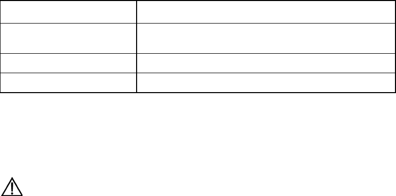
The following figure shows the relationship between IKE and IPSec.
TCP/UD
P
IPSec
IKEIKE
IPSec
TCP/UDP SA SA
SA negotiation
Encrypted IP message
IP
Router Router B
Figure SC-5-1 Diagram of relationship between IKE and IPSec
II. IKE features
z Avoid specifying manually all IPSec security parameters in password mapping of
both communication ends.
z Allow specifying the lifetime of IPSec SA
z Allow exchanging ciphering key during IPSec session
z Allow IPSec to provide anti-replay service
z Allow manageable and scalable IPSec to implement certificate authorization
support.
z Allow dynamic end-to-end authentication.

User Manual - Configuration Guide (Volume 3)
Versatile Routing Platform Chapter 5
Configuration of IKE
5-2
5.2 Configuring IKE
5.2.1 IKE Configuration Task List
IKE configuration task list is as follows:
z Create IKE security policy
z Select encryption algorithm
z Select authentication algorithm
z Configure pre-shared key
z Select hashing algorithm
z Select DH group ID
z Set IKE negotiation SA lifetime
5.2.2 Creating IKE Security Policy
I. Why these policies should be created?
IKE negotiation must be protected, so each IKE negotiation begins when each terminal
comes to the public (shared) IKE policy, which describes which security parameter to
use to protect subsequent IKE negotiation.
When two terminals come to a policy, the security parameters of this policy are
identified by SA established by each terminal, and these SAs apply to all subsequent
IKE communication during negotiation. Multiple policies with priority must be created
on each terminal so as to ensure that at least one policy can match that of the remote
terminal.
II. Parameters to be defined in policy
z Encryption algorithm: at present, it includes only 56-bit DES-CBC (DES-Cipher
Block Chaining)
z Hashing algorithm: SHA-1(HMAC anamorphosis) or MD5 (HMAC anamorphosis)
algorithm
z Authentication method: RSA signature or RSA real-time encryption
z Diffie-Hellman group ID
z SA lifetime
III. How to form matched policy
When IKE negotiation begins, IKE looks for a kind of IKE policy, which is consistent at
both terminals. The terminal that originates negotiation sends all its policies to the
remote terminal, and the latter will try to find a matched policy by comparing its policies
with highest priorities with those received from the former. When the policies from the
two terminals include the same encryption, hashing, authentication and Diffie-Hellman
parameters and when the specified lifetime of the policy from the remote terminal is
shorter than or equal to the compared policy lifetime, the matching selection is made (if
no lifetime is specified, the shorter one of the remote terminal policy will be used). If no
acceptable matched policy is found, IKE refuses to negotiate and will not establish
IPSec. If a matched policy is found, IKE will complete negotiation then create IPSec
security tunnel.
IV. Create IKE policy
The following should be clear before IKE configuration:

User Manual - Configuration Guide (Volume 3)
Versatile Routing Platform Chapter 5
Configuration of IKE
5-3
z Determine the intensity of authentication algorithm, encryption algorithm and
Diffie-Hellman algorithm (i.e., the calculation resources consumed and the security
capability provided). Different algorithms are of different intensities, and the higher
the algorithm intensity is, the more difficult it is to decode the protected data, but the
more the consumed resources are. The longer key usually has higher algorithm
intensity.
z Determine the security protection intensity needed in IKE exchange (including
hashing algorithm, encryption algorithm, ID authentication algorithm and DH
algorithm).
z Determine the authentication algorithm, encryption algorithm, hashing algorithm
and Diffie-Hellman group.
z Determine the pre-shared key of both parties.
1) Create IKE policy
The user can create multiple IKE policies, but must allocate a unique priority value for
each created policy. Both parties in negotiation must have at least one matched policy
for successfully negotiation, that is to say, a policy and the one in the remote terminal
must have the same encryption, hashing, authentication and Diffie-Hellman
parameters (the lifetime parameters may be a little different). If it is found there are
multiple matching policies after negotiation, the one with higher priority will be matched
first.
Please perform the following tasks in global configuration mode.
Table SC-5-1 Create IKE policy
Operation Command
Create IKE policy and enter IKE policy configuration mode crypto ike policy priority
Delete IKE policy no crypto ike policy priority
No IKE security policy is created by default.
5.2.3 Select Encryption Algorithm
There is only one encryption algorithm: 56-bit DES-Cipher Block Chaining (DES-CBC).
Before being encrypted, each plain text block will perform exclusive-OR operation with
an encryption block, thus the same plain text block will never map the same encryption
and the security is enhanced.
Please perform the following tasks in IKE policy configuration mode.
Table SC-5-2 Select encryption algorithm
Operation Command
Select encryption algorithm encryption des-cbc
Set the encryption algorithm to the default value no encryption
By default, DES-CBC encryption algorithm (i.e. parameter des-cbc) is adopted.
5.2.4 Select Authentication Algorithm
There is only one authentication algorithm: pre-share key
Please perform the following tasks in IKE policy configuration mode.

User Manual - Configuration Guide (Volume 3)
Versatile Routing Platform Chapter 5
Configuration of IKE
5-4
Table SC-5-3 Select authentication method
Operation Command
Select authentication method authentication pre-share
Restore the authentication method to the default value no authentication pre-share
By default, pre share key (i.e., pre-share) algorithm is adopted.
5.2.5 Set Pre-shared Key
If pre-shared key authentication method is selected, it is necessary to configure pre-
shared key.
Perform the following tasks in global configuration mode.
Table SC-5-4 Configure pre-shared key
Operation Command
Configure pre-shared key crypto ike key keystring address peer-address
Delete pre-shared key to restore its default value no crypto ike key keystring
By default, both ends of the security channel have no pre-shared keys.
5.2.6 Select Hashing Algorithm
Generally hashing algorithm uses HMAC framework to achieve its function. HMAC
algorithm adopts encryption hashing function to authenticate message, providing
frameworks to insert various hashing algorithm, such as SHA-1 and MD5.
There are two hashing algorithm options: SHA-1 and MD5. Both algorithms provide
data source authentication and integrity protection mechanism. MD5 has less digest
information, so it is usually considered to be slightly faster than SHA-1. A kind of attack
subject to MD5 is proved successful (but it is very difficult), but HMAC anamorphosis
used by IKE can stop such attacks.
Please perform the following tasks in IKE policy configuration mode.
Table SC-5-5 Select hashing algorithm
Operation Command
Select hashing algorithm hash { md5 | sha }
Set hashing algorithm to the default value no hash
By default SHA-1 hashing algorithm (i.e., parameter sha) is adopted.
5.2.7 Select DH Group ID
There are two DH (Diffie-Hellman) group ID options: 768-bit Diffie-Hellman group
(Group 1) or 1024-bit Diffie-Hellman group (Group 2). The 1024-bit Diffie-Hellman
group (Group 2) takes longer CPU time
Please perform the following tasks in IKE policy configuration mode.

User Manual - Configuration Guide (Volume 3)
Versatile Routing Platform Chapter 5
Configuration of IKE
5-5
Table SC-5-6 Select DH group ID
Operation Command
Select DH group ID group {1 | 2}
Restore the default value of DH group ID no group
By default, 768-bit Diffie-Hellman group (Group 1) is selected.
5.2.8 Set Lifetime of IKE Association SA
Lifetime means how long IKE exists before it becomes invalid. When IKE begins
negotiation, the first thing for it to do is to make its security parameters of the two
parties be consistent. SA quotes the consistent parameters at each terminal, and each
terminal keeps SA until its lifetime expires. Before SA becomes invalid, it can be
negotiated by the subsequent IKE to be reused. The new SA is negotiated before the
current SA becomes invalid.
The shorter the lifetime is (to a critical point), the more secure the IKE negotiation is.
But to save time for setting IPSec, the longer IKE SA lifetime should be configured.
If the policy lifetimes of two terminals are different, only when the lifetime of originating
terminal must be greater than or equal to that of the peer end can IKE policy can be
selected, and the shorter lifetime should be selected as IKE SA lifetime.
Perform the following tasks in IKE policy configuration mode.
Table SC-5-7 Set lifetime of IKE negotiation SA
Operation Command
Set lifetime of IKE SA lifetime seconds
Set lifetime as the default value no lifetime
By default, SA lifetime is 86400 seconds (a day). It is recommended that the configured
seconds should be greater than 10 minutes.
5.3 Monitoring and Maintenance of IKE
Please perform the monitoring and maintenance in privileged user mode.
Table SC-5-8 Monitoring and maintenance of IKE
Operation Command
Show IKE security association parameter show crypto ike sa
Show IKE security policy show crypto ike policy
Clear an SA clear crypto ike sa connection-id
1) Show IKE SA parameter
Quidway# show crypto ike sa
conn-id peer flags phase doi
1 202.38.0.2 RD|ST 1 IPSEC
2 202.38.0.2 RD|ST 2 IPSEC

User Manual - Configuration Guide (Volume 3)
Versatile Routing Platform Chapter 5
Configuration of IKE
5-6
Flag meaning:
RD--Ready ST--Stayalive RT--Replaced FD--Fading
Execute the following command to clear security association 1.
Quidway# clear crypto ike sa 1
Then the SA will show the following information:
Quidway# show crypto ike sa
conn-id peer flags phase doi
2 202.38.0.2 RD|ST 2 IPSEC
Flag meaning:
RD--Ready ST--Stayalive RT--Replaced FD--Fading
Table SC-5-9 Description about the command field show crypto ike sa
Operation Command
Security channel ID conn-id
Peer IP address of this SA peer
Show the status of this SA
NONE means this SA is being established
READY means this SA has been established successfully
STAYALIVE means that lifetime is negotiated, and this SA will be refreshed
in fixed interval.
REPLACED means that a timeout has happened
FADING means this SA has been replaced, and will be cleared
automatically after some time
Flags
Phase of SA phase
Explanation domain of SA doi
2) Show IKE security policy
Quidway# show crypto ike policy
Protection suite priority 15
encryption algorithm: DES - CBC
hash algorithm: MD5
authentication method: Pre-Shared Key
Diffie-Hellman Group: MODP1024
Lifetime: 5000 seconds, no volume limit
Protection suite priority 20
encryption algorithm: DES - CBC
hash algorithm: SHA
authentication method: Pre-Shared Key
Diffie-Hellman Group: MODP768
lifetime: 10000 seconds, no volume limit
Default protection suite
encryption algorithm: DES - CBC
hash algorithm: SHA
authentication method: Pre-Shared Key
Diffie-Hellman Group: MODP768
Lifetime: 86400 seconds, no volume limit
The information shows the protection priority, encryption algorithm, hashing algorithm,
authentication algorithm, Diffie-Hellman group and IKE SA lifetime.
5.4 Typical Configuration of IKE
I. Networking requirements
z Hosts A and B communicates securely, and a security channel is established with
IKE automatic negotiation between security gateways A and B.
User Manual - Configuration Guide (Volume 3)
Versatile Routing Platform Chapter 5
Configuration of IKE
5-7
z Configure an IKE policy on Gateway A, with Policy 10 is of highest priority and the
default IKE policy is of the lowest priority.
z Pre-shared key authentication algorithm is adopted.
II. Networking diagram
Host BHost A
Security Gateway B
Internet
Security Gateway A
Serial 0
202.38.160.1 Serial 0
171.69.224.33
Figure SC-5-2 Networking diagram of IKE configuration example
III. Configuration procedure
Configuration on Security Gateway A.
! Configure a IKE Policy 10
Quidway (config)# crypto ike policy 10
! Specify the hashing algorithm used by IKE policy as MD5
Quidway (config-crypto-ike-policy-10)# hash md5
! Use pre-shared key authentication method
Quidway (config-crypto-ike-policy-10)# authentication pre-share
! Configure “abcde” for peer 171.69.224.33
Quidway (config)# crypto ike key abcde address 171.69.224.33
! Configure IKE SA lifetime to 5000 seconds
Quidway (config-crypto-ike-policy-10)# lifetime 5000
Configuration on Security Gateway B.
! Use default IKE policy on Gateway B and configure the peer authentication word.
Quidway (config)# crypto ike key abcde address 202.38.160.1
The above are IKE negotiation configurations. To establish IPSec security channel for
secure communication, it is necessary to configure IPSec correspondingly. For detailed
contents, please refer to the configuration samples in the chapter IPSec Configuration.
5.5 IKE Fault Diagnosis and Troubleshooting
When configuring parameters to establish IPSec security channel, you can use the
debug ike error command to enable the Error debugging of IKE to help us find
configuration problems. The command is as follows:

User Manual - Configuration Guide (Volume 3)
Versatile Routing Platform Chapter 5
Configuration of IKE
5-8
Problem 1: Invalid user ID information
Troubleshooting: please follow the steps below.
User ID information is the data for the user originating IPSec communication to identify
itself. In practical applications we can use user ID to establish different security path for
protecting different data streams. At present we use the user IP address to identify the
user.
got NOTIFY of type INVALID_ID_INFORMATION
or
drop message from A.B.C.D due to notification type INVALID_ID_INFORMATION
Check whether ACL contents in cryptomap configured at interfaces of both ends are
compatible. It is recommended for the user to configure ACL of both ends to mirror
each other.
Problem 2: Unmatched policy
Troubleshooting: please follow the steps below.
Enable the debug ike error command, you can see the debugging information.
got NOTIFY of type NO_PROPOSAL_CHOSEN
or
drop message from A.B.C.D due to notification type NO_PROPOSAL_CHOSEN
Both parties of negotiation have no matched policy. Check the protocol used by
cryptomap configured on interfaces of both parties to see whether the encryption
algorithm and authentication algorithm are the same.
Problem 3: Unable to establish security channel
Troubleshooting: please follow the steps below.
Check whether the network is stable and the security channel is established correctly.
Sometimes there is a security channel but there is no way to communicate, and ACL of
both parties are checked to be configured correctly, and there is also matched policy. In
this case, the problem is usually cased by the restart of one router after the security
channel is established.
Solution:
1) Use the command show crypto ike sa to check whether both parties have
established SA of Phase 1.
2) Use the command show crypto ipsec sa map to check whether the cryptomap
on interface has established IPSec SA.
3) If the above two results show that one party has SA but the other does not, then
use the command clear crypto ike sa to clear SA with error and re-originate
negotiation.
HUAWEI®
VRP
User Manual – Configuration Guide
Volume 3
07 – VPN Configuration (VPN)

User Manual - Configuration Guide (Volume 3)
Versatile Routing Platform Table of Contents
i
Table of Contents
Chapter 1 Overview of VPN ......................................................................................................... 1-1
1.1 VPN features..................................................................................................................... 1-1
1.2 Classification of IP VPN.................................................................................................... 1-2
Chapter 2 Configuration of L2TP ................................................................................................2-1
2.1 Brief Introduction to L2TP Protocol................................................................................... 2-1
2.1.1 Overview of VPDN ................................................................................................. 2-1
2.1.2 L2TP Protocol......................................................................................................... 2-2
2.2 Configuring L2TP .............................................................................................................. 2-6
2.2.1 L2TP Configuration Task List................................................................................. 2-6
2.2.2 Configuring at LAC Side......................................................................................... 2-6
2.2.3 Configuring at LNS Side......................................................................................... 2-8
2.2.4 Optional configuration .......................................................................................... 2-10
2.3 Monitoring and Maintenance of L2TP ........................................................................ 2-13
2.4 Typical Configuration of L2TP ........................................................................................ 2-14
2.4.1 NAS-Initialized VPN ............................................................................................. 2-14
2.4.2 Client-Initialized VPN ........................................................................................... 2-16
2.4.3 Single User Interconnects Headquarters via Router............................................ 2-17
2.5 Fault Diagnosis of L2TP ................................................................................................. 2-19
Chapter 3 Configuration of GRE .................................................................................................3-1
3.1 Brief Introduction to GRE Protocol.................................................................................... 3-1
3.2 Configuring GRE............................................................................................................... 3-3
3.2.1 GRE Configuration Task List.................................................................................. 3-3
3.2.2 Creating Virtual Tunnel Interface ........................................................................... 3-4
3.2.3 Setting the Source Address of Tunnel Interface .................................................... 3-4
3.2.4 Setting the Destination Address of Tunnel Interface ............................................. 3-4
3.2.5 Setting the Network Address of Tunnel Interface .................................................. 3-5
3.2.6 Setting the Encapsulation Mode of Tunnel Interface Message ............................. 3-5
3.2.7 Setting the Identification Key Word of Tunnel Interface......................................... 3-5
3.2.8 Setting Tunnel Interface to Check with Check Sum .............................................. 3-5
3.2.9 Setting Tunnel Interface to Synchronize Datagram Serial Number ....................... 3-6
3.3 Monitoring and Maintenance of GRE ........................................................................... 3-6
3.4 Typical Configuration of GRE ........................................................................................... 3-7
3.5 Troubleshooting GRE ....................................................................................................... 3-9

User Manual - Configuration Guide (Volume 3)
Versatile Routing Platform Chapter 1
VPN Overview
1-1
Chapter 1 VPN Overview
Virtual Private Network, VPN for short, is one of the rapidly developing technologies
along with the development of Internet in recent years. In the wake of enterprise
expansion, widely located clients and increasing partners, modern enterprises make
more and more use of Internet resources to conduct such activities as promotion,
marketing, after-sale service, training and cooperation. Many enterprises tend to
replace their private data network with Internet. Like the current private networks of
enterprises, VPN established on the public network is safe, reliable and manageable.
This kind of logic network, which uses Internet to transmit private information, is called
VPN.
1.1 VPN features
VPN features the following:
1) Different from conventional networks, VPN does not actually exist; it is a virtual
network formed by resource configuration of the existing network .So the carriers
can make use of their spare network resources to provide VPN service and profit
from the network resources to the maximum extent.
2) VPN is specially used for specific enterprises or user groups. It makes no
difference to VPN users in using VPN and conventional private networks.
However, VPN is actually established on the public network or on the networks of
other carriers. In order to meet the requirements of private networks, some
technical means must be adopted to ensure the resource independence between
VPN and the public network or its bearing network. That is, the resources of a VPN
are not usually allowed to be used by other VPNs on the bearing network or
network members not belonging to the VPN. Another point is that VPN should be
safe enough, that is, the information from VPN users should not go out of VPN and
the external users can not generally access the information in VPN. The above
mentioned two problems are the main problems to be solved in VPN protocol.
3) VPN is not a simple higher-level service. Network interconnection between the
users of private networks is required for VPN service, including creation of VPN
internal network topology, route calculation, access and exit of members. So VPN
technology is much more complicated compared with the mechanism of various
ordinary point-to-point applications.
VPN has the following advantages:
1) With VPN, reliable and safe connection can be established between remote users,
branches of companies and commercial partners, and between suppliers and
companies. And security of data output can be ensured. The advantage is
especially significant in the integration of E-commerce or financial network with the
communication network.
2) With VPN, IP network of lower cost can be used to transmit data stream so as to
downsize the cost to establish Intranet and to make effective use of the currently
idle network resources.
3) VPN users can be added and deleted with only relative configurations and without
changing hardware, making VPN applications highly flexible.
4) With VPN, a great amount of maintenance personnel of private network of the
enterprises can engage in more important services, leaving the VPN management
and maintenance of ISP or other network companies.
User Manual - Configuration Guide (Volume 3)
Versatile Routing Platform Chapter 1
VPN Overview
1-2
5) With VPN, users can make mobile access at any time and place, meeting the
increasing mobile service requirements.
6) VPN with service quality guarantee, e.g. MPLS VPN, can provide different levels
of service quality guarantees for users in exchange for different service charges,
harvesting surplus profit. In addition, in terms of implementing the same functions,
the networks can be used more effectively when these services are provided by
specialized public networks rather than the networks established by the
enterprises themselves.
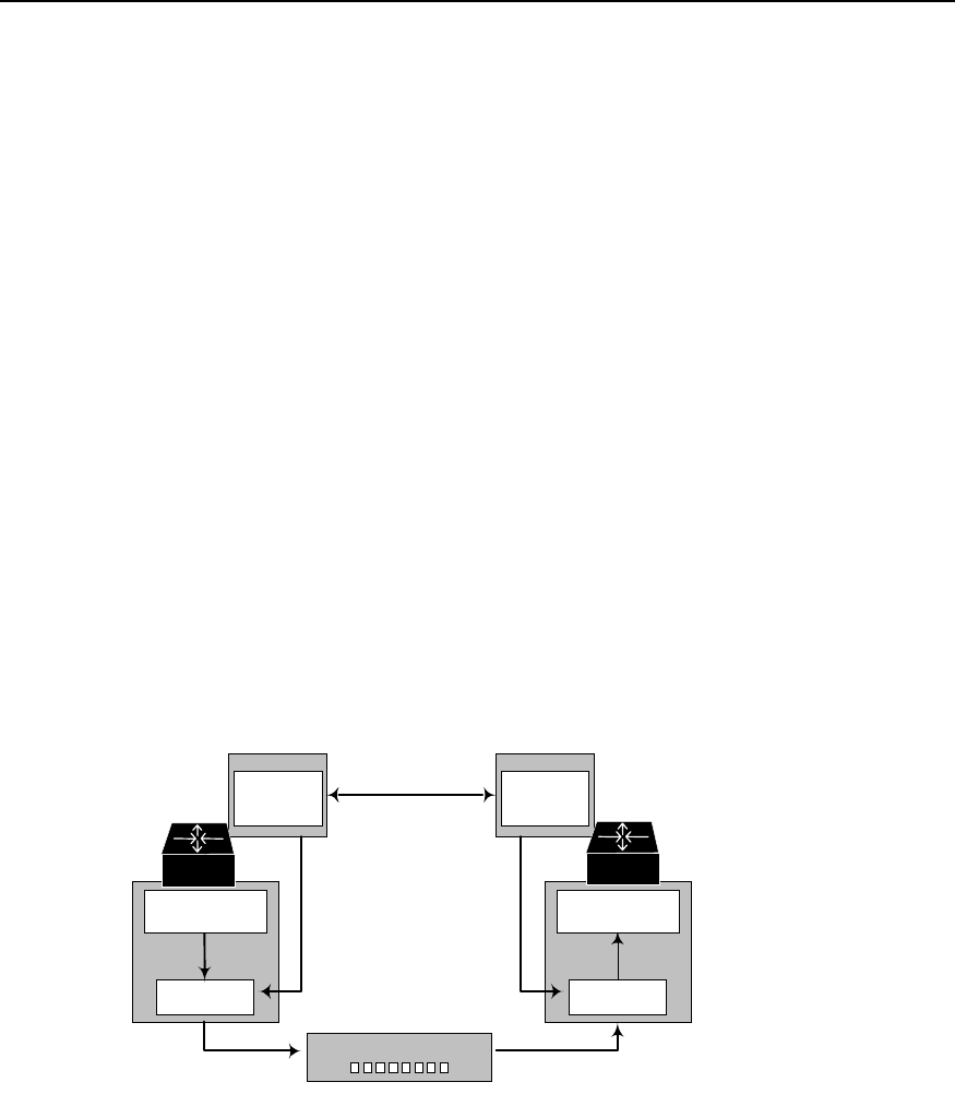
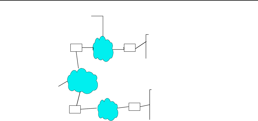
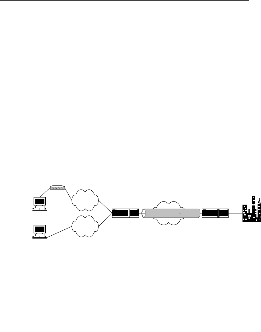
Take an enterprise for example. The Intranet established with VPN is shown in the
following figure.
POP
POP
POP
PC PSTN / ISDN
Partner
Remote users
Internal server
Internet
Headquarter
Figure VPN-1-1 Schematic diagram of VPN networking
It can be found in the above figure that the users of internal resources of enterprises
access the POP (Point of Presence) server of local ISP via PSTN network, and thus
they can communicate with each other. Conventional WAN construction technique can
only score the same goal with the aid of leased line between them. After VPN is
established, the remote users and the clients in other places can access internal
resources of enterprises even if they do not have the Internet access authority of local
ISP. This means a lot to clerks who travel a lot and geographically widely distributed
clients.
VPN services of enterprises only require a server supporting VPN at resource sharing
location (a Windows NT server or a router supporting VPN). After accessing local POP
server via PSTN, resource users directly call the remoter servers of enterprises (VPN
servers). The call mode is the same as that with PSTN connection, with the rest of work
completed by Access Server of ISP.
1.2 Classification of IP VPN
IP VPN means the simulation of leased line services of private WAN equipment
performed with IP facilities (including public Internet or private IP backbone network).
IP VPN has the following classification methods:
I. According to operation mode
1) CPE-based VPN
The users not only install expensive equipment and private authentication tools, but
also are engaged in multifarious VPN maintenance (e.g. channel maintenance and
bandwidth management). The networking is complicated, but its service scalability is
weak.
2) Network-based VPN NBIP-VPN

User Manual - Configuration Guide (Volume 3)
Versatile Routing Platform Chapter 1
VPN Overview
1-3
The maintenance function of VPN is allocated to be completed by to ISP (the users are
allowed to manage and control services to some extent) and VPN functions are mainly
fulfilled on the equipment at network side. This practice reduces the investments of the
users, increases the flexibility and scalability of services and brings new incomes to the
operators.
II. According to the layer where the tunnel is
1) Layer 2 tunneling protocol
Layer 2 tunneling protocol starts from NAS (Network Access Server) and ends on the
equipment at user side. All the PPP frames are encapsulated in the tunnel. The current
layer 2 tunneling protocol mainly includes Point-to-Point Tunneling Protocol (PPTP)
(supported by Microsoft, Ascend and 3COM, and also in Windows NT 4.0 above),
Layer 2 Forwarding Protocol (L2F) (supported by Cisco and Nortel), and Layer 2
Tunneling Protocol (L2TP) (drafted by IETF and aided by Microsoft, integrating the
advantages of the above two protocols, and thus accepted by the industry as standard
RFC). L2TP can be used for not only dial-up VPN services but also VPN services of
leased line.
2) Layer 3 tunneling protocol
Layer 3 tunneling protocol starts from and ends in ISP. PPP session ends in NAS and
only layer 3 messages are carried in the tunnel. The current layer 3 tunneling protocol
mainly includes General Route Encapsulation Protocol (GRE) and IPSec. GRE and
IPSec are mainly used for VPN services of leased line.
Comparing with layer 2 tunnel, layer 3 tunnel is safe, scalable and reliable. In terms of
security, as layer 2 tunnel usually ends on the equipment at user side, there exist great
challenges for the security and firewall technical of user’s network. But layer 3 tunnel
usually ends on ISP gateway and does not impose any threat to the security of user’s
network.
In terms of scalability, all the PPP frames are encapsulated in layer 2 IP tunnel and
transmission efficiency may be degraded. And PPP session will be run through entire
tunnel and end on nodes or servers of user’s network. So the gateway at user side
must save a great deal of the status and information of PPP session, which will add to
system load and affect scalability considerably. In addition, as LCP and NCP
negotiations of PPP are very sensitive for time, the efficiency of IP tunnel will result in
such a series of problems as PPP session timeout. As layer 3 tunnel ends in ISP
gateway and PPP session ends in NAS, it is unnecessary for the gateway at user side
to manage and maintain the status of respective PPP session, thus minimizing the
system load.
Generally, layer 2 and 3 tunneling protocols are independently used, however,
reasonable combination of the two layers of protocols will provide better security for the
users (e.g. use L2TP together with IPSec protocol).
III. According to service purpose
1) Intranet VPN
In Intranet VPN, respective locations of enterprises are interconnected through public
network, which is the extension or alternative of traditional leased line networks or other
enterprise networks.
2) Access VPN
Access VPN has two structures: Client-initiated VPN connection and NAS-initiated
VPN connection.
3) Extranet VPN

User Manual - Configuration Guide (Volume 3)
Versatile Routing Platform Chapter 1
VPN Overview
1-4
Extranet VPN means that the VPN extends Intranet to partners and clients through
VPN, so that different enterprises can build their VPNs through public networks.
IV. According to networking model
1) Virtual Leased Line (VLL)
VLL simulates the conventional leased line service, i.e., simulating the leased line with
IP network and providing asymmetrical and inexpensive “DDN” service. For the users
at both ends of VLL, the VLL is equivalent to the previous leased line.
2) Virtual Private Dial-up Network (VPDN)
In VPDN, VPN is implemented with dial-up and access services (ISDN PSTN) of public
network, which provides access service for enterprises, mini ISPs and mobile offices.
3) Virtual Private LAN Segment (VPLS) service
In VPLS, LANs can interconnect through virtual private network segment, which is the
extension of LAN across IP public network.
4) Virtual Private Route Network (VPRN) service
There are two types: one is the VPRN, using with such conventional VPN protocols as
IPSec and GRE, and the other is VPN in MPLS mode.

User Manual - Configuration Guide (Volume 3)
Versatile Routing Platform Chapter 2
Configuration of L2TP
2-1
Chapter 2 Configuration of L2TP
2.1 Brief Introduction to L2TP Protocol
2.1.1 Overview of VPDN
I. Brief induction to VPDN
In VPDN, VPN is fulfilled with dial-up and access services (ISDN PSTN) of public
network, which provides access service for enterprises, mini ISP and mobile offices. As
telecom carriers and large ISPs have a lot of access equipment, facilities and
management experiences, other enterprises can make full use of their existing
equipment and facilities instead their own investment on access equipment, so that
their services can be more specialized and systematic.
VPDN adopts private network encryption and communication protocol, so enterprises
can establish safe VPN on public networks. Enterprise personnel on business leave
can connect with enterprise's remote internal network via virtual encryption channel,
while other users on public networks can not access the Intranet resources via such
virtual channel.
VPDN is often used by the following users:
z Those users whose branches are geographically distributed, with many mobile
personnel, e.g. enterprise users and tele-education users.
z Those users whose are geographically distributed have to rely on toll calls or even
international toll calls.
z Those who have specific requirements for line security and availability.
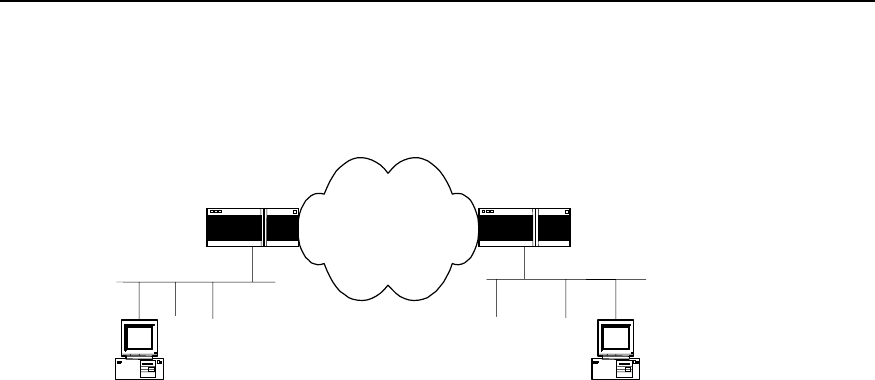
II. Operation principle of VPDN
The networking diagram of typical VPDN application is shown in the following figure.
PC
PSTN/ISDN
Remote users
NAS
Remote users
Internal server
Internet backbone network
L2TP
NAS LNS
Figure VPN-2-1 Networking diagram of typical VPDN application
VDPN is composed of NAS, equipment at user side and management tool.

User Manual - Configuration Guide (Volume 3)
Versatile Routing Platform Chapter 2
Configuration of L2TP
2-2
1) NAS is provided by telecom departments or large ISPs. As the access server of
VPDN, NAS provides WAN interfaces, is in charge of connecting PSTN or ISDN,
and supports various LAN protocols, security management and authentication,
and supports tunnels and relative techniques.
2) The user-side equipment is located in the headquarters of the user. According to
different network functions, it may be the equipment, which provide such functions
as NAS, router or firewall. LNS in the figure stands for L2TP Network Server.
3) The management tool manages VPDN equipment and users, including NMS,
authentication, authorization and accounting (AAA).
Remote dial-up users dial up and access local ISP NAS via local PSTN or ISDN. With
local ISP connection and proper tunneling protocol encapsulating higher-level protocol,
a VPN is established between NAS and the gateway of opposite end.
III. Method to realize VPDN
There are two modes to realize VPDN:
1) One mode is that NAS and VDPN gateway establish the channel with tunneling
protocol. Directly connect PPP of clients to the gateways of enterprises. The
current available protocols are L2F and L2TP.The advantage of the mode is its
transparency to users. With one login, the users can access Intranet, which
authenticates the users and distributes the addresses without occupying public
addresses. The platform to access such network is not limited. In the mode, NAS
should support VPDN protocol and the authentication system should support
VPDN attributes. The gateway is usually router or VPN private gateway.
2) The other mode is that the client and VPDN gateway establish the tunnel. The
client first connects Internet, then establishes channel connection with the
gateway through private client software (such as L2TP supported by Win2000).
The advantage of the mode is that there is no mode and geographical limits for
Internet access of users, depending on no ISP. The setback is that the users need
to install special software (usually Windows2000 platform), instead of other
platforms familiar with the users.
VPDN tunneling protocol includes PPTP, L2F and L2TP. The most popular one is L2TP
at present.
2.1.2 L2TP Protocol
L2TP (Layer 2 Tunneling Protocol) supports the tunneling transmission of the packets
on PPP link layer. Integrating the respective advantages of L2F protocol of Cisco and
PPTP protocol of Microsoft, it becomes the industrial standard of layer 2 tunneling
protocol of IETF.
I. Tunnel and session
L2TP is a connection-based protocol.L2TP tunnel is established between LAC (L2TP
Access Concentrator) and LNS (L2TP Network Server), which is composed of one
control connection and n (n≧0) sessions. Only one L2TP tunnel can be established
between a pair of LAC and LNS. Both control message and PPP data message are
transmitted in the tunnel. The session is also established between LAC and LNS. But
its establishment must follow the successful establishment of tunnel (including the
exchange of such information as identity protection, L2TP version, frame type and
hardware transmission type). One session connection corresponds to one PPP data
stream between LAC and LNS.

User Manual - Configuration Guide (Volume 3)
Versatile Routing Platform Chapter 2
Configuration of L2TP
2-3
L2TP header includes the information of Tunnel ID and Session ID, which are used to
identify different tunnels and sessions. The messages with the same Tunnel ID and
different Session ID will be multiplexed in one tunnel. Tunnel ID and Session ID are
distributed by opposite end.
L2TP uses HELLO message to detect the connectivity of a tunnel. When the tunnel is
idle for some time, LAC and/or LNS begin to transmit HELLO message to opposite end.
If not receiving a reply to HELLO message for some time, the tunnel will be cleared up.
II. Control message and data message
L2TP has two types of messages: control message and data message. The control
message is used to establish, maintain and transmit the tunnel and session connection.
And the data message is used to encapsulate PPP frame and transmit in the tunnel.
The transmission of control message is reliable, while that of data message is not. If
data message is lost, it will not be transmitted again. L2TP supports flow control and
congestion control of control message instead of those of data message.
L2TP is transmitted in the form of UDP message. L2TP registers UDP1701 port, which
is only used for initial tunnel establishment. Originating side of L2TP tunnel randomly
selects an idle port (it is unnecessarily 1701) and transmits a message to 1701 port of
receiving side. After receiving the message, the receiving side randomly selects an idle
port (it is unnecessarily 1701 and transmits a message back to the specified port of the
originating side. By now, the selected ports of both sides are selected and remain
unchanged during the time segment when the tunnel is connected.
After being transmitted to L2TP and added with L2TP header, PPP frame is
encapsulated into UDP message and transmitted on TCP/IP network.
III. Two typical L2TP tunnel modes
z Originated by remote dial-up users. Remote system accesses LAC via
PSTN/ISDN, then LAC originates the request of establishing channel connection
to LNS via Internet. Dial-up user addresses are distributed by LNS. The
authentication and charging of remote dial-up users can be completed by the
agent at LAC side or completed at LNS side.
z Directly originated by LAC clients (the users who locally support L2TP protocol).
Here, LAC clients directly originate the request of channel connection to LNS
without separate LAC equipment. Here, the distribution of LAC client addresses
and AAA authentication are completed by LNS.
User Manual - Configuration Guide (Volume 3)
Versatile Routing Platform Chapter 2
Configuration of L2TP
2-4
LAC LNS
LAC LNS
LAC client
Remote client
Home LAN
PSTN/ISDN
Internet
Internet
Home LAN
Figure VPN-2-2 Two typical L2TP tunnel modes
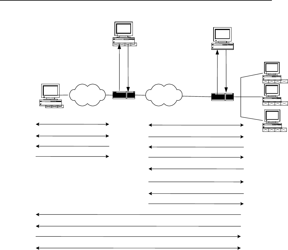
IV. Call setup flow of L2TP tunnel
Call setup flow of L2TP channel is shown in the following:
User Manual - Configuration Guide (Volume 3)
Versatile Routing Platform Chapter 2
Configuration of L2TP
2-5
LAC LNS
WAN
PSTN/ISDN
LAC RADIUS server LNS RADIUS server
(5)Request tunnel message
user = domain
password = quidway
(6)AV PairsTunnel message
Local name(LAC)
Tunnel password
Tunnel type
LNS IP Address
Access request
(15)(20)
Access response
(16)(21)
(15)
(20)
(16)
(21)
Call setup (1)
PPP LCPSetup (2)
user CHAP challenge(3)
user CHAP response(4)
Tunnel establishment(7)
Tunnel authentication CHAP challenge(8)
LNS CHAP response(9)
Authentication Passes (10)
CHAP challenge(11)
LAC CHAP response(12)
Authentication passes (13)
user CHAP response + response identifier + PPP consultation parameter (14)
Pass (17)
Optional second time CHAP challenge(18)
CHAP response(19)
Authentication passes (22)
Figure VPN-2-3 Call setup flow of L2TP channel
V. Features of L2TP protocol
z Flexible identity authentication mechanism and high security
L2TP protocol does not provide connection security, but it can depend on the
authentication (e.g. CHAP and PAP) provided by PPP, so it has all security features of
PPP. L2TP can integrate with IPsec to fulfill data security, so it is difficult to attack the
data transmitted with L2TP. As required by specific network security, L2TP adopts
channel encryption technique, end-to-end data encryption or application layer data
encryption on it to improve data security.
z Multi-protocol transmission
L2TP transmits PPP packet. Thus multi-protocol can be encapsulated in PPP packet.
z Support the authentication of RADIUS server
LAC requires the authentication of RADIUS with user name and password. RADIUS
server is in charging of receiving authentication request of the user, fulfilling the
authentication and returning to LAC the configuration information for connection
establishment.
z Support internal address distribution

User Manual - Configuration Guide (Volume 3)
Versatile Routing Platform Chapter 2
Configuration of L2TP
2-6
LNS can be put behind Intranet firewall. It can dynamically distribute and manage the
addresses of remote users and support the application of private addresses
(RFC1918). The distributed addresses for remote users are private addresses in
enterprise instead of Internet addresses, thus the addresses can be easily managed
and the security can also be improved.
z Flexible network charging
Charge in both LAC and LNS at the same time, that is, in ISP (to generate bills) and
Intranet gateway (to pay for charge and audit). L2TP can provide such charging data as
transmitted packet number, byte number, start time and end time of the connection.
And it can easily perform network charging according to these data.
z Reliability
L2TP supports backup LNS. When an active LNS is inaccessible, LAC (access server)
can reconnect the backup LNS to improve the reliability and fault tolerance of VPN
service.
2.2 Configuring L2TP
2.2.1 L2TP Configuration Task List
L2TP configuration task can be divided into the configurations at LAC and LNS sides.
I. Configuration at LAC side
z Start/Disable VPDN.
z Create VPDN group.
z Set to originate L2TP connection request and LNS addresses.
z Set user name and password.
II. Configuration at LNS side
z Start/Disable VPDN.
z Create VPDN group.
z Create or delete virtual interface template.
z Set the name of receiving channel opposite end.
III. Optional configuration
z Set local name.
z Set channel authentication and password.
z Force local end to perform CHAP authentication.
z Force LCP to re-negotiation.
z Set domain name delimiter and search sequence.
z Force to disconnect channel.
2.2.2 Configuring at LAC Side
I. Enable/disable VPDN
Perform the following task in global configuration mode.

User Manual - Configuration Guide (Volume 3)
Versatile Routing Platform Chapter 2
Configuration of L2TP
2-7
Table VPN-2-1 Enable/disable VPDN
Operation Command
Enable VPDN to run. vpdn enable
Disable VPDN to run. no vpdn enable
Disable VPDN to run by default.
II. Create VPDN group
The information of dial-up users will be loaded on specific VPDN group, so LAC and
LNS can establish L2TP tunnel only on specific VPDN group.
Perform the following task in global configuration mode.
Table VPN-2-2 Create VPDN group
Operation Command
Create VPDN group and enter the configuration mode of VDPN group. vpdn-group group-number
Delete the existing VPDN group. no vpdn-group group-number
Do not create VPDN by default. group-number is an integer, ranging 1 to 3000.
III. Set user name and password and configure user authentication
LAC will authenticate remote dial-in user name and password to check whether he is a
VPN user. Only after the authentication, can the request of establishing channel
connection be generated, or the user will be turn to services of other types.
As the authentication and charging at LAC side are performed via RADIUS server, the
authentication function of RADIUS server on PPP users will be started.
Table VPN-2-3 Set user name and password and configure user authentication
Operation Command
Set user name and password. user username password { 0 | 7 } password
Cancel the set user name and password. no user username
Configure to authenticate users. ppp authentication { pap | chap }
Cancel the operation to authenticate users. no ppp authentication { pap | chap }
Enable AAA. aaa-enable
Authentication method table of PPP user configuration. aaa authentication ppp { default | list-name }
{ method1} [ method2 ... ]
As L2TP is not the standard attribute of RADIUS protocol, it is necessary to add the
definition of L2TP attribute table to RADIUS server attribute domain.

User Manual - Configuration Guide (Volume 3)
Versatile Routing Platform Chapter 2
Configuration of L2TP
2-8
Table VPN-2-4 L2TP attribute table
Attribute value Name Meaning
100 Tunnel-Type Tunnel type (L2TP=1).
101 L2TP-Tunnel-Password L2TP tunnel password.
102 Local-Name Local name of the channel.
103 LNS-IP-Address IP address of LNS.
104 Tunnel-Medium-Type Medium type of the tunnel (IP=1).
105 Vpdn Group Number VPDN group number.
IV. Set the connection request to originate L2TP channel.
After dial-in users pass the authentication of VPN users, LAC is in charge of originating
the channel establishment request to LNS and set the corresponding IP addresses of
LNS side.
In addition to specifying IP addresses of LNS side, LAC side provides three user
authentication modes: according to “user-name”, the specific “domain-name” and the
“dialed-number”.
At most five LNS IP addresses can be set, which can be searched according to the
sequence of the configured IP addresses of users.
Perform the following task in the configuration mode of VPDN group.
Table VPN-2-5 Set connection request to originate L2TP channel
Operation Command
Configure the connection request to originate the
channel. request dialin l2tp ip ip-address [ ip ip-address ... ]
{ domain domain-name | fullusername user-name }
Cancel the connection request to originate the channel. no request dialin l2tp [ ip ip-address ]
By default, the channel connection request is originated according to the full “user-
name”.
2.2.3 Configuring at LNS Side
I. Enable/disable VPDN
Perform the following task in global configuration mode.
Table VPN-2-6 Enable/disable VPDN
Operation Command
Enable VPDN to run. vpdn enable
Disable VPDN to run. no vpdn enable
Disable VPDN running by default.

User Manual - Configuration Guide (Volume 3)
Versatile Routing Platform Chapter 2
Configuration of L2TP
2-9
II. Create VPDN group
LAC and LNS can establish L2TP tunnel only on specific VPDN group.
Perform the following task in global configuration mode.
Table VPN-2-7 Create VPDN group
Operation Command
Create VPDN group. vpdn group group-number
Delete VPDN group. no vpdn group group-number
No VPDN group is created by default. The value of “group-number” may be an integer
between 1 and 3000.
III. Create/delete virtual interface template
Virtual template is mainly used to configure operational parameters of dynamically
creating virtual interface in router operation.
Perform the following task in global configuration mode.
Table VPN2-8 Create/delete virtual interface template
Operation Command
Create virtual interface template. interface virtual-template virtual-template-number
Delete virtual interface template. no interface virtual-template virtual-template-number
By default, the value of virtual-template-number” is 1, which may be an integer between
1 and 25.
After creating virtual template, designate IP address of virtual template and
encapsulate PPP protocol, then the virtual template can work. The users can select to
configure authentication on virtual template interface as required.
IV. Set receiving the connection request to originate L2TP channel
After receiving the channel establishment request originated at LAC side, channel
establishment depends on LAC name.
Perform the following task in the configuration mode of VPDN group.
Table VPN-2-9 Set to receive the connection request to originate L2TP channel
Operation Command
Set to receive the connection request to originate L2TP
channel. accept dialin l2tp virtual-template virtual-
template-number [remote remote-name ]
Delete the connection request to originate L2TP channel. no accept dialin
When VPDN group 1 is used, it is not necessary to specify channel opposite end name
“remote-name”. If the opposite end name is designated in the configuration mode of
VPDN group 1, VPDN 1 will not be the default VPDN group.

User Manual - Configuration Guide (Volume 3)
Versatile Routing Platform Chapter 2
Configuration of L2TP
2-10
2.2.4 Optional configuration
I. Set local name of channel
After a channel is established, the users can respectively configure the local channel
name at LAC side and LNS side.
Perform the following task in the configuration mode of VPDN group.
Table VPN-2-10 Set local name of channel
Operation Command
Set local channel name. local name name
Delete local channel name. no local name name
By default, the host name “hostname” of the router acts as the local channel name.
II. Start channel authentication and set authentication password
Before creating a channel connection, the users can decide as required whether to
start channel authentication.
There are the following three channel authentication modes:
z LAC authenticates LNS.
z LNS authenticates LAC.
z LAC and LNS authenticate each other.
It can be found that LAC or LNS can originate channel authentication request. However,
if one side starts the channel authentication, the channel can be established only when
the passwords on both ends of the channel are totally the same. If channel
authentication is disabled on both ends of the channel, whether the channel
authentication passwords are the same will be meaningless.
In order to ensure channel security, users are recommended not to disable channel
authentication.
Perform the following task in the configuration mode of VPDN group.
VPN-2-11 Start channel authentication and set authentication password
Operation Command
Start channel authentication l2tp tunnel authentication
Disable channel authentication. no l2tp tunnel authentication
Set the password of channel authentication. l2tp tunnel password { 0 | 7 } password
Cancel the password of channel authentication. no l2tp tunnel password
Start channel authentication by default. If no channel authentication password is
configured, the “hostname” of the router will act as channel authentication password.
III. Force local end to perform CHAP authentication
In some cases (e.g. consider the security at LNS side), after LAC performs agent
authentication on the users, LNS can authenticate the users again. Here, the users will
be authenticated twice. The first authentication is at LAC side and the second one at

User Manual - Configuration Guide (Volume 3)
Versatile Routing Platform Chapter 2
Configuration of L2TP
2-11
LNS side. Only after passing the two authentications can the channel be established.
Only when configured at LNS side will it be valid to force local end to perform CHAP
authentication.
If CHAP authentication is forced to perform at LNS side, user name, password and user
authentication need to be set in advance at LNS side and AAA must be started, before
local end can be forced to perform CHAP authentication.
Perform the following task in the configuration mode of VPDN group.
Table VPN-2-12 Force local end to perform CHAP authentication
Operation Command
Force local end to perform CHAP authentication. force-local-chap
Cancel the operation that local end performs CHAP authentication. no force-local-chap
Local end does not perform CHAP authentication by default.
IV. LNS forces LCP to renegotiate
For NAS-Initialized VPN service request, at the beginning of PPP session, the users
first perform PPP negotiation with NAS. If negotiation succeeds, NAS initiated channel
will be connected and the user information will be transmitted to LNS that decides the
legality based on the received agent authentication information.
But in some specific cases (e.g. when it is necessary to authenticate and charge at
LNS), the command “lcp renegotiation” can be used to force LNS to perform LCP
negotiation with users again, neglecting agent authentication information at NAS side.
Only when configured at LNS side, can it be valid to force LCP to renegotiate.
Perform the following task in the configuration mode of VPDN group.
Table VPN-2-13 Force LCP to renegotiate
Operation Command
Force LCP to renegotiate. lcp renegotiation
Disable LCP to renegotiate. no lcp renegotiation
LCP does not renegotiate by default.
V. Set domain name delimiter and search sequence
In the case of a lot of L2TP access users, it will waste time to search users in sequence.
Here, set the necessary search tactics (e.g. prefix and suffix delimiters) to speed up the
search.
The delimiter includes prefix delimiter and suffix delimiter. The delimiter includes four
special characters: @, # , & and /. The example of the user with prefix delimiter is
“huawei.com# vpdnuser” and the example of the user with suffix delimiter is
“vpdnuser@huawei.com”. In the search, separate user name from prefix/suffix
delimiter. The search based on defined rules will greatly speed up search sequence.
After setting prefix/suffix delimiter, four search orders are optional:
z “dnisdomain” (First search according to called number, then according to domain
name)

User Manual - Configuration Guide (Volume 3)
Versatile Routing Platform Chapter 2
Configuration of L2TP
2-12
z “dnisonly” (Search only according to called number)
z “domaindnis” (First search according to domain name, then according to called
number)
z “domainonly” (Search only according to domain name)
Perform the following task in global configuration mode.
Table VPN-2-14 Set domain name delimiter and search sequence
Operation Command
Set prefix delimiter Vpdn domain-delimiter prefix prefix-delimiters
Cancel the set prefix delimiter no vpdn domain-delimiter prefix
Set suffix delimiter vpdn domain-delimiter suffix suffix-delimiters
Cancel the set suffix delimiter no vpdn domain-delimiter suffix
Set search order vpdn search-order { dnisdomain | dnisonly | domaindnis | domainonly }
Recover the default search order no vpdn search-order
By default, first search according to called number, then according of domain name.
VI. Set the size of receiving window of channel flow control.
L2TP has simple flow control function. The users can designate the size of channel
receiving window to control the flow.
Perform the following task in the configuration mode of VPDN group.
Table VPN-2-15 Set the size of receiving window of channel flow control
Operation Command
Set the size of receiving window of channel flow control. l2tp flow-control receive-window size
Disable to use the function of receiving window of channel flow control. no l2tp flow-control receive-window
By default, the size of receiving window of channel flow control is 0 (no flow control).
The value of “size” ranges between 0 and 100.
VII. Enable/disable hiding AV pairs
L2TP enables hiding AV pairs. The feature is very useful when PAP or agent
authentication is used between LAC and LNS. When AV pairs are hidden, L2TP hiding
algorithm will be executed so that AV pairs can encrypt user name and password
transmitted in clear text during agent certification.
Perform the following task in the configuration mode of VPDN group.
Table VPN-2-16 Enable/disable hiding AV pairs
Operation Command
Enable hiding AV pairs l2tp hidden
Disable showing AV pairs no l2tp hidden
Disable hiding AV pairs by default.

User Manual - Configuration Guide (Volume 3)
Versatile Routing Platform Chapter 2
Configuration of L2TP
2-13
VIII. Force to disconnect tunnel
When the user number is 0, or faults occur to the network, or operators take the
initiative to require disconnecting the channel, the tunnel will be cleared. LAC or LNS
can originate the request to clear the tunnel. The end receiving the request to clear
should transmit acknowledgement information (ACK) and wait for some time before
clearing the tunnel so that the request transmitted again from opposite end can be
properly received when ACK is lost. After forced channel disconnection, all control
connections and session connections on the channel will also be cleared.
After channel disconnection, when new users dial in, the channel can be established
again. Perform the following task in privileged user mode.
Table VPN-2-17 Force to disconnect channel
Operation Command
Forced to disconnect channel clear vpdn tunnel l2tp remote-name
2.3 Monitoring and Maintenance of L2TP
Perform the following task in privileged user mode.
Table VPN-2-18 Monitoring and maintenance of L2TP
Operation Command
Show the current L2TP channel information. show l2tp tunnel
Show the current L2TP session information. show l2tp session
Open all L2TP debug information switches. debug l2tp all
Open the debug switch of message control. debug l2tp control
Open the debug switch of PPP message content. debug l2tp dump
Open the debug switch of L2TP error information. debug l2tp error
Open the event debug information switch of L2TP. debug l2tp event
Open the debug information switch of hidden AVP. debug l2tp hidden
Open the data message debug switch of L2TP. debug l2tp payload
Open the debug switch of L2TP receiving message content. debug l2tp raw-dump
Open the information debug switch of L2TP time stamp. debug l2tp time-stamp
1) Show the current L2TP channel information.
Quidway# show l2tp tunnel
LocID RemID Remote Name Remote Address Port Sessions
1 8 AS8010 172.168.10.2 1701 1
Total tunnels = 1
User Manual - Configuration Guide (Volume 3)
Versatile Routing Platform Chapter 2
Configuration of L2TP
2-14
Table VPN-2-19 Description of “show l2tp tunnel” command domain
Domain name Meaning
Total tunnels Tunnel number
LocID The unique value of local end to identify a channel.
RemID The unique value of opposite end to identify a channel.
Remote Name The name of opposite end.
Remote Address IP address of opposite end.
Port Port number of opposite end.
Sessions Sessions number on the tunnel.
2) Show the current L2TP session information.
Quidway# show l2tp session
LocID RemID TunID
1 1 2
Total session = 1
Table VPN-2-20 Description of “show l2tp session” command domain
Domain name Meaning
Total sessions The sum of sessions.
LocID The unique value of local end to identify a session.
RemID The unique value of opposite end to identify a session.
TunID Identification number of the channel.
2.4 Typical Configuration of L2TP
2.4.1 NAS-Initialized VPN
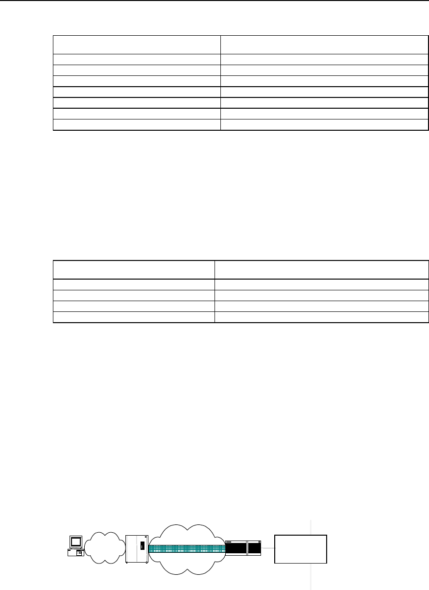
I. Networking requirement
The users can access Intranet of the company through local dial-up access to the
Internet. The tunnel is used to transmit data between NAS and LNS and authenticate
the channel.
II. Networking diagram
VPN user
PSTN/IS
NAS
Headquarter of
the corporation
Internet
Tunne
lLNS
Figure VPN-2-4 Networking diagram of NAS-Initialized VPN

User Manual - Configuration Guide (Volume 3)
Versatile Routing Platform Chapter 2
Configuration of L2TP
2-15
III. Configuration procedure
1) Configuration at user side:
Set user name to “vpnuser”, password to “hello” (the user name and password have
been registered in NAS or company) and dial-in number to”170” at the dial-up terminal.
2) Configuration at NAS side (Quidway A8010 NAS in the case serves as the
equipment at LAC side):
z The dial-in number is usually configured as “170” on A8010.
z On RADIUS access server, set a VPN user with user name “vpnuser” and
password “hello”, and set IP address of the corresponding equipment at LNS side
(In the case, IP address of the port where LNS side and the channel are connected
is 202.38.160.2).
z Define the name of the equipment of local end as A8010 and authenticate the
channel. The channel password is “quidway”.
3) Router configuration (at LNS side)
! Set a VPDN group and configure relative attributes
Quidway(config)# vpdn enable
Quidway(config)# vpdn-group 1
Quidway(config-vpdn1)# local name LNS
Quidway(config-vpdn1)# accept dialin l2tp virtual-template 1 remote A8010
! Set user name and password (consistent with the setting on A8010).
Quidway(config)# user vpnuser password 0 hello
! Start channel authentication and set channel authentication password.
Quidway(config-vpdn2)# l2tp tunnel authentication
Quidway(config-vpdn2)# l2tp tunnel password 0 quidway
! Define an address pool to distribute addresses to dial-in users.
Quidway(config)# ip local poo1 1 192.168.0.2 192.168.0.100
! Configure Virtual-Template 1.
Quidway(config)# interface virtual-template 1
Quidway(config-if-virtual-template1)# ip address 192.168.0.1 255.255.255.0
Quidway(config-if-virtual-template1)# ppp authentication chap
Quidway(config-if-virtual-template1)# peer default ip address pool 1
! Adopt AAA authentication.
Quidway(config)# aaa-enable
Quidway(config)# aaa authentication ppp default local
User Manual - Configuration Guide (Volume 3)
Versatile Routing Platform Chapter 2
Configuration of L2TP
2-16
2.4.2 Client-Initialized VPN
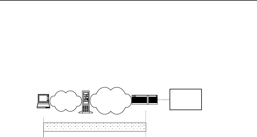
I. Networking requirement
VPN users first connect Internet, then originate tunnel connection request to LNS. After
LNS has accepted the request, a tunnel channel is established between LNS and VPN
users to fulfill data transmission between the users and the company headquarters.
II. Networking diagram
Cleck going
on erramds
Internet
PSTN LNS
Headquarter of
the corportion
NAS
Tunnel
Figure VPN-2-5 Networking diagram of Client-Initialized VPN
III. Configuration procedure
1) Configuration at user side
z Set user name to “vpnuser” and password to “hello” at dial-up terminal (the user
name and password have been registered in company).
z Set IP address of LNS to Internet interface address of the router (In the case, IP
address of the port where LNS side and the channel are connected is
202.38.160.2).
z Modify connection attributes, set the adopted protocol to L2TP and encryption
attribute to be self-defining. And select CHAP authentication to authenticate the
channel whose password is “quidway”.
2) Router configuration (at LNS side)
! Set a VPDN group and configure relative attributes
Quidway (config)# vpdn enable
Quidway (config)# vpdn-group 1
Quidway (config-vpdn1)# local name LNS
Quidway (config-vpdn1)# force-local-chap
Quidway (config-vpdn1)# accept dialin l2tp virtual-template 1 remote vpdnuser
! Set user name and password (consistent with the setting on A8010).
Quidway (config)# user vpnuser password 0 hello
! Start channel authentication and set channel authentication password.
Quidway (config-vpdn1)# l2tp tunnel authentication
Quidway (config-vpdn1)# l2tp tunnel password 0 quidway
! Define an address pool to distribute addresses to dial-in users.
Quidway (config)# ip local poo1 1 192.168.0.2 192.168.0.100
User Manual - Configuration Guide (Volume 3)
Versatile Routing Platform Chapter 2
Configuration of L2TP
2-17
! Configure Virtual-Template 1.
Quidway (config)# interface virtual-template 1
Quidway (config-if-virtual-template1)# ip address 192.168.0.1 255.255.255.0
Quidway (config-if-virtual-template1)# ppp authentication chap
Quidway (config-if-virtual-template1)# peer default ip address pool 1
! Adopt AAA authentication.
Quidway (config)# aaa-enable
Quidway (config)# aaa authentication ppp default local
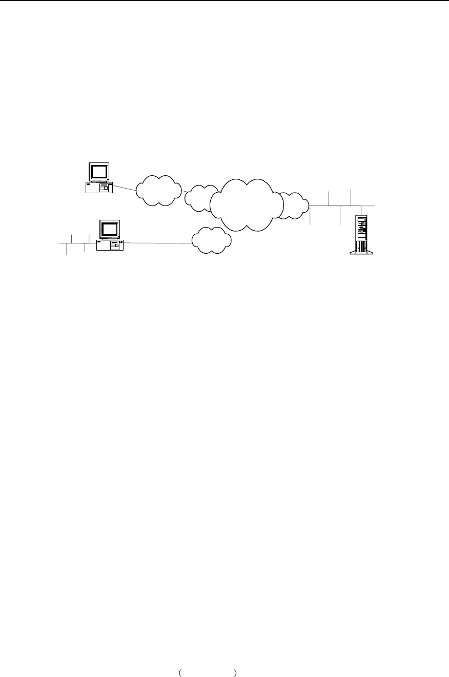
2.4.3 Single User Interconnects Headquarters via Router
I. Networking requirement
A user needs to communicate with headquarters, but the network address of
headquarters is a private address, e.g. 10.8.0.0 network, so the user can not directly
access internal server via Internet. With VPN, the user can access the data of internal
network.
II. Networking diagram
总部
Quidway1
LAC
Quidway2
LNS
PC1InternetTunnel
WAN
Modem
PSTN
PC2
ISDN
Figure VPN-2-6 Networking diagram of single user interconnecting headquarters
III. Configuration procedure
1) Configuration at user side
Set user name to “vpnuser@huawei.com” and password to “hello” at dial-in terminal
(the user name and password have been registered in LAC or company).
Establish a dial-up network with access number “Quidway1”, which receives the
addresses distributed by server. After dial-up window appears, input user name
“vpnuser@huawei.com” and the password “hello”.
2) The configuration of the router Quidway1 (at LAC side) (In the case, IP address of
the port where LNS side and the channel are connected is 202.38.160.2):
! Set a VPDN group and configure relative attributes
Quidway(config)# vpdn enable
Quidway(config)# vpdn-group 1

User Manual - Configuration Guide (Volume 3)
Versatile Routing Platform Chapter 2
Configuration of L2TP
2-18
Quidway(config-vpdn1)# local name LAC
Quidway(config-vpdn1)# request dialin l2tp ip 202.38.160.2 domain huawei.com
Quidway(config-vpdn1)# ppp authentication pap
! Set user name and password.
Quidway(config)# user vpnuser password 0 hello
! Start channel authentication and set channel authentication password.
Quidway(config-vpdn1)# l2tp tunnel authentication
Quidway(config-vpdn1)# l2tp tunnel password 0 quidway
! Set the suffix delimiter of a domain name to '@'.
Quidway(config)# vpdn domain-delimiter suffix @
! Search sequence: first search according to domain name, then according to called
number.
Quidway(config)# vpdn search-order domaindnis
! Adopt AAA authentication.
Quidway(config)# aaa-enable
Quidway(config)# aaa authentication ppp default local
3) The configuration of the router Quidway2 (at LNS side)
! Set a VPDN group and configure relative attributes
Quidway(config)# vpdn enable
Quidway(config)# vpdn-group 1
Quidway(config-vpdn1)# local name LNS
Quidway(config-vpdn1)# force local chap
Quidway(config-vpdn1)# accept dialin l2tp virtual-template 1 remote LAC
! Set user name and password (consistent with the user name and password at LAC
side).
Quidway(config)# user vpnuser@huawei.com password 0 hello
! Start channel authentication and set channel authentication password to “quidway”.
Quidway(config-vpdn1)# l2tp tunnel authentication
Quidway(config-vpdn1)# l2tp tunnel password 0 quidway
! Force local end to perform CHAP authentication
Quidway(config-vpdn1)# force-local-chap
! Set an address pool 1 and the address ranges between 192.168.0.2 and
192.168.0.100.
Quidway(config)# ip local poo1 1 192.168.0.2 192.168.0.100
! Configure Virtual-Template 1.

User Manual - Configuration Guide (Volume 3)
Versatile Routing Platform Chapter 2
Configuration of L2TP
2-19
Quidway(config)# interface virtual-template 1
Quidway(config-if-virtual-template1)# ip address 192.168.0.1 255.255.255.0
Quidway(config-if-virtual-template1)# ppp authentication chap
Quidway(config-if-virtual-template1)# peer default ip address pool 1
! Start AAA authentication.
Quidway(config)# aaa-enable
Quidway(config)# aaa authentication ppp default local
2.5 Fault Diagnosis of L2TP
Before debugging VPN, please confirm that LAC and LNS are on public network. The
connectivity between them can be tested with “ping”.
Fault 1: The users fail to log in.
Troubleshooting: Failure reasons are as follows:
1) Fail to establish the tunnel. The reasons are as follows:
z At LAC side, LNS addresses are improperly set.
z LNS (usually the router) end is not set to receive VPDN group of opposite end of
the channel. For details, view the description of “accept dialin” command.
z Tunnel authentication does not pass. If the authentication is configured, make
sure that channel passwords of both sides are consistent.
z If local end forcedly disconnects the connection and opposite end fails to receive
the corresponding “Disconnect” message due to network transmission error, an
immediately originated tunnel connection will fail. The reason is that both sides
cannot detect the disconnected link within certain time, and the tunnel connections
originated by two opposite ends with the same IP addresses are not allowed.
2) PPP negotiation does not pass. The reasons may be:
z Errors occur to user name and password set at LAC end, or the corresponding
users are not set at LNS end.
z LNS end can not distribute addresses, e.g. the address pool is set to small, or no
address pool is set.
z The types of channel password authentication are inconsistent. The default
authentication type of VPN connection created by Windows 2000 is MSCHAP. If
opposite end does not support MSCHAP, CHAP is recommended.
Fault 2: Fail to transmit data. After the connection is established, no data can be
transmitted, e.g. cannot ping through opposite end.
Troubleshooting: Possible reasons are as follows:
z The address set by LAC is wrong: Generally, LNS distributes addresses, but LAC
can also designate its own address. If the designated address and the address to
be distributed by LNS are not in the same network segment, this problem will
occur. It is recommended that LNS distribute the addresses.
z Network congestion: Congestion occurs to Internet backbone network and
packets are often lost. L2TP transmission is based on UDP (User Datagram
Protocol). UDP does not control message errors. If L2TP is adopted when line
quality is unstable, “Ping” opposite end may fail.

User Manual - Configuration Guide (Volume 3)
Versatile Routing Platform Chapter 3
Configuration of GRE
3-1
Chapter 3 Configuration of GRE
3.1 Brief Introduction to GRE Protocol
I. Brief introduction to the protocol
GRE (Generic Routing Encapsulation) protocol can encapsulate the datagram of some
network layer protocols (e.g. IP and IPX) and enable these encapsulated datagrams to
transmit in another network layer protocol (e.g. IP). GRE is the layer 3 tunnel protocol of
VPN (Virtual Private Network), that is, a technique called as Tunnel is adopted between
protocol layers. The tunnel is a virtual point-to-point connection and can be regarded as
virtual interface only supporting point-to-point connection in actual situation. The
interface provides a channel where the encapsulated datagram can be transmitted.
And it can also encapsulate and de-encapsulate the datagram at both ends of a tunnel.
It's necessary to encapsulate and de-encapsulate it when a message is transmitted on
the tunnel.
1) Encapsulation
As shown in figure VPN-3-6, after receiving IPX datagram, the interface connecting
“Novell group1” first delivers it to be processed by IPX protocol which checks the
destination address domain in IPX header and determines how to route the packet. If it
is found that the destination address of the message will route through the network with
network number 1f (virtual network number of the tunnel), the message will be
transmitted to the tunnel port with network number 1f. After receiving the packet, tunnel
port will perform GRE and then, the packet will be processed by IP module. After IP
header is encapsulated, the packet will be processed by the corresponding network
interface according to destination address and router table.
2) De-encapsulation
The de-encapsulation is opposite to the encapsulation. When an IP message is
received at Tunnel interface, its destination address is checked and the destination is
found to be this router, then the IP header will be removed and processed by GRE
protocol (examine the key, check sum or message serial number). Then after GRE
header is removed, it will be processed by IPX protocol in the same way as processing
an ordinary datagram.
The system receives a datagram to be encapsulated and routed, which is called a
payload. The payload is first encapsulated in the form of GRE to become a GRE
message. Then it is encapsulated in IP message. Thus the IP layer is in full charge of
forwarding the message. The IP protocol which is in charge of the forwarded is often
called delivery protocol or transport protocol.
The form of an encapsulated message is shown in the following figure:
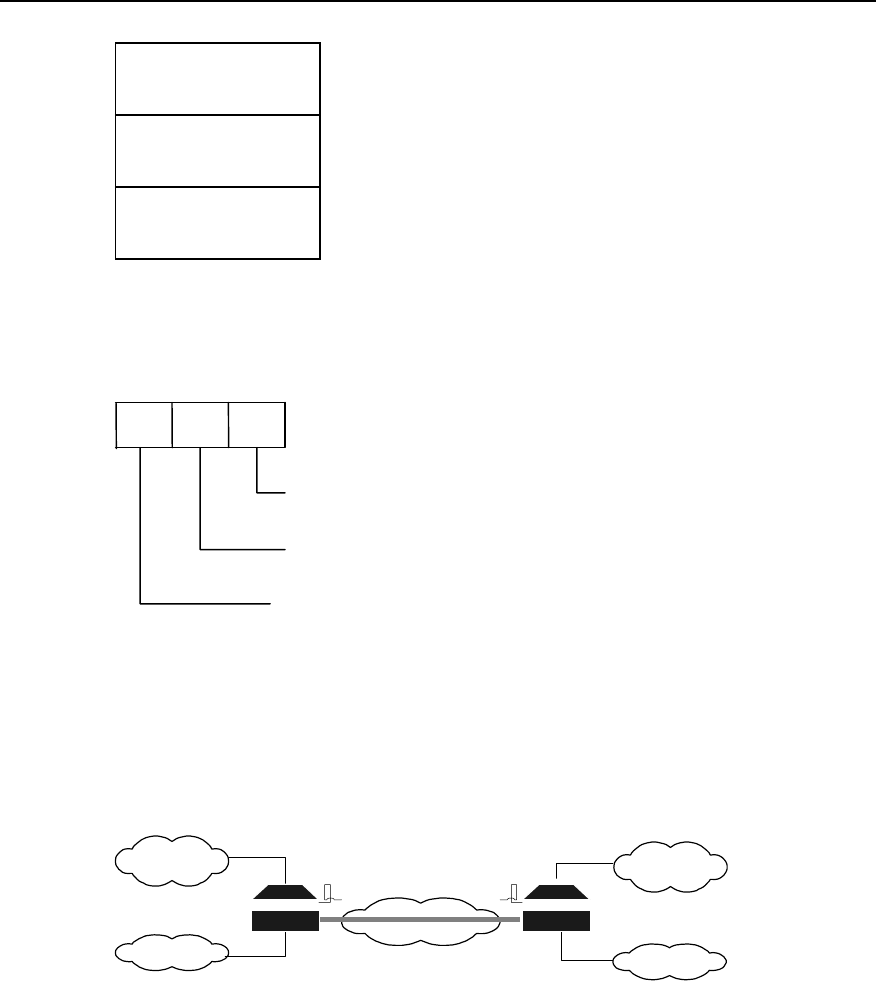
User Manual - Configuration Guide (Volume 3)
Versatile Routing Platform Chapter 3
Configuration of GRE
3-2
Delivery Header
(Transport Protocol)
GRE Header
(Encapsulation Protocol)
Payload Packet
(Passenger Protocol)
Figure VPN-3-1 Encapsulated tunnel message format
For example: The format of IPX transmission message encapsulated in IP Tunnel is as
follows:
IP GRE IPX
Passager Protocol
Carrier Protocol or
Encapsulation Protocol
Transport Protocol
Figure VPN-3-2 Format of transmission message in the tunnel.
II. Applicable range
GRE can fulfill the following several services:
1) Multi-protocol local network transmits via single-protocol backbone network.
INTERNET
Novell IPX
Protocol
Group1
IP protocol
Term 1
Novell IPX
Protocol
Group2
IP protocol
Term 2
Tunnel RouterB
B
RouterA
A
Figure VPN-3-3 Multi-protocol local network transmits via single-protocol backbone network
In the above figure, Group1 and Group2 are the local networks running Novell IPX
protocol. Term1 and Term2 is the local network running IP protocol. The tunnel
encapsulated with GRE protocol is adopted between Router A and Router B. Thus
Group1and Group2 can communicate without affecting each other, so are Term1 and
Term2.
2) Enlarge the operating range of the hop-limited network (e.g. IPX).
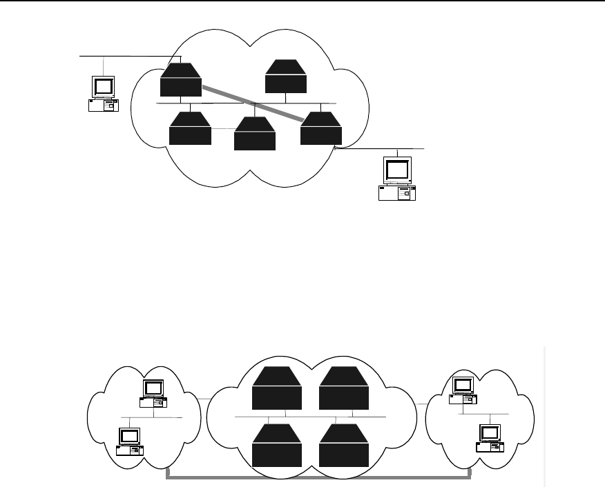
User Manual - Configuration Guide (Volume 3)
Versatile Routing Platform Chapter 3
Configuration of GRE
3-3
Router
r
r
r
r r
Tunnel Router
Router Router Router
Figure VPN-3-4 Enlarge network operating range
When using RIP, if the hop count between two terminals in the above figure is more
than 15, the two terminals can not communicate with each other. When the tunnel is
used in the network, a part of hops can be hidden, enlarging the operating range of the
network.
3) Connect some discontinuous sub-networks to establish VPN.
Tunnel
group2
novell
RouterA
RouterB
Router
Router
group 1
novell
Figure VPN-3-5 Tunnel connects discontinuous sub-networks
The two sub-networks group1 and group2 running Novell IPX protocol are in different
cities. With the tunnel available, the trans-WAN Virtual Private Network can be
established.
In addition, GRE also supports the users to select and record identification key word of
tunnel interface, supports the check of encapsulated message, and supports the use of
synchronous serial numbers to ensure channel safety and correctness of transmission
data.
Because of encapsulation and de-encapsulation on GRE receiving side and
transmitting side and data volume increase caused by encapsulation, GRE will
decrease the forwarding rate of router data to some extent.
3.2 Configuring GRE
3.2.1 GRE Configuration Task List
GRE configuration task list is as follows:
z Create virtual tunnel interface.
z Set the source address of tunnel interface.
z Set the destination address of tunnel interface.
z Set the network address of tunnel interface.

User Manual - Configuration Guide (Volume 3)
Versatile Routing Platform Chapter 3
Configuration of GRE
3-4
z Set the encapsulation mode of tunnel interface message.
z Set the key of tunnel interface.
z Set tunnel interface to check with check sum.
z Set tunnel interface to synchronize datagram serial numbers.
3.2.2 Creating Virtual Tunnel Interface
Perform the following task in global configuration mode.
Table VPN-3-1 Create virtual tunnel interface
Operation Command
Create virtual tunnel interface and enter tunnel configuration mode. interface tunnel number
Cancel virtual tunnel interface. no interface tunnel
By default, no virtual tunnel interface is created. The value of “number” is an integer
between 0 and 4294967295. But tunnel number actually depends on interface sum and
memory status.
3.2.3 Setting the Source Address of Tunnel Interface
After tunnel interface is established, the source address of tunnel channel should be
designated. The source address and destination address of tunnel interface uniquely
identifies a channel.
Perform the following setting in tunnel interface configuration mode.
Table VPN-3-2 Designate the source address of tunnel interface
Operation Command
Designate the source address of tunnel interface. tunnel source ip-address
Cancel the source address of tunnel interface. no tunnel source
3.2.4 Setting the Destination Address of Tunnel Interface
After tunnel interface is established, the destination address of tunnel channel should
be designated. The source address and destination address of tunnel interface
uniquely identifies a channel.
Perform the following setting in tunnel interface configuration mode.
Table VPN-3-3 Designate the destination address of tunnel interface
Operation Command
Designate the destination address of tunnel interface. tunnel destination ip-address
Cancel the destination address of tunnel interface. no tunnel destination

User Manual - Configuration Guide (Volume 3)
Versatile Routing Platform Chapter 3
Configuration of GRE
3-5
3.2.5 Setting the Network Address of Tunnel Interface
Configure network address of tunnel interface so that the channel supports dynamic
routing protocol. The users are recommended to set the network addresses at both
ends of the channel to be in the same network segment.
Perform the following setting in tunnel interface configuration mode.
Table VPN-3-4 Set the network address of tunnel interface
Operation Command
Set the IP address of tunnel interface. ip address ip-address mask
Delete the IP address of tunnel interface. no ip address
Set the IPX address of tunnel interface. ipx network network-number
Delete the IPX address of tunnel interface. no ipx network
3.2.6 Setting the Encapsulation Mode of Tunnel Interface Message
Please configure in tunnel interface configuration mode as below.
Table VPN-3-5 Set the encapsulation mode of tunnel interface message
Operation Command
Set the encapsulation mode of tunnel interface message. tunnel mode gre ip
The encapsulation mode of tunnel interface message is GRE IP by default.
3.2.7 Setting the Identification Key Word of Tunnel Interface
It is stipulated in RFC 1701 that: if the KEY field of GRE header is set, the receiving side
and transmitting side will check the identification key word of the channel. Only when
the set identification key words at both ends of the tunnel are totally identical, can the
check pass, or the message will be discarded.
Perform the configuration in tunnel interface configuration mode.
Table VPN-3-6 Set the identification key word of tunnel interface
Operation Command
Set the identification key word of tunnel interface. tunnel key key-number
Cancel the identification key word of tunnel interface. no tunnel key
By default, the tunnel does not use KEY, an integer ranging 0 to 4294967295.
3.2.8 Setting Tunnel Interface to Check with Check Sum
It is stipulated in RFC 1701 that: if the “Checksum” place of GRE header is set, the
check sum is valid. The transmitting side calculates the check sums of GRE header
and payload. The receiving side calculates the check sum of the received message and

User Manual - Configuration Guide (Volume 3)
Versatile Routing Platform Chapter 3
Configuration of GRE
3-6
compares it with the check sum in the message. If the two check sums are identical, the
message will be further processed, or it will be discarded.
If only one end of the tunnel is configured to check with the check sum, the message
will not be checked with check sum. Only when both ends of the tunnel are configured
to check with the check sum, can the message be checked with the check sum.
Perform the following task in tunnel interface configuration mode.
Table VPN-3-7 Set tunnel interface to check with check sum
Operation Command
Set tunnel interface to check with check sum. tunnel checksum
Disable tunnel interface to check with check sum. no tunnel checksum
Disable tunnel interface to check with check sum by default.
3.2.9 Setting Tunnel Interface to Synchronize Datagram Serial Number
It is stipulated in RFC 1701 that: if “sequence-datagram” in GRE header is set, both
receiving side and transmitting side will synchronize serial numbers. The synchronized
message should be further processed, or it is discarded.
With the serial numbers, the message is unreliable but in order. The receiving end
establishes serial numbers for the message which is received by local end and
successfully de-encapsulated (The serial numbers are integers between 0 and 232–1
and the serial number of the first packet is 0). After the channel is established, the serial
numbers will be accumulated and cyclically counted. If the receiving end receives a
message whose serial number is less than or equal to that of the message received last
time, the packet will be considered as illegal. If the receiving end receives an orderless
message, the packet will be automatically discarded.
Only when the synchronization mechanism to set/disable serial numbers is established
at both ends of the tunnel, can the channel be established.
Perform the following task in tunnel interface configuration mode.
Table VPN-3-8 Set the tunnel to synchronize datagram serial numbers
Operation Command
Set tunnel interface to synchronize serial numbers. tunnel sequence-datagrams
Disable tunnel interface to synchronize serial numbers. no tunnel sequence-datagrams
Disable tunnel interface to synchronize datagram serial numbers by default.
3.3 Monitoring and Maintenance of GRE
Perform the following task in privileged user mode.
Table VPN-3-9 Monitoring and maintenance of GRE
Operation Command
Show the working status of tunnel interface. show interface tunnel [tunnel-number]

User Manual - Configuration Guide (Volume 3)
Versatile Routing Platform Chapter 3
Configuration of GRE
3-7
1) Show the status of designated tunnel interface.
Quidway# show interface tunnel 1
Tunnel1 is up, line protocol is up
Internet address is 3.1.1.1 255.255.255.0
10 packets input, 640 bytes
0 input errors, 0 broadcast, 0 drops
10 packets output, 640 bytes
0 output errors, 0 broadcast, 0 no protocol
The above information means that: The network address of “Tunnel1” is 3.1.1.1. 0
message is received. The number of received error message and broadcast message
is 0. There is no discarded message. The number of transmitted messages is 0. There
is no the message with error output, the broadcast message and the message with
unknown protocol type
2) Show router table of the system.
Quidway(config)# show ip route
Routing Tables:
Destination/Mask Proto Pref Metric Nexthop Interface
3.1.1.0/24 Direct 0 0 3.1.1.1 Tunnel1
10.10.1.0/24 Direct 0 0 10.10.1.3 Serial0
10.10.1.3/32 Direct 0 0 10.10.1.3 Serial0
10.110.1.0/24 Direct 0 0 10.110.1.100 Ethernet0
20.20.1.0/24 Static 60 0 10.10.1.3 Serial0
20.110.1.0/24 Static 60 0 3.1.1.2 Tunnel1
The above information shows that the router table of the system includes the route of
the interface Tunnel1.
3.4 Typical Configuration of GRE
I. Networking requirement
VPN should be built across WAN for the operation of Novell IPX’s two subnets group1
and group2. It can be implemented by using GRE.
II. Networking diagram
IPX protocol
Group1
INTERNET IPX protocol
Group2
Tunnel
Router A Router B
Figure VPN-3-6 Networking diagram of GRE application
III. Configuration procedure
Configure router A:
! Activate IPX.
RouterA(config)# ipx routing a.a.a
! Configure interface “Ethernet0”.
RouterA(config)# interface ethernet 0

User Manual - Configuration Guide (Volume 3)
Versatile Routing Platform Chapter 3
Configuration of GRE
3-8
RouterA(config-if-Ethernet0)# ip address 10.1.1.1 255.255.255.0
RouterA(config-if-Ethernet0)# ipx network 1e
! Enter tunnel source interface.
RouterA(config)# interface serial 0
RouterA(config-if-Serial0)# ip address 192.13.2.1 255.255.255.0
! Create virtual tunnel interface and configure tunnel interface
RouterA(config)# interface tunnel 0
RouterA(config-if-tunnel0)# ip address 10.1.2.1 255.255.255.0
RouterA(config-if-tunnel0)# ipx network 1f
! Designate that tunnel working mode is GRE and transmission protocol is IP.
RouterA(config-if-tunnel0)# tunnel mode gre ip
! Configure the source address of tunnel interface (It should be IP address of Serial0 of
RouterA).
RouterA(config-if-tunnel0)# tunnel source 192.13.2.1
! Configure the opposite end IP address of tunnel interface (It should be IP address of
Serial0 of RouterB).
RouterA(config-if-tunnel0)# tunnel destination 131.108.5.2
! Configure a static route to Group2.
RouterA(config)# ipx route 31 1f.a.a.a 30000 15
The configurations of Router B are as follows:
! Activate IPX.
RouterB(config)# ipx routing b.b.b
! Configure interface “Ethernet0”.
RouterB(config)# interface ethernet 0
RouterB(config-if-Ethernet0)# ip address 10.1.3.1 255.255.255.0
RouterB(config-if-Ethernet0)# ipx network 31
! Enter tunnel source interface.
RouterB(config)# interface serial 0
RouterB(config-if-Serial0)# ip address 131.108.5.2 255.255.255.0
! Create and enter “Tunnel0” interface configuration mode.
RouterB(config)# interface tunnel 0
RouterB(config-if-tunnel0)# ip address 10.1.2.2 255.255.255.0
RouterB(config-if-tunnel0)# ipx network 1f
! Designate that tunnel working mode is GRE and transmission protocol is IP.
RouterB(config-if-tunnel0)# tunnel mode gre ip
! Configure the source address of Tunnel0 interface (It should be IP address of Serial0
of RouterB).
RouterB(config-if-tunnel0)# tunnel source 131.108.5.2
! Explain the opposite end address of Tunnel0 interface (It should be IP address of
Serial0 of RouterA).
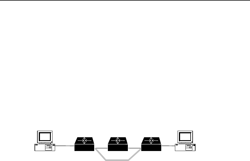
User Manual - Configuration Guide (Volume 3)
Versatile Routing Platform Chapter 3
Configuration of GRE
3-9
RouterB(config-if-tunnel0)# tunnel destination 192.13.2.1
! Configure a static route to Group1.
RouterB(config)# ipx route 1e 1f.b.b.b 30000 15
3.5 Troubleshooting GRE
As GRE configuration is relatively simple, only the consistency of the configuration
needs to be noted. Here, analyze a relative error, as shown in the following figure:
Fault 1: The interfaces at both ends of the tunnel are properly configured and both ends
of the tunnel can be “pinged” through, but PC A and PC B can not be “pinged” through.
Troubleshooting: In this case, mainly check whether there is a route passing through
tunnel interface. That is, at RouterA, a route to 10.2.0.0/16 passes through Tunnel0
interface; at RouterB, a route to 10.1.0.0/16 passes through Tunnel0 interface (fulfilled
by adding static route).
PC A PC B
Serial0 Serial1
tunnel
10.1.1.1 10.2.1.1
Router A Router BRouter C
Figure VPN-3-7 Networking group of GRE troubleshooting example
HUAWEI®
VRP
User Manual – Configuration Guide
Volume 3
08 – Reliability Configuration (LC)

User Manual - Configuration Guide (Volume 3)
Versatile Routing Platform Table of Contents
i
Table of Contents
Chapter 1 Configuration of Backup Center ............................................................................... 1-1
1.1 Backup Center Overview .................................................................................................. 1-1
1.2 Configuring the Backup Center......................................................................................... 1-1
1.2.1 Configuration Task List .......................................................................................... 1-1
1.2.2 Entering the Configuration Mode of the Main Interface to be Backed Up.............. 1-1
1.2.3 Specifying Backup Interface and Priority Used by the Main Interface ................... 1-2
1.2.4 Setting Delay Time for Switchover Between Main and Backup Interface.............. 1-3
1.2.5 Setting State-Judging Conditions for Logic-Channel Main Interface ..................... 1-3
1.2.6 Setting State-Judging Conditions for Logic-Channel Backup Interface ................. 1-4
1.2.7 Configuring Routes for Main and Backup Interfaces ............................................. 1-4
1.3 Monitoring and Maintaining of Backup Center.................................................................. 1-5
1.4 Typical Configuration of Backup Center ........................................................................... 1-5
1.4.1 An example of Backup Between Interfaces ........................................................... 1-5
1.4.2 An Example of Multiple Backup Interfaces ............................................................ 1-5
1.4.3 An Example of Logical Channel Backup Interface................................................. 1-5
1.4.4 An Example of Multiple Backup Interfaces with a Logical Channel ....................... 1-6
Chapter 2 Configuration of HSRP............................................................................................... 2-1
2.1 HSRP Overview ................................................................................................................ 2-1
2.2 Configuring HSRP............................................................................................................. 2-2
2.2.1 Configuration Task List .......................................................................................... 2-2
2.2.2 Starting HSRP Function ......................................................................................... 2-2
2.2.3 Setting Router’s Priority in HSRP Hot Standby Group........................................... 2-3
2.2.4 Setting Router’s Preemption Mode in HSRP Standby Group................................ 2-3
2.2.5 Setting HSRP Authorization Word ......................................................................... 2-3
2.2.6 Setting HSRP Timer............................................................................................... 2-4
2.2.7 Monitoring the Specified Interface ......................................................................... 2-4
2.2.8 Using Actual Interface MAC Address..................................................................... 2-5
2.2.9 Modifying Virtual MAC Address ............................................................................. 2-5
2.3 Monitoring and Maintaining HSRP.................................................................................... 2-6
2.4 Typical Configurations of HSRP ....................................................................................... 2-6
2.4.1 An example for single hot standby group configuration ......................................... 2-6
2.4.2 An example for setting HSRP to monitor a specified interface .............................. 2-8
2.4.3 An example for multiple hot standby groups configuration .................................... 2-9
2.5 Fault Diagnosis and Troubleshooting of HSRP .............................................................. 2-10

User Manual - Configuration Guide (Volume 3)
Versatile Routing Platform Chapter 1
Configuration of Backup Center
1-1
Chapter 1 Configuration of Backup Center
1.1 Backup Center Overview
To enhance network’s reliability, VRP provides perfect backup functions through the
use of Backup Center.
z Interfaces that can be backed up are called main interfaces. Every physical
interface or sub-interface on a router can serve as a main interface. A logical
channel such as X.25 on any interface or a virtual circuit of a frame relay can also
serve as a main interface.
z Any physical interface, virtual interface template, or a logical channel on an
interface other than the Ethernet interface of a router can serve as the backup
interface of aother interface or logical channel.
z A main interface can be provided with multiple backup interfaces; when the main
interface gets faulty, backup interfaces can take over the main interface’s work in
an order based on their priority.
z Interfaces (such as ISDN BRI and ISDN PRI interfaces) that have multiple
physical channels can provide backups to multiple main interfaces by using Dialer
Map.
1.2 Configuring the Backup Center
1.2.1 Configuration Task List
Follow the steps below to configure VRP backup center.
z Enter the configuration mode of the main interface to be backed up.
z Specify the backup interface and priority used by the main interface.
z Set the delay time for the switchover between main and backup interfaces.
z Set state-judging conditions when the main interface is a logical channel.
z Set the state-judging conditions when the backup interface is a logical channel.
z Configure routes for main and backup interfaces.
1.2.2 Entering the Configuration Mode of the Main Interface to be Backed Up
On a Quidway router, not only every physical interface or sub-interfaces of the router,
but every virtual circuit of X.25 or frame relay can work as a main interface. If the main
interface is a physical interface or sub-interface, please use the following commands in
global configuration mode to enter the configuration mode of the interface.
Table LC-1-1 Enter the configuration mode of the main interface
Operation Command
Enter the configuration mode of the main interface interface interface-type interface-number
Here, interface-type specifies the interface type of the physical interface or sub-
interface, interface-number specifies the interface number of the physical interface or
sub-interface. Combined, they specify a physical interface or sub-interface.

User Manual - Configuration Guide (Volume 3)
Versatile Routing Platform Chapter 1
Configuration of Backup Center
1-2
If the main interface is a virtual circuit, it should be treated differently depending on the
type of the virtual circuit: firstly, specify its logical channel number in the configuration
mode of the physical interface to which it’s subordinate; then enter corresponding
logical channel configuration mode. logic-channel-number ranges between 0 to 255.
Please use following commands in corresponding configuration modes.
Table LC-1-2 Enter the logical channel configuration mode
Operation Command
Specify logical channel number for X.25 virtual circuit. x25 map protocol address x.121-address lin logic-
channel-number [ lin logic-channel-number ... ]
Specify logical channel number for frame relay virtual
circuit frame-relay map protocol address dlci lin logic-
channel-number [ lin logic-channel-number ... ]
Enter corresponding logical channel configuration mode. logic-channel logic-channel-number
1.2.3 Specifying Backup Interface and Priority Used by the Main Interface
Except Ethernet interface, any physical interface or virtual interface template, or a
certain logical channel (including virtual circuit or Dialer Map) can work as a backup
interface of the main interface. Please use the following commands in the configuration
mode of the main interface backed up.
Table LC-1-3 Specify backup interface and priority used by the main interface
Operation Command
Specify a physical interface or virtual interface template, except
Ethernet interface, to back up the main interface; its priority can
also be set here.
backup interface interface-type interface-
number [priority]
Specify a logical channel to back up the main interface, its priority
can also be set here. backup logic-channel logic-channel-
number [priority]
Here, interface-type interface-number specifies a physical interface or virtual interface
template; the value range of logic-channel-number is 1~255; the value range of priority
of the backup interface is 0~255, with 0 as default. The larger the value, the higher the
priority, i.e., when the main interface gets faulty, its work will be first taken over by an
interface with the highest priority.
If the main interface has multiple backup interfaces, simply repeat the above operations.
In addition, if the backup interface is a logical channel, the logical channel should be
made to correspond to the actual virtual circuit or Dialer Map.
Please use the commands below to specify corresponding logical channel numbers for
these virtual circuits or Dialer Map in the configuration mode of the physical interface to
which they are subordinate.

User Manual - Configuration Guide (Volume 3)
Versatile Routing Platform Chapter 1
Configuration of Backup Center
1-3
Table LC-1-4 Establish a corresponding relation between logical channel and virtual circuit or Dialer Map
Operation Command
Specify a logical channel number for X.25 virtual circuit x25 map protocol address x.121-address lin logic-
channel-number
Specify a logical channel number for frame relay virtual
circuit frame-relay map protocol address dlci lin logic-
channel-number
Specify a logical channel number for Dialer Map dialer map protocol next-hop-address dialer-string
lin logic-channel-number
1.2.4 Setting Delay Time for Switchover Between Main and Backup Interface
When the state of the main interface changes from up to down, the system doesn’t
switch to backup interface right away, but wait for a preset time delay instead. The
system will switch to the backup interface only if the state of the main interface remains
down after the delay time runs out; if the main interface recovers within the delay time,
the system will not switch to the backup interface.
When the state of the main interface changes from down to up, the system doesn’t
switch to the main interface right away, but wait for a preset time delay instead. The
system will switch back to the main interface only if the state of the main interface
remains ‘up’ after the delay time runs out; if the main interface restores its down state
again within the delay time, the system will not switch to the main interface
To run following commands normally, user should run those commands firstly, which
specify a physical interface or virtual interface template, or a certain logical channel,
except Ethernet interface, to backup main interface (backup interface/logic-
channel).
Please use the following command in the configuration mode of the main interface
backed up.
Table LC-1-5 Set the delay time for the switchover between main and backup interfaces
Operation Command
Set the delay time for switchover between main and backup
interfaces backup delay enable-delay disable-delay
Restore to the default value of the delay time for switchover
between main and the backup interfaces no backup delay
Here, enable-delay is the delay time for the main interface to switch over to backup
interface, the value ranges from 0 to 65535 seconds, and the default value is 0,
indicating an immediate switchover. disable-delay is the delay time for backup interface
to switch over to the main interface, the value ranges from 0 to 65535 seconds, and the
default value is 0, indicating an immediate switchover.
1.2.5 Setting State-Judging Conditions for Logic-Channel Main Interface
When the main interface is a logical channel, the logical channel is regarded as down
after a specified number of unsuccessful calls. After it switches over to the backup
interface, regular inspections at specified time interval must be made on the state of the
logical channel to check if it’s recovered its up state or not.

User Manual - Configuration Guide (Volume 3)
Versatile Routing Platform Chapter 1
Configuration of Backup Center
1-4
To run following commands normally, user should run those commands firstly, which
specify a physical interface or virtual interface template, or a certain logical channel,
except Ethernet interface, to backup main interface (backup interface/logic-
channel).
Please use the following command in the configuration mode of the logical channel
Table LC-1-6 Set the state-judging conditions when the main interface is a logical channel
Operation Command
Set the condition for judging the logical channel as down: the logical channel
is regarded as down after the specified number of unsuccessful calls. backup state-down number
After system switches to backup interface, interval-time is set to make regular
inspections so as to check whether the original logical channel has recovered
its “up” state. backup state-up interval-time
By default, the number of call and state checking interval-time are not configured.
1.2.6 Setting State-Judging Conditions for Logic-Channel Backup Interface
If the main interface has multiple backup interfaces of which one is a logical channel,
it’s necessary to judge whether the logical channel is down or up before opening it. If it
is down, open the hypo-higher priority backup interface in an order of priority; after the
logical channel changes to up, it’s required to switch from the hypo-higher priority
backup interface of a low priority to this logical channel.
To run following commands normally, the command that specifies logical channel
backup main interface (backup logic-channel) must be ran at first.
Please use the following commands in the configuration mode of the logical channel
Table LC-1-7 Set the state-judging conditions when the backup interface is a logical channel
Operation Command
Set the condition for judging the backup logical channel as down: the backup
logical channel is regarded as down after the specified number of
unsuccessful calls. backup state-down number
Interval-time is set to make regular inspections so as to check if the backup
logical channel has restored to the up state or not. backup state-up interval-time
By default, the number of call and state checking interval-time are not configured.
1.2.7 Configuring Routes for Main and Backup Interfaces
By using command ip route in the global configuration mode, it is possible to configure
routes to the destination network segment through the main interface and all the
backup interfaces. Please refer to relevant chapters of “Network Protocol
Configuration” in this manual for details about the command ip route.

User Manual - Configuration Guide (Volume 3)
Versatile Routing Platform Chapter 1
Configuration of Backup Center
1-5
1.3 Monitoring and Maintaining of Backup Center
Table LC-1-8 monitoring and maintenance of backup center
Operation Command
Turn on the backup debug debug backup { event | packet }
1.4 Typical Configuration of Backup Center
1.4.1 An example of Backup Between Interfaces
I. Networking requirements
Take interface Serial 2 as the backup interface for interface Serial 1.
II. Configuration procedure
! Enter the configuration mode of Serial 1.
Quidway(config)# interface serial 1
! Set Serial 2 as its backup interface.
Quidway(config-if-Serial1)# backup interface serial 2
! Set the time for switchover between main and backup interfaces as 10 seconds.
Quidway(config-if-Serial1)# backup delay 10 10
1.4.2 An Example of Multiple Backup Interfaces
I. Networking requirements
Take both interfaces Serial 1 and Serial 2 as the backup interface of interface Serial 0,
and use interface Serial 1 as a preference.
II. Configuration procedure
! Enter the configuration mode of Serial 0.
Quidway(config)# interface serial 0
! Set interfaces Serial 1 and Serial 2 as the backup interfaces, their priorities being 30
and 20 respectively.
Quidway(config-if-Serial0)# backup interface serial 1 30
Quidway(config-if-Serial0)# backup interface serial 2 20
1.4.3 An Example of Logical Channel Backup Interface
I. Configuration requirements

User Manual - Configuration Guide (Volume 3)
Versatile Routing Platform Chapter 1
Configuration of Backup Center
1-6
Set interface Serial 1 as the backup interface for an X.25 virtual circuit on interface
Serial 0.
II. Configuration procedure
! Configure that interface Serial 0 encapsulates X.25 virtual circuit and specify its IP
address and X.121 address.
Quidway(config)# interface serial 0
Quidway(config-if-Serial0)# encapsulation x25
Quidway(config-if-Serial0)# ip address 1.1.1.2 255.0.0.0
Quidway(config-if-Serial0)# x25 address 1
! Match an X.25 virtual circuit on interface Serial 0 with logical channel 10.
Quidway(config-if-Serial0)# x25 map ip 2.2.2.3 2 lin 10
! Enter the configuration mode of logical channel 10.
Quidway(config-if-Serial0)# logic-channel 10
! Specify interface Serial 1 as the backup interface of this logical channel.
Quidway(config-logic-channel10)# backup interface serial 1
! Set the time interval as 10 seconds for judging the logical channel as up.
Quidway(config-logic-channel10)# backup state-up 10
1.4.4 An Example of Multiple Backup Interfaces with a Logical Channel
I. Configuration requirements
Take both logical channel 3 on interface Serial 1 and interface Serial 2 as the backup
interfaces of logical channel 5 on interface Serial 0.
II. Configuration procedure
! Configure that interface Serial 0 encapsulates X.25 virtual circuit and specify its IP
address and X.121 address.
Quidway(config)# interface serial 0
Quidway(config-if-Serial0)# encapsulation x25
Quidway(config-if-Serial0)# ip address 1.1.1.2 255.0.0.0
Quidway(config-if-Serial0)# x25 address 1
! Match an X.25 virtual circuit on interface Serial 0 with logical channel 5.
Quidway(config-if-Serial0)# x25 map ip 2.2.2.3 2 lin 5
! Configure that interface Serial 1 encapsulates X.25 virtual circuit and specify its IP
address and X.121 address.
Quidway(config-if-Serial0)# interface serial 1
Quidway(config-if-Serial1)# encapsulation x25
Quidway(config-if-Serial1)# ip address 3.3.3.4 255.0.0.0

User Manual - Configuration Guide (Volume 3)
Versatile Routing Platform Chapter 1
Configuration of Backup Center
1-7
Quidway(config-if-Serial1)# x25 address 3
! Match logical channel 3 with an X.25 virtual circuit on interface Serial 1.
Quidway(config-if-Serial1)# x25 map 4.4.4.5 4 lin 3
! Enter the configuration mode of logical channel 5 and set logical channel 3 and
interface Serial 1 as its backup interfaces, their priorities being 50 and 20 respectively.
Quidway(config-if-Serial1)# logic-channel 5
Quidway(config-logic-channel5)# backup logic-channel 3 50
Quidway(config-logic-channel5)# backup interface serial 2 20
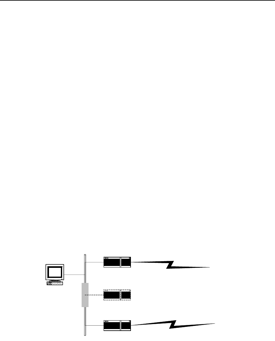
User Manual - Configuration Guide (Volume 3)
Versatile Routing Platform Chapter 2
Configuration of HSRP
2-1
Chapter 2 Configuration of HSRP
2.1 HSRP Overview
HSRP (Hot Standby Router Protocol), is a reliability protocol based on hot standby
mechanism. It aims, when using a router as the gateway, to enhance the connection
reliability between the network and the outside through hot standby mechanism. It will
be suffice to configure HSRP on a router, which does not affect the local host and there
is no need to make configuration on the local host.
Put two or more routers into a hot standby group to implement HSRP: from the local
host’s point of view, this hot standby group is a virtual router itself, with its own IP
address (a virtual IP address), and the local hosts use this virtual router as a gateway.
In the hot standby group, there is one active Router. It does the work of a virtual router
such as forwarding the local host’s data and messages to the virtual router. And there is
a router in the standby state that is ready to switch over to the active state at any time
when it is necessary. The other routers (if any) in the group are in a listen state. The
state of non-active routers (standby or listen) are determined by their own priority, i.e.,
the router with the highest priority will be in standby state, which leaves the other
routers to be in a listen state. If they have the same priority, then the one with a bigger
Ethernet interface IP address will be in a standby state, leaving the rest ones to be in a
listen state.
When fault occurs, a standby router will take over the work of the active router, and one
of the rest routers (if any) with the highest priority will be selected as the standby router.
Thus, the local host can keep using this virtual router gateway without any
modifications.
Ethernet
Router A (Active)
Virtual router
Router B (Standby)
IP address: 202.38.160.1
IP address: 202.38.160.2
Virtual IP address: 202.38.160.10
Virtual MAC address: 00-E0-FC-00-5F-01
Workstation
Gateway IP address:
202.38.160.10
Figure LC-2-1 Schematic diagram of HSRP application
In this figure, Router A and Router B form a hot standby group, which has the following
workflow:
A certain local host takes the IP address 202.38.160.10 of the hot standby group—
virtual router as its own gateway address. Before transmitting messages through
gateway, it sends out an ARP request in the hope of obtaining a virtual MAC address

User Manual - Configuration Guide (Volume 3)
Versatile Routing Platform Chapter 2
Configuration of HSRP
2-2
corresponding to this IP address; and as Router A is active now, it will respond to this
ARP request by informing the host that this MAC address is 00-E0-FC-00-5F-01.
In this way all the messages sent by the host to the gateway will use this MAC address
as a destination MAC address. Router A will receive these messages, forward them, or
process them in some other ways.
At the same time, Router A will send out Hello messages periodically to keep its state
informed to Router B. If Router B doesn’t receive the messages sent by Router A in the
set time, it will conclude that Router A isn’t usable anymore. Thus Router B changes to
the active state and receives all the messages sent by the local host to virtual router
gateways (i.e., to IP address 202.38.160.10 or MAC address 00-E0-FC-00-5F-01),
forwards them, processes them in some other ways. And the local host can still use
gateway as usual (i.e., use 202.38.160.10 as its own gateway IP address).
2.2 Configuring HSRP
2.2.1 Configuration Task List
HSRP protocol is designed to support multicast or broadcast LAN such as Ethernet.
Therefore HSRP configuration is performed in the configuration mode of the Ethernet
interface.
The HSRP configuration tasks of VRP include:
z Start HSRP function
z Set router’s priority in HSRP Hot Standby group
z Set Router’s preemption working mode in HSRP Hot Standby group
z Set HSRP authorization word
z Set HSRP timer
z Set to monitor the specified interface.
z Set to use the actual interface MAC address.
z Modify virtual MAC address
2.2.2 Starting HSRP Function
Start Ethernet interface’s HSRP function in the router to add a Hot Standby group to a
specified LAN segment. It is necessary to specify a Hot Standby group number and
virtual IP address.
Please use the following commands in the configuration mode of Ethernet interface.
Table LC-2-1 Start HSRP function
Operation Command
Start HSRP function Standby [group-number] ip [virtual-ip-address]
Prohibit HSRP function No standby [group-number] ip [virtual-ip-address]
Group-number is the number of the Standby group, with a value range of 0~255 and a
default value of 0.virtual-ip-address is the virtual IP address. If the virtual IP address is
not specified, the router will not participate in the backup process until it receives the
virtual IP address from among the messages sent by an active router in the Hot
Standby group. Note that the virtual-ip-address should be at the same network
segment as the interface’s IP address.

User Manual - Configuration Guide (Volume 3)
Versatile Routing Platform Chapter 2
Configuration of HSRP
2-3
Note:
1) Please note that if some Ethernet interface configured with HSRP has its IP address changed, its HSRP
will become disabled.
2) If a route is configured with several HSRP Hot Standby Group, then there can be at most one Hot
Standby Group without specified virtual IP address.
2.2.3 Setting Router’s Priority in HSRP Hot Standby Group
HSRP determines the state of every router in Hot Standby group according to their
priority parameters, i.e., a router with both the highest priority and a virtual IP address
will be an active router, leaving others in the standby or listen state.
Please use the following command in the Ethernet interface configuration mode.
Table LC-2-2 Set router’s priority in HSRP Hot Standby group
Operation Command
Set router’s priority in HSRP Hot Standby group. standby [group-number] priority [priority-value]
Priority-value is its priority, the larger the value, the higher the priority, and it has a value
range of 0~255 and a default value of 100.
2.2.4 Setting Router’s Preemption Mode in HSRP Standby Group
Once a Router in the Standby group becomes an active Router, as long as the active
Router does not break down, other Routers will not become active even if they have a
higher priority level later on, except that they are set in a preemption working mode. If a
router is set in a preemption mode in an HSRP hot standby group, once it finds out that
it has a higher priority than the present active router, it will ‘preempt ’ to become an
active router. The previous active router will therefore exit its active state to become a
‘standby’ or ‘listen’ router.
Please use the following commands in Ethernet interface configuration mode.
Table LC-2-3 Set router’s priority in HSRP hot standby group
Operation Command
Set router’s preemption working mode in HSRP hot standby group. standby [group-number] preempt
Forbid router’s preemption working mode in HSRP hot standby group. no standby [group-number] preempt
By default it means no router is set in a preemption mode in any HSRP hot standby
group.
2.2.5 Setting HSRP Authorization Word
HSRP authorization word is used to check other routers’ validity in the same hot
standby group.
Please use the following commands in the Ethernet interface configuration mode.

User Manual - Configuration Guide (Volume 3)
Versatile Routing Platform Chapter 2
Configuration of HSRP
2-4
Table LC-2-4 Set HSRP authorization word
Operation Command
Set HSRP authorization word standby [group-number] authentication [string]
By default, the value of group-number is 0 and the authorization word string is
“quidway”. The length of the authorization word should not exceed 8 characters.
Note:
The same authorization word must be set in the same hot standby group.
2.2.6 Setting HSRP Timer
Routers in the same HSRP hot standby group check each other’s state through hello-
time packets sent among each other: if no hello-packet is received from a router during
a hold-time, this router is then considered as being turned off or some fault has
occurred. By setting HSRP timer hello-time and hold-time are adjusted for sending
hello-packets.
Please use the following commands in the Ethernet interface configuration mode.
Table LC-2-5 Set HSRP timer
Operation Command
Set HSRP timer standby [group-number] timers [hello-time] [hold-time]
Both hello-time and hold-time have a value range of 1~255 and have second as their
unit, their default values are 3 and 10 seconds respectively.
Note:
The same hello-time and hold-time must be set in the same hot standby group and hold-time must be
longer than hold-time.
2.2.7 Monitoring the Specified Interface
The interface monitoring function of HSRP expands backup function satisfactorily:
backups are available not only for a router when it goes wrong but for an interface of a
router in case it’s not usable. After the interface monitoring function is set, the router’s
priority will be adjusted dynamically according to the state of the interface that is under
monitoring. Once the monitored interface becomes unavailable, the priority value of
this router will be reduced, so that another router with a more stable interface state in
the same backup group can become the active one, or preempt to be the active one.
Please use the following commands in the Ethernet interface configuration mode.

User Manual - Configuration Guide (Volume 3)
Versatile Routing Platform Chapter 2
Configuration of HSRP
2-5
Table LC-2-6 Monitor the specified interface
Operation Command
Monitor the specified interface standby [group-number] track interface-type interface-
number [priority-reduced]
Cancel the monitoring of the specified interface no standby [group-number] track interface-type interface-
number [priority-reduced]
This command is used to monitor the interface specified by interface-type interface-
number, of which interface-type specifies the type of a physical interface or sub-
interface, while interface-number specifies the number of a physical interface or sub-
interface.
If the state of the interface turns unavailable, its priority will be reduced by a value
specified by priority-reduced. The value range of priority-reduced is 1~255, with 10 as
default.
2.2.8 Using Actual Interface MAC Address
When the host uses HSRP virtual router, it uses both virtual IP address and virtual MAC
address of the HSRP virtual router. By default, each HSRP hot standby group takes the
reserved special MAC address as virtual MAC address in order to guarantee that the
hot standby group is transparent to the host. However, users can also set HSRP hot
standby group to use actual MAC address (Burned in Address BIA) of the active router.
Please use the following commands in the Ethernet interface configuration mode.
Table LC-2-7 Set to use the actual interface MAC address
Operation Command
Use the actual MAC address. standby use-bia
Use the virtual MAC address. No standby use-bia
Note:
1. When BIA is used, the same Ethernet interface must not participate in multiple hot standby groups.
2. The use of BIA might lead to a change in the state of HSRP.
2.2.9 Modifying Virtual MAC Address
Virtual MAC addresses of HSRP hot standby group are different with different
manufacturers. Virtual MAC addresses can be modified to achieve interworking with
routers from different manufacturers.
Please use the following commands in the Ethernet interface configuration mode.
Table LC-2-8 Modify virtual MAC address
Operation Command
Set to use other virtual MAC addresses. standby use-ovmac [ xx-xx-xx-xx-xx ]
Reuse default virtual MAC address no standby use-ovmac

User Manual - Configuration Guide (Volume 3)
Versatile Routing Platform Chapter 2
Configuration of HSRP
2-6
xx-xx-xx-xx-xx indicates the first 5 bytes of other virtual MAC addresses, the last byte
being the hot standby group’s number. The setting is valid for all HSRP hot standby
groups on the configured Ethernet interface.
2.3 Monitoring and Maintaining HSRP
After the configuration, the following commands can be used to turn on the debug
switch of HSRP or display relevant information of HSRP so as to monitor and maintain
HSRP.
Table LC-2-9 Monitoring and maintenance of HSRP
Operation Command
Debug HSRP(in the mode of privileged users) debug standby
Display relevant information of HSRP (in any configuration mode) show standby
z Show relevant HSRP information
Quidway# show standby
Ethernet0 |Group Number : 1
State : Init
Hot Standby IP : 103.1.1.5
Priority : 100 Preempt : no
Hold Time : 10 Hello Time: 3
Use Virtual Mac Address : 00-e0-fc-00-5f-01
The above information includes the standby group that the interface belongs to, state,
virtual IP address, priority, preemption, hold-time, hello-time, and virtual MAC address.
Note:
As output of the debugging information affects router’s running efficiency, please don’t turn on the debug
switch unless necessary; and please turn it off after debugging.
2.4 Typical Configurations of HSRP
2.4.1 An example for single hot standby group configuration
I. Networking requirements
As shown in the following diagram, hosts A and B take the hot standby group, which
consists of Routers A and B, as its default gateway (i.e., specify virtual IP address
202.38.160.111 as its gateway IP address), and they access host C on Internet through
this gateway. Normally, it is Router A that fulfils the tasks of the gateway as an active
router, if Router A switches off or breaks down, Router B will take over its tasks.
Specific parameters of HSRP hot standby group: standby group number is 0, virtual IP
address is 202.38.160.111. Router A is an active router with a priority of 120, and its
HSRP is set as preemption so that it can go on with the gateway’s task as an active
router after it restores. Router B is a backup router, set as preempted without a priority
(i.e., its priority has a default value of 100).

User Manual - Configuration Guide (Volume 3)
Versatile Routing Platform Chapter 2
Configuration of HSRP
2-7
II. Networking diagram
Ethernet
Etherne t
Internet
RouterA Router B
202.38.160.1 202.38.160.2
Virtual IP address
202.38.160.111
202.38.160.3
WorkstationA WorkstationB
202.38.160.4
Serial
Serial Serial
Router C
129.20.3.1
Workstation C
Figure LC-2-2 HSRP single hot standby group configuration—an application of HSRP
III. Configuration procedure
z Configure Router A:
! Start HSRP function and set its working virtual IP address as 202.38.160.111.
Quidway(config-if-Ethernet0)# standby ip 202.38.160.111
! Set this router to be in the preemption mode.
Quidway(config-if-Ethernet0)# standby preempt
! Set this router’s priority to 120.
Quidway(config-if-Ethernet0)# standby priority 120
z Configure Router B:
! Start HSRP function and set its working virtual IP address as 202.38.160.111.
Quidway(config-if-Ethernet0)# standby ip 202.38.160.111
! Set this router to work in preemption mode.
Quidway(config-if-Ethernet0)# standby preempt

User Manual - Configuration Guide (Volume 3)
Versatile Routing Platform Chapter 2
Configuration of HSRP
2-8
2.4.2 An example for setting HSRP to monitor a specified interface
I. Networking requirements
As shown in the above diagram, even if Router A can still work normally, once its
interface that connects Internet fails, Router B will take over its work. And this can be
achieved by configuring a monitoring interface.
Normally, Router A shall fulfil the tasks of the gateway. Once the WAN interface Serial 0
of Router A becomes disabled, the priority of Router A will be reduced by 30, which is
lower than that of Router B. Therefore Router B preempts to become the active router
and starts working as the gateway. Once interface Serial 0 of Router A recovers,
Router A can go on with the work of the gateway as an active router.
In this example, the number of the hot standby group is 1, and configurations of
authorization word and timer are added (they aren’t a must in this application, though.)
II. Networking diagram
It’s the same as the networking diagram in “HSRP single hot standby group
configuration”.
z Configure Router A:
! Start HSRP function and set it to be in No. 1 HSRP hot standby group, its virtual IP
address is 202.38.160.111.
Quidway(config-if-Ethernet0)# standby 1 ip 202.38.160.111
! Set this router to work in preemption mode in No. 1 HSRP hot standby group.
Quidway(config-if-Ethernet0)# standby 1 preempt
! Set this router to have a priority of 120 in No. 1 HSRP hot standby group.
Quidway(config-if-Ethernet0)# standby 1 priority 120
! Set the authentication word of No. 1 HSRP hot standby group to be “quidway”.
Quidway(config-if-Ethernet0)# standby 1 authentication quidway
! Set hello-time of No. 1 HSRP hot standby group to 5 seconds, and hold-time to 15
seconds.
Quidway(config-if-Ethernet0)# standby 1 timers 5 15
! Set the priority of this router to reduce by 30 once HSRP monitoring interface Serial 0
turns disabled.
Quidway(config-if-Ethernet0)# standby 1 track serial0 30
z Configure Router B:
! Start HSRP function and set it to be in No. 1 HSRP standby group, its virtual IP
address being 202.38.160.111.
Quidway(config-if-Ethernet0)# standby 1 ip 202.38.160.111
! Set this router to be in the preemption mode in No. 1 HSRP hot standby group.
Quidway(config-if-Ethernet0)# standby 1 preempt
! Set the authentication word of No. 1 HSRP hot standby group to be “quidway”.
Quidway(config-if-Ethernet0)# standby 1 authentication quidway

User Manual - Configuration Guide (Volume 3)
Versatile Routing Platform Chapter 2
Configuration of HSRP
2-9
! Set hello-time of No. 1 HSRP standby group to be 5 seconds, and hold-time be 15
seconds.
Quidway(config-if-Ethernet0)# standby 1 timers 5 15
2.4.3 An example for multiple hot standby groups configuration
I. Networking requirements
One Quidway router may make backups for multiple standby groups.
Load sharing can be achieved by configuring multiple standby groups. For example,
Router A can work both as an active router for hot standby group 1 and a backup router
for hot standby group 2 at the same time. On the contrary, Router B can work as an
active router for hot standby group 2 and a backup router for hot standby group 1 at the
same time. Some hosts (like host A) use hot standby group 1 as their gateways, some
other hosts (like host B) use hot standby group 2 as their gateways. In this way, both
load sharing of network data stream and cross backup among routers can be achieved.
II. Networking diagram
It’s the same as the networking diagram in “HSRP single hot standby group
configuration”.
III. Configuration procedure
z Configure Router A:
! Start HSRP function and set it to be in No. 1 HSRP hot standby group, its virtual IP
address being 202.38.160.111.
Quidway(config-if-Ethernet0)# standby 1 ip 202.38.160.111
! Set this router to work in preemption mode in No. 1 HSRP hot standby group.
Quidway(config-if-Ethernet0)# standby 1 preempt
! Set this router to have a priority of 120 in No. 1 HSRP hot standby group.
Quidway(config-if-Ethernet0)# standby 1 priority 120
! Set this router to belong to number 2 HSRP standby group at the same time, its virtual
IP address being 202.38.160.112.
Quidway(config-if-Ethernet0)# standby 2 ip 202.38.160.112
! Set this router to work in preemption mode in number 2 HSRP hot standby group.
Quidway(config-if-Ethernet0)# standby 2 preempt
z Configure Router B:
! Start HSRP function and set it to be in No. 1 HSRP standby group, its virtual IP
address being 202.38.160.111.
Quidway(config-if-Ethernet0)# standby 1 ip 202.38.160.111
! Set this router to work in preemption mode in No. 1 HSRP hot standby group.
Quidway(config-if-Ethernet0)# standby 1 preempt

User Manual - Configuration Guide (Volume 3)
Versatile Routing Platform Chapter 2
Configuration of HSRP
2-10
! Set this router to belong to number 2 HSRP hot standby group at the same time, its
virtual IP address being 202.38.160.112.
Quidway(config-if-Ethernet0)# standby 2 ip 202.38.160.112
! Set this router to work in preemption mode in number 2 HSRP hot standby group.
Quidway(config-if-Ethernet0)# standby 2 preempt
! Set this router to have a priority of 120 in number 2 HSRP hot standby group.
Quidway(config-if-Ethernet0)# standby 2 priority 120
2.5 Fault Diagnosis and Troubleshooting of HSRP
Configuration of HSRP is not very complicated. Generally, fault can be located by
viewing the configuration and debugging information:
Fault 1: impossible to ping virtual IP address.
It is normal that virtual IP address cannot be pinged on an active router, for virtual IP
address is visible only from outside.
If virtual IP address cannot be pinged on other network equipment, check as follows.
z As state conversion of HSRP requires a little time, command show standby can
be used to view HSRP information to confirm that at least one router in hot standby
group is in the active state.
z If this equipment is in the same network segment as the virtual router, see if there
is an ARP item of the virtual IP address in this equipment’s ARP table. If not,
please check network line. If this equipment is in a different network segment, it
must be confirmed if the equipment has any route to the virtual IP address or not.
z Fault 2: Multiple active routers exist in the same hot standby group.
Check whether the authorization word and the timer configured on the Ethernet
interface of the routers in the hot standby group are consistent.
HUAWEI®
VRP
User Manual – Configuration Guide
Volume 3
09 – QoS Configuration (QC)

User Manual - Configuration Guide (Volume 3)
Versatile Routing Platform Table of Contents
i
Table of Contents
Chapter 1 QoS Overview ............................................................................................................. 1-1
1.1 About QoS ........................................................................................................................ 1-1
1.2 Three service types of QoS .............................................................................................. 1-1
1.3 Functions of QoS .............................................................................................................. 1-2
Chapter 2 Traffic Classification and Policing............................................................................ 2-1
2.1 Traffic Classification and Policing ..................................................................................... 2-1
2.1.1 Introduction to Traffic Classification ....................................................................... 2-1
2.1.2 Introduction to Traffic Policing................................................................................ 2-2
2.1.3 Introduction to CAR................................................................................................ 2-3
2.2 CAR Configuration............................................................................................................ 2-4
2.2.1 CAR Configuration Task List.................................................................................. 2-4
2.2.2 Specify CAR rules .................................................................................................. 2-4
2.2.3 Apply the CAR Rule on the Interface ..................................................................... 2-5
2.2.4 Monitoring and Maintenance of CAR ..................................................................... 2-5
2.3 CAR Configuration Example............................................................................................. 2-6
2.3.1 Applying CAR Rules to All Packets........................................................................ 2-6
2.3.2 Apply CAR Rules to Packets Which is Matched the ACL...................................... 2-7
2.3.3 Configure CAR Rules Based on the Priority Level................................................. 2-8
2.3.4 Configure CAR Rules Based on the MAC Address ............................................... 2-8
Chapter 3 Congestion Management ........................................................................................... 3-1
3.1 Congestion and Congestion Management ....................................................................... 3-1
3.1.1 About Congestion................................................................................................... 3-1
3.1.2 Congestion Management Policy ............................................................................ 3-1
3.1.3 Selecting Congestion Management Policy ............................................................ 3-3
3.1.4 Working Principle of Congestion Management Policy ........................................... 3-4
3.2 Configuration of Congestion Management ....................................................................... 3-7
3.2.1 Configuring PQ....................................................................................................... 3-7
3.2.2 Configuring CQ..................................................................................................... 3-11
3.2.3 Configuring WFQ ................................................................................................. 3-14
3.3 Configuration Example of Congestion Management ...................................................... 3-15
3.3.1 PQ Configuration Example................................................................................... 3-15
3.3.2 CQ Configuration Example .................................................................................. 3-15
3.4 Troubleshooting of Congestion Management................................................................. 3-18

User Manual - Configuration Guide (Volume 3)
Versatile Routing Platform Chapter 1
QoS overview
1-1
Chapter 1 QoS Overview
1.1 About QoS
In traditional IP networks, all packets are processed equally. Each router processes the
packets with first-in first-out (FIFO) policy. It sends the packet to the destination in the
mode of best-effort, but the throughput, delay, delay jitter and packet discarding rate
cannot be predicted. The situation can be very perfect, or be very bad, and it can only
be determined by the state of the network. However, people raise higher demand for
the network along with the rapid development of computer network. As more and more
voice, image and important data are transmitted over the network, which are sensitive
to bandwidth, delay, jitter and real-time features, network resources now become
increasingly diversified. At the same time, the service quality also becomes an
important issue. People expect that they can get enough guarantee in the aspects of
the throughput, delay, delay jitter and discarding rate of packets, so that their special
requirements on the special services can be satisfied. People also expect that they
could obtain customized service quality according to the client types. One way to solve
this problem is to increase the bandwidth. But bandwidth increase is limited and costs a
lot. The problem can only be solved to a certain extent.
QoS (Quality of Service) indicates the integration of a series of technologies that permit
users to get predictable service quality in the aspects of throughput, delay jitter, delay,
and packet discarding rate. QoS (Quality of Service) provides network service function
with different service quality according to different demands. It can be said that the
capability of providing QoS is the basic requirement for future IP networks.
1.2 Three service types of QoS
Usually, the service of QoS is classified into the following three types:
I. Best-effort Service
Best-effort Service indicates to work with “the best effort”, but it cannot guarantee the
service quality.
II. Integra ted Service
This service type uses signaling mechanism to inform the data flow passing route to
obligate resource, so it can implement quality guarantee very well. Bur when the size of
the network is large, the cost is high, and then the integrated service is usually
applicable for the edge of network. The signaling used to transfer QoS request is RSVP
(Resource ReSerVation Protocol), which informs the QoS request of application to the
router.
The integrated service provides the following two types of services:
1) Guarantee: i.e., to provide guaranteed bandwidth and delay limit to satisfy the
application request
2) Load control: to guarantee that it would provides the packets services almost the
same as those when the network is not overloaded even if the network is

User Manual - Configuration Guide (Volume 3)
Versatile Routing Platform Chapter 1
QoS overview
1-2
overloaded. When the network is congested, it can also guarantee the low delay
high pass of some types of packets.
III. Differentiated Service
Differentiated service is to classify services with the same requirement, and to provide
different service quality according to the different classification. It does not need the
support of special signaling, but implements the packets classification, traffic shaping,
traffic policing and queuing through some features of the IP packet. It can also adopt
different working modes to assort with the edge network or the core network.
Differentiated Service adopts the following technology as an important application to
provide point-to-point QoS guarantee:
z CAR: to police the traffic of one flow, several or all the flows.
z GTS: to shape the traffic of one flow, several or all the flows.
z Queuing technology: such queuing debugging technologies as First-In First-Out
Queuing, Priority Queuing, Custom Queuing, Weighted fair queuing, Class Based
Weighted Fair Queuing operate congestion management on interfaces.
Differentiated Service implements VRP QoS, its specific performances are as follows:
z Packets classification
At the edge of the network, classify operations with different service quality into
different types. In the core network, execute the operation of corresponding service
quality level according to the classification.
z Congestion Management
When there is congestion on the interface, provide diversified queuing mechanism to
cache and allocate the congested packets.
z Congestion Avoidance
Avoid congestion through predicting the congestion state of the network. Congestion
Avoidance can decrease the packet loss rate and improve the efficiency of using
network.
z Traffic Policing
Control the traffic of single flow, several flows and all the packets, and make the service
quality customized.
z Traffic Shaping
Shape the traffic that does not accord with the predefined traffic features so as to
facilitate the bandwidth matching. It also can shape every flow or all the packets on the
interface.
z Interface Speed Restriction
Tailor the bandwidth of the physical interface to enrich the managing methods of
network bandwidth.
1.3 Functions of QoS
The features of QoS enable the network to provide controllable and predicable services
for different network applications and network traffic types. With QoS applied to the
network, the followings can be implemented:
z Network resource control. Users can control the network resources being used.
For example, the user can restrict the bandwidth resource to be consumed for FTP
transmission in a specific connection, or provide higher priority for a more
important data access.
z Providing trimmed network service. If the user is an ISP, QoS can be used to
provide trimmed network service with different priorities for different customers.

User Manual - Configuration Guide (Volume 3)
Versatile Routing Platform Chapter 1
QoS overview
1-3
z Ensuring network service for the specified data flow. For example, it enables
multimedia data flow and voice flow that are sensitive to delay to receive the
service in time.
Quidway series routers can realize multiple congestion management policies, and can
meet different service quality demands for different users.

User Manual - Configuration Guide (Volume 3)
Versatile Routing Platform Chapter 2
Traffic Classification and Policing
2-1
Chapter 2 Traffic Classification and Policing
2.1 Traffic Classification and Policing
2.1.1 Introduction to Traffic Classification
Packets can be classified into multiple types of different precedence levels and
services. For example, the user can sort IP packets into 6 types (2 types reserved for
other purposes) according to the ToS (Type of Service) field in IP header. After the
classification, other QoS features, such as congestion management and bandwidth
distribution can be applied to different types.
Network administrator can set the classification policy, which includes physical
interface, source address, destination address, MAC address, IP protocol and the port
number of the application program. Common classification algorithms are limited to IP
packet header, link layer, network layer and transport layer. The content of packet is
rarely used as classification criterion. The range of the classification result is not limited.
The result can be the flow defined by a quin-tuple (source address, source port number,
protocol code, destination address and destination port number), or all the packets in a
network segment.
When classifying packets on network vorder, ToS field in IP header should be set as the
IP precedence which will be used as classification criterion within the network. Queuing
techniques such as WFQ can also handle the packets according to IP precedence. The
classification feature of CAR in QoS can be used to classify the traffic.
Downstream network can select and receive the classification result from Upstream
network or reclassify the traffic according to its own criterion.
I. IP Precedence
The user can specify the service type of the packet with 3 precedence-identifying bits of
ToS field in the IP header. These bits can be used in other features configured in the
network to handle the packets according to the committed services. For example, other
queuing methods such as WFQ can sort the priority order of the traffic according to the
set IP precedence, though IP precedence is not a queuing method.
II. CAR (Committed Access Rate)
CAR is the main feature to support packet classification. CAR performs classification
by using the ToS field in IP header. The user can use CAR classification command to
classify or reclassify the packets.
The following examples show the packet classification rules:
z The packets received via all the interfaces are set to the highest precedence.
z All the HTTP traffic is classified to medium-level precedence (application
classification).
z Video traffic from specified IP address is classified to medium-level precedence.
z Traffic to the specified destination address is classified to high-level precedence.

User Manual - Configuration Guide (Volume 3)
Versatile Routing Platform Chapter 2
Traffic Classification and Policing
2-2
2.1.2 Introduction to Traffic Policing
For ISP (Internet Service Provider), it is necessary to control the load and traffic
imported into the network by the user. For the Intranet, traffic controlling of some
applications will also prove an effective means to control the network state.
The typical function of the Traffic Policing is to supervise the specification of the
imported traffic and confine it to a committed range. If the packet traffic is oversized on
a connection point, under the Traffic Policing, some packets will be dropped or
precedence of the packets will be reset (i.e., confine HTTP packet to less than 50% of
the network bandwidth). Therefore, the network resource and carrier’s interest is
protected from damage.
One example of Traffic Policing is CAR (Committed Access Rate). CAR is widely used
for monitoring and classifying the traffic entering the network of ISP (CAR is so well
known as to be the second name for Traffic Policing). CAR predefines monitoring
actions according to the different evaluation results of the traffic. These actions include:
z Forward. Forward the packet with the evaluation “conforming”.
z Drop. Drop the packet that does not conform to the traffic rule.
z Lower the precedence level and forward. Mark the packet evaluated as “partly
conforming” with lower precedence and forward it.
z Enter the monitoring of next level. Traffic Policing can be divided into multiple
levels and each level focuses on more specific objects.
Traffic Policing adopts Token Bucket algorithm, as shown in Figure QC-2-1.each type
of service has a corresponding number of Tokens. The Token is sent out at the
specified speed. If the user service arriving speed is greater than the Token sending
speed, actions need to be taken towards these service data which exceed the
prescribed speed (for example, these data can be marked and forwarded only when
there is no congestion. When congestion occurs in the network, these data will be
dropped first.). these packets can also be dropped at the beginning. The specific
method depends on the protocols and rules adopted between the carrier and the user.
I. Features of Token Bucket
Token Bucket can be seen as a vessel with limited capacity containing Tokens. The
system puts Tokens into Token Bucket at a specified speed. when the Bucket is full,
extra Token will overflow and the number of Tokens inside the Bucket will stop
increasing.
Token Bucket
Classify
Packet to be
transmitted
Drop
Forward
Put Token into Token Bucket
at specified speed
Figure QC-2-1 Packet classification and traffic policing

User Manual - Configuration Guide (Volume 3)
Versatile Routing Platform Chapter 2
Traffic Classification and Policing
2-3
II. Traffic Measuring with Token Bucket
Whether the total number of Tokens in Token Bucket meet the packet forwarding
requirement is the basis to evaluate the traffic size. If there are enough Token to
forward the packets (usually one Token is associated with the forwarding authority of
one bit), the traffic does not exceed the specification; otherwise, the traffic exceeds the
specification.
There are main three parameters to evaluate the traffic:
z Average speed: the speed of Token put into Token Bucket. It is usually set to CIR
(Committed Information Rate), that is, allowed average flow speed.
z Burst size: the capacity of the Token Bucket. It is usually set to CBS (Committed
Burst Size), that is, the allowed maximum traffic during the evaluation time interval.
Burst size must be greater than the longest packet.
z Time Interval: evaluate the traffic every other cycle. It is set by the system. If there
are enough Tokens for the packets, it is evaluated as “confirming”. If there are not
enough Tokens, it is “not conforming”. “Conforming” indicates that the traffic does
not exceed the specification and corresponding number of Tokens that conform to
packet forwarding authority will be taken out from the Bucket; “not conforming”
indicates that the traffic exceeds the specification and too many Tokens have
been consumed.
III Complicacy Evaluation
If there is only one Token Bucket, the evaluation result falls into two types: conforming
and not conforming.
In order to evaluate more complicated situation and implement more flexible control
policy, two Token Buckets will be set. For example, there are 3 parameters in CAR.
CIR(Committed Information Rate)
CBS(Committed Burst Size)
EBS(Excess Burst Size)
The two Token Buckets used transceives Tokens at the same speed of CIR, but with
different size--CBS and EBS respectively (CBS is less than EBS. The two Buckets are
called C and B.) CBS and EBS are different burst level allowed. The evaluation results
in the three cases (that is, sufficient Tokens in C, insufficient Tokens in C but sufficient in
D, and sufficient Tokens in neither C nor D), the results are “conforming, partly
conforming and not conforming” respectively.
2.1.3 Introduction to CAR
CAR provides classification service and traffic policing by limiting the speed. The user
can set IP precedence of the packets coming into the network with CAR classification in
order to divide the traffic into multiple precedence levels and service types. The other
network equipment can process the data according to the modified IP precedence.
The user can be defined as 6 types of services according to the precedence field of ToS
segment in IP packet header. The rule to define the type of packets can be based on
multiple criterion, including physical port, source IP address, source MAC address,
destination IP address, destination MAC address, application port, IP protocol type or
other criterion which can perform classification by using access list or extended access
list. Packets can also be classified according to the situation outside the network (i.e.,
the client type). The network can accept or ignore the classification or reclassify the
packets according to a certain rule.

User Manual - Configuration Guide (Volume 3)
Versatile Routing Platform Chapter 2
Traffic Classification and Policing
2-4
Set the corresponding CAR based on one of the following features:
z IP
z IP precedence
z MAC address
z IP Access Control List (including Standard Access Control List or Extended
Access Control list)
Multiple CAR rules can be applied on an interface to process different types of packets
(i.e., restrict the speed of low precedence communication to lower than that of high
precedence communication). The router will check the CAR rules in configuration order
until the packet matches a certain rule. If the matched rule is not found, the
transmission will be performed in the default way. CAR rules can be
independent(different CAR rules process different types of packets) or overlapped(one
packet can match multiple CAR rules).
2.2 CAR Configuration
2.2.1 CAR Configuration Task List
CAR configuration task include:
z Set up CAR rules
z Apply CAR rules on the interface
z Monitoring and maintenance of CAR
2.2.2 Specify CAR rules
Classification of the packets is needed on the network border. The classification
criterion can be designed for the packets received on a specified interface or a group of
packets defined by the access-list command. The packets will be set to different
precedence levels on the interface that will serve as classification criterion within the
network. The packets exceeding the traffic limit in the unit time can be processed
differently with those which do not exceed the limit.
Perform the following configuration in global configuration mode.
Table QC-2-1 Specify the CAR rules
Operation Command
Specify the CAR rule based on precedence level rate-limit-list precedence-rate-limit-number { precedence |
mask prec-mask }
Delete the CAR rule based on precedence level no rate-limit-list precedence-rate-limit-number { precedence |
mask prec-mask ]
Specify the CAR rule based on MAC address rate-limit-list macaddress-rate-limit-number mac-address
Delete the CAR rule based on MAC address no rate-limit-list macaddress-rate-limit-number mac-address
No CAR rule is specified by default.
Notes:
For one precedence-rate-limit-number or macaddress-rate-limit-number, only one CAR
rule can be defined. The subsequent CAR rule will cover the original one. But for

User Manual - Configuration Guide (Volume 3)
Versatile Routing Platform Chapter 2
Traffic Classification and Policing
2-5
different precedence-rate-limit-number or macaddress-rate-limit-number, two or more
CAR rules can be defined.
2.2.3 Apply the CAR Rule on the Interface
When CAR rule is applied to an interface, only the speed of the packets meeting the
requirement will be limited. The speed limit will not be performed to the packets that do
not meet the requirement.
Perform the following configuration in the interface configuration mode.
Table QC-2-2 Apply the CAR rules on an interface
Operation Command
Apply the CAR rule on an interface rate-limit { input | output } [ access-group access-list-number |
rate-limit-group rate-limit-number ] bps normal-burst-size
maximum-burst-size conform-action action exceed-action action
Delete the CAR rule on an interface no rate-limit { input | output } [ access-group access-list-number|
rate-limit-group rate-limit-number ] bps normal-burst-size
maximum-burst-size conform-action action exceed-action action
No CAR rule is applied on an interface by default.
Notes:
1) In the input and output directions of the interface, multiple CAR rules can be applied.
The total number of the CAR rules applied in the two directions of an interface is 100.
2) When neither access-group nor rate-limit-group is configured, the interface will
limit the speed of all the IP packets.
3) When the CAR rule is applied, the interface will not support fast-forwarding.
4) Quidway series of routers support the application of CAR rules on Ethernet interface
encapsulated with PPP, FR and HDLC, and sync/async serial port (including sub-
interface).
5) If the CAR rule based on access-list-number is to be applied on an interface, the
access-list-number configured by access-list command must be permitted.
Otherwise, the application of CAR rule on an interface will fail.
2.2.4 Monitoring and Maintenance of CAR
Table QC-2-3 Monitoring and maintenance of CAR
Operation Command
Show the CAR statistics information show car { all | interface type number }
Show the CAR rule show rate-limit-list [ rate-limit-number ]
Delete the CAR rule clear car { all | interface type number }
Enable the CAR debugging packets switches debug car { in | out }
1) show CAR statistics
Quidway# show car interface serial 0
Interface name: Serial0

User Manual - Configuration Guide (Volume 3)
Versatile Routing Platform Chapter 2
Traffic Classification and Policing
2-6
< Input >
Matched: rate-limit-group 1
Params: rate 8000 bps, normal burst 8000 bytes, maximum burst 8000 bytes
From 2-00-00 0:00:00 to 257--50-07 8477:06:00
Conformed 0 packets, 0 bytes; action: continue
Exceeded 0 packets, 0 bytes; action: continue
Matched: rate-limit-group 1
Params: rate 8000 bps, normal burst 8000 bytes, maximum burst 8000 bytes
From 19-00-00 19:00:00 to 257--50-07 8477:06:00
Conformed 0 packets, 0 bytes; action: continue
Exceeded 0 packets, 0 bytes; action: drop
Matched: none
0 packets, 0 bytes; action: transmit
< Output >
Matched: none
0 packets, 0 bytes; action: transmit
2) Show the first CAR rule
Quidway# show rate-limit-list 1
Rate-limit access list 1
mask 3D
3) Show all of the access rules in CAR
Quidway# show rate-limit-list
Rate-limit access list 1
mask 3D
Rate-limit access list 100
7777.9999.1111
2.3 CAR Configuration Example
2.3.1 Applying CAR Rules to All Packets
I. Requirements
z Apply CAR to all the packets entering Ethernet interface 0 of router A, forwarding
the packets according with the qualification, discarding those unqualified ones.
z Apply CAR to all the packets outing Ethernet interface 1 of router A, forwarding the
packets according with the qualification, discarding those unqualified ones.
II. Networking diagram
Figure QC-2-2 Networking diagram of applying CAR rules to all packets
II. Config uration
Configure router A:
! Apply CAR to all the packets entering Ethernet interface 0 of router A.
Router A
Router B
Router C
E0
190.0.0.2
E0
190.0.0.1
E1
191.0.0.1
E0
191.0.0.2
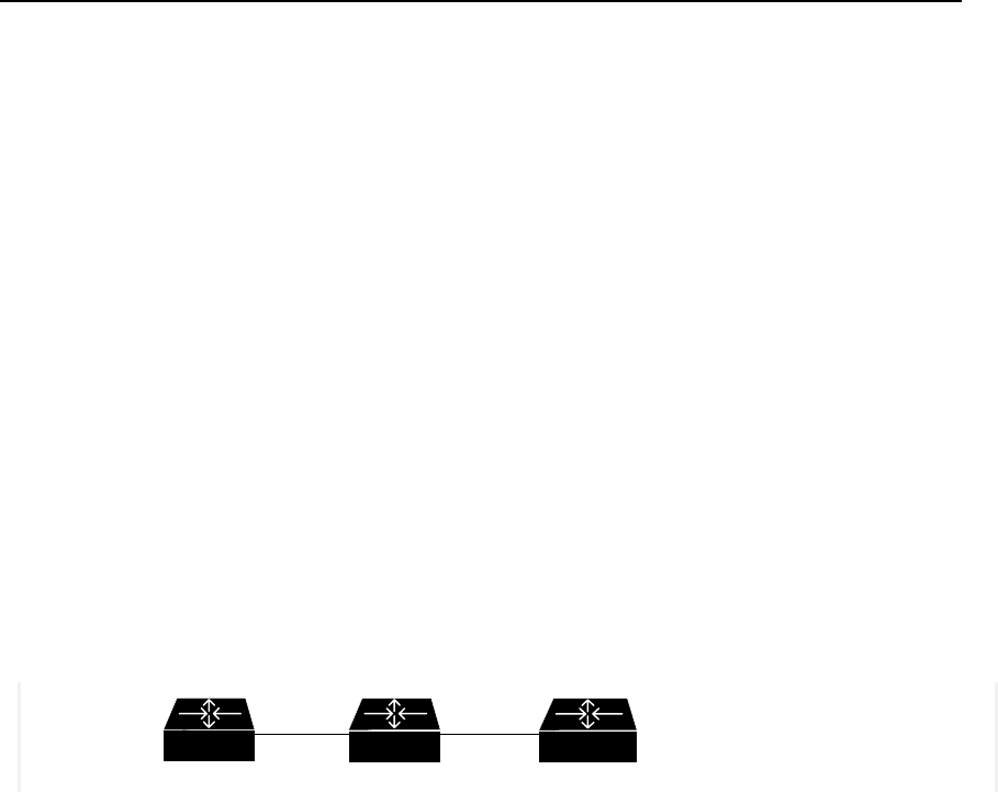
User Manual - Configuration Guide (Volume 3)
Versatile Routing Platform Chapter 2
Traffic Classification and Policing
2-7
Quidway(config-if-Ethernet0)# ip address 190.0.0.1 255.255.255.0
Quidway(config-if-Ethernet0)# rate-limit input 8000 8000 8000 conform transmit
exceed drop
! Apply CAR to all the packets outing Ethernet interface 1 of router A.
Quidway(config-if-Ethernet1)# ip address 191.0.0.1 255.255.255.0
Quidway(config-if-Ethernet1)# rate-limit output 8000 8000 8000 conform transmit
exceed drop
2.3.2 Apply CAR Rules to Packets Which is Matched the ACL
I. Requirements
z Apply CAR to packets entering serial 0 of router A and matching the specified ACL,
forwarding the packets according with the qualification, discarding those
unqualified ones.
z Apply CAR to packets outing serial 0 of router A and matching the specified ACL,
forwarding the packets according with the qualification, discarding those
unqualified ones.
II. Networking diagram
Figure QC-2-3 Networking diagram of apply CAR rules to packets which is matched the ACL
III. Configuration
Configure router A:
! Apply CAR to packets entering serial 0 of router A and matching the specified ACL.
Quidway(config)# access-list 1 permit 10.0.0.2
Quidway(config-if-Serial0)# ip address 10.0.0.1 255.255.255.0
Quidway(config-if-Serial0)# rate-limit input access-group 1 8000 8000 8000 conform
transmit exceed drop
! Apply CAR to packets outing serial 0 of router A and matching the specified ACL.
Quidway(config)# access-list 1 permit 10.0.0.2
Quidway(config-if-Serial0)# ip address 11.0.0.1 255.255.255.0
Quidway(config-if-Serial0)# rate-limit output access-group 1 8000 8000 8000 conform
transmit exceed drop
Router A
Router B
Router C
S0
10.0.0.2
S0
10.0.0.1 S0
11.0.0.2
S1
11.0.0.1
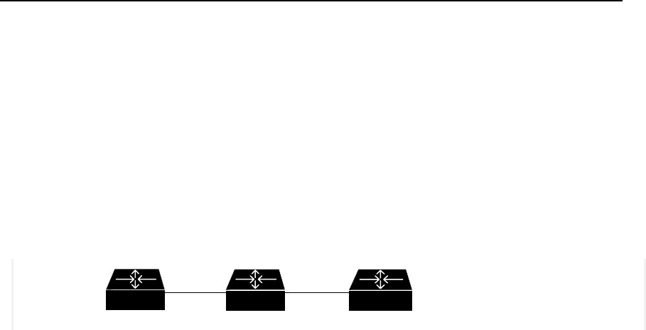
User Manual - Configuration Guide (Volume 3)
Versatile Routing Platform Chapter 2
Traffic Classification and Policing
2-8
2.3.3 Configure CAR Rules Based on the Priority Level
I. Requirements
z Matching CAR based on the priority level to the packets entering serial 0 of router
A, forwarding the packets according with the qualification, discarding those
unqualified ones.
z Matching CAR based on the priority level to the packets outing serial 1 of router A,
forwarding the packets according with the qualification, discarding those
unqualified ones.
II. Netwo rking d iagram
Figure QC-2-4 Networking diagram of configuring CAR rules based on the priority level
III. Configuration
Configure router A:
! Matching CAR based on the priority level to the packets entering serial 0 of router A.
Quidway(config)# rate-limit-list 1 1
Quidway(config-if-Serial0)# ip address 10.0.0.1 255.255.255.0
Quidway(config-if-Serial0)# rate-limit input rate-limit-group 1 8000 8000 8000 conform
transmit exceed drop
! Matching CAR based on the priority level to the packets outing serial 1 of router A.
Quidway(config)# rate-limit-list 1 2
Quidway(config-if-Serial0)# ip address 11.0.0.1 255.255.255.0
Quidway(config-if-Serial0)# rate-limit output rate-limit-group 1 8000 8000 8000
conform transmit exceed drop
2.3.4 Configure CAR Rules Based on the MAC Address
I. Requirements
z Matching CAR based on MAC address to the packets entering serial 0 of router A
(packets from source address 00e0.34b0.7676), modify the priority level value of
the packet according with the qualification into 7, discarding those unqualified
packets.
Router A
Router B
Router C
S0
10.0.0.2
S0
10.0.0.1 S0
11.0.0.2
S1
11.0.0.1

User Manual - Configuration Guide (Volume 3)
Versatile Routing Platform Chapter 2
Traffic Classification and Policing
2-9
II. Networking diagram
Figure QC-2-5 Networking diagram of configuring CAR based on the MAC address
III. Configuration
Configure router A
! Matching CAR based on MAC address to the packets entering serial 0 of router A.
Quidway(config)# rate-limit-list 1 100 00e0.34b0.7676
Quidway(config-if-Serial0)# ip address 10.0.0.1 255.255.255.0
Quidway(config-if-Serial0)# rate-limit input rate-limit-group 1 8000 8000 8000 conform
transmit exceed drop
Router A
Router B
Router C
S0
10.0.0.2
S0
10.0.0.1 S0
11.0.0.2
S1
11.0.0.1
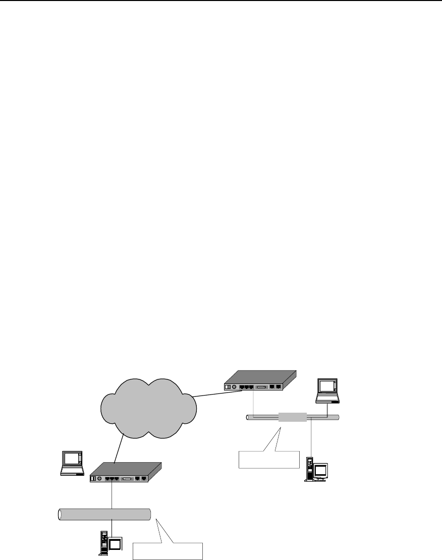
User Manual - Configuration Guide (Volume 3)
Versatile Routing Platform Chapter 3
Congestion Management
3-1
Chapter 3 Congestion Management
3.1 Congestion and Congestion Management
3.1.1 About Congestion
For a network unit, if data packets reach the interface at a speed faster than that the
interface can transmit the data packets, congestion will occur at this interface. And
some packets may be lost if there is no enough space to store them. The loss of data
packets will in turn cause the same host or router to redirect the data packets due to
timeout, as a result, a vicious circle will happen.
There are many factors to cause congestion. For example, if the packet flow enters the
router from a high-speed link and is sent out from a low-speed link, congestion will
occur. And if packet flows enter the router from several interfaces at the same time
while they are sent out from one interface or the processor speed is slow, congestion
will also occur.
As shown in the figure below, two LANs of an enterprise is interconnected through a
low-speed link. When a user in LAN1 sends data packets to a user in LAN 2,
congestion may occur at the interface that connects the router of LAN 1 with the low-
speed link. If an important application is running between the servers of the two LANs,
while an unimportant application is running between the two PCs, the important
application will be affected.
DDN/FR/ISDN/PSTN Quidway router
Ethernet
Server
Ethernet
PC
Server Company’s LAN 1
Company’s LAN 2
Quidway router
PC
10 M
10 M
Congestion occurs
Figure QC-3-1 Example of congested network
3.1.2 Congestion Management Policy
When congestion occurs, some packets may be discarded if there is no enough buffer
to store them. The loss of data packets will in turn cause the same host or router to

User Manual - Configuration Guide (Volume 3)
Versatile Routing Platform Chapter 3
Congestion Management
3-2
resend the data packets due to timeout, and congestion happens again, and then the
packets are sent again, a vicious circle happens. To manage the congestion of network,
people adopt some policies. When congestion occurs, the router can adopt a specific
policy to dispatch the data packets, and decide which packets to be sent with priority,
and which packets to be discarded. The policy adopted by the router to deal with
congestion is called congestion management policy. Usually Queuing technology is
adopted to manage the congestion. When congestion occurs, data packets queue up
at the sending interface of the router following a certain policy. When the packets are
dispatched, the sending sequence of the packets is determined following a certain
policy.
I. FIFO Queuing
In FIFO (First-In First-Out) queuing, communication priority and classification is not
concerned. In FIFO application, the sequence of sending out data packets from the
interface depends on the arriving sequence of the data packets at this interface.
FIFO provides basic capability of storage and forwarding. In some cases, FIFO is the
default queuing algorithm, which should not be modified.
II. PQ (Priority Queuing)
In PQ (Priority Queuing), packets with a specific communication priority will be
forwarded earlier than all other packets with lower priorities, thus ensuring that the
packets with higher priority can be sent out in time.
PQ is used to provide strict priority for important network data. PQ can flexibly specify
priority sequence according to network protocol (IP protocol for example), data inflow
interface, length of the packet, source address/destination address, etc. It ensures that
the most important data in the network unit using PQ can be processed as fast as
possible.
III. CQ (Custom Queuing)
In CQ (Custom Queuing), a specific proportion of the available bandwidth of the
interface is reserved for each specified traffic type. When the reserved bandwidth is not
used by its type of traffic, it can be used by other types of traffic. That is, in CQ mode,
bandwidth is allocated in proportion, and CQ permits to specify the total number of
byte/packet to be extracted from the queue.
For interfaces with a low rate, the data flow passing through this interface can also
receive network service to some extent when the queue is customized for the interface.
IV. WFQ (Weighted Fair Queuing)
WFQ (Weighted Fair Queuing) provides a dynamic and fair queuing mode, in which the
traffic is distinguished based on priority/weight, and according to the different sessions.
The occupation of bandwidth is determined for each session, thus ensuring a fair
treatment to all communications according to their weight. The traffic is classified by
WFQ in the light of source address, destination address, source port number,
destination port number and protocol type, etc.

User Manual - Configuration Guide (Volume 3)
Versatile Routing Platform Chapter 3
Congestion Management
3-3
3.1.3 Selecting Congestion Management Policy
Quidway series routers implement the above four congestion management policies
(FIFO, PQ, CQ and WFQ) at the Ethernet port and serial port (PPP, FR and HDLC
encapsulation), meeting different QoS demands of different services.
FIFO implements non-priority policy of the packets in user data communication. In this
mode, the priority and type of the communication is not necessary to be specified. But
in the application of FIFO policy, some data that run abnormally may consume most of
the available bandwidth, and occupy the full queue, which will lead to delay of the burst
data source and some important communication data being discarded.
PQ provides strict priority. It ensures that a specific type of communication can be sent,
but all other types of packets may be sacrificed at this time. In terms of PQ, a queue
with lower priority is placed in an unfavorable status. Moreover, the packets in the
queues with lower priority may have no chance to be sent out in the worst circumstance
(available bandwidth is limited, and the transmission frequency of the emergent
communications is very high).
CQ ensures all communications to get service of respective levels by allocating
different bandwidths for them. And it determines the queue size by specifying the total
number of packets configured in the queue, so as to control the access to the
bandwidth.
WFQ dynamically divides the communication into packets by fair queuing algorithm.
Packet is one part of the session. WFQ allocates the bandwidths fairly for small-
capacity and interactive communications just as large-capacity communications (for
example, file transmission).
Comparison for these four policies is shown in the table below:

User Manual - Configuration Guide (Volume 3)
Versatile Routing Platform Chapter 3
Congestion Management
3-4
Table QC-3-1 Comparison table of congestion management policies
No. of
queue Advantages Disadvantages
FIFO 1
1.No configuration is needed, and easy
to use.
2. Simple processing with less
processing delay
1. All packets are treated equally, and the
arriving sequence of packets determines the
packet occupied bandwidth, delay and loss of
the packets.
2. It has no restriction on mismatched data
source (for example, UDP packet sending),
while the mismatched data source will affect the
bandwidth of the matched data source (for
example, TCP packet sending).
3. Delay of the real-time application that is
sensitive to time can not be ensured (for
example VoIP).
PQ 4
It provides absolute priority for the data of
different services, and delay is ensured
for real-time applications (for example,
VoIP) that are sensitive to time. The
packet of priority service has absolute
priority to occupy the bandwidth.
1. Configuration is needed, and processing
speed is slow.
2. If the bandwidth for packets with higher priority
is not restricted, packets with lower priority may
not acquire the bandwidth.
CQ 17
1. Bandwidth can be allocated in
proportion for the packets of different
services.
2. If no specific types of packets exist, the
bandwidth can be increased
automatically for the existing packet
types.
Configuration is needed, and processing speed
is slow.
WFQ
Specified
by the use
r
(256 by
default)
1. Easy to configure.
2. The bandwidth can be protected for
coordinated (interactive) data source (for
example, TCP packet sending).
3. Capable of reducing the jitter of the
delay.
4. Small packet is sent with priority.
5. Different bandwidths can be allocated
for the flows with different priorities.
6. When the number of the flows is
reduced, the bandwidths for the existing
traffic can be increased automatically.
The processing speed is slower than FIFO.
3.1.4 Working Principle of Congestion Management Policy
Normally, queuing technology is adopted to manage congestion. When congestion
occurs, data packets queue up at the sending interface of the router following a certain
policy. When the packets are dispatched, the sending sequence of the packets is
determined following a certain policy.
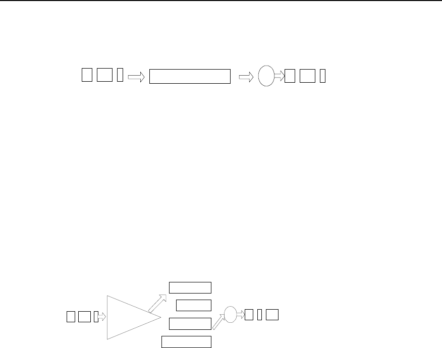
User Manual - Configuration Guide (Volume 3)
Versatile Routing Platform Chapter 3
Congestion Management
3-5
I. FIFO
Dequeuing dispatch
Packets leaving the interface
queue
Packets sent from this interface
Figure QC-3-2 Schematic diagram of FIFO queuing
As shown in the figure above, packets enter FIFO queue in sequence. The dequeuing
sequence is the same as the incoming queue sequence, that is, the packet that arrives
earlier will be sent earlier, while the packet arrives later will be sent later. FIFO does not
make any judgement on the packets, and allocation of network bandwidth and resource
are determined according to the arriving sequence of the packets. Therefore, vicious
application may occupy all network resources, seriously affecting data transmission of
key services.
II. PQ
high
medium
normal
low
Classification Dequeuing dispatch
Packets leaving
the interface
Queue
Packets sent
from this
interface
Figure QC-3-3 Schematic diagram of priority queuing
As shown in the figure above, PQ is used to provide strict priority for important network
data. It ensures that the most important data in the network unit using PQ can be
processed as fast as possible. PQ can flexibly specify the priority sequence according
to network protocol (for example, IP and IPX), data inflow interface, length of the packet
and source address/destination address.
When the queues are dispatched, PQ first sends the packets in the queue with higher
priority in strict compliance with high-to-low sequence. If the queue with higher priority
is empty, the packets in the queue with lower priority can be sent. The packets in the
queue with lower priority might be congested due to the existence of packets in the
queue with higher priority. Therefore, the packets of key service (for example, ERP) are
put in the queue with higher priority, and the packets of ordinary service (for example,
E-mail) are put in the queue with lower priority. In this way, it can be ensured that
packets of key services are transmitted with priority, and the packets of ordinary
services are transmitted in the idle intervals during the processing of the key service
data.

User Manual - Configuration Guide (Volume 3)
Versatile Routing Platform Chapter 3
Congestion Management
3-6
III. CQ
Queue 1
Queue 2
Queue 16
...
C lassificatio n
Dequeuing dispatch
Packets leaving the interface
10%
10%
30%
Queue
Packets sent from this interface
Figure QC-3-4 Schematic diagram of custom queuing
As shown in the figure above, CQ classifies the packets into 17 categories
(corresponding to 17 queues in CQ) following the specified policy. According to its
category, the packets queue up and enter the corresponding queue of CQ based on the
first-in first-out policy. Of the 17 queues of CQ, No.0 queue is a system queue, and
No.1 to No.16 are user queues. And the user can configure the proportion of interface
bandwidth occupied for each user queue. When the queues are dispatched, the
packets in the system queue are sent with priority until the queue is empty. Then
according to the bandwidth configured beforehand, a specific amount of packets in
No.1 to No.16 queues are sent out in the polling mode in sequence.
PQ assigns absolute priority to the packets with higher priority level compared with the
packets with lower priority level. Although this ensures that the key service data can be
transmitted with priority, the packets with lower priority level will all be congested if the
bandwidth is occupied completely for transmitting massive packets with higher priority.
If CQ is adopted, this case can be avoided. There are 17 queues in CQ. The user can
configure the policy of flow classification, and specify the proportion of interface
bandwidths occupied by the 16 user queues. Thus, the packets of different services are
allocated with different bandwidths, ensuring that key services can get more
bandwidths while preventing from no bandwidth available for ordinary services.
In the network diagram shown in figure QC-2-1, suppose the server of LAN 1 sends key
service data to the server of LAN 2, and PC of LAN 1 sends ordinary service data to PC
of LAN 2. The serial port connected with WAN is configured with CQ for congestion
management. Key service data flow between the server enters queue A, and ordinary
service data flow between PCs enters queue B. The proportion of interface bandwidth
occupied by queue A against queue B is configured to 3:1 (for example, queue A in
each dispatching can continuously send 6000 bytes of packets, and queue B in each
dispatching can continuously send 2000 bytes of packets). In this way, CQ treats the
two packet types of different services in different ways. When queue A is dispatched,
the packets is sent continuously till the number of bytes being sent is no less than 6000
or the queue is empty, then CQ turns to dispatching the next user queue. When queue
B is dispatched, the dispatching will not end till the number of bytes being sent
continuously is no less than 2000 or the queue B is empty. In this way, if congestion
occurs and there are always packets in queue A and B to be sent, from the statistics
result it can be seen that the proportion of the bandwidths acquired by the key services
against the bandwidths acquired by the ordinary services is approximately 3:1.
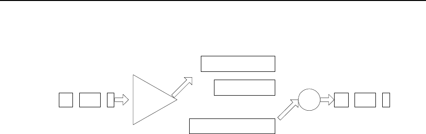
User Manual - Configuration Guide (Volume 3)
Versatile Routing Platform Chapter 3
Congestion Management
3-7
IV. WFQ
queue 1
queue 2
queue N
...
Classification
Dequeuing dispatch
Packets leaving the interface
Queue
Packets sent from
this interface
Figure QC-3-5 Schematic diagram of weighted fair queuing
WFQ embodies the weight on the basis of ensuring fairness, and the amount of the
weight depends on the IP Precedence brought in the IP packet headers. As shown in
the figure above, WFQ classifies the packets according to the flow (packets with the
same source IP address, destination IP address, source port number, destination port
number, protocol number and TOS), and each flow is allocated with to one queue.
When outgoing from the queue, WFQ allocates the bandwidth to be occupied at the exit
by each flow according to the precedence of the flow. The smaller number of the
precedence, the less bandwidth of the flow. The bigger number of the precedence, the
more bandwidth of the flow.
For example, there are currently 8 flows at the interface, with priority of 0, 1, 2, 3, 4, 5, 6
and 7.So, the total bandwidth allocated is the sum of all priorities (flow priority + 1).
That is, 1+2+3+4+5+6+7+8=36
The proportion of bandwidth occupied by each flow is: (priority number +1) / (all
priorities (flow priority + 1)) That is, each flow can acquire the bandwidth as follows:
1/36, 2/36, 3/36, 4/36, 5/36, 6/36, 7/36, 8/36.
Another example: there are 4 flows currently, the priority of three flows is 4, and the
priority of one flow is 5, then the total bandwidth allocated is:
(4 + 1) * 3 + (5 + 1) = 21
Therefore, the bandwidth for the three flows with priority 4 is 5/21, and the bandwidth
for the flow with priority 5 is 6/21.
3.2 Configuration of Congestion Management
3.2.1 Configuring PQ
I. PQ Configuration task list
Configuration task list of priority queue is as follows:
z Configure the priority queue
z Apply priority queue at the interface
z Maintain and monitor the priority queue

User Manual - Configuration Guide (Volume 3)
Versatile Routing Platform Chapter 3
Congestion Management
3-8
II. Configuring priority queue
Priority queue includes the definition for a group of priority queues and it specifies in
which queue a packet is placed and the maximum length of different priority queues.
To complete the queuing of a priority queue, you must allocate this list to the interface.
The same priority queue can be applied to multiple interfaces. Certainly, you can create
multiple different priority policies to be applied to different interfaces.
16 groups can be configured in the priority list at most (that is, the value range of the
list-number is 1-16). In each group, the following information is specified: what kind of
packets enters what kind of queue, length of each queue, the number of the bytes that
can be sent continuously from the respective queues in each polling, etc.
The priority queue can be defined as four levels: high, medium, normal and low.
Packets will be forwarded by the level sequence. That is, after all the packets in the
high queue are sent out, send all the packets in the medium queue, and then send all
the packets in the normal queue, and at last send the packets in the low queue.
Priority queue can be configured according to the modes below.
1) Configure priority queue according to network layer protocols
Data packets can be classified according to different types of protocols to make them
enter different priority queues.
Perform the following task in the global configuration mode.
Table QC-3-2 Configure the priority queue according to the network layer protocol
Operation Command
Configure the priority queue according to the
network layer protocol priority-list list-number protocol protocol-name { high | medium
| normal | low } [ queue-keyword keyword-value ]
Delete classification policy in the priority
queues no priority-list list-number protocol protocol-name { high |
medium | normal | low } [ queue-keyword keyword-value ]
No priority queue is established by default.
Here, list-number is the group number of priority queue. protocol-name is the name of
the protocol, the value of which can be IP and IPX at present.
When protocol-name is IP, the value of queue-keyword and keyword-value is shown in
the table below.
Table QC-3-3 Value of queue-keyword and keyword-value in IP
queue-keyword keyword-value Meaning
Null Null If it is an IP packet, it enters the queue.
fragments Null If it is a fragmentary IP packet, it enters the priority queue
list access-list-number IP packet in compliance with a specific access-list-number (normal)
definition enters the priority queue.
lt Length Value IP packet whose length is smaller than a count value enters the priority
queue.
gt Length Value IP packet whose length is larger than a count value enters the priority queue.
tcp Port No. If the source of IP packet or destination TCP port number is the specified port
number, the packet enters the queue.
udp Port No. If the source of IP packet or destination UDP port number is the specified
port number, the packet enters the priority queue.

User Manual - Configuration Guide (Volume 3)
Versatile Routing Platform Chapter 3
Congestion Management
3-9
If protocol-name is IPX, the value of queue-keyword and keyword-value is shown in the
table below.
Table QC-3-4 Value of queue-keyword and keyword-value in IPX
queue-keyword keyword-value Meaning
Null Null If it is an IPX packet, it enters the queue
lt Length Value IPX packet whose length is smaller than a count value enters the priority
queue.
gt Length Value IPX packet whose length is larger than a count value enters the priority
queue.
2) Configure the priority queue according to the interface
Data packet is classified by the interface through which it enters, and is accordingly put
into queue with different priority.
Perform the following task in the global configuration mode.
Table QC-3-5 Configuring priority queue according to the interface
Operation Command
Configure the priority queue according to
the interfaces priority-list list-number interface type number { high | medium |
normal | low }
Delete classification policies in the priority
queue no priority-list list-number interface type number {high | medium |
normal | low }
No priority queue is established by default.
3) Configure the default queue
Packets not in compliance with any matching policy in the priority queue should be
allocated to a default priority queue.
Perform the following task in the global configuration mode.
Table QC-3-6 Configuration the default priority queue
Operation Command
Configure the default priority queue priority-list list-number default { high | medium | normal | low }
Restore the default priority of the priority
queue no priority-list list-number default
No priority queue is established by default.
Multiple policys can be defined for a group of the priority queue, and this group can be
applied to a certain interface. When a packet reaches this interface (then sent out from
this interface), the system matches this packet along the policy link. If the packet is
matched with a certain policy, it enters the corresponding queue, and the matching is
completed. If the packet does not match with any policy, it enters the default queue.
The default priority of the priority queue is normal.
4) Specify the queue length of the priority queue (optional)
The queue length in each priority queue can be specified (the queue length refers to the
maximum number of packets that can be accommodated in a queue).
Perform the following task in the global configuration mode.

User Manual - Configuration Guide (Volume 3)
Versatile Routing Platform Chapter 3
Congestion Management
3-10
Table QC-3-7 Configuration of queue length of priority queue
Operation Command
Configure the queue length of the priority
queue priority-list list-number queue-limit high-limit medium-limit
normal-limit low-limit
Restore the default value of priority queue
length no priority-list list-number queue-limit
The default length of respective queues is shown in the table below.
Table QC-3-8 The value of default length of the priority queue
Queue Length
high 20
medium 40
normal 60
low 80
III. Applying priority queue to the interface
The configured priority queue can be applied to a specific interface, and each interface
can be allocated only with one priority queue.
Perform the following task in the interface configuration mode.
Table QC-3-9 Apply the priority queue to the interface
Operation Command
Apply the priority queue to the interface priority-group list-number
Restore the default congestion management policy at the interface no priority-group
The interface adopts FIFO queuing by default.
IV. Maintaining and monitoring the priority queue
Table QC-3-10 Maintenance and monitoring of the priority queue
Operation Command
Show the status of the priority queue show queueing priority
Show the configuration of the priority queue at the interface show interface [ type number ]
Enable the priority queue debugging packets switches debug priority-queue
1) Show the status of the priority queue. (If a value is the same with its default value,
the status is not showed).
Quidway# show queueing priority
List Queue Args
1 high 645
1 medium 22
1 normal 123
1 low 567
5 high protocol ip

User Manual - Configuration Guide (Volume 3)
Versatile Routing Platform Chapter 3
Congestion Management
3-11
3.2.2 Configuring CQ
I. CQ configuration task list
Configuration task of custom queuing is as follows:
z Configure the custom queue
z Apply the custom queue to the interface
z Maintenance and monitoring of the custom queue
II. Configuring the custom queue
16 groups can be configured in the custom queue at most (that is, the value range of
the list-number is 1-16). In each group, the following information is specified: what kind
of packets enters what kind of queue, length of each queue, the number of the bytes
that can be sent continuously from the respective queues in each polling, etc. Each
time packets of No.1-16 queues are sent in turn. The number of bytes sent each time
cannot be less than the number defined by the queue, and packets will be sent out until
the queue is empty.
Multiple priority queues can be configured. The system will match the packets
according to the sequence specified in the policy list. If the system finds that the packet
matches with a policy, it ends the whole searching process.
Custom queue can be configured according to the modes below.
1) Configure the custom queue according to the network layer protocol
Packets can be classified according to the different protocol types, and make them
enter the queues with different custom priority.
Perform the following task in the global configuration mode.

User Manual - Configuration Guide (Volume 3)
Versatile Routing Platform Chapter 3
Congestion Management
3-12
Table QC-3-11 Configuring the custom queue according to network layer protocol
Operation Command
Configure the custom queue according to the
network layer protocol custom-list list-number protocol protocol-name queue-
number [ queue-keyword keyword-value ]
Delete the classification policy in the custom queue no custom-list list-number protocol protocol-name
queue-number [ queue-keyword keyword-value ]
Here, list-number is the group number of the custom queue. Queue-number is the
queue number, the value of which can be 0-16. protocol-name can be IP and IPX. The
values of queue-keyword and keyword-value are the same as the values in the priority
queue.
2) Configure the custom queue according to the interface configuration
Packets can be classified according to different types of router interfaces into which the
packet enters, so that the packets can enter different custom-queues.
Perform the following task in the global configuration mode.
Table QC-3-12 Configuring the custom queue according to the interface
Operation Command
Configure the custom queue according to the
interface custom-list list-number interface type number queue-
number
Delete the policy in the custom queue no custom-list list-number interface type number
3) Configure the default queue
Packet not in compliance with any matching policy in the priority queue should be
allocated with a default custom-queue.
Perform the following task in global configuration mode.
Table QC-3-13 Configuration the default custom queue
Operation Command
Configure the default custom queue custom-list list-number default queue-number
Restore the default queue number of the custom queue no custom-list list-number default
Multiple policies can be defined for a custom queue, and these policies can be applied
to a certain interface. When a packet reaches this interface (and sent out from this
interface), the system will match for this packet along the policy link. If the packet is
matched with a specific policy, it enters the corresponding queue, and the matching is
completed. If the packet does not match any policy, it enters the default queue. The
number of the default custom queue is 16 by default.
4) Specify the queue length of the custom queue (optional)
The queue length of each priority queue can be specified (the queue length refers to
the maximum number of packets that can be accommodated in a queue).
Perform the following task in the global configuration mode.

User Manual - Configuration Guide (Volume 3)
Versatile Routing Platform Chapter 3
Congestion Management
3-13
Table QC-3-14 Configuration of queue length of the custom queue
Operation Command
Configure the queue length of the custom
queue custom-list list-number queue queue-number limit queue-limit
Restore the default value of custom queue
length no custom-list list-number queue queue-number limit
The queue length of the custom queue is 20 by default, with the value range of 0-32767
packets.
5) Configure the continuously sent byte number of the custom queue (optional),
The continuously sent byte number can be specified for each custom queue (the
number of bytes that can be accommodated).
Perform the following task in the global configuration mode.
Table QC-3-15 Configure the continuously sent byte number of the custom queue
Operation Command
Configure the continuously sent byte number of
the custom queue custom-list list-number queue queue-number byte-count
byte-count-number
Restore the default value of the continuously
sent byte number of the custom queue no custom-list list-number queue queue-number byte-count
By default the continuously sent byte number of each queue is 1500 in each polling and
the value range is 0-16777215 bytes.
byte-count-number: when the router dispatches the user queue of CQ, it keeps taking
out packets from this queue to send till the sent byte count is no less than the value of
byte-count-number configured for this queue or until this queue is empty, then it turns to
dispatch the next user queue of CQ. Therefore, the value of byte-count-number will
affect the proportion of interface bandwidth occupied by each user queue of CQ, and
determine the duration after which the router will dispatch the next queue of CQ.
If the value of byte-count-number is too small, since the router will turn to the next
queue only after it has at least sent one packet, the bandwidth actually obtained by
respective queues may be quite different from what is expected. If the value of byte-
count-number is too big, long delay may be resulted from switching between the
queues.
III. Applying custom queue to the interface
The configured custom queue can be applied to a specific interface, and each interface
can only be allocated with one custom queue.
Perform the following task in the interface configuration mode.
Table QC-3-16 Apply the custom queue to the interface
Operation Command
Apply the custom queue to the interface custom-group list-number
Restore the default congestion management policy at the interface no custom-group

User Manual - Configuration Guide (Volume 3)
Versatile Routing Platform Chapter 3
Congestion Management
3-14
The interface adopts FIFO queuing by default.
IV. Maintaining and monitoring the custom queue
Table QC-3-17 Maintenance and monitoring of the custom queue
Operation Command
Show the custom queue status show queuing custom
Show the configuration of the custom queue at the interface show interface [type number]
Enable the custom queue debugging packets switches debug custom-queue
6) Show the status of the custom queue.
Quidway# show queueing custom
Current custom-queue-list configuration:
List Queue Args
1 0 default
3.2.3 Configuring WFQ
I. WFQ configuration task list
Configuration task of weighted fair queue is as follows:
z Configure the weighted fair queue
z Maintenance and monitoring of the weighted fair queue
II. Configuring the weighted fair queue
Perform the following task in the interface configuration mode.
Table QC-3-18 Configuring the weighted fair queue
Operation Command
Configure the weighted fair queue fair-queue [ discard-threshold [ dynamic-queue-count ] ]
Restore the managing policy of the default queue
congestion on the interface no fair-queue
By default, FIFO is adopted as the congestion management policy. discard-threshold is
64 bytes and dynamic-queue-count is 256 bytes by default.
III. Maintenance and monitoring of the weighted fair queue
Table QC-3-19 Maintenance and monitoring of the weighted fair queue
Operation Command
Show the configuration of the weighted fair queue show queueing fair
Enable the fair queue debugging packets switches debug fair-queue
1) Show the status of the weighted fair queue.
Quidway# show queueing fair
Current fair queue configuration:
Interface Discard threshold Dynamic queue count

User Manual - Configuration Guide (Volume 3)
Versatile Routing Platform Chapter 3
Congestion Management
3-15
Serial0 64 256
3.3 Configuration Example of Congestion Management
3.3.1 PQ Configuration Example
! Define access control list, permitting packets from network segment 10.10.0.0 to
pass.
Quidway(config)# access-list 1 permit 10.10.0.0
! Define a policy for the 1st group of the priority queue, allow IP packet with access-
list-list 100 to enter the queue with high priority.
Quidway(config)# priority-list 1 protocol ip high list 1
! Define the length of the 1st high queue of the priority queue as 10, and the lengths of
other queues adopt default values.
Quidway(config)# priority-list 10 queue-limit 10 40 60 80
! Apply priority queue 1 on Serial 0.
Quidway(config-if-Serial0)# priority-group 1
! Define a policy for the 2nd group of the priority queue, making all the packets from
Serial 1 enter the queue with medium priority.
Quidway(config)# priority-list 2 interface serial 1 medium
! Apply priority queue 2 on Serial 1.
Quidway(config-if-Serial0)# priority-group 2
3.3.2 CQ Configuration Example
I. Requirements
In WAN, establish two parallel tunnels (GRE encapsulation) that correspond the same
physical line, requiring that the physical line bandwidths are proportionally allocated
according to the services on the two tunnels.
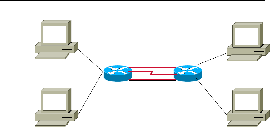
User Manual - Configuration Guide (Volume 3)
Versatile Routing Platform Chapter 3
Congestion Management
3-16
II. Networking diagram
PC1:10.1.3.10
PC3:10.1.4.10
PC2:10.1.5.10
PC4:10.1.6.10
e0:10.1.5.1
e1:10.1.6.1
e0.0:10.1.3.1
e0.1:10.1.4.1 s0:192.168.0.1
s0:192.168.0.2
(10.1.1.1)tunnel0(10.1.1.2)
(10.1.7.1)tunnel1(10.1.7.2)
8240 3680
Figre QC-3-6 Networking diagram of CQ Configuration
III. Configuration
1) Configuring 8240 router
! Configure access control list
Quidway(config)# access-list normal 105 permit ip 10.1.5.0 0.0.0.255 10.1.4.0
0.0.0.255
Quidway(config)# access-list normal 105 deny ip any any
Quidway(config)# access-list normal 107 permit ip 192.168.0.1 0.0.0.0 192.168.0.2
0.0.0.0
Quidway(config)# access-list normal 108 permit ip 192.168.1.1 0.0.0.0 192.168.1.2
0.0.0.0 (CQ uses this command)
! Configure CQ
Quidway(config)# custom-list 1 queue 1 limit 100
Quidway(config)# custom-list 1 queue 1 byte-count 5000
Quidway(config)# custom-list 1 queue 2 limit 100
Quidway(config)# custom-list 1 queue 2 byte-count 1000
Quidway(config)# custom-list 1 protocol ip 1 list 107
Quidway(config)# custom-list 1 protocol ip 2 list 108 (CQ restricts that the flow of
tunnel0 is larger than that of tunnel1, and CQ is effective at the exit)
! Configure main and slave address of Serial0
Quidway(config-if-Serial0)# ip address 192.168.0.2 255.255.255.252
Quidway(config-if-Serial0)# ip address 192.168.1.2 255.255.255.252 secondary
! Apply CQ 1 on Serial0
Quidway(config-if-Serial0)# custom-group 1

User Manual - Configuration Guide (Volume 3)
Versatile Routing Platform Chapter 3
Congestion Management
3-17
! Configure Tunnel0
Quidway(config-if-Tunnel0)# ip address 10.1.2.1 255.255.255.0
Quidway(config-if-Tunnel0)# tunnel source 192.168.0.2
Quidway(config-if-Tunnel0)# tunnel destination 192.168.0.1
! Configure Tunnel1
Quidway(config-if-Tunnel1)# ip address 10.1.7.1 255.255.255.0
Quidway(config-if-Tunnel1)# tunnel source 192.168.1.2
Quidway(config-if-Tunnel1)# tunnel destination 192.168.1.1
2) Configuring 3680 router
Quidway(config)# access-list normal 105 permit ip 10.1.4.0 0.0.0.255 10.1.5.0
0.0.0.255
Quidway(config)# access-list normal 105 deny ip any any
Quidway(config)# access-list normal 107 permit ip 192.168.0.2 0.0.0.0 192.168.0.1
0.0.0.0
Quidway(config)# access-list normal 108 permit ip 192.168.1.2 0.0.0.0 192.168.1.1
0.0.0.0 (CQ uses this command)
! Configure CQ
Quidway(config)# custom-list 1 queue 1 limit 100
Quidway(config)# custom-list 1 queue 1 byte-count 5000
Quidway(config)# custom-list 1 queue 2 limit 100
Quidway(config)# custom-list 1 queue 2 byte-count 1000
Quidway(config)# custom-list 1 protocol ip 1 list 107
Quidway(config)# custom-list 1 protocol ip 2 list 108 (CQ restricts that the flow of
tunnel0 is larger than that of tunnel1, and CQ is effective at the exit)
! Configure main and slave address of Serial0
Quidway(config-if-Serial0)# ip address 192.168.0.1 255.255.255.252
Quidway(config-if-Serial0)# ip address 192.168.1.1 255.255.255.252 secondary
! Apply CQ 1 on Serial0
Quidway(config-if-Serial0)# custom-group 1
! Configure Tunnel0
Quidway(config-if-Tunnel0)# ip address 10.1.2.2 255.255.255.0
Quidway(config-if-Tunnel0)# tunnel source 192.168.0.1
Quidway(config-if-Tunnel0)# tunnel destination 192.168.0.2
! Configure Tunnel1
Quidway(config-if-Tunnel1)# ip address 10.1.7.2 255.255.255.0
Quidway(config-if-Tunnel1)# tunnel source 192.168.1.1

User Manual - Configuration Guide (Volume 3)
Versatile Routing Platform Chapter 3
Congestion Management
3-18
Quidway(config-if-Tunnel1)# tunnel destination 192.168.1.2
3.4 Troubleshooting of Congestion Management
The common fault of congestion management configuration is that the expected goal of
the user can not be fulfilled when the configuration is completed. The fault is usually
caused by the incorrect policy of flow classification configured by the user. To solve the
problem, enable the information debugging and locate the fault according to the
debugging information displayed on the screen.
z Display PQ debugging information
Quidway#debug priority-queue
Quidway(config)#logging on
Quidway(config)#log console debug
When packets are sent by the interface configured with PQ policy, all information about
queue selection will be shown on the screen.
z Display CQ debugging information
Quidway# debug custom-queue
Quidway(config)# logging on
Quidway(config)#log console debug
When packets are sent by the interface configured with CQ policy, all information about
queue selection will be shown on the screen.
z Display WFQ debugging information
Quidway# debug fair-queue
Quidway(config)# logging on
Quidway(config)# logging console debug
When packets are sent by the interface configured with WFQ policy, all information
about queue selection will be shown on the screen.
HUAWEI®
VRP
User Manual – Configuration Guide
Volume 3
10 – DDR Configuration (DC)

User Manual -Configuration Guide (Volume 3)
Versatile Routing Platform Table of Contents
i
Table of Contents
Chapter 1 DDR Configuration ..................................................................................................... 1-1
1.1 Brief Introduction to Dial Configuration............................................................................. 1-1
1.2 Introduction to DDR Technology....................................................................................... 1-1
1.3 Preparing DDR Configuration ........................................................................................... 1-2
1.4 Configuring DDR............................................................................................................... 1-3
1.4.1 Configuring Legacy DDR ....................................................................................... 1-3
1.4.2 Configuring Dialer Profile ..................................................................................... 1-11
1.4.3 Configuring Callback ............................................................................................ 1-13
1.4.4 Configuring DDR Special Functions .................................................................... 1-18
1.5 Monitoring and Maintenance of DDR.............................................................................. 1-20
1.6 DDR Typical Configuration Example .............................................................................. 1-21
1.6.1 Legacy DDR ......................................................................................................... 1-21
1.6.2 Dialer Profile......................................................................................................... 1-23
1.6.3 Point-to-Point DDR............................................................................................... 1-25
1.6.4 Point-to-Multipoint DDR ....................................................................................... 1-28
1.6.5 Multipoint-to-Multipoint DDR ................................................................................ 1-31
1.6.6 DDR Bearing IPX ................................................................................................. 1-37
1.6.7 DDR Bearing IP and IPX at the Same Time ........................................................ 1-41
1.6.8 Flow Control of Dialer Profile (MP over Dialer Profile)-Case 1 ............................ 1-45
1.6.9 B Channels for Dial-up and Connection to the Remote End - Case 2................. 1-47
1.6.10 Two Serial Ports for Dial-up and Remote Dial Connection – Case 3 ................ 1-49
1.6.11 One Serial Port for Dial-up and Remote Dial Connection – Case 4 .................. 1-50
1.6.12 DDR for Access Service..................................................................................... 1-52
1.6.13 DDR for Inter-Router Callback ........................................................................... 1-57
1.6.14 DDR in Which the Router Calls Back PC........................................................... 1-59
1.6.15 DDR for Autodial ................................................................................................ 1-61
1.6.16 DDR Using Dialer Map Cyclically....................................................................... 1-62
1.6.17 DDR Using Dialer Map as Backup..................................................................... 1-63
1.7 Precautions for DDR Configuration ................................................................................ 1-65
1.7.1 Configuring Dialer-group ...................................................................................... 1-65
1.7.2 Configuring Synchronous/Asynchronous Serial Port Using DDR........................ 1-65
1.7.3 Configuring Network Layer Address .................................................................... 1-66
1.7.4 Configuring PPP In Dialer Profile Configuration Mode ........................................ 1-67
1.7.5 Configuring PPP In Legacy DDR Configuration Mode......................................... 1-71
1.7.6 Configure Dialer-list.............................................................................................. 1-75

User Manual -Configuration Guide (Volume 3)
Versatile Routing Platform Table of Contents
ii
1.8 Troubleshooting DDR ..................................................................................................... 1-75
1.8.1 DDR Fault Diagnosis............................................................................................ 1-75
1.8.2 DDR Fault Elimination.......................................................................................... 1-79
1.8.3 Troubleshooting with DDR Debugging Information.............................................. 1-80
Chapter 2 Configuration of Modem Management ..................................................................... 2-1
2.1 Modem Management Functions Provided by VRP1.4...................................................... 2-1
2.2 Modem Script.................................................................................................................... 2-1
2.2.1 Function.................................................................................................................. 2-1
2.2.2 Syntax .................................................................................................................... 2-1
2.3 Configuring Modem Management .................................................................................... 2-3
2.3.1 Modem Management Configuration Task List ....................................................... 2-3
2.3.2 Configuring Modem Call-In and Call-Out Authorities ............................................. 2-3
2.3.3 Configuring Modem Script...................................................................................... 2-3
2.3.4 Executing Modem Script Manually......................................................................... 2-4
2.3.5 Specifying the Event to Trigger Modem Script....................................................... 2-4
2.3.6 Configuring Modem Answer Mode......................................................................... 2-4
2.4 Typical Configuration of Modem Management................................................................. 2-5
2.4.1 Managing Modem with Modem Script.................................................................... 2-5
2.4.2 Remote Configuration Using Modem and Through Asynchronous Interface ........ 2-6
2.4.3 Router Initialization with Initialization Script ........................................................... 2-7
2.4.4 Direct Dial with Script ............................................................................................. 2-7
2.4.5 Interactively Connect Cisco Router Through Modem ............................................ 2-8

User Manual - Configuration Guide (Volume 3)
Versatile Routing Platform Chapter 1
DDR Configuration
1-1
Chapter 1 DDR Configuration
1.1 Brief Introduction to Dial Configuration
VRP1.3 provides subscribers with a perfect dial solution:
z Support various dial interfaces, including asynchronous serial ports, ISDN BRI
interface and ISDN PRI interface, for subscribers to choose from according to
networking needs and network conditions.
z Provide powerful DDR (Dial-on-Demand Routing) function to meet the needs of
subscribers for various network topologies.
z Support link layer protocols like PPP.
z Support network layer protocols like IP and IPX.
z Support to run dynamic routing protocols like RIP on dial interfaces.
z Support flexible dial interface backup modes.
z Provide, at asynchronous dial interfaces, powerful control on various Modems.
z Highly interoperable with the dial functions of other various routers of the industry.
The following are the meanings of terms used in this chapter.
z Physical interface: interface that physically exists, like Serial0 interface or Bri0
interface.
z Dialer interface: logical interface that is set for DDR configuration. Specific
physical interfaces can be bound to Dialer interface to enable DDR.
z Dial interface: a generic term for any interface used for dial connection—possibly a
logical Dialer interface, or a physical interface bound to the Dialer interface, or a
physical interface that directly enables DDR.
z Dial string: PSTN telephone number or ISDN telephone number
z Legacy DDR (Legacy DDR): a DDR configuration mode as compared with the
“Dialer Profile”.
z Dialer Profile (Dialer Profiles): developed to meet the needs of various dial
configurations for some common physical interfaces.
1.2 Introduction to DDR Technology
DDR is short for Dial-on-Demand Routing, referring to the routing technique used for
interconnection of routers through PSTN. Currently there are two major kinds of public
switched networks, PSTN (public switched telephone network) and ISDN (integrated
services digital network). Dialing is necessary to get connected to them.
DDR is adopted when routers are interconnected by asynchronous serial ports through
PSTN, or by ISDN BRI/PRI interface through ISDN. In most cases, routers are not
connected. Only if there are packets to be transferred between them, will DDR be
started and dialup connection established between them to transfer packets. When the
links are idle, DDR will automatically disconnect them— in other words, “dial-on-
demand”.
Therefore, DDR is quite cost-effective when there is not much information between two
points and, if any, it is transferred in burst mode.
DDR is not a protocol, hence no international standards. It is implemented by various
router vendors themselves as needed.
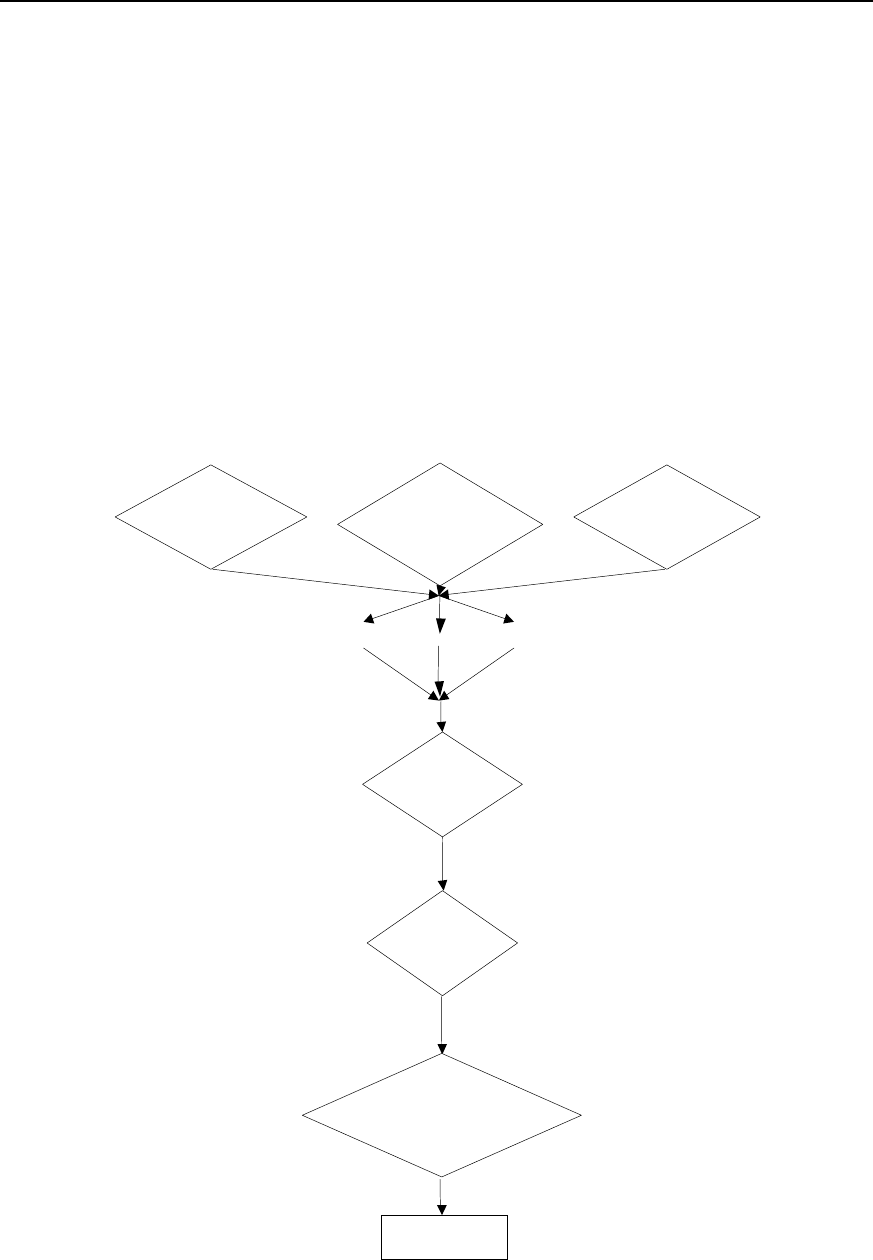
User Manual - Configuration Guide (Volume 3)
Versatile Routing Platform Chapter 1
DDR Configuration
1-2
1.3 Preparing DDR Configuration
For a network needing DDR, subscribers can make configuration preparations
following the flow below.
z Specify which routers in the network need DDR, which interfaces of these routers
use DDR, what transmission medium is used, what topology is adopted, whether
these interfaces are sending calls, receiving calls, or sending and receiving calls at
the same time.
z Specify the type of interface to be used (asynchronous serial port or ISDN BRI/PRI
interface).
z Specify the interface encapsulation to be used (PPP etc.).
z Specify the network protocol to be used (IP or IPX etc.).
z Specify the dynamic routing protocol (RIP etc.) to be used at DDR interface.
z Select either Legacy DDR or Dialer Profile to configure DDR.
z Configure DDR.
The flow chart of configuration preparations is shown in the following figure.
Used by which routers
in the network Which routers send
calls and which
receive
Which network
is used (PSTN or ISDN)
Async ISDN
Network protocol?
(IP, IPX)
Encapsulate?
(X.25,FR,SLIP
,PPP)
DDR
Standard DDR (legacy
DDR) or flexible DDR
(Diaber Profiles)
Configure DDR
Serial
Figure DC-1-1 DDR configuration preparation flow

User Manual - Configuration Guide (Volume 3)
Versatile Routing Platform Chapter 1
DDR Configuration
1-3
For details about the configurations of link layer protocol, network layer protocol and
dynamic routing protocol, please refer to “WAN Protocol Configuration”, “Network
Protocol Configuration” and “Routing Protocol Configuration” of this manual.
1.4 Configuring DDR
VRP1.3 provides two DDR configuration modes: Legacy DDR and Dialer Profile. The
differences between the two DDRs are given below:
z Different scopes of applications
As described above, Dialer Profile is developed to meet the needs of various dial
configurations for some common physical interfaces. For example, with only one ISDN
BRI interface, Legacy DDR cannot enable Internet access and interconnection with
another remote terminal at the same time, but this is possible with Dialer Profile.
z Different application methods and configurations
For Legacy DDR, a dial interface may be served by multiple physical interfaces, but a
physical interface can belong to only one dial interface. A physical interface inherits the
attributes of the dial interface that it serves. A physical interface can be both bound to
the dial interface and configured as a dial interface, or directly configured as a dial
interface (which is later referred to as “a physical interface directly enables DDR”).
Finally, a dial interface can correspond to multiple call destination addresses through
dialer map.
For Dialer Profile, although any interface may be served by multiple physical interfaces,
a physical interface may serve multiple dial interfaces at the same time. It is necessary
to configure authentication on the physical interface that serves Dialer Profile so that it
can find, through the subscriber name of the dial-in party, the dial interface it should
serve in this call. A physical interface must be bound to the dial interface to implement
dial function. Finally, a dial interface corresponds to only one call destination address
designated by the command dialer string.
By default, dialer in-band command is configured on ISDN BRI and PRI interfaces.
That is, ISDN BRI/PRI interface is designated by default to enable DDR in Legacy DDR
mode. Therefore:
z If ISDN BRI/PRI interface is configured in Legacy DDR mode, it is unnecessary to
execute dialer in-band command.
z If ISDN BRI/PRI interface is configured in Dialer Profile mode, it is necessary to
execute no dialer in-band command first.
Described below are the configurations of Legacy DDR, Dialer Profile, callback and
special functions.
1.4.1 Configuring Legacy DDR
I. The configuration tasks of Legacy DDR include:
z Configure an interface to send calls
z Configure an interface to receive calls
z Configure an interface to send and receive calls
z Set the attribute parameters of Legacy DDR.
II. Configure an interface to send calls
1) Call to a single point
Step 1: enable DDR.

User Manual - Configuration Guide (Volume 3)
Versatile Routing Platform Chapter 1
DDR Configuration
1-4
Please use the following commands in the configuration mode of the designated
physical interface.
Table DC-1-1 Enable DDR in Legacy DDR mode
Operation Command
Enable DDR in Legacy DDR mode dialer in-band
This command is needed to make a call through an asynchronous serial port. For ISDN
interface, the system automatically loads this command, making manual configuration
with this command unnecessary.
Step 2: set the dial string of the interface.
The following command is needed to call only one destination through this interface.
Please use the following command in the configuration mode of the physical interface
that directly enables DDR.
Table DC-1-2 Set the dial string of the interface
Operation Command
Set the dial string of the interface dialer string dial-string [:isdn-address]
2) Call to multiple points
Step 1: enable DDR.
For configuration mode and command format, please refer to Step 1 of “Call to a single
point”.
Step 2: set different dial strings for different destinations.
Please use the following command in the configuration mode of the physical interface
that directly enables DDR.
Table DC-1-3 Set different dial strings for different destinations
Operation Command
Set different dial strings for different destinations dialer map protocol next-hop-address dialstring [:
isdnsubaddress]
Can define different identifiers for ISDN interface dialer map protocol next-hop-address dialstring [:
isdnsubaddress]
3) Call from Dialer Rotary Group
Dialer Rotary Group matches a logic dial interface to a group of physical interfaces. The
configurations for this logic dial interface will be inherited by the physical interfaces in
the Dialer Rotary Group. When a logic dial interface has been configured, once a
physical interface is put in Dialer Rotary Group, this physical interface will inherit all
configurations for the logic dial interface.
When Dialer Rotary Group has been configured, if multiple destinations have been set
for a logic dial interface, then any physical interface in Dialer Rotary Group can be used
to call any previously set destination.
Dialer Rotary Group applies to the interfaces with multiple calls to multiple destinations.

User Manual - Configuration Guide (Volume 3)
Versatile Routing Platform Chapter 1
DDR Configuration
1-5
To configure a Dialer Rotary Group, follow the steps below:
Step 1: create a logic dial interface.
Please use the following command in global configuration mode.
Table DC-1-4 Create a logic dial interface
Operation Command
Create a logic dial interface interface dialer number
In the command, number is both the interface number of the logic dial interface and the
identification number of Dialer Rotary Group. That is to say, when a logic dial interface
is created, a Dialer Rotary Group is also specified for this interface.
Step 2: enable DDR.
Please use this command in the configuration mode of the logic dial interface.
For the command format, please refer to Step 1 of “Call to a single point”.
Step 3: designate multiple destinations for this Dialer Rotary Group.
Please use this command in the configuration mode of the dial interface.
Table DC-1-5 Set different dial strings for different destinations
Operation Command
Set different dial strings for different
destinations dialer map protocol next-hop-address Dialstring [:
isdnsubaddress]
Step 4: put the physical interface into Dialer Rotary Group.
Table DC-1-6 Put the designated physical interface into Dialer Rotary Group.
Operation Command
Enter the configuration mode of the designated physical interface
(used in global configuration mode) interface interface-type interface-number
Put the physical interface into Dialer Rotary Group (used in the
configuration mode of the designated physical interface) dialer rotary-group number
The physical interface in Dialer Rotary Group doesn’t use its own IP address—in
application, it will inherit the IP address of the logic dial interface. The parameter
number in the command dialer rotary-group number in the configuration mode of the
physical interface should be the same as the number in the command interface dialer
number in the configuration mode of the logic interface corresponding to the physical
interface.
In addition, an ISDN interface (BRI or PRI) itself can be regarded as Dialer Rotary
Group of its subordinate B channel. Meanwhile, it can serve as a physical interface in
other Dialer Rotary Groups.
Following is the schematic diagram of Dialer Rotary Group.
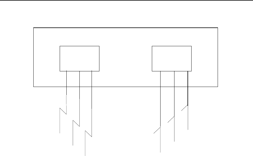
User Manual - Configuration Guide (Volume 3)
Versatile Routing Platform Chapter 1
DDR Configuration
1-6
Dialer
Interface 1
Dialer
Interface 2
Router
Serial 1
Serial 2 Serial 4
Serial 3
Serial 5
Serial 6
Figure DC-1-2 Schematic diagram of Dialer Rotary Group
III. Configure an interface to receive calls
1) Receive calls from a single point
To configure an interface to receive calls from a single point, just enable DDR.
For configuration mode and command format, please refer to Step 1 of “Call to a single
point”.
As described above, for ISDN BRI/PRI interface, Legacy DDR has been enabled by
default, making execution of this command unnecessary.
2) Receive calls from multiple points
Usually, Dialer Rotary Group can be defined to receive calls from multiple points. Calls
can be received flexibly from Dialer Rotary Group.
Step 1: create a logic dial interface.
For configuration mode and command format, please refer to Step 2 of “Call from Dialer
Rotary Group”.
Step 2: enable DDR.
For configuration mode and command format, please refer to Step 2 of “Call from Dialer
Rotary Group”.
Step 3: select PPP encapsulation and select CHAP or PAP authentication.
Receiving calls from multiple points entails CHAP or PAP authentication, otherwise
various points cannot be distinguished from each other. CHAP authentication is
recommended because it has encrypted password before transferring it, while PAP
authentication transfers clear text.
Please use this command in the configuration mode of the logic dial interface.

User Manual - Configuration Guide (Volume 3)
Versatile Routing Platform Chapter 1
DDR Configuration
1-7
Table DC-1-7 Select PPP encapsulation and select CHAP or PAP authentication
Operation Command
Select PPP encapsulation encapsulation ppp
Select authentication mode ppp authentication {chap | pap}
Step 4: set the correspondence between remote call subscriber name and protocol
address so that the router can distinguish them.
Please use the following command in the configuration mode of the logic dial interface.
Table DC-1-8 Set the correspondence between remote subscriber name and protocol address
Operation Command
Set the correspondence between remote subscriber
name and protocol address dialer map protocol next-hop-address name hostname
Step 5: if CHAP authentication is selected, users need to set the correspondence
between user name and password. The settings of both parties of the call shall be
consistent.
Please use the following command in the global configuration mode.
Table DC-1-9 Set the correspondence between user name and password
Operation Command
Set the correspondence between user name and password user name password {0 | 7} password
Step 6: put the physical interface into Dialer Rotary Group.
For the configuration mode, command format and use mode, please refer to Step 4 of
“Call from Dialer Rotary Group”.
IV. Configure an interface to send and receive calls
1) Send calls to and receive calls from a point
To send calls to and receive calls from a point, just make the following configurations
and select PPP encapsulation. It is unnecessary to select authentication mode.
Table DC-1-10 Configure a point to send and receive calls
Operation Command
Enter the configuration mode of a specified physical interface
(used in global configuration mode) interface interface-type interface-number
Enable DDR in Legacy DDR (used in the configuration mode
of a specified physical interface) dialer in-band
Set dial string (used in the configuration mode of the physical
interface that directly enables DDR) dialer string dial-string [: isdnsubaddress]
2) Send calls to and receive calls from multiple points
To send calls to and receive calls from multiple points, make the following
configurations.

User Manual - Configuration Guide (Volume 3)
Versatile Routing Platform Chapter 1
DDR Configuration
1-8
Table DC-1-11 Configure to send calls to and receive calls from multiple points
Operation Command
Enter the configuration mode of a specified physical interface
(used in global configuration mode) interface interface-type interface-number
Select PPP encapsulation (used in the configuration mode of
the specified physical interface) encapsulation ppp
Select authentication mode (used in the configuration mode of
the specified physical interface) ppp authentication {chap | pap}
Configure the correspondence between the protocol address
of the remote interface and user name and dial string (used in
the configuration mode of the specified physical interface)
dialer map protocol next-hop-address name
hostname dialerstring [: isdnsubaddress]
V. Set the attribute parameters of Legacy DDR
1) Set link idle time
If an interface has been set to send calls, then it is possible to set that DDR will
disconnect the link in case of link idle timeout.
Please use the following command in the configuration mode of dial interfaces
(including logic dial interface and physical interface that directly enables DDR, same
below).
Table DC-1-12 Set link idle timeout
Operation Command
Set link idle timeout dialer idle-timeout seconds
2) Set idle time of busy interface
When links compete with each other, fast-idle timer will be started. Competition refers
to the case when an interface, which has already established a link, is required to
establish a new link with another interface. If the idle time of the first link exceeds the
time set by fast-idle timer, DDR will disconnect the first link and establish a new link.
Please use the following command in the configuration mode of the dial interface.

User Manual - Configuration Guide (Volume 3)
Versatile Routing Platform Chapter 1
DDR Configuration
1-9
Table DC-1-13 Set the idle time of busy interface
Operation Command
Set the idle time of busy interface dialer fast-idle seconds
3) Set link disconnection time
When a link is disconnected due to failure or onhook, a new connection can be
established only after the set time.
Please use the following command in the configuration mode of the dial interface.
Table DC-1-14 Set link disconnection time
Operation Command
Set link disconnection time dialer enable-timeout seconds
4) Set the maximum waiting time interval from call originating to call connection
establishment.
Please use the following command in the configuration mode of the dial interface.
Table DC-1-15 Set wait-for-carrier time for port data
Operation Command
Set the maximum waiting time interval from call originating to
call connection establishment. dialer wait-for-carrier-time seconds
5) Set access control of the dial interface
Message filtering function can be set for the dial interface. Messages passing the dial
interface can be classified into two categories through access control:
z Interesting—messages undergoing access control. When the dial interface
receives an interesting message, if the corresponding link has been established,
then DDR will send the message through this link and clear idle-time timer. If the
corresponding link has not been established, then a call will be sent.
z Uninteresting—messages not under access control. When the dial interface
receives an uninteresting message, if the corresponding link has been established,
DDR will send the message through this link and do not clear idle-time timer. If the
corresponding link has not been established, no call will be sent and this message
will be discarded.
If no dialer-group has been configured in the interface configuration, or no dialer-list
corresponding to dialer-group has been configured in the global configuration, the dial
interface cannot send the message.

User Manual - Configuration Guide (Volume 3)
Versatile Routing Platform Chapter 1
DDR Configuration
1-10
Table DC-1-16 Set access control of the dial interface
Operation Command
Configure standard access control list (used in global
configuration mode) access-list access-list-number {deny | permit}
[wildcard-mask]
Configure extended access control list (used in global
configuration mode) access-list access-list-number {deny | permit}
protocol
Configure the correspondence between access-list and
Dialer Access Group (used in global configuration mode)
dialer-list dialer-group protocol protocol-name
{permit | deny}
or dialer-list dialer-group list access-list-number
In the configuration of dial interface, put the interface in
Dialer Access Group (used in the configuration mode of dial
interface) dialer-group group-number
6) Set the priorities of physical interfaces in Dialer Rotary Group
Specify the sequence to use various interfaces based on their priorities.
Please use the following command in the configuration mode of the designated
physical interface.
Table DC-1-17 Set the priorities of physical interfaces in Dialer Rotary Group
Operation Command
Set the priorities of physical interfaces in Dialer Rotary Group dialer priority number
The value range of number is 1-127, 1 being the highest, 127 the lowest, and 1 by
default.
7) Set hold-queue
If no hold-queue has been established at the dial interface, when a message reaches
the dial interface, the message will be lost. If a hold-queue has been established, then
the message will be cached rather than get lost before connection establishment.
Please use the following command in the configuration mode of the dial interface.
Table DC-1-18 Set hold-queue at the dial interface
Operation Command
Set hold-queue at the dial interface dialer hold-queue packets
8) Set load threshold
In a Dialer Rotary Group, when the proportion between flow and bandwidth, which
locate on a physical interface that directly enables DDR (including serial port, ISDN
BRI/PRI interface) or a Dialer interface, exceeds load threshold presupposed, DDR will
start another physical interface or another physical interface belongs to the same Dialer
Rotary Group and transfer data to the same destination. Actually, it realizes dynamic
PPP link binding under Legacy DDR.
This command must be used together with ppp multilink command. To have the detail
of ppp multilink, please refer to ”Configure Link Layer protocols” in “VRP User
Manual-Command Reference (V1.5)”.

User Manual - Configuration Guide (Volume 3)
Versatile Routing Platform Chapter 1
DDR Configuration
1-11
In a Dialer Rotary Group, when the traffic bandwidth of a physical interface exceeds the
preset threshold, DDR will start another physical interface and transfer data to the
same destination.
Perform the following task in the dialer interface configuration mode.
Table DC-1-19 Set load threshold
Operation Command
Set load threshold dialer load-threshold load [ either | inbound | outbound ]
Configure the interface encapsulated with PPP to
operate in MP mode ppp multilink
9) Set autodial interval
The following command, used in combination with the key word autodial in dialer map
command, is used to set the interval for DDR to make autodial attempts.
Please use the following command in the configuration mode of the dial interface.
Table DC-1-20 Set autodial interval
Operation Command
Set autodial interval dialer autodial-interval seconds
The default interval is 300 seconds.
1.4.2 Configuring Dialer Profile
I. Introduction to Dialer Profile
Dialer Profile allows the configuration of a physical interface and the logic configuration
of a call to be made separately, and then dynamically bind the two to place a call.
Dialer Profile uses Dialer Profiles to describe its dial attributes. All calls to the same
destination network use the same Dialer Profiles. A Dialer Profiles include the following
elements:
z A logic dial interface, corresponding to a dial string, used to reach a destination
network.
z Features of the dial interface, such as idle-timeout.
z A Dialer Pool, the set of bound physical interfaces with priorities, used for dial.
In a Dialer Profiles, the relation between dial interfaces, Dialer Pool and physical
interfaces is:
z One dial interface can use only one Dialer Pool.
z One Dialer Pool may contain several physical interfaces with different priorities,
and a physical interface may belong to several different Dialer Pool.
Therefore, in configuring DDR with Dialer Profile, the configuration tasks for a physical
interface include: select encapsulation, configure Dialer Pool to which the interface
belongs, and set dial authentication mode.
The relation between dial interfaces, Dialer Pool and physical interfaces is shown in the
following diagram.
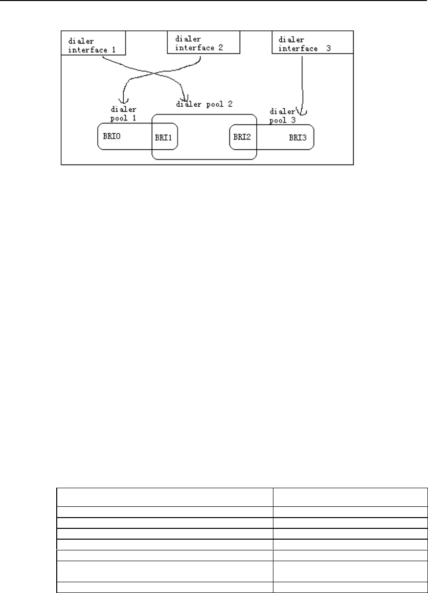
User Manual - Configuration Guide (Volume 3)
Versatile Routing Platform Chapter 1
DDR Configuration
1-12
Figure DC-1-3 Schematic diagram of the relation between dial interfaces, dialer pool and physical
interfaces
In the above diagram, dial interface 1 uses Dialer Pool 2, physical interface BRI 1
belongs to Dialer Pool 2, with a priority. Physical interface BRI 2 also belongs to Dialer
Pool 2, but with a different priority. For example, suppose that the priority of BRI 1 in
Dialer Pool 2 is 100 and that of BRI 2 is 50. Because the priority of BRI 1 is higher than
that of BRI 2, dial interface 1 will first select BRI 1 in Dialer Pool 2.
II. Configuration task list of Dialer Profile
The configuration tasks of Dialer Profile include:
z Configure a logic dial interface
z Set the attribute parameters of the logic dial interface
z Bind physical interfaces for a Dialer Pool
III. Configure a logic dial interface
Many logic dial interfaces (the specific number depends on router resources) can be
created in a router. Every logic dial interface includes all configurations required to
reach a destination network.
Follow the steps below to configure a logic dial interface. Please use the following
command in the configuration mode of the logic dial interface.
Table DC-1-21 Configure a logic dial interface
Operation Command
Set fast-idle time dialer fast-idle seconds
Set idle-timeout time dialer idle-timeout seconds
Set wait-for-carrier-time dialer wait-for-carrier-time seconds
Set autodial interval dialer autodial-interval seconds
Set hold-queue dialer hold-queue packets
Set load threshold (only in Dialer interface configuration mode) dialer load-threshold load [ either |
inbound | outbound ]
Set link disconnection time dialer enable-timeout seconds
IV. Set the attribute parameters of a dial interface
Please use the following command in the configuration mode of the logic dial interface.

User Manual - Configuration Guide (Volume 3)
Versatile Routing Platform Chapter 1
DDR Configuration
1-13
Table DC-1-22 Configure the features of the dial interface
Operation Command
Set fast-idle time dialer fast-idle seconds
Set idle-timeout time dialer idle-timeout seconds
Set wait-for-carrier-time dialer wait-for-carrier-time seconds
Set autodial interval dialer autodial-interval seconds
V. Bind physical interfaces for a dialer pool
The following steps are enough to bind a physical interface for a Dialer Pool.
Table DC-1-23 Configure a physical interface for a dialer pool
Operation Command
Enter the configuration mode of the designated physical
interface (used in global configuration mode) interface interface-type interface-number
Select PPP encapsulation (used in the configuration mode of
the designated physical interface) encapsulation ppp
Set CHAP authentication (used in the configuration mode of the
designated physical interface) ppp authentication chap
Designate this interface as a member of a Dialer Pool, and set
its priority (use this command again to designate this interface
as a member of another Dialer Pool at the same time) (used in
the configuration mode of the designated physical interface)
dialer pool-member number [ priority priority ]
1.4.3 Configuring Callback
I. The significance of callback
Callback enables “call receiver” to call back “call sender” so as to:
z Enhance security: in callback processing, Server end calls Client (as above) end
according to locally configured call number, thus avoiding insecurity due to
disclosed user name and password.
z Save call charge (when the charge rates of two directions are different).
z Change charge bearer.
z Combine charge lists.
II. Terms and abbreviations
z Client end: the first call originator, which requires the opposite end to call back the
local end.
z Server end: the first call receiver, which will call back the opposite end.
III. Functions implemented by callback
Callback requires the common participation of two ends, one as Client end and the
other as Server end. The basic operation flow is: Client end originates a call as “call
sender”, Server end determines whether to call back; if so, Server end disconnects the
incoming call, and sends a call to Client end.
VRP1.3 implements the following two callback functions:
1) In PPP callback, the following supports are considered:

User Manual - Configuration Guide (Volume 3)
Versatile Routing Platform Chapter 1
DDR Configuration
1-14
z General support (both ends have fixed network layer addresses and have
implemented RFC1570).
z Support when Client end needs dynamic distribution of network layer addresses.
z Support when only Server end has implemented RFC1570.
2) In ISDN environment, use ISDN calling line identification function to realize
callback.
IV. Configure ISDN calling line identification callback
To support ISDN calling line identification callback, a dialer caller command is provided
at ISDN interface.
1) The configurations when ISDN calling line identification callback is combined with
Legacy DDR.
Table DC-1-24 Use Legacy DDR to configure ISDN calling line identification callback
Operation Command
Enter the configuration mode of the designated dial
interface (used in global configuration mode) interface interface-type interface-number
Perform callback or connection for an incoming call that
matches remote-number (used in the configuration mode
of the dial interface)
dialer caller remote-number callback
or dialer caller remote-number
Set delay time before callback (used in the configuration
mode of the dial interface) dialer enable-timeout seconds
remote-number in dialer caller command refers to the telephone number of the remote
end.
2) The configurations when ISDN calling line identification callback is combined with
Dialer Profile.
Table DC-1-25 Use Dialer Profile to configure ISDN calling line identification callback
Operation Command
Enter the configuration mode of the logic dial interface
(used in global configuration mode) interface dialer interface-number
Perform callback or connection for an incoming call that
matches remote-number (used in the configuration mode
of the dial interface)
dialer caller remote-number callback
or dialer caller remote-number
Set delay time before callback (used in the configuration
mode of the dial interface) dialer enable-timeout seconds
3) Application features of ISDN calling line identification callback
i. An incoming call is processed in any of the following three ways based on the
matching of incoming call number and the locally configured dialer caller:
z Reject the incoming call—if dialer caller has been configured and the incoming call
number doesn’t have any matching dialer caller.
z Accept the incoming call—dialer caller has not been configured, or the incoming
call number matches the dialer caller without the key word “callback”.
z Callback—the incoming call number matches the dialer caller containing the key
word “callback”.

User Manual - Configuration Guide (Volume 3)
Versatile Routing Platform Chapter 1
DDR Configuration
1-15
ii. The matching between the incoming call number and dialer caller is “right end
matching”, with “*” representing any character.
iii. If multiple dialer callers match the incoming call number, then select one in line with
the following principle:
z Majority principle: first select the one with less “*”.
z Minority principle: first select the one that is found first.
iv. Specify the dialer caller related to an incoming call in line with the following principle:
z If the physical interface receiving the call is an interface bound by Legacy DDR,
then, in “dialer caller” configured by the logic dial interface to which it belongs,
search the dialer caller matching the incoming call number.
z If the physical interface receiving the call is an interface bound by Dialer Profile,
then, in all “dialer callers” configured by the logic dial interface to which it belongs,
search the dialer caller matching the incoming call number.
v. Before callback, take enable-timeout value configured at the corresponding dial
interface (or the physical interface that directly enables DDR) as the delay time.
vi. For an incoming call which is determined as needing callback according to dialer
caller, it is also necessary to configure, at the corresponding interface, dialer map
completely consistent with dial string and incoming call string (when combining with the
dialer string of Dialer Profile, dialer string has to be configured, which needn’t be
consistent with the incoming call string).
V. Configure PPP callback
In applying PPP callback, configure one end as Client end and the other end as Server
end.
1) The system provides three configuration commands to implement PPP callback
Please use the following two commands in the configuration mode of the dial interface.
Table DC-1-26 PPP callback commands in the configuration mode of the dial interface
Operation Command
Set the local end as callback Server end/Client end ppp callback accept | request
Configure callback by searching the matching dialer map
according to the name of the remote end or by the callback dial
string. At this time, dialer map command must contain name
parameter, otherwise callback is impossible
dialer callback-server username
or dialer callback-server dial-string
The first command is configured at Server end, used by DDR to determine whether to
call back by using the dial string provided PPP, or to call back according to the
configuration contents of dialer map.
The key word “accept” in the second command sets the router as Server end and the
key word “request” sets the router as Client end.
Please use the following command in global configuration mode.
Table DC-1-27 PPP callback command in global configuration mode
Operation Command
The call string for the local end to determine callback
according to the name of the remote end user name [callback-dialstring telephone-number]

User Manual - Configuration Guide (Volume 3)
Versatile Routing Platform Chapter 1
DDR Configuration
1-16
2) Use Legacy DDR to configure PPP callback
The configurations of Client end are shown in the following table.

User Manual - Configuration Guide (Volume 3)
Versatile Routing Platform Chapter 1
DDR Configuration
1-17
Table DC-1-28 Client end using Legacy DDR to configure PPP
Operation Command
Enter the configuration mode of the dial interface (used
in global configuration mode) interface interface-type interface-number
Select PPP encapsulation (used in the configuration
mode of the dial interface) encapsulation ppp
Set local end name and password for remote
authentication (used in the configuration mode of the dial
interface)
ppp pap sent-username name password {0 | 7}
password
or ppp chap host name
ppp chap password { 0 | 7 } password
Set the local end to authenticate the name and
password of the remote end in CHAP mode (used in
global configuration mode) user remotename password {0 | 7} password
Set the local end as callback Client end (used in the
configuration mode of the dial interface) ppp callback request
Set local call and dial strings (used in the configuration
mode of the dial interface) dialer map protocol nexthopaddr dial-string
The configurations of Server end are shown in the following table.
Table DC-1-29 Server end using Legacy DDR to configure PPP callback
Operation Command
Enter the configuration mode of the dial interface (used in
global configuration mode) interface interface-type interface-number
Select PPP encapsulation (used in the configuration mode of
the dial interface) encapsulation ppp
Set PPP authentication mode (used in the configuration mode
of the dial interface) ppp authentication pap
or ppp authentication chap
Set the local end as callback Server end (used in the
configuration mode of the dial interface) ppp callback accept
Configure callback by searching the matching dialer map
according to the name of the remote end or by the callback dial
string. At this time, dialer map command must contain name
parameter, otherwise callback is impossible (used in the
configuration mode of the dial interface)
dialer callback-server username
or dialer callback-server dial-string
If dialer callback-server dial-string has been configured,
callback dial string needs to be configured (used in global
configuration mode)
user name callback-dialstring telephone-
number
3) Use Dialer Profile to configure PPP callback
The configurations of Client end are shown in the following table.

User Manual - Configuration Guide (Volume 3)
Versatile Routing Platform Chapter 1
DDR Configuration
1-18
Table DC-1-30 Client end using Dialer Profile to configure PPP callback
Operation Command
Enter the configuration mode of the dial interface (used in global
configuration mode) interface dialer interface-number
Select PPP encapsulation (used in the configuration mode of the
dial interface) encapsulation ppp
Set local end name and password for remote authentication
ppp pap sent-username name password
{0 | 7} password
or ppp chap host name
ppp chap password {0 | 7} password
Set the local end to authenticate the name and password of the
remote end in chap mode (used in global configuration mode) user remotename password {0 | 7}
password
Set the local end as callback Client end (used in the configuration
mode of the dial interface) ppp callback request
Set local call and dial strings (used in the configuration mode of the
dial interface) dialer string dial-string
The configurations of Server end are shown in the following table.
Table DC-1-31 Server end using Dialer Profile to configure PPP callback
Operation Command
Enter the configuration mode of the dial interface (used in global
configuration mode) interface dialer interface-number
Select PPP encapsulation (used in the configuration mode of the
dial interface) encapsulation ppp
Set PPP authentication mode, which should be the same as that
selected by the Client end (used in the configuration mode of the
dial interface)
ppp authentication pap
or ppp authentication chap
Set the local end as callback Server end (used in the configuration
mode of the dial interface) ppp callback accept
Set callback based on callback dial string (used in the
configuration mode of the dial interface) dialer callback-server dial-string
Set callback dial string (used in global configuration mode) user name callback-dialstring telephone-
number
1.4.4 Configuring DDR Special Functions
I. Configure ISDN dedicated line
The essence of configuring ISDN is to establish a semi-permanent connection. ISDN
dedicated line configuration can only be used in combination with Legacy DDR
configuration. This function requires that the switch of the telecom office should have
corresponding dedicated lines connecting the remote equipment.
User Manual - Configuration Guide (Volume 3)
Versatile Routing Platform Chapter 1
DDR Configuration
1-19
Table DC-1-32 Use Legacy DDR to configure ISDN dedicated line
Operation Command
Configure dial string, according to which DDR
determines datagram (used in the configuration
mode of the dial interface)
dialer-list dialer-group protocol protocol-name {permit |
deny | list access-list-number}
Enter the configuration mode of the designated ISDN
interface (used in global configuration mode) interface interface-type interface-number
Set the ISDN interface to belong to a dialer group
(used in the configuration mode of ISDN interface) dialer-group number
Set B channel used to connect dedicated lines (used
in the configuration mode of ISDN interface) dialer isdn-leased channel-number
Configure dialer map (used in the configuration mode
of the dial interface) dialer map protocol next-hop-address dial-string
II. Configure autodial
Autodial means that when the router has been started, DDR will automatically try to
establish dial connection with the remote end, making it unnecessary to trigger
datagram. If dial connection fails, DDR will automatically try to establish dial connection
at regular intervals. Once the dial connection is established, it won’t disconnect itself
due to timeout (i.e. dialer idle-timeout is not functional).
Table DC-1-33 Configure autodial
Operation Command
Enter the configuration mode of the designated dial
interface (used in global configuration mode) interface interface-type interface-number
Configure dialer map for autodial (used in the
configuration mode of the dial interface) dialer map protocol next-hop-address name hostname
dialerstring [: isdnsubaddress] autodial
Set autodial interval (used in the configuration mode
of the dial interface) dialer autodial-interval seconds
Autodial interval is 300 seconds by default.
III. Configure cyclic use of dialer map
In dialer map configuration, the same destination network layer address can be
configured with multiple dialer maps, using different dial strings, thus forming dial string
backup between them. When DDR is establishing dial connection with the remote end,
if the dial string currently used can’t connect the remote end, then, in the next call, the
next dialer map and the dial string configured by it will be selected automatically. The
configurations are as follows:

User Manual - Configuration Guide (Volume 3)
Versatile Routing Platform Chapter 1
DDR Configuration
1-20
Table DC-1-34 Configure cyclic use of dialer map
Operation Command
Enter the configuration mode of the dial interface
(used in global configuration mode) interface interface-type interface-number
Configure dialer map (used in the configuration mode
of the dial interface) dialer map protocol next-hop-address name hostname
dialerstring [: isdn subaddress]
Configure several other dialer maps oriented to the
same destination network layer address and using
different dial strings (used in the configuration mode of
the dial interface)
dialer map protocol next-hop-address name hostname
dialerstring [: isdn subaddress]
1.5 Monitoring and Maintenance of DDR
In any configuration mode, the following command can be used to display dial interface
information, thus monitoring and maintaining DDR.
Table DC-1-35 Display DDR interface information
Operation Command
Display dial interface information show dialer [interface interface-type interface-number]
For example:
Quidway# show dialer interface serial 1
The system displays:
Serial1 - dialer type = Serial
NextHop_address Dialer_Strings Successes Failures Max_call
Last_call
100.1.1.1 8888
Idle timer (120 secs), Fast Idle timer (20 secs)
Wait for carrier (60 secs), Re_enable (20 secs)
The above includes dialer map table at the interface and such information as the
configuration of DDR features. Specific items are explained in the following table.
Table DC-1-36 Description of the display information items of show dialer command
Name Meaning
NextHop_address The address of the remote end corresponding to a Dialer
map at the interface
Dialer_Strings Dial string corresponding to the Dialer map
Successes Number of Dialer map call successes
Failures Number of Dialer map call failures
Max_call The maximum time Dialer map is used
Last_call The time Dialer map is used for the last call
Idle timer The time set by Dialer idle-timeout command
Fast Idle timer The time set by Dialer fast-idle command
Wait for carrier The time set by Dialer wait-for-carrier-time command
Re_enable The time set by Dialer enable-timeout command
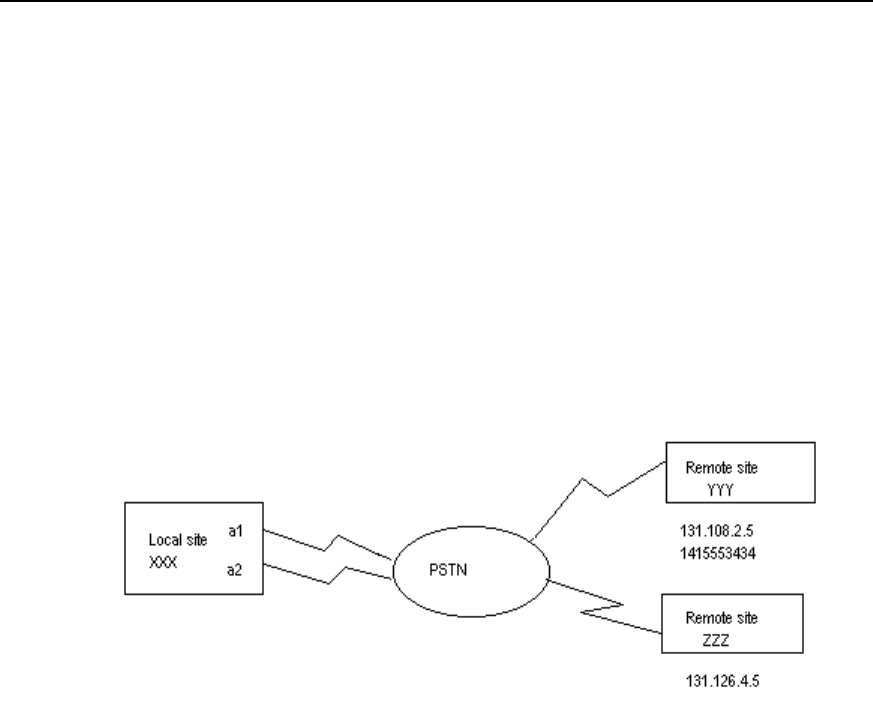
User Manual - Configuration Guide (Volume 3)
Versatile Routing Platform Chapter 1
DDR Configuration
1-21
1.6 DDR Typical Configuration Example
1.6.1 Legacy DDR
I. Network requirements
In the following diagram, the local router XXX and the remote routers YYY and ZZZ are
connected through DDR. Remote routers YYY and ZZZ can call the local router XXX,
while XXX can only call YYY, not ZZZ.
II. Networking diagram
Figure DC-1-4 Schematic diagram of a Legacy DDR configuration
III. Configuration procedure
! Create a dial interface
Quidway (config)# interface dialer 1
! Configure IP address of the dial interface
Quidway (config-if-Dialer1)# ip address 131.108.2.1 255.255.255.0
Quidway (config-if-Dialer1)# ip address 131.126.4.1 255.255.255.0 secondary
! Configure encapsulation PPP of the dial interface and CHAP authentication
Quidway (config-if-Dialer1)# encapsulation ppp
Quidway (config-if-Dialer1)# ppp authentication chap
! Configure domain name XXX of the local router
Quidway (config-if-Dialer1)# ppp chap host XXX (this name is the same as the user
name when the remote router configuration authenticates the local end. This will not be
explained further in later examples).
! Configure password xxxsystem when the local router is authenticated by the remote
router

User Manual - Configuration Guide (Volume 3)
Versatile Routing Platform Chapter 1
DDR Configuration
1-22
Quidway (config-if-Dialer1)# ppp chap password 0 xxxsystem
! Enable DDR in Legacy DDR mode
Quidway (config-if-Dialer1)# dialer in-band
! Designate the subordinate Group
Quidway (config-if-Dialer1)# dialer-group 1
! Indicating that the local end and YYY can send calls to and receive calls from each
other
Quidway (config-if-Dialer1)# dialer map ip 131.108.2.5 name YYY 1415553434
! Indicating that the local end can only receive calls from ZZZ
Quidway (config-if-Dialer1)# dialer map ip 131.126.4.5 name ZZZ
Quidway (config-if-Dialer1)# exit
! Set dial control
Quidway (config)# dialer-list 1 protocol ip permit
! Designate the asynchronous serial ports Serial0 and Serial1 to belong to rotary-group
1 (corresponding to interface dialer 1, which will not be explained further in later
examples).
Quidway (config)# interface serial 0
Quidway (config-if-Serial0)# dialer rotary-group 1
Set Serial0 to asynchronous mode and enable Modem attributes.
Quidway (config-if-Serial0)# physical-layer async
Quidway (config-if-Serial0)# modem
Quidway (config-if-Serial0)# exit
Quidway (config)# interface serial 1
Set Serial1 as asynchronous mode and enable Modem attributes.
Quidway (config-if-Serial1)# physical-layer async
Quidway (config-if-Serial1)# modem
Quidway (config-if-Serial1)# dialer rotary-group 1
! Configure remote user name and password for CHAP authentication: router YYY
password to be authenticated is yyysystem; router ZZZ password to be authenticated is
zzzsystem.
Quidway (config)# user YYY password 0 yyysystem
Quidway (config)# user ZZZ password 0 zzzsystem
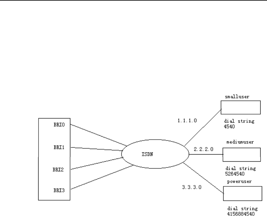
User Manual - Configuration Guide (Volume 3)
Versatile Routing Platform Chapter 1
DDR Configuration
1-23
1.6.2 Dialer Profile
I. Networking requirements
In the following diagram, the central router is connected to the remote end through four
ISDN BRI interfaces. It can send and receive calls. Each remote end is in a different IP
network section.
II. Networking diagram
Figure DC-1-5 Schematic diagram of a Dialer Profile configuration
III. Configuration procedure
! Create Dialer Profile going to IP subnetwork 1.1.1.0
Quidway(config)# interface dialer 1
Quidway(config-if-Dialer1)# no dialer in-band
Quidway(config-if-Dialer1)# ip address 1.1.1.1 255.255.255.0
Quidway(config-if-Dialer1)# encapsulation ppp
Quidway(config-if-Dialer1)# dialer remote-name Smalluser
Quidway(config-if-Dialer1)# dialer string 4540
Quidway(config-if-Dialer1)# dialer pool 3
Quidway(config-if-Dialer1)# dialer-group 1
Quidway(config-if-Dialer1)# exit
! Create Dialer Profile going to IP subnetwork 2.2.2.0
Quidway(config)# interface dialer 2
Quidway(config-if-Dialer2)# no dialer in-band
Quidway(config-if-Dialer2)# ip address 2.2.2.2 255.255.255.0

User Manual - Configuration Guide (Volume 3)
Versatile Routing Platform Chapter 1
DDR Configuration
1-24
Quidway(config-if-Dialer2)# encapsulation ppp
Quidway(config-if-Dialer2)# dialer remote-name Mediumuser
Quidway(config-if-Dialer2)# dialer string 5264540
Quidway(config-if-Dialer2)# dialer pool 1
Quidway(config-if-Dialer2)# dialer-group 2
! Create Dialer Profile going to IP subnetwork 3.3.3.0
Quidway(config)# interface dialer 3
Quidway(config-if-Dialer3)# no dialer in-band
Quidway(config-if-Dialer3)# ip address 3.3.3.3 255.255.255.0
Quidway(config-if-Dialer3)# encapsulation ppp
Quidway(config-if-Dialer3)# dialer remote-name Poweruser
Quidway(config-if-Dialer3)# dialer string 4156884540
Quidway(config-if-Dialer3)# dialer hold-queue 10
Quidway(config-if-Dialer3)# dialer pool 2
Quidway(config-if-Dialer3)# dialer-group 2
! Configure interface Bri0
Quidway(config)# interface bri 0
Quidway(config-if-Bri0)# encapsulation ppp
Quidway(config-if-Bri0)# dialer pool-member 1 priority 100
Quidway(config-if-Bri0)# ppp authentication chap
! Configure interface Bri1
Quidway(config)# interface bri 1
Quidway(config-if-Bri1)# encapsulation ppp
Quidway(config-if-Bri1)# dialer pool-member 1 priority 50
Quidway(config-if-Bri1)# dialer pool-member 2 priority 50
Quidway(config-if-Bri1)# dialer pool-member 3
Quidway(config-if-Bri1)# ppp authentication chap
! Configure interface Bri2
Quidway(config)# interface bri 2
Quidway(config-if-Bri2)# encapsulation ppp
Quidway(config-if-Bri2)# dialer pool-member 2 priority 100
Quidway(config-if-Bri2)# ppp authentication chap
! Configure interface Bri3
Quidway(config)# interface bri 3
Quidway(config-if-Bri3)# encapsulation ppp
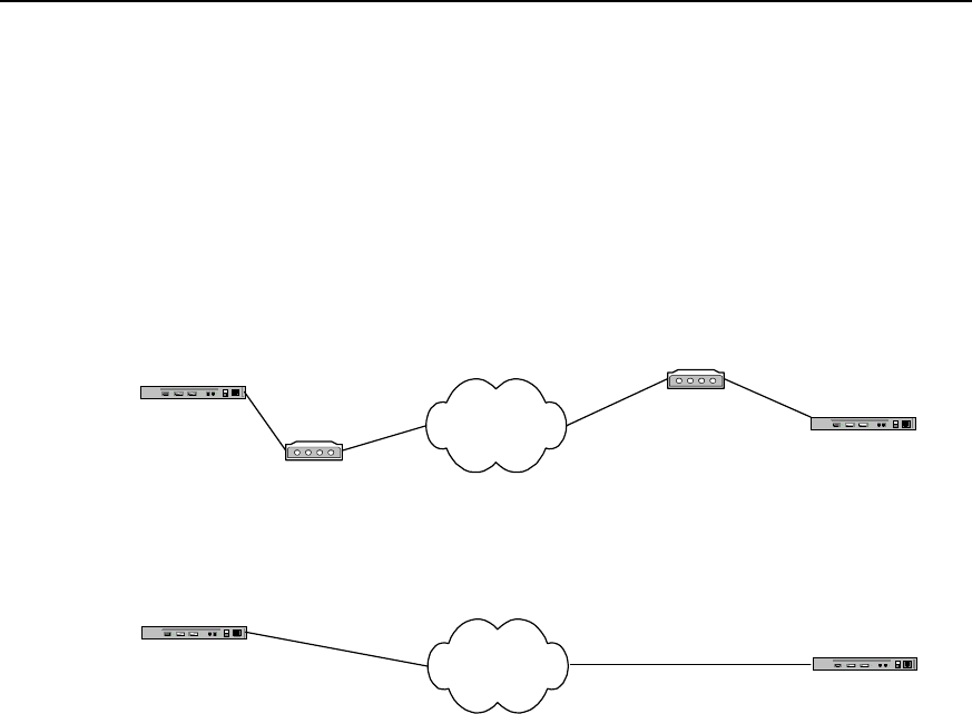
User Manual - Configuration Guide (Volume 3)
Versatile Routing Platform Chapter 1
DDR Configuration
1-25
Quidway(config-if-Bri3)# dialer pool-member 2 priority 150
Quidway(config-if-Bri3)# ppp authentication chap
! Configure remote user name and password for CHAP authentication and set dial
control. Please refer to Example 1 (omitted here).
1.6.3 Point-to-Point DDR
I. Networking diagram
Router A PSTN
Modem
Router B
Modem
8810052
8810048
Router A ISDN Router B
8810152
8810148
Connect through ISDN by using ISDN
Connect through PSTN
by using serial port
Figure DC-1-6 Networking diagram of point-to-point DDR configuration example
II. Configuration procedure
Solution 1: use Legacy DDR configuration mode to realize the following at the serial
port:
1) Configure router A:
Quidway(config)# dialer-list 1 protocol ip permit
Quidway(config)# interface serial 0
Quidway(config-if-Serial0)# ip address 100.1.1.1 255.255.255.0
Quidway(config-if-Serial0)# physical-layer async
Quidway(config-if-Serial0)# modem
Quidway(config-if-Serial0)# dialer in-band
Quidway(config-if-Serial0)# dialer-group 1
Quidway(config-if-Serial0)# dialer map ip 100.1.1.2 8810052
2) Configure router B:
Quidway(config)# dialer-list 1 protocol ip permit
Quidway(config)# interface serial 0
Quidway(config-if-Serial0)# ip address 100.1.1.2 255.255.255.0

User Manual - Configuration Guide (Volume 3)
Versatile Routing Platform Chapter 1
DDR Configuration
1-26
Quidway(config-if-Serial0)# physical-layer async
Quidway(config-if-Serial0)# modem
Quidway(config-if-Serial0)# dialer in-band
Quidway(config-if-Serial0)# dialer-group 1
Quidway(config-if-Serial0)# dialer map ip 100.1.1.1 8810048
Solution 2: use Dialer Profile configuration mode to realize the following at the serial
port:
1) Configure router A:
Quidway(config)# dialer-list 1 protocol ip permit
Quidway(config)# user userb password 0 passb
Quidway(config)# interface dialer 0
Quidway(config-if-Dialer0)# ip address 100.1.1.1 255.255.255.0
Quidway(config-if-Dialer0)# dialer remote-name userb
Quidway(config-if-Dialer0)# dialer-group 1
Quidway(config-if-Dialer0)# dialer string 8810052
Quidway(config-if-Dialer0)# dialer pool 1
Quidway(config-if-Dialer0)# ppp pap sent-username usera password 0 passa
Quidway(config-if-Dialer0)# interface serial 0
Quidway(config-if-Serial0)# physical-layer async
Quidway(config-if-Serial0)# modem
Quidway(config-if-Serial0)# dialer pool-member 1
Quidway(config-if-Serial0)# encapsulation ppp
Quidway(config-if-Serial0)# ppp authentication pap
2) Configure router B:
Quidway(config)# dialer-list 1 protocol ip permit
Quidway(config)# user usera password 0 passa
Quidway(config)# interface dialer 0
Quidway(config-if-Dialer0)# ip address 100.1.1.2 255.255.255.0
Quidway(config-if-Dialer0)# dialer remote-name usera
Quidway(config-if-Dialer0)# dialer-group 1
Quidway(config-if-Dialer0)# dialer string 8810048
Quidway(config-if-Dialer0)# dialer pool 1
Quidway(config-if-Dialer0)# ppp pap sent-username userb password 0 passb
Quidway(config-if-Dialer0)# interface serial 0
Quidway(config-if-Serial0)# physical-layer async

User Manual - Configuration Guide (Volume 3)
Versatile Routing Platform Chapter 1
DDR Configuration
1-27
Quidway(config-if-Serial0)# modem
Quidway(config-if-Serial0)# dialer pool-member 1
Quidway(config-if-Serial0)# encapsulation ppp
Quidway(config-if-Serial0)# ppp authentication pap
Solution 3: use Legacy DDR configuration mode to realize the following at ISDN BRI
and PRI interfaces:
1) Configure router A:
Quidway(config)# dialer-list 1 protocol ip permit
Quidway(config)# interface bri 0
Quidway(config-if-Bri0)# ip address 100.1.1.1 255.255.255.0
Quidway(config-if-Bri0)# dialer-group 1
Quidway(config-if-Bri0)# dialer map ip 100.1.1.2 8810152
2) Configure router B:
Quidway(config)# dialer-list 1 protocol ip permit
Quidway(config)# interface bri 0
Quidway(config-if-Bri0)# ip address 100.1.1.2 255.255.255.0
Quidway(config-if-Bri0)# dialer-group 1
Quidway(config-if-Bri0)# dialer map ip 100.1.1.1 8810148
Solution 4: use Dialer Profile configuration mode to realize the following at ISDN BRI
and PRI interfaces:
1) Configure router A:
Quidway(config)# dialer-list 1 protocol ip permit
Quidway(config)# user userb password 0 passb
Quidway(config)# interface dialer 0
Quidway(config-if-Dialer0)# ip address 100.1.1.1 255.255.255.0
Quidway(config-if-Dialer0)# dialer remote-name userb
Quidway(config-if-Dialer0)# dialer-group 1
Quidway(config-if-Dialer0)# dialer string 8810152
Quidway(config-if-Dialer0)# dialer pool 1
Quidway(config-if-Dialer0)# ppp pap sent-username usera password 0 passa
Quidway(config-if-Dialer0)# interface bri 0
Quidway(config-if-Bri0)# no dialer in-band
Quidway(config-if-Bri0)# dialer pool-member 1
Quidway(config-if-Bri0)# encapsulation ppp
Quidway(config-if-Bri0)# ppp authentication pap
2) Configure router B:
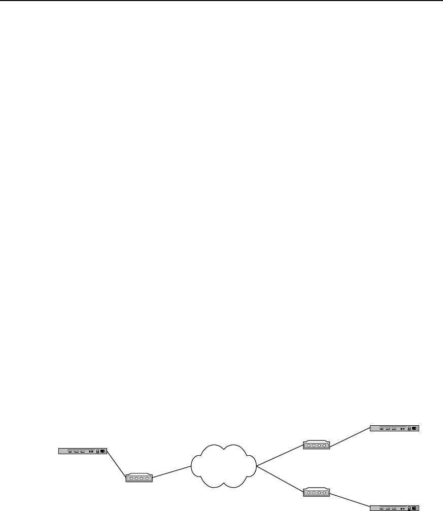
User Manual - Configuration Guide (Volume 3)
Versatile Routing Platform Chapter 1
DDR Configuration
1-28
Quidway(config)# dialer-list 1 protocol ip permit
Quidway(config)# user usera password 0 passa
Quidway(config)# interface dialer 0
Quidway(config-if-Dialer0)# ip address 100.1.1.2 255.255.255.0
Quidway(config-if-Dialer0)# dialer remote-name usera
Quidway(config-if-Dialer0)# dialer-group 1
Quidway(config-if-Dialer0)# dialer string 8810148
Quidway(config-if-Dialer0)# dialer pool 1
Quidway(config-if-Dialer0)# ppp pap sent-username userb password 0 passb
Quidway(config-if-Dialer0)# interface bri 0
Quidway(config-if-Bri0)# no dialer in-band
Quidway(config-if-Bri0)# dialer pool-member 1
Quidway(config-if-Bri0)# encapsulation ppp
Quidway(config-if-Bri0)# ppp authentication pap
1.6.4 Point-to-Multipoint DDR
I. Networking requirements
In the connection as shown in the following diagram, A and B can call each other, A and
C can call each other, but B and C can’t call each other.
II. Networking diagram
Router A PSTN
Modem
Router B
Modem
8810052
8810048
Modem
Router C
8810063
Connection Via serial port
through PSTN
Figure DC-1-7 Networking diagram of point-to-multipoint DDR configuration example
III. Configuration procedure
Solution 1: use Legacy DDR configuration mode to realize the following at the serial
port:
1) Configure router A:
Quidway(config)# dialer-list 1 protocol ip permit
Quidway(config)# interface serial 0

User Manual - Configuration Guide (Volume 3)
Versatile Routing Platform Chapter 1
DDR Configuration
1-29
Quidway(config-if-Serial0)# physical-layer async
Quidway(config-if-Serial0)# modem
Quidway(config-if-Serial0)# ip address 100.1.1.1 255.255.255.0
Quidway(config-if-Serial0)# dialer in-band
Quidway(config-if-Serial0)# dialer-group 1
Quidway(config-if-Serial0)# dialer map ip 100.1.1.2 8810052
Quidway(config-if-Serial0)# dialer map ip 100.1.1.3 8810063
2) Configure router B:
Quidway(config)# dialer-list 1 protocol ip permit
Quidway(config)# interface serial 0
Quidway(config-if-Serial0)# physical-layer async
Quidway(config-if-Serial0)# modem
Quidway(config-if-Serial0)# ip address 100.1.1.2 255.255.255.0
Quidway(config-if-Serial0)# dialer in-band
Quidway(config-if-Serial0)# dialer-group 1
Quidway(config-if-Serial0)# dialer map ip 100.1.1.1 8810048
3) Configure router C:
Quidway(config)# dialer-list 1 protocol ip permit
Quidway(config)# interface serial 0
Quidway(config-if-Serial0)# physical-layer async
Quidway(config-if-Serial0)# modem
Quidway(config-if-Serial0)# ip address 100.1.1.3 255.255.255.0
Quidway(config-if-Serial0)# dialer in-band
Quidway(config-if-Serial0)# dialer-group 1
Quidway(config-if-Serial0)# dialer map ip 100.1.1.1 8810048
Solution 2: use Dialer Profile configuration mode to realize the following at the serial
port:
1) Configure router A:
Quidway(config)# dialer-list 1 protocol ip permit
Quidway(config)# user userb password 0 passb
Quidway(config)# user userc password 0 passc
Quidway(config)# interface dialer 0
Quidway(config-if-Dialer0)# ip address 100.1.1.1 255.255.255.0
Quidway(config-if-Dialer0)# dialer remote-name userb
Quidway(config-if-Dialer0)# dialer-group 1

User Manual - Configuration Guide (Volume 3)
Versatile Routing Platform Chapter 1
DDR Configuration
1-30
Quidway(config-if-Dialer0)# ppp pap sent-username usera password 0 passa
Quidway(config-if-Dialer0)# dialer pool 1
Quidway(config-if-Dialer0)# dialer string 8810052
Quidway(config-if-Dialer0)# interface dialer 1
Quidway(config-if-Dialer1)# ip address 122.1.1.1 255.255.255.0
Quidway(config-if-Dialer1)# dialer remote-name userc
Quidway(config-if-Dialer1)# dialer-group 1
Quidway(config-if-Dialer1)# ppp pap sent-username usera password 0 passa
Quidway(config-if-Dialer1)# dialer pool 2
Quidway(config-if-Dialer1)# dialer string 8810063
Quidway(config-if-Dialer1)# interface serial 0
Quidway(config-if-Serial0)# physical-layer async
Quidway(config-if-Serial0)# modem
Quidway(config-if-Serial0)# dialer pool-member 1
Quidway(config-if-Serial0)# dialer pool-member 2
Quidway(config-if-Serial0)# encapsulation ppp
Quidway(config-if-Serial0)# ppp authentication pap
2) Configure router B:
Quidway(config)# dialer-list 1 protocol ip permit
Quidway(config)# user usera password 0 passa
Quidway(config)# interface dialer 0
Quidway(config-if-Dialer0)# ip address 100.1.1.2 255.255.255.0
Quidway(config-if-Dialer0)# dialer remote-name usera
Quidway(config-if-Dialer0)# dialer-group 1
Quidway(config-if-Dialer0)# dialer pool 1
Quidway(config-if-Dialer0)# ppp pap sent-username userb password 0 passb
Quidway(config-if-Dialer0)# dialer string 8810048
Quidway(config-if-Dialer0)# interface serial 0
Quidway(config-if-Serial0)# physical-layer async
Quidway(config-if-Serial0)# modem
Quidway(config-if-Serial0)# dialer pool-member 1
Quidway(config-if-Serial0)# encapsulation ppp
Quidway(config-if-Serial0)# ppp authentication pap
3) Configure router C:

User Manual - Configuration Guide (Volume 3)
Versatile Routing Platform Chapter 1
DDR Configuration
1-31
Quidway(config)# dialer-list 1 protocol ip permit
Quidway(config)# user usera password 0 passa
Quidway(config)# interface dialer 0
Quidway(config-if-Dialer0)# ip address 122.1.1.2 255.255.255.0
Quidway(config-if-Dialer0)# dialer remote-name usera
Quidway(config-if-Dialer0)# dialer-group 1
Quidway(config-if-Dialer0)# dialer pool 1
Quidway(config-if-Dialer0)# ppp pap sent-username userc password 0 passc
Quidway(config-if-Dialer0)# dialer string 8810048
Quidway(config-if-Dialer0)# interface serial 0
Quidway(config-if-Serial0)# physical-layer async
Quidway(config-if-Serial0)# modem
Quidway(config-if-Serial0)# dialer pool-member 1
Quidway(config-if-Serial0)# encapsulation ppp
Quidway(config-if-Serial0)# ppp authentication pap
1.6.5 Multipoint-to-Multipoint DDR
I. Networking requirements
In the connection as shown in the following diagram, A can establish calls with B and C
at the same time.
II. Networking diagram
Router A ISDN
Router B
8810152
Router C
8810163
Connection using ISDN BRI PRI
through ISDN
Router A Modem PSTN
Modem
Router B
Router C
Modem
Modem
8810052
8810054
8810055
8810048
Connection via serial port
through PSTN
8810148
Figure DC-1-8 Networking diagram of multipoint-to-multipoint DDR configuration example

User Manual - Configuration Guide (Volume 3)
Versatile Routing Platform Chapter 1
DDR Configuration
1-32
III. Configuration procedure
Solution 1: use Legacy DDR configuration mode to realize the following at the serial
port:
1) Configure router A:
Quidway(config)# dialer-list 1 protocol ip permit
Quidway(config)# interface dialer 0
Quidway(config-if-Dialer0)# ip address 100.1.1.1 255.255.255.0
Quidway(config-if-Dialer0)# dialer in-band
Quidway(config-if-Dialer0)# dialer-group 1
Quidway(config-if-Dialer0)# dialer map ip 100.1.1.2 8810055
Quidway(config-if-Dialer0)# dialer map ip 100.1.1.3 8810048
Quidway(config-if-Dialer0)# interface serial 0
Quidway(config-if-Serial0)# physical-layer async
Quidway(config-if-Serial0)# modem
Quidway(config-if-Serial0)# dialer rotary-group 0
Quidway(config-if-Serial0)# interface serial 1
Quidway(config-if-Serial1)# physical-layer async
Quidway(config-if-Serial1)# modem
Quidway(config-if-Serial1)# dialer rotary-group 0
2) Configure router B:
Quidway(config)# dialer-list 1 protocol ip permit
Quidway(config)# interface serial 0
Quidway(config-if-Serial0)# physical-layer async
Quidway(config-if-Serial0)# modem
Quidway(config-if-Serial0)# ip address 100.1.1.2 255.255.255.0
Quidway(config-if-Serial0)# dialer in-band
Quidway(config-if-Serial0)# dialer-group 1
Quidway(config-if-Serial0)# dialer map ip 100.1.1.1 8810052
Quidway(config-if-Serial0)# dialer map ip 100.1.1.1 8810054
3) Configure router C:
Quidway(config)# dialer-list 1 protocol ip permit
Quidway(config)# interface serial 0
Quidway(config-if-Serial0)# physical-layer async
Quidway(config-if-Serial0)# modem
Quidway(config-if-Serial0)# ip address 100.1.1.3 255.255.255.0

User Manual - Configuration Guide (Volume 3)
Versatile Routing Platform Chapter 1
DDR Configuration
1-33
Quidway(config-if-Serial0)# dialer in-band
Quidway(config-if-Serial0)# dialer-group 1
Quidway(config-if-Serial0)# dialer map ip 100.1.1.1 8810054
Quidway(config-if-Serial0)# dialer map ip 100.1.1.1 8810052
Solution 2: use Dialer Profile configuration mode to realize the following at the serial
port:
1) Configure router A:
Quidway(config)# dialer-list 1 protocol ip permit
Quidway(config)# user userb password 0 passb
Quidway(config)# user userc password 0 passc
Quidway(config)# interface dialer 0
Quidway(config-if-Dialer0)# ip address 100.1.1.1 255.255.255.0
Quidway(config-if-Dialer0)# dialer remote-name userb
Quidway(config-if-Dialer0)# dialer-group 1
Quidway(config-if-Dialer0)# ppp pap sent-username usera password 0 passa
Quidway(config-if-Dialer0)# dialer pool 1
Quidway(config-if-Dialer0)# dialer string 8810055
Quidway(config-if-Dialer0)# interface dialer 1
Quidway(config-if-Dialer1)# ip address 122.1.1.1 255.255.255.0
Quidway(config-if-Dialer1)# dialer remote-name userc
Quidway(config-if-Dialer1)# dialer-group 1
Quidway(config-if-Dialer1)# ppp pap sent-username usera password 0 passa
Quidway(config-if-Dialer1)# dialer pool 2
Quidway(config-if-Dialer1)# dialer string 8810048
Quidway(config-if-Dialer1)# interface serial 0
Quidway(config-if-Serial0)# physical-layer async
Quidway(config-if-Serial0)# modem
Quidway(config-if-Serial0)# dialer pool-member 1
Quidway(config-if-Serial0)# dialer pool-member 2
Quidway(config-if-Serial0)# encapsulation ppp
Quidway(config-if-Serial0)# ppp authentication pap
Quidway(config-if-Serial0)# interface serial 1
Quidway(config-if-Serial1)# physical-layer async
Quidway(config-if-Serial1)# modem

User Manual - Configuration Guide (Volume 3)
Versatile Routing Platform Chapter 1
DDR Configuration
1-34
Quidway(config-if-Serial1)# dialer pool-member 1
Quidway(config-if-Serial1)# dialer pool-member 2
Quidway(config-if-Serial1)# encapsulation ppp
Quidway(config-if-Serial1)# ppp authentication pap
2) Configure router B:
Quidway(config)# dialer-list 1 protocol ip permit
Quidway(config)# user usera password 0 passa
Quidway(config)# interface dialer 0
Quidway(config-if-Dialer0)# ip address 100.1.1.2 255.255.255.0
Quidway(config-if-Dialer0)# dialer remote-name usera
Quidway(config-if-Dialer0)# dialer-group 1
Quidway(config-if-Dialer0)# dialer pool 1
Quidway(config-if-Dialer0)# ppp pap sent-username userb password 0 passb
Quidway(config-if-Dialer0)# dialer string 8810052
Quidway(config-if-Dialer0)# interface serial 0
Quidway(config-if-Serial0)# physical-layer async
Quidway(config-if-Serial0)# modem
Quidway(config-if-Serial0)# dialer pool-member 1
Quidway(config-if-Serial0)# encapsulation ppp
Quidway(config-if-Serial0)# ppp authentication pap
3) Configure router C:
Quidway(config)# dialer-list 1 protocol ip permit
Quidway(config)# user usera password 0 passa
Quidway(config)# interface dialer 0
Quidway(config-if-Dialer0)# ip address 122.1.1.2 255.255.255.0
Quidway(config-if-Dialer0)# dialer remote-name usera
Quidway(config-if-Dialer0)# dialer-group 1
Quidway(config-if-Dialer0)# dialer pool 1
Quidway(config-if-Dialer0)# ppp pap sent-username userc password 0 passc
Quidway(config-if-Dialer0)# dialer string 8810054
Quidway(config-if-Dialer0)# interface serial 0
Quidway(config-if-Serial0)# physical-layer async
Quidway(config-if-Serial0)# modem
Quidway(config-if-Serial0)# dialer pool-member 1

User Manual - Configuration Guide (Volume 3)
Versatile Routing Platform Chapter 1
DDR Configuration
1-35
Quidway(config-if-Serial0)# encapsulation ppp
Quidway(config-if-Serial0)# ppp authentication pap
Solution 3: use Legacy DDR configuration mode to realize the following at ISDN BRI
and PRI interfaces:
1) Configure router A:
Quidway(config)# dialer-list 1 protocol ip permit
Quidway(config)# interface bri 0
Quidway(config-if-Bri0)# ip address 100.1.1.1 255.255.255.0
Quidway(config-if-Bri0)# dialer-group 1
Quidway(config-if-Bri0)# dialer map ip 100.1.1.2 8810152
Quidway(config-if-Bri0)# dialer map ip 100.1.1.3 8810163
2) Configure router B:
Quidway(config)# dialer-list 1 protocol ip permit
Quidway(config)# interface bri 0
Quidway(config-if-Bri0)# ip address 100.1.1.2 255.255.255.0
Quidway(config-if-Bri0)# dialer-group 1
Quidway(config-if-Bri0)# dialer map ip 100.1.1.1 8810148
3) Configure router C:
Quidway(config)# dialer-list 1 protocol ip permit
Quidway(config)# interface bri 0
Quidway(config-if-Bri0)# ip address 100.1.1.3 255.255.255.0
Quidway(config-if-Bri0)# dialer-group 1
Quidway(config-if-Bri0)# dialer map ip 100.1.1.1 8810148
Solution 4: use Dialer Profile configuration mode to realize the following at ISDN BRI
and PRI interfaces:
1) Configure router A:
Quidway(config)# dialer-list 1 protocol ip permit
Quidway(config)# user userb password 0 passb
Quidway(config)# user userc password 0 passc
Quidway(config)# interface dialer 0
Quidway(config-if-Dialer0)# ip address 100.1.1.1 255.255.255.0
Quidway(config-if-Dialer0)# dialer remote-name userb
Quidway(config-if-Dialer0)# dialer-group 1
Quidway(config-if-Dialer0)# ppp pap sent-username usera password 0 passa
Quidway(config-if-Dialer0)# dialer pool 1
Quidway(config-if-Dialer0)# dialer string 8810152

User Manual - Configuration Guide (Volume 3)
Versatile Routing Platform Chapter 1
DDR Configuration
1-36
Quidway(config-if-Dialer0)# interface dialer 1
Quidway(config-if-Dialer1)# ip address 122.1.1.1 255.255.255.0
Quidway(config-if-Dialer1)# dialer remote-name userc
Quidway(config-if-Dialer1)# dialer-group 1
Quidway(config-if-Dialer1)# ppp pap sent-username usera password 0 passa
Quidway(config-if-Dialer1)# dialer pool 2
Quidway(config-if-Dialer1)# dialer string 8810163
Quidway(config-if-Dialer1)# interface bri 0
Quidway(config-if-Bri0)# no dialer in-band
Quidway(config-if-Bri0)# dialer pool-member 1
Quidway(config-if-Bri0)# dialer pool-member 2
Quidway(config-if-Bri0)# encapsulation ppp
Quidway(config-if-Bri0)# ppp authentication pap
2) Configure router B:
Quidway(config)# dialer-list 1 protocol ip permit
Quidway(config)# user usera password 0 passa
Quidway(config)# interface dialer 0
Quidway(config-if-Dialer0)# ip address 100.1.1.2 255.255.255.0
Quidway(config-if-Dialer0)# dialer remote-name usera
Quidway(config-if-Dialer0)# dialer-group 1
Quidway(config-if-Dialer0)# dialer pool 1
Quidway(config-if-Dialer0)# ppp pap sent-username userb password 0 passb
Quidway(config-if-Dialer0)# dialer string 8810148
Quidway(config-if-Dialer0)# interface bri 0
Quidway(config-if-Bri0)# no dialer in-band
Quidway(config-if-Bri0)# dialer pool-member 1
Quidway(config-if-Bri0)# encapsulation ppp
Quidway(config-if-Bri0)# ppp authentication pap
3) Configure router C:
Quidway(config)# dialer-list 1 protocol ip permit
Quidway(config)# user usera password 0 passa
Quidway(config)# interface dialer 0
Quidway(config-if-Dialer0)# ip address 122.1.1.2 255.255.255.0
Quidway(config-if-Dialer0)# dialer remote-name usera
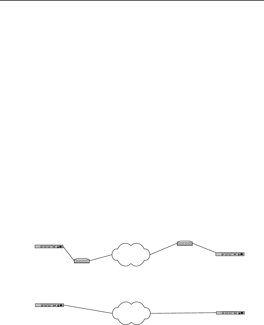
User Manual - Configuration Guide (Volume 3)
Versatile Routing Platform Chapter 1
DDR Configuration
1-37
Quidway(config-if-Dialer0)# dialer-group 1
Quidway(config-if-Dialer0)# dialer pool 1
Quidway(config-if-Dialer0)# ppp pap sent-username userc password 0 passc
Quidway(config-if-Dialer0)# dialer string 8810148
Quidway(config-if-Dialer0)# interface bri 0
Quidway(config-if-Bri0)# no dialer in-band
Quidway(config-if-Bri0)# dialer pool-member 1
Quidway(config-if-Bri0)# encapsulation ppp
Quidway(config-if-Bri0)# ppp authentication pap
1.6.6 DDR Bearing IPX
DDR can bear both IP network layer protocol and IPX network layer protocol. Make the
following three modifications to the above-mentioned various solutions, and it is
possible to connect DDR bearing IPX.
z Replace the statements configuring IP network layer addresses of various
interfaces with the statements configuring IPX addresses;
z Replace the IP address in dialer map configuration command with IPX address;
z Change ip in dialer-list configuration command into ipx.
The following is the implementation solution of DDR bearing IPX and oriented to
point-to-point connection. Its hardware configurations and dial string configurations are
the same as the configurations in the example “Point-to-Point DDR”.
I. Networking diagram
Router A PSTN
Modem Router B
Modem
8810052
8810048
Router A ISDN Router B
8810152
8810148
Connection using ISDN BRI PRI
through ISDN
Connection via serial port
through PSTN
Figure DC-1-9 Networking diagram of the configuration example of DDR bearing IPX
II. Configuration procedure
Solution 1: use Legacy DDR configuration mode to realize the following at the serial
port:
1) Configure router A:

User Manual - Configuration Guide (Volume 3)
Versatile Routing Platform Chapter 1
DDR Configuration
1-38
Quidway(config)# dialer-list 1 protocol ipx permit
Quidway(config)# ipx routing 1.1.1
Quidway(config)# interface serial 0
Quidway(config-if-Serial0)# ipx network 1
Quidway(config-if-Serial0)# physical-layer async
Quidway(config-if-Serial0)# modem
Quidway(config-if-Serial0)# dialer in-band
Quidway(config-if-Serial0)# dialer-group 1
2) Quidway(config-if-Serial0)# dialer map ipx 1.1.1.2 8810052Configure router B:
Quidway(config)# dialer-list 1 protocol ipx permit
Quidway(config)# ipx routing 1.1.2
Quidway(config)# interface serial 0
Quidway(config-if-Serial0)# ipx network 1
Quidway(config-if-Serial0)# physical-layer async
Quidway(config-if-Serial0)# modem
Quidway(config-if-Serial0)# dialer in-band
Quidway(config-if-Serial0)# dialer-group 1
Quidway(config-if-Serial0)# dialer map ipx 1.1.1.1 8810048
Solution 2: use Dialer Profile configuration mode to realize the following at the serial
port:
1) Configure router A:
Quidway(config)# dialer-list 1 protocol ipx permit
Quidway(config)# ipx routing 1.1.1
Quidway(config)# user userb password 0 passb
Quidway(config)# interface dialer 0
Quidway(config-if-Dialer0)# ipx network 1
Quidway(config-if-Dialer0)# dialer remote-name userb
Quidway(config-if-Dialer0)# dialer-group 1
Quidway(config-if-Dialer0)# dialer string 8810052
Quidway(config-if-Dialer0)# dialer pool 1
Quidway(config-if-Dialer0)# ppp pap sent-username usera password 0 passa
Quidway(config-if-Dialer0)# interface serial 0
Quidway(config-if-Serial0)# physical-layer async
Quidway(config-if-Serial0)# modem
Quidway(config-if-Serial0)# dialer pool-member 1

User Manual - Configuration Guide (Volume 3)
Versatile Routing Platform Chapter 1
DDR Configuration
1-39
Quidway(config-if-Serial0)# encapsulation ppp
Quidway(config-if-Serial0)# ppp authentication pap
2) Configure router B:
Quidway(config)# dialer-list 1 protocol ipx permit
Quidway(config)# ipx routing 1.1.2
Quidway(config)# user usera password 0 passa
Quidway(config)# interface dialer 0
Quidway(config-if-Dialer0)# ipx network 1
Quidway(config-if-Dialer0)# dialer remote-name usera
Quidway(config-if-Dialer0)# dialer-group 1
Quidway(config-if-Dialer0)# dialer string 8810048
Quidway(config-if-Dialer0)# dialer pool 1
Quidway(config-if-Dialer0)# ppp pap sent-username userb password 0 passb
Quidway(config-if-Dialer0)# interface serial 0
Quidway(config-if-Serial0)# physical-layer async
Quidway(config-if-Serial0)# modem
Quidway(config-if-Serial0)# dialer pool-member 1
Quidway(config-if-Serial0)# encapsulation ppp
Quidway(config-if-Serial0)# ppp authentication pap
Solution 3: use Legacy DDR configuration mode to realize the following at ISDN BRI
and PRI interfaces:
1) Configure router A:
Quidway(config)# dialer-list 1 protocol ipx permit
Quidway(config)# ipx routing 1.1.1
Quidway(config)# interface bri 0
Quidway(config-if-Bri0)# ipx network 1
Quidway(config-if-Bri0)# dialer-group 1
Quidway(config-if-Bri0)# dialer map ipx 1.1.1.2 8810152
2) Configure router B:
Quidway(config)# dialer-list 1 protocol ipx permit
Quidway(config)# ipx routing 1.1.2
Quidway(config)# interface bri 0
Quidway(config-if-Bri0)# ipx network 1
Quidway(config-if-Bri0)# dialer-group 1
Quidway(config-if-Bri0)# dialer map ipx 1.1.1.1 8810148

User Manual - Configuration Guide (Volume 3)
Versatile Routing Platform Chapter 1
DDR Configuration
1-40
Solution 4: use Dialer Profile configuration mode to realize the following at ISDN BRI
and PRI interfaces
1) Configure router A:
Quidway(config)# dialer-list 1 protocol ipx permit
Quidway(config)# ipx routing 1.1.1
Quidway(config)# user userb password 0 passb
Quidway(config)# interface dialer 0
Quidway(config-if-Dialer0)# ipx network 1
Quidway(config-if-Dialer0)# dialer remote-name userb
Quidway(config-if-Dialer0)# dialer-group 1
Quidway(config-if-Dialer0)# dialer string 8810152
Quidway(config-if-Dialer0)# dialer pool 1
Quidway(config-if-Dialer0)# ppp pap sent-username usera password 0 passa
Quidway(config-if-Dialer0)# interface bri 0
Quidway(config-if-Bri0)# no dialer in-band
Quidway(config-if-Bri0)# dialer pool-member 1
Quidway(config-if-Bri0)# encapsulation ppp
Quidway(config-if-Bri0)# ppp authentication pap
2) Configure router B:
Quidway(config)# dialer-list 1 protocol ipx permit
Quidway(config)# ipx network 1.1.2
Quidway(config)# user usera password 0 passa
Quidway(config)# interface dialer 0
Quidway(config-if-Dialer0)# ipx network 1
Quidway(config-if-Dialer0)# dialer remote-name usera
Quidway(config-if-Dialer0)# dialer-group 1
Quidway(config-if-Dialer0)# dialer string 8810148
Quidway(config-if-Dialer0)# dialer pool 1
Quidway(config-if-Dialer0)# ppp pap sent-username userb password 0 passb
Quidway(config-if-Dialer0)# interface bri 0
Quidway(config-if-Bri0)# no dialer in-band
Quidway(config-if-Bri0)# dialer pool-member 1
Quidway(config-if-Bri0)# encapsulation ppp
Quidway(config-if-Bri0)# ppp authentication pap
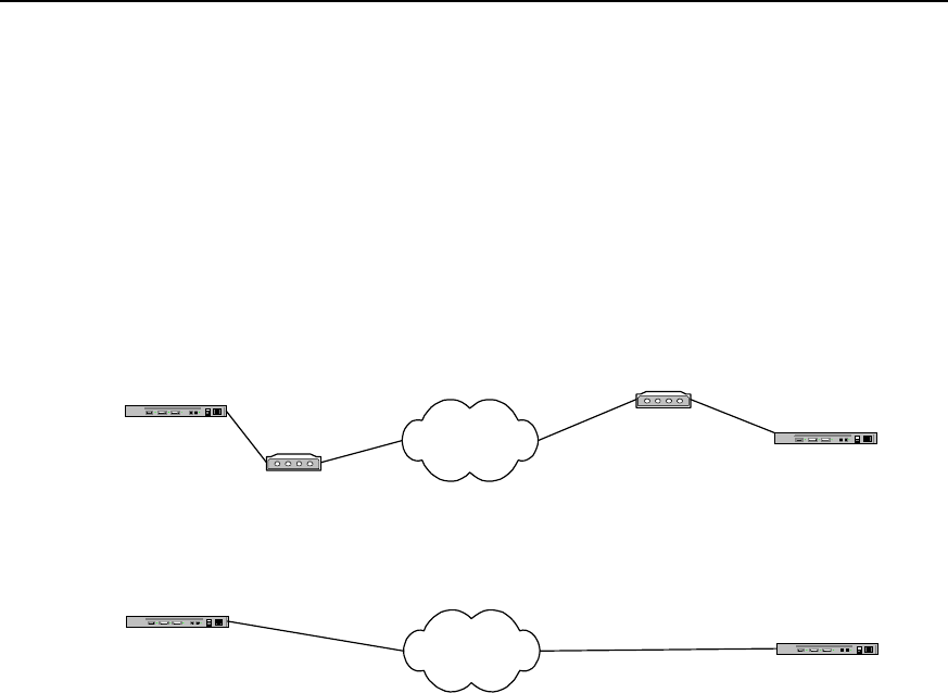
User Manual - Configuration Guide (Volume 3)
Versatile Routing Platform Chapter 1
DDR Configuration
1-41
1.6.7 DDR Bearing IP and IPX at the Same Time
DDR can bear IP and IPX at the same time on one dial connection. That is, when a call
connection has been established, IP message and IPX message can be sent at the
same time on this connection.
The following is the implementation solution of DDR bearing IP and IPX at the same
time and oriented to point-to-point connection. Its hardware configurations and dial
string configurations are the same as the configurations in the example “Point-to-Point
DDR”
I. Networking diagram
Router A PSTN
Modem Router B
Modem
8810052
8810048
Router A ISDN Router B
8810152
8810148
Connection using ISDN BRI PRI
through ISDN
Connection via serial port
through PSTN
Figure DC-1-10 Networking diagram of DDR configuration bearing IP and IPX at the same time
II. Configuration procedure
Solution 1: use Legacy DDR configuration mode to realize the following at the serial
port:
1) Configure router A:
Quidway(config)# dialer-list 1 protocol ip permit
Quidway(config)# dialer-list 1 protocol ipx permit
Quidway(config)# ipx routing 1.1.1
Quidway(config)# interface serial 0
Quidway(config-if-Serial0)# ip address 100.1.1.1 255.255.255.0
Quidway(config-if-Serial0)# ipx network 1
Quidway(config-if-Serial0)# physical-layer async
Quidway(config-if-Serial0)# modem
Quidway(config-if-Serial0)# dialer in-band
Quidway(config-if-Serial0)# dialer-group 1
Quidway(config-if-Serial0)# dialer map ip 100.1.1.2 8810052

User Manual - Configuration Guide (Volume 3)
Versatile Routing Platform Chapter 1
DDR Configuration
1-42
Quidway(config-if-Serial0)# dialer map ipx 1.1.1.2 8810052
2) Configure router B:
Quidway(config)# dialer-list 1 protocol ip permit
Quidway(config)# dialer-list 1 protocol ipx permit
Quidway(config)# ipx routing 1.1.2
Quidway(config)# interface serial 0
Quidway(config-if-Serial0)# ip address 100.1.1.2 255.255.255.0
Quidway(config-if-Serial0)# ipx network 1
Quidway(config-if-Serial0)# physical-layer async
Quidway(config-if-Serial0)# modem
Quidway(config-if-Serial0)# dialer in-band
Quidway(config-if-Serial0)# dialer-group 1
Quidway(config-if-Serial0)# dialer map ip 100.1.1.1 8810048
Quidway(config-if-Serial0)# dialer map ipx 1.1.1.1 8810048
Solution 2: use Dialer Profile configuration mode to realize the following at the serial
port:
1) Configure router A:
Quidway(config)# dialer-list 1 protocol ip permit
Quidway(config)# dialer-list 1 protocol ipx permit
Quidway(config)# ipx routing 1.1.1
Quidway(config)# user userb password 0 passb
Quidway(config)# interface dialer 0
Quidway(config-if-Dialer0)# ip address 100.1.1.1 255.255.255.0
Quidway(config-if-Dialer0)# ipx network 1
Quidway(config-if-Dialer0)# dialer remote-name userb
Quidway(config-if-Dialer0)# dialer-group 1
Quidway(config-if-Dialer0)# dialer string 8810052
Quidway(config-if-Dialer0)# dialer pool 1
Quidway(config-if-Dialer0)# ppp pap sent-username usera password 0 passa
Quidway(config-if-Dialer0)# interface serial 0
Quidway(config-if-Serial0)# physical-layer async
Quidway(config-if-Serial0)# modem
Quidway(config-if-Serial0)# dialer pool-member 1
Quidway(config-if-Serial0)# encapsulation ppp
Quidway(config-if-Serial0)# ppp authentication pap

User Manual - Configuration Guide (Volume 3)
Versatile Routing Platform Chapter 1
DDR Configuration
1-43
2) Configure router B:
Quidway(config)# dialer-list 1 protocol ip permit
Quidway(config)# dialer-list 1 protocol ipx permit
Quidway(config)# ipx routing 1.1.2
Quidway(config)# user usera password 0 passa
Quidway(config)# interface dialer 0
Quidway(config-if-Dialer0)# ip address 100.1.1.2 255.255.255.0
Quidway(config-if-Dialer0)# ipx network 1
Quidway(config-if-Dialer0)# dialer remote-name usera
Quidway(config-if-Dialer0)# dialer-group 1
Quidway(config-if-Dialer0)# dialer string 8810048
Quidway(config-if-Dialer0)# dialer pool 1
Quidway(config-if-Dialer0)# ppp pap sent-username userb password 0 passb
Quidway(config-if-Dialer0)# interface serial 0
Quidway(config-if-Serial0)# physical-layer async
Quidway(config-if-Serial0)# modem
Quidway(config-if-Serial0)# dialer pool-member 1
Quidway(config-if-Serial0)# encapsulation ppp
Quidway(config-if-Serial0)# ppp authentication pap
Solution 3: use Legacy DDR configuration mode to realize the following at ISDN BRI
and PRI interfaces:
1) Configure router A:
Quidway(config)# dialer-list 1 protocol ip permit
Quidway(config)# dialer-list 1 protocol ipx permit
Quidway(config)# ipx routing 1.1.1
Quidway(config)# interface bri 0
Quidway(config-if-Bri0)# ip address 100.1.1.1 255.255.255.0
Quidway(config-if-Bri0)# ipx network 1
Quidway(config-if-Bri0)# dialer-group 1
Quidway(config-if-Bri0)# dialer map ip 100.1.1.2 8810152
Quidway(config-if-Bri0)# dialer map ipx 1.1.1.2 8810152
2) Configure router B:
Quidway(config)# dialer-list 1 protocol ip permit
Quidway(config)# dialer-list 1 protocol ipx permit
Quidway(config)# ipx routing 1.1.2

User Manual - Configuration Guide (Volume 3)
Versatile Routing Platform Chapter 1
DDR Configuration
1-44
Quidway(config)# interface bri 0
Quidway(config-if-Bri0)# ip address 100.1.1.2 255.255.255.0
Quidway(config-if-Bri0)# ipx network 1
Quidway(config-if-Bri0)# dialer-group 1
Quidway(config-if-Bri0)# dialer map ip 100.1.1.1 8810148
Quidway(config-if-Bri0)# dialer map ipx 1.1.1.1 8810148
Solution 4: use Dialer Profile configuration mode to realize the following at ISDN BRI
and PRI interfaces:
1) Configure router A:
Quidway(config)# dialer-list 1 protocol ip permit
Quidway(config)# dialer-list 1 protocol ipx permit
Quidway(config)# ipx routing 1.1.1
Quidway(config)# user userb password 0 passb
Quidway(config)# interface dialer 0
Quidway(config-if-Dialer0)# ip address 100.1.1.1 255.255.255.0
Quidway(config-if-Dialer0)# ipx network 1
Quidway(config-if-Dialer0)# dialer remote-name userb
Quidway(config-if-Dialer0)# dialer-group 1
Quidway(config-if-Dialer0)# dialer string 8810152
Quidway(config-if-Dialer0)# dialer pool 1
Quidway(config-if-Dialer0)# ppp pap sent-username usera password 0 passa
Quidway(config-if-Dialer0)# interface bri 0
Quidway(config-if-Bri0)# no dialer in-band
Quidway(config-if-Bri0)# dialer pool-member 1
Quidway(config-if-Bri0)# encapsulation ppp
Quidway(config-if-Bri0)# ppp authentication pap
2) Configure router B:
Quidway(config)# dialer-list 1 protocol ip permit
Quidway(config)# dialer-list 1 protocol ipx permit
Quidway(config)# ipx routing 1.1.2
Quidway(config)# user usera password 0 passa
Quidway(config)# interface dialer 0
Quidway(config-if-Dialer0)# ip address 100.1.1.2 255.255.255.0
Quidway(config-if-Dialer0)# ipx network 1
Quidway(config-if-Dialer0)# dialer remote-name usera
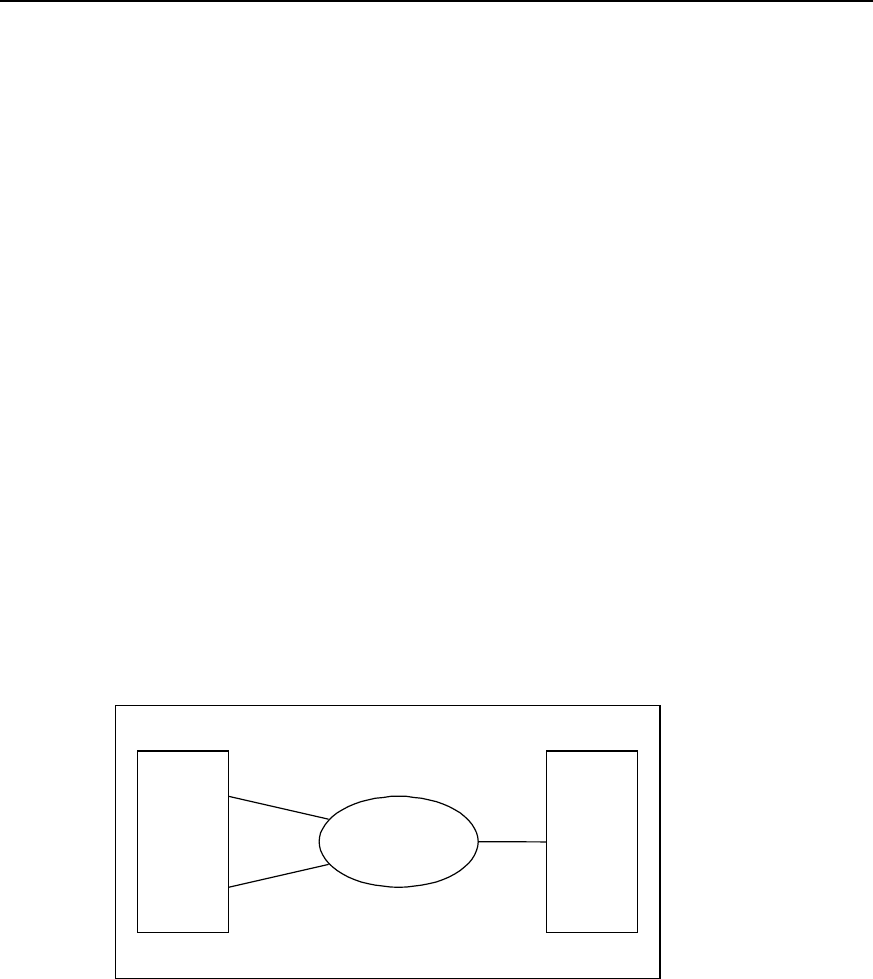
User Manual - Configuration Guide (Volume 3)
Versatile Routing Platform Chapter 1
DDR Configuration
1-45
Quidway(config-if-Dialer0)# dialer-group 1
Quidway(config-if-Dialer0)# dialer string 8810148
Quidway(config-if-Dialer0)# dialer pool 1
Quidway(config-if-Dialer0)# ppp pap sent-username userb password 0 passb
Quidway(config-if-Dialer0)# interface bri 0
Quidway(config-if-Bri0)# no dialer in-band
Quidway(config-if-Bri0)# dialer pool-member 1
Quidway(config-if-Bri0)# encapsulation ppp
Quidway(config-if-Bri0)# ppp authentication pap
1.6.8 Flow Control of Dialer Profile (MP over Dialer Profile)-Case 1
By setting flow load threshold to control flow distribution, bandwidth can be distributed
in real-time and maximum bandwidth can be provided.
I. Networking requirements
In the following diagram, local router and remote router are interconnected through two
BRI interface. Bandwidth should be provided according to the real flow.
II. Networking diagram
ISDN PRI0
2.2.2.2
661012
BRI0 660368
BRI1 660378
RouterA RouterB
Figure DC-1-11 Networking diagram of DDR – Case 1
III. Configuration procedure
1) Configure router A:
Quidway(config)# dialer-list 1 protocol ip permit
Quidway(config)# user userb password 0 passb
Quidway(config)# flow-interval 3
Quidway(config)# interface dialer 0
Quidway(config-if-Dialer0)# ip address 2.2.2.1 255.255.255.0

User Manual - Configuration Guide (Volume 3)
Versatile Routing Platform Chapter 1
DDR Configuration
1-46
Quidway(config-if-Dialer0)# encapsulation ppp
Quidway(config-if-Dialer0)# ppp pap sent-username usera password 0 passa
Quidway(config-if-Dialer0)# ppp multilink
Quidway(config-if-Dialer0)# dialer remote-name userb
Quidway(config-if-Dialer0)# dialer string 661012
Quidway(config-if-Dialer0)# dialer pool 1
Quidway(config-if-Dialer0)# dialer-group 1
Quidway(config-if-Dialer0)# dialer load-threshold 80
! Configure physical interface
Quidway(config)# interface bri 0
Quidway(config-if-Bri0)# no dialer in-band
Quidway(config-if-Bri0)# encapsulation ppp
Quidway(config-if-Bri0)# ppp multilink
Quidway(config-if-Bri0)# dialer pool-member 1
Quidway(config-if-Bri0)# ppp authentication pap
Quidway(config-if-Bri0)# ppp pap sent-username usera password 0 passa
Quidway(config)# interface bri 1
Quidway(config-if-Bri1)# no dialer in-band
Quidway(config-if-Bri1)# encapsulation ppp
Quidway(config-if-Bri1)# ppp multilink
Quidway(config-if-Bri1)# dialer pool-member 1
Quidway(config-if-Bri1)# ppp authentication pap
Quidway(config-if-Bri1)# ppp pap sent-username usera password 0 passa
2) Configure router B:
Quidway(config)# dialer-list 1 protocol ip permit
Quidway(config)# user usera password 0 passa
Quidway(config)# flow-interval 3
Quidway(config)# controler e1 0
Quidway(config-if-E1-0)# pri-group
Quidway(config-if-E1-0)# interface Serial 0:15
Quidway(config-if-Serial0:15)# encapsulation ppp
Quidway(config-if-Serial0:15)# ppp multilink
Quidway(config-if-Serial0:15)# ip address 2.2.2.1 255.255.255.0
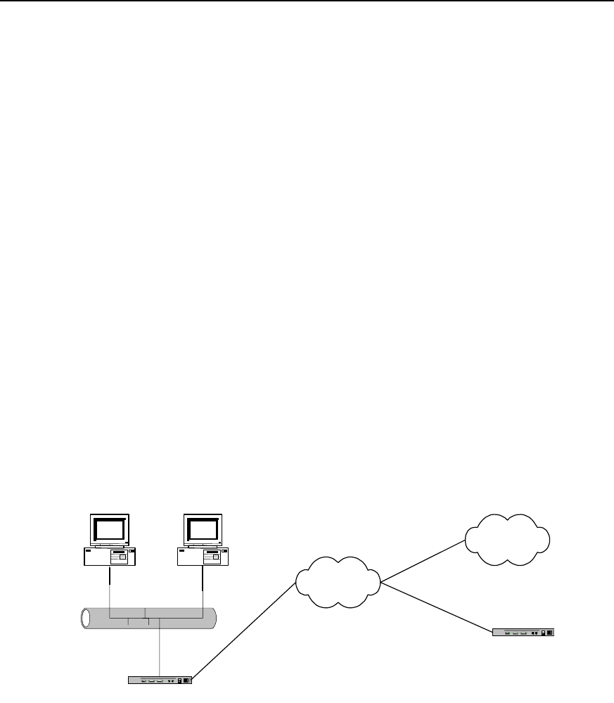
User Manual - Configuration Guide (Volume 3)
Versatile Routing Platform Chapter 1
DDR Configuration
1-47
Quidway(config-if-Serial0:15)# dialer in-band
Quidway(config-if-Serial0:15)# dialer-group 1
Quidway(config-if-Serial0:15)# dialer map ip 2.2.2.2 660368
Quidway(config-if-Serial0:15)# dialer map ip 2.2.2.2 660378
Quidway(config-if-Serial0:15)# ppp authentication pap
Quidway(config-if-Serial0:15)# ppp pap sent-username userb password 0 passb
1.6.9 B Channels for Dial-up and Connection to the Remote End - Case 2
Case 2: DDR in which one B channel in ISDN BRI interface is used for dial connection
to the remote end and the other for dedicated connection to the remote end.
Using one of the B channels of ISDN BRI interface for dial-up, the other one for remote
dial-up connection.
I. Networking requirements
DDR is the implementation solution. As shown in the following diagram, router A can
dial-up and dial to router B at the same time. We assume user access Internet with 163
Special Service number (user name: user163, password: pass163).
II. Networking diagram
Ethernet
Router A
ISDN
163
Router B
8810163
Internet
PC A PC B
8810148
Figure DC-1-11 Networking diagram of DDR – Case 2
III. Configuration procedure
Solution: use Dialer Profile to realize:
1) Configure router A:
Quidway(config)# access-list 1 deny any
Quidway(config)# access-list 1 permit 10.110.10.0 0.0.0.255
Quidway(config)# nat pool 202.110.10.10 202.110.10.11 pool 1
Quidway(config)# dialer-list 1 protocol ip permit

User Manual - Configuration Guide (Volume 3)
Versatile Routing Platform Chapter 1
DDR Configuration
1-48
Quidway(config)# user userb password 0 passb
Quidway(config)# interface dialer 0
Quidway(config-if-Dialer0)# ip address 100.1.1.1 255.255.255.0
Quidway(config-if-Dialer0)# dialer remote-name userb
Quidway(config-if-Dialer0)# dialer-group 1
Quidway(config-if-Dialer0)# ppp pap sent-username usera password 0 passa
Quidway(config-if-Dialer0)# dialer pool 1
Quidway(config-if-Dialer0)# dialer string 8810163
Quidway(config-if-Dialer0)# interface dialer 1
Quidway(config-if-Dialer1)# ip address negotiate
Quidway(config-if-Dialer1)# nat inside 1 pool 1
Quidway(config-if-Dialer1)# dialer remote-name userc
Quidway(config-if-Dialer1)# dialer-group 1
Quidway(config-if-Dialer1)# ppp pap sent-username user163 password 0 pass163
Quidway(config-if-Dialer1)# dialer pool 2
Quidway(config-if-Dialer1)# dialer string 163
Quidway(config-if-Dialer1)# interface bri 0
Quidway(config-if-Bri0)# no dialer in-band
Quidway(config-if-Bri0)# dialer pool-member 1
Quidway(config-if-Bri0)# dialer pool-member 2
Quidway(config-if-Bri0)# encapsulation ppp
Quidway(config-if-Bri0)# ppp authentication pap
2) Configure router B:
Quidway(config)# dialer-list 1 protocol ip permit
Quidway(config)# user usera password 0 passa
Quidway(config)# interface dialer 0
Quidway(config-if-Dialer0)# ip address 100.1.1.2 255.255.255.0
Quidway(config-if-Dialer0)# dialer remote-name usera
Quidway(config-if-Dialer0)# dialer string 8810148
Quidway(config-if-Dialer0)# dialer-group 1
Quidway(config-if-Dialer0)# dialer pool 1
Quidway(config-if-Dialer0)# ppp pap sent-username userb password 0 passb
Quidway(config-if-Dialer0)# interface bri 0
Quidway(config-if-Bri0)# no dialer in-band
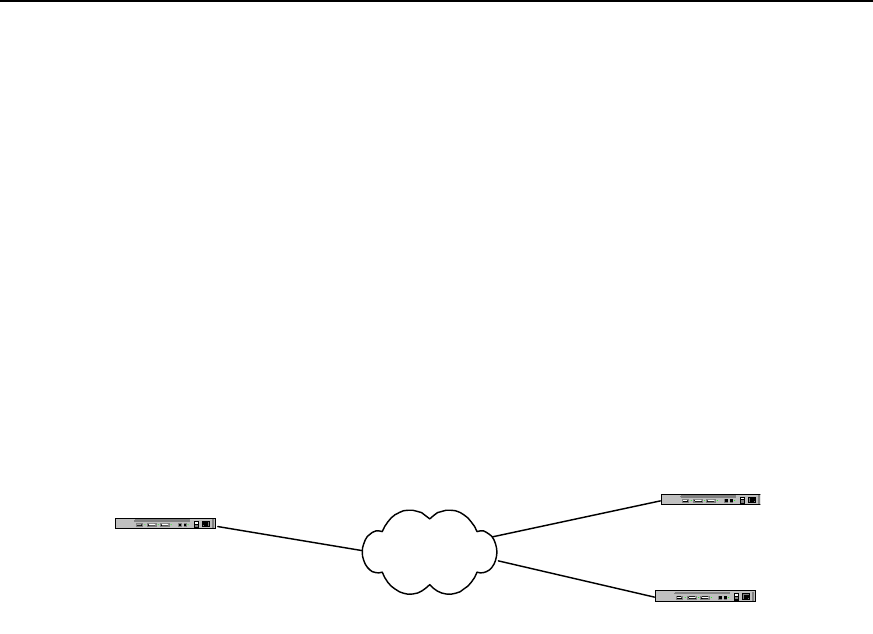
User Manual - Configuration Guide (Volume 3)
Versatile Routing Platform Chapter 1
DDR Configuration
1-49
Quidway(config-if-Bri0)# dialer pool-member 1
Quidway(config-if-Bri0)# encapsulation ppp
Quidway(config-if-Bri0)# ppp authentication pap
1.6.10 Two Serial Ports for Dial-up and Remote Dial Connection – Case 3
Case 3: DDR in which one serial port is used for dial access to Internet and another for
remote dial connection.
I. Networking requirements
One of the two B channels of ISDN BRI can be used for private line and the other for
dial-up. As shown in the following diagram, router A and router B are interconnected
with one B channel, the other B channel dial to router B.
II. Networking diagram
Router A ISDN
Router B
8810152
8810148
Router C
Figure DC-1-12 Networking diagram of DDR – Case 3
III. Configuration procedure
Solution: use Legacy DDR configuration to realize:
1) Configure router A:
Quidway(config)# dialer-list 1 protocol ip permit
Quidway(config)# interface bri 0
Quidway(config-if-Bri0)# ip address 100.1.1.1 255.255.255.0
Quidway(config-if-Bri0)# dialer isdn-leased 1
Quidway(config-if-Bri0)# dialer-group 1
Quidway(config-if-Bri0)# dialer map ip 100.1.1.2 8810152
Quidway(config-if-Bri0)# dialer map ip 100.1.1.3
2) Configure router B:
Quidway(config)# dialer-list 1 protocol ip permit
Quidway(config)# interface bri 0
Quidway(config-if-Bri0)# ip address 100.1.1.2 255.255.255.0
Quidway(config-if-Bri0)# dialer-group 1
Quidway(config-if-Bri0)# dialer map ip 100.1.1.1 8810148
3) Configure router C:
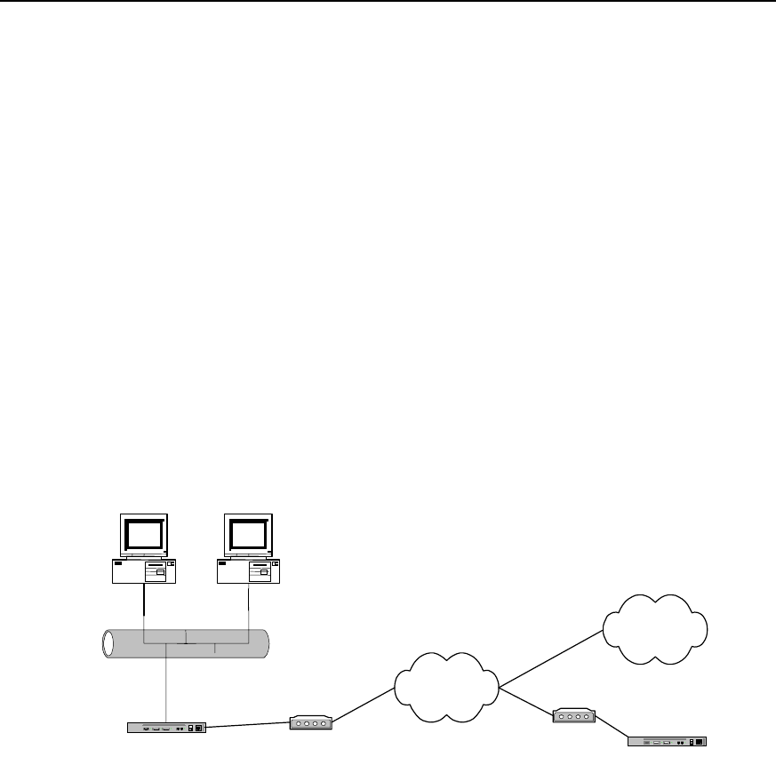
User Manual - Configuration Guide (Volume 3)
Versatile Routing Platform Chapter 1
DDR Configuration
1-50
Quidway(config)# dialer-list 1 protocol ip permit
Quidway(config)# interface bri 0
Quidway(config-if-Bri0)# ip address 100.1.1.3 255.255.255.0
Quidway(config-if-Bri0)# dialer isdn-leased 1
Quidway(config-if-Bri0)# dialer-group 1
Quidway(config-if-Bri0)# dialer map ip 100.1.1.1
1.6.11 One Serial Port for Dial-up and Remote Dial Connection – Case 4
Case 4: DDR in which one serial port is used both for dial access to Internet and for
remote dial connection.
I. networking requirements
Using Dialer Profile, we can configure a serial port to dial-up and dial to the remote end.
As shown in the following diagram, router A can dial-up and dial to router B at the same
time. We assume user access Internet with 163 Special Service number (user name:
user163, password: pass163).
Ethernet
Router A
PSTN
Modem Router B
Modem
163
8810048
PC A PC B
Internet
8810052
Figure DC-1-13 Networking diagram of DDR – Case 4
Solution: use Dialer Profile configuration to realize:
1) Configure router A
Quidway(config)# access-list 1 deny any
Quidway(config)# access-list 1 permit 10.110.10.0 0.0.0.255
Quidway(config)# nat pool 202.110.10.10 202.110.10.11 pool 1
Quidway(config)# dialer-list 1 protocol ip permit
Quidway(config)# user userb password 0 passb
Quidway(config)# interface dialer 0
Quidway(config-if-Dialer0)# ip address 100.1.1.1 255.255.255.0
Quidway(config-if-Dialer0)# dialer remote-name userb

User Manual - Configuration Guide (Volume 3)
Versatile Routing Platform Chapter 1
DDR Configuration
1-51
Quidway(config-if-Dialer0)# dialer-group 1
Quidway(config-if-Dialer0)# ppp pap sent-username usera password 0 passa
Quidway(config-if-Dialer0)# dialer pool 1
Quidway(config-if-Dialer0)# dialer string 8810048
Quidway(config-if-Dialer0)# interface dialer 1
Quidway(config-if-Dialer1)# ip address negotiate
Quidway(config-if-Dialer1)# nat inside 1 pool 1
Quidway(config-if-Dialer1)# dialer remote-name userc
Quidway(config-if-Dialer1)# dialer-group 1
Quidway(config-if-Dialer1)# ppp pap sent-username user163 password 0 pass163
Quidway(config-if-Dialer1)# dialer pool 2
Quidway(config-if-Dialer1)# dialer string 163
Quidway(config-if-Dialer1)# interface serial 0
Quidway(config-if-Serial0)# physical-layer async
Quidway(config-if-Serial0)# modem
Quidway(config-if-Serial0)# dialer pool-member 1
Quidway(config-if-Serial0)# dialer pool-member 2
Quidway(config-if-Serial0)# encapsulation ppp
Quidway(config-if-Serial0)# ppp authentication pap
2) Configure router B
Quidway(config)# dialer-list 1 protocol ip permit
Quidway(config)# user usera password 0 passa
Quidway(config)# interface dialer 0
Quidway(config-if-Dialer0)# ip address 100.1.1.2 255.255.255.0
Quidway(config-if-Dialer0)# dialer remote-name usera
Quidway(config-if-Dialer0)# dialer string 8810052
Quidway(config-if-Dialer0)# dialer-group 1
Quidway(config-if-Dialer0)# dialer pool 1
Quidway(config-if-Dialer0)# ppp pap sent-username userb password 0 passb
Quidway(config-if-Dialer0)# interface serial 0
Quidway(config-if-Serial0)# physical-layer async
Quidway(config-if-Serial0)# modem
Quidway(config-if-Serial0)# dialer pool-member 1
Quidway(config-if-Serial0)# encapsulation ppp
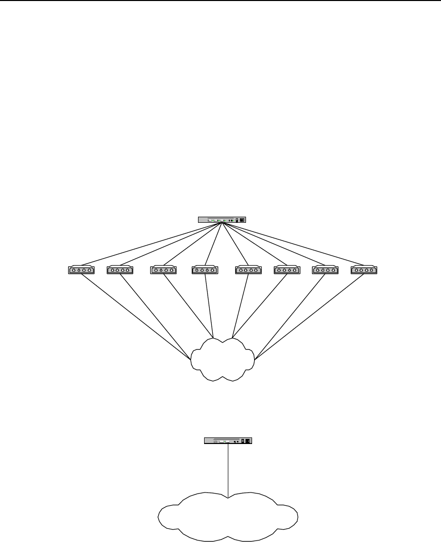
User Manual - Configuration Guide (Volume 3)
Versatile Routing Platform Chapter 1
DDR Configuration
1-52
Quidway(config-if-Serial0)# ppp authentication pap
1.6.12 DDR for Access Service
I. Networking requirements
We have designed the DDR implementation solution for access service by way of
asynchronous serial port and ISDN PRI interface. Here, it is supposed that the dial
string resources obtained by users from the telecom office are 8810048-8810055 and
8810148 respectively, serving 16 Internet users. In the configuration command, use
Serial2:15 to identify ISDN PRI interface created at cE1/PRI interface.
II. Networking diagram
Router A
PSTN
8810048 Modem
Modem
Modem
Modem Modem
Modem Modem Modem
8810055
8810054
8810053
8810052
8810051
88100508810049
Router A
ISDN
8810148
Access service using ISDN PRI interface
Access service using
asynchronous serial port
Figure DC-1-15 Networking diagram of the configuration example of DDR for access service
III. Configuration procedure
Solution 1: use Legacy DDR configuration mode, PPP PAP authentication and 8
asynchronous serial ports to realize:
Configure router A:

User Manual - Configuration Guide (Volume 3)
Versatile Routing Platform Chapter 1
DDR Configuration
1-53
Quidway(config)# dialer-list 1 protocol ip permit
Quidway(config)# user user1 password 0 pass1
Quidway(config)# user user2 password 0 pass2
Quidway(config)# user user3 password 0 pass3
Quidway(config)# user user4 password 0 pass4
Quidway(config)# user user5 password 0 pass5
Quidway(config)# user user6 password 0 pass6
Quidway(config)# user user7 password 0 pass7
Quidway(config)# user user8 password 0 pass8
Quidway(config)# user user9 password 0 pass9
Quidway(config)# user user10 password 0 pass10
Quidway(config)# user user11 password 0 pass11
Quidway(config)# user user12 password 0 pass12
Quidway(config)# user user13 password 0 pass13
Quidway(config)# user user14 password 0 pass14
Quidway(config)# user user15 password 0 pass15
Quidway(config)# user user16 password 0 pass16
Quidway(config)# ip local pool 1 100.1.1.1 100.1.1.16
Quidway(config)# interface dialer 0
Quidway(config-if-Dialer0)# ip address 100.1.1.254 255.255.255.0
Quidway(config-if-Dialer0)# peer default ip address pool 1
Quidway(config-if-Dialer0)# dialer in-band
Quidway(config-if-Dialer0)# dialer-group 1
Quidway(config-if-Dialer0)# encapsulation ppp
Quidway(config-if-Dialer0)# ppp authentication pap
Quidway(config-if-Dialer0)# interface async 1
Quidway(config-if-Async1)# dialer rotary-group 0
Quidway(config-if-Async1)# interface async 2
Quidway(config-if-Async2)# dialer rotary-group 0
Quidway(config-if-Async2)# interface async 3
Quidway(config-if-Async3)# dialer rotary-group 0
Quidway(config-if-Async3)# interface async 4
Quidway(config-if-Async4)# dialer rotary-group 0

User Manual - Configuration Guide (Volume 3)
Versatile Routing Platform Chapter 1
DDR Configuration
1-54
Quidway(config-if-Async4)# interface async 5
Quidway(config-if-Async5)# dialer rotary-group 0
Quidway(config-if-Async5)# interface async 6
Quidway(config-if-Async6)# dialer rotary-group 0
Quidway(config-if-Async6)# interface async 7
Quidway(config-if-Async7)# dialer rotary-group 0
Quidway(config-if-Async7)# interface async 8
Quidway(config-if-Async8)# dialer rotary-group 0
Solution 2: use Legacy DDR configuration mode, PPP CHAP authentication and 8
asynchronous serial ports to realize:
Configure router A:
Quidway(config)# dialer-list 1 protocol ip permit
Quidway(config)# user user1 password 0 pass1
Quidway(config)# user user2 password 0 pass2
Quidway(config)# user user3 password 0 pass3
Quidway(config)# user user4 password 0 pass4
Quidway(config)# user user5 password 0 pass5
Quidway(config)# user user6 password 0 pass6
Quidway(config)# user user7 password 0 pass7
Quidway(config)# user user8 password 0 pass8
Quidway(config)# user user9 password 0 pass9
Quidway(config)# user user10 password 0 pass10
Quidway(config)# user user11 password 0 pass11
Quidway(config)# user user12 password 0 pass12
Quidway(config)# user user13 password 0 pass13
Quidway(config)# user user14 password 0 pass14
Quidway(config)# user user15 password 0 pass15
Quidway(config)# user user16 password 0 pass16
Quidway(config)# ip local pool 1 100.1.1.1 100.1.1.16
Quidway(config)# interface dialer 0
Quidway(config-if-Dialer0)# ip address 100.1.1.254 255.255.255.0
Quidway(config-if-Dialer0)# peer default ip address pool 1
Quidway(config-if-Dialer0)# dialer in-band
Quidway(config-if-Dialer0)# dialer-group 1

User Manual - Configuration Guide (Volume 3)
Versatile Routing Platform Chapter 1
DDR Configuration
1-55
Quidway(config-if-Dialer0)# encapsulation ppp
Quidway(config-if-Dialer0)# ppp authentication chap
Quidway(config-if-Dialer0)# interface async 1
Quidway(config-if-Async1)# dialer rotary-group 0
Quidway(config-if-Async1)# interface async 2
Quidway(config-if-Async2)# dialer rotary-group 0
Quidway(config-if-Async2)# interface async 3
Quidway(config-if-Async3)# dialer rotary-group 0
Quidway(config-if-Async3)# interface async 4
Quidway(config-if-Async4)# dialer rotary-group 0
Quidway(config-if-Async4)# interface async 5
Quidway(config-if-Async5)# dialer rotary-group 0
Quidway(config-if-Async5)# interface async 6
Quidway(config-if-Async6)# dialer rotary-group 0
Quidway(config-if-Async6)# interface async 7
Quidway(config-if-Async7)# dialer rotary-group 0
Quidway(config-if-Async7)# interface async 8
Quidway(config-if-Async8)# dialer rotary-group 0
Solution 3: use Legacy DDR configuration mode and PPP PAP authentication to realize
the following at ISDN PRI interface:
Configure router A:
Quidway(config)# dialer-list 1 protocol ip permit
Quidway(config)# user user1 password 0 pass1
Quidway(config)# user user2 password 0 pass2
Quidway(config)# user user3 password 0 pass3
Quidway(config)# user user4 password 0 pass4
Quidway(config)# user user5 password 0 pass5
Quidway(config)# user user6 password 0 pass6
Quidway(config)# user user7 password 0 pass7
Quidway(config)# user user8 password 0 pass8
Quidway(config)# user user9 password 0 pass9
Quidway(config)# user user10 password 0 pass10
Quidway(config)# user user11 password 0 pass11
Quidway(config)# user user12 password 0 pass12

User Manual - Configuration Guide (Volume 3)
Versatile Routing Platform Chapter 1
DDR Configuration
1-56
Quidway(config)# user user13 password 0 pass13
Quidway(config)# user user14 password 0 pass14
Quidway(config)# user user15 password 0 pass15
Quidway(config)# user user16 password 0 pass16
Quidway(config)# ip local pool 1 100.1.1.1 100.1.1.16
Quidway(config)# interface serial2:15
Quidway(config-if-Serial2:15)# ip address 100.1.1.254 255.255.255.0
Quidway(config-if-Serial2:15)# peer default ip address pool 1
Quidway(config-if-Serial2:15)# dialer-group 1
Quidway(config-if-Serial2:15)# encapsulation ppp
Quidway(config-if-Serial2:15)# ppp authentication pap
Solution 4: use Legacy DDR configuration mode and PPP CHAP authentication to
realize the following at ISDN PRI interface:
Configure router A:
Quidway(config)# dialer-list 1 protocol ip permit
Quidway(config)# user user1 password 0 pass1
Quidway(config)# user user2 password 0 pass2
Quidway(config)# user user3 password 0 pass3
Quidway(config)# user user4 password 0 pass4
Quidway(config)# user user5 password 0 pass5
Quidway(config)# user user6 password 0 pass6
Quidway(config)# user user7 password 0 pass7
Quidway(config)# user user8 password 0 pass8
Quidway(config)# user user9 password 0 pass9
Quidway(config)# user user10 password 0 pass10
Quidway(config)# user user11 password 0 pass11
Quidway(config)# user user12 password 0 pass12
Quidway(config)# user user13 password 0 pass13
Quidway(config)# user user14 password 0 pass14
Quidway(config)# user user15 password 0 pass15
Quidway(config)# user user16 password 0 pass16
Quidway(config)# ip local pool 1 100.1.1.1 100.1.1.16
Quidway(config)# interface serial2:15
Quidway(config-if-Serial2:15)# ip address 100.1.1.254 255.255.255.0
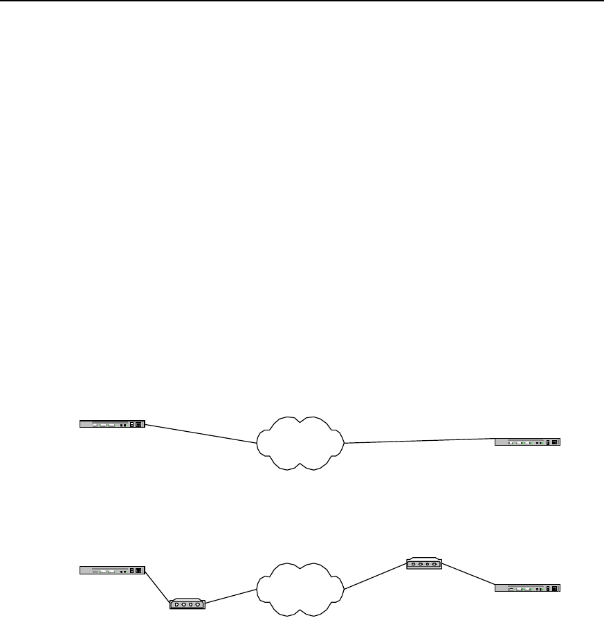
User Manual - Configuration Guide (Volume 3)
Versatile Routing Platform Chapter 1
DDR Configuration
1-57
Quidway(config-if-Serial2:15)# peer default ip address pool 1
Quidway(config-if-Serial2:15)# dialer-group 1
Quidway(config-if-Serial2:15)# encapsulation ppp
Quidway(config-if-Serial2:15)# ppp authentication chap
1.6.13 DDR for Inter-Router Callback
I. Networking requirements
We have designed two implementation solutions: “use ISDN calling line identification
callback” and “Use PPP callback”. In the implementation solution “use ISDN calling line
identification callback”, routers at both ends need to use ISDN interface for
interconnection. In the following configuration procedure, Bri 0 is used to identify ISDN
interface, router A is used as callback Server end and router B as callback Client end.
“ISDN calling line identification callback” and “PPP callback” can be used in
combination, and users can simply combine the configuration procedures of the two
listed below:
II. Networking diagram
Router A PSTN
Modem
Router B
Modem
8810052
Networking diagram of
PPP callback
8810048
Router A ISDN Router B
8810152
8810148
Networking diagram of ISDN
caller identifying callback
Figure DC-1-16 Networking diagram of inter-router callback DDR configuration example
III. Configuration procedure
Solution 1: use ISDN calling line identification callback
1) Configure router A:
Quidway(config)# dialer-list 1 protocol ip permit
Quidway(config)# interface bri 0
Quidway(config-if-Bri0)# ip address 100.1.1.1 255.255.255.0
Quidway(config-if-Bri0)# dialer-group 1
Quidway(config-if-Bri0)# dialer map ip 100.1.1.2 8810152

User Manual - Configuration Guide (Volume 3)
Versatile Routing Platform Chapter 1
DDR Configuration
1-58
Quidway(config-if-Bri0)# dialer caller 8810152 callback
3) Configure router B:
Quidway(config)# dialer-list 1 protocol ip permit
Quidway(config)# interface bri 0
Quidway(config-if-Bri0)# ip address 100.1.1.2 255.255.255.0
Quidway(config-if-Bri0)# dialer-group 1
Quidway(config-if-Bri0)# dialer map ip 100.1.1.1 8810148
Solution 2: use PPP callback and Server end uses user-configured dialer map for
callback
1) Configure router A:
Quidway(config)# dialer-list 1 protocol ip permit
Quidway(config)# user quidwayb password 0 quidwayb
Quidway(config)# interface serial 0
Quidway(config-if-Serial0)# ip address 100.1.1.1 255.255.255.0
Quidway(config-if-Serial0)# physical-layer async
Quidway(config-if-Serial0)# modem
Quidway(config-if-Serial0)# dialer in-band
Quidway(config-if-Serial0)# dialer-group 1
Quidway(config-if-Serial0)# dialer map ip 100.1.1.2 name quidwayb 8810052
Quidway(config-if-Serial0)# dialer callback-server username
Quidway(config-if-Serial0)# ppp authentication pap
Quidway(config-if-Serial0)# ppp callback accept
4) Configure router B:
Quidway(config)# dialer-list 1 protocol ip permit
Quidway(config)# interface serial 0
Quidway(config-if-Serial0)# ip address 100.1.1.2 255.255.255.0
Quidway(config-if-Serial0)# physical-layer async
Quidway(config-if-Serial0)# modem
Quidway(config-if-Serial0)# dialer in-band
Quidway(config-if-Serial0)# dialer-group 1
Quidway(config-if-Serial0)# dialer map ip 100.1.1.1 8810048
Quidway(config-if-Serial0)# ppp pap sent-username quidwayb password 0 quidwayb
Quidway(config-if-Serial0)# ppp callback request
Solution 3: use PPP callback and Server end dynamically creates dialer map for
callback
1) Configure router A:

User Manual - Configuration Guide (Volume 3)
Versatile Routing Platform Chapter 1
DDR Configuration
1-59
Quidway(config)# dialer-list 1 protocol ip permit
Quidway(config)# user quidwayb password 0 quidwayb callback-dialstring 8810052
Quidway(config)# interface serial 0
Quidway(config-if-Serial0)# ip address 100.1.1.1 255.255.255.0
Quidway(config-if-Serial0)# physical-layer async
Quidway(config-if-Serial0)# modem
Quidway(config-if-Serial0)# dialer in-band
Quidway(config-if-Serial0)# dialer-group 1
Quidway(config-if-Serial0)# dialer callback-server dialstring
Quidway(config-if-Serial0)# ppp authentication pap
Quidway(config-if-Serial0)# ppp callback accept
2) Configure router B:
Quidway(config)# dialer-list 1 protocol ip permit
Quidway(config)# interface serial 0
Quidway(config-if-Serial0)# ip address 100.1.1.2 255.255.255.0
Quidway(config-if-Serial0)# physical-layer async
Quidway(config-if-Serial0)# modem
Quidway(config-if-Serial0)# dialer in-band
Quidway(config-if-Serial0)# dialer-group 1
Quidway(config-if-Serial0)# dialer map ip 100.1.1.1 8810048
Quidway(config-if-Serial0)# ppp pap sent-username quidwayb password 0 quidwayb
Quidway(config-if-Serial0)# ppp callback request
1.6.14 DDR in Which the Router Calls Back PC
I. Networking requirements
We have designed two implementation solutions: “use user-configured dialer map for
callback” and “dynamically create dialer map for callback”. In both solutions, routers are
used to allocate IP addresses for PCs.
II. Networking diagram
Router A PSTN
Modem
Modem
8810052
8810048
PC
Figure DC-1-17 Networking diagram of DDR configuration example in which routers call back PCs

User Manual - Configuration Guide (Volume 3)
Versatile Routing Platform Chapter 1
DDR Configuration
1-60
III. Configuration procedure
Solution 1: using user-configured dialer map for callback, with router A serving as
server end.
1) Configure router A:
Quidway(config)# dialer-list 1 protocol ip permit
Quidway(config)# user pc password 0 pc
Quidway(config)# interface serial 0
Quidway(config-if-Serial0)# ip address 100.1.1.1 255.255.255.0
Quidway(config-if-Serial0)# peer default ip address 100.1.1.2
Quidway(config-if-Serial0)# physical-layer async
Quidway(config-if-Serial0)# modem
Quidway(config-if-Serial0)# dialer in-band
Quidway(config-if-Serial0)# dialer-group 1
Quidway(config-if-Serial0)# dialer map ip 100.1.1.2 name pc 8810052
Quidway(config-if-Serial0)# dialer callback-server username
Quidway(config-if-Serial0)# ppp authentication pap
Quidway(config-if-Serial0)# ppp pap sent-username quidway password 0 quidway
Quidway(config-if-Serial0)# ppp callback accept
2) Configure PC:
a. Configure Modem connected to PC end to “automatic answering mode”;
b. Click: Start->Programs->Accessories->Communications->Dialup network;
c. In “Dialup network” window, select “Set up new connection”;
d. In “My connection” established, select “TCP/IP setting”, in which:
z Select “Server allocated with IP address”;
z Cancel “Use IP head pointer compression”;
z Cancel “Use default gateway of the remote network”;
e. In “My connection” established, select “Server type”, in which:
z Select “ppp”;
z Cancel “Logon network”;
z Cancel “Start software compression”.
Solution 2: Dynamically creating dialer map for callback, with router A as Server end
1) Configure router A:
Quidway(config)# dialer-list 1 protocol ip permit
Quidway(config)# user pc password 0 pc callback-dialstring 8810052
Quidway(config)# interface serial 0
Quidway(config-if-Serial0)# ip address 100.1.1.1 255.255.255.0
Quidway(config-if-Serial0)# peer default ip address 100.1.1.2

User Manual - Configuration Guide (Volume 3)
Versatile Routing Platform Chapter 1
DDR Configuration
1-61
Quidway(config-if-Serial0)# physical-layer async
Quidway(config-if-Serial0)# modem
Quidway(config-if-Serial0)# dialer in-band
Quidway(config-if-Serial0)# dialer-group 1
Quidway(config-if-Serial0)# dialer callback-server dialstring
Quidway(config-if-Serial0)# ppp authentication pap
Quidway(config-if-Serial0)# ppp pap sent-username quidway password 0 quidway
Quidway(config-if-Serial0)# ppp callback accept
2) Configure PC:
a. Configure Modem connected to PC end to “automatic answering mode”;
b. Click: Start->Programs->Accessories->Communications->Dialup network;
c. In “Dialup network” window, select “Set up new connection”;
d. In “My connection” established, select “TCP/IP setting”, in which:
z Select “Server allocated with IP address”;
z Cancel “Use IP head pointer compression”;
z Cancel “Use default gateway of the remote network”;
e. In “My connection” established, select “Server type”, in which:
z Select “ppp”;
z Cancel “Logon network”;
z Cancel “Start software compression”.
1.6.15 DDR for Autodial
I. Networking requirements
We have designed point-to-point autodial configuration solution. Point-to-multipoint
and multipoint-to-multipoint autodial can be configured in a similar way. In the following
diagram, router A automatically dials to call router B at an interval of 180 seconds.
II. Networking diagram
Router A PSTN
Modem Router B
Modem
8810052
8810048
Figure DC-1-18 Networking diagram of the configuration example of DDR for autodial
III. Configuration procedure
1) Configure router A:
Quidway(config)# dialer-list 1 protocol ip permit
Quidway(config)# interface serial 0

User Manual - Configuration Guide (Volume 3)
Versatile Routing Platform Chapter 1
DDR Configuration
1-62
Quidway(config-if-Serial0)# ip address 100.1.1.1 255.255.255.0
Quidway(config-if-Serial0)# physical-layer async
Quidway(config-if-Serial0)# modem
Quidway(config-if-Serial0)# dialer in-band
Quidway(config-if-Serial0)# dialer-group 1
Quidway(config-if-Serial0)# dialer map ip 100.1.1.2 8810052 autodial
Quidway(config-if-Serial0)# dialer autodial-interval 180
2) Configure router B:
Quidway(config)# dialer-list 1 protocol ip permit
Quidway(config)# interface serial 0
Quidway(config-if-Serial0)# ip address 100.1.1.2 255.255.255.0
Quidway(config-if-Serial0)# physical-layer async
Quidway(config-if-Serial0)# modem
Quidway(config-if-Serial0)# dialer in-band
Quidway(config-if-Serial0)# dialer-group 1
1.6.16 DDR Using Dialer Map Cyclically
I. Networking requirements
We have designed two routers to use dialer map cyclically. In the following networking
diagram, router A calls router B.
II. Networking diagram
Router A PSTN
Modem 8810052
8810048 Router B
Modem
Modem
8810060
Figure DC-1-19 Networking diagram of the configuration example of DDR using dialer map cyclically
III. Configuration procedure
1) Configure router A:
Quidway(config)# dialer-list 1 protocol ip permit
Quidway(config)# interface serial 0
Quidway(config-if-Serial0)# physical-layer async
Quidway(config-if-Serial0)# modem
Quidway(config-if-Serial0)# ip address 100.1.1.1 255.255.255.0

User Manual - Configuration Guide (Volume 3)
Versatile Routing Platform Chapter 1
DDR Configuration
1-63
Quidway(config-if-Serial0)# dialer in-band
Quidway(config-if-Serial0)# dialer-group 1
Quidway(config-if-Serial0)# dialer map ip 100.1.1.2 8810052
Quidway(config-if-Serial0)# dialer map ip 100.1.1.2 8810060
2) Configure router B:
Quidway(config)# dialer-list 1 protocol ip permit
Quidway(config)# interface dialer 0
Quidway(config-if-Dialer0)# ip address 100.1.1.2 255.255.255.0
Quidway(config-if-Dialer0)# dialer in-band
Quidway(config-if-Dialer0)# dialer-group 1
Quidway(config-if-Dialer0)# interface serial 0
Quidway(config-if-Serial0)# physical-layer async
Quidway(config-if-Serial0)# modem
Quidway(config-if-Serial0)# dialer rotary-group 0
Quidway(config-if-Serial0)# interface serial 1
Quidway(config-if-Serial1)# physical-layer async
Quidway(config-if-Serial1)# modem
Quidway(config-if-Serial1)# dialer rotary-group 0
1.6.17 DDR Using Dialer Map as Backup
I. Networking requirements
We have designed two configurations in which the logical interface designed by dialer
map is used as backup interface and as main interface. In the following diagram, we
have configured backup in router A. s0 port of router A is configured as dial port, and s1
port is configured as DDN directly connected port of encapsulation PPP.
II. Networking diagram
Router A PSTN
Modem 8810052
8810048
8810060
Router B
Modem
Modem
Figure DC-1-20 Networking diagram of the configuration example of DDR with dialer map as backup
III. Configuration procedure
Solution 1: Logical interface as backup interface

User Manual - Configuration Guide (Volume 3)
Versatile Routing Platform Chapter 1
DDR Configuration
1-64
1) Configure router A:
Quidway(config)# dialer-list 1 protocol ip permit
Quidway(config)# interface serial 0
Quidway(config-if-Serial0)# ip address 100.1.1.1 255.255.255.0
Quidway(config-if-Serial0)# physical-layer async
Quidway(config-if-Serial0)# modem
Quidway(config-if-Serial0)# dialer in-band
Quidway(config-if-Serial0)# dialer-group 1
Quidway(config-if-Serial0)# dialer map ip 100.1.1.2 8810060 lin 1
Quidway(config-if-Serial0)# interface serial 1
Quidway(config-if-Serial1)# ip address 200.1.1.1 255.255.255.0
Quidway(config-if-Serial1)# encapsulation ppp
Quidway(config-if-Serial1)# backup logic-channel 1
2) Configure router B:
Quidway(config)# dialer-list 1 protocol ip permit
Quidway(config)# interface serial 0
Quidway(config-if-Serial0)# ip address 100.1.1.2 255.255.255.0
Quidway(config-if-Serial0)# physical-layer async
Quidway(config-if-Serial0)# modem
Quidway(config-if-Serial0)# dialer in-band
Quidway(config-if-Serial0)# dialer-group 1
Quidway(config-if-Serial0)# interface serial 1
Quidway(config-if-Serial1)# ip address 200.1.1.2 255.255.255.0
Quidway(config-if-Serial1)# encapsulation ppp
Solution 2: Logical interface as main interface
1) Configure router A:
Quidway(config)# dialer-list 1 protocol ip permit
Quidway(config)# interface serial 0
Quidway(config-if-Serial0)# ip address 100.1.1.1 255.255.255.0
Quidway(config-if-Serial0)# physical-layer async
Quidway(config-if-Serial0)# modem
Quidway(config-if-Serial0)# dialer in-band
Quidway(config-if-Serial0)# dialer-group 1
Quidway(config-if-Serial0)# dialer map ip 100.1.1.2 8810060 lin 1

User Manual - Configuration Guide (Volume 3)
Versatile Routing Platform Chapter 1
DDR Configuration
1-65
Quidway(config-if-Serial0)# exit
Quidway(config)# logic-channel 1
Quidway(config-logic-channel1)# backup interface serial 1
Quidway(config-logic-channel1)# exit
Quidway(config)# interface serial 1
Quidway(config-if-Serial1)# ip address 200.1.1.1 255.255.255.0
Quidway(config-if-Serial1)# encapsulation ppp
2) Configure router B:
Quidway(config)# dialer-list 1 protocol ip permit
Quidway(config)# interface serial 0
Quidway(config-if-Serial0)# ip address 100.1.1.2 255.255.255.0
Quidway(config-if-Serial0)# physical-layer asynct
Quidway(config-if-Serial0)# modem
Quidway(config-if-Serial0)# dialer in-band
Quidway(config-if-Serial0)# dialer-group 1
Quidway(config-if-Serial0)# interface serial 1
Quidway(config-if-Serial1)# ip address 200.1.1.2 255.255.255.0
Quidway(config-if-Serial1)# encapsulation ppp
1.7 Precautions for DDR Configuration
1.7.1 Configuring Dialer-group
Dialer-group must be configured at the logic dial interface or at the physical interface
that directly enables DDR, and dialer-group must correspond to dialer-list configured in
global configuration status, as shown in the following bold-typed parts.
Quidway(config)# dialer-list 1 protocol ip permit
Quidway(config)# dialer-list 1 protocol ipx permit
Quidway(config)# interface dialer 0
Quidway(config-if-Dialer0)# dialer in-band
Quidway(config-if-Dialer0)# dialer-group 1
1.7.2 Configuring Synchronous/Asynchronous Serial Port Using DDR
To make synchronous/asynchronous serial port visible and perform DDR configuration
on it, it is necessary to execute two configuration commands, physical-layer async and
modem, and enable DDR command, as shown in the following bold-typed parts.

User Manual - Configuration Guide (Volume 3)
Versatile Routing Platform Chapter 1
DDR Configuration
1-66
Quidway(config)# interface serial 0
Quidway(config-if-Serial0)# physical-layer async
Quidway(config-if-Serial0)# modem
Quidway(config-if-Serial0)# dialer in-band
1.7.3 Configuring Network Layer Address
To enable network layer to find a route to the correct interface, network layer address
(such as IP address) must be configured at the logic dial interface or the physical
interface that directly enables DDR, as shown in the following bold-typed parts.
Example 1: in Legacy DDR configuration mode, the physical interface enables DDR by
being bound to the logic dial interface.
Quidway(config)# dialer-list 1 protocol ip permit
Quidway(config)# interface dialer 0
Quidway(config-if-Dialer0)# ip address 100.1.1.1 255.255.255.0
Quidway(config-if-Dialer0)# dialer in-band
Quidway(config-if-Dialer0)# dialer-group 1
Quidway(config-if-Dialer0)# dialer string 8810052
Quidway(config-if-Dialer0)# interface serial 0
Quidway(config-if-Serial0)# physical-layer async
Quidway(config-if-Serial0)# modem
Quidway(config-if-Serial0)# dialer rotary-group 0
Example 2: in Legacy DDR configuration mode, the physical interface directly enables
DDR.
Quidway(config)# dialer-list 1 protocol ip permit
Quidway(config)# interface serial 0
Quidway(config-if-Serial0)# physical-layer async
Quidway(config-if-Serial0)# modem
Quidway(config-if-Serial0)# ip address 100.1.1.1 255.255.255.0
Quidway(config-if-Serial0)# dialer in-band
Quidway(config-if-Serial0)# dialer-group 1
Quidway(config-if-Serial0)# dialer string 8810052
Example 3: Dialer Profile configuration mode
Quidway(config)# dialer-list 1 protocol ip permit
Quidway(config)# interface dialer 0
Quidway(config-if-Dialer0)# ip address 100.1.1.1 255.255.255.0

User Manual - Configuration Guide (Volume 3)
Versatile Routing Platform Chapter 1
DDR Configuration
1-67
Quidway(config-if-Dialer0)# dialer remote-name user1
Quidway(config-if-Dialer0)# dialer-group 1
Quidway(config-if-Dialer0)# dialer pool 1
Quidway(config-if-Dialer0)# dialer string 8810052
Quidway(config-if-Dialer0)# interface serial 0
Quidway(config-if-Serial0)# physical-layer async
Quidway(config-if-Serial0)# modem
Quidway(config-if-Serial0)# dialer pool-member 1
1.7.4 Configuring PPP In Dialer Profile Configuration Mode
In Dialer Profile configuration mode, if the local end needs to receive an incoming call,
PPP authentication must be configured at the local physical interface so as to
determine which dial interface the incoming call in oriented to.
There are two PPP authentication modes: PAP authentication and CHAP
authentication. With different PPP authentication modes, the desired configuration
commands and application modes are different, as detailed below:
The PPP configuration commands involved are:
z encapsulation ppp
z ppp authentication { pap | chap }
z ppp pap sent-username name password { 0 | 7 } password
z ppp chap host hostname
z user username password { 0 | 7 } password
I. Apply PAP authentication
With PAP name authentication mode, configuration must be performed according to
the following steps, in which name1 and pass1 can be replaced with specific character
strings selected by the users.
z Configure the remote user name of the local Dialer interface: dialer remote-name
name1
z Configure link layer protocol encapsulation of the local physical interface:
encapsulation ppp
z Configure PPP authentication mode: ppp authentication pap
z Configure the user name and password of the remote router: user name1
password 0 pass1
z Configure the user name and password sent by the local Dialer interface or the
physical interface directly enabling DDR during PAP authentication: ppp pap
sent-username name1 password 0 pass1
Example 1: apply serial port
1) Configure local router:
Quidway(config)# user remoteuser1 password 0 remotepass1
Quidway(config)# dialer-list 1 protocol ip permit
Quidway(config)# dialer-list 1 protocol ipx permit
Quidway(config)# interface dialer 0

User Manual - Configuration Guide (Volume 3)
Versatile Routing Platform Chapter 1
DDR Configuration
1-68
Quidway(config-if-Dialer0)# ip address 100.1.1.1 255.255.255.0
Quidway(config-if-Dialer0)# dialer remote-name remoteuser1
Quidway(config-if-Dialer0)# dialer-group 1
Quidway(config-if-Dialer0)# dialer-pool 1
Quidway(config-if-Dialer0)# dialer string 8810052
Quidway(config-if-Dialer0)# interface serial 0
Quidway(config-if-Serial0)# physical-layer async
Quidway(config-if-Serial0)# modem
Quidway(config-if-Serial0)# dialer pool-member 1
Quidway(config-if-Serial0)# encapsulation ppp
Quidway(config-if-Serial0)# ppp authentication pap
2) Configure remote router:
Quidway(config)# dialer-list 1 protocol ip permit
Quidway(config)# dialer-list 1 protocol ipx permit
Quidway(config)# interface serial 0
Quidway(config-if-Serial0)# ip address 100.1.1.2 255.255.255.0
Quidway(config-if-Serial0)# physical-layer async
Quidway(config-if-Serial0)# modem
Quidway(config-if-Serial0)# dialer in-band
Quidway(config-if-Serial0)# dialer string 8810048
Quidway(config-if-Serial0)# dialer-group 1
Quidway(config-if-Serial0)# encapsulation ppp
Quidway(config-if-Serial0)# ppp sent-username remoteuser1 password 0 remotepass1
Example 2: apply ISDN BRI and PRI interfaces
1) Configure local router:
Quidway(config)# user remoteuser1 password 0 remotepass1
Quidway(config)# dialer-list 1 protocol ip permit
Quidway(config)# dialer-list 1 protocol ipx permit
Quidway(config)# interface dialer 0
Quidway(config-if-Dialer0)# ip address 100.1.1.1 255.255.255.0
Quidway(config-if-Dialer0)# dialer remote-name remoteuser1
Quidway(config-if-Dialer0)# dialer-group 1
Quidway(config-if-Dialer0)# dialer-pool 1
Quidway(config-if-Dialer0)# dialer string 8810152

User Manual - Configuration Guide (Volume 3)
Versatile Routing Platform Chapter 1
DDR Configuration
1-69
Quidway(config-if-Dialer0)# interface bri 0
Quidway(config-if-Bri0)# no dialer in-band
Quidway(config-if-Bri0)# dialer pool-member 1
Quidway(config-if-Bri0)# encapsulation ppp
Quidway(config-if-Bri0)# ppp authentication pap
2) Configure remote router:
Quidway(config)# dialer-list 1 protocol ip permit
Quidway(config)# dialer-list 1 protocol ipx permit
Quidway(config)# interface bri 0
Quidway(config-if-Bri0)# ip address 100.1.1.2 255.255.255.0
Quidway(config-if-Bri0)# dialer string 8810048
Quidway(config-if-Bri0)# dialer-group 1
Quidway(config-if-Bri0)# encapsulation ppp
Quidway(config-if-Bri0)# ppp sent-username remoteuser1 password 0 remotepass1
II. Apply CHAP authentication
With CHAP authentication mode, configuration must be performed according to the
following steps, in which name1, name2 and pass1 can be replaced with specific
character strings selected by the users.
z Configure the remote user name of the local Dialer interface: dialer remote-name
name1
z Configure link layer protocol encapsulation of the local physical interface:
encapsulation ppp
z Configure PPP authentication mode: ppp authentication chap
z Configure local router name of CHAP authentication: ppp chap host name2
z Configure the user name and password of the remote router: user name1
password 0 pass1
z Configure the user name and password of the local router: user name2 password
0 pass1
z Configure remote router name at Dialer interface, or the physical interface directly
enabling DDR, of the remote router: ppp chap host name1
Example 1: apply serial port
1) Configure local router:
Quidway(config)# dialer-list 1 protocol ip permit
Quidway(config)# user remoteuser1 password 0 togetherpass
Quidway(config)# interface dialer 0
Quidway(config-if-Dialer0)# ip address 100.1.1.1 255.255.255.0
Quidway(config-if-Dialer0)# dialer remote-name remoteuser1
Quidway(config-if-Dialer0)# dialer-group 1
Quidway(config-if-Dialer0)# dialer pool 1

User Manual - Configuration Guide (Volume 3)
Versatile Routing Platform Chapter 1
DDR Configuration
1-70
Quidway(config-if-Dialer0)# dialer string 8810052
Quidway(config-if-Dialer0)# interface serial 0
Quidway(config-if-Serial0)# physical-layer async
Quidway(config-if-Serial0)# modem
Quidway(config-if-Serial0)# dialer pool-member 1
Quidway(config-if-Serial0)# encapsulation ppp
Quidway(config-if-Serial0)# ppp authentication chap
Quidway(config-if-Serial0)# ppp chap host localuser1
2) Configure remote router:
Quidway(config)# dialer-list 1 protocol ip permit
Quidway(config)# user localuser1 password 0 togetherpass
Quidway(config)# interface dialer 0
Quidway(config-if-Dialer0)# ip address 100.1.1.2 255.255.255.0
Quidway(config-if-Dialer0)# dialer in-band
Quidway(config-if-Dialer0)# dialer-group 1
Quidway(config-if-Dialer0)# dialer string 8810048
Quidway(config-if-Dialer0)# ppp chap host remoteuser1
Quidway(config-if-Dialer0)# interface serial 0
Quidway(config-if-Serial0)# physical-layer async
Quidway(config-if-Serial0)# modem
Quidway(config-if-Serial0)# dialer rotary-group 0
Example 2: apply ISDN BRI and PRI interfaces
1) Configure local router:
Quidway(config)# dialer-list 1 protocol ip permit
Quidway(config)# user remoteuser1 password 0 togetherpass
Quidway(config)# interface dialer 0
Quidway(config-if-Dialer0)# ip address 100.1.1.1 255.255.255.0
Quidway(config-if-Dialer0)# dialer remote-name remoteuser1
Quidway(config-if-Dialer0)# dialer-group 1
Quidway(config-if-Dialer0)# dialer pool 1
Quidway(config-if-Dialer0)# dialetr string 8810152
Quidway(config-if-Dialer0)# interface bri 0
Quidway(config-if-Bri0)# no dialer in-band
Quidway(config-if-Bri0)# dialer pool-member 1

User Manual - Configuration Guide (Volume 3)
Versatile Routing Platform Chapter 1
DDR Configuration
1-71
Quidway(config-if-Bri0)# encapsulation ppp
Quidway(config-if-Bri0)# ppp authentication chap
Quidway(config-if-Bri0)# ppp chap host localuser1
2) Configure remote router:
Quidway(config)# dialer-list 1 protocol ip permit
Quidway(config)# user localuser1 password 0 togetherpass
Quidway(config)# interface bri 0
Quidway(config-if-Bri0)# ip address 100.1.1.2 255.255.255.0
Quidway(config-if-Bri0)# dialer-group 1
Quidway(config-if-Bri0)# dialer string 8810048
Quidway(config-if-Bri0)# ppp chap host remoteuser1
1.7.5 Configuring PPP In Legacy DDR Configuration Mode
In Legacy DDR configuration mode, if the local end needs to receive an incoming call,
then, when name is configured in the local dialer map, PPP authentication must be
configured at the corresponding logic dial interface or the physical interface directly
enabling DDR, so as to obtain the remote user name for determining dialer map at the
local end.
There are two PPP authentication modes: PAP authentication and CHAP
authentication. With different PPP authentication modes, the desired configuration
commands and application modes are different, as detailed below:
The PPP configuration commands involved are:
z encapsulation
ppp
z ppp authentication { pap | chap }
z ppp pap sent-username name password { 0 | 7} password
z ppp chap host hostname
z user
username password { 0 | 7} password
I. Apply PAP authentication
With PAP name authentication mode, configuration must be performed according to
the following steps, in which name1 and pass1 can be replaced with specific character
strings selected by the users.
z Configure the remote user name of the local Dialer interface: dialer map protocol
next-hop-address name name1
z Configure link layer protocol encapsulation of the local physical interface:
encapsulation ppp
z Configure PPP authentication mode: ppp authentication pap
z Configure the user name and password of the remote router: user name1
password 0 pass1
z Configure the user name and password sent by the local Dialer interface or the
physical interface directly enabling DDR during PAP authentication: ppp pap
sent-username name1 password 0 pass1
Example 1: apply serial port
1) Configure local router:

User Manual - Configuration Guide (Volume 3)
Versatile Routing Platform Chapter 1
DDR Configuration
1-72
Quidway(config)# user remoteuser1 password 0 remotepass1
Quidway(config)# dialer-list 1 protocol ip permit
Quidway(config)# dialer-list 1 protocol ipx permit
Quidway(config)# interface dialer 0
Quidway(config-if-Dialer0)# ip address 100.1.1.1 255.255.255.0
Quidway(config-if-Dialer0)# dialer map ip 100.1.1.2 name remoteuser1 8810052
Quidway(config-if-Dialer0)# encapsulation ppp
Quidway(config-if-Dialer0)# ppp authentication pap
Quidway(config-if-Dialer0)# dialer-group 1
Quidway(config-if-Dialer0)# interface serial 0
Quidway(config-if-Serial0)# physical-layer async
Quidway(config-if-Serial0)# modem
Quidway(config-if-Serial0)# dialer rotary-group 0
2) Configure remote router:
Quidway(config)# dialer-list 1 protocol ip permit
Quidway(config)# dialer-list 1 protocol ipx permit
Quidway(config)# interface serial 0
Quidway(config-if-Serial0)# ip address 100.1.1.2 255.255.255.0
Quidway(config-if-Serial0)# physical-layer async
Quidway(config-if-Serial0)# modem
Quidway(config-if-Serial0)# dialer in-band
Quidway(config-if-Serial0)# dialer string 8810048
Quidway(config-if-Serial0)# dialer-group 1
Quidway(config-if-Serial0)# encapsulation ppp
Quidway(config-if-Serial0)# ppp sent-username remoteuser1 password 0 remotepass1
Example 2: apply ISDN BRI and PRI interfaces
1) Configure local router:
Quidway(config)# user remoteuser1 password 0 remotepass1
Quidway(config)# dialer-list 1 protocol ip permit
Quidway(config)# dialer-list 1 protocol ipx permit
Quidway(config)# interface bri 0
Quidway(config-if-Bri0)# ip address 100.1.1.1 255.255.255.0
Quidway(config-if-Bri0)# dialer map ip 100.1.1.2 name remoteuser1 8810152
Quidway(config-if-Bri0)# dialer-group 1

User Manual - Configuration Guide (Volume 3)
Versatile Routing Platform Chapter 1
DDR Configuration
1-73
Quidway(config-if-Bri0)# encapsulation ppp
Quidway(config-if-Bri0)# ppp authentication pap
2) Configure remote router:
Quidway(config)# dialer-list 1 protocol ip permit
Quidway(config)# dialer-list 1 protocol ipx permit
Quidway(config)# interface bri 0
Quidway(config-if-Bri0)# ip address 100.1.1.2 255.255.255.0
Quidway(config-if-Bri0)# dialer string 8810148
Quidway(config-if-Bri0)# dialer-group 1
Quidway(config-if-Bri0)# encapsulation ppp
Quidway(config-if-Bri0)# ppp sent-username remoteuser1 password 0 remotepass1
II. Apply CHAP authentication
With CHAP authentication mode, configuration must be performed according to the
following steps, in which name1, name2 and pass1 can be replaced with specific
character strings selected by the users.
z Configure the remote user name of the local Dialer interface: dialer map protocol
next-hop-address name name1
z Configure link layer protocol encapsulation of the local physical interface:
encapsulation ppp
z Configure PPP authentication mode: ppp authentication chap
z Configure local router name of CHAP authentication: ppp chap host name2
z Configure the user name and password of the remote router: user name1
password 0 pass1
z Configure the user name and password of the local router: user name2 password
0 pass1
z Configure remote router name at Dialer interface, or the physical interface directly
enabling DDR, of the remote router: ppp chap host name1
Example 1: apply serial port
1) Configure local router:
Quidway(config)# dialer-list 1 protocol ip permit
Quidway(config)# user remoteuser1 password 0 togetherpass
Quidway(config)# interface dialer 0
Quidway(config-if-Dialer0)# ip address 100.1.1.1 255.255.255.0
Quidway(config-if-Dialer0)# dialer map ip 100.1.1.2 name remoteuser1 8810052
Quidway(config-if-Dialer0)# encapsulation ppp
Quidway(config-if-Dialer0)# ppp authentication chap
Quidway(config-if-Dialer0)# ppp chap host localuser1
Quidway(config-if-Dialer0)# dialer-group 1
Quidway(config-if-Dialer0)# interface serial 0

User Manual - Configuration Guide (Volume 3)
Versatile Routing Platform Chapter 1
DDR Configuration
1-74
Quidway(config-if-Serial0)# physical-layer async
Quidway(config-if-Serial0)# modem
Quidway(config-if-Serial0)# dialer rotary-group 0
2) Configure remote router:
Quidway(config)# dialer-list 1 protocol ip permit
Quidway(config)# user localuser1 password 0 togetherpass
Quidway(config)# interface dialer 0
Quidway(config-if-Dialer0)# ip address 100.1.1.2 255.255.255.0
Quidway(config-if-Dialer0)# dialer in-band
Quidway(config-if-Dialer0)# dialer-group 1
Quidway(config-if-Dialer0)# dialer string 8810048
Quidway(config-if-Dialer0)# encapsulation ppp
Quidway(config-if-Dialer0)# ppp authentication chap
Quidway(config-if-Dialer0)# ppp chap host remoteuser1
Quidway(config-if-Dialer0)# interface serial 0
Quidway(config-if-Serial0)# physical-layer async
Quidway(config-if-Serial0)# modem
Quidway(config-if-Serial0)# dialer rotary-group 0
Example 2: apply ISDN BRI and PRI interfaces
1) Configure local router
Quidway(config)# dialer-list 1 protocol ip permit
Quidway(config)# user remoteuser1 password 0 togetherpass
Quidway(config)# interface bri 0
Quidway(config-if-Bri0)# ip address 100.1.1.1 255.255.255.0
Quidway(config-if-Bri0)# dialer map ip 100.1.1.2 name remoteuser1 8810152
Quidway(config-if-Bri0)# dialer-group 1
Quidway(config-if-Bri0)# encapsulation ppp
Quidway(config-if-Bri0)# ppp authentication chap
Quidway(config-if-Bri0)# ppp chap host localuser1
2) Configure remote router:
Quidway(config)# dialer-list 1 protocol ip permit
Quidway(config)# user localuser1 password 0 togetherpass
Quidway(config)# interface bri 0
Quidway(config-if-Bri0)# ip address 100.1.1.2 255.255.255.0
Quidway(config-if-Bri0)# dialer-group 1

User Manual - Configuration Guide (Volume 3)
Versatile Routing Platform Chapter 1
DDR Configuration
1-75
Quidway(config-if-Bri0)# dialer string 8810148
Quidway(config-if-Bri0)# encapsulation ppp
Quidway(config-if-Bri0)# ppp authentication chap
Quidway(config-if-Bri0)# ppp chap host remoteuser1
1.7.6 Configure Dialer-list
Dialer-list is configured in global configuration mode, and, when combined with dialer-
group, is used by DDR to determine whether the datagram sent is an interesting
message. DDR processes the sent datagram in the following ways:
z For an uninteresting message, if no dial link has been established to send the
message, DDR will discard the message;
z For an interesting message, if no dial link is available to send the message, DDR
will dial and cache the message;
z If a dial link is available to send the message, then no matter whether the message
is interesting or not, DDR will send the message on this dial link.
Dialer-list is configured in two modes:
z Directly configured to protocol;
z Configured through access-list;
The above two configuration modes cannot be used at the same time, that is, one
dialer-list can be configured in only one mode, as exemplified below:
Example 1: in the dialer-list directly configured to protocol, IP message is interesting
and IPX message is uninteresting.
Quidway(config)# dialer-list 1 protocol ip permit
Quidway(config)# dialer-list 1 protocol ipx deny
Example 2: in dialer-list configured through access-list, all IP messages except rip
message are interesting.
Quidway(config)# access-list deny udp any eq rip any eq rip
Quidway(config)# access-list 101 permit ip any any
Quidway(config)# dialer-list 1 list 101
1.8 Troubleshooting DDR
1.8.1 DDR Fault Diagnosis
Causes for common DDR faults can be diagnosed from the following aspects:
I. Whether modem is normal
If Modem is abnormal, like persistent noise or busy tone, then try to return it to normal
by executing shutdown and no shutdown commands at the physical interface
connected to Modem. If this operation fails, then try to return it to normal by executing
AT command string at the physical interface connected to Modem. For example:

User Manual - Configuration Guide (Volume 3)
Versatile Routing Platform Chapter 1
DDR Configuration
1-76
Quidway(config)# chat-script Quidway(config)#chat-script yaho "" AT&F OK
ATE0S0=0&C1&D2 OK AT&W
Quidway(config)# interface serial 0
Quidway(config-if-Serial0)# start-chat yaho
II. Check whether network layer address is configured at relevant interface
If no network layer address has been configured at the logic dial interface or at the
physical interface directly enabling DDR, then, when the network layer searches for
routers, it cannot find the dial interface, so that DDR cannot dial. The configurations in
Example 1 below are wrong, because no IP address is configured at the interface.
Example 2 shows correct configurations obtained by modifying Example 1, with IP
address configured at the interface.
Example 1: wrong configurations in which IP address is not configured
Quidway(config)# dialer-list 1 protocol ip permit
Quidway(config)# interface bri 0
Quidway(config-if-Bri0)# dialer-group 1
Quidway(config-if-Bri0)# dialer map ip 100.1.1.1 8810154
Example 2: correct DDR configuration (the bold-typed part is added)
Quidway(config)# dialer-list 1 protocol ip permit
Quidway(config)# interface bri 0
Quidway(config-if-Bri0)# ip address 100.1.1.3 255.255.255.0
Quidway(config-if-Bri0)# dialer-group 1
Quidway(config-if-Bri0)# dialer map ip 100.1.1.1 8810154
III. Check whether dialer-group is configured
The dialer-group must be configured on logical dial interface or the physical interface
directly enabling DDR, otherwise DDR will not process packets sent from and received
by the dial interface. As shown in the following example 1 is a wrong configuration, in
which no dialer-group is configured on the interface, while shown in example 2 is a
correct configuration in which the error is corrected by configuring dialer-group on the
interface
Example 1: wrong DDR configuration without dialer-group.
Quidway(config)# dialer-list 1 protocol ip permit
Quidway(config)# interface bri 0
Quidway(config-if-Bri0)# ip address 100.1.1.2 255.255.255.0
Quidway(config-if-Bri0)# dialer map ip 100.1.1.1 8810152
Example 2: correct DDR configuration (the bold-typed part is added)
Quidway(config)# dialer-list 1 protocol ip permit
Quidway(config)# interface bri 0

User Manual - Configuration Guide (Volume 3)
Versatile Routing Platform Chapter 1
DDR Configuration
1-77
Quidway(config-if-Bri0)# ip address 100.1.1.2 255.255.255.0
Quidway(config-if-Bri0)# dialer-group 1
Quidway(config-if-Bri0)# dialer map ip 100.1.1.1 8810152
IV. Check whether dialer-list is configured correctly
DDR specifies whether to dial and send one packet sent to the dial interface, according
to the dialer-list corresponding to the dialer-group configured by the user. If the packet
is out of dialer-list range, then DDR will send the packet if the link to send this packet is
existing, otherwise DDR discard this packet. That is, DDR will not automatically
perform dial connection for packets beyond dialer-list range.
As shown in the following example 1, dialer-list is incorrectly configured as deny IP
packet, in this case, DDR will not create call dial connection for IP packet on the
corresponding dial port. Example 2 presents the correct configuration.
Example 1: incorrect DDR configuration, dialer-list configuration error (bold-typed part).
Quidway(config)# dialer-list 1 protocol ip deny
Quidway(config)# interface bri 0
Quidway(config-if-Bri0)# ip address 100.1.1.2 255.255.255.0
Quidway(config-if-Bri0)# dialer-group 1
Quidway(config-if-Bri0)# dialer map ip 100.1.1.1 8810152
Example 2: the modified correct DDR configuration (the bold-typed part)
Quidway(config)# dialer-list 1 protocol ip permit
Quidway(config)# interface bri 0
Quidway(config-if-Bri0)# ip address 100.1.1.2 255.255.255.0
Quidway(config-if-Bri0)# dialer-group 1
Quidway(config-if-Bri0)# dialer map ip 100.1.1.1 8810152
V. Check whether the configuration for PPP authentication is correct
Under the Dialer Profile configuration, if the local end requires receiving incoming call,
then PPP authentication must be configured at both local and remote end, and at both
dialer and physical interface. If the PPP authentication configuration is incorrect, or if
the remote name consulted through PPP is different from the remote-name of DDR
configuration, there will be no interworking between the two ends. PPP authentication
configuration error may be caused by one of the following factors:
z The user-name is not configured, causing the failure of ppp consulting.
z The ppp authentication is not configured, so that PPP fails to request name from
the remote to be used by DDR.
z The ppp authentication pap is configured, but there is error in ppp pap sent-
username configuration, causing the failure of ppp consulting.
z The ppp authentication chap is configured, but there is error in ppp chap host
configuration, causing the failure of ppp consulting.

User Manual - Configuration Guide (Volume 3)
Versatile Routing Platform Chapter 1
DDR Configuration
1-78
VI. Check whether synchronous/asynchronous serial port is correctly
configured as asynchronous mode, and whether Modem is configured
The synchronous/asynchronous serial port must be configured first into asynchronous
interface and configured with Modem configuration command, before any DDR
configuration can proceed. If the dial configuration command is invisible on
synchronous/asynchronous serial port, a frequent cause is that the
synchronous/asynchronous serial port has not been configured as asynchronous
interface. Now the dial configuration command will be visible, by running the following
two configuration commands under this synchronous/asynchronous serial port
configuration:
Quidway(config-if-SerialX)# physical-layer async
Quidway(config-if-SerialX)# modem
VII. Check whether synchronous/asynchronous serial port is bound to logical
dial interface or directly enables DDR
The synchronous/asynchronous serial port has to be bound to logical dial interface or
directly enable DDR, then it can be used in dial connection.
The configuration command for synchronous/asynchronous serial port to directly
enable DDR dialer in-band, as shown in the following example (bold-typed):
Quidway(config)# dialer-list 1 protocol ip permit
Quidway(config)# interface serial 0
Quidway(config-if-Serial0)# physical-layer async
Quidway(config-if-Serial0)# modem
Quidway(config-if-Serial0)# ip address 100.1.1.3 255.255.255.0
Quidway(config-if-Serial0)# dialer in-band
Quidway(config-if-Serial0)# dialer-group 1
Quidway(config-if-Serial0)# dialer map ip 100.1.1.1 8810054
The configuration command to bind synchronous/asynchronous serial port to logical
dial interface:
The configuration command under Legacy DDR configuration is dialer rotary-group, as
shown in the following example (bold-typed part):
Quidway(config)# dialer-list 1 protocol ip permit
Quidway(config)# interface dialer 0
Quidway(config-if-Dialer0)# ip address 100.1.1.1 255.255.255.0
Quidway(config-if-Dialer0)# dialer in-band
Quidway(config-if-Dialer0)# dialer-group 1
Quidway(config-if-Dialer0)# dialer map ip 100.1.1.2 8810055
Quidway(config-if-Dialer0)# dialer map ip 100.1.1.3 8810048
Quidway(config-if-Dialer0)# interface serial 0

User Manual - Configuration Guide (Volume 3)
Versatile Routing Platform Chapter 1
DDR Configuration
1-79
Quidway(config-if-Serial0)# physical-layer async
Quidway(config-if-Serial0)# modem
Quidway(config-if-Serial0)# dialer rotary-group 0
The configuration command under Dialer Profile configuration is dialer pool and dialer
pool-member, as shown in the following example (bold-typed part):
Quidway(config)# dialer-list 1 protocol ip permit
Quidway(config)# user usera password 0 passa
Quidway(config)# interface dialer 0
Quidway(config-if-Dialer0)# ip address 100.1.1.2 255.255.255.0
Quidway(config-if-Dialer0)# dialer remote-name usera
Quidway(config-if-Dialer0)# dialer-group 1
Quidway(config-if-Dialer0)# dialer pool 1
Quidway(config-if-Dialer0)# ppp pap sent-username userb password 0 passb
Quidway(config-if-Dialer0)# dialer string 8810052
Quidway(config-if-Dialer0)# interface serial 0
Quidway(config-if-Serial0)# physical-layer async
Quidway(config-if-Serial0)# modem
Quidway(config-if-Serial0)# dialer pool-member 1
Quidway(config-if-Serial0)# encapsulation ppp
Quidway(config-if-Serial0)# ppp authentication pap
1.8.2 DDR Fault Elimination
The following are the troubleshooting procedure of some typical faults:
Fault 1: Modem does not dial
Troubleshooting: when the router configuration dials DDR, if the Modem does not dial
when sending data, the cause may be one of the followings:
1) Hardware
z Whether modem is connected correctly.
z Whether modem is initialized correctly.
5) Software
z If the interface is synchronous/asynchronous, it is not set as asynchronous mode.
z The modem in and modem out commands are not configured.
z DDR is not enabled.
z The dialer map or dialer string corresponding to packet is not configured.
z The dialer-group command is not configured.
z The packet, being an uninteresting packet, does not trigger any call. The packet
may be set as interesting packet with dialer-list command.
Fault 2: Modem does not receive call
Troubleshooting: the causes may be as follows:

User Manual - Configuration Guide (Volume 3)
Versatile Routing Platform Chapter 1
DDR Configuration
1-80
1) Hardware
z Whether modem is connected correctly.
z Whether modem is initialized correctly, whether it is set as non-automatic answer.
Refer to Modem section of this manual for details.
z Whether the telephone line is connected correctly.
6) Software
z If the interface is synchronous/asynchronous, it is not set as asynchronous mode.
z The modem in and modem out commands are not configured.
z DDR is not enabled.
Fault 3: when the Modem is connected, the opposite party still cannot be pinged
through.
Troubleshooting: the cause may be one of the followings:
z Whether the encapsulation of two ends is consistent.
z If encapsulation ppp is used, whether the authentication is configured correctly at
both ends.
z DDR is not enabled.
z The receiving end is configured with dialer map, but there is no dialer map
matching the calling end.
1.8.3 Troubleshooting with DDR Debugging Information
I. How to acquire DDR debugging information
Execute the following commands in privileged user mode, to see DDR debugging
information:
Quidway# debug dialer event
Quidway# debug dialer packet
Quidway(config)# logging on
II. The debugging information displayed when DDR can interwork with the
opposite end
Information displayed at the calling end:
DDR try to find routing to 100.1.1.2 on interface Serial0
DDR it is an interesting packet
DDR Find a dialer map matching the address
DDR Try to find a free channel to dial 8810052 on the interface
DDR Dialing 8810052 on interface Serial0 of interface Serial0
DDR Enqueue this packet
DDR try to find routing to 100.1.1.2 on interface Serial0
DDR it is an interesting packet
DDR Find a dialer map matching the address
DDR A link is connecting by this dialer map, waiting this link
DDR Enqueue this packet
DDR try to find routing to 100.1.1.2 on interface Serial0
DDR it is an interesting packet
DDR Find a dialer map matching the address
DDR A link is connecting by this dialer map, waiting this link
DDR Enqueue this packet
DDR try to find routing to 100.1.1.2 on interface Serial0
DDR it is an interesting packet
DDR Find a dialer map matching the address

User Manual - Configuration Guide (Volume 3)
Versatile Routing Platform Chapter 1
DDR Configuration
1-81
DDR A link is connecting by this dialer map, waiting this link
DDR Enqueue this packet
DDR queue is full discard the packet
DDR try to find routing to 100.1.1.2 on interface Serial0
DDR it is an interesting packet
DDR Find a dialer map matching the address
DDR A link is connecting by this dialer map, waiting this link
DDR Enqueue this packet
DDR queue is full discard the packet
% SIMUDIAL Serial0 changed state to UP.
DDR Receive CALL_CONN_CFM
% interface Serial0 changed state to UP.
DDR link layer ask the PPP_interface of the interface Serial0
DDR link layer transfer NAME "" to DDR on interface Serial0
DDR NAME authentication OK
DDR link negotiation Up on interface Serial0
% Line protocol ip on interface Serial0,changed state to UP.
Information displayed at the call receiving end:
%SIMUDIAL Serial0 changed state to UP.
DDR Receive CALL_CONN_IND
% interface Serial0 changed state to UP.
DDR link layer ask the PPP_interface of the interface Serial0
DDR link layer transfer NAME "" to DDR on interface Serial0
DDR NAME authentication OK
DDR link negotiation Up on interface Serial0
DDR peeraddr matching success on interface serial0, link Up.
% Line protocol ip on interface Serial0,changed state to UP.
III. The debugging information displayed when DDR fails to interwork with the
opposite end and the solution
This section lists in turn the debugging information when DDR fails to interwork with the
opposite end and explains how it is generated. Users may clear the fault by following
the attached solutions.
DDR: Receive CALL_DISC_IND
This debugging information may be generated by the following causes:
a. The physical connection between local end and remote end is cut off, poor
connection between telephone line and router, and poor telephone line quality.b.
Incorrect PPP authentication configuration, PPP authentication fails to pass.
c. The remote DDR authentication fails to pass, the name (dialer remote-name, name
in dialer map) configured by DDR is inconsistent with the name configured in PPP
authentication configuration, there is no local network layer address in the remote
dialer map.
d. It is not a fault, while the problem is caused when the remote DDR idle-timeout timer
is timeout, the opposite end hooks on this connection.
The solutions are as follows:
a. For incorrect PPP configuration, please configure according to the example above.
b. If the names are configured inconsistently, please configure according to the
example above.
c. For the problem of “Network layer address”, please take one of the following
solutions in the configuration of the opposite end:

User Manual - Configuration Guide (Volume 3)
Versatile Routing Platform Chapter 1
DDR Configuration
1-82
z Add in the remote router, the dialer map corresponding to local router network
layer address.
z Remove all the dialer maps in the remote configuration, and use dial string
instead.
DDR: link negotiation Down on interface ***
This debugging information may be generated by the following causes: incorrect PPP
configuration, so that PPP consulting fails and thus the connection is hooked on.
The solution is: configure with reference of the example above.
DDR: NAME authentication ERROR failed
This debugging information may be generated by the following causes: the name
(dialer remote-name, name in dialer map) configured by DDR is inconsistent with the
name configured in PPP, local DDR authentication fails to pass thus this connection is
hooked on.
The solution is: configure with reference of the example above.
DDR: peeraddr matching error on interface *** shutdown link
This debugging information may be generated by the following cause: there is no
remote network layer address in the local dialer map.
The solution is: add in the local router, the dialer map corresponding to remote network
layer address, or remove all the dialer maps in the local configuration, and use dial
string instead.
DDR:idle-timeout on interface *** shutdown! start enable-time
This debugging information does not indicate any error, instead, it means that the local
DDR idle-timeout time is timeout and DDR hooks on the connection normally.
DDR: wait-for-carrier-timeout on a link on interface *** shutdown!start
enable-time
This debugging information may be generated by the following cause: local router fails
to dial and connect the opposite end, because the opposite end is busy or telephone
line quality is poor.
DDR: The interface has no dialer-group discard the packet!
This debugging information may be generated by the following cause: dialer-group
configuration command is not configured on the corresponding logical dial interface or
on the physical port directly enabling DDR.
The solution is: configure with reference of the example above.
DDR: there is not a dialer string on the interface failed discard packet
This debugging information may be generated by the following cause: dialer-map is not
configured on the corresponding logical dialer interface or on the physical port directly
enabling DDR, and no dial string is configured.
The solution is: configure dialer map and dial string locally according to the calls to be
sent by local end.
DDR: Enable-timeout is effective failed
This debugging information does not indicate any error, instead, it is because that the
enable-timeout timer of the corresponding physical port is not yet timeout. When the
timer is timeout, the corresponding physical port can be used to dial.

User Manual - Configuration Guide (Volume 3)
Versatile Routing Platform Chapter 2
Configuration of Modem Management
2-1
Chapter 2 Configuration of Modem Management
2.1 Modem Management Functions Provided by VRP1.4
Modem is a network equipment in extensive use. Satisfactory management and control
of modem are important functions of router. However, as there are numerous modem
manufacturers and diversified models, there may exist differences in terms of specific
implementation and command details, although the standard AT command set of the
industry is prevailing.
To enhance router’ flexibility as much as possible, Quidway router series provide the
following Modem management functions:
1) Provide a set of script language for modem management, referred to as Modem
script below, in order to better the control of the Modem connected with the router.
Modem script may be executed in the following two ways:
z Execute modem script directly through chat-script command, for initialization of
modem or other configurations.
z Trigger the execution of modem script through specific events (such as router
startup, Modem call completed and start-chat command).
2) In the meantime, the cooperation of the script and the relevant commands can
enhance router’s remote configuration function. When the asynchronous serial
port works in Interactive mode, the user may establish its connection with this
asynchronous serial port in dummy terminal mode or remotely through modem,
and manage the router configuration.
3) The interoperability with other equipment providers (such as Cisco), is mainly
shown in the fact that the asynchronous serial ports of both parties work in
Interactive mode, and the two equipment are interconnected through modem.
2.2 Modem Script
2.2.1 Function
Quidway router series provide Modem script, mainly functions as follows:
z Modem script can be used to flexibly control modems of different models, for
example, different initialization strings used can help modems of different
manufacturers and models to work in harmony with the router.
z Modem script can be used for interactive login of remote systems, and the
interactive consulting of scripts can be used to switch into different connection
status. When connection is established through modem between the
asynchronous serial port of the modems of both parties, which protocol to
encapsulate on the physical link and various working parameters of the protocol
can be specified through consulting.
2.2.2 Syntax
Common modem script format is as follows:
receive-string1 send-string1 receive-string2 send-string2

User Manual - Configuration Guide (Volume 3)
Versatile Routing Platform Chapter 2
Configuration of Modem Management
2-2
Here:
z send-string stands for sending character string
z receive-string stands for receiving character string
z send-string and receive-string usually appear in pairs, and the script must begin
with sending character string. For example, send-string1 receive-string1 ......
means that the execution flow is: send character string send-string1 to modem in
the hope of receiving character string receive-string1. If before timeout, successful
matching of character string and receive-string1 is received, continue to execute
the following script, otherwise terminate its execution.
z If the last character string is a send-string, it means that script execution may be
ended after sending this string, instead of waiting for receiving string.
z If the script begins with waiting for sending character string, instead of receiving
character string, then the first send-string can be set as "", while the meaning of
such mark is explained below.
z For the received string, in addition to its ending with \c, the end of the character
string will be automatically attached with a return mark when it is sent.
z The received strings are matched with the method irrelevant with positions, i.e., as
long as the content to receive contains the string expected to receive, the
matching is successful.
z In the matching of received strings, there may be a number of strings expected to
receive which are connected with “-“. So long as it matches one of them, the
matching is successful.
z The timeout for waiting to receive character string is 5 seconds by default, the
TIMEOUT seconds may be inserted into the script from time to time to adjust the
timeout of waiting to receive character string, and such setting will remain valid in
the same script before the next TIMEOUT setting.
z All the character strings and key words in the script are case sensitive.
z The character strings or key words are separated with spaces, the space in a
string itself should be marked with double quotation marks " ", and if it is empty in
the quotation marks (i.e.,""), the character string may two meanings. That is, if "" is
at the beginning of the script, it means to directly wait for receiving character string,
instead of sending any character string, while if it is in other locations, the content
of the string is regarded as "".
z ABORT receive-string may be inserted into the script from time to time to change
script execution flow, indicating if the received string full matches receive-string,
the script execution will be terminated. In the script, ABORT receive-string may
appear several times, which will function jointly, so long as it matches one of them,
the script execution will be terminated, and wherever ABORT receive-string
appears, it plays its role in the entire script execution process.
z The escape characters may be inserted into the script, to better the control of
script and its flexibility, meanwhile all the escape characters are the separating
characters of the character strings at the same time.
Table DC-2-1 List of key script words
Key words Description
ABORT receive-string
ABORT is followed by a character string, used to match the character strings sent
by Modem or the remote DTE equipment. The method is complete matching, there
may be a number of ABORTs specified in a script, and each is valid in the course of
script execution.
TIMEOUT seconds
TIMEOUT is followed by a number, used to set the waiting timeout of receiving
character string, if no character string expected is received during the waiting time,
the script execution fails. This setting remains valid after it is set, until the next
TIMEOUT setting.
Here the unit is second, and the value range is 0-180, default value is 180.

User Manual - Configuration Guide (Volume 3)
Versatile Routing Platform Chapter 2
Configuration of Modem Management
2-3
Table DC-2-2 List of script escape characters
Escape characters Description
\c No additional return character is sent when sending character string, the location
is at the end of send-string as other positions are invalid.
\d Pause of 2 seconds
\n Send line change character
\r Send return character
\s Send space character
\t Send tabulate character
\\ Send \\ character
\T As an alternative telephone number. When DDR calls the script to dial, the place
with \T will be replaced with telephone number, so that the same dial script can be
used for different dialing.
2.3 Configuring Modem Management
2.3.1 Modem Management Configuration Task List
The Modem management configuration task list is as follows:
z Configure modem call-in and call-out authorities
z Configure modem script
z Manually execute modem script
z Specify the event to trigger modem script
z Configure the working mode of asynchronous interface related to modem
z Configure modem answer mode
2.3.2 Configuring Modem Call-In and Call-Out Authorities
Perform the following task in asynchronous serial port mode.
Table DC-2-3 Configure modem call-in and call-out authorities
Operation Command
Only modem call-in allowed modem in
Only modem call-out allowed modem out
Modem call-in and call-out allowed Modem
Modem call-in and call-out disallowed no modem
Modem call-in and call-out are allowed by default.
2.3.3 Configuring Modem Script
Perform the following task in global mode.
Table DC-2-4 Configure modem script
Operation Command
Define modem script chat-script script-name script
Delete modem script no chat-script script-name

User Manual - Configuration Guide (Volume 3)
Versatile Routing Platform Chapter 2
Configuration of Modem Management
2-4
For specific format of script, please refer to Modem script syntax.
2.3.4 Executing Modem Script Manually
The start-chat command can be used, when necessary, to execute the specified
Modem script, in order to manage the Modem externally connected with the interface.
Perform the following task in asynchronous serial port mode.
Table DC-2-5 Manually execute modem script
Operation Command
Manually execute Modem script start-chat script-name
2.3.5 Specifying the Event to Trigger Modem Script
Relate modem script to events, that is, the router will automatically execute
corresponding script when a specific event occurs. In VRP1.4, the script events
supported include:
z When the call-out connection of the line is established successfully: execute the
specified script when the modem call-out connection is established successfully.
z When the call-in connection of the line is established successfully: execute the
specified script when the modem call-in connection is established successfully.
z DDR dialing: start the dial script during DDR dialing.
z Line reset: execute the specified script when the line is disconnected.
z System power on and reboot: execute the specified script for corresponding
asynchronous serial port during system power on and initialization.
The script command may be used to specify corresponding scripts for all the above
events.
Perform the following task in asynchronous serial port mode.
Table DC-2-6 Specify events triggering modem script
Operation Command
Specify the modem script to execute when call-out connection of
the line is established successfully Script activation script-name
Specify the modem script to execute when call-in connection of
the line is established successfully Script connection script-name
Specify the modem script to execute during DDR dialing. Script dialer script-name
Specify the modem script to execute during line reset Script reset script-name
Specify the modem script to execute during system power on and
reboot Script startup script-name
Specify the default modem initialization string Script init-string init-string
2.3.6 Configuring Modem Answer Mode
Perform the following task in asynchronous serial port mode.
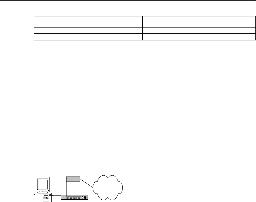
User Manual - Configuration Guide (Volume 3)
Versatile Routing Platform Chapter 2
Configuration of Modem Management
2-5
Table DC-2-7 Configure modem answer mode
Operation Command
MODEM is in automatic answer mode modem-autoanswer
MODEM is I nnon-automatic answer mode no modem-autoanswer
By default, modem is in non-automatic answer mode.
The configuration mainly depends on whether the status of the external modem of the
asynchronous interface is automatic answer mode (i.e., if Modem’s AA indicator is
on).If the modem is in automatic answer mode, the user has to be execute modem-
autoanswer before using dialing function; if modem is not in automatic answer mode,
the user has to be execute no modem-autoanswer.
If the configuration is inconsistent with the modem status, some incoming Modem calls
may not be received normally.
2.4 Typical Configuration of Modem Management
2.4.1 Managing Modem with Modem Script
Quidway router
Modem
PC
PSTN
Figure DC-2-1 Networking diagram of router’s management configuration for modemExample 1:
Modem automatically adapts to baud rate
For the asynchronous interface connected with modem, the baud rate of modem can
be configured with standard AT command, in AT command set, set “AT” to modem, if
“OK” is received, the modem can automatically match the corresponding baud rate,
and the configuration is written into and saved in modem, the corresponding AT
command is “AT&W”, therefore the corresponding configuration procedure is as
follows:
1) Configure modem script
Quidway(config)# chat-script baud "" AT OK AT&W OK
2) Execute the corresponding script under interface configuration mode, assuming
that modem is connected to interface Serial0.
Quidway(config)# interface serial 0
Quidway(config-if-Serial0)# start-chat baud
Example 2: Restore the ex-factory setting of modem
The modem command to restore ex-factory configuration nis “AT&F”, similar to the
configuration procedure of setting baud rate:
Quidway(config)# chat-script factory "" AT OK AT&F OK
Quidway(config)# interface serial 0
Quidway(config-if-Serial0)# start-chat factory

User Manual - Configuration Guide (Volume 3)
Versatile Routing Platform Chapter 2
Configuration of Modem Management
2-6
Example 3: Configure modem initialization parameter
Correctly initialize modem configuration is an important step to connect modem
correctly. The following is a brief introduction to the common AT initialization commands
and work to do for initialization.
z During consulting between modems, modem rates must remain unchanged,
otherwise new rate matching should be performed with AT command.
z Modem locks EIA/TIA-232 serial port rate in different ways. The modem manual
may be consulted to learn how modem locks rate (optional items include &b, \j, &q,
\n or using s register).
z Modem must use data carrier detection (DCD) to indicate the establishment of its
remote connection, such configuration of most modems is performed with &c1
command. Refer to modem manuals for details.
z Modem must allow to hook on its active connection through Data Terminal Ready
(DTR) signal, such configuration for most modems is performed with &d2 or &d3.
Refer to modem manuals for details.
z If the modem is required of call-in function, it must be configured with incoming call
off-hook ringing number, our requirement is not to adopt the automatic answer ring
mode, most modems are configured as S0=0. Refer to modem manuals for
details.
In consideration of the above conditions, our typical initialization string is as follows:
AT&b1&c1&d2&s0=0
Explanation for functionality of the initialization string:
z Lock serial port rate
z Enable DCD detection
z Enable DTR hook-on function
z Configure as non-automatic answer
The procedure to configure is as follows:
Quidway(config)# chat-script init "" AT&b1&c1&d2&s0=0 OK
Quidway(config)# interface serial 0
Quidway(config-if-Serial0)# start-chat init
2.4.2 Remote Configuration Using Modem and Through Asynchronous
Interface
I. Networking requirements
AS introduced above, modem can be used for remote configuration through Console
interface, Quidway router series also support the remote configuration using modem
through asynchronous interface.
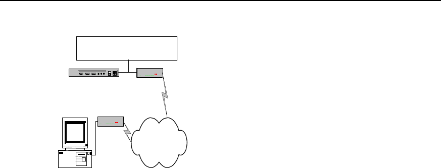
User Manual - Configuration Guide (Volume 3)
Versatile Routing Platform Chapter 2
Configuration of Modem Management
2-7
II. Networking diagram
Modem
PC
PSTN
ModemQuidway Router
Connection available from all
asynchronous interface
Figure DC-2-2 Networking diagram of remote configuration using modem and through asynchronous
interface
III. Configuration procedure
Quidway(config)# interface serial 0
Quidway(config-if-Serial0)# physical asynchronous
Quidway(config-if-Serial0)# modem inout
Quidway(config-if-Serial0)# async mode interactive
2.4.3 Router Initialization with Initialization Script
I. Configuration requirements
Enable the router to initialize the modem connected with asynchronous interface during
power on or restart.
II. Configuration procedure
Quidway(config)# chat-script init "" AT OK AT&B1&C1&D2&S0=1 OK AT&W OK
Quidway(config)# interface serial 0
Quidway(config-if-Serial0)# physical asynchronous
Quidway(config-if-Serial0)# modem
Quidway(config-if-Serial0)# script startup init
2.4.4 Direct Dial with Script
Configuration procedure:
Quidway(config)# chat-script dial "" AT OK ATDT8810058 CONNECT
Quidway(config)# interface serial 0
Quidway(config-if-Serial0)# physical asynchronous
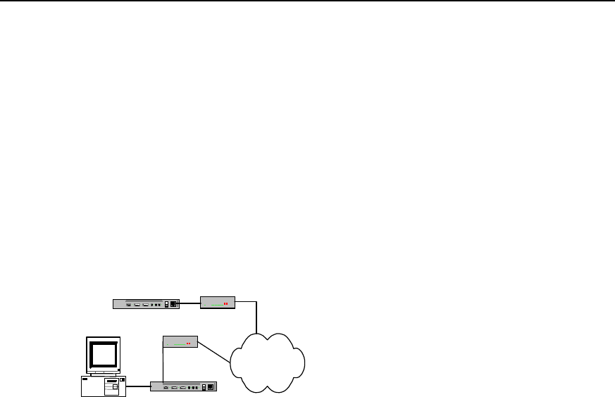
User Manual - Configuration Guide (Volume 3)
Versatile Routing Platform Chapter 2
Configuration of Modem Management
2-8
Quidway(config-if-Serial0)# modem
Quidway(config-if-Serial0)# start-chat dial
2.4.5 Interactively Connect Cisco Router Through Modem
I. Networking requirements
The Quidway router should be interconnected with Cisco router using Modem through
asynchronous interface, and the asynchronous interfaces of both parties should work
in interaction mode, when the physical link is established, Quidway router requires
Cisco router to conduct PPP consulting.
II. Networking diagram
Quidway Router
PC
PSTN
Cisco Modem
Modem
Figure DC-2-3 Networking diagram of interactive connection with cisco router through modem
III. Configuration procedure
Quidway(config)# chat-script cisco Router>-\r-Router> "PPP 1.1.1.1"
Quidway(config)# interface serial 0
Quidway(config-if-Serial0)# physical asynchronous
Quidway(config-if-Serial0)# modem
Quidway(config-if-Serial0)# async mode interactive
Quidway(config-if-Serial0)# script activation cisco
HUAWEI®
VRP
User Manual – Configuration Guide
Volume 3
11 – VoIP Configuration (VC)

User Manual - Configuration Guide (Volume 3)
Versatile Routing Platform Table of Contents
i
Table of Contents
Chapter 1 VoIP Configuration ..................................................................................................... 1-1
1.1 VoIP Overview .................................................................................................................. 1-1
1.1.1 VoIP Principle......................................................................................................... 1-2
1.1.2 IP Voice Implementation over VRP........................................................................ 1-3
1.1.3 IP Voice Feature over VRP .................................................................................... 1-4
1.2 VoIP Configuration............................................................................................................ 1-6
1.2.1 VoIP Configuration Task List.................................................................................. 1-6
1.2.2 Configuring Dial-peer ............................................................................................. 1-6
1.2.3 Configuring Dial Terminator ................................................................................... 1-8
1.2.4 Configuring Abbreviated Dialing............................................................................. 1-9
1.2.5 Configuring Voice Port ........................................................................................... 1-9
1.2.6 Configuring Global Number Match Policy ............................................................ 1-11
1.2.7 Configuring the Recovery Method of Voice Board............................................... 1-11
1.3 VoIP Monitoring and Maintenance.................................................................................. 1-12
1.4 Typical VoIP Configuration Examples ............................................................................ 1-16
1.4.1 Configuring Router FXS Port for Interconnection ................................................ 1-16
1.4.2 Configuring Router FXO and E&M Trunk Ports for Interconnection .................... 1-18
1.4.3 Configuring the Interconnection of Router FXO Port in PLAR Mode................... 1-20
1.4.4 Configuring Interconnection with Refiner for Large Network Solution ................. 1-21
1.5 VoIP Troubleshooting ..................................................................................................... 1-22
Chapter 2 IP Fax Configuration ................................................................................................. 2-1
2.1 Overview to IP Fax............................................................................................................ 2-1
2.2 Configuring IP Fax ............................................................................................................ 2-1
2.2.1 Task List of IP Fax Configuration........................................................................... 2-1
2.2.2 Checking If Configuring Fax to Use ECM Mode .................................................... 2-2
2.2.3 Configuring Fax Rate ............................................................................................. 2-2
2.2.4 Configuring Fax Train Mode................................................................................... 2-3
2.2.5 Configuring Fax Local-train Threshold Value......................................................... 2-3
2.2.6 Configuring Gateway Carrier Transmit Energy Level ............................................ 2-4
2.2.7 Configuring Sending Redundancy Packet Number of T38 Fax Protocol............... 2-4
2.2.8 Configuring the Fax Protocol Intercommunicating with Cisco Equipment ............. 2-5
2.2.9 Configuring the Intercommunication Method with Other Equipment ..................... 2-5
2.3 Monitoring and Maintenance of IP Fax ............................................................................. 2-5
2.4 Typical Configuration of IP Fax......................................................................................... 2-6

User Manual - Configuration Guide (Volume 3)
Versatile Routing Platform Table of Contents
ii
Chapter 3 E1 Voice Configuration .............................................................................................. 3-1
3.1 Overview of E1 Voice Configuration................................................................................. 3-1
3.1.1 Function of E1 Voice ............................................................................................. 3-1
3.1.2 Usage of cE1/PRI Interface................................................................................... 3-1
3.1.3 Features of E1 Voice.............................................................................................. 3-2
3.2 E1 Voice Configuration .....................................................................................................3-3
3.2.1 Configuration Task List of E1 Voice ....................................................................... 3-3
3.2.2 Configuring POTS dial-peer ................................................................................... 3-3
3.2.3 Configuring VoIP dial-peer ..................................................................................... 3-4
3.2.4 Configuring the Basic Parameters of E1 Interface................................................. 3-5
3.2.5 Configuring Voice Port (E1 Interface) .................................................................... 3-6
3.2.6 Configuring E1 Voice R2 Signaling........................................................................ 3-7
3.2.7 Configuring the Basic Parameters of ISDN PRI Interface ................................... 3-10
3.2.8 Configuring Voice Port (ISDN PRI Interface) ....................................................... 3-11
3.3 Monitoring and Maintenance of E1 Voice....................................................................... 3-11
3.4 Typical Configuration Examples of E1 Voice.................................................................. 3-15
3.4.1 Router Connected to PBX through E1 Voice Port ............................................... 3-15
3.4.2 Router Connected to PBX in ISDN PRI Mode ..................................................... 3-17
3.4.3 Two-stage Dialing Configuration .......................................................................... 3-18
3.4.4 Transmission of Data and Voice Simultaneously................................................. 3-20
3.5 Fault Diagnosis and Troubleshooting of E1 Voice.......................................................... 3-21
Chapter 4 GK Client Configuration............................................................................................. 4-1
4.1 Overview of GK Client ......................................................................................................4-1
4.2 Configuration of GK Client ................................................................................................ 4-1
4.2.1 Configuration Task List of GK Client...................................................................... 4-1
4.2.2 Configuring One Interface as H.323 Gateway Interface ........................................ 4-1
4.2.3 Activating or Deactivate GK Client Function .......................................................... 4-2
4.2.4 Configuring Gateway Alias..................................................................................... 4-2
4.2.5 Configure the GK Server Name and Address........................................................ 4-2
4.2.6 Configuring Tech-Prefix ......................................................................................... 4-3
4.2.7 Configuring GK Interworking Mode ........................................................................ 4-3
4.3 Typical Configuration Examples of GK Client................................................................... 4-4
4.4 Fault Diagnosis and Troubleshooting of GK Client........................................................... 4-6
Chapter 5 IPHC Configuration..................................................................................................... 5-1
5.1 Overview of IPHC ............................................................................................................. 5-1
5.2 IPHC Configuration ........................................................................................................... 5-2
5.2.1 Configuration Task List of IPHC............................................................................. 5-2
5.2.2 Enable/disable RTP header compression.............................................................. 5-2
5.2.3. Configure the Max. Connection Number of RTP Header Compressions .............. 5-2

User Manual - Configuration Guide (Volume 3)
Versatile Routing Platform Table of Contents
iii
5.2.4 Configure the Max. Connection Number of TCP Header Compressions .............. 5-3
5.2.5 Configure the Cisco-compatible RTP header compression................................... 5-3
5.2.6 Configure the deleting of udp_chk field from UDP header .................................... 5-3
5.3 Monitoring and Maintenance of IPHC............................................................................... 5-4

User Manual - Configuration Guide (Volume 3)
Versatile Routing Platform Chapter 1
VoIP Configuration
1-1
Chapter 1 VoIP Configuration
1.1 VoIP Overview
VoIP is the abbreviation of Voice over IP. What we often called IP phone is a typical
application of the VoIP. The application of VoIP in router makes it possible that the voice
service can be implemented through the IP network, including the plain phone service
and fax.
VoIP is implemented through voice packet. In VoIP, the digital signal processor (DSP)
splits the voice signals into frames and stores them in packets for transmission. VoIP is
mainly a software solution. It needs the support of voice port board added to the router.
At the beginning of 1995, a kind of software product that could make toll calls on
Internet was available for the first time, and this phone service implemented on Internet
was called Internet phone, this was the early form of the IP phone. Through five years
of development, the IP phone has been developed all over the world as a new type of
phone service, which poses as a great threat to the plain phone service.
The development of IP telephone benefits from the promotion of technology and the
drive of market.
The years of technological accumulation makes the technology of transforming voice
into IP technology increasingly mature and practical. At the same time, the high-speed
development of the integrated circuits (IC) causes the price of the core component of
the IP phone—DSP going down greatly, these factors contribute to the technical
possibility for the promotion of the IP telephone.
The drive of market benefits is also a significant reason for the rapid development of the
IP phone. Using the VoIP network composed of IP voice gateway and other device, we
can bypass the toll calls to the data network, thus greatly reducing large bill for toll
expenses and benefits the subscribers.
Through the development from the beginning of 1990s till now, the IP phone has
developed form the IP software period to the IP gateway period. And also the current
VoIP application has developed from the simple PC products with voice service to the
telecommunication service with multiple services and functionality such as high
reliability, high quality voice, fax and data transmission.
At present, IP gateway is used to interconnect PSTN (Public Switching Telephone
Network) and the Internet, so as to mature the technology of PC to phone, phone to PC
and phone to phone. In addition, voice quality is greatly improved and the commercial
requirements can be satisfied.
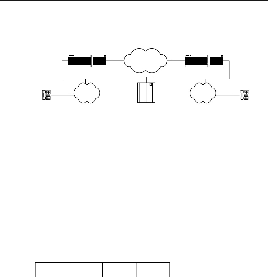
User Manual - Configuration Guide (Volume 3)
Versatile Routing Platform Chapter 1
VoIP Configuration
1-2
1.1.1 VoIP Principle
I. Basic composition
Telephone Telephone
IP network
IP voice gateway IP voice gateway
PSTN PSTN
GateKeeper
Figure VC-1-1 Basic composition of the VoIP system
For the plain voice service, all the functions from the caller to the called are
implemented by PSTN, but IP voice service is quite different.
In the above figure, the IP voice gateway provides the port between the IP network and
the public telephone networks (PSTN/ISDN), and user is connected to the IP voice
gateway through the PSTN local loop. The IP voice gateway is responsible for
converting the analogue signals to digital signals, compressing and packetizing so that
they become packet voice signals that can be transmitted over the IP network. Then,
they are sent to the user gateway and the IP voice gateway at the called end reverts the
packets to recognizable analogue voice signals. Once these signals arrive at the called
terminal through PSTN, a communication process from telephone to telephone
completes. In real VoIP networking, you may need gatekeeper to accomplish functions
such as routing and access control.
VoIP uses UDP (User Datagram Protocol) in the Transport Layer. Since the UDP
provides connectionless and unreliable datagram service, it is not very appropriate for
real-time application. The current approach is to run the RTP (Real-time Transport
Protocol) over the UDP to enhance function of real-time application.
IP header UDP header RTP header Voice load
Figure VC-1-2 VoIP packet format
II. H.323 protocol stack
To realize the VoIP, currently almost all the manufacturers adopt the ITU-T standard
protocol family H.323. The H.323 protocol is implemented in the Application Layer,
which mainly describes the terminals, device and services for multimedia
communication in local area network without quality of service (QoS) guarantee,
including H.225.0, H.245, G.729, G.723.1, G.711, H.261, H.263 and T.120 series, etc.
G.723.1, G.729 and G.711 are audio codec protocols, H.263 and H.261 are video
codec protocols, H.225.0 and H.245 are system control protocols, and the T.120 series
are multimedia data transport protocol.
RTP and its controlled protocols RTCP (RTP Control Protocol) together ensure the
real-timeliness of voice message transmission. The function of RTP is enhanced via
RTCP. RTCP is used to give feedback for the quality of data dispatch. With this

User Manual - Configuration Guide (Volume 3)
Versatile Routing Platform Chapter 1
VoIP Configuration
1-3
feedback, the application system can adapt to different network environment. The
feedback on the quality of transmission is also helpful for the fault location and
diagnosis.
H.323 Protocol stack
Physical Layer
Link Layer
Network Layer
TCP UDP
T.123 RTP, RTCP
T.124, T.125
T.324
T.126 T.127 H.245
H.225.0
RAS
G.711
G.729
G.723.1
G.723.A
H.261
H.263
Data Signaling Audio Video
Figure VC-1-3 H.323 protocol stack
III. A typical telephone call processing by VoIP
Before configuring the voice function for router, please firstly learn the relevant flow of
the Application Program Layer for the smooth configuration.
1) User picks up the hook and the voice interface board detects the action. Then the
board transmits this signal to the VoIP signal processing part over the router.
2) The VoIP Session Application Program plays the dialing tone and waits for the
user to dial.
3) The user begins to dial, and the VoIP session application program collects and
stores the dialed number.
4) After collecting enough number to match a configured destination mode, the
number will be mapped to an IP host through a dial plan mapper. The IP host
directly connects with the target telephone or the PBX. If the PBX is connected,
PBX will accomplish the remaining part of the call.
5) The VoIP session application program uses the H.323 protocol to transmit and
receive voice data channel for the connection in each direction over the IP network.
If the PBX is to processes a call, it will forward the call to the destination telephone.
6) The agreed codec mode is enabled at both ends of connection, which uses the
RTP/UDP/IP as protocol stack to continue the session.
7) Once the end-to-end RTP voice channel is established, the prompt signals of all
the calling procedures and the signals that can be transmitted in the band are
transported through this channel over the IP network. RTCP packet is used to
transmit such information as the transmission quality of voice data in the calling
session.
8) When one calling party is on-hook, the session ends, and both ends resume the
idle state and wait for a new call establishment triggered by the next off-hook.
1.1.2 IP Voice Implementation over VRP
The router serves as voice gateway to provide voice functions, which makes data
conversion from the circuit-switching network to the packet-switching network. During
the conversion, you need to convert the phone numbers to the IP addresses that the

User Manual - Configuration Guide (Volume 3)
Versatile Routing Platform Chapter 1
VoIP Configuration
1-4
packet switching can identify, therefore; the key factor of router configuration lies in the
mapping of the phone numbers and the IP addresses.
The ports that support the voice function in the Quidway series routers include FXS
(Foreign eXchange Station, i.e., the plain telephone service port), FXO (Foreign
eXchange Office, two-wire loop trunk), the E&M trunk port and E1 voice port.
The device with FXS port type must be connected with the device with FXO port type
(the ordinary telephone set is a standard FXO port). The ring current received by the
FXS and FXO is AC current of 25Hz and 60 volts, while the signal received and sent in
the E&M port is DC signal.
Table VC-1-1 The match table between the plain switch and the router interconnection interface
Switch Router Capacity (channel)
Loop trunk line (FXS) FXO 1
Subscriber line (FXO) FXS 1
E&M trunk E&M trunk 1
E1 trunk E1 trunk 30
1.1.3 IP Voice Feature over VRP
The IP voice over the VRP abides by G.711 (A law), G.729, G.723.1, H.225.0, H.245,
and standards such as RFC1889, 1890, etc., which can support the FXS, FXO, E&M
port and E1 port.
The IP voice characteristics over the VRP include:
z Silence suppression
Automatically detect the time segments of silence during session and pause the
generation of data flows during these time segments, so as to reduce the sent voice
data quantity.
z Comfort noise
Through generating appropriate background noise, the sharp voice between the
speaking and pause that resulted from the silence suppression is avoided.
z Jitter buffering
Jitter is caused by the variations of the data packet arrival rate in the network due to the
time delay variation. In order to compensate this jitter, we have added a buffer to the
voice devices at the receiving side to store data packets for enough time length. Thus,
even the slowest packet can arrive in time for processing in sequence. In the mean time,
the buffer can adjust the packet length of the voice port board, and send the voice data
to the voice port board at a stable speed
z Supporting QoS
Since there is high requirement for the real-time voice service, precedence needs to be
given to voice packet sending. You can take the measures such as setting Priority
Queuing (PQ) and Custom Queuing (CQ) at the transmit end. For the configuration of
PQ and CQ, please refer to the relevant sections of the “QoS Configuration “.
z Supporting IP Fax
The IP Fax system is established on the basis of the VoIP, which serves to establish the
fax channel, transmit and receive the fax data. The IP Fax implementation includes
modulation/demodulation, fax protocol processing, IP channel maintenance, etc.

User Manual - Configuration Guide (Volume 3)
Versatile Routing Platform Chapter 1
VoIP Configuration
1-5
The router can also support some special service functions provided by the SPC switch,
such as:
---Do not disturb
After setting the “Do not disturb “ service, no matter if it is idle, the subscriber phone set
will reject any incoming call request, and the caller will only hear the busy tone.
For the DTMF phone set connecting with the voice router, after off-hook, dial *56#, and
the “Do not disturb” service is set. Dial #56#, the setting is removed.
---Call Forwarding on Busy (CFB)
After setting the “Forwarding on busy”, if the subscriber phone set is in seized status,
the new incoming call will be forwarded to the specified phone set.
For the DTMF phone set connecting with the voice router, after off-hook, dial *58*ABCD,
the CFB service is set. Dial #58#, the setting is removed.
Note:
ABCD represents the number of the phone you want to forward the calls to. Please note that this function
only apply to phone set connecting with the router FXS port, and can only specify the phone set that
connects to the same router as this phone set as forwarding destination; otherwise, the setting is invalid.
--- Call Forwarding Unconditional (CFU)
After setting the call forwarding unconditional, no matter the subscriber phone is busy
or not, all the incoming calls will be forwarded to the specified phone set.
For the DTMF phone set connecting with the voice router, after off-hook, dial *57*ABCD
and the CFU service is set. Dial #57#, the setting is removed.
Note:
ABCD represents the number of the phone you want to forward calls to. Please note that this function only
apply to phone set connecting with the router FXS port, and can only specify the phone set that connects
to the same router as this phone set as forwarding destination, otherwise it is invalid.
---Alarm clock service
After setting the alarm clock service, when the time set by the subscriber is up, the
phone set will continue to ring for 45 seconds and then hang up. This function only
validate during the 24 hours after setting.
For the DTMF phone set connecting with the voice router, after off-hook, dial
*55*HHMM for the service setting and dial #55# to remove the setting.
Note:
HH stands for hour, the virtual value is integer within the range from 0 to 23, and MM stands for minute, the
virtual value is integer within the range from 0 to 59.
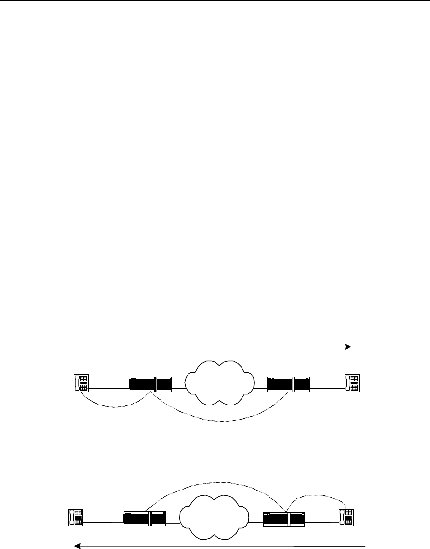
User Manual - Configuration Guide (Volume 3)
Versatile Routing Platform Chapter 1
VoIP Configuration
1-6
---Line group access
Set line group access, you can set multiple physical lines as one phone number, in this
case if there is an incoming call, it will automatically select the idle line for the reply to
reduce the configuration complexity and increase the networking capacity.
1.2 VoIP Configuration
1.2.1 VoIP Configuration Task List
The configuration tasks of the VoIP include:
z Configuring dial-peer
z Configuring dial terminator
z Configuring abbreviated dialing
z Configuring voice port
z Configuring the global number match policy
z Configuring the recovery method of voice board
1.2.2 Configuring Dial-peer
The key to mastering the VoIP configuration lies in understanding the dial-peers.
According to different locations (the calling side or the called side), we can divide a call
into four segments in a complete phone-to-phone connection and each segment
(called call leg) corresponds to a dial-peer.
IP Network
Call leg for
IP Network
Router Router
IP Network
Source Destination
Call leg for POTS
dial peer 1 Call leg for VOIP
dial peer 2
Source
Destination
Call leg for POTS
dial peer 4
Call leg for VOIP
dial peer 3
Router
IP Network
Router
Figure VC-1-4 Call division viewed from the router at both ends
From the above figure, we can see that, there are two types of the dial-peers used in
voice communications:
z POTS dial-peer
z VoIP dial-peer

User Manual - Configuration Guide (Volume 3)
Versatile Routing Platform Chapter 1
VoIP Configuration
1-7
I. POTS dial-peer configuration
POTS is the abbreviation of the Plain Old Telephone Service, which refers to ordinary
telephone service. The POTS dial-peer configuration means to establish relationship
between the physical voice port and the local telephone device. Generally we only
need to configure two commands: destination-pattern and port. The command of
destination-pattern is used to define phone numbers related to POTS dial-peer, and
the command of port connect the POTS dial-peer with an actual voice port which is
usually the voice port connecting the router to the local office. Furthermore, prefix
should be configured for the outgoing PBX subscribers.
Please use the command dial-peer voice pots in the global configuration mode, and
use other configurations in the dial-peer configuration mode.
Table VC-1-2 POTS dial-peer configuration commands
Operations Commands
Configure POTS dial-peer and enter the POTS configuration dial-peer voice number pots
Delete the POTS dial-peer no dial-peer voice number
Disable truncating the called number cancel-truncate
Truncate the called number no cancel-truncate
Configure dial-peer destination pattern (phone number) destination-pattern string
Delete the dial-peer destination pattern (phone number) no destination-pattern
Set IP packet precedence ip precedence priority-number
Restore the IP packet precedence to the default no ip precedence
Configure the local port number port port-number
Cancel the local port number no port
Configure the phone number prefix prefix string
Cancel the phone number prefix no prefix
Disable the POTS dial-peer shutdown
Enable the POTS dial-peer no shutdown
Enable the silence detection vad
Disable the silence detection no vad
By default, the command no cancel-truncate (i.e., truncate the called number) and the
command no vad (disable the silence detection) are valid.
The default value of the configuration command ip precedence (IP packet precedence)
is 0.
II. VoIP dial-peer configuration
The VoIP dial-peer configuration involves the corresponding of the phone numbers with
the IP addresses. The key configuration commands are destination-pattern and
session target. The destination-pattern defines the phone numbers related to the VoIP
dial-peer, and the session target specifies the destination IP address for the VoIP
dial-peer.

User Manual - Configuration Guide (Volume 3)
Versatile Routing Platform Chapter 1
VoIP Configuration
1-8
Note:
The configuration commands here are addressed to the router, and the “Incoming” and “Outgoing” are
also defined in respect of router. Therefore, the POTS dial-peer uses the destination-pattern to define the
phone number of the phone set connected with the local router voice port, while the VoIP dial-peer uses
the destination-pattern to define the called number.
Please use the command dial-peer voice voip in the global configuration mode, and
use other configurations in the dial-peer configuration mode.
Table VC-1-3 VoIP dial-peer configuration commands
Operations Commands
Configure the VoIP dial-peer and enter the VoIP
configuration dial-peer voice number voip
Delete the VoIP dial-peer no dial-peer voice number
Configure the codec mode codec { 1st-priority-level | 2nd-priority-level | 3rd-
priority-level | 4th-priority-level } { g711alaw |
g711ulaw | g723r53 | g723r63 | g729r8 }
Restore the codec default value no codec { 1st-priority-level | 2nd-priority-level |
3rd-priority-level | 4th-priority-level }
Configure phone number destination-pattern string
Delete phone number no destination-pattern
Set IP packet precedence ip precedence priority-number
Restore the IP packet precedence to the default value no ip precedence
Configure the target IP address session target { ipv4:a.b.c.d | ras }
Delete the configured IP address no session target
Disable the VoIP dial-peer shutdown
Enable the VoIP dial-peer no shutdown
Configure the technical prefix of the H.323 gateway tech-prefix string
Delete the technical prefix of the H.323 gateway no tech-prefix
Enable the silence detection vad
Disable the silence detection no vad
By default, the command no tech-prefix (i.e., do not configure the technical prefix of
the H.323 gateway at the beginning) validates, and the command no vad (Disable the
silence detection) validates.
The default of the configuration command codec (voice codec mode) is g729r8. The
default of the configuration command ip precedence (IP packet precedence) is 0.
1.2.3 Configuring Dial Terminator
The dial terminator configuration can notify the router that, on receiving the keystroke
input, the dialing is finished and it will begin to make mode match and find the called
end.
Please make the following configurations in the global configuration mode:

User Manual - Configuration Guide (Volume 3)
Versatile Routing Platform Chapter 1
VoIP Configuration
1-9
Table VC-1-4 Configuring the dial terminator
Operations Commands
Configure the dial terminator dial-peer terminator character
Delete the dial terminator no dial-peer terminator
By default, we do not configure the dial terminator.
1.2.4 Configuring Abbreviated Dialing
In many enterprises, the first several digits of all the phone numbers are the same, and
you only need to dial the last several digits for internal call. The VoIP service can also
use this kind of abbreviated dialing with the command num-exp. After the dialing
completes, the abbreviated dialing will automatically expand to the complete E.164
number.
Please make the following configurations in the global configuration mode.
Table VC-1-5 Configuring abbreviated dialing
Operations Commands
Configure the abbreviated dialing num-exp extension-number expanded-number
Delete the abbreviated dialing no num-exp extension-number
By default, we do not configure the abbreviated dialing.
1.2.5 Configuring Voice Port
The router provides analogue voice ports for the implementation of the VoIP. The
signaling type of these analogue voice ports depends upon the VI (Voice Interface)
board installed. The command voice-port is used to configure the characteristics
related to the special voice port signaling type.
The voice port support the following three basic voice signaling types:
z FXS (Foreign eXchange Station): FXS port used the standard RJ-11 line to
directly connect with the device such as ordinary phone set, fax, PBX, etc., which
can provide ring, voltage and dial tone.
z FXO (Foreign eXchange Office): two wire loop trunk, the FXO port uses RJ-11 line
to connect the local calls to the PSTN central office or to the PBX that does not
support the E&M signalings. The FXO port device can only connect to device with
FXS port.
z E&M: The E&M port uses the RJ-45 line to connect the remote calls from the IP
network to the PBX trunk. The E&M signaling provides the on-hook and off-hook
signals and reduces the interference to some lower degree, which is usually used
in the PBX backbone or connection line.
The voice port configuration mainly involves the configuration of some physical
characteristics. Usually, you can use defaults for the physical port parameters and do
not need to configure again.
Please use the command voice-port in the global configuration mode, and make other
configurations in the voice-port configuration mode.

User Manual - Configuration Guide (Volume 3)
Versatile Routing Platform Chapter 1
VoIP Configuration
1-10
Table VC-1-6 Configuring voice-port
Operations Commands
Configure voice physical port voice-port port-number
Set the busy tone detection type for the port area { north-america | custom | europe }
Restore the port detection busy tone type to the default no area
Enable comfort noise setting comfort-noise
Disable comfort noise setting no comfort-noise
Specify E.164 phone number of the destination end connection plar string
Delete E.164 phone number of the destination end no connection plar
Configure the port description character string description string
Delete the port description character string no description
Enable the echo cancellation function or set the sample
length of the echo cancellation echo-cancel { enable | coverage coverage-time }
Cancel the echo cancellation function or restore the
sample length of the echo cancellation to the default no echo-cancel { enable | coverage }
Configure the voice input gain input gain value
Restore the voice input gain to the default no input gain
Configure the E&M trunk circuit type operation { 2-wire | 4-wire }
Delete the available wire selection scenario no operation { 2-wire | 4-wire }
Configure the voice output attenuation output attenuation value
Restore the voice output attenuation to the default no output attenuation
Set the port start mode signal { loopstart | groudstart | wink-start | immediate
| delay-dial }
Delete the set voice port start mode no signal { loopstart | groudstart | wink-start |
immediate | delay-dial }
Configure the relevant time interval of the voice port
dialing timeouts {call-disconnect | initial | interdigit }
seconds
Restore the relevant time interval of the voice port dialing
to the default no timeouts {call-disconnect | initial | interdigit }
Configure the relevant time parameters in the E&M port timing {delay-duration | delay-start | digit | interdigit |
wink-duration | wink-wait } milliseconds
Restore the relevant time parameters in the E&M port to
the default no timing {delay-duration | delay-start | digit |
interdigit | wink-duration | wink-wait }
Configure the E&M trunk type type { 1 | 2 | 3 | 5 }
The E&M trunk type specified in the configuration no type { 1 | 2 | 3 | 5 }
The default of the configuration command operation (E&M trunk circuit type) is 4-wire.
The default of the configuration command signal (port start mode) for the FXS and
FXO ports is loop start, and for the E&M port, its default is immediate.
The value for configuration command input gain is 0 and the value for output
attenuation is 0. The default value of the configuration command timeouts initial
(initialization timeout interval) is 10s.
The default value of the configuration command timeouts interdigit (keystroke
timeout interval) is 10s.
The default value of the configuration command timing delay-duration (timing delay
timeout interval) is 400 ms.
The default value of the configuration command timing delay-start (timing delay start
timeout interval) is 300 ms.
The default value of the configuration command timing digit (DTMF signal duration) is
120 ms.

User Manual - Configuration Guide (Volume 3)
Versatile Routing Platform Chapter 1
VoIP Configuration
1-11
The default value of the configuration command timing interdigit (time interval
between the DTMF signals) is 120 ms.
The default value of the configuration command timing wink-duration (wink time
delay interval) is 500 ms.
The default value of the configuration command timing wink-wait (wink-wait time
interval) 500 ms.
The default value of the configuration command type (E&M trunk type) is 5.
1.2.6 Configuring Global Number Match Policy
To better adapt to the diversity of the subscriber dial plan, the number match policy
includes match as per the longest number or the shortest number. When using the
longest number match, if the input number length is less than the number length
configured by the command destination-pattern, please wait until timeout, and then
select the shortest number policy. When using the shortest number match, if the input
number length is greater than that configured by the command destination-pattern,
then the redundant numbers will be neglected.
Please make the following configurations in the global mode:
Table VC-1-7 Configuring the global number match policy
Operations Commands
Configure the number match policy of the whole office voip match-policy { longest | shortest }
By default, please use the shortest number match policy.
1.2.7 Configuring the Recovery Method of Voice Board
When the voice board becomes abnormal for some reason, two methods can be
adopted to recover the board, i.e., the manual recovery and automatic recovery. After
enabling the WATCHDOG, it will monitor the board status every five seconds and will
automatically recover the board if any abnormality is detected. In this case, manual
interference is not necessary. If WATCHDOG is disabled, the board cannot be
recovered automatically if any abnormality occurs and manual recovery is needed.
Please make the following configuration in global configuraiton mode.

User Manual - Configuration Guide (Volume 3)
Versatile Routing Platform Chapter 1
VoIP Configuration
1-12
Table VC-1-8 Configuring the recovery method of voice board
Operations Commands
Enable WATCHDOG voip enable-watchdog
Disable WATCHDOG voip disable-watchdog
By default, WATCHDOG is enabled.
1.3 VoIP Monitoring and Maintenance
Please use the command voip reset in the global configuration mode, and use the
following commands show and debug in the privileged user mode.
Table VC-1-9 VoIP monitoring and maintenance
Operations Commands
Reset the voice board voip reset slot-number
Display the call information of the voice port show call-history voice-port number
Display the call statistic information of the KHT module show kht statistics
Display the call control block information in the RCV module show rcv ccb
Display the call statistic information between the RCV
module and other modules show rcv statistic { all | call | cc | error | ipp | proc
| timer | vpm | vpp }
Display the voice port information show voice-port number
Display various statistic information in the VPP module show vpp [ channel channel-no ]
Enable the debugging information output switch of the
H.225.0 negotiated packets or events debug h225 { asn1 | event }
Enable the debugging information output of the H.245
negotiated packets or event debug h245 { asn1 | event }
Enable the debugging information output of the KHT module debug kht { all | error | ipp | rcv | timer | vpp }
Enable the debugging information output of the RCV module debug rcv { all | cc | error | ipp | timer | vpm | vpp }
Enable the debugging information output of the VPM module debug vpm { all | buffer | command | dsp | em |
error | ipp | port | receive | send }
Enable the debugging information output of the VPP module debug vpp { all | codecm | error | ipp | kht | rcv |
timer | vpm }
1) Display the call information of the voice port
Quidway# show call-history voice-port 2
Voice-port 2 type FXS POTS, Line state is opened
start outgoing call 4 times, 3 success
receive incoming call 8 times, 6 success
the latest 10 calling number is:
%1% called number 1001
%2% called number 1001
%3% called number 1001
%4% called number 1001
The above information indicates that the type of the voice port 2 is FXS, the line is in an
activated status. Four calls are originated at this port, in which three are successful
calls. There are eight calls received, in which six are successful. The ten latest called
numbers originated at this port, if the calls are less than ten, it will display as per the
actual calls.
2) Display the call statistic information of the KHT module
Quidway# show kht statistics
KHT: Receive IPP packet, begin KHT flow: 0

User Manual - Configuration Guide (Volume 3)
Versatile Routing Platform Chapter 1
VoIP Configuration
1-13
KHT: Dial successfully, match POTS dial-peer: 0
KHT: Dial successfully, match VoIP dial-peer: 0
KHT: Dial successfully, NOT match dial-peer: 0
KHT: Send IPAlerting packet to RCV: 0
KHT: Send IPConnect packet to RCV: 0
KHT: Send PlayDialTone packet to VPP: 0
KHT: Send RecvNum packet to VPP: 0
KHT: Timer malloc failed: 0
KHT: Invalid timer error: 0
KHT: Invalid timeout packet error: 0
KHT: Receive invalid packet from IPP: 0
KHT: Receive invalid packet from VPP: 0
KHT: Receive invalid phone number from IPP: 0
KHT: CCB NOT found: 0
KHT: CCB status error: 0
The above information indicates the amount of various types of information in
sequence. The information includes the amount of the following packets:
z packet of receiving the IPP module
z successful dialing and matching the POTS dial-peer
z successful dialing and matching the VoIP dial-peer
z successful dialing but not matching the dial-peer
z the ring packet sent by the KHT to the RCV module
z the connection establishment packet sent by the KHT to the RCV module
z the prompt tones playing packet sent by the KHT to the VPP module
z the dialing number receiving packet sent by the KHT to the VPP module
z timer distribution error
z invalid timer error
z invalid timeout packet
z invalid information received by the IPP module
z invalid information received by the VPP module
z the invalid phone numbers received by the IPP module
z the call control block (CCB) not found
z CCB status error, etc.
3) Display the call control block information in the RCV module
Quidway# show rcv ccb
RCV : CCB [ 1 ]
{
CallID : 0x0043
CallState : TALK
IppID : 0x004f
IppState : IPPS_CONNECTED
CcID : 0xffff
CcState : CCS_CONNECTED
VpmID : 0xffff
CallType : OUTGOING
CallAttribute : 0x00000000
CallSignaling : 0x00000002
EncodeType : 0x0000001f
E1Slot : 0xffffffff
E1Port : 0xffffffff
TimeSlot : 0xffffffff
ChannelID : 0x00000003
VpuState : VS_CONNECTED
IppTimer : 0x00000000
CcTimer : 0x00000000
VpuTimer : 0x00000000
CcChanMsg : 0x00000000
E1ChanMsg : 0x00000000
CallerNumber : 111
CalledNumber : 660010
prev : 0x00000000
next : 0x01409500

User Manual - Configuration Guide (Volume 3)
Versatile Routing Platform Chapter 1
VoIP Configuration
1-14
}
The above information indicates that the call control block 1 serves as outgoing call, the
state of each module is connection established, the call state is in call process, the
calling number is 111 and the called number is 660010.
RCV : CCB [ 2 ]
{
CallID : 0x0042
CallState : TALK
IppID : 0x004e
IppState : IPPS_CONNECTED
CcID : 0xffff
CcState : CCS_CONNECTED
VpmID : 0x0039
CallType : INCOMING
CallAttribute : 0x00000000
CallSignaling : 0x00000004
EncodeType : 0x00000009
E1Slot : 0xffffffff
E1Port : 0xffffffff
TimeSlot : 0xffffffff
ChannelID : 0x00000000
VpuState : VS_CONNECTED
IppTimer : 0x00000000
CcTimer : 0x00000000
VpuTimer : 0x00000000
CcChanMsg : 0x00000000
E1ChanMsg : 0x00000000
CallerNumber : 111
CalledNumber : 660010
prev : 0x01409000
next : 0x00000000
}
The above information indicates that the call control block 2 serves as incoming call,
the state of each module is connection established, the call state is in call process, the
calling number is 111 and the called number is 660010.
4) Display the call statistic information between the RCV module and other modules
Quidway# show rcv statistic call
Statistic about RCV calls :
{
RCV_CC_ACTIVE_CALL : 0
RCV_CC_ACTIVE_CALL_SUCCEEDED : 0
RCV_CC_ACTIVE_CALL_FAILED : 0
RCV_CC_PASSIVE_CALL : 0
RCV_CC_PASSIVE_CALL_SUCCEEDED : 0
RCV_CC_PASSIVE_CALL_FAILED : 0
RCV_R2_ACTIVE_CALL : 5
RCV_R2_ACTIVE_CALL_SUCCEEDED : 2
RCV_R2_ACTIVE_CALL_FAILED : 3
RCV_R2_PASSIVE_CALL : 4
RCV_R2_PASSIVE_CALL_SUCCEEDED : 1
RCV_R2_PASSIVE_CALL_FAILED : 3
RCV_VPM_ACTIVE_CALL : 39
RCV_VPM_ACTIVE_CALL_SUCCEEDED : 11
RCV_VPM_ACTIVE_CALL_FAILED : 28
RCV_VPM_PASSIVE_CALL : 18
RCV_VPM_PASSIVE_CALL_SUCCEEDED : 15
RCV_VPM_PASSIVE_CALL_FAILED : 3
}
The above information indicates the total number of the CC, R2 signaling in the RCV
module and the call packets of each VPM module, the number of successful call
packets, the number of the failed call packets. Using the other parameters (such as CC,
IPP, VPM, etc), it will display the statistic information in corresponding module.

User Manual - Configuration Guide (Volume 3)
Versatile Routing Platform Chapter 1
VoIP Configuration
1-15
5) Display the voice port information
! Execute this command for a voice port in calling progress.
Quidway# show voice-port 0
Voice-port 0 type FXS POTS , Line state is opened
channel status is CH_TALKING
coding protocol 729, decoding protocol 729
calling number 1001 called number 2001, direction outgoing
Call-ID is 2 Call-reference is 12
comfort-voice is enabled, reset 0 times
Administrative State is UP
In Gain is Set to 0 dB
Out Attenuation is Set to 0 dB
Echo Cancellation is enable
Initial Time Out is set to 10 s
Interdigit Time Out is set to 10 s
The above information indicates that the voice port type is FXS, the line is in activated
state, the voice port is calling progress now, the codec mode is G.729, the calling
number is 1001 and the called number is 2001.
! Execute this command for a currently idle voice port.
Quidway# show voice-port 0
Voice-port 0 type FXS POTS , Line state is opened
channel status is CH_IDLE
coding protocol 0, decoding protocol 0
calling number called number , direction outgoing
Call-ID is 2 Call-reference is 0
comfort-voice is enabled, reset 0 times
Administrative State is UP
In Gain is Set to 0 dB
Out Attenuation is Set to 0 dB
Echo Cancellation is enable
Initial Time Out is set to 10 s
Interdigit Time Out is set to 10 s
Since the voice codec mode is mutually negotiated and determined in the session, we
cannot see the codec information in the idle state.
6) Display various statistic information in the VPP module
Quidway# show vpp
Channel = 0 Status = CH_TRANSFRAME
ConnectRightTimes = 53 ConnectWrongTimes = 0
DisConnectRightTimes = 52 DisConnectWrongTimes = 0
RecvCodecmDataRightTimes = 577898 RecvCodecmDataWrongTimes = 0
SendCodecmDataRightTimes = 78272 SendCodecmDataWrongTimes = 0
RecvIppDataRightTimes = 78275 RecvIppDataWrongTimes = 0
SendIppDataRightTimes = 577906 SendIppDataWrongTimes = 0
RecvCodecmDataBytes = 17337270 RecvIppDataBytes = 1845370
Channel = 1 Status = CH_IDLE
ConnectRightTimes = 4 ConnectWrongTimes = 0
DisConnectRightTimes = 4 DisConnectWrongTimes = 0
RecvCodecmDataRightTimes = 207 RecvCodecmDataWrongTimes = 0
SendCodecmDataRightTimes = 181 SendCodecmDataWrongTimes = 0
RecvIppDataRightTimes = 181 RecvIppDataWrongTimes = 0
SendIppDataRightTimes = 207 SendIppDataWrongTimes = 0
RecvCodecmDataBytes = 6210 RecvIppDataBytes = 5430
……
Total
ConnectRightTimes = 66 ConnectWrongTimes = 0
DisConnectRightTimes = 64 DisConnectWrongTimes = 0
RecvCodecmDataRightTimes = 607188 RecvCodecmDataWrongTimes = 2
SendCodecmDataRightTimes = 107473 SendCodecmDataWrongTimes = 0
RecvIppDataRightTimes = 107473 RecvIppDataWrongTimes = 0
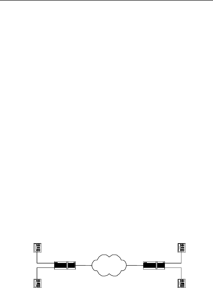
User Manual - Configuration Guide (Volume 3)
Versatile Routing Platform Chapter 1
VoIP Configuration
1-16
SendIppDataRightTimes = 607188 SendIppDataWrongTimes = 0
RecvCodecmDataBytes = 18215640 RecvIppDataBytes = 2721160
The above information indicates the information as follows:
z times of right and wrong connection establishment in each voice channel
z the times of correct and wrong disconnection
z the times of correct and wrong coding data receiving
z the times of correct and wrong coding data sending
z the times of correct and wrong IPP data receiving
z the times of correct and wrong IPP data sending
z the total number of the received coding data byte
z the total number of the received IPP data byte.
1.4 Typical VoIP Configuration Examples
1.4.1 Configuring Router FXS Port for Interconnection
I. Networking requirements
Telephones in Beijing and Shenzhen can directly make phone calls via WAN through
router with voice functions.
This network connected in this way is of simple structure, subscribers can directly make
phone calls from the router. But the shortcoming of this kind of network is the small
capacity, so the group calls cannot be implemented. This scenario is applicable for
small office system.
The FXS (POTS) port number of the router determines the number of the phones that
the router can support to directly access. Depending upon the type, the router can at
maximum connect with three or seven voice interface boards respectively. According to
the port type, the voice interface board can be divided into FXO board, FXS board and
E&M board, which provide two or four FXO ports, FXS ports and E&M ports
respectively.
II. Networking diagram
WAN
-
WAN
Router_Beijing Router_Shenzhen
WAN
1.1.1.1
WAN
2.2.2.2
port 0
port 1
port 0
port 1
-
010-1002
Tel.2
Tel.3
0755-2001
0755-2002
Tel.4
Tel.1
010 1001
Figure VC-1-5 The router directly connects with ordinary DTMF phones

User Manual - Configuration Guide (Volume 3)
Versatile Routing Platform Chapter 1
VoIP Configuration
1-17
III. Configuration procedures
1) Router_Beijing configuration:
Quidway# config
! Configure VoIP dial-peer.
Quidway(config)# dial-peer voice 4 voip
! Configure the called number, the dot is wildcard character.
Quidway(config-peer-voip4)# destination-pattern 0755....
! Configure the IP address of the called party.
Quidway(config-peer-voip4)# session target ipv4:2.2.2.2
! Configure the local ports Tel.1 connects with.
Quidway(config-peer-voip4)# dial-peer voice 6 pots
! Configure the phone number of Tel.1.
Quidway(config-peer-pots6)# destination-pattern 0101001
! Configure the relationship between POTS dial-peer 6 and port 0.
Quidway(config-peer-pots6)# port 0
! Configure the local ports Tel.2 connects with.
Quidway(config-peer-pots6)# dial-peer voice 5 pots
! Configure the phone number of Tel.2.
Quidway(config-peer-pots5)# destination-pattern 0101002
! Configure the relationship between POTS dial-peer 5 and port 1.
Quidway(config-peer-pots5)# port 1
2) Router_Shenzhen configuration
Quidway# config
Quidway(config)# dial-peer voice 1 voip
Quidway(config-peer-voip1)# destination-pattern 010....
Quidway(config-peer-voip1)# session target ipv4:1.1.1.1
! Configure the local ports Tel.3 connects with.
Quidway(config-peer-voip1)# dial-peer voice 4 pots
Quidway(config-peer-pots4)# destination-pattern 07552001
Quidway(config-peer-pots4)# port 0
! Configure the local ports Tel.4 connects with.
Quidway(config-peer-pots4)# dial-peer voice 5 pots
Quidway(config-peer-pots5)# destination-pattern 07552002
Quidway(config-peer-pots5)# port 1
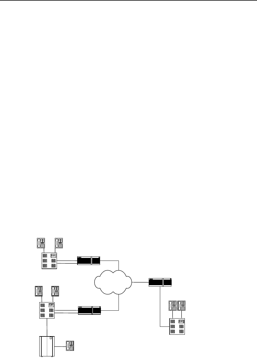
User Manual - Configuration Guide (Volume 3)
Versatile Routing Platform Chapter 1
VoIP Configuration
1-18
1.4.2 Configuring Router FXO and E&M Trunk Ports for Interconnection
I. Networking requirements
There is a local telephone network established by PBX in Beijing, Shenzhen and
Shanghai respectively, it is required that the three networks implement interconnection
via three routers with voice function and the internal PBX subscribers can make non-
local ordinary calls via VoIP.
The routers in Beijing and shanghai can provide the FXO ports, while the router in
Shenzhen uses the E&M port.
You may select any of the following modes for the connection of any router and the
PBX:
z The routers provide the FXS ports, the PBXs provide two wire loop trunk port
FXOs
z The routers provide the FXO ports, the PBXs provide ordinary line port FXSs
z All the routers and the PBXs provide the E&M trunk ports
The number of connection established between the PBX subscribers in Shenzhen and
Beijing are determined by the smaller one of the number of Router_Shenzhen E&M
trunk ports and Router_Beijing FXO trunk ports, so it is with Shanghai.
In the following figure, Tel.1 in Beijing is an ordinary PSTN subscriber. If not using VoIP,
when the subscribers in Shenzhen or Shanghai dial Tel.1, they need to add the area
code 010, but through the VoIP configuration, instead of dialling the area code, you can
call in local mode, which is very convenient and can also save call charge.
Provided that when the internal PBX subscribers in the three cities make external calls,
they need to dial “0” firstly.
II. Networking diagram
WAN
Router_ Shanghai
021-1001 021-1002
FXO
E&M
Port6
WAN
3.3.3.3
WAN
2.2.2.2
Router_Beijing
FXO WAN
1.1.1.1
010-1001
010-1002
PBX
PBX
0755-2002
PBX
Tel.1
010-6543
PSTN
Port0
Port1
Port1
Port0
Beijing
Shanghai
Shenzhen
Router_Shenzhen
0755-2001
Figure VC-1-6 The routers connect with the PBXs via the E&M trunk

User Manual - Configuration Guide (Volume 3)
Versatile Routing Platform Chapter 1
VoIP Configuration
1-19
III. Configuration procedures
1) Router_Beijing configuration:
! Configure the VoIP dial-peer to Shenzhen.
Quidway(config)# dial-peer voice 0755 voip
Quidway(config-peer-voip775)# destination-pattern 0755....
Quidway(config-peer-voip775)# session target ipv4:2.2.2.2
! Configure the VoIP dial-peer to Shanghai.
Quidway(config-peer-voip775)# dial-peer voice 021 voip
Quidway(config-peer-voip21)# destination-pattern 021....
Quidway(config-peer-voip21)# session target ipv4:3.3.3.3
! Configure local port Port0.
Qduiway(config-peer-voip21)# dial-peer voice 4 pots
Quidway(config-peer-pots4)# destination-pattern 010....
Quidway(config-peer-pots4)# port 0
! Configure prefix, dial 0 first for outgoing call, and the comma indicates that it will send
the number 500 ms after sending the prefix “0”.
Quidway(config-peer-pots4)# prefix 0,
! Configure the local port Port 1.
Quidway(config-peer-pots4)# dial-peer voice 5 pots
Quidway(config-peer-pots5)# destination-pattern 010....
Quidway(config-peer-pots5)# port 1
! Configure prefix, dial “0” first for outgoing calls, with 500 ms time delay.
Quidway(config-peer-pots5)# prefix 0,
2) The configuration of Router_Shanghai is the same as that of Router_Beijing.
3) Router_Shenzhen configuration:
Quidway# config
! Configure the VoIP dial-peer to Shanghai.
Quidway(config)# dial-peer voice 21 voip
Quidway(config-peer-voip21)# destination-pattern 021....
Quidway(config-peer-voip21)# session target ipv4:3.3.3.3
! Configure the VoIP dial-peer to Beijing.
Quidway(config-peer-voip21)# dial-peer voice 010 voip
Quidway(config-peer-voip10)# destination-pattern 010....
Quidway(config-peer-voip10)# session target ipv4:1.1.1.1
! Configure the local port Port 6.
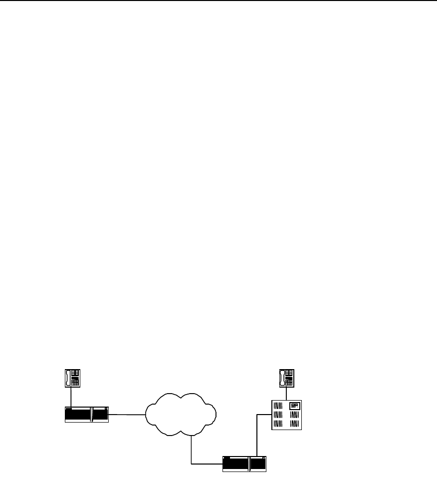
User Manual - Configuration Guide (Volume 3)
Versatile Routing Platform Chapter 1
VoIP Configuration
1-20
Qduiway(config-peer-voip10)# dial-peer voice 7 pots
Quidway(config-peer-pots7)# destination-pattern 0755....
Quidway(config-peer-pots7)# port 6
! E&M port setting.
Quidway(config-peer-pots7)# voice-port 6
Quidway(config-voice-port6)# signal wink-start
Quidway(config-voice-port6)# operation 4-wire
Quidway(config-voice-port6)# type 5
1.4.3 Configuring the Interconnection of Router FXO Port in PLAR Mode
I. Networking requirements
We specify that the FXO port of Router_Shenzhen works in the PLAR (Private Line
Auto Ringdown) mode, the default remote connection phone number is 0101001.
When the PBX subscriber 0755-2001 dials the number 0755-2003, firstly it will connect
with the Router_Shenzhen. Since the FXO port works in the PLAR mode, it will
automatically use the set remote connection number to request connection with the
subscriber 010-1001 in Beijing.
II. Networking diagram
WAN
WAN
PBX
Router_Beijing
Router_Shenzhen
010-1001
WAN
1.1.1.1
WAN
2.2.2.2
0755-2001
0755-2003
Port 0
FXO Port1
Figure VC-1-7 Router_Shenzhen FXO works in the PLAR mode
III. Configuration procedures
1) Router_Beijing configuration
Quidway(config)# dial-peer voice 4 voip
Quidway(config-peer-voip4)# destination-pattern 0755....
Quidway(config-peer-voip4)# session target ipv4:2.2.2.2
Quidway(config-peer-voip4)# dial-peer voice 5 pots
Quidway(config-peer-pots5)# destination-pattern 0101001
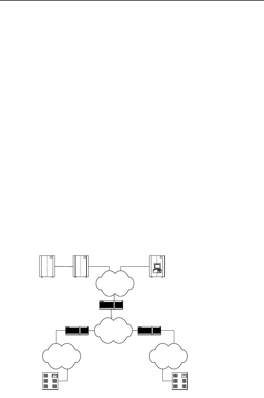
User Manual - Configuration Guide (Volume 3)
Versatile Routing Platform Chapter 1
VoIP Configuration
1-21
Quidway(config-peer-pots5)# port 0
2) Router_Shenzhen configuration
Quidway# config
Quidway(config)# dial-peer voice 10 voip
Quidway(config-peer-voip10)# destination-pattern 010....
Quidway(config-peer-voip10# session target ipv4:1.1.1.1
Quidway(config-peer-voip10)# dial-peer voice 11 pots
Quidway(config-peer-pots11)# destination-pattern 07552001
Quidway(config-peer-pots11)# port 1
! Make the following FXO Port1 configuration.
Quidway(config)# voice-port 1
Quidway(config-voice-port1)# connection plar 0101001
1.4.4 Configuring Interconnection with Refiner for Large Network Solution
I. Network requirements
Router_Beijing and Router_Shanghai connect with the PBXs via trunk port, while
Router_Shenzhen connects with Quidway A8010 Refiner through the Ethernet via a
high-speed router. With the separated data and voice service, the network processing
capacity can be improved. The burden of VoIP and the voice service of large Intranet
can be lessened. With the expansion of the enterprise scale, you may use GateKeeper
to carry out management according to actual requirements.
II. Networking diagram
PBX PBX
PSTNPSTN
Router_1
Router_3
Router_2
Public Switch A8010 Refiner
E1
WAN
LAN
Shenzhen
Beijing Shanghai
Gate keeper Gate keeper

User Manual - Configuration Guide (Volume 3)
Versatile Routing Platform Chapter 1
VoIP Configuration
1-22
Figure VC-1-8 Interconnecting mode of the voice router and the voice gateway
III. Configuration description
In the networking diagram, Router_1 and Router_2 are routers with voice function. In
configuration, the session target should point to the interface between the A8010
Refiner and the Ethernet.
Since the A8010 Refiner itself does not have routing function, we need Router_3 to
implement the work related to routing function.
1.5 VoIP Troubleshooting
Fault 1: The user hears busy tone after dialing.
Troubleshoot: Take the following procedures.
z Firstly check that the remote router exists and you can ping the remote IP address.
z Check that the dial-peer configuration is correct.
z Check that the phone number configuration is correct. You can use the command
show call voice-port number to view the call history.
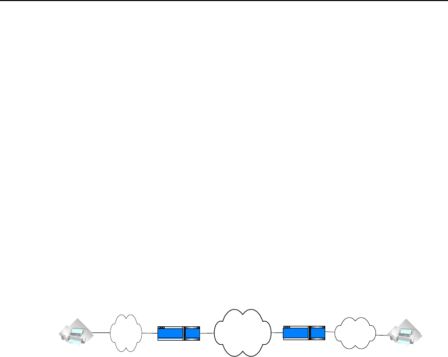
User Manual - Configuration Guide (Volume 3)
Versatile Routing Platform Chapter 2
IP Fax Configuration
2-1
Chapter 2 IP Fax Configuration
2.1 Overview to IP Fax
Traditional faxes are sent and received over PSTN. Today fax services are widely used
due to its advantages, such as many kinds of transmissive information, fast speed for
information transmission and easy to use. Type G3 facsimile machines are frequently
used fax terminals in the current fax communications. Type G3 fax is a communication
equipment with digital signal process technology. In the process, image signal is turned
into analog signal through a modem after it is digitized and compressed, then the
analog signal is input into switch via general subscriber line.
The so-called IP Fax, just as its name implies, indicates that fax is sent and received
over Internet. Quidway series router can provide VoIP function. With the features of IP
Fax, it also can offer IP Fax functions. IP Fax can provide PSTN subscribers with
Internet fax services, thus the subscribers only need to pay for considerable cheap
expenses when sending international and domestic faxes.
The diagram of IP Fax architecture is as follows:
PSTN PSTN
Internet
Router Router
Figure VC-2-1 Architecture of IP Fax
IP realtime fax complies with ITU-T T.30 and T.4 protocols on the side of PSTN and
complies with H.323 and T.38 protocols on the side of IP. T.30 protocol is the
transmission protocol and recommendation for the document fax in the Public Switched
Telephone Network (PSTN). It has made detailed description and rules on the
communication process, the signal format adopted in communication, control signaling
and error correction mode of category 3 facsimile over PSTN network. T.4 protocol
regulates the related standards and specifications for the file transmission through
category 3 facsimile terminals. It has made the standardization rules on image coding
mode, signal modulation mode and rate, transmission time, error correction mode as
well as file transfer mode of the category 3 facsimile terminal. T.38 protocol stipulates
the recommendations and specifications for the realtime communication through
category 3 facsimile terminals over IP network. It has made some description and rules
on the communication mode, packet format, error correction and some communication
process of the category 3 facsimile over IP network.
2.2 Configuring IP Fax
2.2.1 Task List of IP Fax Configuration
You should configure VoIP before configuring IP Fax. For the detailed procedure of
VoIP configuration, please refer to the section “Chapter 1 VoIP Configuration” in the
manual.

User Manual - Configuration Guide (Volume 3)
Versatile Routing Platform Chapter 2
IP Fax Configuration
2-2
IP telephone works after VoIP is configured. Generally speaking, faxes can now be
sent and received by using the default configuration of IP Fax only after a facsimile
machine is connected. The procedures of configuring IP Fax are mainly used to set up
the specific parameters of IP Fax or used for some specified conditions. For example,
fax operation can not be completed when the default gateway carrier transmit energy
level.
The task of IP Fax configuration is as follows:
z Check if configuring fax to use ECM mode
z Configure fax rate
z Configure fax train mode
z Configure Fax Local-train Threshold Value
z Configure gateway carrier transmit energy level
z Configure redundancy packet number of T38 fax protocol
z Configure the fax protocol intercommunicating with Cisco equipment
z Configure the intercommunication method with other equipment
All of the above configuration tasks should be carried out under the condition of dial
peer entity configuration mode.
2.2.2 Checking If Configuring Fax to Use ECM Mode
According to ITU-T Recommendation, Error Correction Mode (ECM) is necessary to
the transmission of facsimile message with the half-duplex and half-modulation system
of ITU-T V.34 protocol, at the same time the category G3# facsimile terminal operating
in full duplex mode is required to support half-duplex mode, that is to support ECM
mode.
If the facsimile adopts ECM mode, it has error correction function, and provides
automatic request for retransmission (ARQ) technology, at the same time facsimile
packet will be transmitted in the form of HDLC frame. On the contrary, if the facsimile
machine adopts non-ECM mode (the mode that facsimile must support), it has no error
correction function, and the facsimile uses binary string to transmit.
In actual configuration, if the facsimile machines on both sides support ECM mode, but
the configuration on the side of gateway is non-ECM mode, then non-ECM mode
should be adopted. If the facsimile machine on either or neither of sides does not
support ECM mode, then non-ECM mode should also be used. Only when the facsimile
machines on both sides support ECM mode and the gateway uses ECM mode, ECM
mode can be adopted.
Please perform the following configuration in dial peer configuration mode.
Table VC-2-1 Check if configuring fax to use ECM mode
Operation Command
Configuring fax does not use ECM mode fax-relay ecm disable
Configuring fax uses ECM mode no fax-relay ecm disable
The gateway does not use ECM mode by default.
2.2.3 Configuring Fax Rate
Subscribers can configure fax rate according to the different protocols.

User Manual - Configuration Guide (Volume 3)
Versatile Routing Platform Chapter 2
IP Fax Configuration
2-3
If it is set to be the values except for “disable” and “voice”, the fax rate shall be set to be
the corresponding values. The rate set here is not specified rate but the highest
allowable rate.
When the setting is voice mode (i.e. ”voice”), the highest allowable rate of fax should
be finally determined by the differences among voice codec protocols.
z The fax rate is 14400bps if G.711 voice encoding & decoding protocol is used
z The fax rate is 4800bps if G.723.1 Annex A voice encoding & decoding protocol is
used.
z The fax rate is 7200bps if G.729 voice encoding & decoding protocol is used
The fax function is disable when the setting is “disable”.
Please perform the following configuration in dial peer configuration mode.
Table VC-2-2 Configure fax rate
Operation Command
Configure fax rate fax rate { 12000 | 14400 | 2400 | 4800 | 7200 | 9600 | disable | voice }
By default, the fax rate will be determined by voice mode.
2.2.4 Configuring Fax Train Mode
Local-train mode indicates that the gateway takes part in the rate train between the
facsimile machines on the both ends. In the mode, the facsimile machine and gateway
respectively take part in the training, then the receiving gateway sends the train results
of the receiving end to the sending gateway, finally the sending gateway will determine
the final message transmission rate according to the train results of the receiving end
and its own end.
Point-to-point train mode indicates that the gateways do not take part in the rate train
between the facsimile machines on the both ends. In the mode, the rate train processes
between the two facsimile machine terminals and is transparent to the gateways.
Please perform the following configuration in dial peer configuration mode.
Table VC-2-3 Configure fax train mode
Operation Command
Configure fax train mode fax train-mode { local | ppp}
The mode is local-train mode (local) by default.
2.2.5 Configuring Fax Local-train Threshold Value
When the rate train is being processed between facsimile machines, the sending
facsimile machine sends TCF data of “0” to the receiving facsimile machine for 1.5
+10% seconds, then the receiving end will determine if the rate is acceptable according
to the received TCF data.
When it is configured to be local-train mode, use this command to configure the
threshold value of the local-train. When “1” appears in the received TCF data, it
indicates TCF data encountered errors during the transmission. If the number of the

User Manual - Configuration Guide (Volume 3)
Versatile Routing Platform Chapter 2
IP Fax Configuration
2-4
received “1” is less than the preset threshold value, then the current rate train is
successful, otherwise, it is not successful.
Please perform the following configuration in dial peer configuration mode.
Table VC-2-4 Configure fax local-train threshold value
Operation Command
Configure fax local-train threshold value fax local-train threshold threshold
Restore the default value of fax local-train threshold value no fax local-train threshold
By default, the fax local-train threshold value is 10. The threshold value ranges from 0
to 100.
2.2.6 Configuring Gateway Carrier Transmit Energy Level
Generally, the default values of gateway carrier transmit energy level are acceptable. If
subscriber found fax could not established when the other configurations are correct,
you may try to adjust the gateway carrier transmit energy level. Less energy level value
shows higher energy.
Please perform the following configuration in dial peer configuration mode.
Table VC-2-5 Configure gateway carrier transmit energy level
Operation Command
Configure gateway carrier transmit energy level fax level level
Restore the default value of gateway carrier transmit energy level no fax level
By default, the gateway carrier transmit energy level is 15. The level value ranges from
3 to 60.
2.2.7 Configuring Sending Redundancy Packet Number of T38 Fax Protocol
Low-speed data indicates the command data compliant with V.21 and the data rate is
300bps. High-speed data indicates TCF and image data.
Please perform the following configuration in dial peer configuration mode.
Table VC-2-6 Configure sending redundancy packet number of T38 fax protocol
Operation Command
Configure redundancy packet number of low-speed data of
T38 fax protocol fax protocol t38 ls-redundancy number
Restore the default value of redundancy packet number of
low-speed data of T38 fax protocol no fax protocol t38 ls-redundancy
Configure redundancy packet number of high-speed data of
T38 fax protocol fax protocol t38 hs-redundancy number
Restore the default value of redundancy packet number of
high-speed data of T38 fax protocol no fax protocol t38 hs-redundancy

User Manual - Configuration Guide (Volume 3)
Versatile Routing Platform Chapter 2
IP Fax Configuration
2-5
By default, the number for sending two kinds of redundancy packet is 0.The
redundancy packet number for sending low-speed data ranges from 0 to 5, and the
redundancy packet number for sending high-speed data ranges from 0 to 2.
2.2.8 Configuring the Fax Protocol Intercommunicating with Cisco
Equipment
The two kinds of fax protocols including T.38 and Cisco fax protocol are supported.
When it intercommunicates with Cisco fax terminal, please select Cisco fax protocol.
When it is intercommunicates with other fax terminals supporting T.38 protocol, select
T.38 protocol. Because Cisco device does not support the fax local train mode, point-
to-point train mode must be adopted to communication with Cisco device.
Please perform the following configuration in dial peer configuration mode.
Please perform the following configuration in dial peer configuration mode.
Table VC-2-7 Configure the fax protocol intercommunicating with Cisco equipment
Operation Command
Configure the fax protocol intercommunicating with Cisco equipment fax protocol { cisco | t38 }
By default, T.38 protocol is used.
2.2.9 Configuring the Intercommunication Method with Other Equipment
Generally, RTP mode (the corresponding parameter is rtp) is used when using T.38
protocol. But you should select to use VT mode (the corresponding parameter is vt) if it
intercommunicates with the gateway of VocalTec.
Please perform the following configuration in dial peer configuration mode.
Table VC-2-8 Configure the modes intercommunicating with other equipment
Operation Command
Configure the intercommunication method with other equipment fax support-mode { standard | rtp | vt }
By default, rtp protocol is used.
2.3 Monitoring and Maintenance of IP Fax
Please use the following commands to monitor and maintain IP Fax in the privileged
user mode.
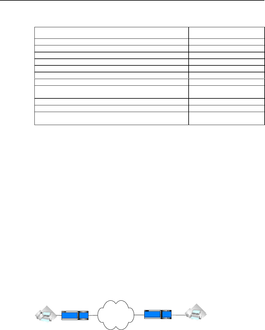
User Manual - Configuration Guide (Volume 3)
Versatile Routing Platform Chapter 2
IP Fax Configuration
2-6
Table VC-2-9 Monitoring and maintenance of IP Fax
Operation Command
Open all of the debugging information switches of ipfax debug ipfax all
Open the debugging information switch of function api of ipfax debug ipfax api
Open the debugging information switch of main task of ipfax debug ipfax cc
Open the debugging information switch of controller of ipfax debug ipfax controller
Open the debugging information switch of level 1 error message of ipfax debug ipfax error 1_level
Open the debugging information switch of level 2 error message of ipfax debug ipfax error 2_level
Open the debugging information switch of level 3 error message of ipfax debug ipfax error 3_level
Open the debugging information switch of all levels of error messages of
ipfax debug ipfax error all
Open the debugging information switch of T38 message of ipfax debug ipfax t38
Open the debugging information switch of cisco message of ipfax debug ipfax cisco
Open the debugging information switch for reading and writing fax data
between vpm module and voice card. debug vpm fax
2.4 Typical Configuration of IP Fax
The networking mode of IP Fax is basically the same as IP Phone. Thus, the functions
of IP Fax can be realized only when the telephone sets in the network of IP Phone are
replaced by facsimile machines. You can basically use the functions of IP Fax only if
you can configure IP Phone. The operation is easy to use.
1) Networking Requirements
Suppose a company headquarter located in Shenzhen plans to send/receive faxes
to/from its Beijing branch via IP network.
The fax number of its Beijing branch is 0101002, and the number of Shenzhen
headquarter is 07551001.
The IP address used to access to the Internet port through the router in Beijing is
1.1.1.2. The IP address used to access to the Internet port through the router in
Shenzhen is 1.1.1.1.
The facsimile machine in Beijing is connected with the second voice port on the router,
and the facsimile machine in Shenzhen is connected with the first voice port on the
router.
2) Networking Diagram
Internet
Router
0101002
port2 1.1.1.2
Beijing Router
1.1.1.1 port1
07551001
Shenzhen
Figure VC-2-2 Networking diagram for typical IP fax configuration
3) Configuration Procedure
The parameter settings for the router in Beijing is as follows:
Quidway(config)# dial-peer voice 1 voip
Quidway(config-peer-voip1)# destination 07551001
Quidway(config-peer-voip1)# session target ipv4:1.1.1.1

User Manual - Configuration Guide (Volume 3)
Versatile Routing Platform Chapter 2
IP Fax Configuration
2-7
Quidway(config-peer-voip1)# dial-peer voice 2 pots
Quidway(config-peer-pots2)# destination 0101002
Quidway(config-peer-pots2)# port 2
The parameter settings for the router in Shenzhen is as follows:
Quidway(config)# dial-peer voice 2 voip
Quidway(config-peer-voip2)# destination 0101002
Quidway(config-peer-voip2)# session target ipv4:2.2.2.2
Quidway(config-peer-voip2)# dial-peer voice 1 pots
Quidway(config-peer-pots1)# destination 07551001
Quidway(config-peer-pots1)# port 1
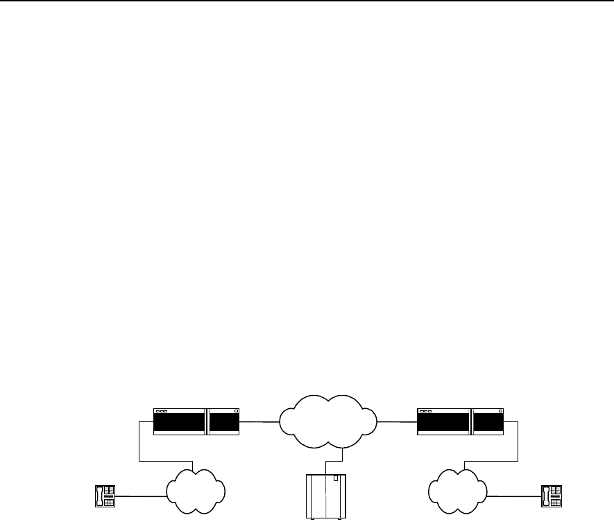
User Manual - Configuration Guide (Volume 3)
Versatile Routing Platform Chapter 3
E1 Voice Configuration
3-1
Chapter 3 E1 Voice Configuration
3.1 Overview of E1 Voice Configuration
3.1.1 Function of E1 Voice
E1 voice refers to the implementation of VoIP function over E1 line, so as to provide
voice transmission mode compatible with data transmission. In order to implement this
function, the corresponding E1 voice port needs to be provided on the router and also a
range of functions suitable for voice transmission over E1 line should be provided. The
networking that adopts E1 line for voice transmission is the same as the ordinary VoIP
networking applications, except that the connection between PSTN switch and the
router is through E1 trunk, and the signaling adopted for the line is R2 signaling (similar
to China No. 1 Signaling) or DSS1 subscriber signaling on ISDN PRI interface. The
basic networking is shown in the diagram below:
Telephone Telephone
IP network
IP voice gateway IP voice gateway
PSTN PSTN
Gate Keeper
E1 E1
Figure VC-3-1 Basic Structure of E1 Voice System
Adopting E1 voice mode, the router can provide more channels for voice
communication and supports integrated transmission of data and voice, greatly
enhancing the utilization rate of the router and the range of the services supported.
3.1.2 Usage of cE1/PRI Interface
The physical port of E1 voice is cE1/PRI interface, which is divided into 32 TSs (time
slots) numbered from 0 to 31. The following lists three methods to use this interface:
I. Interface not divided into TSs logically
When used as E1 interface, do not divide it into TSs logically and use the full capability
of the interface for data transmission. The bandwidth of the interface is 2Mbit/s (TSs 0
to 31) and its logical attribute is equal to the synchronous serial port with rate of 2Mbit/s.
On the interface, link layer protocols such as PPP, FR, LAPB, X.25 and HDLC, and
network protocols such as IP and IPX, are supported.

User Manual - Configuration Guide (Volume 3)
Versatile Routing Platform Chapter 3
E1 Voice Configuration
3-2
II. Interface divided into TSs logicailly & TS 16 not as special channel
When used as cE1 interface, all the other 31 TSs except TS0 can be divided into
several groups, with each group of TSs used as one interface (channel-group) after
being bound. Its logical attribute is equal to the synchronous serial ports of different
rates. On the interface, link layer protocols such as PPP, FR, LAPB, X.25 and HDLC,
and network protocols such as IP and IPX, are supported.
III. Interface divided into TSs logicailly & TS 16 as signaling channel
When DSS1 subscriber signaling is adopted, the interface is used as ISDN PRI
interface. Since TS16 is used as transmission connection signaling for D channel, you
can only bind TS 16 with any other TSs (except for TS0 and TS16) and use as one
interface (pri-group). Its logical attribute is the same as ISDN dial-up. On this interface,
PPP link layer protocol and network protocols such as IP and IPX are supported, and
parameters such as DDR can be configured.
When the upper layer uses R2 signaling, the contents transported in the TSs are: Every
32 TSs constitute a basic frame; every 16 basic frames constitute one multiframe; the
TS0 of every odd basic frame is used to transport the synchronous identity of the frame;
the TS16 of every odd basic frame is used to transport line signaling. In each
multiframe, the TS0 of the odd basic frame is used to transport FAS (Frame Alignment
Signal), and that of the even basic frame is used to transport NFAS (Non Frame
Alignment Signal). What transported on it is the state information about the links, which
provides control signaling for basic rate multiplexing. The 4 significant bits of the TS 16
of the first basic frame (Frame 0) of every multiframe are used to transport the
synchronous identity (Multiframe Alignment Signal (MFAS)) and the insignificant 4 bits
are used to transport asynchronous identity. The TS16 of the other 15 basic frames
transport the line state of every two TSs respectively, for instance, basic frame 1 is used
to transport the states of TS1 and TS16; basic frame 2 is used to transport the states of
TS2 and TS17.
3.1.3 Features of E1 Voice
I. Signaling modes supported
DSS1 subscriber signaling is supported on ISDN PRI interface and R2 signaling is
supported on E1 interface.
II. Protocols and standards supported
Support the relevant protocols under ITU-T H.323 frame and support the 5.3K and 6.3K
compression algorithms of G.711, G.729 and G.723.1 Annex A of ITU standard,
support CRC4 and non-CRC4 framing modes, support the two kinds of line coding of
HDB3 and AMI.
III. Support single stage dialing and two-stage dialing
It supports the two access functions of single stage dialing and two-stage dialing, which
adapts itself to the difference between various PBX exchanges in their transportation of
called numbers to the router. When one PBX exchange is transporting voice access
number to the router and the number is deleted, the router adopts single stage dialing
access mode to access the subscriber. If PBX exchange does not delete the access

User Manual - Configuration Guide (Volume 3)
Versatile Routing Platform Chapter 3
E1 Voice Configuration
3-3
number, the router will receive the complete dial number of the subscriber. In this case,
the router adopts two-stage dialing mode and releases prompt tone to guide the
subscriber to input other information.
IV. Integrated transmission of voice and data
When DSS1 subscriber signaling is adopted on ISDN PRI interface, Integrated
transmission of voice and data is supported. By Integrated transmission, it means that
data and voice are transported in the different B channels in one physical line.
3.2 E1 Voice Configuration
3.2.1 Configuration Task List of E1 Voice
The tasks of E1 voice configuration includes:
z Configure POTS dial-peer
z Configure VoIP dial-peer
z Configure the basic parameters of E1 interface
z Configure the voice port (E1 interface)
z Configure E1 voice R2 signaling
z Configure the basic parameters of ISDN PRI interface
z Configure voice port (ISDN PRI interface)
3.2.2 Configuring POTS dial-peer
POTS, the abbreviation of Plain Old Telephone Service, i.e., the ordinary telephone
service. Configuring POTS dial-peer is to establish relationship between the voice port
and the local telephone device. There are two basic configuration commands:
destination-pattern and port. Destination-pattern is used to define the destination
pattern associated with POTS dial-peer, while port relates POTS dial-peer to one
logical voice port, which is generally the voice port that the router connects to the local
exchange (PBX) through E1 line. Besides, the prefix may need to be configured for the
outgoing PBX subscribers.
Please perform the configuration of dial-peer voice pots in global configuration mode,
and perform other configurations in POTS dial-peer configuration mode.

User Manual - Configuration Guide (Volume 3)
Versatile Routing Platform Chapter 3
E1 Voice Configuration
3-4
Table VC-3-1 Configuration Commands of POTS dial-peer
Operation Command
Enter POTS dial-peer configuration mode dial-peer voice number pots
Delete POTS dial-peer no dial-peer voice number
Disable the truncating of the called number cancel-truncate
Truncate the called number no cancel-truncate
Configure the destination pattern of the dial-peer (telephone
number) destination-pattern string
Delete the destination pattern of the dial-peer (telephone number) no destination-pattern
Configure the access number of two-stage dialing incoming called-number number
Delete the access number of two-stage dialing no incoming called-number
Set the precedence of IP packet ip precedence priority-number
Recover the default value of the precedence of the IP packet no ip precedence
Configure the correspondence between POTS dial-peer and DS0
group logical voice port port e1-controller-number :ds0-group-number
Configure the correspondence between POTS dial-peer and
ISDN PRI group logical voice port port e1-controller-number :15
Cancel the correspondence between POTS dial-peer and logical
voice port no port
Configure the prefix of the outgoing number prefix string
Delete the prefix of the outgoing number no prefix
Disable the POTS dial-peer shutdown
Enable the POTS dial-peer no shutdown
Enable silence detection vad
Disable silence detection no vad
By default, no cancel-truncate (i.e. truncate the called number) and no vad (i.e.
disable silence detection) become effective.
The default value of configuration command ip precedence (the precedence of IP
packet) is 0.
3.2.3 Configuring VoIP dial-peer
VoIP is the abbreviation of Voice over IP. VoIP dial-peer is used to match telephone
number with IP address. There are two basic configuration commands: destination-
pattern and session target. The destination-pattern defines the telephone number
associated with VoIP dial-peer, while session target specifies the destination IP
address for VoIP dial-peer.
Please perform dial-peer voice voip in global configuration mode, and perform other
configurations in VoIP dail-peer (dial-peer) configuration mode.

User Manual - Configuration Guide (Volume 3)
Versatile Routing Platform Chapter 3
E1 Voice Configuration
3-5
Table VC-3-2 Configuration Commands of VoIP dial-peer
Operation Commands
Enter VoIP dial-peer configuration mode dial-peer voice number voip
Delete VoIP dial-peer no dial-peer voice number
Configure voice codec method codec { 1st-priority-level | 2nd-priority-level |
3rd-priority-level | 4th-priority-level } { g711alaw |
g711ulaw | g723r53 | g723r63 | g729r8 }
Recover the default value of voice codec method no codec { 1st-priority-level | 2nd-priority-level |
3rd-priority-level | 4th-priority-level }
Configure the destination pattern of dial-peer (telephone
number) destination-pattern string
Delete the destination pattern of the dial-peer (telephone
number) no destination-pattern
Set the precedence of IP packet ip precedence priority-number
Recover the default value of the precedence of IP packet no ip precedence
Set the session target of the dail-peer session target { ipv4:a.b.c.d | ras }
Delete the session target of the dial-peer no session target
Disable the VoIP dial-peer shutdown
Enable the VoIP dial-peer no shutdown
Configure H.323 gateway tech-prefix tech-prefix string
Delete H.323 gateway tech-prefix no tech-prefix
Enable silence detection vad
Disable silence detection no vad
By default, no tech-prefix (i.e. H.323 gateway tech-prefix not configured initially)
command becomes effective, and no vad (disable silence detection) command
becomes effective.
The default value of configuration command codec (voice coding and decoding
method) is g729r8. The default value of configuration command ip precedence (the
precedence of IP packet) is 0.
3.2.4 Configuring the Basic Parameters of E1 Interface
In order that the device on the two ends of E1 trunk will be synchronized in
communication, E1 clock source needs to be configured for the device on both ends. At
this stage, there are two ways to select the clock source: generating the clock by itself
and extracting the clock from the line.
When channel-group is successfully configured, the system will create the serial port
corresponding to the channel-group automatically. The number of the new serial port is
“(the number of the serial port where the channel group lies + the total number of the
serial ports): channel-group number”.
Please use commands controller e1 and interface serial in global configuration mode
and perform other configurations in E1 controller interface configuration mode.

User Manual - Configuration Guide (Volume 3)
Versatile Routing Platform Chapter 3
E1 Voice Configuration
3-6
Table VC-3-3 Configuration Commands of E1 Interface
Operation Command
Enter E1 controller interface configuration controller e1 port
Establish channel-group for the specified TS channel-group channel-group-no timeslots timeslots-
list
Delete specified channel-group no channel-group channel-group-no
Set clock source clock { line [ primary ] | internal }
Cancel clock source no clock
Configure framing mode framing { crc4 | no-crc4 }
Configure line coding mode linecode { ami | hdb3 }
Start loopback test loopback
Disable loopback test no loopback
Select interface mode using { e1 | ce1 }
Enter the serial port corresponding to the channel-group interface serial serial-no :channel-group-no
By default, no loopback (i.e. disable loopback test) becomes effective.
The default value of the configuration command clock (clock source) is line. The
default value of the configuration command framing (framing mode) is no-crc4. The
default value of the configuration command linecode (line coding mode) is hdb3. The
default value of the configuration command using (E1 interface mode) is ce1.
3.2.5 Configuring Voice Port (E1 Interface)
Before entering voice port (E1 interface) configuration mode, first DS0 group needs to
be created in E1 controller interface configuration mode. In this way, the system will
create the voice port corresponding to the DS0 group automatically.
Please use voice-port command in global configuration mode and perform other
configurations in voice port configuration mode.

User Manual - Configuration Guide (Volume 3)
Versatile Routing Platform Chapter 3
E1 Voice Configuration
3-7
Table VC-3-4 Configuration Commands of E1 Voice Port
Operation Command
Enter voice port configuration mode voice-port port-nunmber :ds0-group-number
Enable comfort noise setting comfort-noise
Disable comfort noise setting no comfort-noise
Establish PLAR mode connection for voice port connection plar telephone-number
Delete the PLAR connection of the voice port no connection plar
Configure the description information of the port description string
Delete the description information of the port no description
Enable echo cancellation function or set the time
coverage of echo cancellation sampling echo-cancel { enable | coverage coverage-time }
Cancel echo cancellation function or recover the default
value of the time coverage of echo cancellation sampling no echo-cancel { enable | coverage }
Set voice input gain input gain value
Recover the default value of voice input gain no input gain
Set echo cancellation to use non-linear processing
procedure non-linear
Cancel echo cancellation’s use of non-linear processing
procedure no non-linear
Configure voice output attenuation output attenuation value
Recover the default value of voice output attenuation no output attenuation
Disable the voice port shutdown
Enable the voice port no shutdown
By default, comfort-noise (i.e. enable comfort-noise setting) command becomes
effective and no connection plar (i.e. the system has not established PLAR mode
connection initially) command becomes effective, and non-linear (i.e. enable non-
linear processing procedure) becomes effective.
The default value of configuration command echo-cancel (enable echo cancellation) is
enable. The default value of command echo-cancel coverage (time coverage of echo
cancellation sampling) is 16ms. The default value of configuration command input
gain (voice input gain) is 0. The default value of configuration command output
attenuation (voice output attenuation) is 0.
3.2.6 Configuring E1 Voice R2 Signaling
I. Configuring DS0 group
DS0 is the logical voice port abstracted from the actual E1 port by defining the time slot
list, and it serves voice transmission. The time slots included in the DS0 group are all
used to transmit voice, while the other time slots not included still can serve data
information transmission. Only one DS0 can be defined on one E1 port. The R2
signaling configuration for E1 line is facilitated by configuring signaling type and the
relevant parameters of R2 signaling for each DS0. When DS0 group is successfully
configured, the system will create the voice port corresponding to the DS0 according to
the current E1 port number and DS0 group number. The voice port number is “E1 port
number: DS0 group number”.
For the commands in the table below, please use controller e1 in global configuration
mode and the others in E1 controller interface configuration mode.

User Manual - Configuration Guide (Volume 3)
Versatile Routing Platform Chapter 3
E1 Voice Configuration
3-8
Table VC-3-5 DS0 Configuration Commands of DS0 Group
Operation Command
Enter E1 controller interface configuration mode controller e1 port-number
Create DS0 of certain type ds0-group group-number timeslots timeslots-list type
{ e&m-fgb | e&m-immediate-start | fxs-loop-start |
r2-digital [ r2-compelled [ ani ] ] }
Delete the specified DS0 group no ds0-group group-number
By default, the system has not created any DS0 group.
II. Configuring Related Parameters of R2 Signaling
R2 signaling conforms to ITU-T recommendation, and is classified into line signaling
and register signaling, which can be used for national network and international
network. China No. 1 signaling is a subset of R2 signaling. The line signaling, which is
classified into forward and backward signaling, is mainly used to monitor the seizure,
release and block state of the trunk. The register signaling, also classified into forward
and backward signaling, adopts multi-frequency compelled mode to transmit address
information, the language bit and authentication bit of international call, echo
cancellation information, caller attribute and callee attribute information, and etc.
Please use cas-custom command in E1 controller interface configuration mode and
perform other configurations in R2 signaling configuration mode.

User Manual - Configuration Guide (Volume 3)
Versatile Routing Platform Chapter 3
E1 Voice Configuration
3-9
Table VC-3-6 Configuration Commands of R2 Signaling
Operation Command
Enter R2 signaling configuration mode cas-custom ds0-group-number
Configure the number of the numbers collected before
the caller number or the caller identity required caller-digits number
Recover the default value of the number of the
numbers collected no caller-digits
Set the debounce time of the line signaling debounce-time number
Recover the default value of the debounce time of the
line signaling no debounce-time
Specify a command by default default
Set the inversion mode of line signal invert-abcd A-bit B-bit C-bit D-bit
Recover the default value of the inversion mode of line
signal no invert-abcd
Set the code of KA signal ka number
Recover the default value of the code of KA signal no ka
Set the code of KD signal kd number
Recover the default value of the code of KD signal no kd
Set the latency of sending seizure acknowledgement
signal seizure-ack-time millseconds
Recover the default value of the latency of sending
seizure acknowledgement signal no seizure-ack-time
Set E1 trunk routing mode select-mode [ max | maxpoll | min | minpoll ]
Set the time interval to wait for various signals timeouts { kb | kd | nextnum | ringing | sendasw }
value
Recover the default value of the time interval to wait for
various signals no timeouts { kb | kd | nextnum | ringing | sendasw }
Set the direction of E1 trunk trunk-direction timeslots timeslot-list { in | out |
dual }
Recover the default value of the direction of E1 trunk no trunk-direction timeslots timeslot-list
Set the signal value of C and D signal bits unused-abcd A-bit B-bit C-bit D-bit
Recover the default value of the signal value of C and
D signal bits no unused-abcd
By default, comfort-noise (i.e., enable comfort-noise setting) command becomes
effective, and non-linear (i.e., enable non-linear processing procedure) command
becomes effective.
The default value of the configuration command caller-digits (the number required to
be collected before the caller number) is 1, and that for debounce-time (the
debounce-time of line signaling) is 40ms, and invert-abcd (the inversion mode of line
signaling) disabled, i.e., the value is 0 0 0 0. The default value of command ka (the
code of KA signal) is 1, and that for kd (the code of KD signal) is 3, the seizure-ack-
time (the latency of sending seizure acknowledgement signal) 100ms. The default
value of the command select-mode (E1 trunk routing mode) is min, and that of the
command timeouts kb (the time interval waiting for receiving KB signal) is 5000ms,
and timeouts kd (the time interval waiting for receiving KD signal) 5000ms. The default
value of the command timeouts nextnum (the time interval waiting for receiving next
MFC compelled digital signal) is 5000ms, and that for timeouts ringing (the time
waiting for the end of the ring) is 30000, and timeouts sendasw (the time interval
waiting for sending answer signal) 500. The default value of command trunk-direction
(the direction of E1 trunk) is dual, and that for unused-abcd (set the signal value of
signal bit C and D) is 1111.

User Manual - Configuration Guide (Volume 3)
Versatile Routing Platform Chapter 3
E1 Voice Configuration
3-10
3.2.7 Configuring the Basic Parameters of ISDN PRI Interface
If DSS1 subscriber signaling of ISDN PRI interface is adopted between the router and
the switch, the integrated transmission of voice and data is supported, in other words,
in one E1 trunk connecting the router and the switch, voice signal and data signal
occupy different B channels for transmission respectively. When the function of
integrated transmission of voice and data is adopted, it is required to configure DDR
dialing in the corresponding serial port of ISDN PRI group, so as to implement data
transmission.
After ISDN PRI group is successfully configured, the system will, on one hand,
generate the corresponding voice port of the PRI group according to the E1 port
number where the current PRI interface lies: the voice port number is “E1 port
number:15”; on another hand, the system will generate the corresponding serial port of
PRI group according to the current serial port number: the number of the new port is
“(the number of the serial port where PRI group lies + the total number of serial ports) :
15”.
After the channel-group is successfully configured, the system will create the
corresponding serial port of the channel-group automatically. The number of the new
serial port is “the number of the serial port where the channel-group lies + the total
number of the serial port)”.
Please use commands controller e1 and interface serial in global configuration mode,
and perform other configurations in E1 controller interface configuration mode.
Table VC-3-7 Configuration Commands of ISDN PRI Interface
Operation Command
Enter E1 controller interface configuration mode controller e1 port
Create channel-group for specified TS channel-group channel-group-no timeslots timeslots-list
Delete the specified channel-group no channel-group channel-group-no
Set clock source clock { line [ primary ] | internal }
Cancel clock source no clock
Configure framing mode framing { crc4 | no-crc4 }
Configure line coding mode linecode { ami | hdb3 }
Start loopback test loopback
Disable loopback test no loopback
Create PRI group pri-group [ timeslots timeslots-list ]
Delete the specified PRI group no pri-group
Enter the corresponding serial port of channel-group interface serial serial-no :channel-group-no
Enter the corresponding serial port of ISDN PRI group interface serial serial-no :15
By default, no channel-group (i.e. the system has not created channel-group for the
time slots initially.) command becomes effective, and no loopback (i.e. disable
loopback test) command becomes effective, and no pri-group (i.e. the system does
not create any PRI group initially.) command becomes effective.
The default value of configuration command clock (clock source) is line, and framing
(framing mode) no-crc4, and linecode (line coding mode) hdb3.

User Manual - Configuration Guide (Volume 3)
Versatile Routing Platform Chapter 3
E1 Voice Configuration
3-11
3.2.8 Configuring Voice Port (ISDN PRI Interface)
Before entering voice port (ISDN PRI interface) configuration mode, first the ISDN PRI
group needs to be created, so that the system will create the voice port corresponding
to the PRI group automatically.
Please perform voice-port configuration in global configuration mode and perform other
configurations in voice port configuration mode.
Table VC-3-8 Configuration Commands of ISDN Voice Port
Operation Command
Enter voice port configuration mode voice-port port-number :15
Enable comfort noise setting comfort-noise
Disable comfort noise setting No comfort-noise
Establish PLAR mode connection for voice port connection plar telephone-number
Delete the PLAR connection of the voice port No connection plar
Configure the description information of the port description string
Delete the description information of the port No description
Enable echo cancellation function or set the time coverage of
echo cancellation sampling echo-cancel { enable | coverage coverage-time }
Cancel echo cancellation function or recover the default
value of the time coverage of echo cancellation sampling no echo-cancel { enable | coverage }
Configure voice input gain input gain value
Recover the default value of voice input gain no input gain
Set echo cancellation to use non-linear processing procedure non-linear
Cancel echo cancellation’s use of non-linear processing
procedure no non-linear
Configure voice output attenuation output attenuation value
Recover the default value of voice output attenuation no output attenuation
Disable the voice port shutdown
Enable the voice port no shutdown
By default, comfort-noise (i.e. enable comfort noise setting) command becomes
effective, no connection plar (i.e. the system has not established PLAR mode
connection initially.) command becomes effective, and non-linear (i.e. start non-linear
processing procedure) command becomes effective.
The default value of configuration command echo-cancel (enable echo cancellation) is
enable, and echo-cancel coverage (the time coverage of echo cancellation sampling)
16ms, and input gain (voice input gain) 0, and output attenuation (voice output
attenuation) 0.
3.3 Monitoring and Maintenance of E1 Voice
I. Maintaining the MFC Channel and Circuit of the Specified TS
MFC channel is used to bear R2 register signaling, while the circuit is used to bear the
actual incoming and outgoing calls. You can perform maintenance operations such as
open, block and query to the MFC channel of the specified TS. You can perform
operations such as open, block, query and reset to the trunk circuit of the specified TS.
The operations of open and block are reverse process to each other.

User Manual - Configuration Guide (Volume 3)
Versatile Routing Platform Chapter 3
E1 Voice Configuration
3-12
Please use cas-custom command in E1 controller interface configuration mode and
perform other configurations in R2 signaling configuration mode.
Table VC-3-9 Operation & Maintenance Commands for MFC Channels and TSs
Operation Command
Enter R2 signaling configuration mode cas-custom ds0-group-number
Perform maintenance and operation to the MFC channel of the
specified TS mfc { block | open | query } timeslots timeslots-
list
Perform maintenance and operation to the trunk circuit of the
specified TS ts { block | open | query | reset } timeslots
timeslots-list
II. show Command Related to E1 Voice
Please use the following show commands to monitor in privileged mode.
Table VC-3-10 The show Commands of E1 Voice
Operation Command
Show the attribute of E1 controller port show controller e1 port-number
Show the configuration of voice port show voice-port port-number : { ds0-group-number | 15 }
Show the interface ISDN status show isdn status [ interface interface-name ]
Show the call statistics related to R2 signaling in RCV
module show rcv statistic r2
Show the call statistics of R2 signaling show r2 call-statistics
Show the relevant information of VoIP show voip { downqueue e1vi-bno | phy-statistic e1vi-
bno | upqueue e1vi-bno | version vpu-bno }
1) Show the attribute of E1 controller port
Quidway# show controller e1 0
E1 1-0 is up.
Applique type is Channelized E1 - 120 OHM balanced
Framing is NO-CRC4, Line Code is HDB3, Source Clock is Internal.
The above packets indicate that: E1 port is activated; the impedance of the trunk is 120;
the framing mode is no-crc4; the line code is HDB3; the clock is internal clock.
2) Show the configuration of voice port
Quidway# show voice-port 0:0
The voice port was ds0
connection type is PLAR, connection number:2001
The voice port's descrition:e1-port
echo cancel enable
echo cancel coverage 16
comfort noise enable
The above packets indicate that: the E1 voice port 0:0 is in DS0 group mode; PLAR
connection is adopted and the connection number is 2001; the voice port description is
e1-port; the echo cancellation function is enabled and the time coverage of echo
cancellation sampling is 16ms; comfort noise function is enabled.

User Manual - Configuration Guide (Volume 3)
Versatile Routing Platform Chapter 3
E1 Voice Configuration
3-13
Quidway# show voice-port 1:15
The voice port was pri
this voice port was not set connection
The voice port's descrition:
echo cancel enable
echo cancel coverage 16
music threshold is -70
input gain 0
output attenuation 0
non-linear
initial timeouts 10
inter-digits timeouts 10
The above packets indicate: the voice port is ISDN PRI mode; PLAR connection is not
adopted; voice port description is not specified; echo cancellation function is enabled;
the time coverage of echo cancellation sampling is 16ms; both input gain and output
attenuation are 0dB; echo cancellation uses non-linear processing procedure; the time
set for waiting for the first digit is 10s; the dial time interval between each number is
10s.
3) Show interface ISDN status
Quidway# show isdn status interface serial 1:15
Serial1:15 :
Layer 2 Status:
TEI = 0, State = AWAITING_ESTABLISHMENT
Layer 3 Status:
0 Active Layer 3 Call(s)
The above packets indicate that: the serial port corresponding to ISDN PRI interface is
serial1:15; Layer 2 protocol in on status of waiting for the setup of connection; there is
no activated call on layer 3.
4) Show the call statistics related to R2 signaling in RCV module
Quidway# show rcv statistic r2
Statistic between RCV and R2 :
{
Send_R2_ConnectReqAck_SUCCESS : 0
Send_R2_ConnectReqAck_FAIL : 0
Send_R2_ActiveAck_SUCCESS : 0
Send_R2_ActiveAck_FAIL : 0
Send_R2_Onhook : 0
Send_R2_Offhook : 0
Recv_R2_ConnectReq : 0
Recv_R2_Active_TD_IN : 0
Recv_R2_Active_TD_OUT : 0
Recv_R2_Active_ELSE : 0
Recv_R2_Release : 0

User Manual - Configuration Guide (Volume 3)
Versatile Routing Platform Chapter 3
E1 Voice Configuration
3-14
Recv_R2_Alert_AP_ALERTING : 0
Recv_R2_Alert_ELSE : 0
Recv_R2_Unknow : 0
}
The packets above show the interactive information between RCV module and R2
signaling, including the successful and failed number of the packets sent about the
connection request acknowledgement, the successful and failed number of the packets
sent about the activation acknowledgement, the number of the packets sent about
onhook and offhook, the number of the connection request packets received, the
number of the activation packets received, the number of the packets received about
release, alert, unknown and etc.
5) Show the call statistics of R2 signaling
Quidway# show r2 call-statistics
r2 signalling call statistics
30 drop from state TK_BLOCKED_BY_PEER
1 drop from state TKI_WAIT_CALLED_NUM
2 drop from state TKI_WAIT_VPU_ACTIVE_ACK
2 drop from state TKI_CALLED_ONHOOK
1 drop from state TKO_SEND_CALLED_NUM
2 drop from state TKO_RELEASE_GUARD
The above packets show the call statistics related to R2 signaling: the block of the
opposite end causes the drop of 30 calls; waiting for the caller number causes the drop
of 1 incoming call; waiting for the activation acknowledgement of the voice channel
causes the drop of 2 incoming calls; the onhook of the called number causes the drop
of 2 incoming calls; sending the called number causes the drop of 1 outgoing call;
releasing guard signal causes the drop of 2 outgoing calls.
6) Show the related information of VoIP
Quidway# show voip down-queue 5
V = 0,I = 0,P = 0,C = 0,E = E1VI_NULL_EVENT, B = 0
V = 0,I = 1,P = 0,C = 0,E = E1VI_NULL_EVENT, B = 0
……
V = 0,I = 255,P = 0,C = 0,E = E1VI_NULL_EVENT, B = 0
E1VI board 5 down interrupt queue is empty :
The above packets show the contents of the downstream interrupted queue between
E1 voice board and router motherboard: V denotes valid bit, I is the serial number, P
port number, C channel number, E event, and B blocked bit. The packets shown by
show voip up-queue is the same as that of show voip down-queue.
Quidway# show voip version 0
[Slot 1] VI_NULL Hardware Version is 1.0, Driver Version is 1.0
The packets above show the hardware version and driver version of VI board.
III. debug Commands Related to E1 Voice
Please use the following debug commands in privileged mode for monitoring and
maintenance.
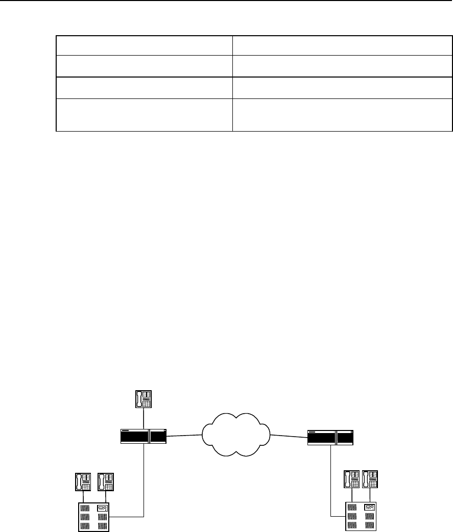
User Manual - Configuration Guide (Volume 3)
Versatile Routing Platform Chapter 3
E1 Voice Configuration
3-15
Table VC-3-11 debug Commands of E1 Voice
Operation Command
Enable the debugging information output between
RCV module and base layer R2 module debug rcv r2
Enable the debugging information output between
VPP module and base layer R2 module debug vpp r2
Enable the output of the corresponding debugging
information of R2 module debug r2 { all | dl controller e1-port-no timeslots-list | error |
event | fail-reason | fsm controller e1-port-no timeslots-list |
mfc controller e1-port-no timeslots-list | rcv | warning }
3.4 Typical Configuration Examples of E1 Voice
3.4.1 Router Connected to PBX through E1 Voice Port
I. Networking requirement
The telephones in Beijing and Shenzhen communicate with each other directly via IP
network using routers with voice function. The FXS (POTS) interface of Beijing router is
connected to the telephone directly and is connected to PBX exchange through E1
voice port. The Shenzhen router is connected to PBX exchange only through E1 voice
port. The communications signaling adopts R2 signaling and adopts single stage
dialing mode.
II. Networking Diagram
WAN WAN
2.2.2.2
Router_ Beijing WAN
1.1.1.1
010-1001010-1002
PBX
0755-2002
PBX
E1
Port0: 1
Beijing Shenzhen
Router_Shenzhen
0755-2001
010-1003
Port0
Port1:1
E1
Figure VC-3-2 Router Connected to PBX in E1 Mode (Single stage dialing)
III. Configuration Procedure
1) Parameters configuration of the Beijing-side router
! Configure DS0 group
Quidway(config)# controller e1 0

User Manual - Configuration Guide (Volume 3)
Versatile Routing Platform Chapter 3
E1 Voice Configuration
3-16
Quidway(config-if-E1-0)# ds0-group 1 timeslots 1-31 type r2-digital
! Set up the POTS dial-peer on FXS interface (telephone number 010-1003)
Quidway(config)# dial-peer voice 1003 pots
! Configure the destination pattern of the POTS dial-peer on FXS interface
Quidway(config-peer-pots1003)# destination-pattern 0101003
! Configure the POTS peer on FXS interface to correspond with logical port
Quidway(config-peer-pots1003)# port 0
! Create POTS dial-peer on E1 interface (telephone number 010-1001)
Quidway(config)# dial-peer voice 1001 pots
! Configure the destination pattern of the POTS dial-peer on E1 interface
Quidway(config-peer-pots1001)# destination-pattern 0101001
! Configure the POTS peer on E1 interface to correspond with logical port
Quidway(config-peer-pots1001)# port 0:1
! Create VoIP dial-peer
Quidway(config)# dial-peer voice 0755 voip
! Configure the destination pattern of VoIP dial-peer
Quidway(config-peer-voip755)# destination-pattern 0755....
! Configure VoIP peer to correspond with logical port
Quidway(config-peer-voip755)# session target ipv4:2.2.2.2
2) The parameter configuration of the Shenzhen-side router is similar to that of
Beijing-side.
! Configure DS0 group
Quidway(config)# controller e1 1
Quidway(config-if-E1-1)# ds0-group 1 timeslots 1-31 type r2-digital
! Create the POTS dial-peer on E1 interface (tel: 0755-2001 or 2002, etc.)
Quidway(config)# dial-peer voice 2001 pots
! Configure the destination pattern of POTS dial-peer on E1 interface
Quidway(config-peer-pots2001)# destination-pattern 0755....
! Configure the POTS peer on E1 interface to correspond with logical port
Quidway(config-peer-pots2001)# port 1:1
! Create VoIP dial-peer
Quidway(config)# dial-peer voice 010 voip
! Configure the destination pattern of VoIP dial-peer
Quidway(config-peer-voip10)# destination-pattern 010....

User Manual - Configuration Guide (Volume 3)
Versatile Routing Platform Chapter 3
E1 Voice Configuration
3-17
! Configure VoIP peer to correspond with logical port
Quidway(config-peer-voip10)# session target ipv4:1.1.1.1
3.4.2 Router Connected to PBX in ISDN PRI Mode
I. Networking requirement
The telephones in Beijing and Shenzhen communicate with each other directly via IP
network using routers with voice function. The FXS (POTS) interface of Beijing router is
connected to the telephone directly and is connected to PBX exchange through E1
voice port. The Shenzhen router is connected to PBX exchange only through E1 voice
port. The routers in both places are connected to the exchange by adopting ISDN PRI
interface DSS1 subscriber signaling and adopts single stage dialing mode.
II. Networking diagram
The networking diagram is similar to VC-3-2, except that ISDN PRI interface DSS1
subscriber signaling is adopted between PBX and the router.
III. Configuration procedure
1) Parameter configuration of the Beijing-side router
! Configure ISDN PRI group
Quidway(config)# controller e1 0
Quidway(config-if-E1-0)# pri-group
! Create POTS dial-peer on FXS interface (telephone number 010-1003)
Quidway(config)# dial-peer voice 1003 pots
! Configure the destination pattern of the POTS dial-peer on FXS interface (tel: 010-
1003)
Quidway(config-peer-pots1003)# destination-pattern 0101003
! Configure the POTS peer on FXS interface to correspond with the logical port
(telephone number 010-1003)
Quidway(config-peer-pots1003)# port 0
! Create the POTS dial-peer on ISDN PRI interface (telephone number 010-1001)
Quidway(config)# dial-peer voice 1001 pots
! Configure the destination pattern of POTS dial-peer on ISDN PRI interface (tel: 010-
1001)
Quidway(config-peer-pots1001)# destination-pattern 0101001
! Configure the POTS peer on ISDN PRI interface to correspond with logical port (tel:
010-1001)
Quidway(config-peer-pots1001)# port 0:15
! Create VoIP dail-peer

User Manual - Configuration Guide (Volume 3)
Versatile Routing Platform Chapter 3
E1 Voice Configuration
3-18
Quidway(config)# dial-peer voice 0755 voip
! Configure the destination pattern of the VoIP dial-peer
Quidway(config-peer-voip755)# destination-pattern 0755....
! Configure VoIP peer to correspond with logical port
Quidway(config-peer-voip755)# session target ipv4:2.2.2.2
2) The parameter configuration of the Shenzhen-side router is similar to that of
Beijing.
! Configure ISDN group
Quidway(config)# controller e1 1
Quidway(config-if-E1-1)# pri-group
! Create the POTS dial-peer on ISDN PRI interface (tel: 0755-2001 or 2002, etc.)
Quidway(config)# dial-peer voice 2001 pots
Configure the destination pattern of the POTS dial-peer on ISDN PRI interface (tel:
0755-2001 or 2002, etc.)
Quidway(config-peer-pots2001)# destination-pattern 0755....
! Configure the POTS peer on ISDN PRI interface to correspond with logical port (tel:
0755-2001 or 2002, etc.)
Quidway(config-peer-pots2001)# port 1:15
! Create VoIP dial-peer
Quidway(config)# dial-peer voice 010 voip
! Configure the destination pattern of VoIP dial-peer
Quidway(config-peer-voip10)# destination-pattern 010....
! Configure VoIP peer to correspond with logical port
Quidway(config-peer-voip10)# session target ipv4:1.1.1.1
3.4.3 Two-stage Dialing Configuration
I. Networking requirement
The telephones in Beijing and Shenzhen communicate with each other directly via IP
network using routers with voice function. The FXS (POTS) interface of Beijing router is
connected to the telephone directly and is connected to PBX exchange through E1
voice port. The Shenzhen router is connected to PBX exchange only through E1 voice
port. The communication signaling adopts R2 signaling. The subscribers of Beijing
PBX exchange adopt two-stage dialing to dial to Shenzhen: first dial 163, then dial the
called number according to the prompt tone in turn; Single stage dialing is adopted to
dial to Beijing from Shenzhen, i.e. dial the “called number” directly.
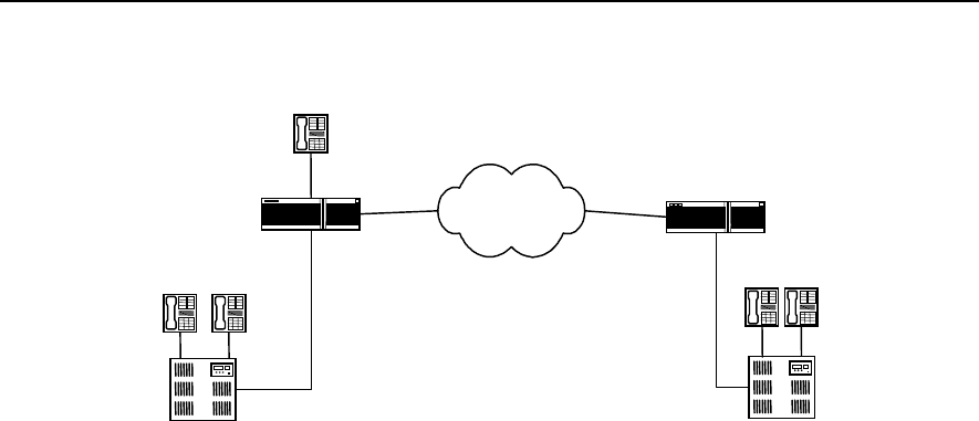
User Manual - Configuration Guide (Volume 3)
Versatile Routing Platform Chapter 3
E1 Voice Configuration
3-19
II. Netwoking diagram
WAN WAN
2.2.2.2
Router_ Beijing WAN
1.1.1.1
010-1001010-1002
PBX
0755-2002
PBX
E1
Port0:1
Beijing Shenzhen
Router_Shenzhen
0755-2001
010-1003
Port0
Port1:1
E1
Subscriber in Beijing dials 163,
and then inputs in sequence
the called number 07552001
according to the prompts.
Figure VC-3-3 Router Connected to PBX in E1 Mode (Two-stage dialing)
III. Configuration procedure
1) Configuration of Beijing-side PBX exchange
First modify the configuration of Beijing-side PBX exchange, so that PBX will not delete
the access number 163, ensuring that PBX sends the number 163 to Beijing-side
router.
2) Parameter configuration of Beijing-side router
! Configure DS0 group
Quidway(config)# controller e1 0
Quidway(config-if-E1-0)# ds0-group 1 timeslots 1-31 type r2-digital
! Create the POTS dial-peer on FXS interface (telephone number 010-1003)
Quidway(config)# dial-peer voice 1003 pots
! Configure the destination pattern of the POTS dial-peer on FXS interface
Quidway(config-peer-pots1003)# destination-pattern 0101003
! Configure the POTS peer on FXS interface to correspond with logical port
Quidway(config-peer-pots1003)# port 0
! Create the POTS dial-peer on E1 interface (Tel: 010-1001)
Quidway(config)# dial-peer voice 1001 pots
! Configure the destination pattern of the POTS dial-peer on E1 interface
Quidway(config-peer-pots1001)# destination-pattern 0101001
! Configure the POTS peer on E1 interface to correspond with logical port
Quidway(config-peer-pots1001)# port 0:1
! Configure two-stage dialing
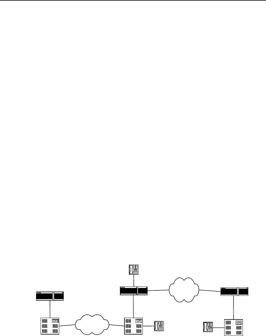
User Manual - Configuration Guide (Volume 3)
Versatile Routing Platform Chapter 3
E1 Voice Configuration
3-20
Quidway(config-peer-pots1001)# incoming called-number 163
! Create VoIP dial-peer
Quidway(config)# dial-peer voice 0755 voip
! Configure the destination pattern of VoIP dial-peer
Quidway(config-peer-voip755)# destination-pattern 0755....
! Configure VoIP peer to correspond with logical port
Quidway(config-peer-voip755)# session target ipv4:2.2.2.2
3) Configuration of Shenzhen-side PBX exchange
Modify the configuration of Shenzhen-side PBX exchange, so that PBX deletes access
number 163, ensuring that PBX only send the called number input by the subscriber to
Shenzhen-side router.
4) The parameter configuration of Shenzhen-side router is the same as that of
Shenzhen-side router specified in section 3.4.1.
3.4.4 Transmission of Data and Voice Simultaneously
I. Networking requirement
The telephones in Beijing and Shenzhen communicate with each other directly via IP
network using routers with voice function. The FXS (POTS) interface of Beijing router is
connected to the telephone directly and is connected to PBX exchange through E1
voice port. The Shenzhen router is connected to PBX exchange only through E1 voice
port. The communications signaling adopts R2 signaling. The routers in Beijing and
Shanghai are connected through PSTN network and implement data transmission in
DDR mode.
II. Networking diagram
WAN WAN
2.2.2.2
Router_Beijing WAN
1.1.1.1
PBX PBX
E1
Port0:1
Beijing Shenzhen
Router_Shenzhen
0755-2001
010-1003
Port0
Port1:1
E1
PSTN
Shanghai
PBX
Router_Shanghai
010-1001
Figure VC-3-4 Integrated Transmission of Data and Voice
III. Configuration procedure
1) Parameter configuration of Beijing-side router

User Manual - Configuration Guide (Volume 3)
Versatile Routing Platform Chapter 3
E1 Voice Configuration
3-21
First perform voice configuration following the configuration procedure of Beijing-side
router specified in section 3.4.2 step by step, and then configure DDR dialing in the
corresponding port of ISDN PRI interface. Please refer to the relevant DDR sections for
details.
2) Parameter configuration of Shanghai-side router
Configure DDR dialing in the port corresponding to Beijing-side router. Please refer to
the relevant DDR sections for details.
3) Parameter configuration of Shenzhen-side router
Please perform voice configuration according to parameter configuration of
Shenzhen-side router specified in section 3.4.2.
3.5 Fault Diagnosis and Troubleshooting of E1 Voice
Fault 1: Failure in establishing connection when switch-side subscriber calls router-side
subscriber
Troubleshooting: please follow the following steps:
z First, use show running command to check that all the TSs are used when
configuring signaling. Please make sure that the TSs the exchange uses is the
same as the TSs configured for the router. Connection cannot be established, if
the TSs that the exchange uses for outgoing calls are not used in the configuration
of the router.
z If there is no dial tone in the call duration, please check that the exchange has sent
the outgoing trunk office code to the router and that office code and access
number are configured for the telephone number on the router. Generally,
connection cannot be established, if the exchange also sends the outgoing trunk
office code and the telephone number on the router-side does not add the office
code or is not configured with access number. You can either delete the outgoing
trunk office code in the exchange-side configuration, or configure access number
on router-side.
Fault 2: Using R2 signaling, the router fails to establish connection with subscribers on
the exchange-side.
Troubleshooting: please follow the following steps:
First, use show running command to check that the trunk mode of the router
corresponds with that of the exchange configuration. In other words, if the exchange-
side is outgoing trunk, the router-side should be incoming trunk or bi-directional trunk; if
the exchange-side is incoming trunk, the router-side should be out-going trunk or bi-
directional trunk. If the trunk mode of the router-side is incoming trunk, the subscribers
on router-side can only call in, and cannot call out.

User Manual - Configuration Guide (Volume 3)
Versatile Routing Platform Chapter 4
GK Client Configuration
4-1
Chapter 4 GK Client Configuration
4.1 Overview of GK Client
IP telephone uses Internet as the medium to transmit voice information. IP telephone
GateWay (GW for short) lies between Public Switched Telephone Network (PSTN) and
Internet access sites. It compresses the voice signal on PSTN network and transports it
to the opposite end IP telephone gateway via Internet. Meanwhile, it receives the IP
packet from Internet and decompresses it to restore to voice signal of PSTN network.
The implementation of IP telephone function on router expands the function of the
router, which indicates the trend of the gradual expansion from data service to voice
service.
As defined in ITU-T recommendation, GateKeeper (GK for short) is a H.323 entity that
can provide such functions as address translation, admission control, bandwidth
control and management, area management, security check, call control signaling and
call management, and sometimes routing control and billing functions, for the H.323
terminal, GW or some Multipoint Control Unit (MCU) of Local Area Network or Wide
Area Network. In an area managed by GK, to all the calls, GK not only provides call
service control and also serves as the central control point.
According to the composition of the entity that implements complete GK function, it can
be classified into Client end and Server end. Taking router as its hardware medium, GK
Client entity generally performs the configuration of IP voice gateway function for the
router through the command line interface, and interacts with GK Server by RAS
signaling, thus enable GK Server to provide services such as address translation,
admission control, bandwidth management, and the management of router IP voice
gateway. GK Server can be implemented on SUN workstation or routers.
4.2 Configuration of GK Client
4.2.1 Configuration Task List of GK Client
The configuration tasks of GK Client include:
z Configure one interface as H.323 gateway interface
z Activate or deactivate GK Client function
z Configure alias of the gateway
z Configure the GK Server name and address corresponding to the gateway
z Configure tech-prefix
z Configure GK interconnection mode
4.2.2 Configuring One Interface as H.323 Gateway Interface
The router communicates with GK Server as voice gateway device. It needs to specify
the interface that communicates with GK server for the router. The interface specified is
H.323 gateway interface. Ethernet port, serial port, etc., can all become H.323 gateway

User Manual - Configuration Guide (Volume 3)
Versatile Routing Platform Chapter 4
GK Client Configuration
4-2
interface. Only after one interface is specified as H.323 gateway interface, can the
function of CK Client be activated and can GK Client register to GK Server.
Please perform the following configurations in interface configuration mode.
Table VC-4-1 Specifying One Interface as H.323 Gateway Interface
Operation Command
Specify one interface as H.323 gateway interface h323-gateway voip interface
Cancel one interface as H.323 gateway interface no h323-gateway voip interface
By default, no interface is specified as H.323 gateway interface.
4.2.3 Activating or Deactivate GK Client Function
Only when one interface is successfully configured as H.323 gateway interface, can
GK Client function be activated. When the H.323 gateway interface is re-specified or
the relevant parameters (such as gateway alias and corresponding Gatekeeper name)
of other gateways are modified, you should activate GK Client function anew, so that
the information related to Client stored in GK Server is updated timely.
Please perform the following configurations in global configuration mode.
Table VC-4-2 Activate or Deactivate GK Client Function
Operation Command
Activate GK Client function gateway
Deactivate GK Client function no gateway
By default, GK Client function is deactivated.
4.2.4 Configuring Gateway Alias
Gateway alias is used to register at GK Server and identify gateway. One gateway can
have only one alias.
Please perform the following configurations in interface configuration mode.
Table VC-4-3 Configure Gateway Alias
Operation Command
Configure gateway alias h323-gateway voip h323-id namestring
Delete gateway alias no h323-gateway voip h323-id [ namestring ]
By default, the gateway alias is blank, i.e. no gateway alias configured.
4.2.5 Configure the GK Server Name and Address
When the GK Client of the router is activated, GK Client will automatically register the
relevant information of the gateway to GK Server. Therefore, it needs to configure
User Manual - Configuration Guide (Volume 3)
Versatile Routing Platform Chapter 4
GK Client Configuration
4-3
information of GK server, such as the IP address and name, to find the right GK Server
device,.
Please perform the following configurations in interface configuration mode.
Table VC-4-4 Configure the GK Server Name and Address Corresponding with the Gateway
Operation Command
Configure the GK Server and IP address
corresponding with the gateway h323-gateway voip id gk-name ipaddr gk-ipaddress [ ras-port ]
Delete the GK Server and IP address
corresponding with the gateway no h323-gateway voip id [ gk-name [ ipaddr gk-ipaddress [ ras-
port ] ] ]
By default, no GK Server name and IP address are specified corresponding with the
gateway. When using the command to configure, the default value of RAS
communication port of GK Server is 1719.
4.2.6 Configuring Tech-Prefix
Tech-prefix is used mainly for the convenience of identifying the gateway type of GK
Server. One gateway can be configured with 10 tech-prefixes at most.
Please perform the following configurations in interface configuration mode.
Table VC-4-5 Configure Tech-Prefix
Operation Command
Configure tech-prefix h323-gateway voip tech-prefix string
Delete tech-prefix no h323-gateway voip tech-prefix [ string ]
By default, there is not any tech-prefix.
4.2.7 Configuring GK Interworking Mode
As the device produced by different IP telephone device manufactures are different in
their specific implementations of H.323 protocol, there is problem of interworking
between the gateways and gatekeepers (GK Server) and between gatekeepers made
by different manufacturers. If the voice gateway of the router is to communication with
GK Server made by other manufacturers in the normal way, the matched interworking
mode needs to be adopted. So far in this case, there are two manufacturers of GK
Server involved, i.e., Cisco Inc., and Huawei Technologies.
Please perform the following configurations in interface configuration mode.
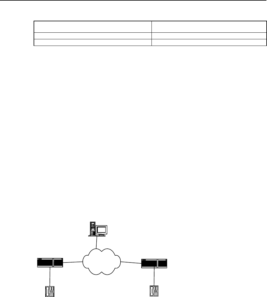
User Manual - Configuration Guide (Volume 3)
Versatile Routing Platform Chapter 4
GK Client Configuration
4-4
Table VC-4-6 Configure GK Interworking Mode
Operation Command
Configure GK interworking mode h323-gateway voip support-mode { cisco | huawei }
Recover the default value of GK interworking mode no h323-gateway voip support-mode
Be default, the GK interworking mode is cisco mode.
4.3 Typical Configuration Examples of GK Client
I. Networking requirement
The telephones in Beijing and Shenzhen communicate with each other directly via IP
network using routers with voice function, and perform the dynamic resolution from the
telephone number to IP address by virtue of GK.
The serial port 0 of Beijing-side router is H.323 gateway interface. The IP address of
serial port 0 is 1.1.1.1; the alias of the interface is Beijing-gsw; the name of the
corresponding gatekeeper is gk-center; the address of the gatekeeper is 3.3.3.3; the
RAS port number is 1719, and the tech-prefix is specified as 1#. The serial port 1 of
Shenzhen-side router is H.323 gateway interface; the IP address is 2.2.2.2; the alias of
the interface is shenzhen-gw; the other configurations are the same as those of
Beijing-side.
II. Networking diagram
GK Server
WAN serial1
2.2.2.2
Beijing-gw serial0
1.1.1.1
Port0
Beijing Shenzhen
Shenzhen-gw
010-1001
Port1
0755-2001
3.3.3.3
Figure VC-4-1 Networking Mode of GW and GK Combination
III. Configuration Procedure
1) Parameter configuration of Beijing-side router
! Create the POTS dial-peer on FXS interface
Quidway(config)# dial-peer voice 1001 pots
Quidway(config-peer-pots1001)# destination-pattern 0101001

User Manual - Configuration Guide (Volume 3)
Versatile Routing Platform Chapter 4
GK Client Configuration
4-5
Quidway(config-peer-pots1001)# port 0
! Create VOIP dial-peer
Quidway(config)# dial-peer voice 0755 voip
Quidway(config-peer-voip755)# destination-pattern 0755....
Quidway(config-peer-voip755)# session target ras
! Specify Serial0 as H.323 gateway interface
Quidway(config-if-Serial0)# ip address 1.1.1.1 255.255.255.0
Quidway(config-if-Serial0)# h323-gateway voip interface
! Configure gateway alias and the corresponding GK name and IP address
Quidway(config-if-Serial0)# h323-gateway voip h323-id beijing-gw
Quidway(config-if-Serial0)# h323-gateway voip id gk-center ipaddr 3.3.3.3 1719
! Configure tech-prefix
Quidway(config-if-Serial0)# h323-gateway voip tech-prefix 1#
! Configure GK interworking mode
Quidway(config-if-Serial0)# h323-gateway voip support-mode huawei
! Activate GK Client function
Quidway(config)# gateway
Quidway(config-gateway)#
2) Parameter configurations of Shenzhen-side are similar to those of Beijing-side
! Create POTS dial-peer on FXS interface
Quidway(config)# dial-peer voice 2001 pots
Quidway(config-peer-pots2001)# destination-pattern 07552001
Quidway(config-peer-pots2001)# port 1
! Create VOIP dial-peer
Quidway(config)# dial-peer voice 010 voip
Quidway(config-peer-voip10)# destination-pattern 010....
Quidway(config-peer-voip10)# session target ras
! Specify Serial1 as H.323 gateway interface
Quidway(config-if-Serial1)# ip address 2.2.2.2 255.255.255.0
Quidway(config-if-Serial1)# h323-gateway voip interface
! Configure gateway alias and the corresponding GK name and IP address
Quidway(config-if-Serial1)# h323-gateway voip h323-id shenzhen-gw
Quidway(config-if-Serial1)# h323-gateway voip id gk-center ipaddr 3.3.3.3 1719
! Configure tech-prefix

User Manual - Configuration Guide (Volume 3)
Versatile Routing Platform Chapter 4
GK Client Configuration
4-6
Quidway(config-if-Serial1)# h323-gateway voip tech-prefix 1#
! Configure GK interworking mode
Quidway(config-if-Serial1)# h323-gateway voip support-mode huawei
! Activate GK Client function
Quidway(config)# gateway
Quidway(config-gateway)#
4.4 Fault Diagnosis and Troubleshooting of GK Client
Fault 1: The register of GW on GK Server end fails.
Troubleshooting: Please follow the following steps:
z First, use ping command to check that it can interwork with GK Server on network
layer.
z Use
show running-config command to check that gateway command takes
effect.
z Check that GK Server end gatekeeper is activated.
Check that GK Server end has configured the area.

User Manual - Configuration Guide (Volume 3)
Versatile Routing Platform Chapter 5
IPHC Configuration
5-1
Chapter 5 IPHC Configuration
5.1 Overview of IPHC
IPHC (IP Header Compression) is the method to classify and compress packet such as
IP, TCP and UDP, according to a series of header compression algorithms specified in
relevant RFC documents, so as to enhance the transmission rate of voice, video and
large packet over low-speed network. Currently, IPHC is mainly applied to the serial
links running such protocols as PPP, FR and HDLC and carrying large amount of voice
information.
As described in RFC2507, the packets need to be compressed can be classified into
the following categories:
1) IP header + TCP header
2) IP header + UDP header
3) IP header + UDP header + RTP header
Among them, (RTP) Realtime Transmit Protocol is an application layer protocol lies
above TCP/UDP, which is mainly used to transmit audio, video and simulated data
information.
The implementation of IPHC depends on the various existing compression algorithms,
whose main concepts are to compress the header since many fields of the headers do
not change or change regularly in the course of one-time connection. It divides header
into TCP and NON_TCP type, and further divides them into smaller categories.
Extracting the unchanged fields or the fields that change regularly from the header of
the same packet type, it does not transmit or only transmit the changed values of those
fields, thus achieving the purpose of compressing the length of the whole packet.
IPHC defines the two ends of the link as compressor and non-compressor end
respectively. The packet processing procedure is described as below:
Compressor: According to the classification method in RFC2507 document, after it
classify and compresses the packets, the compressor notifies the decompressor
through different packet protocol numbers and makes the decompressor perform
different compression in accordance with the corresponding protocol number. If the
compressor receives fault-reporting packet CONTEXT_STATE sent from the
decompressor, it will mark some location digits in the context storage table according to
the information in the packet to identify the faulty packet flow and will performs faulty
processing accordingly. For example, when the next packet arrives, it will transmit
packets to the decompressor in the complete format to help the latter update context
storage table and to implement re-synchronization, etc.
Decompressor: It performs decompression according to the different types of packets
transmitted from the compressor, and restores them into complete packets. If it finds
that there is fault in packet decompression process, it will either discard the faulty
packet or generate CONTEXT_STATE fault-reporting packet according to the actual
conditions.
By using IP header compression on low-speed serial link, it can implement:
z Enhance the packet Interactive Response Speed
z Reduce the transmission cost of header, enabling small packet to achieve high
link transmission quality and saving bandwidth resource
z Reduce the packet discard rate on lossy links

User Manual - Configuration Guide (Volume 3)
Versatile Routing Platform Chapter 5
IPHC Configuration
5-2
5.2 IPHC Configuration
5.2.1 Configuration Task List of IPHC
The configuration tasks of IPHC include:
z Enable/disable RTP header compression
z Configure the maximum connection number of RTP header compressions
z Configure the maximum connection number of TCP header compressions
z Configure the enabling of the Cisco-compatible RTP header compression
z Configure the removal of udp_chk field in the UDP header.
5.2.2 Enable/disable RTP header compression
When RTP header compression is enabled, TCP header compression will be enabled
accordingl. If the RTP header compression is disabled, the TCP header compression
will also be disabled.
Please make the following configuration in the interface configuration mode.
Table VC-5-1 Enable/Disable RTP header compression
Operation Command
Enable RTP header compression ip rtp header-compression
Disable RTP header compression no ip rtp header-compression
By default, the interface will not perform RTP header compression on the packet.
It should be pointed out for notice here,
1) The subscriber must configure RTP header compression command on both ends
of the links at the same time.
2) After TCP header compression is enabled, fast forwarding will not be performed
on the packet compressed.
3) After the configuration is completed, only when the shutdown and no shutdown
operation are performed on the interface can the configuration take effect.
5.2.3. Configure the Max. Connection Number of RTP Header Compressions
The subscriber can specify the maximum connection number on an interface that
performs RTP header compression.
Please perform the following configurations in interface configuration mode.
Table VC-5-2 Configure the maximum connection number of RTP header compression
Operation Command
Configure the maximum connection number of RTP header
compression ip rtp compression-connections number
Restore the default value of the maximum connection number of
RTP header compression no ip rtp compression-connections
By default, the maximum connection number of TCP header compression that the
interface allows is 16. The value ranges from 4 to 1000.

User Manual - Configuration Guide (Volume 3)
Versatile Routing Platform Chapter 5
IPHC Configuration
5-3
Notice: After the configuration completes, please perform one “shutdown” and “no
shutdown” operation to take effect the configuration.
5.2.4 Configure the Max. Connection Number of TCP Header Compressions
The subscriber can specify the maximum connection number on an interface that
performs TCP header compression.
Please perform the following configurations in interface configuration mode.
Table VC-5-3 Configure the maximum connection number of TCP header compression
Operation Command
Configure the maximum connection number of TCP
header compression ip tcp header-compression
Restore the default value of the maximum connection
number of TCP header compression no ip tcp header-compression
By default, the maximum connection number of TCP header compression that the
interface allows is 16. The value ranges from 4 to 256.
Notice: After the configuration completes, please perform one “shutdown” and “no
shutdown” operation to take effect the configuration.
5.2.5 Configure the Cisco-compatible RTP header compression
Please perform the following configurations in interface configuration mode.
Table VC-5-4 Enable/Disable the Cisco-compatible RTP header compression
Operation Command
Enable the Cisco-compatible RTP Header Compression ip rtp header-compression cisco-format
Disable the Cisco-compatible RTP Header Compression no ip rtp header-compression cisco-format
By default, Cisco-compatible RTP header compression is enabled.
5.2.6 Configure the deleting of udp_chk field from UDP header
The udp_chk field in UDP header can be set to 0, in other words, ignore UDP
checksum field when performing header compression. In this way, 2-byte length in the
header is saved.
Please perform the following configurations in interface configuration mode.
Table VC-5-5 Configure Deleting/Resetting the udp_chk Field in UDP Header
Operation Command
Delete the udp_chk field in UDP header ip rtp header-compression delete-udpchk
Reset the udp_chk field in UDP header no ip rtp header-compression delete-udpchk
By default, the udp_chk field in UDP packet field is set to 0.

User Manual - Configuration Guide (Volume 3)
Versatile Routing Platform Chapter 5
IPHC Configuration
5-4
5.3 Monitoring and Maintenance of IPHC
Table VC-5-6 Monitoring and Maintenance of IPHC
Operation Command
Show the statistics of TCP header compression show ip tcp header-compression
[ interface-type interface-number ]
Clear the storage table items of TCP header compression clear ip tcp header-compression
[ interface-type interface-number ]
Show the statistics of RTP header compression show ip rtp header-compression
[ interface-type interface-number ]
Clear the storage table items of RTP header compression clear ip rtp header-compression
[ interface-type interface-number ]
Enable the debugging information of TCP header debug ip tcp head-compression
Enable the debugging information of RTP header debug ip rtp head-compression
1) Show the statistics of TCP header compression.
Quidway# show ip tcp header-compression serial 0
TCP/IP header compression statistics:
Interface Serial0:
Rcvd: 0 total, 0 compressed, 0 errors
0 dropped, 0 buffer copies, 0 buffer failures
Sent: 430 total 429 compressed,
15122 bytes saved, 139318 bytes sent
1.10 efficiency improvement factor
Connect:16 rx slots, 16 tx slots, 1 long searches, 1 misses
99% hit ratio, five minute miss rate 0 misses/5mins, 0 max.
2) Show the statistics of RTP header compression.
Quidway# show ip rtp header-compression serial 0
RTP/UDP/IP header compression statistics:
Interface Serial0:
Rcvd: 0 total, 0 compressed, 0 errors
0 dropped, 0 buffer copies, 0 buffer failures
Sent: 430 total 429 compressed,
15122 bytes saved, 139318 bytes sent
1.10 efficiency improvement factor
Connect: 16 rx slots, 16 tx slots, 1 long searches, 1 misses
99% hit ratio, five minute miss rate 0 misses/5mins, 0 max.
The above information displays such parameters as the number of RTP packet
received and transmitted on Sercial0, the number of the compressed RTP packets, the
number of the bytes saved and the efficiency improvement factors.

How Are We Doing
Let us share your comments with respect to the contents, formats and wording of this
manual. Your feedback can be of great value in helping us improve our document. Please
use a copy of these two pages for your comments, and fax to: +86-755-6540035
Documentation Development Department.
1. Please rate the effectiveness of this document in the following areas:
Excellent Good Fair Poor
Ease of Use
Clarity
Completeness
Accuracy
Organization Structure
Appearance
Examples
Illustrations
Overall Satisfaction
2. Please check the ways you feel we could improve this document:
Improve the overview/introduction Make it more brief/concise
Improve the table of contents Add more step-by-step procedures
Improve the organization structure Add more troubleshooting info.
Include more figures Make it less technical
Add more examples Add more reference aids
Add more details Improve the index
Please provide details for the suggested improvement:
3. What did you like most about this document?

4. Feel free to write any comments below or on an attached sheet.
5. It is highly appreciated for any specific mistakes you have found (this page may be sent to
us separately).
Mistake Suggested Correction Page &
Line No.
If we may contact you concerning your comments, please complete the following:
Name:______________________ Tel: _____________________________
Company:________________________________ Date:________________
Address:_______________________________________________________
