Huf Baolong Electronics Bretten TSSTSC Trigger Transmitter User Manual System description TSS 2nd Generation c
Huf Electronics Bretten GmbH Trigger Transmitter System description TSS 2nd Generation c
User Manual

TSS 2. Generation
Tire Safety System TSS 2nd. Generation
Dept. BEE
Dokument Nr.:
Document no.:
Änderungsstand:
Status of
modification:
Index:
Index:
3530.001.002.00.27
00 c
Systembeschreibung TSS
System description TSS
freigegeben am /date of release
17/01/07
Titel: Systembeschreibung TSS
Title: System description TSS
Dokument Nr.:
3530.001.002.00.27
Document no:
Projekt:
TSS 2. Generation
Project: Tire Safety System TSS 2nd. Generation
Current status:
Index:
Index:
Änd.stand:
Status of
modification:
Beschreibung:
Description
Erstellt / Datum:
Prepared / date:
Geprüft / Datum:
Checked / date:
Freigegeben /
Datum:
Released / date:
c 00 Revision regarding RE G2.3 Köninger
15/01/07
Birringer
16/01/07
Saric
17/01/07
Revision service
Index:
Index:
Änd.stand:
Status of
modification:
Beschreibung:
Description
Erstellt / Datum:
Prepared / date:
Geprüft / Datum:
Checked / date:
Freigegeben /
Datum:
Released / date:
b 00 315MHz components included Saric
03/09/06
Saric
03/09/06
Saric
03/09/06
a 00 First version
Saric/
8/26/05
Birringer/
8/26/05
Saric/
8/31/05

TSS 2. Generation
Tire Safety System TSS 2nd. Generation
Dept. BEE
Dokument Nr.:
Document no.:
Änderungsstand:
Status of
modification:
Index:
Index:
3530.001.002.00.27
00 c
Systembeschreibung TSS
System description TSS
freigegeben am /date of release
17/01/07
Section 15.19: Labelling requirements
This device complies with Part15 of the FCC Rules.
Operation is subject to the following two conditions:
(1) this device may not cause harmful interference, and
(2) this device must accept any interference received, including interference that may cause undesired
operation.
Section 15.21: Information to the user
The user manual or instruction manual for an intentional or unintentional radiator shall caution
the user that changes or modifications not expressly approved by the party responsible for compliance could
void the user’s authority to operate the equipment.
IC statement according to RSS210
5.11 User Manual
Operation is subject to the following two conditions:
(1) this device may not cause interference, and
(2) this device must accept any interference, including interference that may cause undesired operation of the
device

TSS 2. Generation
Tire Safety System TSS 2nd. Generation
Dept. BEE
Dokument Nr.:
Document no.:
Änderungsstand:
Status of
modification:
Index:
Index:
3530.001.002.00.27
00 c
Systembeschreibung TSS
System description TSS
freigegeben am /date of release
17/01/07
Contents:
1
SYSTEM AND FUNCTIONAL DESCRIPTION ................................................................................................. 5
1.1
S
YSTEM DESCRIPTION
.................................................................................................................................................5
2
FUNCTIONAL DESCRIPTION ............................................................................................................................ 6
3
WARNING ALGORITHM.....................................................................................................................................8
3.1
W
ARNING LIMIT
“M
INIMUM PRESSURE
” .....................................................................................................................8
3.2
W
ARNING LIMIT
“N
OMINAL PRESSURE MINUS RELATIVE DEVIATION
” (N
OMINAL PRESSURE
–
X
%) ..........................8
4
SYSTEM COMPONENTS...................................................................................................................................... 8
4.1
C
ONTROL UNIT
............................................................................................................................................................8
4.1.1
Installation area.................................................................................................................................................9
4.1.2
Temperature range.............................................................................................................................................9
4.1.3
Voltage Range....................................................................................................................................................9
4.1.4
Current consumption .........................................................................................................................................9
4.1.5
Occupancy of the CAN control unit:..................................................................................................................9
4.1.6
Occupancy of the K bus control unit: .............................................................................................................. 10
4.1.7
CAN bus connection.........................................................................................................................................10
4.1.8
K bus connection.............................................................................................................................................. 10
4.2
W
HEEL ELECTRONIC
.................................................................................................................................................10
4.2.1
Installation area...............................................................................................................................................11
4.2.2
Versions ...........................................................................................................................................................11
4.2.3
Temperature.....................................................................................................................................................11
4.2.4
Pressure ...........................................................................................................................................................12
4.2.5
Service Life.......................................................................................................................................................12
4.2.6
Environmental requirements............................................................................................................................ 12
4.2.7
Mechanical specification .................................................................................................................................13
4.2.8
Measurement specification ..............................................................................................................................13
4.2.9
Specification for HF transmitter ...................................................................................................................... 13
•
Transmitting power.................................................................................................................................................. 14
4.2.10
Block diagram wheel electronics .....................................................................................................................14
4.3
D
IGITAL
A
NTENNA
....................................................................................................................................................15
4.3.1
Installation Area ..............................................................................................................................................15
4.3.2
General Dimensions and Values......................................................................................................................15
4.3.3
Temperature ranges.........................................................................................................................................15
4.3.4
Voltage supply..................................................................................................................................................15
4.3.5
Current consumption .......................................................................................................................................15
4.3.6
Environmental conditions ................................................................................................................................15
4.3.7
TSS BUS communication with TSS control unit............................................................................................... 16
4.3.8
Connection occupancy, sleeve strip ................................................................................................................16
4.3.9
Block diagram..................................................................................................................................................16
4.3.10
Assembly ..........................................................................................................................................................17
4.4
T
RIGGER
T
RANSMITTERS
..........................................................................................................................................18
4.4.1
Temperatur / temperature ................................................................................................................................ 18
4.4.2
Mechanische Anforderungen / mechanical requirements................................................................................18
4.4.3
Voltage Range..................................................................................................................................................18
4.4.4
CurrentConsumption........................................................................................................................................ 18

TSS 2. Generation
Tire Safety System TSS 2nd. Generation
Dept. BEE
Dokument Nr.:
Document no.:
Änderungsstand:
Status of
modification:
Index:
Index:
3530.001.002.00.27
00 c
Systembeschreibung TSS
System description TSS
freigegeben am /date of release
17/01/07
4.4.5
Frequenz / frequency........................................................................................................................................18
4.4.6
Modulation / modulation..................................................................................................................................18
4.4.7
Physikalische Schnittstelle / physical link........................................................................................................19
4.4.8
Protokoll / protocol.......................................................................................................................................... 19
4.4.9
Diagnose / diagnosis........................................................................................................................................ 19
4.4.10
Stecker / connector........................................................................................................................................... 19
4.4.11
Environmental Qualification............................................................................................................................19
4.4.12
Schematic Representation of the Trigger Transmitters.................................................................................... 20

TSS 2. Generation
Tire Safety System TSS 2nd. Generation
Dept. BEE
Dokument Nr.:
Document no.:
Änderungsstand:
Status of
modification:
Index:
Index:
3530.001.002.00.27
00 c
Systembeschreibung TSS
System description TSS
freigegeben am /date of release
17/01/07
1 System and functional description
1.1
System description
The Tire Safety System (TSS) controls and monitors tire pressures.
The system comprises the following components:
1 TSS control unit
4 sets of wheel electronics including valve
1 digital antenna
4 trigger transmitters
The wheel electronics mounted inside the tire measures tire pressure and temperature at regular intervals and
transfers the values telemetrically via a HF transmission line to a reception antenna. The current pressure and
temperature values can be requested specifically via the trigger function. In the receiver antenna, the radio data
telegram is decoded and transferred to the control unit as a digital signal. The control unit evaluates the received
data and forwards the information to the driver as required. This provides the driver with information on the
necessary tire pressure or tire tension adjustments.
The benefits offered by the tire pressure control system are:
• Safety
An early warning in case of fast pressure loss is given.
"Blow-outs" caused by excessive flexing and driving too fast on inadequate tire pressure are avoided.
The driver is prompted to adjust the tire pressure where necessary.
• Comfort
Tire handing is made simple. Using the filling equipment at the fuel station and removing the valve cap is
only necessary for correcting the tire pressure.
• New tire developments
Tires with limp-home features avoid having to change a wheel immediately and render the spare wheel
superfluous. They do, however, require permanent monitoring of the tire pressure.
• Service life and economy
Tire wear is minimized through correct air pressure.

TSS 2. Generation
Tire Safety System TSS 2nd. Generation
Dept. BEE
Dokument Nr.:
Document no.:
Änderungsstand:
Status of
modification:
Index:
Index:
3530.001.002.00.27
00 c
Systembeschreibung TSS
System description TSS
freigegeben am /date of release
17/01/07
2 Functional description
The wheel electronics are mounted within the tires and measure tire pressure, temperature and wheel
electronics. The measured data is sent from the wheel via a transmitter in the wheel electronics. A system with
relatively seldom measured data transfer is adequate for tire pressure monitoring provided it features the
additional option of detecting sudden pressure loss. This enables the electronics in the wheel to be designed for
minimum power draw and battery operation.
All wheel electronics have their own code (ID) that is forwarded with the data at each transfer. The HF transfer
occurs in the 433 MHz range or, referred to as the ISM range and/or in some countries in the 315 MHz range.
The trigger functionality is achieved by a 125kHz LF channel.
The control unit calls up the wheel electronics via the trigger transmitters every 54 s ( a random generator with a
jitter of 25ms to 175ms ensures that no periodic signal is generated) to send data messages.
Tire pressure and wheel electronics temperature are also measured every 3 seconds. When a pressure loss
> 0.2 bar on the last sent pressure value is detected, the wheel electronics switch immediately to fast-send
mode. In this situation, the wheel electronics measure and send every 0.8 seconds.
The TSS measures and transfers considerably more data than is necessary to ensure reliable basic function. It
can therefore use a data transfer path that is not assigned for the error-free transfer of each individual data
protocol. Using the trigger function, an implausible and/or non-received data message can be requested again
from the corresponding wheel electronics.
The data sent by the wheel electronics is received via the digital antenna and is decoded. The decoded data is
transferred onwards to the control unit via a digital interface.
The control unit evaluates the received data and forwards the information to the driver information system as
required. This provides the driver with information on the necessary tire pressure or tire tension adjustments.
The main functional characteristics of the control unit are:
- A central warning algorithm and an algorithm for the wheel manager
- The vehicle-specific connection for the power supply system and manufacturer-specific operation and
display philosophy
The essential feature of wheel management is the self-learning system with automatic individual wheel detection
and the detection of the corresponding installed positions (wheel position detection).
Thanks to fast triggering of the wheel electronics when Ignition is ON, the system detects a flat tire well before
the start of a journey.
TSS 2. Generation
Tire Safety System TSS 2nd. Generation
Dept. BEE
Dokument Nr.:
Document no.:
Änderungsstand:
Status of
modification:
Index:
Index:
3530.001.002.00.27
00 c
Systembeschreibung TSS
System description TSS
freigegeben am /date of release
17/01/07
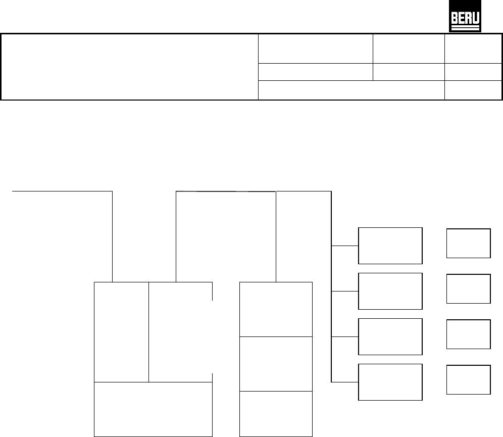
Figure 1: Block diagram, TSS system of the second generation
CAN bus
For Driver
Information
System
CAN
Interface
TSS-Bus
Interface
Function
s
oftware
TSS-Bus
Interface
Function
software
HF receiver
TSS
control unit
TSS-bus
Antenna
WE 1
WE 2
WE 3
WE 4
Trigger 1
Trigger 2
Trigger 3
Trigger4

TSS 2. Generation
Tire Safety System TSS 2nd. Generation
Dept. BEE
Dokument Nr.:
Document no.:
Änderungsstand:
Status of
modification:
Index:
Index:
3530.001.002.00.27
00 c
Systembeschreibung TSS
System description TSS
freigegeben am /date of release
17/01/07
3 Warning algorithm
The system monitors a nominal pressure, which is set by the operator, and a fixed set minimum warning
pressure. The higher value in each case is used to generate the breakdown warning.
The driver instructs the system to accept the current pressure values as the nominal pressure by using the
“Reset”. The reset is triggered by pressing a key or selecting a menu item.
3.1 Warning limit “Minimum pressure”
At this warning limit, a check is made against the minimum warning pressure P
Warning_MinimumPressure
, which is
programmed into the system as a fixed value.
The minimum warning pressure amounts to 2.6bar abs plus an accuracy reserve of 0.1bar.
The corresponding warning bit is set, if the measured pressure lies below this threshold twice in succession.
3.2 Warning limit “Nominal pressure minus relative deviation”
(Nominal pressure – x %)
This warning limit is calculated from the nominal pressure less a relative deviation of 25% of the nominal
pressure. The nominal pressure is specified by the driver.
Again here an accuracy reserve of 0.1 bar is added to the warning limit.
The corresponding warning bit is set, if the measured pressure lies below this threshold twice in succession.
4 System components
The system components of the TSS system are described below
4.1 Control unit
The control unit consists of a printed circuit board with microcontroller with interfaces for CAN- or K bus and
TSS-Bus.
The software is based on an OSEK Operation System. The tire information received from the digital antenna is
recorded and evaluated in the control unit. The pressure information and, if applicable, the warning information,
is forwarded via the CAN bus to the display systems in the vehicle.
The information from the digital antenna is transferred to the control unit via a so-called TSS Bus
communication. The control unit is the Bus master here, while the antenna or the trigger transmitters work as
slaves. The control unit interrogates the digital antenna at set intervals with respect to radio messages. The
trigger transmitters are contacted in sequence, in order to give them orders with respect to trigger commands
that are to be carried out. The control unit also supplies the supply voltage to the trigger transmitters and the
antenna.
The most important details of the control unit are described below.