Huffy Portable Basketball System 211260A User Manual To The 114973aa 7d6b 1614 85dd 02f07de6c8c3
User Manual: Huffy Portable Basketball System to the manual
Open the PDF directly: View PDF ![]() .
.
Page Count: 15
110/01 P/N 211260A
printed on recycled paper
WARNING
FAILURE TO FOLLOW THESE WARNINGS MAY RESULT
IN SERIOUS INJURY AND/OR PROPERTY DAMAGE.
Owner must ensure that all players know and follow
these rules for safe operation of the system.
• DO NOT HANG on the rim or any part of the system
including backboard, support braces or net.
• During play, especially when performing dunk type
activities, keep player's face away from the backboard, rim
and net. Serious injury could occur if teeth/face come in
contact with backboard, rim or net.
• Do not slide, climb, shake or play on base and/or pole.
• After assembly is complete, fill system completely with
water or sand and stake to the ground. Never leave system
in an upright position without filling base with weight, as
system may tip over causing injuries.
• When adjusting height or moving system, keep hands and
fingers away from moving parts.
• Do not allow children to move or adjust system.
• During play, do not wear jewelry (rings, watches, necklaces,
etc.). Objects may entangle in net.
• Surface beneath the base must be smooth and free of
gravel or other sharp objects. Punctures cause leakage and
could cause system to tip over.
• Keep organic material away from pole base. Grass, litter,
etc. could cause corrosion and/or deterioration.
• Check pole system for signs of corrosion (rust, pitting,
chipping) and repaint with exterior enamel paint. If rust has
penetrated through the steel anywhere, replace pole
immediately.
• Check system before each use for proper ballast, loose
hardware, excessive wear and signs corrosion and repair
before use.
• Check system before each use for instability.
• Do not use system during windy and/or severe weather
conditions; system may tip over. Place system in the
storage position and/or in an area protected from the wind
and free from personal property and/or overhead wires.
• Never play on damaged equipment.
• See instruction manual for proper installation and
maintenance.
• When moving system, use caution to keep mechanism from
shifting.
• Keep pole top covered with cap at all times.
• Do not allow water in tank to freeze. During sub-freezing
weather add non-toxic antifreeze, sand or empty tank
completely and store. (Do not use salt.)
•While moving system, Do not allow anyone to stand or sit
on base or have added ballasting on base.
• Do not leave system unsupervised or play on system when
wheels are engaged for moving.
• Use Caution when moving system across uneven surfaces.
System may tip over.
• Use extreme caution if placing system on sloped surface.
System may tip over more easily.
201246 2/99
In the U.S.:1-800-558-5234 and Canada: 1-800-284-8339
211249 02/00
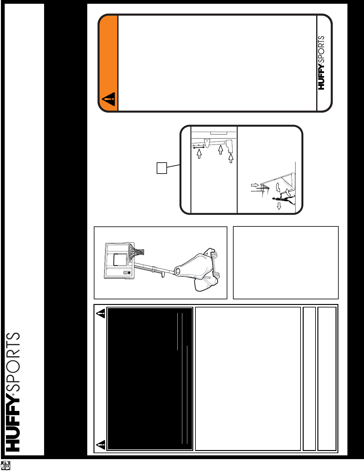
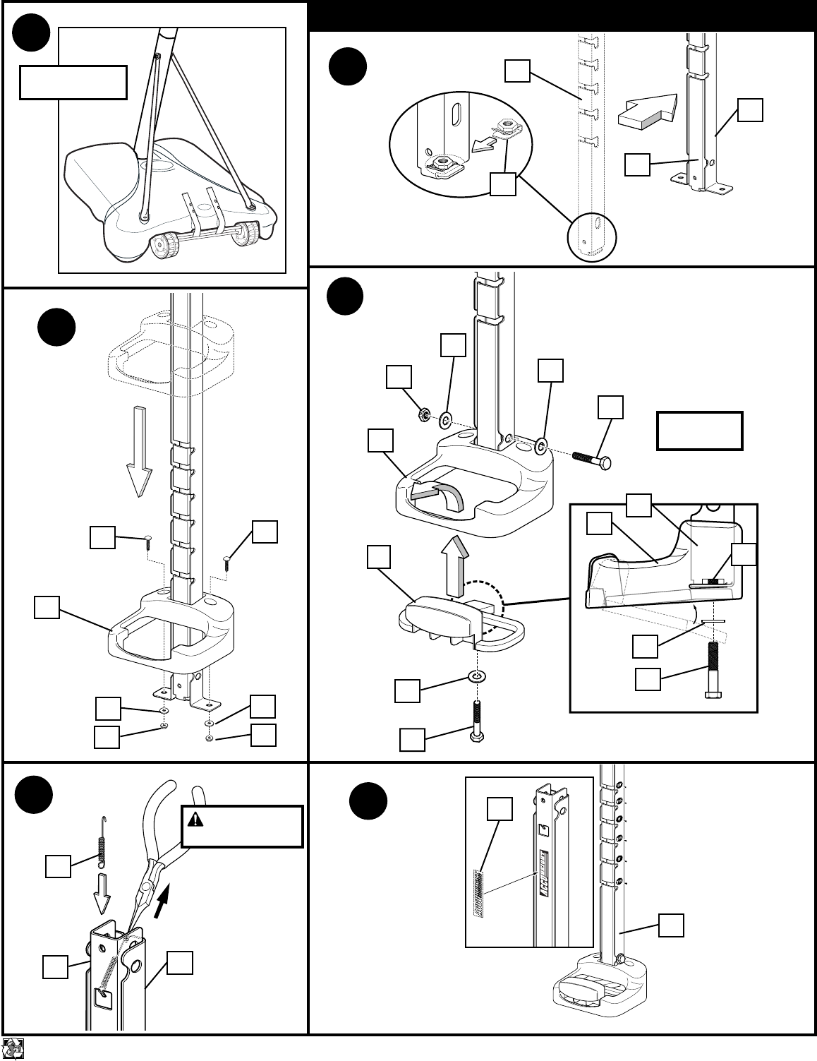
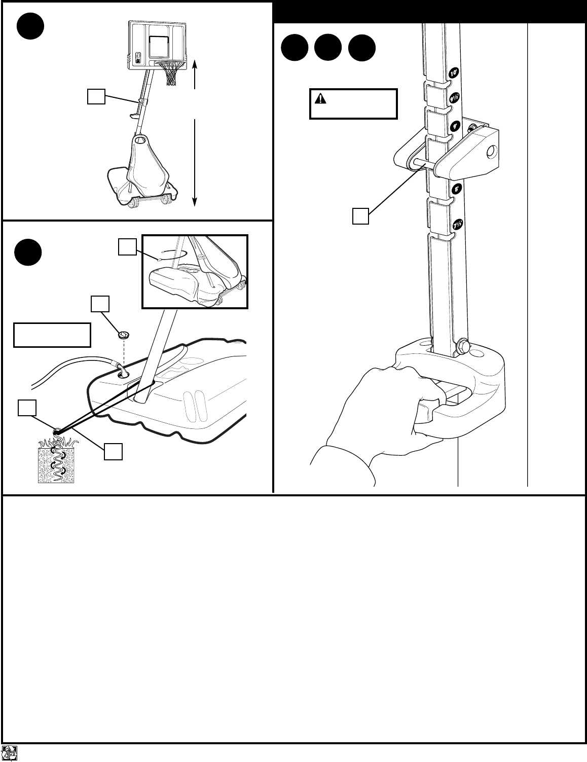
MOVING SYSTEM
1. Adjust basketball backboard
height to lowest position.
2. Rotate handle forward until
wheels engage ground.
3. Move basketball system to
desired location.
4. Rotate handle back to original
position.
5. Reattach ground restraint and
check system for stability.
HEIGHT ADJUSTMENT
1
2
3
TO ADJUST BACKBOARD:
1. Grasp handle and depress lever.
2. Push toward pole while holding
lever. Raise or lower to desired
height while pushing forward on
handle.
3. Release handle making sure that
horizontal pin is locked into slot.
1
32
4
Toll-Free Customer Service Number for U.S: 1-800-558-5234, For Canada: 1-800-284-8339, For Europe: 00 800 555 85234 (Sweden: 009 555 85234),
For Australia: 1-800-333 061 - Internet Address: http://www.huffysports.com
Most injuries are caused by misuse and/or not following instructions.
Use caution when using this system.
• If using a ladder during assembly, use extreme caution.
• Two (2) people are recommended for this operation.
• Check base regularly for leakage. Slow leaks could cause system to
tip over unexpectedly.
• Seat the pole sections properly (if applicable). Failure to do so could
allow the pole sections to separate during play and/or transport of the
system.
• Climate, corrosion or misuse could result in system failure.
• Minimum operational height is 6'6" (1.98 m) to the bottom of
backboard.
• This equipment is intended for home recreational use only and NOT
excessive competitive play.
• Read and understand the warning label affixed to pole. Label is
shown on page 1.
• The life of your basketball pole depends on many conditions. The
climate, placement of the pole, the location of the pole, exposure to
corrosives such as pesticides, herbicides or salts are all important.
• If technical assistance is required, contact Huffy Sports.
• Adult supervision is recommended when adjusting height.
FAILURE TO FOLLOW THESE SAFETY INSTRUCTIONS MAY
RESULT IN SERIOUS INJURY, PROPERTY DAMAGE AND WILL
VOID WARRANTY.
Owner must ensure that all players know and
follow these rules for safe operation of the system.
To ensure safety, do not attempt to assemble this system without
following the instructions carefully. Proper and complete assembly,
use and supervision is essential for proper operation and to reduce
the risk of accident or injury. A high probability of serious injury
exists if this system is not installed, maintained, and operated
properly. Check entire box and inside all packing material for parts
and/or additional instructional material. Before beginning
assembly, read the instructions and identify parts using the
hardware identifier and parts list in this document.
For more information on assembly, placement, proper use and
maintenance, visit The American Basketball Council website at
http://www.smarthoops.com.
SAFETY INSTRUCTIONS
77
REQUIRED TOOLS AND
MATERIALS:
• Two People
• Tape Measure
• Wood Board (Scrap)
• Wrenches: (Two) 7/16, 1/2, 9/16,
3/4, (9/16 Deep Socket w/Ext.
Recommended); (One) 3/8 or small
adjustable wrench; (One) 1/4 or
small adjustable wrench
• Sawhorse or Support Table
• Step Ladder 8 ft. (2.4 m)
• Garden Hose or Sand (300-325 lb.)
(136-147 kg)
• Hammer
• Tape
• Needle Nose Pliers
• Safety Goggles
© COPYRIGHT 2000 by HUFFY SPORTS
WRITE IN YOUR MODEL NUMBER:___________ Customer Service Center • N53 W24700 South Corporate Circle • Sussex, WI 53089 • U.S.A.
Portable Basketball System with Elevator Owner’s Manual
IMPORTANT! In U.S. and Canada only:
Have questions?...don’t go back to the store!
We appreciate your purchasing one of our many fine products. We are sure that you will be very satisfied with your selection. Although great care and effort have been taken, occasionally problems may occur.
To ensure prompt and correct handling of any problems, or to answer any questions, please contact our Toll-Free Customer Service Number listed below. Service will be quicker if you have your Model Number
(found on carton) and assembly instructions ready when calling. PLEASE WRITE YOUR MODEL NUMBER IN THE SPACE PROVIDED ABOVE.
NOTICE TO ASSEMBLERS
ALL Huffy Sports basketball Systems,
including those used for DISPLAYS,
MUST be assembled and ballasted with
sand or water according to instructions.
Failure to follow instructions could result
in SERIOUS INJURY. It is NOT
acceptable to devise a makeshift weight
system.
The NBA and individual NBA member team identifications
reproduced on this product are trademarks and copyrighted
designs, and/or other forms of intellectual property, that are the
exclusive property of NBA Properties, Inc. and the respective
NBA member teams and may not be used, in whole or in part,
without the written consent of NBA Properties, Inc.
A Huffy Company
2
P/N 211260A 10/01 printed on recycled paper
WARRANTY CARD:
Please remember to complete your product
registration form on-line at:
www.huffysports.com/warrantycard
or mail-in the enclosed postcard.
PARTS LIST (See Hardware Identifier)
Item Qty. Part No. Description
1 1 914822 Top Pole Section, Black
2 1 904811 Middle Pole Section, Black
3 1 903407 Bottom Pole Section, Black
4 1 200188 Rod, 3/8 x 5-1/4 Long Zinc
5 1 202822 Eyebolt, 3/8–16 x 3-3/4 Long
6 1 200117 Tank
7 1 202821 Disk, 2–3/4 O.D. x .188 Thick
8 6 203063 Lock Nut, Nylon Insert, 3/8–16
9 2 906410 Struts, Base
10 1 202662 Bolt, 5/16-18 x 4-1/2 Long
11 11 203218 Washer, Flat, 5/16 x 7/8 O.D.
12 1 203220 Lock Nut, Nylon Insert, 5/16-18
13 1 200516 Vinyl, Bolt Cover, 5/16
14 2 203798 Bolt, Hex Flange, 5/16-18 x 1-1/2 Long
15 19* 203100 Lock Nut, Whiz, 5/16-18
16 3 206327 Axle Rod, .461 O.D. x 4-1/4 Long
17 3 226401 Wheel 4” Diameter
18 1 200123 Upper Pivot Bracket
19 1 200512 Bolt, Hex Head,3/8-16 x 3-1/2 Long
20 14* 203232 Washer, 3/8 I.D., x 3/4 O.D.
21 1 206252 Bolt, Hex Head, 3/8-16 x 1 Long
22 1 206948 Lower Pivot Bracket
23 1 203330 Bolt, Hex Head, 3\8-16 x 4-1/2 Long
24 2 200122 Hinge Tubes
25 1 906608 Wheel Bracket
26 4 203103 Bolt, Carriage, 5/16-18 x 2 Long
27 2 202808 Wheel 6” Diameter
28 1 206940 Axle, .461 O.D. x 21 Long
29 2 206938 Push Caps
30 1 206956 Disc, Plastic, 5” O.D. x .0625 Thick
31 1 204839 Tinnerman Nut
32 1 904816 Inner Channel
33 1 904815 Outer Channel
34 1 204813 Handle, Height Adjustment
35 2 203217 Bolt, Carriage, 5/16-18 x 1.5 Long
36 1 203679 Bolt, Hex Head, 3/8-16 x 2 Long
37 3 201124 Lock Nut, Hex, 3/8-16
38 1 204814 Trigger, Height Adjustment
39 1 203589 Bolt, Hex Head, 5/16-18 x 1-1/4 Long
40 1 201125 Ratchet Spring
41 1 204809 Label, Accuheight
42 4 265601 Bolt, Carriage, 5/16-14 x 3-1/2 Long
Item Qty. Part No. Description
43 2 204840 Pin, 3 x 3/8
44 2 204841 Spring, Silver
45 1 204819 Bracket, Pole Mount
46 2 203053 Bolt, Carriage, 5/16-18 x 4 Long
47 1 206990 Reinforcement Bracket
48 1 204811 Spring Cover, Handle Left Side
49 1 204812 Spring Cover, Handle Right Side
50 1 206263 Bolt, Carriage, 5/16-18 x 3 Long
51 2 201129 Spacer, Metal, .5 O.D. x .402 I.D. x 1.8 Long
52 2 201088 Board Bracket
53 1 240017 Bolt, Hex Head, 1/4-20 x 2-1/4 Long
54 1 206360 Bolt, Hex Head, 3/8-16 x 2.625 Long
55 1 203493 Lock Nut, Hex Center-lock, 1/4-20
56 2 904821 Elevator Tube, Lower (Long)
57 6 204847 Bolt, Hex Head, 1/2-13 x 9-1/2 Long
58 7 206340 Lock Nut, Hex Head, 1/2-13
59 4 201682 Spacer, Black, .56 I.D. x .683 O.D. x 1.88 Long
60 4 201611 Bolt, Hex Flange, 5/16-18 x 3 Long
61 1 900741 Slam Jam Bracket, Black
62 2 203108 Bolt, Carriage, 5/16-18 x 2.5 Long
63 2 904807 Elevator Tubes, Upper (Short)
64 1 207103 Pole Cap
65 1 201139 Bolt, Hex Head, 1/2-13 x 4.5 Long
66 2 201654 Triangle Plate
67 8 202862 Spacer, Plastic, 1/2 I.D., 1-1/4 Long
68 2 204837 Spring
69 1 203796 Bolt, “Tee” 3/8 - NC x 5 Long
70 1 Rim
71 1 203234 Bracket Reinforcement, Slam Jam
72 1 203472 Spring, Black
73 1 203470 Washer, Flat 5/8 I.D. x 1-1/2 O.D.
74 1 203795 Nut, Special 3/8-NC
75 4 201611 Hex Flange Bolt 5/16-18 x 3 Long
76 1 204281 Net
77 1 211249 Label, Height and Moving
78 1 202438 Rope, Nylon Double Looped Tie Down
79 1 203124 Stake, Tie Down
80 1 206219 Cap, Tank-Black
81 12 200121 Clip, Net Holder
82 1 200119 Front Cover
*You may have extra parts with this model
10/01 P/N 211260A
3
printed on recycled paper
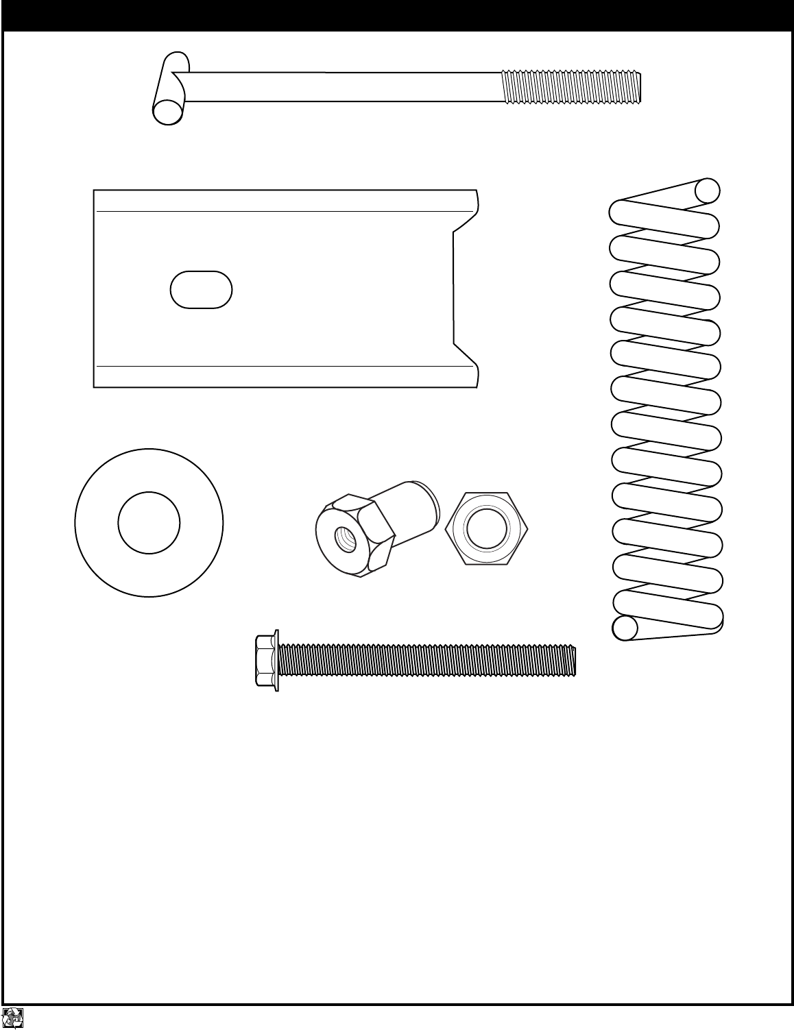
HARDWARE IDENTIFIER (CONTINUED)
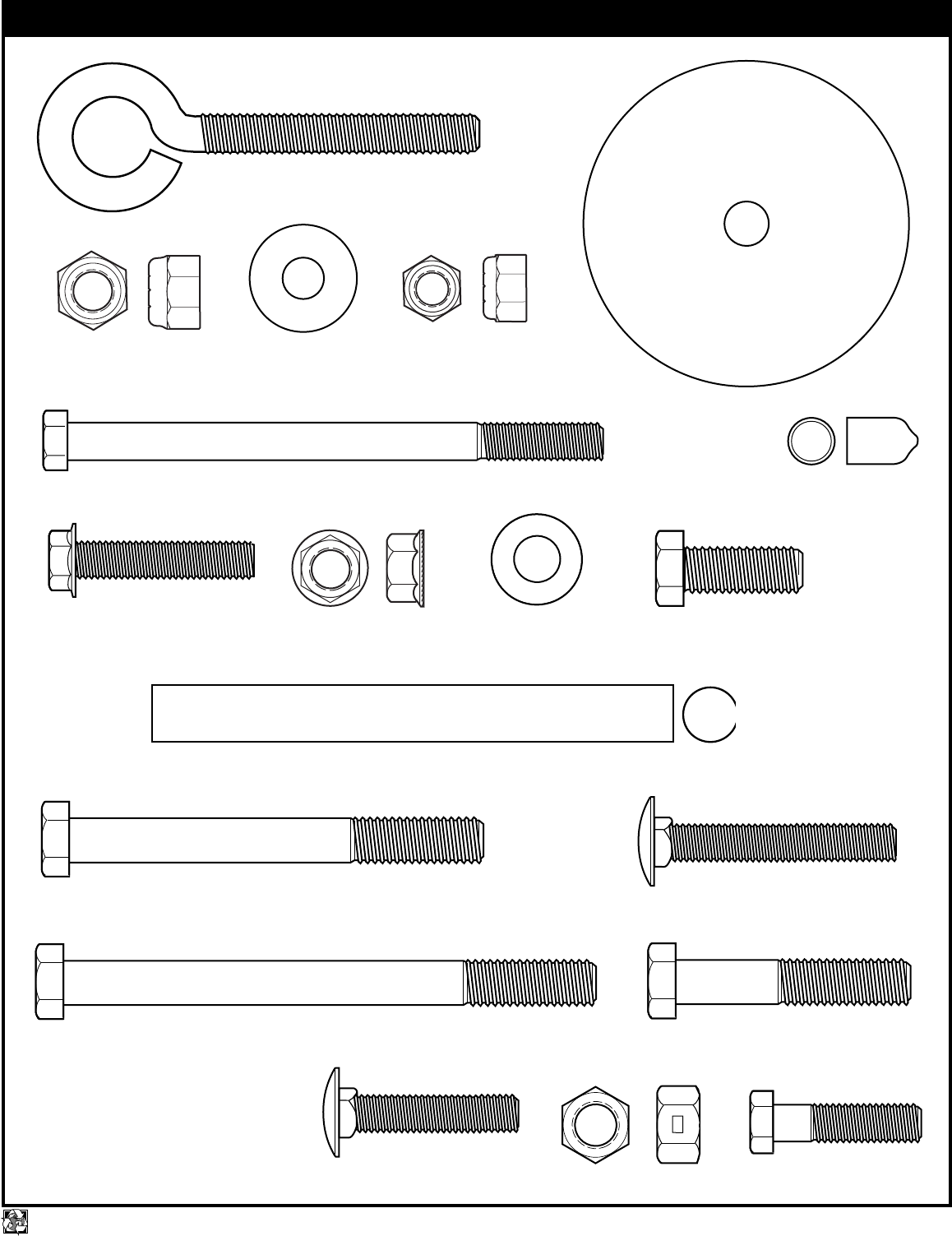
HARDWARE IDENTIFIER
Item #7 (1)
Item #20 (14)*
Item #11 (11)
Item #10 (1)
Item #39 (1)
Item #5 (1)
Item #15 (19)*
Item #35 (2)
Item #8 (6) Item #12 (1)
Item #13 (1)
Item #14 (2)
Item #16 (3)
Item #21 (1)
Item #23 (1)
Item #26 (4)
Item #36 (1)
Item #37 (3)
Item #19 (1)
4
P/N 211260A 10/01 printed on recycled paper
*You may have extra parts with this model.
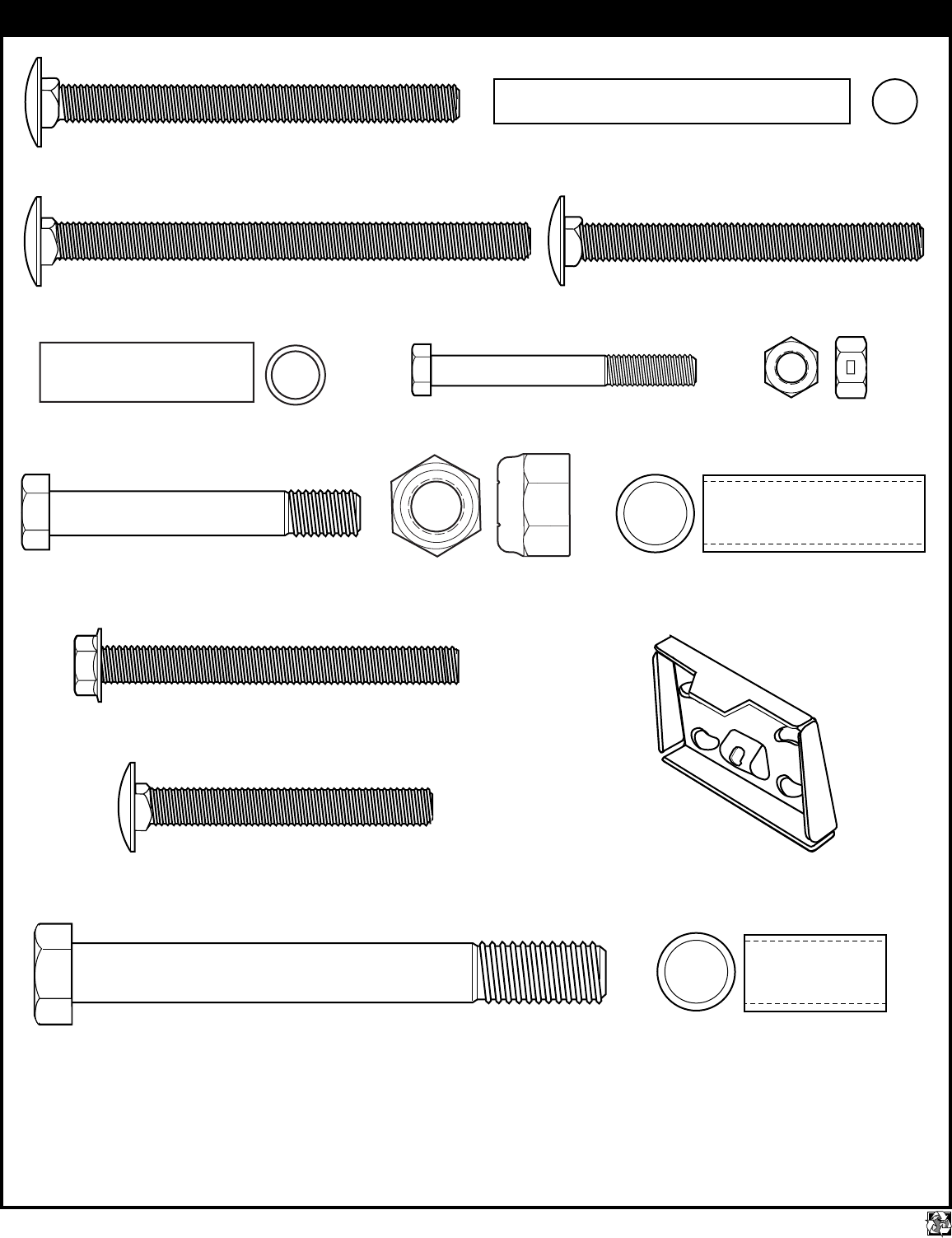
HARDWARE IDENTIFIER (continued)
Item #43 (2)
Item #42 (4)
Item #53 (1) Item #55 (1)
Item #58 (7)
Item #51 (2)
Item #50 (1)
Item #67 (8)
Item #65 (1)
Item #46 (2)
Item #54 (1) Item #59 (4)
Item #60 (4)
Item #62 (2)
#61 (1)
10/01 P/N 211260A
5
printed on recycled paper
HARDWARE IDENTIFIER (continued)
#74 (1)
#73 (1)
#72 (1)
#71 (1)
Item #75 (4)
#69 (1)
6
P/N 211260A 10/01 printed on recycled paper
WARNING: IF YOUR SYSTEM IS EQUIPPED WITH AN ACRYLIC
BACKBOARD, EXAMINE BACKBOARD FOR ANY DAMAGE THAT MAY
HAVE OCCURRED DURING SHIPMENT. CRACKS IN THE BACKBOARD
COULD RESULT IN SUDDEN BREAKAGE. IF BACKBOARD IS DAMAGED
IN ANY WAY PRIOR TO OR AFTER ASSEMBLY, CALL TOLL-FREE
NUMBER FOR FREE REPLACEMENT:
U.S. 1-800-558-5234; CANADA: 1-800-284-8339; http://www.huffysports.com
INSTRUCTIONS
IMPORTANT! WRITE MODEL NUMBER FROM BOX ONTO PAGE 1 OF THIS
OWNERS MANUAL
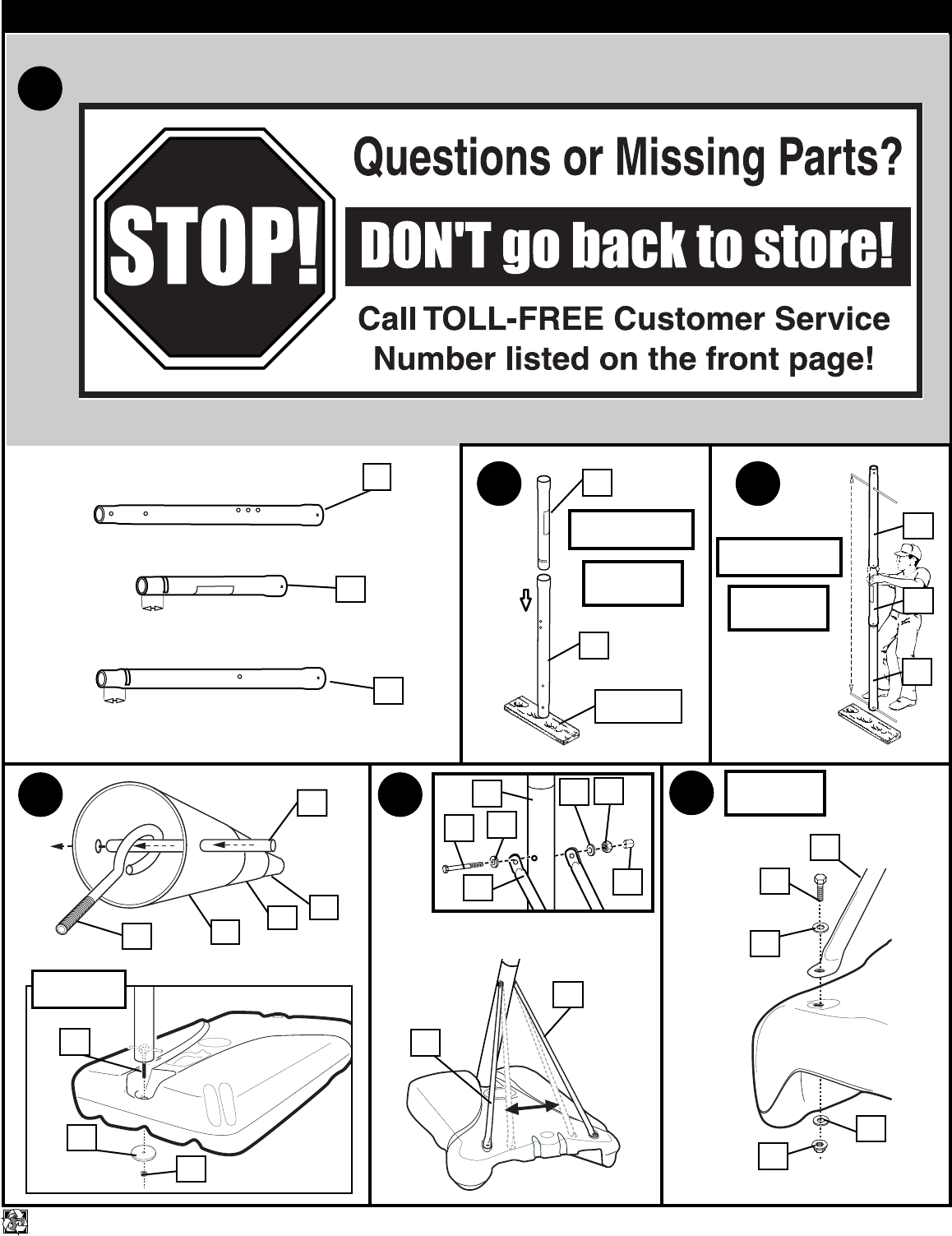
1. Mark pole sections with tape as shown.
2. IMPORTANT! Bounce pole top (1) and middle section (2) together as shown
until they no longer move toward taped reference mark. Upright assembly.
NOTE: Pole sections should have a 3-1/2" (9 cm) minimum overlap.
3. IMPORTANT! Holes in top (1) and bottom pole (3) sections MUST align to
correctly position elevator system toward playing surface. Add bottom pole
section (3) to assembly as shown and bounce until completely tight. NOTE: Pole
sections should have a 3-1/2" (9 cm) minimum overlap.
4. Install rod (4) through holes in bottom pole section (3) and eyebolt (5).
Insert pole assembly into tank assembly (6) as shown. Secure pole assembly with
disk (7) and lock nut (8).
NOTE: Two people recommended for this step.
5. Secure base struts (9) to pole using bolt (10) washers (11) and nut (12) as shown.
Rotate the non-secured ends of base struts (9) as shown.
6. Secure base struts (9) to base using bolt (14) washers (11) and nut (15).
7. Insert axle rod (16) through wheel (17), as shown. Secure wheel assembly to tank
(6) by tapping wheel downward with hammer, snapping it into position. Carefully,
turn tank (6) over.
8. Install upper pivot bracket (18) to front of base using bolt (19), washer (20) and nut
(8) as shown.
9. Insert bolt (21) through lower pivot bracket (22) as shown, bolt (21) will be secured
during step 12.
Carefully place base assembly on its side. Install lower pivot bracket (22) with bolt
(23), washers (20) and lock nut (8) as shown.
10. Secure both hinge tubes (22) to wheel bracket (25) with carriage bolts (26) and
flange nuts (15).
11. Install wheels (27) onto axle (28) and wheel bracket (25) with push caps (29) as
shown.
12. Position base as shown. Secure wheel bracket assembly with disc (30), washer
(20) and nut (8) as shown. NOTE: Two people recommended for this step.
13. Carefully reposition entire assembly as shown. IMPORTANT! Two people
recommended for this step.
14. Snap tinnerman nut (31) onto inner channel (32). Place inner channel into outer
channel (33) as shown.
15. Slide handle (34) into position as shown and secure with bolts (35), washers (35),
and nuts (15). Tighten completely.
16. Install bolt (36), washers (11), and nut (37) as shown. Tighten until washers (11)
are no longer loose. NOTE: Do not over tighten. Assemble trigger (22) to handle
assembly (34, 32, 33) as shown and secure with bolt (39) and washer (11). Tighten
completely.
17. WARNING: USE EYE PROTECTION WHEN INSTALLING SPRINGS.
Install trigger return spring (40) to handle assembly (32, 33) as shown.
18. Attach Accuheight label (41) to outer channel (33).
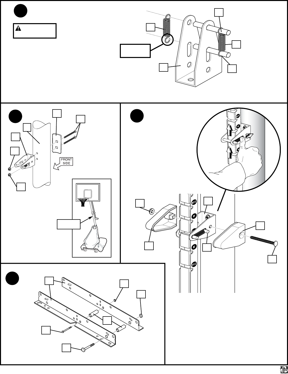
19. Attach spring (44) to pins (43) and install pins (43) onto pole mount bracket (45).
Attach other spring (44) to opposite side. NOTE: Gently enlarge eyelets of spring
with pliers if springs do not fit over pins.
WARNING: USE EYE PROTECTION WHEN INSTALLING SPRINGS.
20. Install pole mount assembly and reinforcement bracket (47) with carriage bolts (46)
to pole as shown. Tighten flange nuts (15) completely.
21. Push back sliding pin (43) as shown in Figure A to fit adjustable system assembly
through pole mount assembly. Then attach spring covers (48 & 49) onto pole mount
bracket (45) with bolt (50), and nut (15) as shown in Figure B.
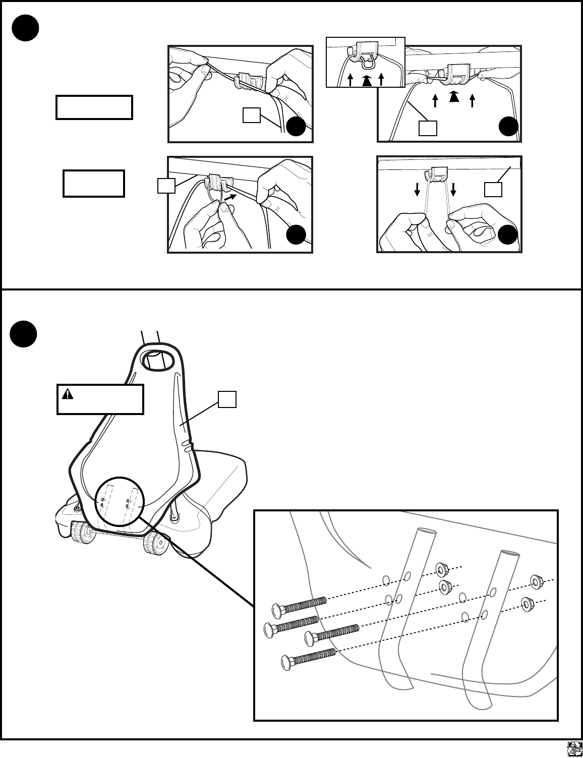
22. Install spacers (51) onto backboard brackets (52) with bolts (53, 54) and lock-nuts
(55, 37) as shown.
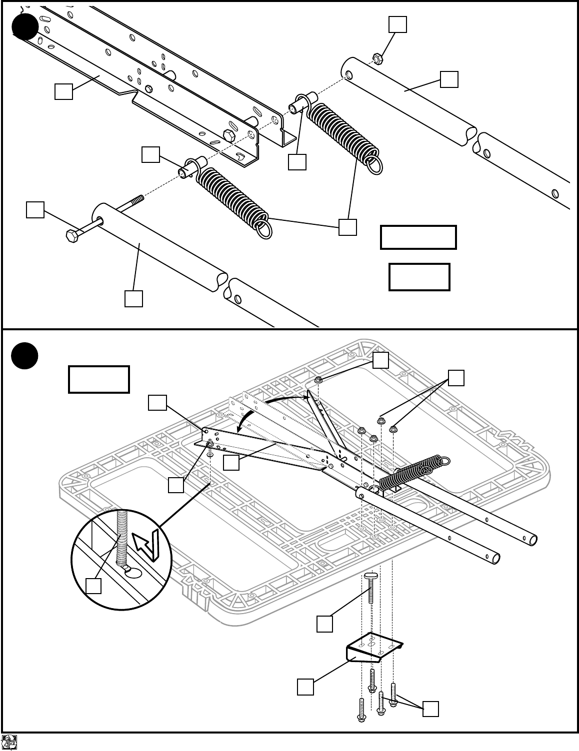
23. Assemble lower elevator tubes (56) as shown. NOTE : Tighten bolt (57) in lock nut
(58) until flush (even) with lock nut’s outer edge. IMPORTANT! It is necessary for
all parts to be installed for this mechanism to work safely and properly.
NOTE: Test fit bolts into holes of brackets (52) and carefully rock them in a circular
motion to ream out paint from holes if necessary
24. Bend brackets (52) to line up with holes in channel. Insert carriage bolts (62) into
hole as shown. Tighten completely.
Insert Tee-bolt (69) through Slam Jam Bracket (61) and attach to backboard with
nuts (15) and bolts (61) as shown.
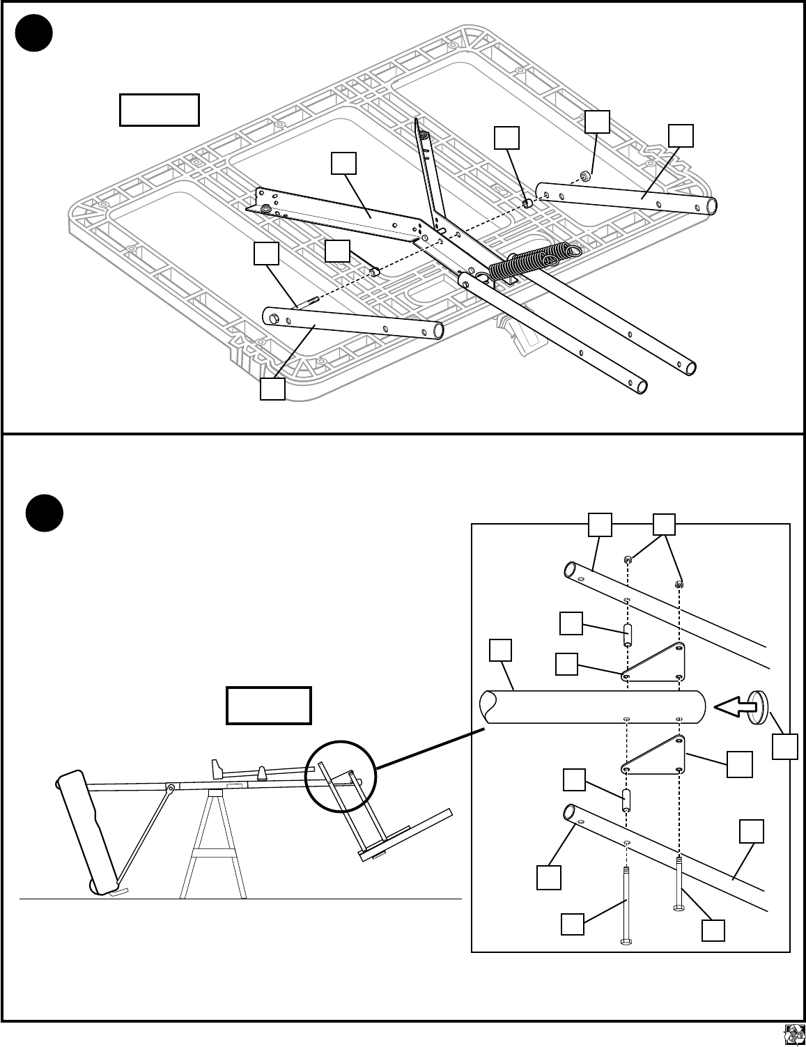
25. Assemble upper elevator tubes (63) to backboard brackets (52) as shown. NOTE:
Tighten bolt (57) in lock nut (58) until flush (even) with lock nut’s outer edge.
26. Support pole on sawhorse. Attach backboard assembly to top pole section (1) as
shown. Then install pole cap (64). NOTE: Two people are recommended for this
step. Use caution; elevator assembly is heavy.
27. Install upper elevator tubes (63) to triangle plates (66) as shown.
Install handle assembly to lower elevator tubes (56) using bolt (57), spacers (67),
and nut (58) as shown. NOTE: Tighten bolt (57) in lock nut (58) until flush (even)
with lock nut’s outer edge. NOTE: Before going on to next step, set adjustable
system assembly to the 10’ (3.05 m) setting.
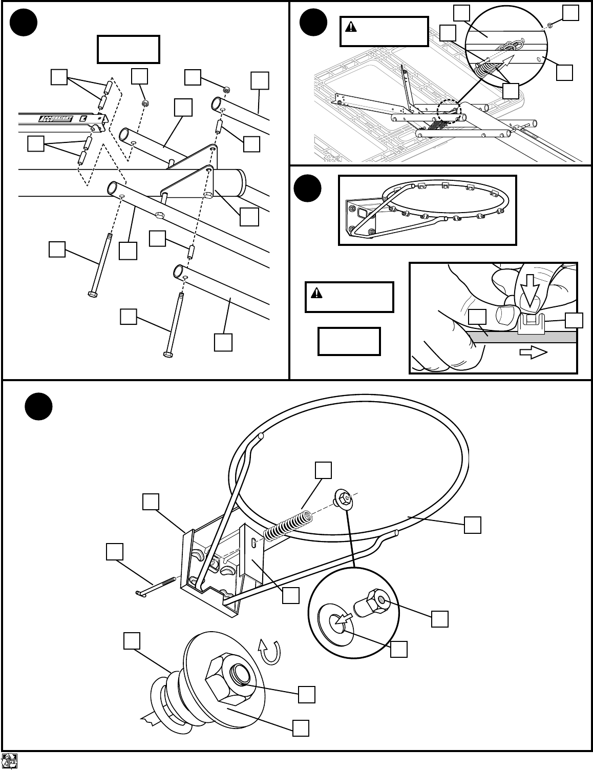
28. WARNING: USE EYE PROTECTION WHEN INSTALLING SPRINGS.
Insert bolt (57) through left side upper elevator tube (63), then stretch springs (68)
onto bolt (57). Insert bolt (57) through right side upper elevator tube (63) and
secure with nut (58).
29. Install net clips (81). The Quick Clip™ rapid release net system lets the net pull
away from the rim. This reduces the risk of player injury or property damage.
However, improper installation or a ball making contact at an odd angle may
disengage the net clip from the goal rim. Usually, the clip is reinstalled with little or
no problem. We hope that you agree this inconvenience is minor when compared
to the safety of the players. Quick Clip: US Patent No. 5,792,010/5,795,253
The two outer hooks on net clip must face towards inside of goal rim. Insert larger
hole in net clip onto rim stud, push down on net clip, then slide net clip right, locking
or snapping securely into position (clips must "snap" into place to insure a secure
fit).
NOTE: Net clips should not slide with ease. It is very important that the net clips
are in the locked position before going on to next step.
WARNING: USE OF THIS PRODUCT WITHOUT PROPER INSTALLATION OF
NET CLIPS, OR WHEN ALL NET CLIPS ARE NOT PRESENT COULD RESULT
IN BODILY HARM. BE SURE TO FOLLOW DIRECTIONS CAREFULLY.
30. Fit rim (70) into Slam Jam Bracket (61) and assemble Slam Jam Rim as shown.
WARNING: TWO PERSON MINIMUM REQUIRED FOR THIS PROCEDURE. NOT
FOLLOWING RECOMMENDATION MAY RESULT IN SERIOUS BODILY INJURY
AND/OR PROPERTY DAMAGE.
31. Install net (76).
IMPORTANT! Make sure net is held by all three hooks on the net clip.
A. Slide net into outer hook as shown.
B. Slide net into second outer hook creating a loop as shown. Push loop to back of
clip.
C. Pull loop up and through back of clip, snapping over the middle hook.
D. Pull net down to make sure it is held securely by all three hooks.
NOTE: If net releases during normal play, net was improperly installed. Please
review instructions to install net properly.
32. Attach front cover (82) to hinge tubes (24) using carriage bolt (42) and flange nuts
(15) as shown.
WARNING: DO NOT LEAVE ASSEMBLY UNATTENDED WHEN EMPTY, MAY
TIP OVER.
33. Apply height and moving label (77) to front of pole as shown.
34. Roll completed assembly to desired playing area. Secure assembly to ground using
rope (78) and tie down stake (79). Fill tank with 34 gallons of water. IMPORTANT!
Add two gallons (7.6 Liters) of non-toxic antifreeze in sub-freezing climates.
Add two gallons (7.6 liters) to tank to prevent freezing in sub-freezing climates.
Snap cap (80) into place.
WARNING: DO NOT ALLOW CHILDREN TO ADJUST HEIGHT.
35. Grasp handle and depress lever.
36. Push toward pole while holding lever. Raise or lower lever to desired height while
pushing forward on handle.
37. Release handle making sure that horizontal pin (43) is locked into slot.
10/01 P/N 211260A
7
printed on recycled paper
IMPORTANT! WRITE MODEL NUMBER FROM BOX ONTO PAGE 1 OF THIS OWNERS MANUAL
3.
5"
(13 cm)
MIDDLE
TOP
5"
(13 cm)
BOTTOM
1
3
2
1
2
2.
Note
(See Text Page)
IMPORTANT!
(See Text Page)
Wood Scrap
Note
(See Text Page)
IMPORTANT!
(See Text Page)
5
4
1
32
Note
(See Text Page)
2
3
1
4. 6.
5.
5
7
8
10 11
11 12
9
3
14
11
11
15
9
13
9
9
1.
Note
(See Text Page)

8
P/N 211260A 10/01 printed on recycled paper
8.
7.
16
17
8
20
18
19
18
23 20 22
21
20 8
26
25
15
24
11.
29
27 28
25
27
29
12.
21
30
20
8
9. 10.
Note
(See Text Page)
10/01 P/N 211260A
9
printed on recycled paper
13. ELEVATOR INSTALLATION (See steps 14-21)
32
33
32
31
14.
15.
11
15
11
15
34
35
35 34
39
31
11
32
37 11
36
11
11
39
38
34 Note
(See Text Page)
16.
17.
33
32
40
18.
33
41
IMPORTANT!
(See Text Page)
WARNING
(See Text Page)
10
P/N 211260A 10/01 printed on recycled paper
1
46
45
15
15
21.
50
49
45
15
48 43
Fig. B
22. 52
47
20.
FRONT
SIDE
51
53
54
55
37
19.
44
45
44
43
43
Note
(See Text Page)
WARNING
(See Text Page)
Fig. A
10/01 P/N 211260A
11
printed on recycled paper
23.
Note
(See Text Page)
IMPORTANT!
(See Text Page)
56
58
59
57
56
52
68
59
24.
15
52
62
15
15
69
61
60
62
Note
(See Text Page)
12
P/N 211260A 10/01 printed on recycled paper
58
64
166
56
67
65
56
56
66
57
67
Note
(See Text Page)
26.
58
57 59
59
52
63
25.
63
Note
(See Text Page)
10/01 P/N 211260A
13
printed on recycled paper
57
63
58
68
58
56
67
58
67
67 63
57 56
57
67
63
66
Note
(See Text Page)
27. 28.
29.
63
Note
(See Text Page)
30.
WARNING
(See Text Page)
WARNING
(See Text Page)
70
74
74
73
73
72
72
47
61
69
70 81
OUTSIDE VIEW
14
P/N 211260A 10/01 printed on recycled paper
82
32.
31.
Note
(See Text Page)
IMPORTANT!
(See Text Page)
WARNING
(See Text Page)
FRONT VIEW
76
BACK VIEW
76
70
A
B
C
D
70
10/01 P/N 211260A
15
printed on recycled paper
33.
43
ELEVATOR HEIGHT ADJUSTMENT
10 feet
(3.05m)
35. 36. 37.
77
78
78
80
79
34.
IMPORTANT!
(See Text Page)
WARNING
(See Text Page)
