Hughes Network Systems 24HX-001 point to multipoint - HUB User Manual EXB9
Hughes Network Systems point to multipoint - HUB EXB9
EXB9

11717 Exploration Lane, Germantown, MD 20876
Tel: (301) 428–5500 Fax: (301) 428–1868/2830
1027145–0001
Revision E
March 7, 2000
Hub Installation
and User Manual

1027145–0001 Revision Eii Hub installation
For important standards compliance information, see appendix B.
Copyright 1999–2000 Hughes Network Systems, a Hughes Electronics Corporation company
All rights reserved. This publication and its contents are proprietary to Hughes Network
Systems, a Hughes Electronics Corporation company. No part of this publication may be
reproduced in any form or by any means without the written permission of Hughes Network
Systems, 11717 Exploration Lane, Germantown, Maryland 20876.
Hughes Network Systems has made every effort to ensure the correctness and completeness
of the material in this document. Hughes Network Systems shall not be liable for errors
contained herein. The information in this document is subject to change without notice.
Hughes Network Systems makes no warranty of any kind with regard to this material,
including, but not limited to, the implied warranties of merchantability and fitness for a
particular purpose.
Trademarks
AIReach is a trademark of Hughes Network Systems. Other trademarks, marks, names, or
product names referenced in this publication are the property of their respective owners, and
Hughes Network Systems neither endorses nor otherwise sponsors any such products or
services referred to herein.

1027145–0001 Revision E iiiHub installation
Contents
About this manual vii. . . . . . . . . . . . . . . . . . . . . . . . . . . . . . . . . . . . . . . . . . . .
Important safety information ix. . . . . . . . . . . . . . . . . . . . . . . . . . . . . . . . . . .
1 Installation summary 1–1. . . . . . . . . . . . . . . . . . . . . . . . . . . . . . . . . . . .
1.1 Hub reference drawing 1–2. . . . . . . . . . . . . . . . . . . . . . . . . . . . . . . . . . .
1.2 Installation summary and checklist 1–3. . . . . . . . . . . . . . . . . . . . . . . . . .
2 Prerequisites 2–1. . . . . . . . . . . . . . . . . . . . . . . . . . . . . . . . . . . . . . . . . . .
2.1 Reviewing site data and plans 2–1. . . . . . . . . . . . . . . . . . . . . . . . . . . . . .
2.2 Planning ahead for building access 2–2. . . . . . . . . . . . . . . . . . . . . . . . . .
2.3 Tools needed for installation 2–3. . . . . . . . . . . . . . . . . . . . . . . . . . . . . . .
2.4 Specialized materials 2–6. . . . . . . . . . . . . . . . . . . . . . . . . . . . . . . . . . . . .
2.5 Prerequisites for commissioning 2–7. . . . . . . . . . . . . . . . . . . . . . . . . . . .
3 Installing mast mounts 3–1. . . . . . . . . . . . . . . . . . . . . . . . . . . . . . . . . .
3.1 Overview 3–2. . . . . . . . . . . . . . . . . . . . . . . . . . . . . . . . . . . . . . . . . . . . . .
3.2 Roof and ladder safety 3–3. . . . . . . . . . . . . . . . . . . . . . . . . . . . . . . . . . . .
3.3 Mount location 3–3. . . . . . . . . . . . . . . . . . . . . . . . . . . . . . . . . . . . . . . . .
3.4 Handling materials 3–4. . . . . . . . . . . . . . . . . . . . . . . . . . . . . . . . . . . . . .
3.5 Roof types 3–5. . . . . . . . . . . . . . . . . . . . . . . . . . . . . . . . . . . . . . . . . . . . .
3.6 Mast mount types 3–5. . . . . . . . . . . . . . . . . . . . . . . . . . . . . . . . . . . . . . .
3.7 Standard nonpenetrating mount 3–6. . . . . . . . . . . . . . . . . . . . . . . . . . . . .
3.8 Using existing structures as ODU mounts 3–13. . . . . . . . . . . . . . . . . . . .
4 Installing ODUs 4–1. . . . . . . . . . . . . . . . . . . . . . . . . . . . . . . . . . . . . . . .
4.1 Introduction 4–2. . . . . . . . . . . . . . . . . . . . . . . . . . . . . . . . . . . . . . . . . . . .
4.2 Transporting the ODU 4–5. . . . . . . . . . . . . . . . . . . . . . . . . . . . . . . . . . . .
4.3 Determining the HT alignment direction 4–6. . . . . . . . . . . . . . . . . . . . .
4.4 Preparing to install the antenna mount 4–10. . . . . . . . . . . . . . . . . . . . . . .
4.5 Installing the antenna mount 4–13. . . . . . . . . . . . . . . . . . . . . . . . . . . . . . .
4.6 Attaching the antenna to the mount 4–15. . . . . . . . . . . . . . . . . . . . . . . . . .
4.7 Adjusting the antenna azimuth 4–18. . . . . . . . . . . . . . . . . . . . . . . . . . . . .
4.8 Adjusting the antenna elevation 4–20. . . . . . . . . . . . . . . . . . . . . . . . . . . .
4.9 Making fine adjustments 4–22. . . . . . . . . . . . . . . . . . . . . . . . . . . . . . . . . .
4.10 Attaching the transceiver to the antenna 4–23. . . . . . . . . . . . . . . . . . . . . .
4.11 Grounding the ODU 4–25. . . . . . . . . . . . . . . . . . . . . . . . . . . . . . . . . . . . .
1027145–0001 Revision Eiv Hub installation
5 Installing IFL cables 5–1. . . . . . . . . . . . . . . . . . . . . . . . . . . . . . . . . . . .
5.1 IFL cable specifications 5–2. . . . . . . . . . . . . . . . . . . . . . . . . . . . . . . . . . .
5.2 Overview: IFL plan 5–3. . . . . . . . . . . . . . . . . . . . . . . . . . . . . . . . . . . . . .
5.3 Determining the IFL cable route 5–4. . . . . . . . . . . . . . . . . . . . . . . . . . . .
5.4 Penetrating the roof 5–5. . . . . . . . . . . . . . . . . . . . . . . . . . . . . . . . . . . . . .
5.5 Installing the penetration sleeve 5–6. . . . . . . . . . . . . . . . . . . . . . . . . . . .
5.6 Installing the IFL cable inside the building 5–7. . . . . . . . . . . . . . . . . . . .
5.7 Installing the hub lightning arrestor 5–8. . . . . . . . . . . . . . . . . . . . . . . . .
5.8 Installing the IFL cable on the roof 5–13. . . . . . . . . . . . . . . . . . . . . . . . . .
6 Installing indoor hub equipment 6–1. . . . . . . . . . . . . . . . . . . . . . . . . .
6.1 Installing the hub rack (optional) 6–2. . . . . . . . . . . . . . . . . . . . . . . . . . .
6.2 Installing IDUs 6–7. . . . . . . . . . . . . . . . . . . . . . . . . . . . . . . . . . . . . . . . .
6.3 Power supplies 6–11. . . . . . . . . . . . . . . . . . . . . . . . . . . . . . . . . . . . . . . . . .
6.4 Installing the CCM 6–26. . . . . . . . . . . . . . . . . . . . . . . . . . . . . . . . . . . . . .
6.5 SSIs 6–28. . . . . . . . . . . . . . . . . . . . . . . . . . . . . . . . . . . . . . . . . . . . . . . . . .
6.6 Connecting the IFL to the CCM 6–33. . . . . . . . . . . . . . . . . . . . . . . . . . . .
6.7 Redundancy bus cable 6–34. . . . . . . . . . . . . . . . . . . . . . . . . . . . . . . . . . . .
6.8 Front panel LCD operation 6–35. . . . . . . . . . . . . . . . . . . . . . . . . . . . . . . .
6.9 CCM power–on test 6–37. . . . . . . . . . . . . . . . . . . . . . . . . . . . . . . . . . . . . .
6.10 Hub LAN router and LAN hub 6–39. . . . . . . . . . . . . . . . . . . . . . . . . . . . .
7 Commissioning HTs 7–1. . . . . . . . . . . . . . . . . . . . . . . . . . . . . . . . . . . . .
7.1 Prerequisites for commissioning 7–2. . . . . . . . . . . . . . . . . . . . . . . . . . . .
7.2 HT commissioning procedure 7–3. . . . . . . . . . . . . . . . . . . . . . . . . . . . . .
7.3 Checking component status 7–7. . . . . . . . . . . . . . . . . . . . . . . . . . . . . . . .
7.4 HT to RT connection tests 7–11. . . . . . . . . . . . . . . . . . . . . . . . . . . . . . . . .
8 Final steps 8–1. . . . . . . . . . . . . . . . . . . . . . . . . . . . . . . . . . . . . . . . . . . . .
8.1 Weatherproofing 8–2. . . . . . . . . . . . . . . . . . . . . . . . . . . . . . . . . . . . . . . .
8.2 Inspection, cleanup, and sign–off 8–3. . . . . . . . . . . . . . . . . . . . . . . . . . .
8.3 Connecting customer equipment 8–3. . . . . . . . . . . . . . . . . . . . . . . . . . . .
9 Troubleshooting 9–1. . . . . . . . . . . . . . . . . . . . . . . . . . . . . . . . . . . . . . . .
9.1 Troubleshooting flow charts 9–1. . . . . . . . . . . . . . . . . . . . . . . . . . . . . . .
9.2 Additional troubleshooting information 9–6. . . . . . . . . . . . . . . . . . . . . .
9.3 Repair or replacement service 9–6. . . . . . . . . . . . . . . . . . . . . . . . . . . . . .
1027145–0001 Revision E vHub installation
10 Maintenance 10–1. . . . . . . . . . . . . . . . . . . . . . . . . . . . . . . . . . . . . . . . . . .
10.1 Adding or moving SSIs 10–2. . . . . . . . . . . . . . . . . . . . . . . . . . . . . . . . . . .
10.2 Replacing components 10–3. . . . . . . . . . . . . . . . . . . . . . . . . . . . . . . . . . .
10.3 Replacing the ODU 10–3. . . . . . . . . . . . . . . . . . . . . . . . . . . . . . . . . . . . . .
10.4 Replacing the IDU chassis 10–8. . . . . . . . . . . . . . . . . . . . . . . . . . . . . . . .
10.5 Replacing the CCM 10–10. . . . . . . . . . . . . . . . . . . . . . . . . . . . . . . . . . . . . .
10.6 Replacing SSIs 10–11. . . . . . . . . . . . . . . . . . . . . . . . . . . . . . . . . . . . . . . . .
10.7 Replacing the IFL 10–12. . . . . . . . . . . . . . . . . . . . . . . . . . . . . . . . . . . . . . .
10.8 Dismantling an HT 10–14. . . . . . . . . . . . . . . . . . . . . . . . . . . . . . . . . . . . . .
A Acronyms and abbreviations A- 1. . . . . . . . . . . . . . . . . . . . . . . . . . . . .
B Standards compliance B–1. . . . . . . . . . . . . . . . . . . . . . . . . . . . . . . . . . .
B.1 Outdoor unit B–2. . . . . . . . . . . . . . . . . . . . . . . . . . . . . . . . . . . . . . . . . . .
B.2 Indoor unit (ac) B–3. . . . . . . . . . . . . . . . . . . . . . . . . . . . . . . . . . . . . . . . .
C Terminating IFL cables C–1. . . . . . . . . . . . . . . . . . . . . . . . . . . . . . . . . .
C.1 Cable parts and terminology C–2. . . . . . . . . . . . . . . . . . . . . . . . . . . . . . .
C.2 Preparing the cable end C–3. . . . . . . . . . . . . . . . . . . . . . . . . . . . . . . . . . .
C.3 Attaching the connector C–6. . . . . . . . . . . . . . . . . . . . . . . . . . . . . . . . . . .
C.4 Applying heat–shrink tubing C–11. . . . . . . . . . . . . . . . . . . . . . . . . . . . . . .
Index . . . . . . . . . . . . . . . . . . . . . . . . . . . . . . . . . . . . . . . . . . . . follows appendix C
1027145–0001 Revision Evi Hub installation

1027145–0001 Revision E About this manual viiHub installation
About this manual
This manual provides instructions for installing and using
AIReachBroadband point–to–multipoint equipment at a hub
site.
This manual is intended for use by qualified equipment installers.
Installers must understand:
•Electronics fundamentals
•Cabling and connection practices
•Electrical circuits and grounding practices
•The importance of safety precautions
Installers must also be familiar with:
•Radio frequency (RF) fundamentals
•Applicable electrical, building, fire, and
safety codes and regulations
Note: HNS recommends a team of two installers to install the
AIReach Broadband indoor and outdoor equipment.
The instructions in this manual are organized according to tasks
and are intended to be followed in sequential order.
For site preparation instructions, see:
•Hub and Remote Terminal Site Preparation Guide,
document number 1027032–0001
For remote terminal installation instructions, see:
•Remote Terminal Installation and User Manual,
document number 1027144–0001
This manual primarily describes equipment manufactured and/or
provided by Hughes Network Systems (HNS), but in some cases
also refers to equipment that may be supplied by another vendor.
HNS equipment deliverables are defined in the customer
contract. Some equipment referred to in this manual may be
provided by the customer, as stated in the customer’s contract.
User qualifications
Organization
Related publications
HNS- and
customer-provided
equipment

1027145–0001 Revision E viii About this manual Hub installation
Revision record
Revision Date of issue Scope
AApril 21, 1999 Released for UL approval.
BJune 8, 1999 Added new and updated information.
CAugust 9, 1999 Added troubleshooting and maintenance
information.
DDecember 17, 1999 Updated illustrations; various revisions
and additions.
EMarch 7, 2000 Added overall installation checklist.
Added information for new antenna
mount design, and updated various other
information.
1027145–0001 Revision E Important safety information ixHub installation
Important safety information
For your own safety and protection, read this safety section
carefully. Keep this safety information where you can refer to it if
necessary.
This section introduces the types of warnings used in this manual
to alert you to possible safety hazards that could be encountered
while installing AIReach Broadband equipment.
DANGER
Fall hazard: Where you see this symbol
and DANGER heading, strictly follow the
warning instructions to avoid personal
injury or death from falling.
DANGER
Electric shock hazard: Where you see this
symbol and DANGER heading, strictly
follow the warning instructions to avoid
electric shock injury or death.
WARNING
Potential radio frequency (RF) hazard:
Where you see this alert symbol and
WARNING heading, strictly follow the
warning instructions to avoid injury to
eyes or other personal injury.
WARNING
Where you see this symbol and WARNING
heading, strictly follow the warning
instructions to avoid personal injury.
Types of warnings used
in this manual
1027145–0001 Revision E x Important safety information Hub installation
This manual includes the following safety warnings:
DANGER
If you have to walk on a roof or use a ladder
to access an installation site or equipment,
follow these precautions to prevent personal
injury or death:
•Do not walk near the edge of the roof.
•Watch out for overhead power lines.
Stay at least 6 meters (20 feet) from
power lines.
•Walk only on sound roof structures.
•Do not work on a roof or ladder in
high wind, rain, lightning, or other
adverse weather conditions.
•Follow all safety precautions from the
ladder or antenna manufacturer.
•Do not walk on a roof if a storm is
visible—even if the storm is distant.
Lightning can travel and strike in
advance of a storm.
WARNING
If you need to hoist materials to the
installation location, observe these
precautions to avoid personal injury:
•Use a rope strong enough to support
all of the materials that need to be
hoisted.
•Never stand under the rope while
materials are being hoisted.
•Hoist one concrete block at a time.
•Pass the rope through the center hole
of each concrete block. If you use the
hole on either end, the end can break
off, allowing the concrete block to fall.
•Be advised that the contents of the
mount kit can fall through the end of
the box if the box is tilted—especially
if the box has been damaged.
•Use a back brace.
Warnings appearing in
this manual
1027145–0001 Revision E Important safety information xiHub installation
WARNING
Potential radio frequency (RF) hazard:
•Keep away from the front of the
outdoor unit (ODU) antenna while the
ODU is operating. Note that you cannot
tell from outward appearance whether
the ODU is operating or not.
•Be careful with respect to the ODU you
are installing and ODUs that may
already be operating in the installation
area.
Failure to observe these warnings could
result in injury to eyes or other personal
injury.
WARNING
To help avoid death, injury, or damage from
a lightning strike, you must install a
lightning arrestor where the IFL enters the
building.
WARNING
The optional hub rack weighs approximately
115 pounds (52.2 kilograms) empty. Do not
attempt to lift it by yourself. Two people
should lift or move the rack, when necessary.
Failure to observe this warning could result
in personal injury.
The warning immediately below applies only to IDUs with
a dual ac or dc power supply:
WARNING
Multiple power connectors. Disconnect
both ac and dc power before servicing.
1027145–0001 Revision E xii Important safety information Hub installation
WARNING
To avoid the risk of electric shock,
remove power from the power circuit
before connecting power cables to the
IDU power supply.
WARNING
The IDU chassis must be solidly bonded to a
low–impedance ground (earth) source.
To avoid the risk of electric shock and/or
equipment damage, do not apply power to
the IDU chassis without a ground reference.
WARNING
To avoid the risk of electric shock, make
sure the dc power source breaker is off
before installing a remote power–off
circuit. Use a continuity tester to verify
that power is off.

HUB INSTALLATION
1027145–0001 Revision E Installation summary 1–1Hub installation
Chapter 1
Installation summary
This chapter includes:
•Hub reference drawing – page 1–2
•HT installation summary – page 1–3
The installation summary previews the entire installation process
and serves as a quick reference. For detailed information, see
chapters 2 through 8.
1027145–0001 Revision E 1–2 Installation summary Hub installation
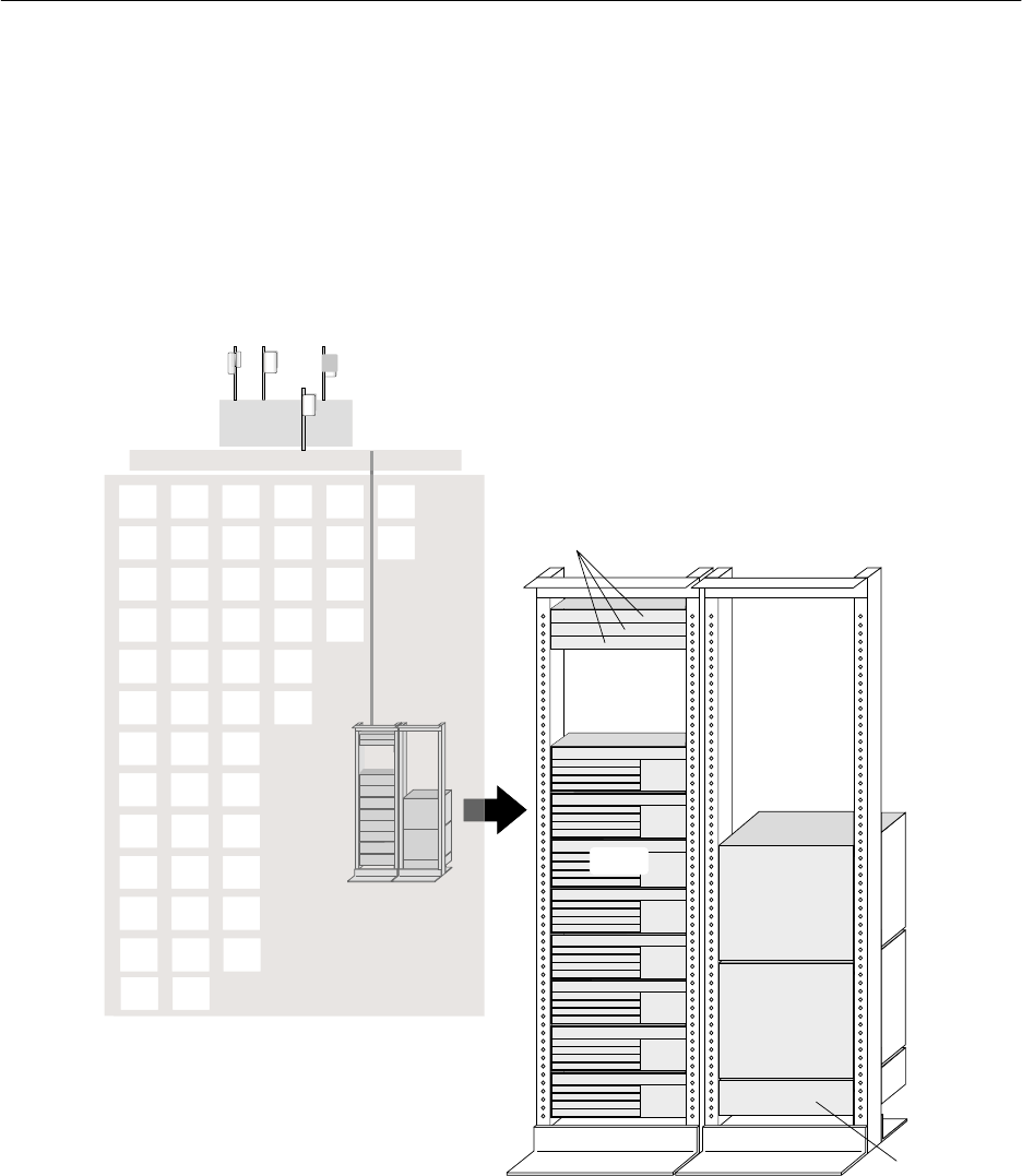
Figure 1-1 illustrates the main hub components:
•Outdoor units (ODUs)
•Intrafacility link (IFL)
•Indoor units (IDUs)
•Other indoor hub equipment
A hub terminal (HT) consists of an ODU and IDU connected by
an IFL. A hub includes at least one HT, but typically includes
multiple HTs.
IDUs
DC power distribution,
LAN hub, and
hub LAN router
T0006018
HT ODUs
Hub IDUs Transmission
equipment
Reference
timing source
ATM
multiplexer
TDM
multiplexer
Multiplexers are not provided by HNS unless
specified in the HNS-customer contract.
IFL
Hub site indoor
equipment
Figure 1-1 AIReach Broadband hub equipment
1.1
Hub reference
drawing

1027145–0001 Revision E Installation summary 1–3Hub installation
Components to be installed
The following AIReach Broadband components are installed at the
hub site:
•ODU(s) – Integrated antenna and transceiver
•IFL
•Indoor unit(s) (IDU), including:
- IDU channel and control module (CCM)
- IDU service–specific interfaces (SSIs)
•Optional: hub rack
Transmission equipment such as ATM and TDM multiplexers is
available from HNS as an option.
Summary of installation steps
Installation of HTs at a hub site consists of the following main
tasks:
Install the mast mount – page 3–6
Determine the HT alignment direction – page 4–6
Install antenna mount – page 4–13
Attach the antenna to the mount – page 4–15
Adjust the antenna azimuth – page 4–18
Adjust the antenna elevation – page 4–20
Attach the transceiver to the antenna – page 4–23
Ground the ODU – page 4–25
Determine the IFL cable route – page 5–4
Install the IFL cable (inside the building) – page 5–7
Install IFL lightning arrestor – page 5–8
Ground the lightning arrestor – page 5–12
Install the IFL cable (on the roof) – page 5–13
Test the IFL cable – page 5–15
1.2
Installation
summary and
checklist

1027145–0001 Revision E 1–4 Installation summary Hub installation
Connect the IFL cable to the ODU – page 5–15
Install the hub rack (optional) – page 6–2
Ground the rack – page 6–6
Install indoor unit (IDU) – page 6–7
Connect power supply – page 6–11
Ground the IDU chassis (if required) – page 6–14 (ac) or
6–17 (dc)
Install CCM – page 6–26
Install SSIs – page 6–28
Connect IFL to the CCM – page 6–33
For each IDU, repeat steps on pages 6–7 through 6–33.
Install CCM redundancy bus cable (if backup HT is present)
– page 6–34
Conduct CCM power–on test – page 6–37
Check component status – page 7–7
Verify prerequisites for commissioning – page 7–2
Perform commissioning steps – page 7–3
Test HT to RT connections (if possible) – page 7–11
Weatherproof connections – page 8–2
Obtain customer signoff – page 8–3
For detailed installation instructions, see chapters 2 through 8.
HUB INSTALLATION
1027145–0001 Revision E Prerequisites 2–1
Hub installation
Chapter 2
Prerequisites
This chapter discusses steps that are required prior to installation
of AIReach Broadbandhub equipment. It includes the following
sections:
•Reviewing site data and plans – page 2–1
•Planning ahead for building access – page 2–2
•Tools needed for installation – page 2–3
•Prerequisites for commissioning – page 2–7
Before you begin installing the equipment, review all previously
collected site data and site plans for information you will need to
install the indoor and outdoor equipment, including the IFL
(intrafacility link). For more information on the equipment to be
installed, see section 1.2.
Review:
•The completed Site Data Record from the Hub and Remote
Terminal Site Preparation Guide – The Site Data Record is
completed during and after the pre–installation site survey.
It includes the site address, hub terminal (HT) alignment for
each sector, IFL information, and much other information.
•Site drawings and photographs, including hub network
schematic and hub rooftop drawing – These should include
information about the site environment; existing equipment
and building features; equipment to be installed; location of
ODUs, IDUs, hub rack (if used), and the hub LAN router;
IFL routing; customer equipment to be connected to
AIReach Broadband equipment; equipment ID numbers;
and other information.
•Planning the ODU location, a section in the Hub and
Remote Terminal Site Preparation Guide – The ODU
location should already be selected; however, this section
contains information that is useful for the installer to know.
2.1
Reviewing site data
and plans

1027145–0001 Revision E
2–2 Prerequisites Hub installation
Before you go to the installation site, make sure you have all
necessary information (such as contact names and phone
numbers) for accessing all parts of the building you will need
to visit (roof, equipment rooms—which may be in the basement,
and other locations). This information should be available in the
Site Data Record, which is completed as part of the site survey.
Recommendations:
•Know who to contact for assistance (name, phone number,
working hours).
•Get good directions or a building map or floor plan, if
possible.
•You may need a key or pass code to gain access to the roof.
•Make all necessary arrangements for facility support and
building access before you go to the installation site.
2.2
Planning ahead for
building access

1027145–0001 Revision E Prerequisites 2–3
Hub installation
To install and commission AIReach Broadband hub equipment,
you need the tools listed in table 2-1 . You may need general–
purpose tools in addition to the specific tools listed here.
Table 2-1 Tools required for HT installation
(includes tools for IFL installation, antenna alignment, and initial testing)
√Item Purpose (or other comments)
Ladder May or may not be required; depends on building
Rope To hoist tools and equipment up ladders. Rope
must be long enough for ladders at the site. Must
be able to hold at least 35 pounds (16 kilograms).
This is the ODU weight. IFL cable is likely to
weigh more.
Snow shovel or
heavy–duty push broom To move roof gravel away from the ODU
installation site
1/2–inch drill Cordless drill preferred for work on roof. Drill with
power cord required for heavy–duty work (such
as mounting a rack to the floor).
Drill with bits for wood and
masonry. May be needed for IFL installation
Combination wrenches:
7/16 inch, 9/16 inch
10 millimeter, 13 millimeter
For installing the mast mount and antenna mount
Ratchet wrench with
9/16–inch socket For installing the mast mount
3/8–inch torque wrench with
13–millimeter deep socket Required for installing the antenna mount
5/32–inch (4–millimeter)
hex key wrench To loosen/tighten set screws in antenna bracket.
(Required if you need to change the bracket
orientation to left or right.)
No. 6 Phillips screwdriver Needed to attach IDU chassis mounting ears if
IDU chassis is rack mounted
1000° heat gun For applying shrink wrap tubing to protect cable
terminations
Cable cutters
2.3
Tools needed for
installation

1027145–0001 Revision E
2–4 Prerequisites Hub installation
Table 2-1 Tools required for HT installation – Cont’d.
(includes tools for IFL installation, antenna alignment, and initial testing)
√Purpose (or other comments)Item
Diagonal cutters (wire cutters)
Flush mount cutters
Excelta CX–1–78–1 cable
stripping tool Manufacturer: Excelta Corp., Buellton, CA
Crimp tool for #2 and #6
AWG ground lugs Manufacturer: Thomas & Betts, Memphis, TN
HCT–231 crimp tool For terminating N–type connectors
Channel locks
Soft jaw pliers Grip tool with soft surface, for gripping and
turning N–type connectors
Band cutters To remove shipping bands from mast mount
pieces
Carpenter’s knife
Splicer’s knife To terminate cables
Flashlight Primarily for IFL installation
100–foot tape measure
(metric equivalent: 30.5 meters) For measuring cable runs
Large backpack or
padded bag To haul ODU transceiver and antenna to the roof
Detailed local map Used to align HT antennas. Must show true
north, streets, buildings, and landmarks. Helpful if
the map shows magnetic declination (or
magnetic north versus true north). A U.S.
Geological Survey map is recommended. A
travel map will suffice if it shows sufficient detail.
Ruler or straight edge For antenna alignment; used to mark directions
on map
Pencil or broad–tip pen For antenna alignment; used to add markings to
local map

1027145–0001 Revision E Prerequisites 2–5
Hub installation
Table 2-1 Tools required for HT installation – Cont’d.
(includes tools for IFL installation, antenna alignment, and initial testing)
√Purpose (or other comments)Item
Protractor Used to align antenna. Must show 0° increments
from 0° to 180°.
Compass Used as an aid in aligning the antenna. Must be
accurate to within ±1°
Chalk or other marker For antenna alignment; to mark lines on the roof
Optional: Chalked plumb line
(the type you snap to
leave a straight chalk line)
For antenna alignment; to mark lines on the roof
Inclinometer Used to set antenna elevation
Personnel safety lines For safety on roof
Back brace To protect against back injury while hoisting or
lifting equipment and installation materials
Test set(s)
(DS1, DS3, or both) For commissioning tests. Test set type(s) needed
depends on services the hub supports (DS1,
DS3, or both).
Note: Vendor names, model numbers, and part numbers identify equipment known to
be suitable. Other comparable equipment may also be suitable.

1027145–0001 Revision E
2–6 Prerequisites Hub installation
To install AIReach Broadband HT equipment, you will need the
materials listed in table 2-2 . This is a list of key, mostly
specialized materials. It is not a comprehensive list. In addition to
the listed materials, installers should carry materials that are
commonly required to install outdoor telecommunications
equipment.
Table 2-2 Specialized materials required for RT installation
√Item Purpose (or other comments)
IFL cable For specifications, see page 5–2.
Ground cable IDU, ac (if not grounded through the power
cable): No. 16 AWG, green
IDU, dc: No. 14 AWG, green
ODU and lightning arrestor: No. 6 AWG or
greater, green
For rack installations (rack to ground bar): No. 2
AWG, green, stranded, and shielded
N type connectors N connectors, for IFL cable, see page 5–3.
Concrete blocks Used to anchor mast mount. For details, see
section 3.7 on page 3–6.
Weatherproofing compound Used to seal outdoor IFL connections. See
section 8.1 on page 8–2.
Outdoor waterproof tape Used to seal outdoor IFL connections. See
section 8.1 on page 8–2.
2.4
Specialized
materials

1027145–0001 Revision E Prerequisites 2–7
Hub installation
You will not be able to commission HTs (as detailed in chapter 7)
unless the Element Management System (EMS) is operational.
Specific requirements for commissioning are:
The EMS hardware and software must be installed and
operational.
The EMS database must be loaded and operational.
The EMS operator has to enter the hub MAC address
into the EMS database.
Additional prerequisites for commissioning are listed in chapter 7.
The additional prerequisites are satisfied when the HT is properly
installed. The prerequisites listed above must be accomplished
prior to HT installation—or commissioning will be delayed
until they are accomplished.
2.5
Prerequisites for
commissioning

HUB INSTALLATION
1027145–0001 Revision E Installing mast mounts 3–1
Hub installation
Chapter 3
Installing mast mounts
This chapter includes:
•Overview – page 3–2
•Roof and ladder safety – page 3–3
•Mount location – page 3–3
•Handling materials – page 3–4
•Roof types – page 3–5
•Mast mount types – page 3–5
•Standard nonpenetrating mount – page 3–6
•Existing structures – page 3–13
1027145–0001 Revision E 3–2 Installing mast mounts Hub installation
Typically, the installers assemble a nonpenetrating roof mount for
each ODU to be installed. In some cases, a different type of mast
mount may be used, or an existing structure may be used.
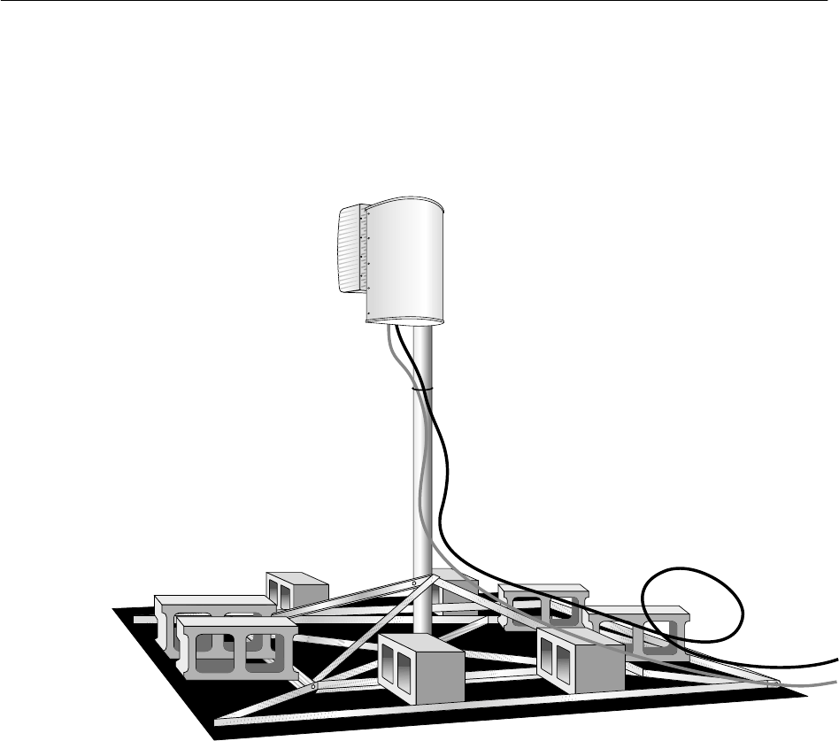
The mount supports the mast in a vertical position, and the ODU is
mounted on the mast, as shown in figure 3-1.
Figure 3-1 Mast mount supporting mast and ODU
T0006001
3.1
Overview
1027145–0001 Revision E Installing mast mounts 3–3
Hub installation
DANGER
If you have to walk on a roof or use a ladder
to access an installation site or equipment,
follow these precautions to prevent personal
injury or death:
•Do not walk near the edge of the roof.
•Watch out for overhead power lines.
Stay at least 6 meters (20 feet) from
power lines.
•Walk only on sound roof structures.
•Do not work on a roof or ladder in
high wind, rain, lightning, or other
adverse weather conditions.
•Follow all safety precautions from the
ladder or antenna manufacturer.
•Do not walk on a roof if a storm is
visible—even if the storm is distant.
Lightning can travel and strike in
advance of a storm.
Site preparation personnel specify the ODU location as part of
preparing the hub rooftop drawing.
1. Use the hub rooftop drawing to determine where to install
the mount (at the ODU location) and locate the IFL entry
point.
2. Make sure the roof penetration or entry point for the IFL is
suitable.
Important: The location(s) used for ODU installation must meet
the requirements listed in the Hub and Remote Terminal Site
Preparation Guide. Key considerations include:
•Line of sight
•IFL entry location
•Sources of interference
•Safety
•Ground point location
•Access
•Security
For details, see the Site Preparation Guide.
3.2
Roof and ladder
safety
3.3
Mount location
1027145–0001 Revision E 3–4 Installing mast mounts Hub installation
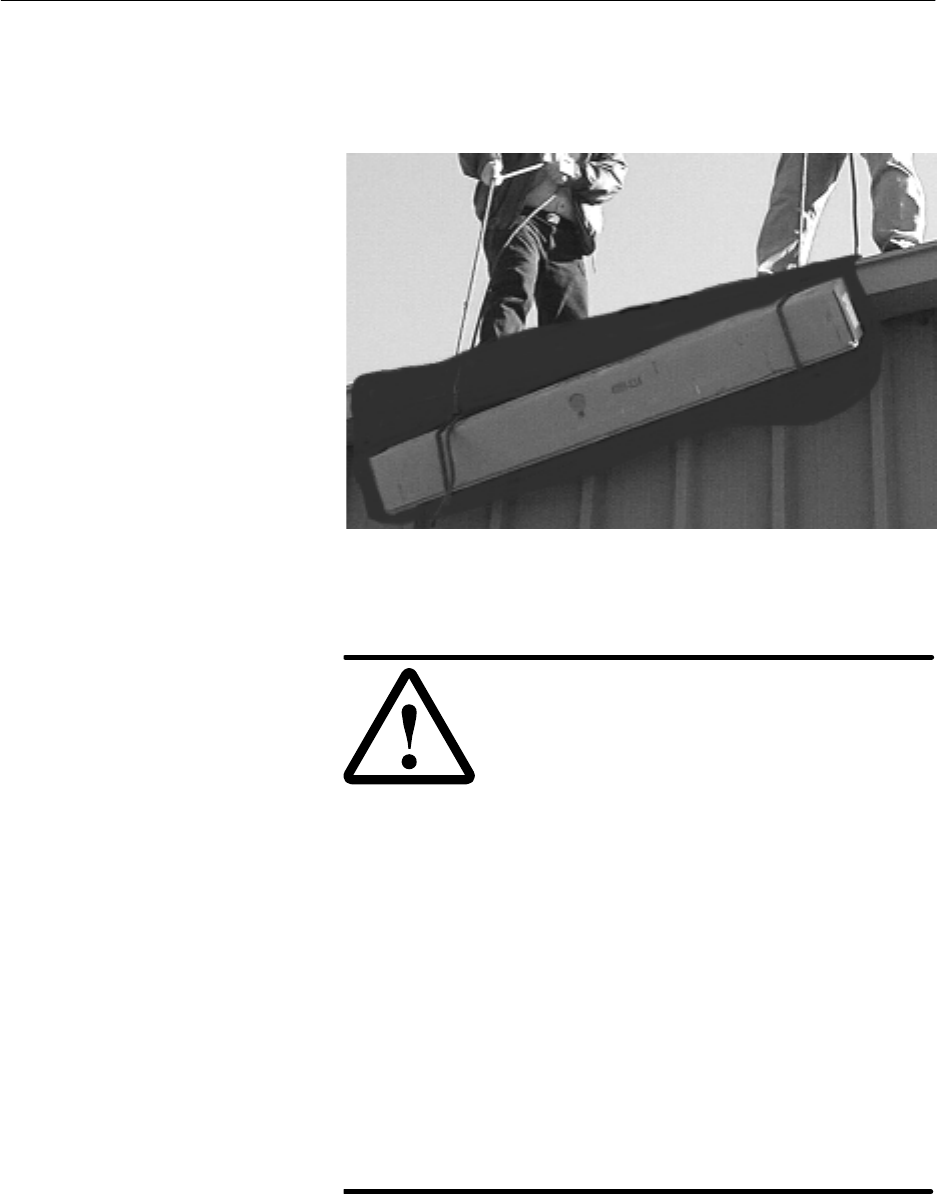
Depending on the installation location, you may have to hoist the
mount kit, ballast (concrete blocks), IFL cable, and tools to the
rooftop as shown in figure 3-2. Using two or more people for this
task will save considerable time.
T0006060
Figure 3-2 Hoisting materials to the installation location
WARNING
If you need to hoist materials to the
installation location, observe these
precautions to avoid personal injury:
•Use a rope strong enough to support
all of the materials that need to be
hoisted.
•Never stand under the rope while
materials are being hoisted.
•Hoist one concrete block at a time.
•Pass the rope through the center hole
of each concrete block. If you use the
hole on either end, the end can break
off, allowing the concrete block to fall.
•Be advised that the contents of the
mount kit can fall through the end of
the box if the box is tilted—especially
if the box has been damaged.
•Use a back brace.
If possible, avoid hoisting the ODU transceiver and antenna on a
rope. If possible, carry these components in a backpack or padded
bag.
3.4
Handling materials

1027145–0001 Revision E Installing mast mounts 3–5
Hub installation
Many roof types are suitable for AIReach Broadband ODU
installations. Mount installation procedures for the following
common roof types are described later in this chapter:
•Rubber cap sheet/glued rubber cap sheet
•Loose gravel on rubber cap sheet
•Corrugated metal
The roof type is a factor in the type of mast mount selected. Also,
some mount installation steps may be different, depending on the
roof type.
The following options are available for mounting a mast to
support the ODU:
•Nonpenetrating roof mount – This mount, essentially a
flat platform assembled from a kit, is suitable for most
applications. It can be used on various flat roof types. For
details, see section 3.7.
•Existing structure – An existing structure such as an
antenna tower can be used as a mast, or a mast can be
mounted to the structure, if the structure meets the
requirements given in the Hub and Remote Terminal Site
Preparation Guide.
3.5
Roof types
3.6
Mast mount types
1027145–0001 Revision E 3–6 Installing mast mounts Hub installation
The standard nonpenetrating roof mount, HNS 9200375–0001, is a
flat, metal–frame mount assembled from a kit. It requires a
6.5–by–6.5–foot space (1.98 by 1.98 meters) and includes a 7–foot
(2.1–meter) mast. You install the mount on a rubber pad; concrete
blocks are added for ballast.
The standard mount can be used on a variety of flat roof types, as
detailed below.
Instructions are given below for various types of roofs. See also
the manufacturer’s instructions, which are included in the mount
shipping carton.
Most flat roofs are topped with:
•Glued rubber cap sheet or
•Rubber cap sheet with gravel
Follow these instructions for either type of roof:
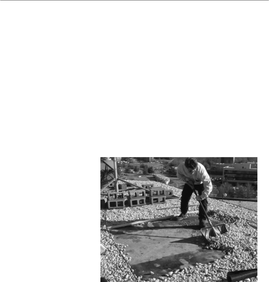
1. If the cap sheet is covered with gravel, use a push broom or
snow shovel to clear the gravel from the area where the
mount will be installed, as shown in figure 3-3.
T0006061
Figure 3-3 Clearing gravel from the installation location
2. Place the rubber pad on the roof surface where the mount
will be assembled.
3.7
Standard
nonpenetrating
mount
Flat roof – rubber sheet
(with or without gravel)
1027145–0001 Revision E Installing mast mounts 3–7
Hub installation
Figure 3-4 identifies the main mount components.
Outer
base angle
Diagonal
base angle
Inner
brace angle
Mast
Mast
brace angle
rt015
Rubber
pad
Figure 3-4 Mount components
•Follow steps 3 through 10 to assemble the mount.
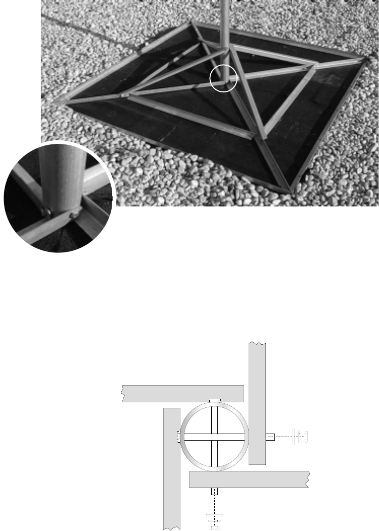
3. Place the mount’s four outer base angles on the rubber pad.
4. Place the mount’s diagonal base angles on the rubber pad
and connect them to the outer base angles at the locations
circled in figure 3-5.
Figure 3-5 Connecting diagonal base angles to outer base angles
Carriage bolt
1
1
1
1
2
2
2
2
Flat washer
Lock washer
Hex nut
rt013
1027145–0001 Revision E 3–8 Installing mast mounts Hub installation
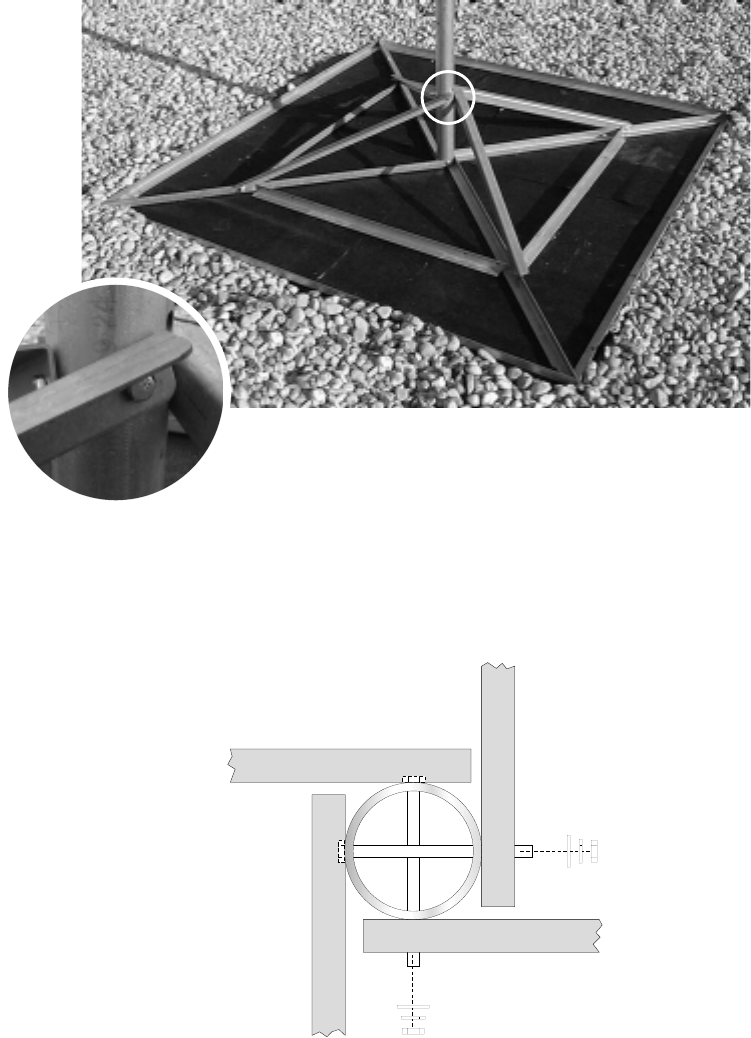
5. Place the mast between the diagonal base angles. Secure the
diagonal base angles to the mast as shown in figure 3-6.
1
1
1
1
2
2
2
2
Bolt
Flat washer
Lock washer
Hex nut
rt014
Figure 3-6 Attaching the diagonal base angles to the mast
Diagonal base angles opposite each other are secured to the
mast with one set of hardware as shown below.
rt042
1027145–0001 Revision E Installing mast mounts 3–9
Hub installation
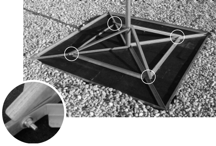
6. Attach the mast brace angles to the mast. See figure 3-7.
Figure 3-7 Attaching the mast brace angles to the mast
Carriage bolt
1
1
1
1
2
2
2
2
Flat washer
Lock washer
Hex nut
rt041
Mast brace angles opposite each other are secured to the
mast with one set of hardware as shown below.
rt042
1027145–0001 Revision E 3–10 Installing mast mounts Hub installation
7. Place the inner brace angles on the rubber pad and connect
them to the diagonal base angles and mast brace angles as
shown in figure 3-8.
Figure 3-8 Attaching inner brace angles to diagonal base
angles and mast brace angles
Carriage bolt
1
1
1
1
2
2
2
2
Flat washer
Lock washer
Hex nut
rt016
8. Refer to the Site Data Record (from the site survey) to
determine how many concrete blocks are required to anchor
the mount.
1027145–0001 Revision E Installing mast mounts 3–11
Hub installation
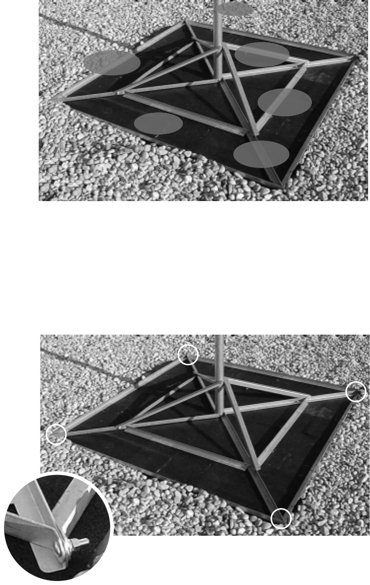
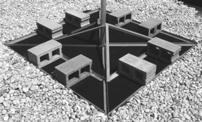
9. Place the concrete blocks on the mount so they are evenly
spaced, with the ends of each block anchoring both the
inner and outer base angles, as shown in figure 3-9.
Figure 3-9 Proper placement of concrete blocks on the mount
T0009060
10. When the mount installation is complete, if the roof is
covered with gravel, replace gravel up to the outside edges
of the mount. See figure 3-9.
Do not replace gravel in the area inside the mount base.
Leave the rubber pad exposed.
This section explains how to install the standard nonpenetrating
roof mount on a corrugated metal roof.
Special requirements:
•Pressure treated lumber, as specified in step 1 below,
and
•Twelve 1–inch–long (2.5–centimeter) lag bolts.
1. Obtain five pieces of pressure treated lumber, each 4 inches
by 4 inches by 8 feet long (10 centimeters by 10 centimeters
by 2.44 meters long).
2. Important: Select an area of the roof that is supported by a
metal I–beam to install the mount.
3. Cut the rubber pad into strips 4 inches wide by 8 feet long
(10 centimeters wide by 2.44 meters long).
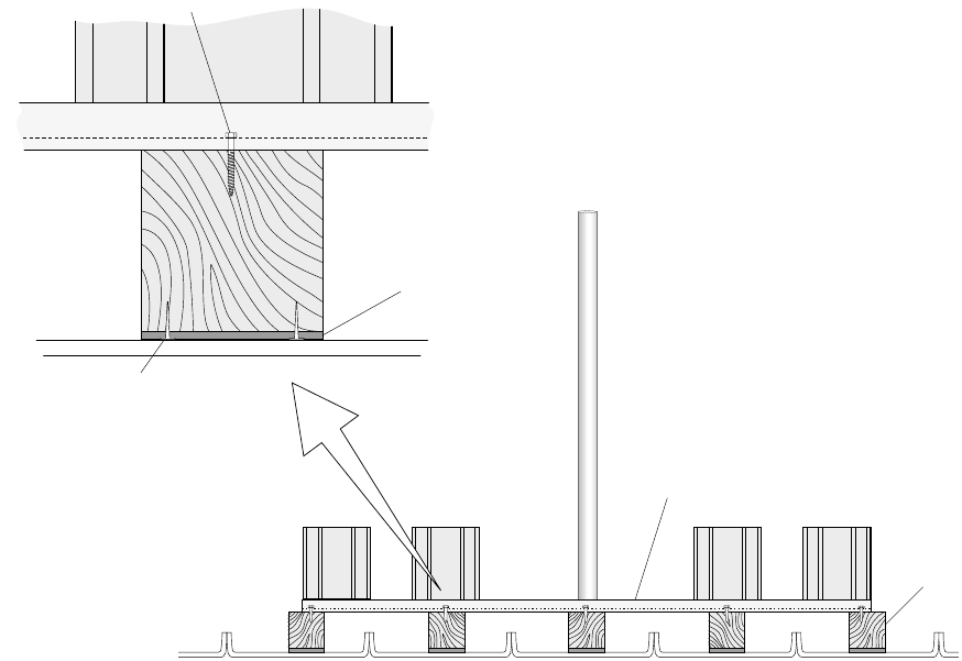
4. Use 5–penny shingle nails to nail one strip of rubber pad to
one surface of each piece of lumber. See figure 3-10.
Corrugated metal
1027145–0001 Revision E 3–12 Installing mast mounts Hub installation
5. Lay out the 4 x 4s, as shown in figure 3-10, so that each
piece is:
- In the recessed portion of the roof
- Parallel to the raised seams
- Equally spaced to support the mast, mount braces and
sides, and concrete blocks, as shown in figure 3-10.
Lay the lumber with the pad side down, so that the pad is
between the roof and the lumber.
Figure 3-10 Supporting the mount on a corrugated aluminum roof
Mast
Roof
Cinder block
(ballast)
Cinder
block
Roof
Detail
Rubber pad
(strip)
Wood
(4x4)
Wood
(4x4)
Mast mount
(assembled from kit)
Mast
mount
Lag bolt
hb008
Nail
End view
6. Follow steps 1 through 10 starting on page 3–6 to
assemble the mount.
Assemble the mount on the 4 x 4s so that when completed,
the mount is elevated above the aluminum roof.
7. Make sure the mount is evenly positioned on the 4 x 4s,
then use lag bolts to bolt the mount to the 4 x 4s.
Install the bolts through the holes in the mount’s outer
frame and into the wood. Use one bolt at each end of each
piece of lumber (as shown in figure 3-10). Use one bolt at
the center of each remaining side of the mount.
8. Add the required number of concrete blocks for ballast. See
steps 8 and 9 on page 3–10.

1027145–0001 Revision E Installing mast mounts 3–13
Hub installation
In some cases, you may be able to mount an ODU to an existing
structure, such as a tower built to support communications
antennas.
The key factors for determining if an existing structure can be
used as mast are that the structure must:
•Be securely attached to the building (and capable of
sustaining specified wind loadings).
•Have an outside diameter of 2.0 to 4.5 inches.
•Meet line of sight (LOS) requirements.
Important: In addition to these criteria, the structure must also
meet other requirements listed in the Hub and Remote Terminal
Site Preparation Guide.
3.8
Using existing
structures as ODU
mounts

HUB INSTALLATION
1027145–0001 Revision E Installing ODUs 4–1Hub installation
Chapter 4
Installing ODUs
This chapter explains how to install ODUs at the hub.
It includes:
•Introduction – page 4–2
•Transporting the ODU – page 4–5
•Determining the HT alignment direction – page 4–6
•Installing the antenna mount – page 4–13
•Attaching the antenna to the mount – page 4–15
•Adjusting the antenna azimuth – page 4–18
•Adjusting the antenna elevation – page 4–20
•Making fine adjustments – page 4–22
•Attaching the transceiver to the antenna – page 4–23
•Grounding the ODU – page 4–25
For ODU standards compliance information, see appendix B
(page B–2).
For ODU location requirements, see page 3–3.
1027145–0001 Revision E 4–2 Installing ODUs Hub installation
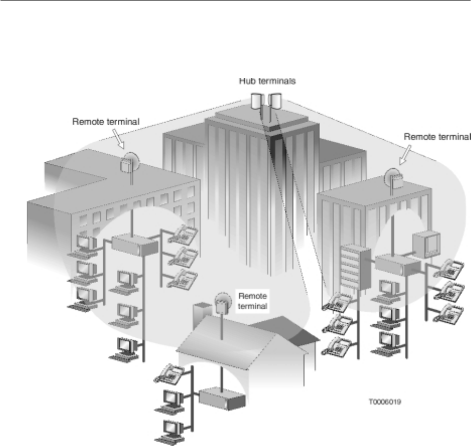
For conceptual reference figure 4-1 illustrates how hub terminal
(HT) ODUs communicate with remote terminals (RT) ODUs.
Typically, multiple HTs are used to provide multiple sectors and
achieve coverage up to 360°.
Figure 4-1 Hub ODUs communicating with RT ODUs
4.1
Introduction
1027145–0001 Revision E Installing ODUs 4–3Hub installation
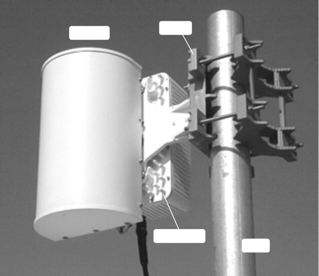
The HT outdoor unit (ODU) and integrated antenna attach to a
mount installed on a vertical mast, as shown in figure 4-2.
Figure 4-2 HT ODU
T0006063
Some antenna models are larger than the antenna shown here.
Transceiver Mast
Mount
Antenna
1027145–0001 Revision E 4–4 Installing ODUs Hub installation
When installing ODUs, observe the following safety warnings:
DANGER
Do not work on a ladder or roof without
first reading the safety warnings on page x
of this manual. Failure to observe these
warnings could result in personal injury or
death.
WARNING
Potential radio frequency (RF) hazard:
•Keep away from the front of the
outdoor unit (ODU) antenna while the
ODU is operating. Note that you cannot
tell from outward appearance whether
the ODU is operating or not.
•Be careful with respect to the ODU you
are installing and ODUs that may
already be operating in the installation
area.
Failure to observe these warnings could
result in injury to eyes or other personal
injury.
Safety warnings

1027145–0001 Revision E Installing ODUs 4–5Hub installation
Before you can install the outdoor equipment, the mast must be
installed.
The mast must have an outside diameter of 2.0 to 4.5 inches (5.0
to 11.4 centimeters) and must be securely mounted in a vertical or
horizontal position. If the mast is not installed, you will need to
install it before you proceed. For additional details concerning
the mast, see the AIReach Broadband Hub and Remote Terminal
Site Preparation Guide.
Before starting, make sure you have:
•Antenna mount
•Antenna
•Transceiver
•3/8–inch torque wrench with 13–millimeter deep socket
•5/32–inch (4–millimeter) hex key wrench
You will also need the following tools to plot HT alignments:
•Detailed local map – Must show true north, streets,
buildings, and landmarks. It is helpful if the map shows
magnetic declination, or magnetic north versus true north. A
U.S. Geological Survey map is recommended. A travel map
will suffice if it shows sufficient detail.
•Ruler or straight edge
•Protractor with markings from 0° to 180°.
•Pencil or broad–tip pen
•Compass
•Chalk or other marker to mark lines on the roof
•Optional: chalked plumb line (the type you snap to
leave a straight chalk line)
Unpack the ODU transceiver and antenna before going up to the
roof. Carry the transceiver and antenna to the roof (in separate
trips) in a backpack or padded bag. Make sure the transceiver or
antenna is secured in the backpack or bag.
Prerequisites
4.2
Transporting the
ODU

1027145–0001 Revision E 4–6 Installing ODUs Hub installation
To install and align the ODU, you must know the assigned HT
alignment direction and know where this direction is relative to the
HT location. Plot the planned sectors on a local map as explained
in this section—then you will know the alignment direction for
each HT to be installed.
1. Obtain the HT alignment direction for each HT to be
installed (for example, 45°, 135°, and so on) from the Site
Data Record (prepared by the site survey team).
2. Find true north on the map.
3. Find the hub site on the map, and clearly mark its location.
4. Carefully plot lines for true north (0°), south, east, and west,
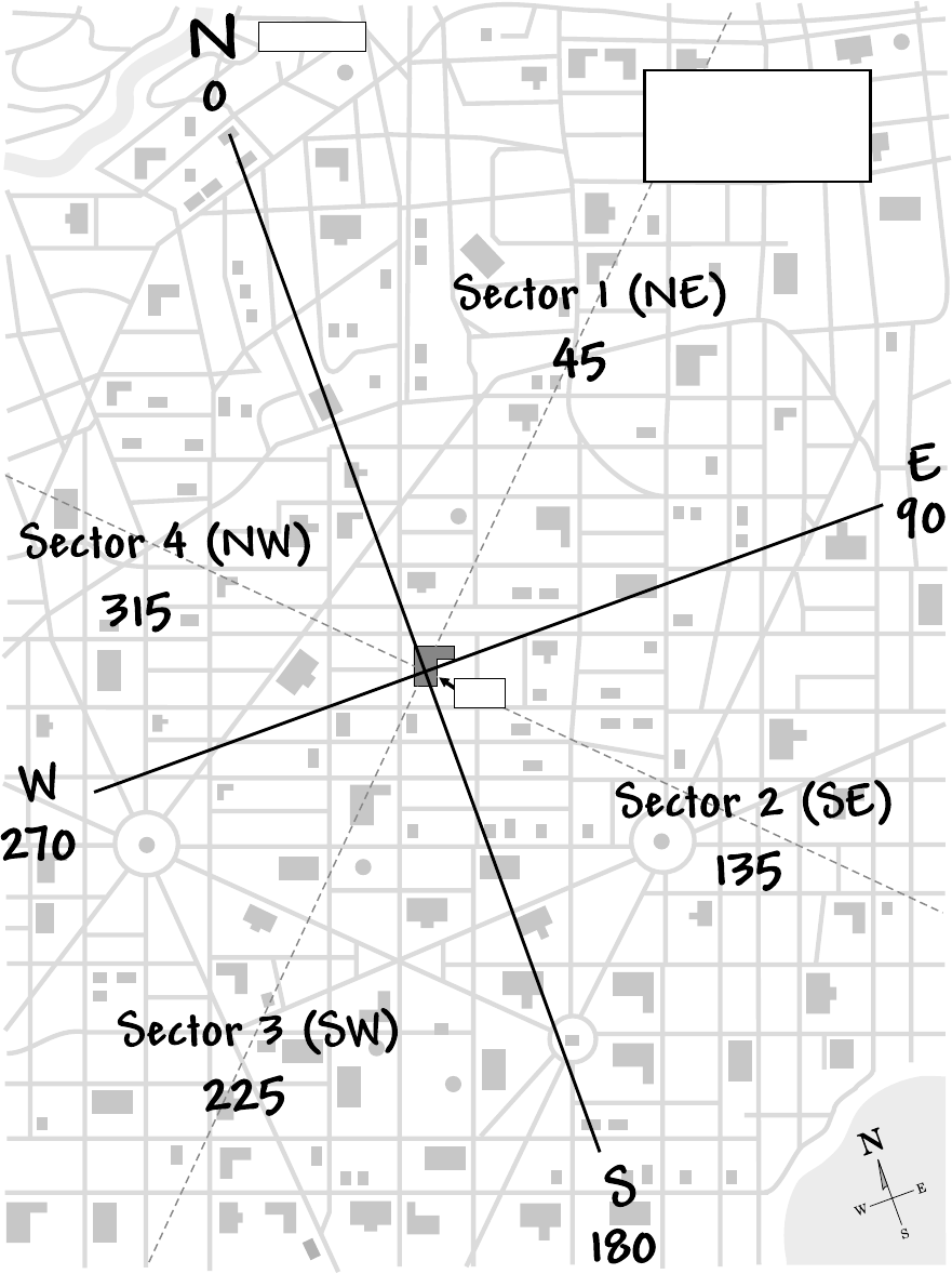
with the hub site at the intersection, as shown in figure 4-3
(page 4–7).
5. Plot the assigned alignment direction for each sector, and
identify the sectors, using figure 4-3 as an example.
Figure 4-3 shows four sectors for 90° ODUs. Sectors for
45° or 22.5° ODUs are 45° and 22.5° wide, respectively. In
some cases, a full 360° coverage range is not required.
6. On the roof, determine where true north is.
You may be able to determine true north using only the map
and landmarks.
If you use a compass to determine magnetic north, you
must adjust for magnetic declination (deviation from
true north) to determine true north. Some maps show
magnetic declination; some show magnetic north versus
true north.
If you are west of the north–to–south line where declination
is 0°, the declination is east (or positive). If you are east of
the 0° declination line, the declination is west (or negative).
To correct a magnetic compass reading to true north,
subtract east (positive) declination values from the
magnetic north reading. Add west (negative) declination
values. For example:
S If the declination is east, 14°, subtract 14° from the
magnetic reading.
S If the declination is west, –14°, add 14° to the
magnetic reading.
4.3
Determining the HT
alignment direction
1027145–0001 Revision E Installing ODUs 4–7Hub installation
Figure 4-3 Example: Sectors and HT alignment directions plotted on a local map
hb081
o
o
o
o
4 sectors plotted
for 4 90 ODUs°
HT alignment direction
o
o
o
o
True north
Hub
1027145–0001 Revision E 4–8 Installing ODUs Hub installation
Magnetic declination changes over time, so use only current
declination values.
A compass on a roof may be unreliable, due to metal
reinforcing rods in concrete and other metal. Stay away
from metal if possible. Take several readings. If readings
are not consistent, take readings on the street and mark true
north (accounting for declination) on the street where you
can see it from the roof. Use a compass only for
verification; do not rely on a compass alone to align the
antenna.
It may be helpful to mark true north, south, east, and west
on the roof using a chalked plumb line or some other
marking method.
Once you know true north (0°) you can easily determine
south, east, and west (at 90° intervals), as shown in figure
4-3. You can use the map, protractor, and landmarks to
determine any other direction (angle) on the map or with
respect to the actual site.
With true north, south, east, and west known, you can align
all HTs at the hub site. You could align them on the basis of
true north alone, but knowing the other three directions is
useful for reference and verification.
7. Use the map and landmarks to verify the directions you
have determined.
8. Place the protractor on the map, with its 0° (zero degree)
mark on true north. Then determine and plot the angle(s)
that corresponds to the HT alignment direction(s).
1027145–0001 Revision E Installing ODUs 4–9Hub installation
9. Using the map, directional markings you have made on the
roof, the protractor, and landmarks, point the center of the
antenna toward the HT alignment direction (i.e., toward the
center of the sector, or coverage area) as you install the
antenna. (See figure 4-4. Installation instructions for the
antenna are covered in sections 4.4 through 4.8.)
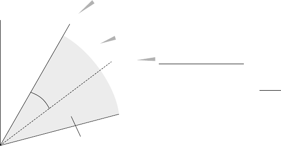
Each sector is defined by a sector angle and coverage angle,
as illustrated in figure 4-4. However, to align the antenna,
you only need to know the assigned HT alignment
direction.
Figure 4-4 HT sector definition and terminology
This example
shows a single
sector for
a 45 ODU.
°
hb082
Sector angle - Starting point for the
coverage angle, relative to 0° (north)
Coverage angle - Sector coverage (beamwidth)
HT alignment direction
+22.5
:
Sector angle 30.0
+ 1/2 coverage angle
= 52.5
°
°
°
52.5°
30°
True
north
0°
45°
Sector (shaded area)
ODU
22.5°
Keep the sector map and protractor handy. You will use
them as you physically install and align the antenna, as
explained in the following sections.
1027145–0001 Revision E 4–10 Installing ODUs Hub installation
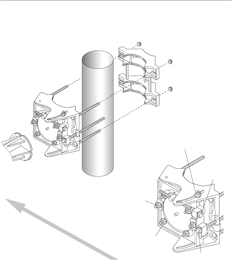
The antenna mount (HNS 1029056–0005) is shipped
fully assembled. Figure 4-5 shows an exploded view to show all
the parts. However, you do not need to take the mount apart to
install it, unless you need to reverse the mast clamp. (The mast
clamp is reversible, as explained later.)
Figure 4-5 Antenna mount
Antenna
bracket
Mast clamp
(rear part of antenna mount)
Mast interface
(front of
antenna
mount)
Mast
Mast interface - detail
Azimuth locking nuts
(2, top and bottom)
Elevation
locking nuts (2)
Antenna bracket
locking nuts (4)
Fine azimuth
adjuster
Fine
elevation
adjuster
Mast clamp nuts (4)
T0006056
HT alignment direction
(toward assigned sector)
The antenna mount design allows you to install and tighten the
mount and antenna and then adjust the antenna azimuth and
elevation without loosening the mount or antenna. Parts of the
mast interface move to allow these adjustments.
4.4
Preparing to install
the antenna mount

1027145–0001 Revision E Installing ODUs 4–11Hub installation
Important: To correctly install the antenna mount, read and
carefully follow all instructions in this section (4.4) through
section 4.8.
Prepare the mount for installation:
1. Turn the fine azimuth adjuster as necessary to position the
clevis (barrel) approximately in the middle of the threaded
part of the adjuster. See figure 4-6.
This step ensures that you will be able to adjust the adjuster
as necessary in either direction.
Do not turn the nut behind the block that holds the fine
azimuth adjuster.
T0009020
Fine azimuth
adjuster
Fine elevation
adjuster
Turn to
adjust. Do not
turn.
Clevis
Begin with clevis approximately
in the middle of the adjuster.
Figure 4-6 Fine azimuth and elevation adjusters
2. Turn the fine elevation adjuster as necessary to position the
clevis approximately in the middle of the threaded part of
the adjuster. See figure 4-6.
Do not turn the nut behind the block that holds the fine
elevation adjuster.
1027145–0001 Revision E 4–12 Installing ODUs Hub installation
Determine (approximately) how high on the mast to install the
mount:
1. Determine the approximate desired ODU/antenna
installation height.
Generally, the ODU height is determined as part of the RF
survey and is specified in the hub planning documents.
If the ODU height is not specified, install the HT ODU as
high as possible. The ODU/antenna must be high enough
to clear any obstructions.
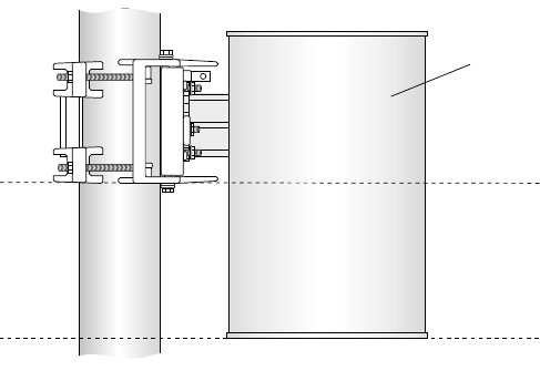
2. Refer to figure 4-7 for the mount position relative to the
position of the (not yet installed) antenna. As shown in
figure 4-7, when the antenna is installed (later), the antenna
vertical center is approximately at the same height as the
bottom of the mount.
Antenna
(front)
Antenna
center
vertical
The antenna and
mount are not
installed yet.
They are shown
here to indicate the
antenna height
relative to the
mount height.
T0006032
Antenna
bottom
Some antenna models may be
smaller than the antenna shown here.
Mast
Figure 4-7 Mount height relative to desired antenna height
ODU height
1027145–0001 Revision E Installing ODUs 4–13Hub installation
Follow the steps below to install the antenna mount.
1. Determine which side of the mast clamp to use:
T0009024
Mast clamp
Use this side against the mast if the
mast outside diameter is
.
less than
3.5 inches (8.9 centimeters)
Use this side against the mast if the
mast outside diameter is 3.5 inches
(8.9 centimeters) or larger.
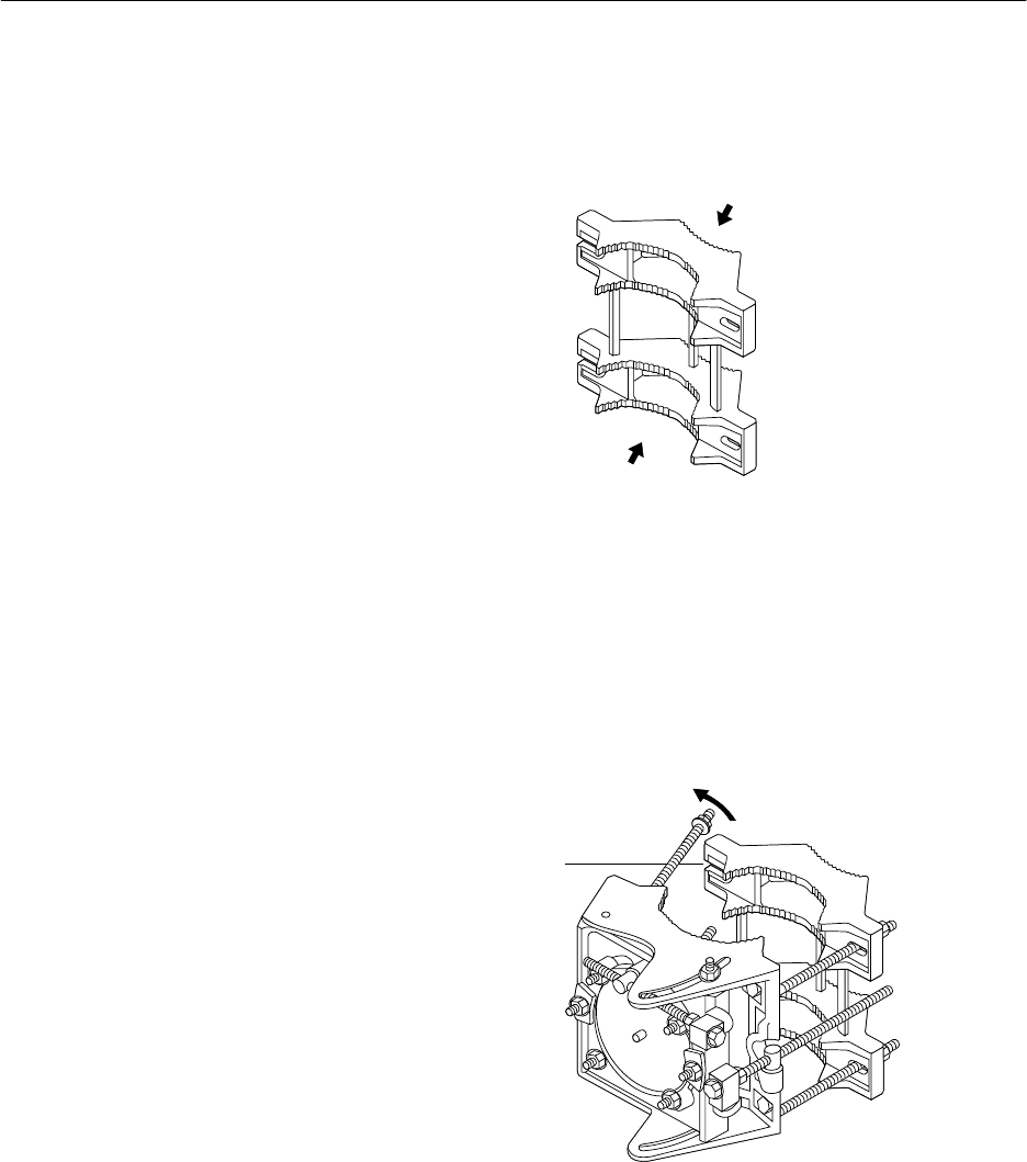
2. One side of the mast clamp has two open–end bolt holes
that allow the long bolts that are attached to the mast
interface to swing in or out. See figure 4-8. At the side of
the mount where the two open–end bolt holes are, swing the
two bolts outward so you can open the mount enough to
place it around the mast.
T0009032
Open-end
bolt hole
Figure 4-8 Opening the mount
4.5
Installing the
antenna mount
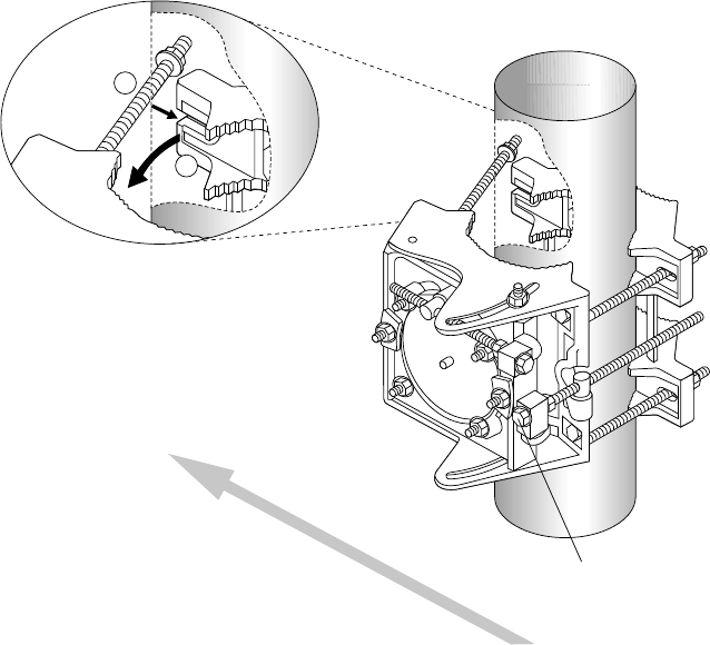
1027145–0001 Revision E 4–14 Installing ODUs Hub installation
3. Place the mount on the mast, as shown in figure 4-9.
The fine azimuth adjuster must be on the side of the
mount opposite the HT alignment direction, as
illustrated in figure 4-9. This allows you to make azimuth
and elevation adjustments from behind the antenna, so you
can stay out of the beam area.
To get the azimuth adjuster on the side opposite the HT
alignment direction, you may have to turn the entire mount
180°, depending on whether the ODU will be mounted to
the left or right of the mast.
(If you are facing the mast interface—as a reference—it
doesn’t matter whether the mount swings open to the right
or to the left, as long as the azimuth adjuster is opposite the
HT alignment direction.)
4. Swing the clamp toward the interface until you can
“capture” the clamp by swiveling the free–swinging bolts
into the two slots in the clamp, as shown in figure 4-9.
Figure 4-9 Installing the antenna mount
Mast
clamp
1. Swing clamp toward interface.
2. Swivel bolt into slot.
T0006054
1
2
HT alignment direction
(toward assigned sector)
Fine azimuth
adjuster
5. Finger tighten the four mast clamp nuts.
Tighten the nuts enough to hold the mount to the mast, but
leave them loose enough so you can smoothly pivot the
mast interface and mast clamp around the mast to permit
coarse azimuth adjustment.
(You fully tighten the mast clamp nuts later.)
1027145–0001 Revision E Installing ODUs 4–15Hub installation
Attach the antenna to the mount:
1. Make sure the antenna is right side up.
On the back of the antenna is a label with an arrow that
points to the top of the antenna. (The label reads “Install
antenna this side up.”)
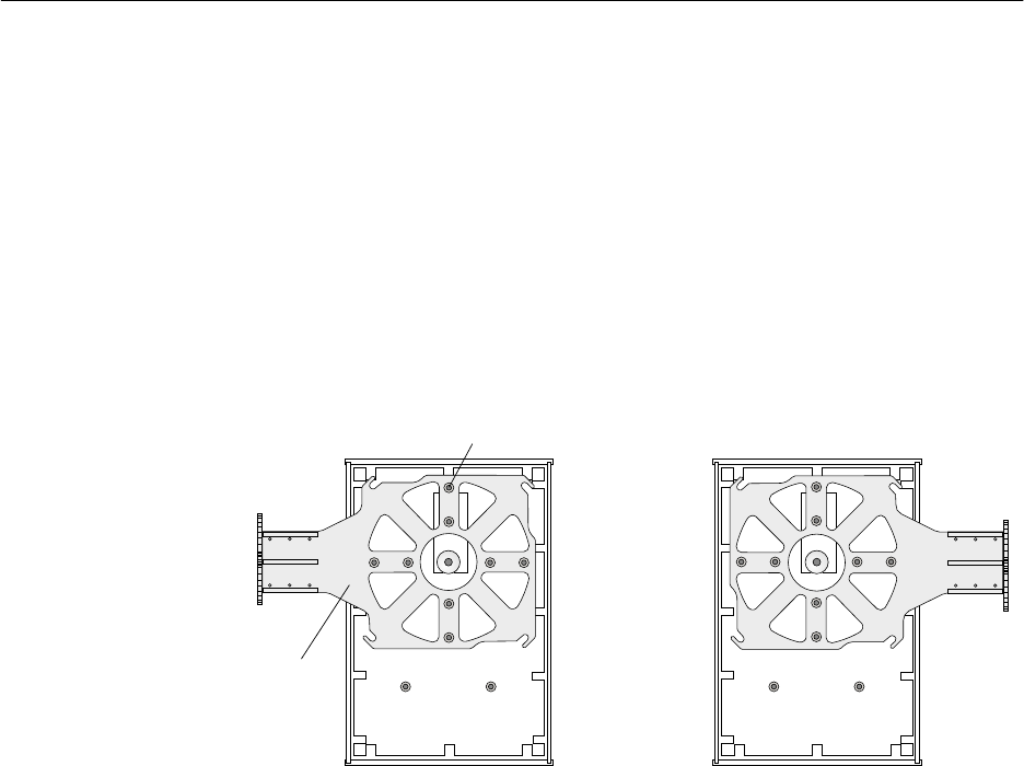
2. The antenna bracket can point to the left or right, as shown
in figure 4-10. Before attaching the antenna to the antenna
mount, make sure the bracket orientation (to the left or
right) is suitable for your installation location. If necessary,
you can use a 5/32–inch hex key wrench to remove the
eight set screws and reinstall the bracket so it points in the
opposite direction.
Figure 4-10 The antenna bracket can be oriented to
mount to the antenna mount on the left or right.
T0006010
Antenna
bracket
Antenna (rear view)
Set screws (8)
Some antenna models may be smaller
than the antenna shown here.
4.6
Attaching the
antenna to the
mount
1027145–0001 Revision E 4–16 Installing ODUs Hub installation
Attach the antenna to the mount as follows:
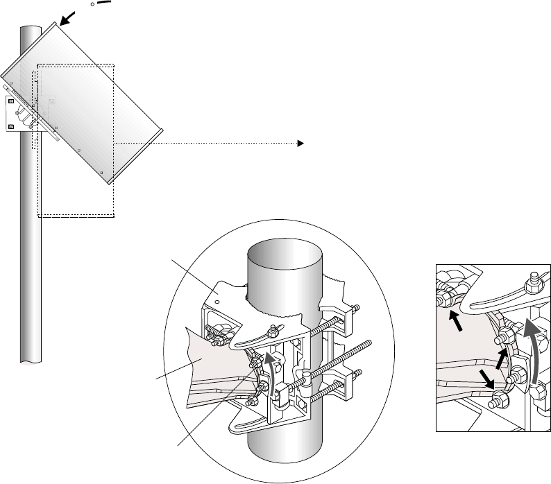
1. With the antenna radome facing in the direction of the
assigned HT sector, position the round, flat surface of the
antenna bracket approximately 1 inch (2.5 centimeters)
from the mast interface.
2. Rotate the antenna approximately 45° away from the HT
alignment direction (assigned sector) until the antenna
bracket reliefs (curved indentations) are aligned with the
four nuts on the mast interface, as shown in figure 4-11.
T0006033
45
Alignment direction
Antenna
Mast
interface
Antenna
bracket
Antenna bracket
locking nut (1 of 4)
Close-up view:
Antenna bracket reliefs (4)
Relief
Figure 4-11 Rotating the antenna so the antenna
bracket can be placed against the mast interface
3. Press the antenna against the mast interface.
Attaching the antenna
1027145–0001 Revision E Installing ODUs 4–17Hub installation
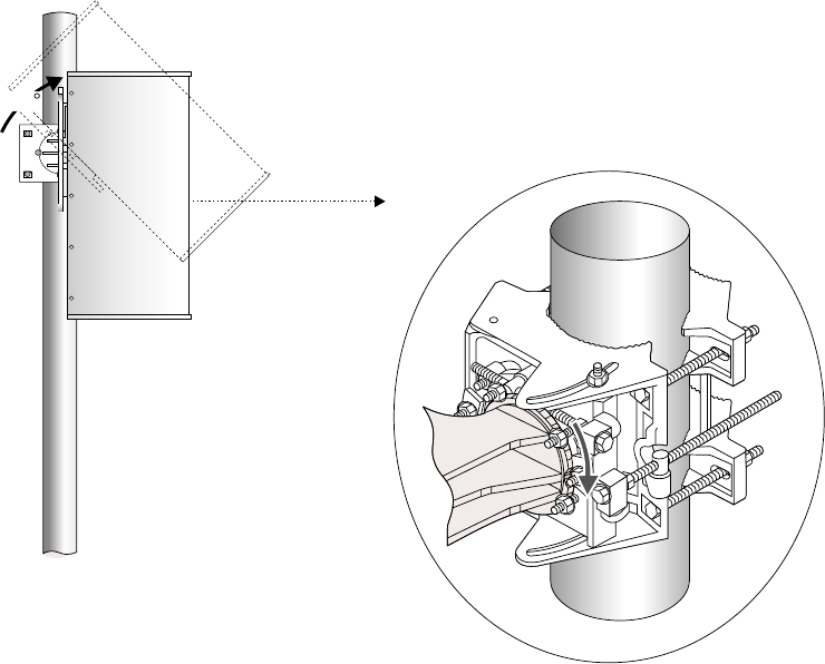
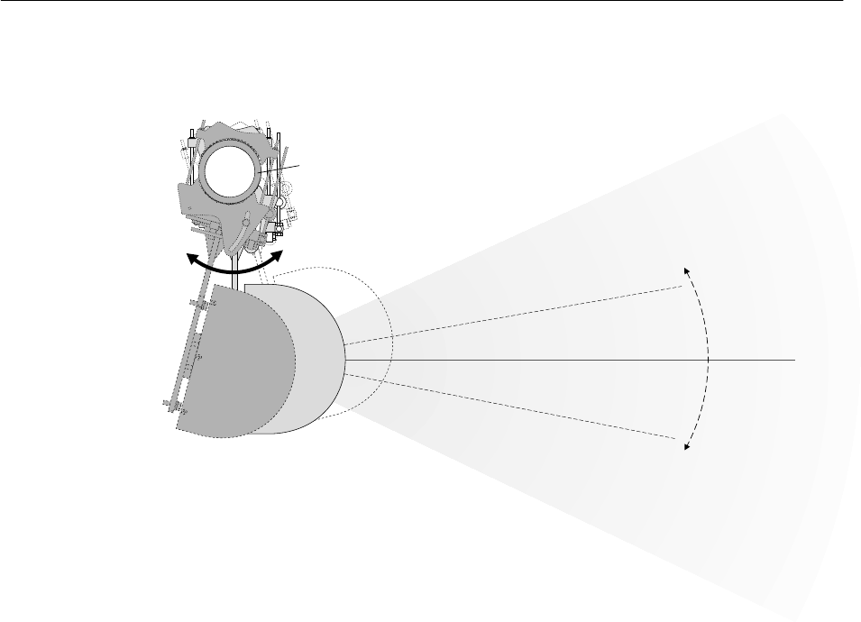
4. Rotate the antenna approximately 45° toward the HT
alignment direction (sector), to the upright position, as
shown in figure 4-12—then finger tighten the antenna
bracket locking nuts so the antenna is snug and without
excess movement.
The antenna is now “captured” by the antenna mount.
However, because the antenna bracket nuts are not fully
tightened, you can rotate the antenna to adjust its elevation.
T0006034
Antenna
45
Figure 4-12 Rotating the antenna to the
upright installation position
1027145–0001 Revision E 4–18 Installing ODUs Hub installation
To adjust the antenna azimuth (horizontal pointing direction), you
move the antenna to the left or right, as illustrated in figure 4-13,
until it is pointed in the desired direction (HT alignment direction).
Figure 4-13 Antenna azimuth adjustment (to right or left)
Sector
center
HT antenna
HT alignment direction
T0006048
Top view
Left
Right
adjusted
by 10 .°
+
_
Antenna
azimuth
can be
Mast
Adjust the antenna azimuth as follows:
1. Rotate the antenna mount (and antenna) around the mast to
the HT alignment direction.
To determine the HT alignment direction with respect to
your location on the roof, use the sector map you created
(section 4.3) and a compass and/or protractor. Landmarks
may also help.
4.7
Adjusting the
antenna azimuth
1027145–0001 Revision E Installing ODUs 4–19Hub installation
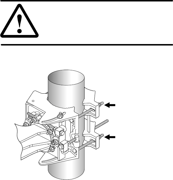
2. When the azimuth is properly adjusted, use a torque
wrench with a deep socket to tighten the four mast
clamp nuts to 16 foot–pounds torque (21.7 Newton–
meters). See figure 4-14. Tighten each bolt a little at a
time, moving from bolt to bolt in an X pattern.
CAUTION
Correct torque is essential for successful
installation and adjustment. Tighten nuts to
the exact torque stated. Incorrect torque
may result in damage to equipment.
Figure 4-14 Mast clamp nuts
T0006057
Mast clamp nuts
(Only 2 of the 4 nuts
are visible in this
illustration.)
1027145–0001 Revision E 4–20 Installing ODUs Hub installation
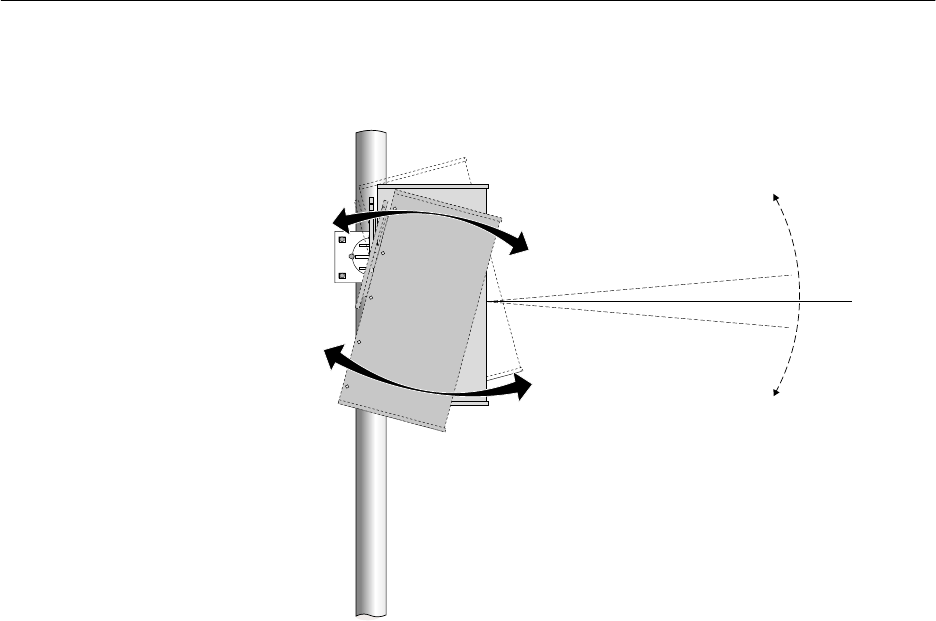
To adjust the antenna elevation (upward or downward pointing
direction), you rotate the antenna upward or downward, as
illustrated in figure 4-15, until the elevation is set as desired.
Antenna
(front)
Side view
0 elevation°
Downward
elevation
Upward
elevation
T0006035
Figure 4-15 Antenna elevation adjustment
(upward or downward adjustment)
Adjust the antenna to the elevation angle specified in the
configuration document as follows:
1. Rotate the antenna until its elevation angle (angle from
horizontal) is approximately the same as the specified
elevation angle (typically 0° or near 0°).
If the antenna does not rotate freely, loosen each of the
antenna bracket nuts slightly.
4.8
Adjusting the
antenna elevation
1027145–0001 Revision E Installing ODUs 4–21Hub installation
2. Place an inclinometer on the top surface of the antenna, as
shown in figure 4-16.
Downward elevation angle
(may also be upward, depending on
network configuration)
Antenna
(front)
T0006036
Inclinometer
Figure 4-16 Inclinometer on top of the antenna
3. Adjust the antenna as necessary to obtain the correct
elevation angle, as indicated by the inclinometer.
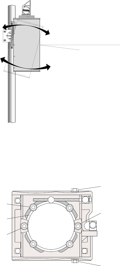
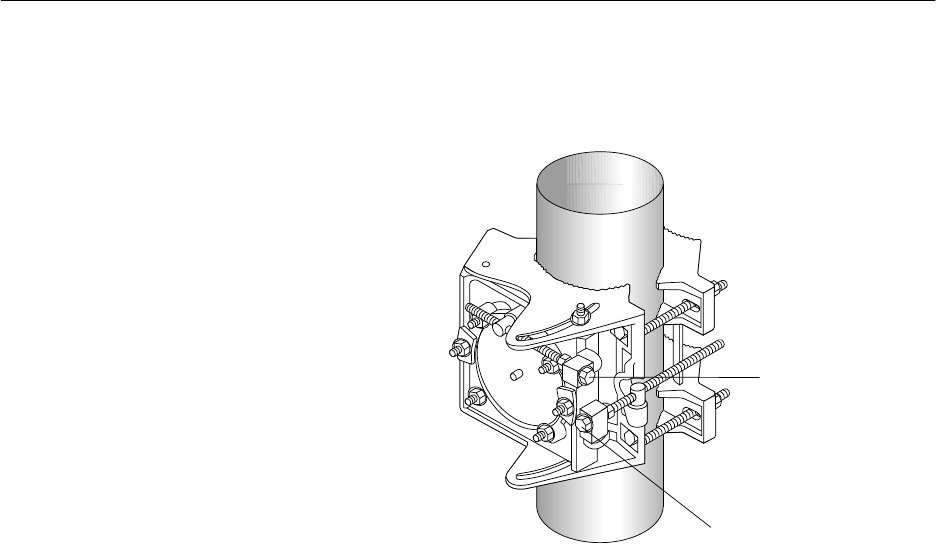
4. When the elevation is properly adjusted, tighten the four
antenna bracket nuts to 16 foot–pounds torque (21.7
Newton–meters). See figure 4-17.
T0009031
Tighten
Tighten
Tighten
Tighten
Antenna bracket
locking nut
Elevation locking nut
(Leave loose for later
adjustment.)
Elevation locking nut
(Leave loose.)
Azimuth locking nut
(Leave loose.)
Azimuth locking nut
(Leave loose.)
Antenna bracket
Figure 4-17 Antenna bracket locking nuts (and other nuts)
1027145–0001 Revision E 4–22 Installing ODUs Hub installation
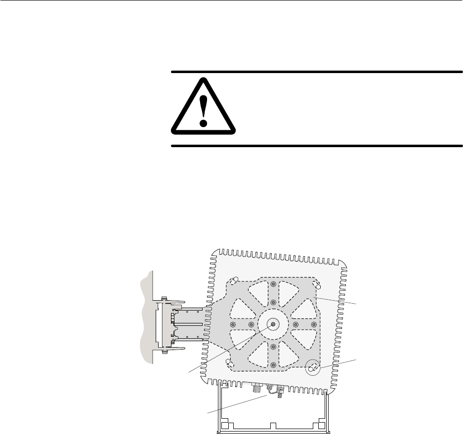
At this point, the mount is tightened to the mast and the antenna is
tightened to the mount. If necessary, you can fine–adjust the
azimuth and elevation using the built–in adjusters shown in figure
4-18.
T0009034
Fine azimuth
adjuster
Fine elevation
adjuster
Figure 4-18 Fine azimuth adjuster and fine elevation adjuster
1. Use a compass or protractor to determine if the antenna
azimuth needs to be fine–adjusted.
Note: Accurate azimuth adjustment is especially important
for the 22.5° HT antenna. (Sectors are smaller and must be
set up precisely to achieve correct coverage.)
2. If azimuth adjustment is necessary, use a wrench to slowly
rotate the fine azimuth adjuster (shown in figure 4-18) until
the azimuth is set correctly.
1. Use the inclinometer to determine if the antenna elevation
needs to be fine–adjusted.
2. If elevation adjustment is necessary, use a wrench to slowly
rotate the fine elevation adjuster (shown in figure 4-18)
until the elevation is set correctly.
1. When both azimuth and elevation are adjusted
correctly, tighten the azimuth and elevation locking nuts
(figure 4-17) to 16 foot–pounds (21.7 Newton–meters)
torque.
At this point, antenna installation is complete, and the
antenna is aligned. Section 4.10 explains how to attach the
transceiver to the antenna.
4.9
Making fine
adjustments
Azimuth
Elevation
Final tightening
1027145–0001 Revision E Installing ODUs 4–23Hub installation
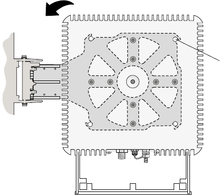
Follow these steps to attach the transceiver to the antenna:
1. Remove the plastic plug from the antenna waveguide and
the plastic cap from the transceiver coupling.
CAUTION
Always keep the waveguide and coupling
plugs in place when the transceiver is
detached from the antenna, to prevent
contamination.
2. Position the transceiver so the three connectors point
downward and its four mounting bolts are aligned with the
four grooves on the antenna bracket, as shown in figure
4-19.
T0006037
Transceiver
Antenna bracket (between
antenna and transceiver)
Waveguide
Antenna
Some antenna models may be
smaller than the antenna shown here.
Groove and
mounting bolt.
(Bolts are attached
to transceiver.)
Connectors
Figure 4-19 Aligning the transceiver mounting bolts
4.10
Attaching the
transceiver to the
antenna
1027145–0001 Revision E 4–24 Installing ODUs Hub installation
3. Rotate the transceiver, making sure the transceiver’s
mounting bolts slide into the grooves in the antenna bracket.
(The direction of rotation depends on the orientation of the
antenna bracket—to the right or left.) If the mounting bolts
will not slide into the grooves, loosen the bolts. See figure
4-20.
T0006038
Mounting bolts must be
fully inserted in grooves.
Rotate transceiver to slide bolts into grooves.
(Rotation direction depends on orientation
of antenna bracket to right or left.)
Figure 4-20 Transceiver (installed)
4. Tighten the mounting bolts.
5. After tightening the transceiver, use the sector map,
protractor, and inclinometer to make sure the azimuth and
elevation adjustments are correct.

1027145–0001 Revision E Installing ODUs 4–25Hub installation
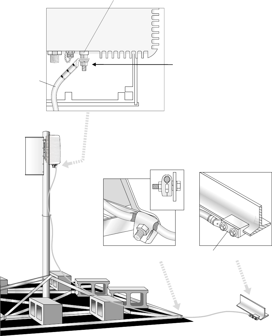
Grounding the ODU requires several connections, as shown in
figure 4-21. In making the ground connections, follow these
practices:
•For all ODU ground connections, use compression
connectors (such as compression lugs or compression
clamps).
•For all threaded ground connections, use a flat washer and
lock washer (with the lock washer next to the nut).
Ground the ODU as follows:
1. Connect one end of the ground cable (No. 6 AWG or
greater, green) to the ODU ground connector, which is
shown in figure 4-21.
2. Connect the ground cable to a bolted joint on the mast
mount.
Important: For this connection, strip the cable but do not
cut it. See figure 4-21. The cable continues from the bolted
joint to the ground point.
3. Connect the ground cable to a suitable ground point on the
rooftop.
The best ground point for the ODU is an earth–referenced
roof ring conductor that follows the perimeter of the
building, constructed according to the requirements of
NFPA 780 or a similar regulatory code. However, such a
conductor is not always present. Other alternatives are
acceptable, as long as they comply with the grounding
requirements detailed in the Hub and Remote Terminal Site
Preparation Guide.
Building steel can also be used as a ground point. However,
before using building steel, verify that the steel structure
is electrically continuous throughout the entire building
and that it is properly connected to earth ground. For
detailed grounding requirements, see the Hub and Remote
Terminal Site Preparation Guide.
4. Apply anti–oxidant (HNS 9008224–0002) to each ground
lug (points 1, 2, and 3 in figure 4-21).
5. Apply 1/2–inch (13–millimeter) heat shrink tubing (HNS
9007488–0005) to each ground lug after the connection is
complete.
Important: You must slip the heat shrink onto the cable
before you make the connections.
Note: A resistance of less than 5 ohms is desirable from the
ODU to earth, including the earth field.
4.11
Grounding the ODU
1027145–0001 Revision E 4–26 Installing ODUs Hub installation
T0006011
Antenna
Transceiver
Ground
point
Ground
cable
ODU
Side view
2-hole compression lug
(Shown: Bond to structural steel)
Ground point
on roof
3.
Apply anti-oxidant
and heat shrink to
all ground lugs.
Single-hole
compression lug
End view
Clamp-type ground connector.
Strip cable at clamp.
Bolted joint on
mast mount
2.
Ground cable
No. 6 AWG
or greater
ODU ground connector
1.
View from rear
Transceiver
Figure 4-21 ODU grounding connections
Lightning protection is provided by grounding the ODU as stated
above and installing a lightning arrestor where the IFL cable
enters the roof (as explained in section 5.7). The ODU ground
and IFL lightning arrestor must both be bonded to the same
ground (reference) point.
Lightning protection
HUB INSTALLATION
1027145–0001 Revision E Installing IFL cables 5–1
Hub installation
Chapter 5
Installing IFL cables
This chapter includes:
•IFL cable specifications – page 5–2
•Overview: IFL plan – page 5–3
•Determining the IFL cable route – page 5–4
•Penetrating the roof – page 5–5
•Installing the penetration sleeve – page 5–6
•Installing the IFL cable inside the building – page 5–7
•Installing the hub lightning arrestor – page 5–8
•Installing the IFL cable on the roof – page 5–13
•Testing the IFL cable – page 5–15
•Connecting the IFL cable to the ODU – page 5–15
Appendix C covers IFL cable termination in detail.
DANGER
Do not work on a ladder or roof without
first reading the safety warnings on page x
of this manual. Failure to observe these
warnings could result in personal injury or
death.
Note: The lightning arrestor and penetration sleeves referred to
and illustrated in these instructions are not specific parts available
from HNS. They are presented to illustrate a typical solution for
providing grounded lightning arrestor protection for one or more
IFL cables. Other solutions are acceptable as long as they comply
with the IFL grounding requirements specified in the Hub and
Remote Terminal Site Preparation Guide.

1027145–0001 Revision E 5–2 Installing IFL cables Hub installation
The intrafacility (IFL) cable specified for AIReach Broadband
installations is a Type 3 coaxial cable, HNS 1010812–0001
(1,000–foot / 305–meter spool). This cable is non plenum, CMG
UL/C (UL) approved. An acceptable alternative is LMR–400
plenum cable (available from Times Microwave Systems,
Wallingford, CT). For additional specifications, see the Hub and
Remote Terminal Site Preparation Guide.
The following Underwriters Laboratories (UL) requirement
applies to the IFL cable:
The IFL cable must be installed in a
metal conduit and grounded according
to NEC article 800–40. If the IFL cable will
not be installed in a metal conduit, the
cable must be a plenum cable, UL/C(UL)
approved, with a CMR rating (or higher).
For specific grounding instructions, see Grounding the lightning
arrestor in section 5.7. Refer also to the grounding guidelines
included in the Hub and Remote Terminal Site Preparation Guide.
5.1
IFL cable
specifications
1027145–0001 Revision E Installing IFL cables 5–3
Hub installation
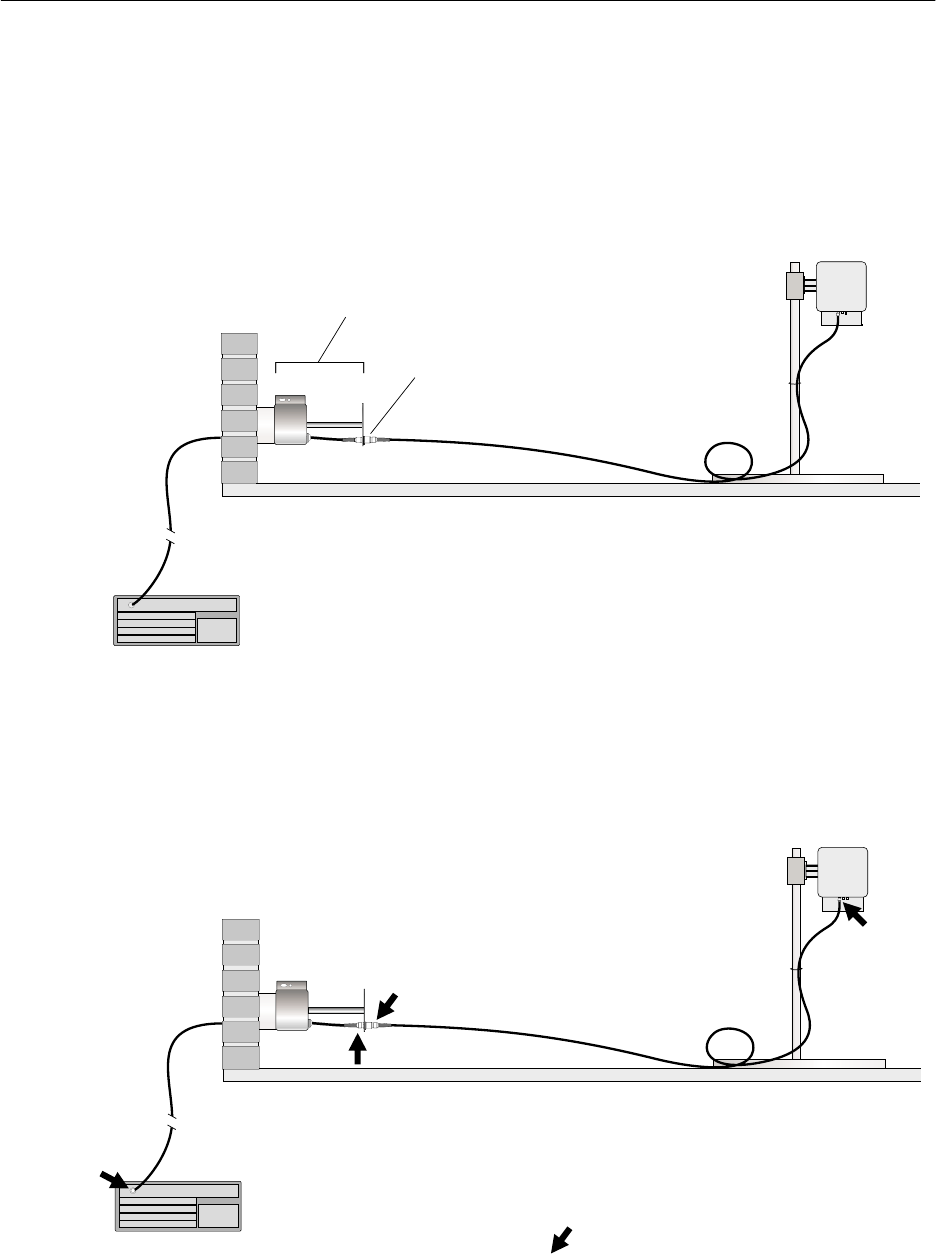
Figure 5-1 shows the IFL and lightning arrestor. A lightning
arrestor is required on the roof at the IFL building
penetration point.
Figure 5-1 shows how the IFL cable is installed in two segments
to accommodate the lightning arrestor:
•One segment from the IDU to the rooftop lightning arrestor
•One segment from the lightning arrestor to the ODU
ODU
IFL
(cable segment 2)
RF
arrestor
T0006058
IFL
(cable
segment 1)
Roof
IDU (not installed yet)
(Not to scale)
Lightning arrestor
assembly
Figure 5-1 IFL plan
Because the IFL cable is installed in two segments, it is cut and
terminated (with an N–type connector) in four locations, as shown
in figure 5-2.
ODU
IFL
Lightning
arrestor
T0006013
IFL
Roof
IDU
N
N
N
N
N= N connector location
Figure 5-2 Four locations where N connectors are installed
5.2
Overview: IFL plan
IFL connections

1027145–0001 Revision E 5–4 Installing IFL cables Hub installation
Detailed instructions for installing the IFL and lightning arrestor
are included in the following sections.
Determine the IFL cable route, from IDU to ODU. Consider the
guidelines below. Every building and rooftop is unique; for this
reason, some of these guidelines may not apply to your
installation:
•The most important considerations are the ODU and IDU
locations and the building entry point. The entry point
should be as close as possible to the ODU. Refer to the HT
rooftop drawings. See also page 3–3.
•The maximum IFL cable length is 1000 feet (305 meters).
•Where possible, use existing conduit.
•You must use a pull box to facilitate pulling cables through
conduits if routing cable through bends totaling more than
360°.
•If existing conduits can not be used and the cable will be
exposed, refer to building codes to determine proper cable
insulation type. For example, plenum rated cable must be
used if cable will be run above suspended ceilings.
•If you are installing the IFL cable(s) inside a conduit
that contains power cables, you must use plenum–rated
cable.
•Look for cable routes that will be easily accessible, such as
stacked telco closets etc.
•Older buildings may not have stacked telco closets. You
may have to route the cable back and forth, from one side of
the building to the other.
•Never run the IFL cable across corrugated roofing. Run the
cable in the corrugation trough:
hb009
Roof
Yes No
Cable
5.3
Determining the IFL
cable route

1027145–0001 Revision E Installing IFL cables 5–5
Hub installation
Follow the steps below to drill a hole for the IFL cable only when
there is not an existing entry you can use.
1. Go to the roof.
2. Determine where the IFL cable will penetrate the roof.
Refer to the HT rooftop drawings.
Before you drill, consider these guidelines:
•Important: Do not penetrate any part of the building
structure without first making sure you have the explicit
permission of the customer and building owner.
•Horizontal penetration is preferable to vertical penetration.
(A horizontal hole is less likely to leak.)
•Take care not to destroy cabling or wiring under the roof or
inside the wall.
•Round penetration holes are preferred over square holes.
(They are easier to make and seal.)
3. Drill a 5–inch (127–millimeter) diameter hole at the
building penetration point.
Building
penetration
point
Building surface
5 inches
(127 millimeters) hb085
5.4
Penetrating the roof
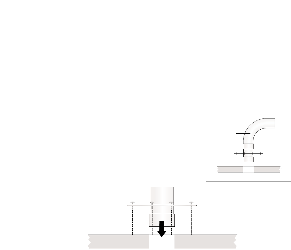
1027145–0001 Revision E 5–6 Installing IFL cables Hub installation
The IFL cable must be routed through a penetration sleeve before
it is connected to the lightning arrestor. The lightning arrestor is
attached to the penetration sleeve after cable installation.
1. Use twelve screws to attach the hub penetration sleeve
(sleeve and coupling) to the building surface at the building
penetration point. See figure 5-3.
The type of screw used depends on the roof thickness and
surface composition. The screws must hold the sleeve
securely.
Note: If space is limited, use a 90° sweep, as illustrated in
in figure 5-3.
Screws
(12 total)
Building
penetration
point
T0006059
Penetration sleeve
with sweep
Sweep
Figure 5-3 Installing the hub penetration sleeve
2. Weatherproof the penetration sleeve by applying silicone
caulk or other weatherproofing material to the bolt hole
areas and the surface of the sleeve plate.
Note: Silicone caulk may not be suitable for certain types
of roofs.
5.5
Installing the
penetration sleeve
1027145–0001 Revision E Installing IFL cables 5–7
Hub installation
You install the IFL cable in two segments, as shown in figure 5-1
(on page 5–3). To install the first cable segment—from the IDU
chassis location to the lightning arrestor—follow the instructions
and guidelines below. Because every building has unique features,
it is not possible to give exact instructions.
1. Measure the cable run length from the IDU chassis location
to the lightning arrestor location (IFL building entry point).
Allow for routing around obstacles and a service loop
(excess cable, in case there is any reason to later cut and
re–terminate the cable).
2. Run the cable from the IDU chassis location, through an
existing conduit if possible, through the hub penetration
sleeve (figure 5-3), to the lightning arrestor location.
Use a stand so the cable spool spins freely as it is pulled.
Leave a service loop.
CAUTION
Avoid making sharp bends in the IFL cable.
The minimum bend radius for IFL cable is 2
inches (51 millimeters). Sharper bends may
cause permanent damage to the cable.
3. Cut the cable at the IDU chassis location and at the
lightning arrestor.
Important: Cut the cable 2 feet (0.6 meters) beyond the
lightning arrestor location (building penetration point).
4. Terminate the cable end at the IDU chassis location with an
N–type connector. For detailed instructions for connecting
an N connector, see appendix C.
Important: Sound IFL cable connections are critical for
proper operation of the AIReach Broadband system.
Therefore, be very careful in terminating the cable. Refer to
the detailed instructions in appendix C if necessary.
Attach N connectors after you route and install the
cable, not before.
Note: The IFL cable installation is completed in section 5.8.
5.6
Installing the IFL
cable inside the
building
1027145–0001 Revision E 5–8 Installing IFL cables Hub installation
All AIReach Broadband IFL cables must connect to a
grounded lightning arrestor at the building penetration point,
as shown in figure 5-1 (page 5–3) and explained in this
section.
WARNING
To help avoid death, injury, or damage from
a lightning strike, you must install a
lightning arrestor where the IFL enters the
building.
Figure 5-4 identifies the components of a typical hub lightning
arrestor. The design illustrated here (see also figure 5-5) can
accommodate up to eight IFL cables for up to eight HTs.
Figure 5-4 Typical hub lightning arrestor
Restraining
fitting
Ground bar
RF arrestor
hb077
Go to the roof to install the lightning arrestor.
5.7
Installing the hub
lightning arrestor
1027145–0001 Revision E Installing IFL cables 5–9
Hub installation
Follow these steps to route the IFL cable through the lightning
arrestor and connect the cable to the RF arrestor:
1. Attach an RF arrestor to the arrestor body with a 3/4–inch
(19–millimeter) nut. See figure 5-5.
The illustrated hub lightning arrestor design can
accommodate up to eight RF arrestors, to provide protection
for up to eight IFL cables.
hb078
3/4-inch
(19-millimeter)
nut
Top of lightning arrestor, showing
holes for 8 RF arrestors
Figure 5-5 Attaching the RF arrestor to the arrestor body
Connecting the IFL
cable to the RF arrestor
1027145–0001 Revision E 5–10 Installing IFL cables Hub installation
2. Route the cable from the IDU chassis location through the
base of the lightning arrestor and the restraining fitting, as
shown in figure 5-6.
Figure 5-6 Routing IFL cable
T0006028
From
IDU
Restraining
fitting
Terminate with
N connector
here.
3. Terminate the end of the IFL cable with an N connector.
For detailed instructions for connecting an N connector, see
appendix C.
4. Connect the cable to the RF arrestor, as shown in figure 5-7.
5. Working from inside the arrestor body, use a wrench to
tighten the restraining fitting.
6. If you are installing additional IFL cables, repeat steps 1
through 5
hb080
RF arrestor
Figure 5-7 Connecting the IFL cable to the RF arrestor
1027145–0001 Revision E Installing IFL cables 5–11
Hub installation
Attach the lightning arrestor to the penetration sleeve:
1. Slide the lightning arrestor over the sleeve, as shown in
figure 5-8.
2. Fasten the lightning arrestor to the sleeve with a screw.
Figure 5-8 Attaching the lightning arrestor to the sleeve
hb083
Slide the lightning arrestor
over the sleeve.
Attaching the arrestor
to the penetration
sleeve
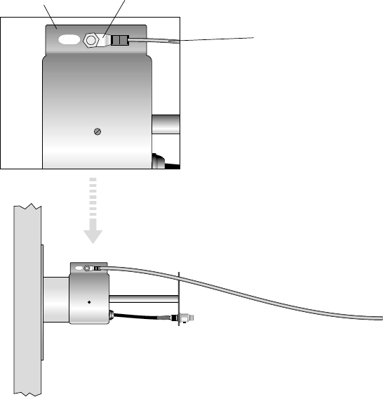
1027145–0001 Revision E 5–12 Installing IFL cables Hub installation
Follow these steps to ground the lightning arrestor:
1. Connect one end of the ground cable (No. 6 AWG or
greater, green) to the lightning arrestor ground bar, as
shown in figure 5-9.
hb097
To ground
point
Ground cable
No. 6 AWG or greater
Single-hole compression lug
Ground bar
Figure 5-9 Hub lightning arrestor grounding connections
2. Route the ground cable to the ground point.
When routing the ground cable, you must:
•Secure the ground cable at 5–foot (1.5–meter)
intervals.
•Keep the ground cable at least 3 feet (0.9 meters)
away from non–grounded metal objects.
•Make sure all bends in the cable have a sweeping
radius of more than 8 inches (20.3 centimeters).
3. Connect the hub lightning arrestor to the same ground
(reference) point as the ODU ground. See section 4.11.
4. Apply anti–oxidant (HNS 9008224–0002) to each ground
lug.
5. Apply 1/2–inch (13–millimeter) heat shrink tubing (HNS
9007488–0005) to each ground lug after the connection is
complete.
Important: You must slip the heat shrink onto the cable
before you make the connections.
Grounding the lightning
arrestor
1027145–0001 Revision E Installing IFL cables 5–13
Hub installation
To install the second IFL cable segment—from the lightning
arrestor to the ODU—follow the instructions and guidelines
below. Because every rooftop has unique features, it is not
possible to give exact instructions.
Connect the IFL to the lightning arrestor as follows:
1. Measure the cable run length from the lightning arrestor to
the ODU. Allow for routing around obstacles and a service
loop (excess cable, in case there is any reason to later cut
and re–terminate the cable).
2. Run the cable from the lightning arrestor to the ODU.
Leave a service loop.
CAUTION
Avoid making sharp bends in the IFL cable.
The minimum bend radius for IFL cable is 2
inches (51 millimeters). Sharper bends may
cause permanent damage to the cable.
3. Cut the cable at the lightning arrestor and at the ODU.
4. Terminate both ends of the cable segment with N
connectors. For detailed instructions for connecting N
connectors, see appendix C.
5.8
Installing the IFL
cable on the roof
Connecting to the
lightning arrestor
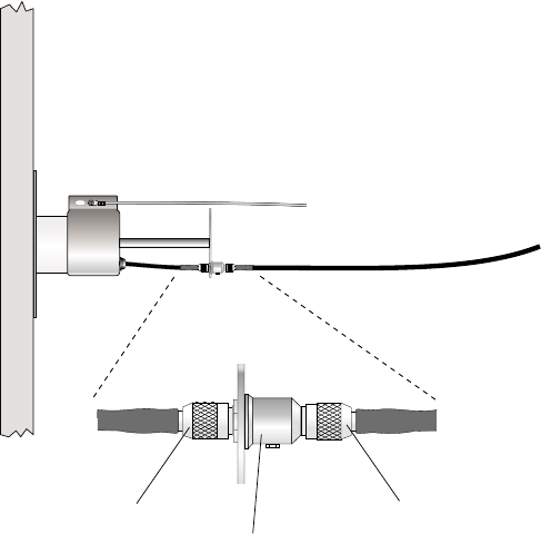
1027145–0001 Revision E 5–14 Installing IFL cables Hub installation
5. Connect the cable to the RF arrestor, as shown in figure
5-10.
Figure 5-10 Connecting the IFL to the RF arrestor
hb084
Ground wire
IFL
To ODU
N connector
RF arrestor
N connector
Note: The IFL cable is connected to the IDU after the CCM and
SSIs are installed (chapter 6).
Do not apply permanent weatherproofing until the HT has
been tested and commissioned. If the weather is wet or windy,
a temporary tape seal is recommended. Weatherproofing is
covered in section 8.1.
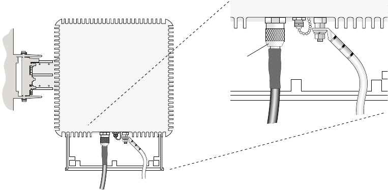
1027145–0001 Revision E Installing IFL cables 5–15
Hub installation
Test the IFL cable and connectors as follows:
1. Check each connector: Use a multimeter or continuity tester
to check for continuity (a short circuit) between the center
conductor and the connector body (outer shell).
If the meter or tester does not indicate an open (no
connection), the connector or cable is defective and must be
replaced.
2. Check the connectors and cable:
a. Using a small jumper cable, attach a jumper clip to
the center conductor of the connector on one end of
the cable.
b. Attach the other end of the jumper to the connector
body, so the center conductor and connector body
make electrical contact.
c. At the other end of the cable (at the IDU location),
use a multimeter to measure the resistance between
the center conductor and connector.
Resistance should be less than 10 ohms. If it is
greater than that find and correct the problem.
1. Connect the IFL to the ODU as shown in figure 5-11.
T0006039
IFL
Ground
wire
Rear view
N connector
Figure 5-11 Connecting the IFL to the ODU
2. Apply electrical tape to the N connector for temporary
protection against moisture contamination.
Do not apply permanent weatherproofing until the HT
has been tested and commissioned. If the weather is wet
or windy, a temporary tape seal is recommended.
Weatherproofing is covered in section 8.1.
Testing the IFL cable
Connecting to the ODU

1027145–0001 Revision E 5–16 Installing IFL cables Hub installation
After running the cable, finish the cable installation as follows:
1. Support the cable above the roof surface with a cable trough
or wood blocks approximately 4 inches by 4 inches by 4
inches (10 centimeters by 10 centimeters by 10
centimeters):
hb010
2. Tie down cable runs on the roof and at the IDU location
with tie–wraps.
3. Seal the IFL rooftop entry point with weatherproofing
caulk.
4. Label both ends of the IFL cable to identify the cable in an
appropriate manner. This is especially important if you are
installing multiple IFL cables. (To order IFL labels, request
HNS part number 9005328–0055.)
Finishing the cable
installation

HUB INSTALLATION
1027145–0001 Revision E Installing indoor hub equipment 6–1Hub installation
Chapter 6
Installing indoor hub equipment
This chapter includes:
•Installing the hub rack – page 6–2
•Installing indoor units (IDUs) – page 6–7
•Power supplies – page 6–11
•Installing the CCM – page 6–26
•SSIs – page 6–28
•Connecting the IFL to the CCM – page 6–33
•CCM redundancy bus cable – page 6–34
•Front panel LCD operation – page 6–35
•CCM power–on test – page 6–37
•Hub LAN router and LAN hub – page 6–39
For IDU standards compliance information, see appendix B
(page B–3).
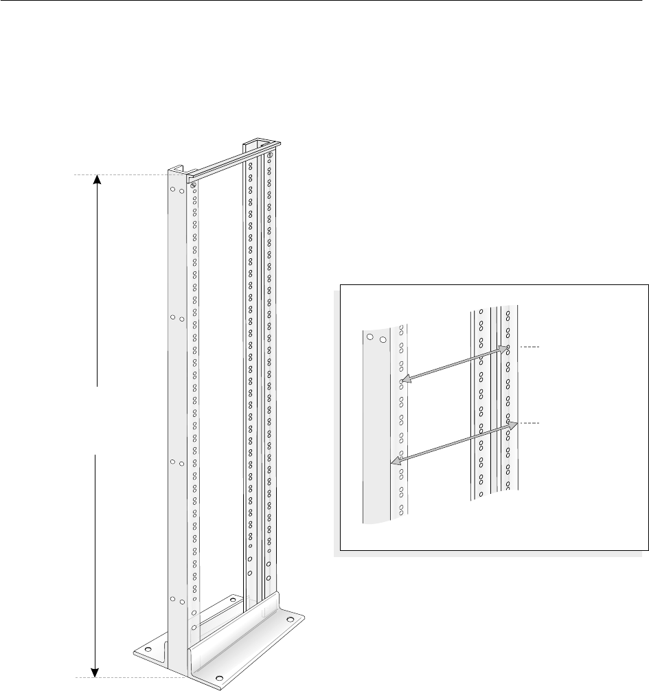
1027145–0001 Revision E 6–2 Installing indoor hub equipment Hub installation
The optional hub rack (figure 6-1) provides a location for
mounting:
•IDUs (8 maximum)
•A dc power distribution unit
•The hub LAN router
Figure 6-1 Optional hub rack
hb076
Capacity:
8 IDUs (allowing for power distribution
unit and space for cabling)
Base (insulator plate):
16 by 20 inches
(40.6 by 51.4 centimeters)
¼
Height:
7 feet
(2.1 meters)
Mounting holes:
18-5/16 inches
(approximately
46.4 centimeters)
Overall:
20-5/16 inches
(approximately
51.5 centimeters)
Rack width
Follow these instructions to install the hub rack—if the hub plans
call for a rack or racks:
1. Refer to the hub plans and drawings to determine where the
rack should be installed.
6.1
Installing the hub
rack (optional)
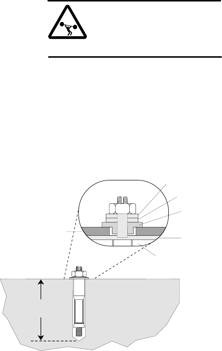
1027145–0001 Revision E Installing indoor hub equipment 6–3Hub installation
2. Remove the hub rack assembly from its shipping container.
WARNING
The optional hub rack weighs approximately
115 pounds (52.2 kilograms) empty. Do not
attempt to lift it by yourself. Two people
should lift or move the rack, when necessary.
Failure to observe this warning could result
in personal injury.
3. Place the isolation pad (HNS 1018302–0001) where the
rack will be installed, and mark the anchor hole locations on
the floor with a pencil.
4. Using a hammer and center punch, mark the center of each
mounting hole location.
• Follow steps 5 through 11 if the floor is concrete:
(If the floor is wood, skip to step 12.)
5. Using a 1-inch carbide-tipped drill bit, drill a hole 5 1/2
inches (14 centimeters) deep in each of the locations you
marked in step 4. See figure 6-2.
Figure 6-2 Installing safety bolts into a concrete floor
hb028
Nut
Rack mounting
bracket
Metal conical washer
Metal washer
Isolation
shoulder
washer
Isolation
pad
Floor
Concrete floor
5-1/2 inches
(14 centimeters)

1027145–0001 Revision E 6–4 Installing indoor hub equipment Hub installation
6. Clean out the holes and position the isolation pad and rack
mounting bracket over the holes as shown in figure 6-2.
7. Remove the nut and washers from each safety bolt, if used,
and place the appropriate washers on the shaft, as shown in
figure 6-2. Then drop a safety bolt into the hole.
CAUTION
When installing the isolation shoulder
washer, make sure the shoulder seats
completely into the metal floor mounting
bracket. Isolation may be compromised if
this washer is damaged or improperly
installed.
8. Use a torque wrench to tighten each safety bolt to
15 foot–pounds (20.3 Newton–meters) of torque.
The slotted sleeve on the safety bolt will be forced against
the walls of the hole, anchoring the safety bolt securely.
Note: If you do not have a torque wrench, use a ratchet
wrench to tighten the safety bolt until the conical washer
(shown in figure 6-2) flattens completely.
9. Once the anchor is set, loosen the nut and insert a flat–blade
screwdriver into the threaded rod slot.
10. Hold the nut with a 1–1/16–inch open–end wrench while
turning the screwdriver clockwise until the top of the rod is
even with the top of the nut.
11. While holding the screwdriver in this position, tighten the
nut.
The threaded rod and the top of the nut will be flush.
• Follow steps 12 through 15 if the floor is made of wood:
12. Using a 5/16-inch drill bit, drill a hole at least 2 inches (5
centimeters) deep in each of the locations you marked in
step 4.
13. Clean out the holes and position the isolation pad and rack
mounting bracket over the holes, as shown in figure 6-3.
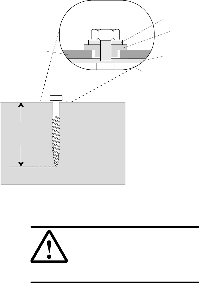
1027145–0001 Revision E Installing indoor hub equipment 6–5Hub installation
Figure 6-3 Installing lag bolts into a wood floor
hb029
Rack
mounting
bracket
Metal washer
Isolation
shoulder
washer
Isolation
pad
Floor
Wood floor
Minimum depth:
2 inches
(5 centimeters)
Lag bolt
14. Place the washers shown in figure 6-3 onto the lag bolt.
CAUTION
When installing the isolation shoulder
washer, make sure the shoulder seats
completely into the metal floor mounting
bracket. Isolation may be compromised if
this washer is damaged or improperly
installed.
15. Use a ratchet wrench and 3/4–inch socket to tighten the lag
bolt.
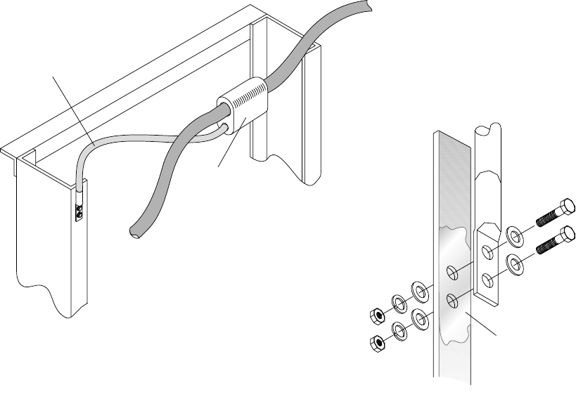
1027145–0001 Revision E 6–6 Installing indoor hub equipment Hub installation
Ground the rack as shown in figure 6-4:
1. Run a ground wire from the rack location to the master
ground bar in the equipment room. This wire must be No. 2
AWG, green, stranded, and shielded.
2. Ground the rack by connecting a No. 6 AWG wire from the
rack to the No. 2 AWG ground wire.
Use a 2–hole lug to connect the No. 6 AWG wire to the
rack. Remove paint and apply anti–oxidant as shown in the
illustration.
T0006050
Top of rack
from rear
Lug connection
close up view
Frame
lug
Remove paint to
bare metal, on
both sides, and
apply anti-oxidant.
Metal rack
HTAP connector
with cover
No. 2 AWG wire
(green) to master
No. 6 AWG wire
Frame
lug
To a subsequent
rack (if present)
Figure 6-4 Grounding the hub rack
This completes mounting and grounding of the hub rack. The rack
is now ready for loading with IDU chassis, power distribution,
LAN hub, and hub LAN router. Configurations vary, according to
the requirements of the customer’s network.
Grounding the rack
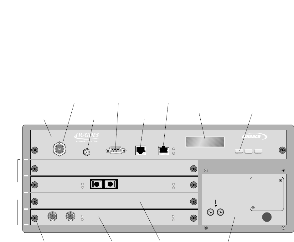
1027145–0001 Revision E Installing indoor hub equipment 6–7Hub installation
Figure 6-5 shows the HT IDU, which consists of the IDU chassis,
the channel and control module (CCM), and service–specific
interfaces (SSIs). The IDU chassis is shipped with the power
supply installed, but the CCM and SSIs are not installed.
For IDU standards compliance information, see appendix B
(page B–3).
The main components of the IDU are identified in figure 6-5.
1
2
3
4
5
TM
BROADBAND
HUB CCM
SSI
slots
IFL
interface
LAN
interface
Maintenance
port
T00006040
Channel and
control module
(CCM)
Service-specific
interface (SSI)
Blank panelThumbscrew DC power supply
Liquid crystal
display (LCD)
Control pushbuttons
(for LCD)
Auxiliary
IF port
Reference
clock
Power supply may be ac, (as shown
here), or dual mode (ac or dc).
dc
ENTERPREVNEXT
Figure 6-5 HT IDU main components
6.2
Installing IDUs
IDU components
1027145–0001 Revision E 6–8 Installing indoor hub equipment Hub installation
Three IDU chassis types are available, each with a different power
supply option:
Table 6-1 IDU types
IDU type HNS part number
IDU chassis with ac power supply 1026356–0001
IDU chassis with dc power supply
(–48 Vdc) 1026356–0002
IDU chassis with dual mode
(ac or dc) power supply 1026356–0003
The power supply is not user replaceable.
Before you install the IDU chassis, make sure a power source is
available. If it is not, you may have to select a different location
for the IDU or install an electrical receptacle.
Note: The IDU is an industrial product. For safety and security
reasons, it must be installed in an area that is accessible only to
authorized servicing personnel.
The IDU can be used on a tabletop or installed in a 19–inch
(48.3–centimeter) rack. With optional adapter brackets, the IDU
can also be installed in a 23–inch (58.4–centimeter) rack.
Safety guidelines
Observe these guidelines from Underwriters Laboratories Inc.
(UL) when you install IDU chassis in a rack (any rack):
•Make sure the power requirements of the IDU chassis plus
the cumulative power draw of other equipment in the rack
do not overload the supply circuit and/or wiring of the rack.
•The IDU weighs about 20 pounds (about 9 kilograms).
Have someone help you when you lift the IDU chassis to
install it in the rack.
•Always load the rack from bottom to top to ensure a stable
and safe rack.
•Installation of the IDU chassis within the rack system
should not reduce air–flow within the rack.
•The maximum recommended ambient temperature for the
IDU chassis is 50 °C (122°F).
•While installing the IDU chassis into the rack, make sure
you maintain a proper earth grounding for the equipment.
IDU chassis types
Prerequisites
Mounting options
Rack mounting
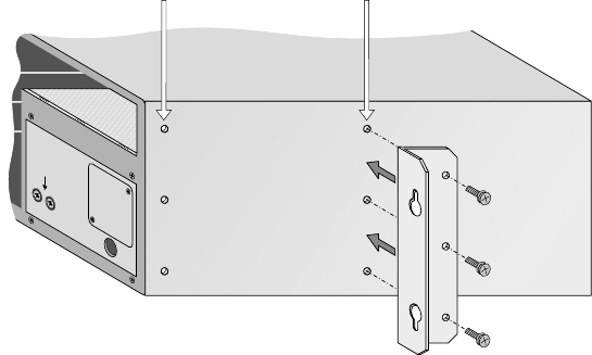
1027145–0001 Revision E Installing indoor hub equipment 6–9Hub installation
Rack mounting instructions
Mount IDU chassis as close to each other as possible to facilitate
cabling.
To mount the IDU chassis in a rack, you need the rack mounting
brackets included in HNS kit 1027191–0001. This kit includes two
brackets and six Phillips SEMS screws for attaching the bracket to
the IDU.
To mount the IDU chassis in a rack, follow these steps:
1. Attach the rack mounting brackets as shown in figure 6-6.
Be sure to use the correct sets of holes (front or midpoint)
for each bracket, as indicated in figure 6-6.
Figure 6-6 Attaching rack mounting brackets to the IDU chassis
hb032
Mounting
bracket
Attach bracket here
for .enclosed rack
Attach bracket here
for .open rack
Front
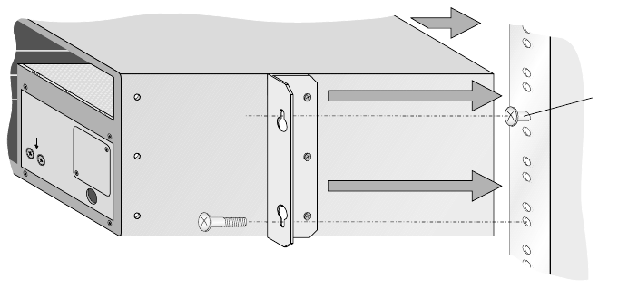
1027145–0001 Revision E 6–10 Installing indoor hub equipment Hub installation
2. Screw the two upper mounting screws into the rack (one on
each side), at the desired installation height. Refer to figure
6-7.
Do not tighten the screws all the way—this allows you to
hang the chassis by the top “teardrop” holes on the brackets
(in step 3).
(The four mounting screws that screw into the rack should
be provided with the rack.)
Figure 6-7 Installing the IDU chassis in a rack
hb033
Rack
Front
Leave part
of the upper
mounting
screws
exposed
so you can
hang the
brackets
on them.
3. Place the chassis into the rack, and slip the top hole of each
bracket over the heads of the upper mounting screws in the
rack.
4. Support the chassis with one hand while you install and
tighten the two lower screws.
5. Tighten the two upper screws.
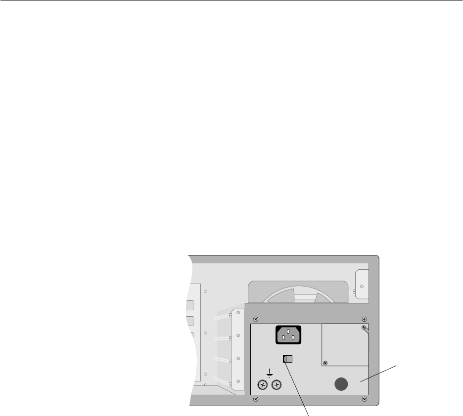
1027145–0001 Revision E Installing indoor hub equipment 6–11Hub installation
The IDU power supply is installed in the chassis at the factory.
However, you need to make sure the power supply is grounded
and connect power to the power supply. Detailed instructions for
these steps follow.
The IDU chassis may be equipped with an ac, dc, or dual (ac or
dc) power supply, depending on the local power environment. In
the following sections, make sure you follow all instructions for
the type of power supply your IDU chassis has.
Do not attempt to replace or substitute power supplies. If there
is a problem with a power supply, return the chassis to HNS for
repair or replacement.
The dual ac or dc power supply (figure 6-8) can be used with an ac
or dc power source. A recessed switch on the front of the power
supply is used to select ac or dc operation.
T0006026
AC DC
Dual ac/dc
power supply
AC/DC switch
Figure 6-8 Dual ac or dc power supply
Selecting ac or dc power
Follow these instructions to set the power supply for ac or dc
operation:
To use the dual power supply with ac power:
Make sure the switch is in the AC position; then follow the
instructions below for ac power supplies.
Note: The AC–DC switch is recessed to prevent accidental
switching. Use a flathead screwdriver to change the switch
position.
To use the dual power supply with dc power:
Make sure the switch is in the DC position; then follow the
instructions below for dc power supplies.
6.3
Power supplies
Power supply options
Dual (ac or dc) power
supply

1027145–0001 Revision E 6–12 Installing indoor hub equipment Hub installation
Labels on dual power supply
A label on the dual ac or dc power supply warns:
WARNING
MULTIPLE POWER
CONNECTORS.
DISCONNECT BOTH
AC & DC POWER
BEFORE SERVICING.
Servicing personnel must heed this warning. Note that the IDU
and power supply should be serviced only by HNS.
A second label on the dual ac or dc power supply advises:
CAUTION
THIS EQUIPMENT HAS A
CONNECTION BETWEEN
THE EARTHED CONDUCTOR
OF THE D.C. SUPPLY CIRCUIT
AND THE EARTHING CONDUCTOR.
SEE EARTHING INSTRUCTIONS
To disconnect dc power, unplug the terminal block (shown on
page 6–19). Do not remove the wires from the terminal block
while it is plugged in. If you do, the IDU chassis will not be
grounded.
Additional instructions
If the power supply is a dual ac or dc unit, follow the instructions
in the following sections for both ac and dc power supplies.
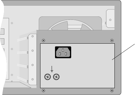
1027145–0001 Revision E Installing indoor hub equipment 6–13Hub installation
IDU chassis with an ac power supply (figure 6-9) or dual ac or dc
power supply are equipped with a recessed IEC–320–C13
connector and a 7.5–foot (2.3–meter) power cable (HNS
9003024–0013). The power cable includes a NEMA 5–15–P plug
to connect to the power source (receptacle). The cable is rated at
125 Vac, 10 amperes, and is equipped with an internal ground
(earth) conductor.
The primary input requirements for the ac power supply are:
Voltage: 100 – 240 Vac
Current: 6.4 amperes maximum
Frequency: 50 – 60 Hz
Figure 6-9 AC power supply
AC power supply
hb048
AC power supply
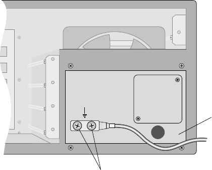
1027145–0001 Revision E 6–14 Installing indoor hub equipment Hub installation
Important: In the United States and some international markets,
the required ground bond is provided by the grounding conductor
in the cable and ac service conductors. If grounding is provided
through the grounding conductor and service conductors, no
additional grounding is required.
In environments where ac grounding conductors are not
available, a separate bonding conductor is required.
If a separate bonding conductor is required, ground the ac power
supply as follows:
1. Use a 2–hole lug to connect a No. 16 AWG ground wire to
the ground terminals on the front of the power supply. See
figure 6-10.
T0006049
DC power supply
Ground terminals
Figure 6-10 Ground terminals on ac power supply
2. Connect the other end of the ground wire to the rack ground
bar. If the IDU chassis is not rack mounted, connect the
ground wire to a ground point such as a water pipe or
building steel.
Grounding the ac IDU
chassis
1027145–0001 Revision E Installing indoor hub equipment 6–15Hub installation
WARNING
The IDU chassis must be solidly bonded to a
low–impedance ground (earth) source.
To avoid the risk of electric shock and/or
equipment damage, do not apply power to
the IDU chassis without a ground reference.
CAUTION
If the ODU and lightning arrestor are not
connected to the IFL, do not power on the
IDU chassis without first making sure the
IFL is not connected to the IDU chassis.
Failure to observe this instruction could
result in damage to the equipment.
To connect ac power:
1. Measure the voltage level of the power source to make
sure it can accommodate the total IDU and ODU power
requirements.
(The IDU supplies power to the ODU through the IFL.)
If the voltage level cannot accommodate the IDU and ODU,
the power source must be upgraded before you can proceed.
2. Connect the power cable to the IEC–320–C13 connector on
the power supply.
3. Route and secure the cable to avoid physical damage.
4. Connect the plug end of the cable to a dedicated ac power
source.
Important: In the United States, ac–power IDU chassis
must be connected to a dedicated power circuit with a
15–ampere single–pole breaker. The circuit must not
include unrelated equipment.
Connecting ac power
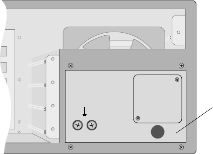
1027145–0001 Revision E 6–16 Installing indoor hub equipment Hub installation
Figure 6-11 shows an IDU chassis with a dc power supply.
A power cable is not supplied with the dc IDU chassis because
cable requirements vary, depending on where the chassis will be
used.
The power input requirement for the dc power supply (and dc
portion of the dual ac or dc power supply) is –42 to –56 Vdc.
hb050
DC power supply
Figure 6-11 DC power supply
Label on dc power supply
A label on the dc power supply advises:
CAUTION
THIS EQUIPMENT HAS A
CONNECTION BETWEEN
THE EARTHED CONDUCTOR
OF THE D.C. SUPPLY CIRCUIT
AND THE EARTHING CONDUCTOR.
SEE EARTHING INSTRUCTIONS
To disconnect dc power, unplug the terminal block (shown on
page 6–19). Do not remove the wires from the terminal block
while it is plugged in. If you do, the IDU chassis will not be
grounded.
DC power supply
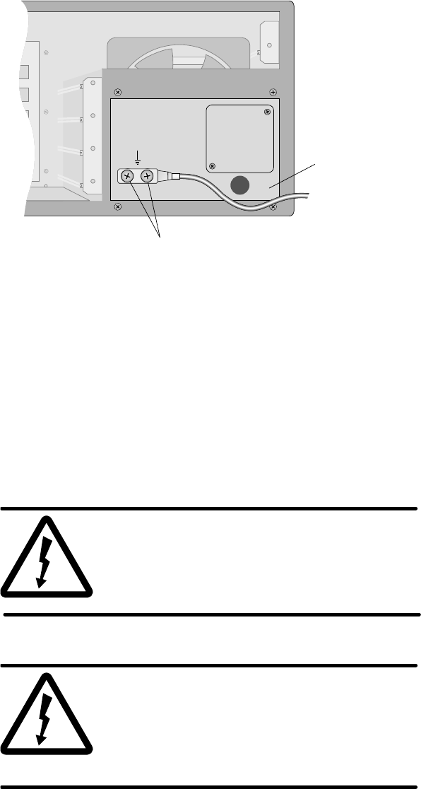
1027145–0001 Revision E Installing indoor hub equipment 6–17Hub installation
Ground IDU chassis with a dc power supply as follows:
1. Use a 2–hole lug to connect a No. 14 AWG ground wire to
the ground terminals on the front of the power supply
(figure 6-12).
T0006049
DC power supply
Ground terminals
Figure 6-12 Ground terminals on dc power supply
2. Connect the other end of the ground wire to the rack ground
bar. If the IDU chassis is not rack mounted, connect the
ground wire to a ground point such as a water pipe or
building steel.
WARNING
To avoid the risk of electric shock,
remove power from the power circuit
before connecting power cables to the
IDU chassis power supply.
WARNING
The IDU chassis must be solidly bonded to a
low–impedance ground (earth) source.
To avoid the risk of electric shock and/or
equipment damage, do not apply power to
the IDU chassis without a ground reference.
Grounding the dc IDU
chassis
Connecting dc power
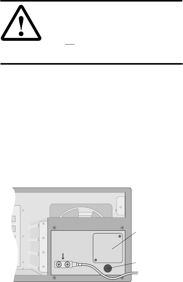
1027145–0001 Revision E 6–18 Installing indoor hub equipment Hub installation
CAUTION
If the ODU and lightning arrestor are not
connected to the IFL, do not power on the
IDU chassis without first making sure the
IFL is not connected to the IDU chassis.
Failure to observe this instruction could
result in damage to the equipment.
To connect power cables from the dc power source (usually a
rectifier) to the dc power supply, follow the steps below.
1. Measure the voltage level of the power source to verify it
can accommodate the total IDU and ODU power
requirements.
(The IDU supplies power to the ODU through the IFL.)
If the voltage level cannot accommodate the IDU and ODU,
the power source must be upgraded before you can proceed.
2. Remove power from the power circuit.
3. Loosen the two Phillips screws from the square terminal
block cover plate on the front of the power supply.
Terminal block
cover plate
(Remove)
T0006051
Conduit opening
4. Rotate the protective plate to expose the terminal block.
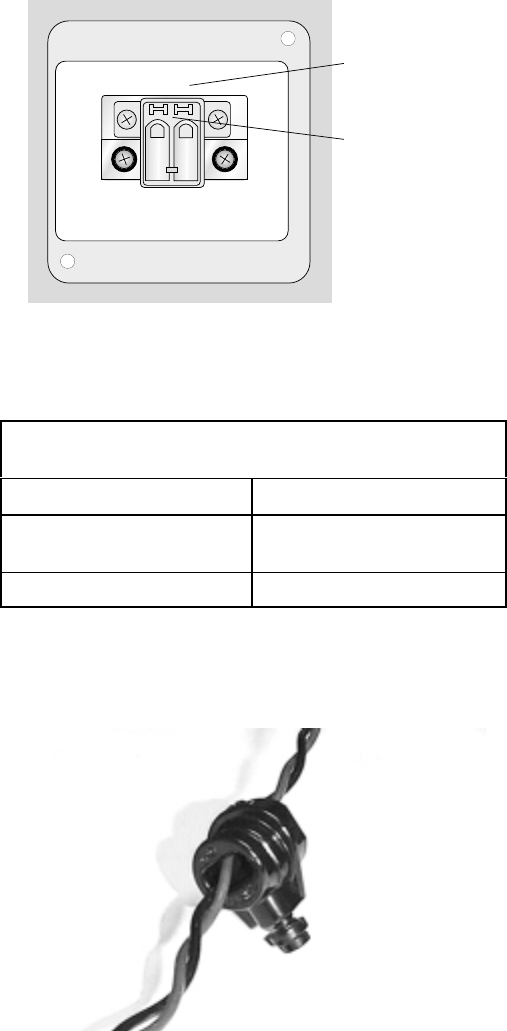
1027145–0001 Revision E Installing indoor hub equipment 6–19Hub installation
• Follow steps 5 through 14 to insert the power cable wires into
the power supply terminal block:
5. Unplug the terminal block from the power supply socket.
hb108
Plug-in terminal
block
Power supply
(+)RETURN
(-)48VDC
6. Strip both wires from the power source to about ¼ inch (6
centimeters) from the end.
Note: Wires used with the terminal block must meet
these specifications:
Composition Solid or stranded
Wire cross–sectional
area 0.2 to 2.5 square
millimeters
Rated gauge 12 to 24 AWG
7. Twist the wires as shown in the photo below.
8. Insert both wires through the plastic strain relief bushing
(HNS 9005614–0001).
Strain relief
bushing
T0006062
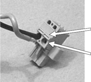
1027145–0001 Revision E 6–20 Installing indoor hub equipment Hub installation
9. Lay the terminal block on a flat surface, with the wire entry
holes facing up.
10. Use a small, flat–blade screwdriver (or similar tool) to press
in the tab above the wire entry hole on the terminal block.
Hold the tab in.
Press and hold
tab to insert wire.
Terminal block with
one wire inserted
Wire entry holes
hb004
11. While holding the tab in, insert the stripped wire end.
Important: Insert the return (+) wire from the dc power source
into the terminal block so it will connect to the power supply
terminal marked (+) Return when the terminal block is plugged
in. Likewise, insert the –48 Vdc (–) wire so it will connect to the
–48 VDC (–) power supply terminal.
12. When the wire is fully inserted, release the tab.
13. Gently tug the wire to make sure it is securely inserted.
14. Repeat steps 10 through 13 for the second wire.
• At this point, both wires are inserted into the terminal block.
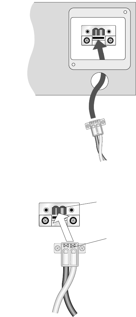
1027145–0001 Revision E Installing indoor hub equipment 6–21Hub installation
15. Insert the terminal block through the conduit opening and
guide it up to the socket.
Socket
Terminal block
Conduit opening
hb051
(+)RETURN
(-)48VDC
16. Plug the terminal block into the power supply terminal
socket.
hb046
(+)RETURN
(-)48VDC
Socket
Terminal block
1027145–0001 Revision E 6–22 Installing indoor hub equipment Hub installation
17. Snap the strain relief bushing into the conduit opening.
18. Tighten the screw on the strain relief bushing just enough to
hold the wires in place. Do not overtighten.
19. Replace the protective plate and tighten the screws.
• This completes the power connections.
The chassis does not have a power off/on switch. In normal
operation, power is always on. If you need to power off the IDU:
•Break the power circuit at the rack fuse panel,
•Break the power circuit at the external fuse or circuit
breaker panel, or
•Use an optional remote power–off circuit.
This section applies only to dc power circuits.
The circuit from the dc power source (usually rectifiers) to the
IDU chassis must include a circuit breaker or other disconnect
device that meets the following Underwriters Laboratories (UL)
requirements:
To install dc power for the IDU chassis, a readily
accessible disconnect device shall be installed
or should be readily available at the site where
the IDU chassis is installed. The disconnect
device must be a UL–listed circuit breaker rated
at 60 Vdc, 6.3 amperes minimum, 15 amperes
maximum.
Powering off the dc IDU
Remote dc
power–off circuit
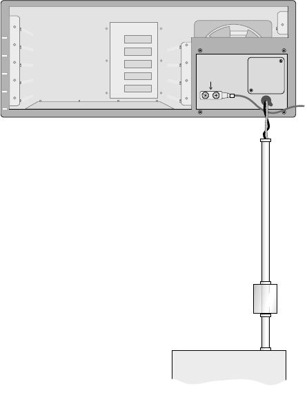
1027145–0001 Revision E Installing indoor hub equipment 6–23Hub installation
If the rectifier–to–chassis power circuit does not include a suitable
circuit breaker, you can satisfy the disconnect requirement by
including a remote power–off switch as shown in figures 6-13 and
6-14. If the power circuit already includes a suitable circuit
breaker, skip this section.
1
2
3
4
5
T0006052
DC power cable
Conduit
Remote
power-off
circuit
Rectifier
IDU chassis
Ground
Figure 6-13 The remote power–off circuit (if needed) is
installed between the IDU chassis and dc power source.
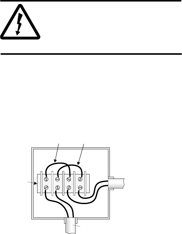
1027145–0001 Revision E 6–24 Installing indoor hub equipment Hub installation
WARNING
To avoid the risk of electric shock, make
sure the dc power source breaker is off
before installing a remote power–off
circuit. Use a continuity tester to verify
that power is off.
To install a power–off circuit (if needed), follow these steps:
1. Make sure the rectifier breaker switch is off.
2. Install a UL–approved terminal block inside a UL–approved
electrical junction box as shown in figure 6-14.
Figure 6-14 Remote power–off circuit
hb001
++
––
Use only UL
listed parts.
Junction
box
Terminal
block
Output from
dc power rectifier
Input to IDU
chassis
Conduit with conduit coupler
Jumper 1 Jumper 2 Use insulated jumpers
connect remote power-off
switch in series.
or
3. Choose one of the following three options:
If you plan to add a power–off switch later, install jumpers 1
and 2, and replace the junction box cover. This completes
the circuit installation.
If you are installing a double–pole remote power–off switch,
use a double–pole, single–throw switch rated at 60 Vdc, 15
amperes (minimum):
In place of jumper 1, wire the switch between the (+)
terminal from the rectifier and the (+) terminal from
the IDU.
In place of jumper 2, and wire the switch between the
(–) terminal from the rectifier and the (–) terminal
from the IDU.
1027145–0001 Revision E Installing indoor hub equipment 6–25Hub installation
If you are installing a single–pole remote power–off switch,
use a single–pole, single–throw switch rated at 60 Vdc, 15
amperes (minimum):
Install jumper 1.
In place of jumper 2, wire the switch between the (–)
terminal from the rectifier and the (–) terminal from
the IDU chassis.
• If you installed a switch, follow steps 4 through 9 to test the
switch:
4. Place the remote power–off switch in the open position.
5. Replace the junction box cover.
6. Turn on the dc breaker.
7. Close the power–off switch. Confirm that the chassis is
receiving power.
8. Open the switch again. Confirm that the chassis is no longer
powered. If the switch does not operate correctly, turn the
rectifier breaker off and make sure the circuit is connected
as shown in figure 6-14.
9. If the switch operates correctly, leave it in the open position
with the breaker off.
Do not install the channel and control module (CCM) or
service–specific interfaces (SSIs) yet.
To test the IDU chassis and power supply, perform these steps
without a CCM or SSIs:
1. If the IDU chassis is dc powered, inspect the power supply
wiring to verify that the polarity is correct.
2. Power on the IDU—with no modules installed; then check
to make sure no breakers have tripped or fuses have blown.
If a breaker trips or fuse blows, be sure to troubleshoot
and correct the problem before proceeding.
Power–on inspection
and test
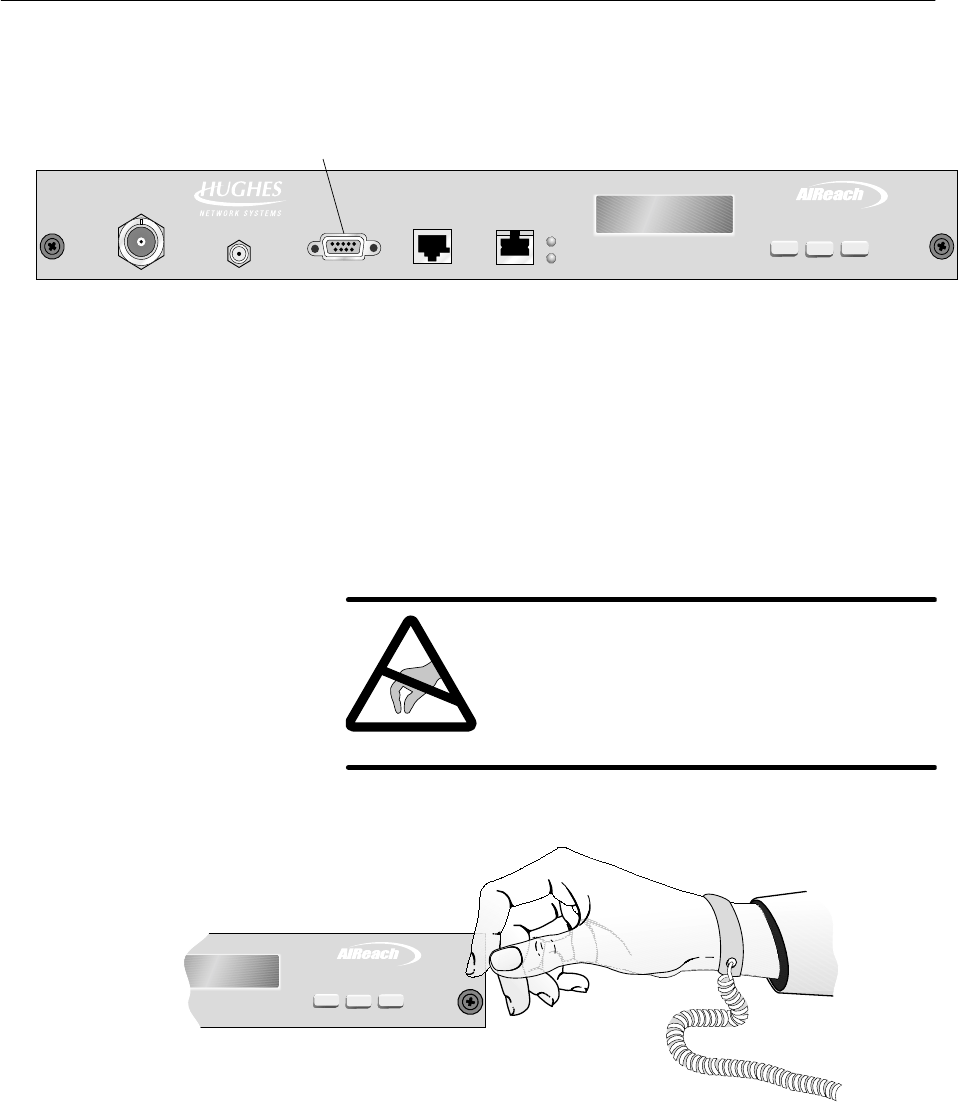
1027145–0001 Revision E 6–26 Installing indoor hub equipment Hub installation
A channel and control module (CCM) must be installed in the top
slot (slot 1) of the IDU chassis. For an HT IDU, the CCM must be
a CCM HT (HNS 1027181–0001), as shown in figure 6-15.
Figure 6-15 CCM HT
TM
BROADBAND
HUB CCM
ENTER
NEXT PREV
Liquid crystal
display (LCD)
Control pushbuttons
(for LCD)
IFL
interface
Reference
clock
LAN
interface
Maintenance
port
Auxiliary
IF port
T0006031
The CCM supports the interface modules installed in the IDU
chassis by performing control, bus, upconversion, and
downconversion functions. These modules—SSIs—are described
in section 6.5.
To install the CCM HT, follow the steps below:
CAUTION
Always wear a new or recently tested
electrostatic discharge (ESD) wrist strap
(figure 6-16) when handling circuit
modules. Failure to use a wrist strap may
result in damage to components.
TM
BROADBAND
ENTERPREVNEXT
T0009051
Wrist
strap
Connect to
IDU chassis
ground terminal.
Figure 6-16 ESD wrist strap
6.4
Installing the CCM
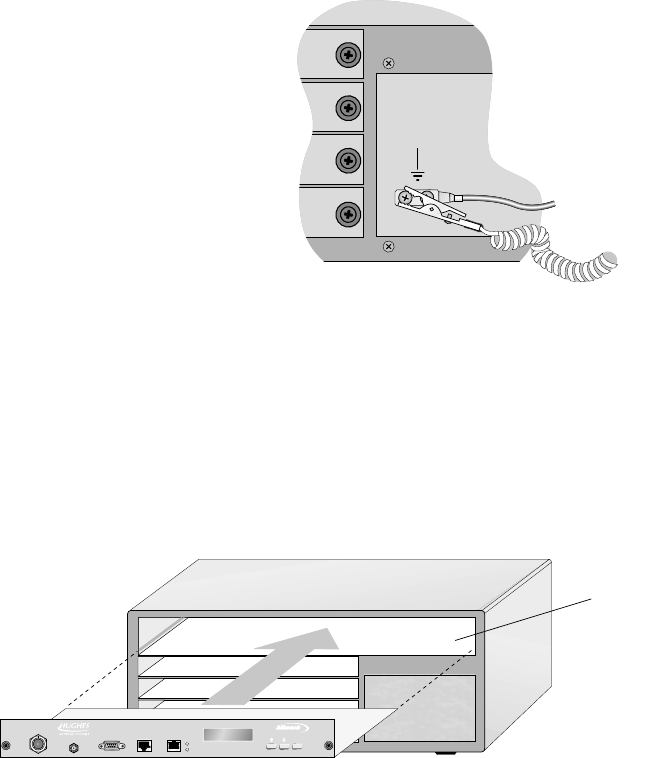
1027145–0001 Revision E Installing indoor hub equipment 6–27Hub installation
1. Wrap the ESD strap snugly around your wrist and connect
the alligator clip to one of the ground terminals on the IDU
chassis power supply.
T0006053
2. Remove the CCM from its ESD protective packaging.
Retain the packaging in case it is necessary to return the
CCM for repair.
3. Slide the module into the guides on each side of the top
chassis module slot (slot 1) and push it firmly into place
until the CCM front panel is flush with the front of the
chassis.
hb064
CCM slot
TM
BROADBAND
ENTER
HUB CCM
4. Tighten the thumbscrews at each end of the CCM.
To tighten the thumbscrews, push them toward the IDU
chassis and turn them clockwise. To fully tighten the
thumbscrews, use a Phillips screwdriver.
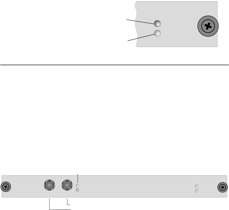
1027145–0001 Revision E 6–28 Installing indoor hub equipment Hub installation
The CCM HT LAN interface (shown in figure 6-15) is an RJ–48
connector that connects the IDU to the hub LAN router, which
provides connectivity to the Element Management System (EMS).
The LAN interface supports 10BaseT, up to 10 Mbps.
The reference clock interface (shown in figure 6-15) is also a
RJ–48 connector. It connects the customer’s clock distribution
network to the IDU. (The EMS operator has to configure the IDU
to accept an external clock.)
The CCM LED indications are explained in the following
illustration:
OK
STATUS
ALARM
()Red
On: Hardware failure
()Green
On: Normal operation
or CCM startup
T0009052
Service–specific interface modules (SSIs) provide interfaces to
support specific network services. SSI types used depend on the
needs of the customer network.
The following SSIs can be installed in the HT IDU chassis:
•DS3–TDM SSI (HNS 1027094–0001)
•OC3c–ATM (HNS 3003136–0003)
•DS3–transparent (HNS 1027094–0002)
The OC3c–ATM SSI is installed in chassis slot 3 only, and the
DS3–TDM SSI is installed in slot 5 only.
The DS3–TDM SSI, shown in figure 6-17, provides a structured
or transparent D3 service link between the HT and RT.
Figure 6-17 DS3–TDM SSI
Tx
ALARM
OK
Rx
TDM SSI
3
DS
T0006022
BNC Rx connector
BNC Tx connector
OK
STATUS
ALARM
SSI status
LEDs
Link status LEDs
The maximum cable length for a DS3–TDM SSI is 450 feet (137.2
meters).
CCM LAN and clock
interfaces
LED indications
6.5
SSIs
DS3–TDM
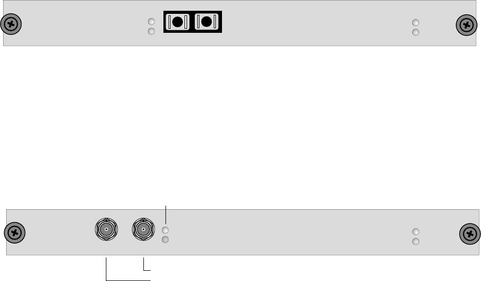
1027145–0001 Revision E Installing indoor hub equipment 6–29Hub installation
The OC3c–ATM SSI, shown in figure 6-18, provides an OC3c
physical interface and provides ATM cell queuing and
multiplexing for over–the–air transmission.
Figure 6-18 OC3c–ATM SSI
T0006047
SSI status
LEDs
Dual SC connector
OC3c SSI
OK
STATUS
ALARM
OK
ALARM
Tx Rx
The maximum cable length for an OC3c–ATM SSI is 1,000 feet
(305 meters).
The DS3–transparent SSI, shown in figure 6-19, provides a direct
point–to–point link between the HT and RT.
Figure 6-19 DS3–transparent SSI
Tx
ALARM
OK
Rx
TRNSPSSI3DS
OK
STATUS
ALARM
T0006023
BNC Rx connector
BNC Tx connector
Link status LEDs
SSI status
LEDs
The maximum cable length for a DS3–transparent SSI is 450 feet
(137.2 meters).
Look at the hub network schematic or other configuration
document to determine:
•How many SSIs to install
•What type(s) of SSIs to install
•Which SSI to install in each IDU chassis slot
Important:
•Install the OC3c–ATM SSI in chassis slot 3 only.
•Install the DS3–TDM SSI in slot 5 only.
OC3c–ATM
DS3–transparent
SSI physical
configuration
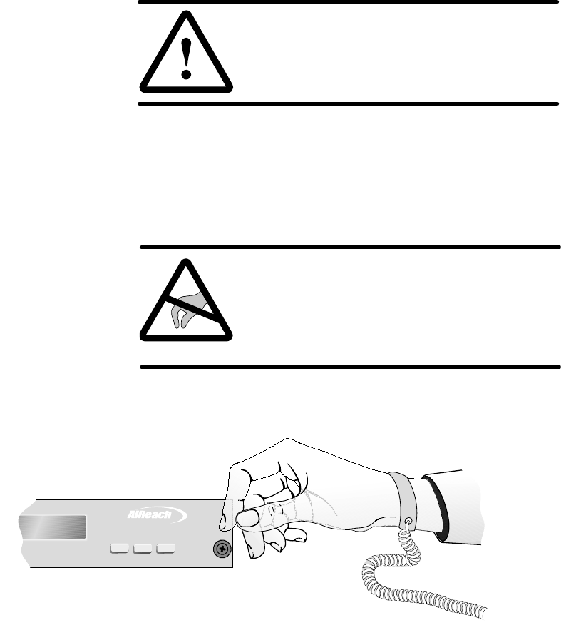
1027145–0001 Revision E 6–30 Installing indoor hub equipment Hub installation
Follow these steps to install SSIs:
CAUTION
To maintain proper airflow and protect
against RF interference, keep any empty
chassis slots covered with blank panels.
1. If a blank panel is installed in the slot where you will install
the SSI, loosen the thumbscrews on the blank panel and
remove it.
Keep the blank panel for future use.
CAUTION
Always wear a new or recently tested
electrostatic discharge (ESD) wrist strap
(figure 6-20) when handling circuit
modules. Failure to use a wrist strap may
result in damage to components.
TM
BROADBAND
ENTER
PREVNEXT
T0009051
Wrist
strap
Connect to
IDU chassis
ground terminal.
Figure 6-20 ESD wrist strap
Installing SSIs
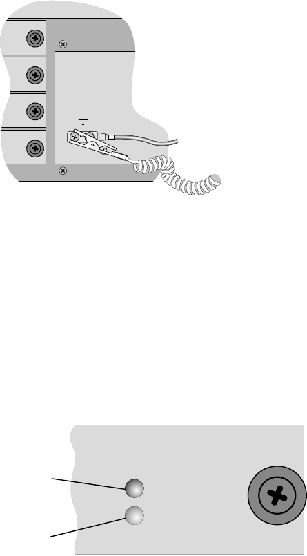
1027145–0001 Revision E Installing indoor hub equipment 6–31Hub installation
2. Wrap the ESD strap snugly around your wrist and connect
the alligator clip to one of the ground terminals on the front
of the IDU chassis power supply.
T0006053
3. Remove the SSI from its ESD protective packaging.
Retain the packaging in case it is necessary to return the
SSI for repair.
4. Slide the SSI into the guides on each side of the chassis SSI
slot and push it firmly into place until the front of the SSI is
flush with the front of the IDU chassis.
5. When the SSI receives power through contact with the IDU
backplane, it automatically initiates startup diagnostics.
Watch the LEDs to see the diagnostic results:
OK
STATUS
ALARM
()Red
On
Flashing
: Hardware failure
:TDM bus
communication failure
()Green
On: Normal operation
or module startup
T0009035
6. Tighten the thumbscrews at each end of the SSI.
To tighten the thumbscrews, push them toward the IDU
chassis and turn them clockwise. To fully tighten the
thumbscrews, use a Phillips screwdriver.
7. Repeat steps 1 through 6 for each SSI.
8. If any SSI slots are empty, cover the slot with a blank panel.
(If you need additional blank panels, order HNS part
1026730–0001.)
This completes the IDU installation.
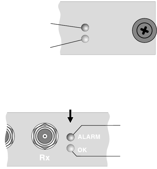
1027145–0001 Revision E 6–32 Installing indoor hub equipment Hub installation
LEDs on SSIs show:
•Module status (all SSIs)
•Link status (if applicable)
The subsections below show which LEDs are included on each
SSI and explain the meaning of the various LED on–off
conditions.
Module status LEDs
Included on: All SSIs
OK
STATUS
ALARM
()Red
On
Flashing
: Hardware failure
:TDM bus
communication failure
()Green
On: Normal operation
or module startup
T0009035
Link status LEDs
Included on: DS3–TDM, OC3c–ATM, and DS–3 transparent SSIs
T0006055
Link status LEDs
()Red
On: Alarm
()Green
On: Normal operation
SSI
SSI LEDs
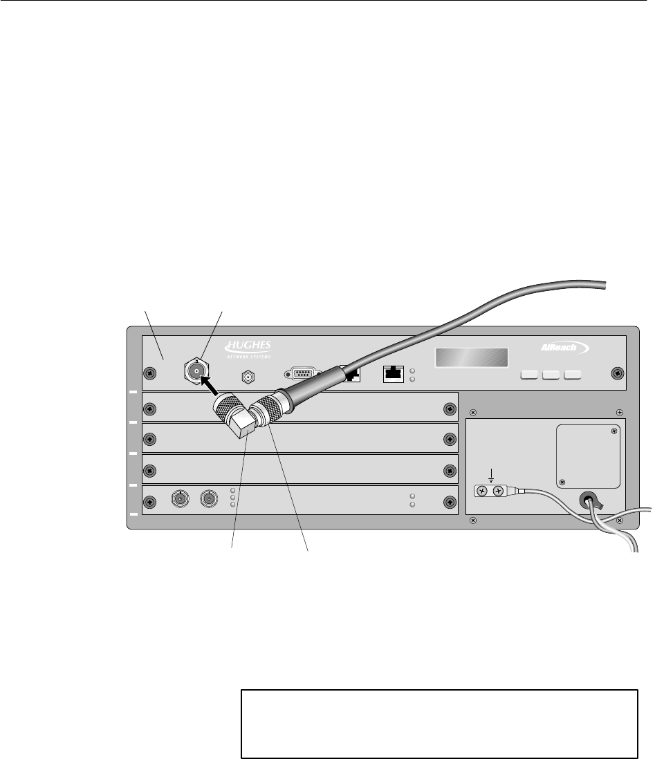
1027145–0001 Revision E Installing indoor hub equipment 6–33Hub installation
Connect the IFL cable to the CCM:
1. Make sure power to the IDU is off (or disconnected).
A label on the CCM front panel advises:
CAUTION: POWER DOWN
ODU BEFORE CONNECTING
OR DISCONNECTING IF
Removing power from the IDU powers down the ODU.
Make sure the IDU is powered off before you connect or
disconnect the IFL cable.
2. Using a 90° adapter, connect the IFL to the CCM IFL
interface, as shown in figure 6-21.
Figure 6-21 Connecting the IFL cable
T0006041
CCM
IDU
IFL
interface
1
2
3
4
5
TM
BROADBAND
HUB CCM
N connector
90 adapter°
IFL
ENTERPREVNEXT
For each IDU to be installed, repeat all applicable steps
in sections 6.2 through 6.6 (pages 6–7 through 6–33).
6.6
Connecting the IFL
to the CCM
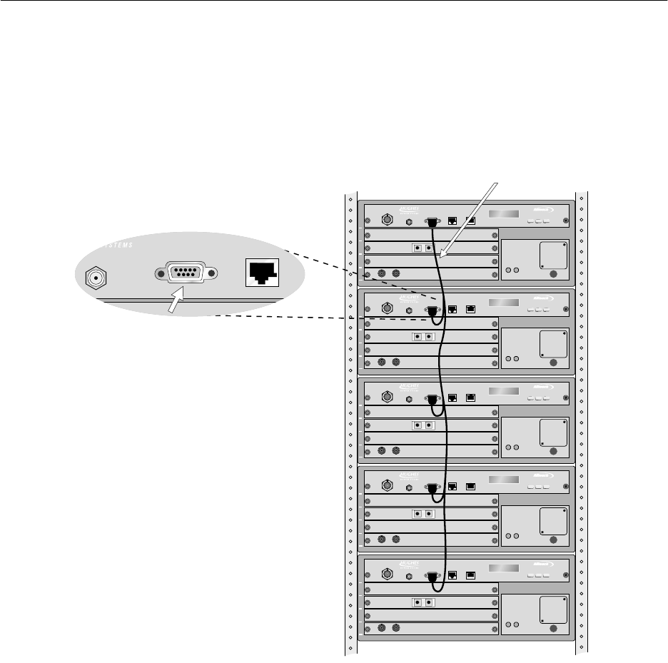
1027145–0001 Revision E 6–34 Installing indoor hub equipment Hub installation
If a backup HT has been installed, a CCM redundancy bus cable
(HNS 1028130–0001) must be installed, as shown in figure 6-22.
This cable connects up to five IDUs. It is used for HT IDUs only.
Connect the cable from (DB–9) maintenance port to maintenance
port, as shown in figure 6-22. If the IDUs cannot be installed close
enough to each other to connect the cable, an extender cable is
available.
Figure 6-22 HT IDUs connected by CCM redundancy bus cable
T0006030
1
2
3
4
5
TM
BROADBAND
1
2
3
4
5
TM
BROADBAND
1
2
3
4
5
TM
BROADBAND
1
2
3
4
5
TM
BROADBAND
1
2
3
4
5
TM
BROADBAND
CCM maintenance port
(DB-9 connector)
IDUs in rack
CCM redundancy bus cable
6.7
Redundancy bus
cable
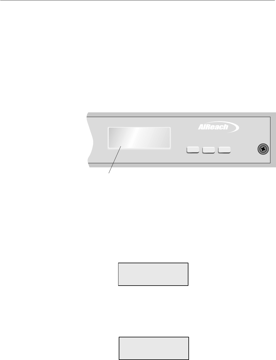
1027145–0001 Revision E Installing indoor hub equipment 6–35Hub installation
The text display (LCD) on the CCM front panel (figure 6-23):
•Shows CCM startup diagnostics (SUDS) tests as they occur
•Shows the system boot up sequence
•Shows the software loading sequence
•Indicates the status and operational state of system
components
•Provides functions necessary for commissioning the HT
You will use the LCD (liquid crystal display) and buttons on the
CCM front panel to conduct the test and checks described in
sections 6.9 and 7.3.
T0006042
LCD
TM
BROADBAND
ENTER
Main Menu
Status
PREVNEXT
Figure 6-23 CCM front panel LCD
When the CCM/ IDU is powered up or reset:
•SUDS run automatically.
•When SUDS are completed, the CCM LCD displays a
SUDS Completed message.
•The LCD then displays:
Initializing
Press Enter for Menu
To access the CCM LCD Main Menu, press the ENTER button on
the CCM front panel while the Initializing screen is displayed.
This puts the IDU into diagnostic mode. The LCD shows the Main
Menu:
Main Menu
Status
Note: After the CCM downloads its software and is operational,
you can access the Main Menu by pressing Enter.
6.8
Front panel LCD
operation
Accessing the LCD
Main Menu
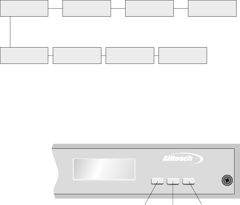
1027145–0001 Revision E 6–36 Installing indoor hub equipment Hub installation
The menu map below (figure 6-24) shows the available menu
options for HTs.
Note: Menu options are not the same for RTs and HTs.
Figure 6-24 LCD menu map for CCM HT
T0006025
Main Menu
Status Main Menu
MAC Main Menu
ESN Main Menu
Exit
Status menu
Status
CCM Status
ODU
Status
SSI n
SSI 1 - SSI 4
Status
Exit
Exits to
Main Menu
The CCM button functions are explained in figure 6-25:
TM
BROADBAND
Main Menu
Status
ENTER
PREVNEXT
T0009050
Scroll to
next menu
option
Scroll to
previous
menu option
Select
(Selects currently
displayed option
or menu)
Figure 6-25 CCM front panel button functions
Exit options
If you select Exit from the Main Menu . . .
. . . while the system is operating, it remains in
operational mode.
. . . when the system is not in operational mode, the
CCM reboots.
If you select Exit from the Status menu, the display returns to the
Main Menu.
LCD menu map
CCM button functions
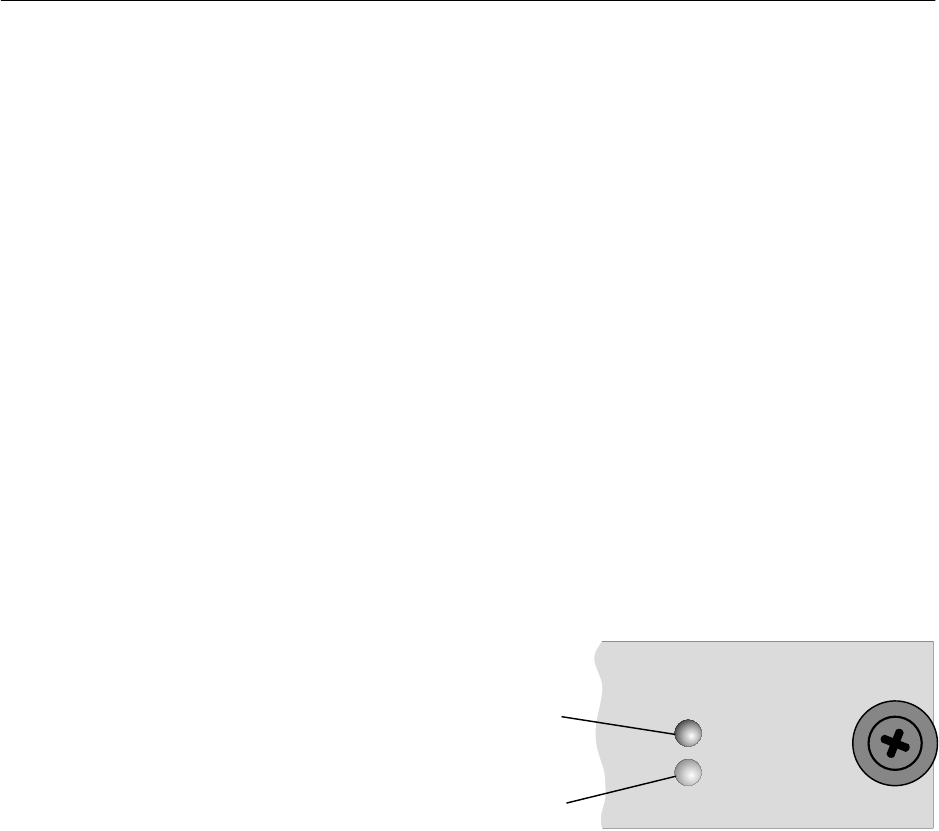
1027145–0001 Revision E Installing indoor hub equipment 6–37Hub installation
To prepare to commission the HT (chapter 7), you:
•Perform a CCM power–on test (this section)
•Check the status of each main component (section 7.3)
The objective is to verify that the equipment is operational before
commissioning. If you find a problem, you can correct it prior to
commissioning so it will not delay the commissioning process.
Before you conduct the power–on test, make sure all AIReach
Broadband equipment is properly connected.
1. Check these connections, with power to the IDU off:
•IDU to ODU (IFL from IDU to lightning arrestor
and from lightning arrestor to ODU)
•ODU ground connections
•IDU ground connections (if required)
Test the CCM for proper operation, as follows:
1. Apply power to the IDU chassis.
2. Observe the LEDs on the CCM front panel:
OK
STATUS
ALARM
()Red
On: Hardware failure
()Green
On: Normal operation
or CCM startup
T0009052
6.9
CCM power–on test
Check connections
CCM power–on test
(SUDS)

1027145–0001 Revision E 6–38 Installing indoor hub equipment Hub installation
3. Also observe the CCM startup diagnostics (SUDS) on the
CCM’s front panel LCD:
(For the tests and status checks described in this chapter, the
HT does not have to be connected to the EMS.)
SUDS start on powerup. While they run, the CCM front
panel shows the following messages, in the sequence
shown.
Equipment function is normal when you see the
messages shown below and no failure messages.
Initial powerup
SUDS CPU Reg OK
SUDS DRAM OK
CPU registers and dynamic
RAM are tested.
Timer test
SUDS Timer Test Timers are tested.
Watchdog timer test
SUDS WDT Test The watch dog timer
is tested.
PCI test
SUDS PCI Test The PCI controller is tested.
Static dual port RAM test
SUDS SDPRAM Test Static dual port RAM is tested.
Serial port 1 test
SUDS Ser 1 Test Serial port 1 is tested.
1027145–0001 Revision E Installing indoor hub equipment 6–39Hub installation
Serial port 2 test
SUDS Ser 2 Test Serial port 2 is tested.
LAN ID test
SUDS LAN ID Test LAN PCI registers are
configured and the LAN ID
is read from the LAN
controller.
Successful test completion
This message indicates that startup diagnostics have
successfully completed:
SUDS Completed
Failure indication
If a failure occurs during any of the tests listed above,
the LCD message sequence stops. The LCD shows the test
that failed on the first line and FAILED (flashing) on the
second line, as in the example below.
SUDS Ser 2 Test
FAILED
This screen indicates that
serial port 2 failed
diagnostics.
The LCD remains inactive unless you power the CCM off,
then on. This restarts SUDS.
If any CCM component fails, replace the CCM.
After SUDS are complete, the LCD displays the CCM boot
up sequence. At this point, you only need to verify that
SUDS have completed.
The AIReach Broadband hub LAN uses a Cisco 2611 (DC)
modular router and a Cisco 1924 (DC) Ethernet hub switch, which
connects to the router.
For installation and configuration information, refer to the Cisco
documentation. (The router must be configured for EMS–hub
communication.)
For detailed specifications, see the Hub and Remote Terminal Site
Preparation Guide or the Cisco documentation.
6.10
Hub LAN router and
LAN hub

HUB INSTALLATION
1027145–0001 Revision E Commissioning HTs 7–1Hub installation
Chapter 7
Commissioning HTs
This chapter includes:
•Prerequisites for commissioning – page 7–2
•HT commissioning procedure – page 7–3
•Checking component status – page 7–7
•HT to RT connection tests – page 7–11
Commissioning refers to verification procedures to ensure that the
newly installed hub terminal (HT) is operational.
Note: Most references in this chapter are to an HT. A hub may
consist of one HT but usually consists of multiple HTs. Each
HT—an ODU, IFL, and IDU—must be commissioned separately.

1027145–0001 Revision E 7–2 Commissioning HTs Hub installation
To ensure successful commissioning, you must verify that the
prerequisites listed below have been accomplished. These tasks
must all be completed prior to commissioning. If any of them has
not been done, make sure they are completed before you proceed
with commissioning.
The HT ODU, IFL, and IDU must be installed and
connected.
The Element Management System (EMS) hardware and
software must be installed and operational.
All physical LAN connections between the HT and EMS
must be completed and operational.
If the EMS is remote from the HT, the entire end–to–end link
must be verified as operational. The EMS must be able to
ping the hub LAN router and the specific port to be
connected to the HT.
The EMS database must be loaded and operational.
The EMS operator has to enter the HT MAC address and
configure the HT in the EMS database.
(The HT MAC address is printed on a tag attached to the
CCM and can also be read from the CCM LCD—from the
Main Menu MAC display.)
The CCM must be installed in the IDU. (SSIs are not
required for commissioning.)
Configure EMS and hub routers for EMS–hub
communication.
The hub router boot relay agent must be configured to
forward boot requests from the HT to the EMS.
If a backup HT has been installed, a CCM redundancy bus
cable must be connected.
7.1
Prerequisites for
commissioning
1027145–0001 Revision E Commissioning HTs 7–3Hub installation
To commission the HT, you apply power and observe the CCM
LCD while the HT downloads software and configuration data
from the EMS. This verifies that the HT equipment is operational.
(However, the HT is not ready for service until SSIs have been
configured by the EMS operator.)
To observe software and configuration downloading, you power
up the IDU and observe the LCD on the CCM front panel. The
CCM displays the following sequences:
•Startup diagnostics (SUDS)
•Boot up
•Software loading
•Configuration loading
After configuration loading, the LCD shows this message:
HT Freq 1A1
Disabled
(Frequency is specific to HT)
This display signals that downloading has completed, which
demonstrates that the equipment is operational. The HT is disabled
until SSIs are installed and configured (through the EMS).
When SSIs are installed and configured, the operational status is
HT Enabled.
7.2
HT commissioning
procedure
Summary
1027145–0001 Revision E 7–4 Commissioning HTs Hub installation
Startup diagnostics (SUDS) begin when the CCM is first powered
up. SUDS test the CCM’s components individually
1. Apply power to the IDU/ CCM, and observe the SUDS
sequence on the LCD:
For test identification details, see chapter 6, section 6.9.
SUDS Timer Test
SUDS WDT Test
SUDS PCI Test
SUDS SDPRAM Test
SUDS Ser 1 Test
SUDS Ser 2 Test
SUDS LAN ID Test
SUDS CPU Reg OK
SUDS DRAM OK
If all diagnostics complete successfully, the SUDS
sequence ends with a SUDS Completed message, as
shown below. If a test fails, the specific test that fails is
shown with a FAILED message, as shown below.
SUDS Completed SUDS Ser 2 Test
FAILED
or
The LCD remains inactive unless you power the CCM off,
then on. This restarts SUDS.
If any CCM component fails, replace the CCM.
Startup diagnostics
(SUDS) sequence
1027145–0001 Revision E Commissioning HTs 7–5Hub installation
After successful completion of startup diagnostics, the CCM
begins the boot up sequence. A CCM restart (or soft
reboot—without loss of power) also initiates boot up.
2. Observe the boot up sequence:
Hardware Initialization
Initializing The CCM hardware
components are initialized.
Several devices are initialized. If the baseband signal
processor (BSP) is unable to initialize the device, the
hardware is reset and another attempt to initialize occurs. If
a device fails to initialize, it is reported on the second line of
the LCD—for example:
Initializing
PLX Failed
The devices that are checked for initialization are listed
below. In the event of failure, any of these devices could
appear on the second line of the LCD (with “Failed”).
Device name on LCD Device
Host Cfg Vrc4375 PCI controller
PLX PLX9050
PLX IO PLX IO devices
LAN LAN controller
RCC FPGA RCC FPGA
BSB FPGA Baseband FPGA
QPIG FPGA QPIG FPGA
Tim Syn Timing synthesizer
If any CCM component fails, replace the CCM.
Sending Boot Request
Boot Boot request is being sent to
BOOTP server.
If the CCM does not receive a Boot Reply message, the
boot up sequence restarts (with hardware initialization). If,
for example, the EMS is not operational (and therefore no
Boot Reply message can be sent), the CCM will not
progress beyond the Boot display shown above.
Boot up sequence
1027145–0001 Revision E 7–6 Commissioning HTs Hub installation
When the CCM receives a boot reply message from the EMS boot
server, it begins to load its operational software.
3. Observe the Loading Software message on the LCD:
Loading Software
If the CCM is unable to load its software, the LCD returns
to the boot up sequence.
After loading its software, the CCM loads its configuration data.
After loading its configuration information, the CCM becomes
operational. This is indicated by HT Disabled on the LCD.
4. Watch for HT Disabled on the LCD:
HT Freq 1A1
Disabled
(Frequency is
specific to HT)
This display signals that downloading has completed,
which demonstrates that the equipment is operational.
The HT is disabled, but operational, until SSIs are installed
and configured (through the EMS). When SSIs are installed
and configured, the HT is ready for service, and the
operational status is HT Enabled.
The possible operational states are:
Enabled HT is ready for service.
Disabled Equipment is operational, but HT
is not ready for service.
Degraded One or more components is not
fully operational.
Enabled
Degraded HT is ready for service, but one
or more components is not fully
operational.
Enabled
In Test All of the HT’s SSI are in test
mode.
Software loading
Configuration loading
Operational state
1027145–0001 Revision E Commissioning HTs 7–7Hub installation
Use the LCD Status option to check the status of the CCM, SSIs,
and ODU, as explained in the following sections.
Check the CCM status as follows:
1. Press Enter on the CCM front panel.
The LCD shows:
Main Menu
Status
2. Press Enter, to go to (select) the Status menu:
Status
CCM
3. Press Enter to show the CCM status:
CCM
OK
The possible status conditions for CCMs, SSIs, and the
ODU are:
OK The component is operational.
Degraded The component is not fully operational.
Failed The component has failed.
Unknown The CCM cannot communicate with the
component.
Action for “Failed” or “Degraded”status
If the LCD shows Failed for any component, replace the
component.
If you see Degraded during installation, replace the
component. However, if you see Degraded while the
system is operation, under some circumstances you may not
need to replace the component (for example, if a failed port
is not needed).
7.3
Checking
component status
Check CCM status

1027145–0001 Revision E 7–8 Commissioning HTs Hub installation
Check the status of the installed SSIs as follows:
(Note that SSIs are not required for commissioning. They can be
installed after HT commissioning.)
1. From the Status / CCM display, shown below,
Status
CCM
press the NEXT button to scroll to the SSI status menu:
Status
SSI 2
2. Press NEXT or PREV to scroll to the SSI you want to
check:
Status
SSI 3
Note: SSIs are numbered SSI 1 through SSI 4, according to
their positions in the IDU chassis:
Chassis slot SSI number
2 1
3 2
4 3
5 4
Slot 1 is occupied by the CCM.
3. Press Enter to show the status of the selected SSI:
SSI 3
OK
The possible status conditions for SSIs are:
OK
Degraded
Failed
Unknown
(as explained on page 7–7)
Check the status of each installed SSI.
Check SSI status

1027145–0001 Revision E Commissioning HTs 7–9Hub installation
Check the status of the ODU as follows:
1. From the Status / SSI 1 display, shown below,
Status
SSI 1
press the NEXT button to scroll to the ODU status menu:
Status
ODU
2. Press Enter to show the ODU status:
ODU
OK
The possible status conditions for the ODU are:
OK
Degraded
Failed
Unknown
(as explained on page 7–7)
Note: You will not see ODU status information if the ODU
is not connected (via the IFL) to the IDU. The status will be
Unknown.
If a failure is indicated for any component, replace the failed
component. Run SUDS, and check the status of the new
component.
3. Exit the Status menu: Scroll to:
Status
Exit
and then press ENTER.
4. Exit the Main Menu: Scroll to:
Main Menu
Exit
and then press ENTER.
Check ODU status
1027145–0001 Revision E 7–10 Commissioning HTs Hub installation
At this point, HT commissioning is complete, except for the HT to
RT tests described in section 7.4. You may or may not be able to
complete these tests, depending on whether or not other network
components are installed and operational. (See the test
requirements listed in section 7.4.)
Leave the HT powered on for testing and operation.
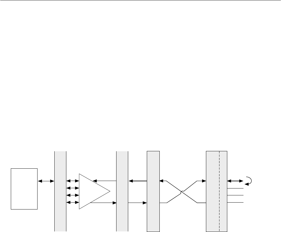
1027145–0001 Revision E Commissioning HTs 7–11Hub installation
Perform the applicable tests described below if the newly installed
HT meets the listed requirements. If the HT does not yet meet
these requirements, perform the tests at a later time.
This test verifies the DS1 connection from the HT to the RT.
Requirements
The DS1 test described below requires the following:
•The HT must be operational and in contact with the EMS.
•The RT must be fully installed, commissioned, and in
contact with the EMS through the hub.
•DS1 services must be configured and provisioned.
•There must be no alarms present at the RT location.
•A loopback connector must be connected to the input/out
port connector of the RT SSI used for the test, as illustrated
in figure 7-1.
Figure 7-1 HT to RT connection test setup
T0006029
DS3
mux
Bit error
rate test
set
P
a
t
c
h
p
a
n
e
l
HT RT
P
a
t
c
h
p
a
n
e
l
Loopback
connector
QRSS (2E20-1
pseudo-random)
test pattern
DS1 DS3 DS3 Over the air
interface
DS1
Hub site
Customer premises
Test procedure
1. Connect a DS1 test set to the out/input points at the patch
panel.
2. Select:
- QRSS (quasi random signal source) test pattern
- Recovered clock
- DS1 interface
3. Run the test for 1 hour.
Results
The HT passes if there are no errors and no clock or frame slips
during the test.
Record the results on the form on the following page (or make a
photocopy).
7.4
HT to RT connection
tests
DS1 test
1027145–0001 Revision E 7–12 Commissioning HTs Hub installation
HT to RT DS1 test results
HT location: ____________________________________________
Test successful? ___ Yes ___ No RSSI __________
If not successful, complete:
Bit error rate _______________ Frame slips _______________
Frame errors _______________ Clock slips ________________
Trouble report generated? ___ Yes ___ No
If yes, report number: ____________________
If applicable: Faulty module part number ______________________
Serial number _____________________
If applicable: Replacement board part number __________________
Serial number______________________
BER test printout attached? ___ Yes ___ No
Comments:
_________________________________________________________________________________
_________________________________________________________________________________
Tested by (print name and sign): _______________________________________________________
Customer (print name and sign): ________________________________________________________
Date __________________________
1027145–0001 Revision E Commissioning HTs 7–13Hub installation
This test verifies the DS3 connection from the HT to the RT.
Requirements
The DS3 test described below requires the following:
•The HT must be operational and in contact with the EMS.
•The RT must be fully installed, commissioned, and in
contact with the EMS through the hub.
•DS3 services must be configured and provisioned.
•There must be no alarms present at the RT location.
•A loopback connector must be connected to the input/out
port connector of the RT Universal DS1 SSI used for the
test. (See figure 7-1.)
Test procedure
1. Connect a DS3 test set to the out/input points at the patch
panel.
2. Select:
- C bit framing
- Recovered clock
- DS3 interface
DS1 services may be dropped from the DS3 data stream and
tested using QRSS test patten.
The DS3 test set and HT may be timed from the same
source.
3. Run the test for 1 hour.
Results
The HT passes if there are no errors and no clock or frame slips
during the test.
Record the results on the form on the following page (or make a
photocopy).
DS3 test
1027145–0001 Revision E 7–14 Commissioning HTs Hub installation
HT to RT DS3 test results
HT location: ____________________________________________
Test successful? ___ Yes ___ No RSSI __________
If not successful, complete:
Bit error rate _______________ Frame slips _______________
Frame errors _______________ Clock slips ________________
Trouble report generated? ___ Yes ___ No
If yes, report number: ____________________
If applicable: Faulty module part number ______________________
Serial number _____________________
If applicable: Replacement board part number __________________
Serial number______________________
BER test printout attached? ___ Yes ___ No
Comments:
_________________________________________________________________________________
_________________________________________________________________________________
Tested by (print name and sign): _______________________________________________________
Customer (print name and sign): ________________________________________________________
Date __________________________
1027145–0001 Revision E Commissioning HTs 7–15Hub installation
This test verifies the fractional DS1 connection from the HT to the
RT.
Requirements
The fractional DS1 test described below requires the following:
•The HT must be operational and in contact with the EMS.
•The RT must be fully installed, commissioned, and in
contact with the EMS through the hub.
•DS3/DS1, fractional DS0 services must be configured and
provisioned.
•There must be no alarms present at the RT location.
•A loopback connector must be connected to the input/out
port connector on the RT DS1 SSI used for the test. (See
figure 7-1.)
Test procedure
1. Connect a DS3 test set to the out/input points at the patch
panel.
2. Select:
- C bit framing
- Recovered clock
- DS3 interface
- QRSS test patten
The fractional DS1 services may be dropped and tested after
connecting a DS1/DS0 test set to the input/output ports of
the DS3 test set.
The DS3 test set and HT may be timed from the same
source.
3. Run the test for 1 hour.
Results
The HT passes if there are no errors and no clock or frame slips
during the test.
Record the results on the form on the following page (or make a
photocopy).
Fractional DS1 test
1027145–0001 Revision E 7–16 Commissioning HTs Hub installation
HT to RT fractional DS1 test results
HT location: ____________________________________________
Number of DS0s tested _______
Test successful? ___ Yes ___ No RSSI __________
If not successful, complete:
Bit error rate _______________ Frame slips _______________
Frame errors _______________ Clock slips ________________
Trouble report generated? ___ Yes ___ No
If yes, report number: ____________________
If applicable: Faulty module part number ______________________
Serial number _____________________
If applicable: Replacement board part number __________________
Serial number______________________
BER test printout attached? ___ Yes ___ No
Comments:
_________________________________________________________________________________
_________________________________________________________________________________
Tested by (print name and sign): _______________________________________________________
Customer (print name and sign): ________________________________________________________
Date __________________________
1027145–0001 Revision E Commissioning HTs 7–17Hub installation
This test verifies the fractional DS3 connection from the HT to the
RT.
Requirements
The fractional DS3 test described below requires the following:
•The HT must be operational and in contact with the EMS.
•The RT must be fully installed, commissioned, and in
contact with the EMS through the hub.
•Fractional DS3 services must be configured and
provisioned.
•There must be no alarms present at the RT location.
•A loopback connector must be connected to the input/out
port of the RT DS3 SSI used for the test. (See figure 7-1.)
Test procedure
1. Connect a DS3 test set to the out/input points at the patch
panel.
2. Select:
- C bit framing
- Recovered clock
- DS3 interface
Fractional DS1 services may be dropped from the DS3 data
stream and tested using QRSS test pattern.
The DS3 test set and HT may be timed from the same
source.
3. Run the test for 1 hour.
Results
The HT passes if there are no errors and no clock or frame slips
during the test.
Record the results on the form on the following page (or make a
photocopy).
Fractional DS3 test
1027145–0001 Revision E 7–18 Commissioning HTs Hub installation
HT to RT fractional DS3 test results
HT location: ____________________________________________
Number of DS1s tested ______
Test successful? ___ Yes ___ No RSSI __________
If not successful, complete:
Bit error rate _______________ Frame slips _______________
Frame errors _______________ Clock slips ________________
Trouble report generated? ___ Yes ___ No
If yes, report number: ____________________
If applicable: Faulty module part number ______________________
Serial number _____________________
If applicable: Replacement board part number __________________
Serial number______________________
BER test printout attached? ___ Yes ___ No
Comments:
_________________________________________________________________________________
_________________________________________________________________________________
Tested by (print name and sign): _______________________________________________________
Customer (print name and sign): ________________________________________________________
Date __________________________
HUB INSTALLATION
1027145–0001 Revision E Final steps 8–1
Hub installation
Chapter 8
Final steps
This chapter describes the final steps you take before leaving the
customer site after completing the installation:
•Weatherproofing – page 8–2
•Inspection, cleanup, and customer sign–off – page 8–3
•Connecting customer equipment – page 8–3
Observe these safety warnings while performing final inspections
and related tasks:
DANGER
Do not work on a ladder or roof without
first reading the safety warnings on page x
of this manual. Failure to observe these
warnings could result in personal injury or
death.
WARNING
Potential radio frequency (RF) hazard:
•Keep away from the front of the
outdoor unit (ODU) antenna while the
ODU is operating. Note that you cannot
tell from outward appearance whether
the ODU is operating or not.
•Be careful with respect to the ODU you
are installing and ODUs that may
already be operating in the installation
area.
Failure to observe these warnings could
result in injury to eyes or other personal
injury.
Safety warnings
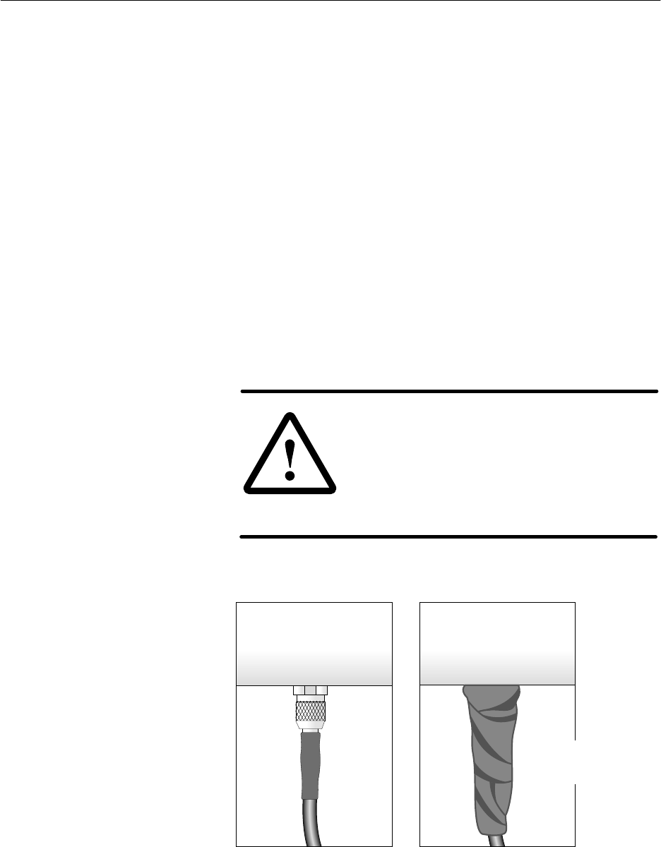
1027145–0001 Revision E 8–2 Final steps Hub installation
After the HT has been successfully commissioned, seal all outdoor
IFL connections (including connections to the lightning arrestor
assembly) with electrical tape and weatherproofing compound to
protect against moisture penetration:
See figure 8-1.
1. Starting at the connector end, wrap electrical tape around
the connector and part of the cable.
2. Cover the electrical tape with weatherproofing compound,
and work the compound into all joints and cracks where
water could enter.
3. Smooth the weatherproofing compound, giving the
connection a tapered appearance, as shown in figure 8-1.
4. Again starting at the connector end, wrap a second layer of
electrical tape around (on top of) the weatherproofing
compound.
5. Press the tape into the weatherproofing compound.
The resulting seal should be tight and compact, with no
loose tape ends.
CAUTION
Outdoor connectors are subject to
moisture contamination. Even minute
amounts of water vapor can condense
and cause a short circuit. Thoroughly
seal all outdoor IFL connections with
weatherproofing compound.
Figure 8-1 Applying weatherproofing compound and tape
Before weatherproofing After weatherproofing
Heat
shrink Weatherproofing
compound and tape
T0006027
8.1
Weatherproofing

1027145–0001 Revision E Final steps 8–3
Hub installation
After all equipment is installed and commissioned, visit each
installation area to inspect the equipment and make sure the area is
left clean and orderly.
Inspect all equipment to make sure:
•All cables are dressed (as necessary) and not bent
excessively.
•All connections are secure.
•IFL connections and entry panels are properly
waterproofed.
•IDUs, racks, and ODUs are properly grounded.
•Antenna mount bolts are tightened.
•ODU adjusters and the temporary installation collar have
been removed for future use.
Clean up all installation areas:
•Make sure no tools or other objects are left on or near the
equipment.
•Remove or neatly store any excess materials.
•Remove all debris.
Before leaving the site, notify the appropriate customer
representative that the work has been completed. Ask the
representative to sign the work order, indicating that the
equipment has been installed and has passed the initial loopback
verification test(s).
The customer is responsible for connecting customer equipment to
the AIReach Broadband equipment through connections to
service–specific interface (SSI) modules. Refer to section 6.5 for
information on the services and specific interfaces provided by
each SSI type.
8.2
Inspection, cleanup,
and sign–off
Inspection
Cleanup
Customer sign–off
8.3
Connecting
customer
equipment

HUB INSTALLATION
1027145–0001 Revision E Troubleshooting 9–1Hub installation
Chapter 9
Troubleshooting
This chapter includes:
•Troubleshooting flow charts – page 9–1
•Service information – page 9–6
The troubleshooting flow charts in this chapter will help isolate
most problems you might encounter during installation and
operation of the AIReach Broadband system.
Each flow chart begins with a specific problem, then leads you to
specific corrective actions you should take. Where actions are
numbered in these charts, you many not need to perform all of
the actions. Perform the actions in order, and check after each
action to see if the problem has been resolved. Proceed to the
next action only if the previous action did not correct the
problem.
The information in this chapter is intended for use by technicians
experienced in electronics troubleshooting. Therefore, it suggests
corrective actions but does not include detailed instructions for
each action.
9.1
Troubleshooting
flow charts
1027145–0001 Revision E 9–2 Troubleshooting Hub installation
Troubleshooting the CCM
CCM will not
power up.
Is the correct
voltage present at
the IDU chassis
input?
Does chassis
cooling fan operate
when power is
applied?
Check power
source.
Replace CCM.
Replace
IDU chassis.
Yes
Yes
No
No
hb109
Problem:
1027145–0001 Revision E Troubleshooting 9–3Hub installation
CCM failed startup
diagnostics (SUDS).
Replace CCM.
Problem:
During CCM bootup / hardware
initialization, LCD displays any of
the following messages, indicating
a device failure:
Host Cfg Failed
PLX Failed
PLX IO Failed
LAN Failed
RCC FPGA Failed
BSB FPGA Failed
QPIG FPGA Failed
Tim syn Failed
Replace CCM.
hb110
Problem:
Troubleshooting the CCM -
Continued
1027145–0001 Revision E 9–4 Troubleshooting Hub installation
Can the EMS
operator ping the
router nearest to
the hub?
1. Check the cable from the router
and LAN hub to the CCM.
2. Check the CCM MAC address in
the EMS database accessible at
the CCM.
3. Check the routing information in
the EMS database.
4. Replace the CCM.
Ask network manager
to check network
rou in tables.tg
Yes
No
hb111
EMS cannot communicate
with HT CCM.
Problem:
Troubleshooting the hub site LAN connection
1027145–0001 Revision E Troubleshooting 9–5Hub installation
Hub site LAN connection -
Continued
Are Bootp
IP messages
reaching the
EMS?
1. Check IP address in the EMS
database.
2. Check HT MAC address.
1. Ping the nearest router.
(If no response, contact network
manager.)
2. Check LAN cable from the router
and LAN hub.
3. Replace the CCM.
Yes
No
hb112
HT does not download
software.
Problem:
1027145–0001 Revision E 9–6 Troubleshooting Hub installation
Are SSIs
installed and
configured?
"HT Disabled" message is
normal if SSIs have not been
installed and configured.
Yes
No
hb113
After CCM has downloaded
its software, CCM LCD shows
"HT Disabled" message.
Problem:
Troubleshooting: "HT Disabled"
If Status screen shows
"Degraded" or
"Unknown" for any
component . . .
Check CCM,
SSIs, and ODU
via CCM LCD
Status menu.
If Status screen shows
"CCM Failed" or
"SSI Failed" . . .
(number)
Refer to
section
If Status screen shows
"ODU Failed" . . .
Replace the
CCM or
indicated SSI.
1. Check IFL cable
for continuity.
2. Check IFL cable
connectors.
3. Replace ODU.
7.3.
IDU chassis fan doesn’t work. If the chassis is a dc powered unit,
make sure the polarity of the wires to the power supply is not
reversed.
If you find a faulty component, contact your contract administer to
arrange for repair or replacement.
9.2
Additional
troubleshooting
information
9.3
Repair or
replacement service

HUB INSTALLATION
1027145–0001 Revision E Maintenance 10–1Hub installation
Chapter 10
Maintenance
The AIReach Broadband physical system requires no routine
maintenance. However, to facilitate expansion, reconfiguration, or
repairs, you may need to add, move, or replace components. This
chapter includes instructions for:
•Adding or moving SSIs – page 10–2
•Replacing components – page 10–3
•Replacing the ODU – page 10–3
•Replacing the IDU chassis – page 10–8
•Replacing the CCM – page 10–10
•Replacing SSIs – page 10–11
•Replacing the IFL – page 10–12
•Dismantling an HT – page 10–14

1027145–0001 Revision E 10–2 Maintenance Hub installation
Notify the EMS operator before you add or move SSIs. Make
sure the EMS operator has performed any prerequisite steps that
may be necessary before you add or move an SSI.
For instructions on replacing SSIs, see section 10.6.
CAUTION
Always wear a new or recently tested
electrostatic discharge (ESD) wrist strap
(figure 6-16) when handling circuit
modules. Failure to use a wrist strap may
result in damage to components.
You can install additional SSIs while the system is powered on. To
add an SSI, follow the instructions in section 6.5 (page 6–28).
After installing an SSI, use the CCM LCD Status function to
check its operational status. The LCD should display OK. (For an
explanation of the CCM LCD Status function, see section 7.3.)
SSIs are hot–swappable, meaning you can move them from one
slot to another or to another chassis while the chassis are powered
on.
Important: Install the OC3c–ATM SSI in chassis slot 3 only,
and install the DS3–TDM SSI in slot 5 only.
To move an SSI:
1. Loosen the thumbscrews at each end of the SSI.
2. Using an ESD wrist strap connected to a chassis ground
terminal, slide the SSI out of its slot.
3. Move the SSI to its new location and insert it into the slot.
4. Tighten the thumbscrews at each end of the SSI.
5. Use the CCM LCD to check the SSI status. (For details, see
section 7.3).
10.1
Adding or moving
SSIs
Adding SSIs
Moving SSIs
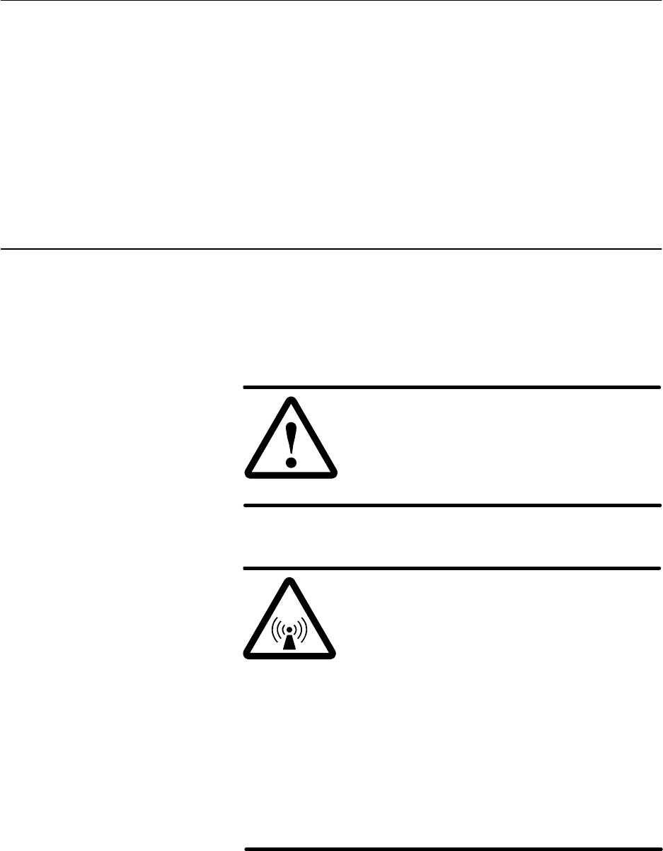
1027145–0001 Revision E Maintenance 10–3Hub installation
The following HT components can be replaced at the installation
site if a problem is attributed to the component:
•ODU
•IDU chassis
•CCM
•SSIs
•IFL
Specific instructions for replacing each component follow, in
sections 10.3 through 10.7.
If the ODU is faulty, you normally replace the transceiver only
(which contains the ODU electronics). Replace the antenna only if
it is physically damaged (for example, wind or water damage) or
has some other known problem.
DANGER
Do not work on a ladder or roof without
first reading the safety warnings on page x
of this manual. Failure to observe these
warnings could result in personal injury or
death.
WARNING
Potential radio frequency (RF) hazard:
•Keep away from the front of the
outdoor unit (ODU) antenna while the
ODU is operating. Note that you cannot
tell from outward appearance whether
the ODU is operating or not.
•Be careful with respect to the ODU you
are installing and ODUs that may
already be operating in the installation
area.
Failure to observe these warnings could
result in injury to eyes or other personal
injury.
10.2
Replacing
components
10.3
Replacing the ODU
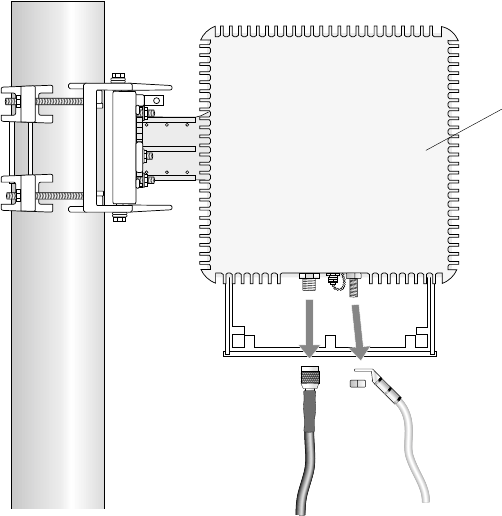
1027145–0001 Revision E 10–4 Maintenance Hub installation
To replace the transceiver, follow these steps:
Removing the existing transceiver
1. Make sure the EMS operator has taken the HT out of
service.
2. At the IDU location: Remove power from the IDU chassis
power supply.
3. On the roof: Disconnect the ground cable and IFL from the
ODU transceiver, as shown in figure 10-1.
Figure 10-1 Disconnecting the ODU
ground and IFL cables
Ground
Mast
T0006045
IFL
Transceiver
Rear
view
Replacing the
transceiver
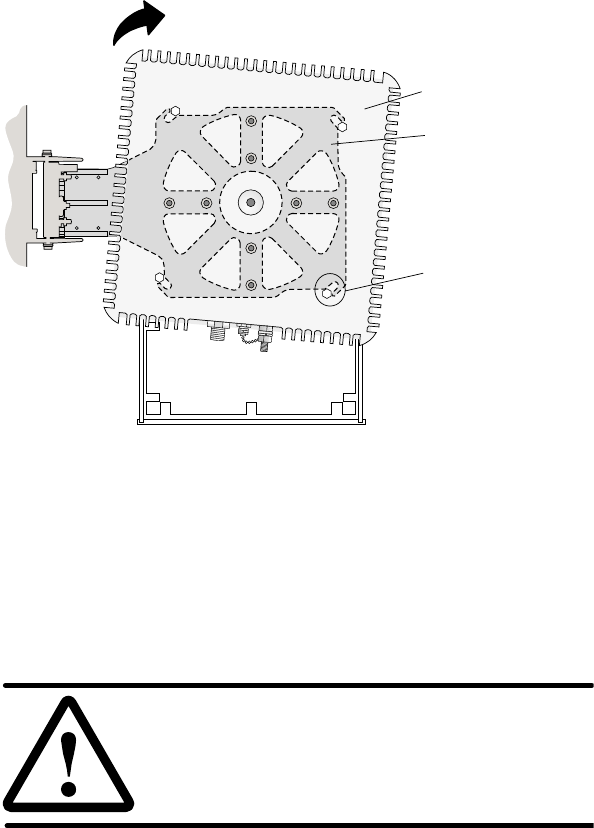
1027145–0001 Revision E Maintenance 10–5Hub installation
4. Loosen the four transceiver mounting bolts (shown in figure
10-2).
Transceiver
Groove and
mounting bolt.
(Bolts are attached
to transceiver.)
Antenna bracket
(between
transceiver)
antenna
and
Rotate transceiver to slide bolts out of grooves.
(Rotation direction depends on orientation
of antenna bracket to right or left.)
T0006044
Antenna
Some antenna
models may be
smaller than the
antenna shown
here.
Figure 10-2 Removing the transceiver
5. Rotate the transceiver until the bolts slide out of the four
grooves in the antenna bracket. (The direction of rotation
depends on the orientation of the antenna bracket—to the
right or left.) If the mounting bolts will not slide into the
grooves, loosen the bolts. See figure 10-2.
CAUTION
Do not allow dirt, dirt, moisture, or other
contaminants to enter the waveguide.
6. Cover the transceiver coupling (center hole) with a plastic
coupling plug (if available) or tape to prevent
contamination.
Installing the replacement transceiver
7. To install the replacement transceiver, follow the steps in
section 4.10 (page 4–23).
8. Connect the IFL cable to the IFL connector on the
transceiver.
9. Ground the ODU, as explained in section 4.11 (page 4–25).
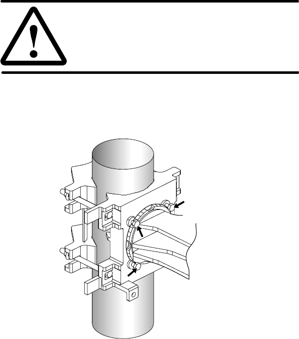
1027145–0001 Revision E 10–6 Maintenance Hub installation
10. After you replace the transceiver:
- Go to the next subsection (Replacing the antenna) only
if you need to replace the antenna.
- Apply power to the IDU chassis power supply.
- Use the CCM LCD to check the ODU status. (For
details, see section 7.3).
- Notify the EMS operator that the HT is ready to
resume service.
If you are replacing the transceiver only, you should not need to
realign the antenna.
If you need to replace the antenna, follow these steps:
Removing the existing antenna
1. Remove the transceiver (steps 1 through 6 above, beginning
on page 10–4). Be sure to remove power from the IDU
chassis power supply.
CAUTION
Do not allow dirt, dirt, moisture, or other
contaminants to enter the waveguide.
2. Loosen the four antenna bracket locking nuts.
Figure 10-3 Antenna bracket locking nuts
hb116
Antenna bracket
locking nuts
Antenna
mount
Antenna
bracket
Replacing the antenna
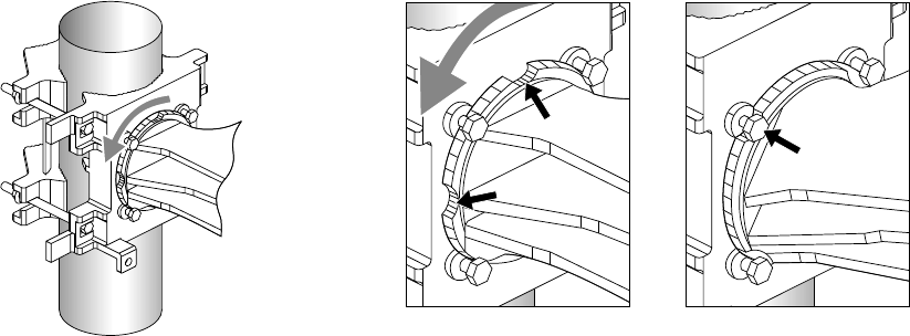
1027145–0001 Revision E Maintenance 10–7Hub installation
3. Rotate the antenna (clockwise or counterclockwise) until
the antenna bracket reliefs (curved indentations) are aligned
with the four nuts on the mast interface, as shown in figure
10-4.
Figure 10-4 Removing the antenna
hb117
Relief
Relief
Reliefs not aligned
with nuts
Nut
Reliefs aligned with nuts
(Antenna in position
to be removed)
Rotate antenna and antenna bracket until
reliefs are aligned with the 4 antenna
bracket locking nuts, as show at right.
Antenna
mount
Antenna
bracket
4. Move the antenna away from the mast interface.
5. Cover the antenna waveguide (center hole) with a plastic
plug or tape to protect against contamination.
Installing the replacement antenna
6. Attach the replacement antenna to the mount, as explained
in section 4.6 (page 4–15).
7. Align the replacement antenna by adjusting the azimuth and
elevation as detailed in sections 4.7 and 4.8 (beginning on
page 4–18).
8. Attach the transceiver to the antenna, as explained in
section 4.10 (page 4–23).
9. Connect the IFL cable to the IFL connector on the
transceiver.
10. Ground the ODU, as explained in section 4.11 (page 4–25).
11. Apply power to the IDU chassis power supply (section 6.3,
page 6–11).
12. Use the CCM LCD to check the ODU status. (For details,
see section 7.3).
13. Notify the EMS operator that the HT is ready to resume
service.
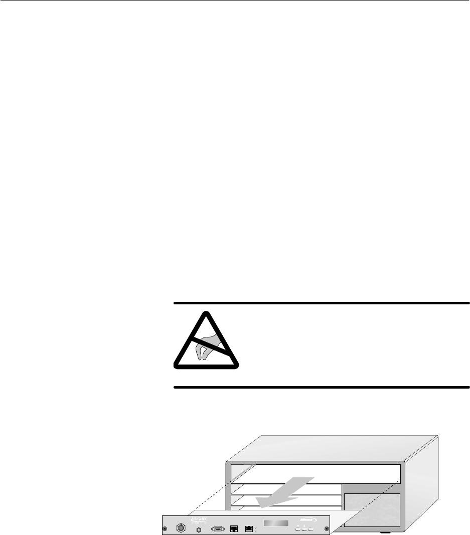
1027145–0001 Revision E 10–8 Maintenance Hub installation
Do not attempt to service or replace the IDU chassis power supply.
If there is a problem with the power supply, replace the entire
IDU chassis.
To replace the IDU chassis, follow these steps:
If you need additional details concerning the instructions below,
see chapter 6.
Removing the existing IDU chassis
1. Make sure the EMS operator has taken the HT out of
service.
2. Remove power from the IDU chassis power supply.
3. Mark each cable or otherwise note where each cable is
connected.
4. Remove all cables from all modules.
5. Remove the CCM:
a. Loosen the thumbscrews at each end.
b. Using an ESD wrist strap connected to a chassis
ground terminal, slide the CCM out of its slot, as
shown in figure 10-5.
CAUTION
Always wear a new or recently tested
electrostatic discharge (ESD) wrist strap
(figure 6-16) when handling circuit
modules. Failure to use a wrist strap may
result in damage to components.
Figure 10-5 Removing the CCM
hb118
TM
BROADBAND
ENTER
HUB CCM
10.4
Replacing the IDU
chassis
1027145–0001 Revision E Maintenance 10–9Hub installation
6. Place the CCM in its ESD protective packaging.
7. Remove all SSIs:
a. Using a piece of tape on the SSI front panel, mark the
slot number where each SSI was installed.
b. Loosen the thumbscrews at each end.
c. Using an ESD wrist strap connected to a chassis
ground terminal, slide the SSI out of its slot.
8. Place each SSI in ESD protective packaging.
9. If the IDU chassis is rack mounted, remove the four
mounting screws and remove the chassis from the rack.
10. Remove the rack mounting brackets from the chassis.
Installing the replacement IDU chassis
Refer to the instructions in chapter 6 to:
11. Install the replacement chassis in a rack, if the original
chassis was installed in a rack (section 6.2).
12. Re–connect power to the IDU chassis power supply (section
6.3).
13. Conduct a power–on test (section 6.3).
14. Re–install the CCM (section 6.4).
15. Re–install the SSIs (section 6.5).
Install each SSI in the slot it was in before. Refer to the slot
numbers you marked on the tape on each SSI.
16. Re–connect the IFL cable and all other cables to the CCM
and SSIs.
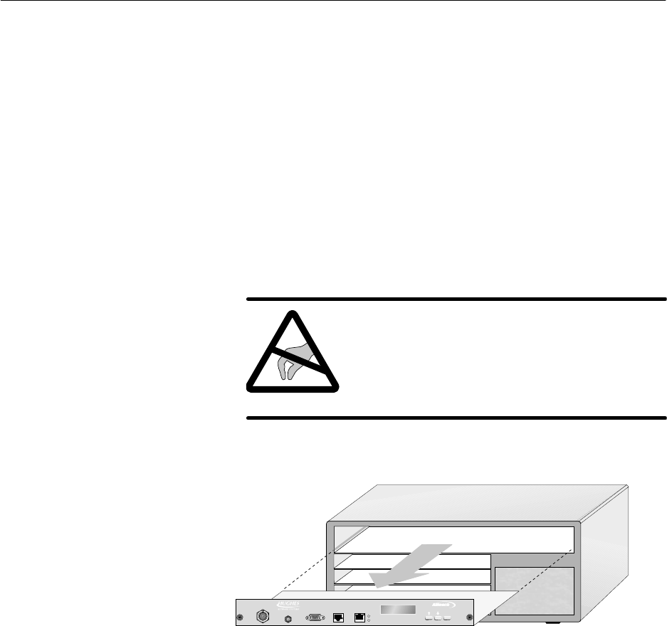
1027145–0001 Revision E 10–10 Maintenance Hub installation
If you need to replace the CCM, follow these steps:
If you need additional details concerning the instructions below,
see section 6.4 (page 6–26).
Removing the existing CCM
1. Make sure the EMS operator has taken the HT out of
service.
2. Remove power from the IDU chassis power supply.
3. Loosen the thumbscrews at each end of the (existing) CCM.
4. Using an ESD wrist strap connected to a chassis ground
terminal, slide the CCM out of its slot, as shown in
figure 10-6.
CAUTION
Always wear a new or recently tested
electrostatic discharge (ESD) wrist strap
(figure 6-16) when handling circuit
modules. Failure to use a wrist strap may
result in damage to components.
Figure 10-6 Removing the CCM
hb118
TM
BROADBAND
ENTER
HUB CCM
5. Place the CCM in ESD protective packaging.
Installing the replacement CCM
6. Slide the replacement CCM into the CCM slot (slot 1).
7. Tighten the thumbscrews at each end of the CCM.
8. Apply power to the IDU chassis power supply.
9. Use the CCM LCD to check the CCM status. (For details,
see section 7.3).
10. Notify the EMS operator that the HT is ready to resume
service.
10.5
Replacing the CCM
1027145–0001 Revision E Maintenance 10–11Hub installation
To replace an SSI, follow the steps below.
SSIs are hot swappable, so you do not need to power off the IDU
to replace an SSI. If you need additional details concerning the
instructions below, see section 6.5 (page 6–28).
Removing the SSI
1. Note which slot the SSI to be replaced is in.
2. Loosen the thumbscrews at each end of the SSI.
3. Using an ESD wrist strap connected to a chassis ground
terminal, slide the SSI out of its slot.
CAUTION
Always wear a new or recently tested
electrostatic discharge (ESD) wrist strap
(figure 6-16) when handling circuit
modules. Failure to use a wrist strap may
result in damage to components.
4. Place the SSI in ESD protective packaging.
Installing the replacement SSI
5. Slide the replacement SSI into the slot from which you
removed the previously installed SSI.
6. Tighten the thumbscrews at each end of the SSI.
7. Use the CCM LCD to check the SSI status. (For details, see
section 7.3).
8. Notify the EMS operator that the replacement SSI is ready
for service.
10.6
Replacing SSIs
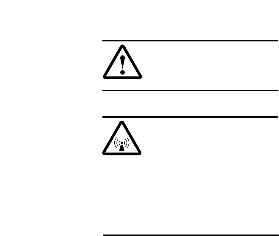
1027145–0001 Revision E 10–12 Maintenance Hub installation
If you suspect problems with the IFL, check all IFL connections
and then test the IFL. Replace the IFL only if there is a known
problem that cannot be corrected any other way.
DANGER
Do not work on a ladder or roof without
first reading the safety warnings on page x
of this manual. Failure to observe these
warnings could result in personal injury or
death.
WARNING
Potential radio frequency (RF) hazard:
•Keep away from the front of the
outdoor unit (ODU) antenna while the
ODU is operating. Note that you cannot
tell from outward appearance whether
the ODU is operating or not.
•Be careful with respect to the ODU you
are installing and ODUs that may
already be operating in the installation
area.
Failure to observe these warnings could
result in injury to eyes or other personal
injury.
10.7
Replacing the IFL
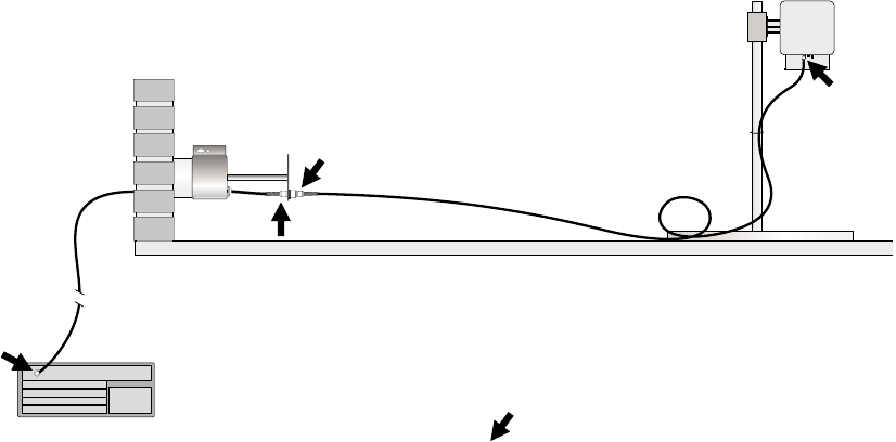
1027145–0001 Revision E Maintenance 10–13Hub installation
Environments where IFLs are installed vary widely. Therefore, use
the general instructions below as guidelines.
If you need to replace the IFL:
1. Make sure the EMS operator has taken the HT out of
service.
2. Remove power from the IDU chassis power supply.
3. Disconnect all four IFL N connectors, as shown in
figure 10-7:
- 1 connector at the IDU
- 1 connector at the ODU
- 2 connectors at the lightning arrestor
Figure 10-7 Disconnect N connectors at the
four locations shown here
ODU
IFL
Lightning
arrestor
T0006013
IFL
Roof
IDU
N
N
N
N
N= N connector location
4. Remove the two IFL cable segments:
- From IDU to the lightning arrestor
- From the lightning arrestor to the ODU
5. Install the replacement IFL cable according to the
instructions in chapter 5.
1027145–0001 Revision E 10–14 Maintenance Hub installation
If you need to dismantle an entire HT, follow the steps below.
DANGER
Do not work on a ladder or roof without
first reading the safety warnings on page x
of this manual. Failure to observe these
warnings could result in personal injury or
death.
WARNING
Potential radio frequency (RF) hazard:
•Keep away from the front of the
outdoor unit (ODU) antenna while the
ODU is operating. Note that you cannot
tell from outward appearance whether
the ODU is operating or not.
•Be careful with respect to the ODU you
are installing and ODUs that may
already be operating in the installation
area.
Failure to observe these warnings could
result in injury to eyes or other personal
injury.
Follow these steps:
1. Make sure the EMS operator has taken the HT out of
service.
2. Remove power from the IDU chassis power supply.
3. On the roof: Disconnect the IFL and ground cable from the
ODU. See section 10.3.
4. Remove the transceiver. See section 10.3.
5. Remove the antenna. See section 10.3.
6. Disassemble the mast and mast mount.
7. At the IDU location: Remove all cables from all modules.
If the cables will be reused, mark them to identify them.
8. Optional: Remove the CCM and SSIs from the chassis.
(Depending on what you will do with the equipment, you
might want to leave the CCM and SSIs installed.) See
sections 10.5 and 10.6.
9. Remove the IDU chassis.
10. Remove the IFL cable and lightning arrestor (unless the
lightning arrestor is being used for other HTs or will be
reused).
10.8
Dismantling an HT

1027145–0001 Revision E A- 1
Appendix A
Acronyms and abbreviations
ac – alternating current
ATM – asynchronous transfer mode
AW G – American wire gauge
BER – bit error rate
BSP – baseband signal processor
C – Celsius
CCM – channel and control module
cm – centimeter
CMR – communication riser
CPU – central processing unit
dc – direct current
DRAM – dynamic RAM
EIDU – expansion indoor unit
EMS – Element Management System
ESD – electrostatic discharge
ESN – electronic serial number
F – Fahrenheit
FCC – Federal Communications Commission
FRAD – frame relay access device
ft – foot
HNS – Hughes Network Systems
HT – hub terminal
Hz – hertz
ID – identification
IDU – indoor unit
IEC – International Electrotechnical Commission
IF – intermediate frequency
IFL – intrafacility link
in. – inch
IP – Internet protocol
LAN – local area network
lb – pound(s)
LCD – liquid crystal display
LED – light emitting diode
LOS – line of sight
m – meter
MAC – media access control
mm – millimeter
NEBS – Network Equipment Building Standards
NEC – National Electric Code
NEMA – National Electrical Manufacturing
Association
NFPA – National Fire Protection Association
ODU – outdoor unit
OSPF – open shortest path first
PC – personal computer
PCI – PC interface
PMP – point–to–multipoint
QRSS – quasi random signal source
RAM – random–access memory
RF – radio frequency
ROM – read–only memory
RT – remote terminal
SDRAM – static dual port RAM
SSI – service–specific interface
SUDS – startup diagnostics
TAC – Technical Assisance Center
TDM – time division multiplexing
UL – Underwriters Laboratories
1027145–0001 Revision EA- 2
V – volt
Vac – volt, alternating current
Vdc – volt, direct current
VSAT – very small aperture terminal
WND – Wireless Networks Division
WDT – watch dog timer

1027145–0001 Revision E Standards compliance B–1Hub installation
Appendix B
Standards compliance
This appendix includes standards compliance information for the
AIReach Broadband outdoor unit (ODU) and ac power indoor unit
(IDU). Information is included for:
•Interference standards compliance
•Underwriters Laboratories, Inc., safety compliance
•RF, electrical fast transient, and ESD immunity

B.1
1027145–0001 Revision E B–2 Standards compliance Hub installation
This section provides information on the AIReach Broadband
outdoor unit (ODU).
This equipment complies with Part 15 of United States Federal
Communication Commission (FCC) Rules. Operation is subject to
the following two conditions: (1) This device may not cause
harmful interference, and (2) this device must accept any
interference received, including interference that may cause
undesired operation.
This equipment has been tested and found to comply with the
limits for a Class A digital device, pursuant to Part 15 of FCC
Rules. These limits are designed to provide reasonable protection
against harmful interference when the equipment is operated in a
commercial environment.
This equipment generates, uses, and can radiate radio frequency
energy and, if not installed and used in accordance with this
instruction manual, may cause harmful interference to radio
communications. Operation of this equipment in a residential area
is likely to cause interference, in which case the user will be
required to correct the interference at the user’s own expense.
Type acceptance: FCC Part 101
This class A digital apparatus meets all requirements of the
Canadian Interference–Causing Equipment Regulations.
Cet appareil numérique de la Classe A respecte toutes les
exigences du Règlement sur le matériel brouilleur du Canada.
This equipment has been evaluated by Underwriters Laboratories
Inc. (UL) and determined to be in compliance with the Standard
for Safety of Information Technology Equipment Including
Electrical Business Equipment, UL 1950, third edition; and
Canadian Standards Association CAN/CSA C22.2 No. 950–95,
third edition. This equipment is UL listed and UL certified for
Canada as Information Technology Equipment.
The ODU complies with requirements of the National Electric
Code (NEC), article 800.
The ODU complies with EN 55022.
Outdoor unit
FCC compliance
Canadian interference
compliance
Underwriters
Laboratories (UL)
National Electric Code
(NEC)
Emissions

B.2
1027145–0001 Revision E Standards compliance B–3Hub installation
This section provides information on the AIReach Broadband
ac power indoor unit (IDU).
This equipment complies with Part 15 of United States Federal
Communication Commission (FCC) Rules. Operation is subject to
the following two conditions: (1) This device may not cause
harmful interference, and (2) this device must accept any
interference received, including interference that may cause
undesired operation.
This equipment has been tested and found to comply with the
limits for a Class A digital device, pursuant to Part 15 of FCC
Rules. These limits are designed to provide reasonable protection
against harmful interference when the equipment is operated in a
commercial environment.
This equipment generates, uses, and can radiate radio frequency
energy and, if not installed and used in accordance with this
instruction manual, may cause harmful interference to radio
communications. Operation of this equipment in a residential area
is likely to cause interference, in which case the user will be
required to correct the interference at the user’s own expense.
This class A digital apparatus meets all requirements of the
Canadian Interference–Causing Equipment Regulations.
Cet appareil numérique de la Classe A respecte toutes les
exigences du Règlement sur le matériel brouilleur du Canada.
This equipment has been evaluated by Underwriters Laboratories
Inc. (UL) and determined to be in compliance with the Standard
for Safety of Information Technology Equipment Including
Electrical Business Equipment, UL 1950, third edition; and
Canadian Standards Association CAN/CSA C22.2 No. 950–95,
third edition. This equipment is UL listed and UL certified for
Canada as Information Technology Equipment.
The ODU complies with the following immunity standards of the
International Electrotechnical Commission (IEC):
•Radio frequency immunity – IEC 801–3 (3 V/m)
•Electrical fast transient immunity – IEC 801–4
•Electrostatic discharge immunity – 25 KV level tested using
method in IEC 801–2
The ODU complies with EN 55022.
Indoor unit (ac)
FCC compliance
Canadian interference
compliance
Underwriters
Laboratories (UL)
Immunity
Emissions

1027145–0001 Revision E Terminating IFL cables C–1Hub installation
Appendix C
Terminating IFL cables
This appendix explains in detail how to terminate the IFL cable
ends by attaching an N–type connector. It includes:
•Cable parts and terminology – page C–2
•Preparing the cable end – page C–3
•Attaching the connector – page C–6
•Applying heat–shrink tubing – page C–11
As part of the RT installation, you attach N connectors in four
locations, as shown in figure 5-1 (on page 5–3):
•One N connector at the IDU location
•Two N connectors to connect to the lightning arrestor
assembly
•One N connector at the ODU location
Important: Sound IFL cable connections are critical for
proper operation of the AIReach Broadband system.
Therefore, be very careful in terminating the cable. If you are
unsure about the success of any of the following steps, repeat
them.
Attach N connectors after you route and install the cable, not
before.
Note: The instructions below are for the connectors in HNS kit
9006284–0002. If you use a different N–type connector, follow the
manufacturer’s instructions.
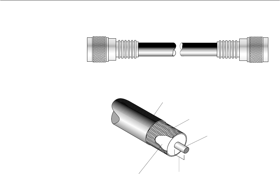
C.1
1027145–0001 Revision E C–2 Terminating IFL cables Hub installation
Figure C-1 shows the main cable components.
Figure C-1 IFL cable components
hb013
Outer jacket
Braid
Center conductor
(solid or stranded copper)
7/32 inch
(6 millimeters)
Dielectric
(foam or flexible plastic)
N connector N connector
IFL cable, terminated - shown without heat-shrink tubing
HNS kit 9006284–0002 contains two N connectors.
Cable parts and
terminolo
gy
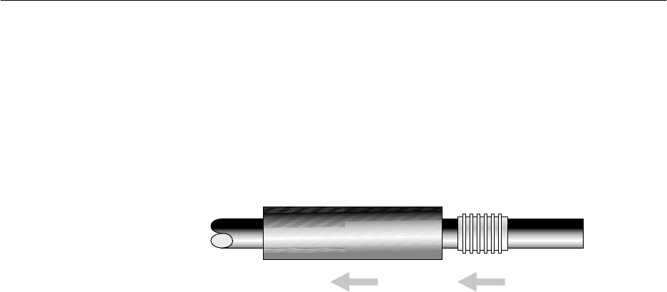
C.2
1027145–0001 Revision E Terminating IFL cables C–3Hub installation
Prepare the cable end as follows:
1. Inspect the cable end for damage from handling and trim off
any damaged portions.
2. Cut the cable as cleanly and squarely as possible.
3. Slip the crimp ring and a piece of heat–shrink tubing
(HNS9007488–0005) onto the cable, as shown in figure
C-2.
Figure C-2 Slipping the crimp ring and
heat–shrink tubing onto the cable
Heat-shrink tubing Crimp
ring
hb014
Butt-cut
cable end
4. Use the spin–stripping tool (Excelta CX 1–78–1, gold
color–coded) to remove the cable jacket and dielectric,
leaving about 7/32 inch (6 millimeters) of the center
conductor exposed, as shown in figure C-3.
a. Open the stripping jaws of the spin–stripping tool
enough to allow the cable end to enter the cable
barrel fully. (See figure C-3.)
b. While holding the cable firmly in the tool and tightly
against the cable stop, squeeze the stripper jaws.
c. Rotate the tool around the cable two or three times
until the outer cable jacket and dielectric are
completely cut through, but do not score the center
conductor. Rotate the tool in the direction indicated in
figure C-3.
d. Remove the cut–off end of the cable jacket and
dielectric.
Preparing the cable
end
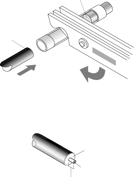
1027145–0001 Revision E C–4 Terminating IFL cables Hub installation
Figure C-3 Using the spin–stripping tool to
expose the center conductor
hb012
Stripper
jaws
Gold-colored
cable stop
Barrel
Butt-cut
cable end
Squeeze and rotate
tool to strip cable.
2.
1. Insert cable
into barrel.
3. Remove jacket and dielectric
to expose center conductor.
Jacket
Dielectric
Center conductor
7/32 inch
(6 millimeters)
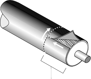
1027145–0001 Revision E Terminating IFL cables C–5Hub installation
5. Using a razor knife, carefully slit the outer jacket as shown
in figure C-4.
Cut around the cable; then cut from the cable end to the first
cut. Cut completely through the jacket, but do not cut into
the braid.
6. Using the razor knife or a pair of diagonal cutters, lift the
jacket and peel it away as shown in figure C-4.
Remove jacket.
hb016
1
2
5/8 inch
(16 millimeters)
Figure C-4 Cutting and removing the jacket
7. Check:
- Braid for nicked or broken strands
- Dielectric end for a straight cut
- Center conductor for nicks and a straight cut
If you see significant damage to the braid, dielectric, or
conductor, you must cut the cable and start over. (Start
with step 1.)
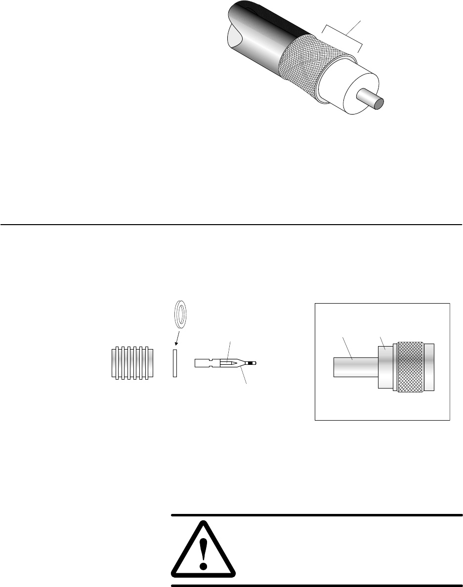
C.3
1027145–0001 Revision E C–6 Terminating IFL cables Hub installation
8. Flare the braid slightly and trim to 7/16 inch (11
millimeters), as shown in figure C-5.
Jacket
Braid
hb093
7/16 inch
(11 millimeters)
Figure C-5 Braid, flared and trimmed
9. Cut approximately 1/4 inch (6 millimeters) of the excess
braid so that all braids will be under the crimp ring when
the connector is completed.
The following steps explain how to attach the IFL (N) connector.
The same type of connector is used at both ends. The connector
includes a plastic guide pin to protect the dielectric during
installation, as shown in figure C-6.
Figure C-6 IFL (N) connector (HNS 9006284–0002)
Crimp
ring
Insulating
washer
Center
pin
Plastic
guide
pin
T0006020
Support
shoulder Jam
nut
Connector body
Collar
Do not remove the plastic guide pin until instructed to do so
(step 4 on page C–8).
CAUTION
Do not install the center pin without the
plastic guide pin—doing so will damage
the dielectric material inside the connector
body.
Attaching the
connector
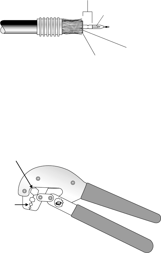
1027145–0001 Revision E Terminating IFL cables C–7Hub installation
To install the cable connector, follow these steps.
1. Place the insulating washer against the dielectric.
2. Push the center pin (with guide pin attached) over the cable
center conductor, as shown in figure C-7.
Figure C-7 Installing the insulator and center pin
T0006021
Crimp
area
Center
pin
Guide pin
Crimp flush
with washer.
Insulating
washer
3. Use the HCT–231 crimp tool (figure C-8) to crimp the
center pin flush with the washer, as shown in figure C-7.
If the center pin is bent after crimping, cut the cable,
re–strip it, and attach a new center pin.
HCT - 231
Use
setting to crimp
center pin.
0.108
Use setting to crimp
the crimp ring
0.475
—but not yet.
This is a later step.
hb021
Figure C-8 Crimping tool
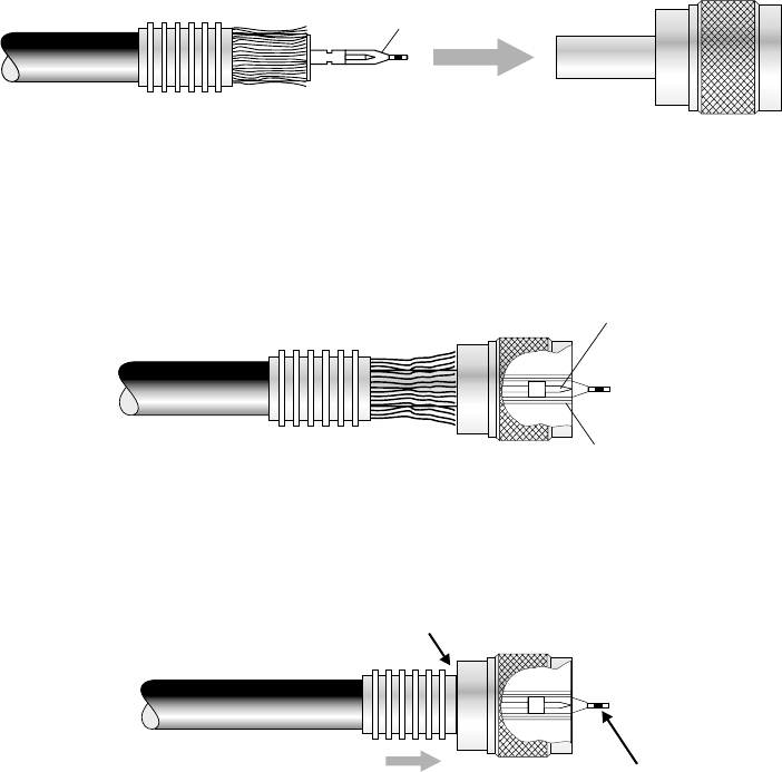
1027145–0001 Revision E C–8 Terminating IFL cables Hub installation
4. Follow the instructions in figure C-9 to install the connector
body and crimp ring, and remove the guide pin.
hb022
Connector
body
Guide pin and
center pin
1. Insert guide pin through back of
connector body until the cable stops.
Crimp
ring Center pin
Guide pin
Ground socket
Center pin inside connector body
Slide crimp ring over
braid and into recess.
2. Remove and
discard guide pin.
3.
Recess
Figure C-9 Installing the connector body and crimp ring
5. Important: Verify that the center pin aligns flush or
within 1/64–inch from the ground socket edge.
If the pin is not flush or within this range, the connection
will probably be faulty.
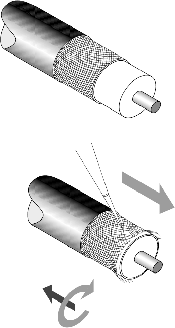
1027145–0001 Revision E Terminating IFL cables C–9Hub installation
6. Comb the braid only if the crimp ring will not fit over the
shoulder and braid. If the crimp ring fits over the
shoulder and braid, skip to step 7).
a. Insert a pick or scribe into the braid and carefully
comb the strands as shown in figure C-10.
Start combing at the cut end. Comb the strands
around the entire perimeter. Work backward, from the
cut end toward the jacket—but always combing away
from the jacket, as shown in figure C-10.
Figure C-10 Combing the braid
Jacket
Braid
Comb action
Direction of travel hb017
Note: Comb the braid all the way back to the jacket.
If part of the braid is uncombed at the jacket end,
stretching will cause the jacket and center pin to
become loose, resulting in poor conductivity.
b. Re–trim the braid to 7/16 inches (6 millimeters), as
shown in figure C-5.
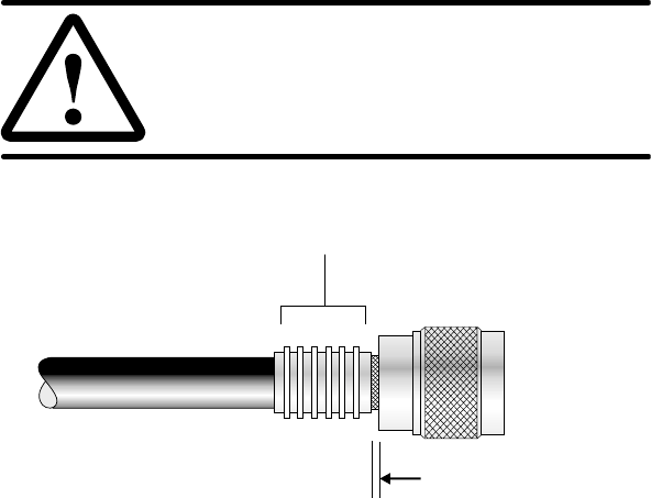
1027145–0001 Revision E C–10 Terminating IFL cables Hub installation
7. While holding the connector assembly together snugly,
position the HCT–231 crimping tool, at setting 0.475, onto
the area shown in figure C-11 and securely crimp the crimp
ring into place.
CAUTION
To avoid damaging the connector body,
make sure the crimping tool does not
touch the connector jam nut.
Crimp
hb024
Maximum gap
(exposed braid):
0.03 inch (0.8 millimeter)
Best if no gap.
Figure C-11 Crimp location
Note: If the crimp ring slips and results in a gap greater
than 0.03 inch (0.8 millimeter) between the crimp ring and
the connector collar, reject the connection. Cut off the
connector and start over.
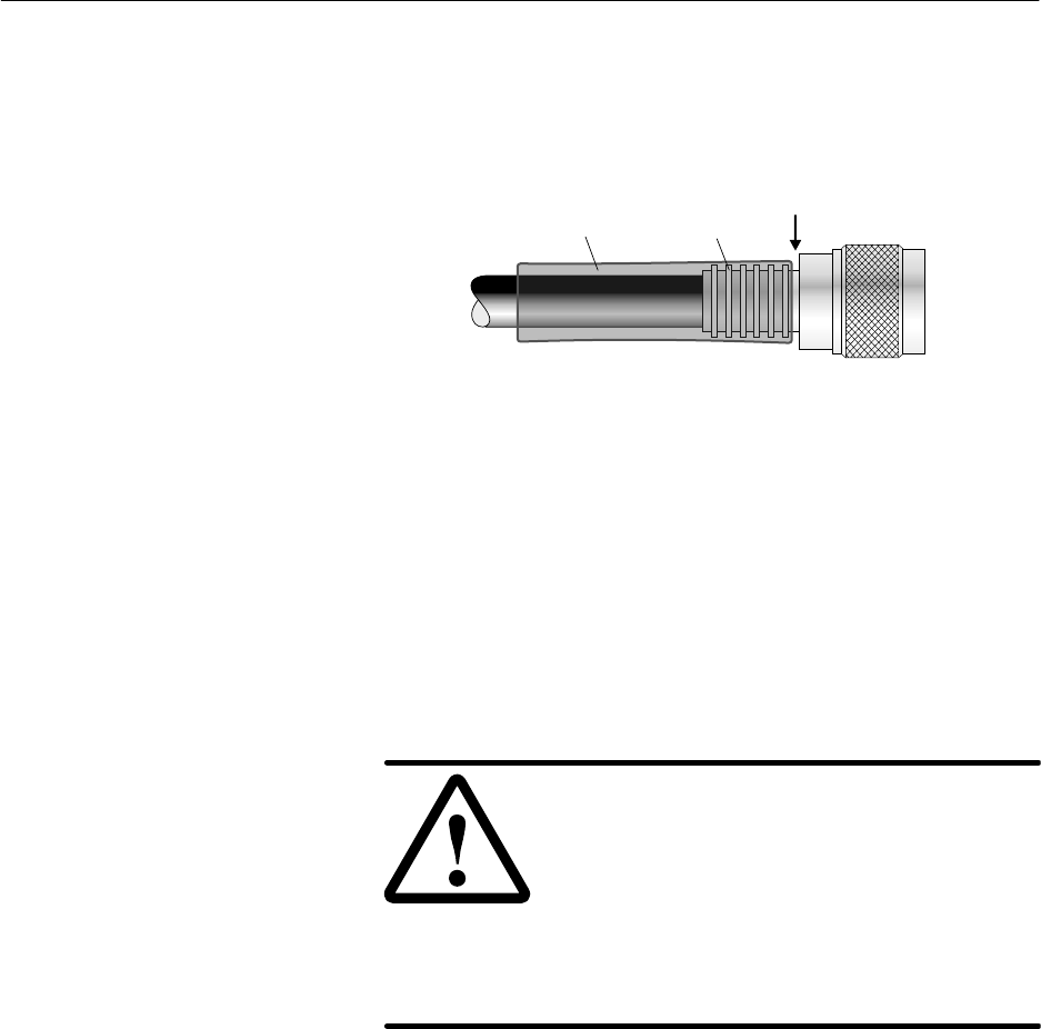
C.4
1027145–0001 Revision E Terminating IFL cables C–11Hub installation
Apply the heat–shrink tubing as follows:
1. Position the heat–shrink tubing near (but not touching) the
jam nut, so it covers the crimp ring and a portion of the
connector collar, as shown in figure C-12.
Figure C-12 Heat–shrink tubing,
properly placed for shrinking
Heat-shrink
tubing
hb026
Collar Jam
nut
Crimp
ring
2. Using a heat gun, heat-shrink the tubing until it snugly fits
around the cable, crimp ring, and part of the connector
collar.
Point the connector upward. Begin heating at the connector
end, and work toward the cable. The adhesive should flow
away from the jam nut.
CAUTION
Do not allow the cable jacket and dielectric
to overheat. This can damage the cable and
cause cable failure.
During heating, the tubing may shift and
the adhesive lining may bleed. Make sure
the adhesive does not bleed onto the jam
nut and damage the connector.
To install an additional N connector, repeat all steps above,
beginning with the section Preparing the cable ends (page C–3).
Applying
heat–shrink tubin
g

1027145–0001 Revision E Index-1
Index
A
Abbreviations (identified), A- 1
Access, buildings and equipment locations, 2–2
Acronyms (identified), A- 1
Adding SSIs, 10–2
Adjusters for antenna azimuth and elevation,
4–11, 4–22
Aligning the HT antenna, 4–6
Antenna
adjusting azimuth, 4–18
fine adjustment, 4–22
adjusting elevation, 4–20
fine adjustment, 4–22
attaching to the antenna mount, 4–15
replacing, 10–6
Antenna bracket, changing left–right orientation,
4–15
Antenna mount
installing, 4–10, 4–13
parts (illustrated), 4–10
torque, 4–19, 4–21
torque wrench, 4–5
AT M . See OC3c–ATM SSI
Azimuth
adjusting, 4–18
fine adjustment, 4–22
explained and illustrated, 4–18
Azimuth/elevation adjusters. See Adjusters (to
adjust azimuth or elevation)
B
Ballast. See Concrete blocks
Bend radius (IFL cable), 5–7, 5–13
Blocks. See Concrete blocks (ballast)
Boot message, 7–5
Boot up sequence, 7–5
Buttons on CCM, 6–35
functions, 6–36
C
Cable length
DS3–TDM SSI, 6–28
DS3–transparent SSI, 6–29
IFL, 5–4
OC3c–ATM SSI, 6–29
Canadian Interference–Causing Equipment
Regulations, B–2, B–3
Canadian Standards Association, B–2, B–3
CCM
See also LCD
Boot message, 7–5
boot up sequence, 7–5
button functions, 6–36
buttons on front panel, 6–35
configuration downloading, 7–6
devices, 7–5
functions, 6–26
illustrated (front panel), 6–26
installing, 6–26
interfaces (clock and LAN), 6–28
LEDs, 6–37
indications, explained, 6–28
operational state, 7–6
power–on test, 6–37
replacing, 10–10
software downloading, 7–6
status, 7–7
SUDS, 6–38
troubleshooting, 9–2
CCM redundancy bus cable, 6–34, 7–2
Channel and control module. See CCM
Chassis. See IDU chassis
Checklist
installation tasks, 1–3
materials, 2–6
tools, 2–3
Commissioning
prerequisites, 2–7, 7–2
procedure, 7–3
Compass, 4–6
Components to be installed, 1–3
Concrete blocks (ballast), 3–10
arrangement on mount, 3–11
1027145–0001 Revision EIndex-2
Configuration downloading (CCM), 7–6
Connections
checking, 6–37, 8–3
weatherproofing, 8–2
Corrugated metal roof, 3–11
Crimp tool, C–7
Customer equipment, connecting, 8–3
Customer sign–off, 8–3
D
Devices, CCM, 7–5
Diagnostic mode, 6–35
Diameter of ODU mast, 4–5
Dismantling an HT, 10–14
Documents, related, vii
Drawings
hub network schematic, 2–1
hub reference drawing, 1–2
hub rooftop drawing, 2–1
DS1 test, 7–11
DS1 test (fractional DS1), 7–15
DS3 test, 7–13
DS3 test (fractional DS3), 7–17
DS3–TDM SSI, 6–28
DS3–transparent SSI, 6–29
E
Element Management System. See EMS
Elevation
adjusting, 4–20
fine adjustment, 4–22
explained and illustrated, 4–20
Emissions, B–2, B–3
EMS, 2–7, 7–2
database, 7–2
Equipment from other vendors, vii
equipment to be installed, 2–1
Ethernet switch (for hub LAN), description, 6–39
Existing structures as ODU mounts, 3–13
Exit (LCD), 6–36
F
FAILED message, 7–4
Failure indication on CCM LCD, 6–39
FCC, B–2, B–3
Fractional DS1 test, 7–15
Fractional DS3 test, 7–17
Front panel display. See LCD
G
Grounding
lightning arrestor, 5–12
ODU, 4–25
power supply
ac, 6–14
dc, 6–16, 6–17
dual ac or dc, 6–12
rack, 6–6
H
Handling materials, 3–4
Heat–shrink tubing (for IFL cable) , C–3, C–11
HT
defined, 1–2
dismantling, 10–14
HT alignment direction, 4–6
HT Disabled message, 7–3, 7–6
HT Enabled message, 7–3, 7–6
HT to RT connections tests, 7–11
Hub LAN router, description, 6–39
Hub LAN switch, description, 6–39
Hub rack, 6–2
grounding, 6–6
installing, 6–2
concrete floor, 6–3
wood floor, 6–4
lifting, 6–3
location, 6–2
Hub terminal. See HT
1027145–0001 Revision E Index-3
I
IDU, 6–7
See also IDU chassis
components, 6–7
illustrated, 6–7
standards compliance, B–3
IDU chassis
See also IDU
connecting the IFL, 6–33
dccircuit breaker, 6–22
disconnect device, 6–22
power–off circuit, 6–22
powering off, 6–22
LCD. See LCD
power supply, 6–8, 6–11
ac, 6–13
connecting power, 6-15
grounding, 6-14
dc, 6–16
connecting power, 6-18
grounding, 6-17
dual ac or dc, 6–11
power–on test, 6–25
rack mounting, 6–8
options, 6–8
replacing, 10–8
slots, numbering of, 6–7
specifications. See Hub and Remote Terminal
Site Preparation Guide
temperature, 6–8
types, 6–8
IEC, B–3
IFL, replacing, 10–12
IFL cable
bend radius, 5–7, 5–13
connecting to CCM (IDU), 6–33
connecting to ODU, 5–15
connections, 5–3
finishing the installation, 5–16
installing inside the building, 5–7
installing on the roof, 5–13
length, 5–7, 5–13
maximum, 5–4
moisture contamination, 8–2
penetration sleeve, 5–6
plan, 5–3
plenum (in conduit with power cables), 5–4
routing guidelines, 5–4
specifications, 5–2
terminating, C–1
testing, 5–15
UL requirements, 5–2
weatherproofing connections, 8–2
Immunity, B–3
Inclinometer, using, 4–21
Indoor unit. See IDU and IDU chassis
Inspecting the installed equipment, 8–3
Installation checklist, 1–3
Installation summary, 1–3
Installers
number needed, vii, 3–4, 6–3
qualifications, vii
Intrafacility link. See IFL cable
L
LAN connection, troubleshooting, 9–4
LCD, 6–35, 6–38
See also CCM
Boot message, 7–5
boot up sequence, 7–5
button functions, 6–36
buttons (for scrolling, selecting), 6–35
configuration downloading (CCM), 7–6
diagnostic mode, 6–35
exit, 6–36
FAILED message, 7–4
HT Disabled message, 7–3, 7–6
HT Enabled message, 7–3, 7–6
menu map, 6–36
operational state, 7–6
software downloading (CCM), 7–6
status conditions (explained), 7–7
status of CCM, SSIs, or ODU, 7–7
SUDS (diagnostics) sequence, 6–35, 6–38,
7–4
SUDS Completed message, 7–4
LEDs
CCM, 6–37
indications, explained, CCM, 6–28
SSIs, 6–31
Lightning arrestor (for IFL), 5–3, 5–8
grounding, 5–12
Lightning protection, 4–26
Liquid crystal display. See LCD
Location
hub rack, 6–2
IDU, 6–8
ODU, 3–3
1027145–0001 Revision EIndex-4
M
MAC address, 7–2
Magnetic declination, 4–6
Main Menu (CCM LCD), 6–35
Maintenance, 10–1
Maps
local, requirements, 2–4, 4–5
magnetic declination, 4–6
plotting HT alignment directions, 4–6
true north, 4–6
Mast, diameter, 4–5
Mast mount, 3–2
location, 3–3
standard type, 3–6
assembly instructions, 3–6
types, 3–5
using existing structures, 3–13
Materials
handling, 3–4
required for installation, 2–6
Menu map for CCM LCD, 6–36
Moisture contamination, 8–2
Mounts. See Mast mount and Antenna mount
Moving SSIs, 10–2
Multiple IFL cables, 5–10
N
N connectors
attaching to IFL cable, C–6
location (IFL cable), 5–3
National Electric Code (NEC), B–2
O
OC3c–ATM SSI, 6–29
ODU, 4–1
connecting the IFL cable, 5–15
grounding, 4–25
illustration, 4–3
location, 2–1
replacing, 10–3
standards compliance, B–2
status, 7–9
transporting to the roof, 4–5
ODU location, 3–3
Operational state, 7–6
possible states, 7–6
Outdoor unit. See ODU
P
Penetrating the roof, 5–5
Penetration sleeve, 5–6
Personnel
number of installers, vii
qualifications, installers, vii
Power input requirement
ac power supply, 6–13
dc power supply, 6–16
Power supply (IDU), 6–8, 6–11
ac, 6–13
connecting power, 6–15
grounding, 6–14
power input requirement, 6–13
dc, 6–16
connecting power, 6–18
grounding, 6–16, 6–17
power input requirement, 6–16
powering off, 6–22
dual ac or dc, 6–11
See also Power supply (IDU), dc
grounding, 6–12
Power–on test
CCM, 6–37
IDU chassis, 6–25
Prerequisites
commissioning, 2–7, 7–2
installation, 2–1
Publications, related, vii
Q
Qualifications for installers, vii
R
Rack
See also hub rack
mounting, 6–8
options, 6–8
safety guidelines, 6–8
Redundancy bus cable, 6–34, 7–2
Related publications, vii
Remote terminal (RT) installation, vii
Repairs, 9–6
1027145–0001 Revision E Index-5
Replacing
antenna, 10–6
CCM, 10–10
faulty components, 9–6
IDU chassis, 10–8
IFL, 10–12
ODU, 10–3
SSIs, 10–11
transceiver, 10–4
RF arrestor, 5–9, 5–14
Roof types, 3–5
corrugated metal, 3–11
Router (for hub LAN), 1–2, 6–2, 6–6
configuration, 7–2
description, 6–39
S
Safety information, ix
rack mounting, 6–8
Sectors, definition and terminology, 4–9
Service loops, 5–7
Service–specific interface. See SSI
Site Data Record, 2–1
Site preparation, vii
Slots, IDU chassis
numbering of, 6–7
where CCM and SSIs are installed, 6–26,
6–28, 6–29, 7–8
Software downloading (CCM), 7–6
Spin–stripping tool (for IFL cable), C–3
SSIs, 7–2
adding, 10–2
DS3–TDM, 6–28
DS3–transparent, 6–29
function, 6–28
hot swapping, 10–2
installing, 6–30
chassis slots, 6–29, 10–2
LEDs, 6–31
moving, 10–2
numbering, 7–8
OC3c–ATM, 6–29
replacing, 10–11
status, 7–8
types, 6–28
Standards compliance, B–1
Startup diagnostics. See SUDS
State, 7–6
Status of CCM, SSIs, or ODU, 7–7
SUDS, 6–35, 6–38, 7–4
failure indication, 6–39
test and display sequence, 6–35, 6–38
SUDS Completed message, 7–4
Summary of installation, 1–3
Switch (for hub LAN), description, 6–39
T
Task checklist, 1–3
Temperature, IDU chassis, 6–8
Terminating the IFL cable, C–1
Test set, 2–5
Testing
DS1 test, 7–11
DS3 test, 7–13
fractional DS1 test, 7–15
fractional DS3 test, 7–17
HT to RT connections, 7–11
IFL cable and connectors, 5–15
Tools required for installation, 2–3
Torque
antenna mount, 4–19, 4–21
rack safety bolts, 6–4
Torque wrench for antenna mount, 4–5
Transceiver
attaching to the antenna, 4–23
replacing, 10–4
Transmission equipment, 1–3
Troubleshooting, 9–1
CCM, 9–2
HT Disabled message, 9–6
LAN connection, 9–4
True north, 4–6
U
Underwriters Laboratories (UL), B–2, B–3
W
Warnings (safety), explained, ix
Weatherproofing, 5–14, 8–2
Wrist strap (ESD), 6–26, 6–30