Hughes Network Systems PASS-TCU Cellular/ PCS GSM Transceiver User Manual PASS TCU USER MANUAL
Hughes Network Systems Cellular/ PCS GSM Transceiver PASS TCU USER MANUAL
Users Manual

PASS-TCU
USER MANUAL

PASS-TCU User Manual 2
Copyright © 2008 Hugjhes Network Systems, LLC.
All rights reserved. This publication and its contents are proprietary to Hughes Network Systems, LLC.
No part of this publication may be reproduced in any form or by any means without the written permission
of Hughes Network Systems, LLC., 11717 Exploration Lane, Germantown, Maryland 20876.
Hughes Network Systems, LLC., has made every effort to ensure the correctness and completeness of the
material in this document. Hughes Network Systems, LLC., shall not be liable for errors contained herein.
The information in this document is subject to change without notice. Hughes Network Systems, LLC.
makes no warranty of any kind with regard to this material, including, but not limited to, the implied
warranties of merchantability and fitness for a particular purpose.
Trademarks
Trademarks, marks, names or product names referenced in this publication are the property of their
respective owners, and Hughes Network Systems, LLC. neither endorses nor otherwise sponsors any
product or services referred to herein.
HUGHES and Hughes Network Systems are trademarks of Hughes Network Systems, LLC.

PASS-TCU User Manual 3
1 Table of Contents:
1 Table of Contents:...................................................................................................................................... 3
2 About This Product.................................................................................................................................... 4
3 PASS-TCU Features:................................................................................................................................. 5
3.1 Emergency Call Overview................................................................................................................. 6
3.2 Roadside Assistance........................................................................................................................... 7
3.3 Remote Nearby Service...................................................................................................................... 8
4 Technical Specifications ............................................................................................................................ 9
5 Definitions and Acronyms ....................................................................................................................... 10
6 FCC Compliance...................................................................................................................................... 12

PASS-TCU User Manual 4
2 About This Product
The Personal Assistance and Safety System (PASS) serves as the central platform of a telematics system,
where all telematics-related technologies are deeply integrated. PASS communicates to a central service
center through the communication network device and in turn the service center helps deliver telematics
services to the customer.
PASS handles the communication from the vehicle to the outside infrastructure via various wireless systems.
Besides, a localization manager will ensure proper positioning information for all telematics services.
PASS contains a GPS receiver, cellular transceiver, and modem/transceiver control board.
PASS supports all the telematics services, which are listed below:
• Remote Door Unlock
• Road Side Assistance (R-Call)
• Emergency Assistance (E-Call)
• Automatic Crash Notification (CAN)
• Stolen Vehicle Tracking
• Automatic Maintenance
The access to PASS system functionality is granted via several application programming interfaces from
within the platform or to other in-car applications over the vehicle network system. In that way the
application software will become independent from the used hardware.
PASS can be characterized as a distributed, heterogeneous hardware/ software system, which provides
functionality and services to the customer via the interaction of several devices. These hardware components
are interconnected by standardized car networks (e.g. Discrete I/O line, CAN bus) and by wireless
communication channels (e.g. GSM).
The features accomplished UConnect System Include:
- Bluetooth Hands Free Calling
- Universal Consumer Interface (Portable Music Player Integration)
Additional investigate features are:
- Remote Vehicle Diagnostics and Data Collection
- Off Board Navigation
A separate RFI will also be issued to Customer Service Center operators to provide the ‘back-end’ services.
It is assumed that communication will take place via an integrated cellular modem although other innovative
solutions are always considered.
PASS-TCU User Manual 5
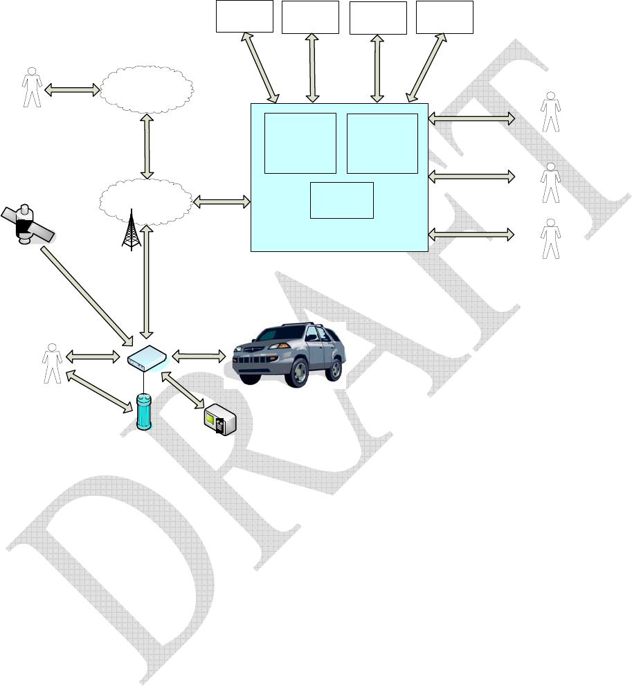
3 PASS-TCU Features:
Subscribers
(Vehicle Owners)
OEM
Dealers
PSAP
Operators
“911”
Wireless Network
Vehicle
Driver/Passengers
PSTN
Telematics
Control Unit
(TCU)
GPS
Satellites
TCU-Equipped
Vehicle
Telematics Operations Center (TOC)
Wireless
Communications
infrastructure Service Center
Network
Management
Emergency
Call Center
Roadside
Assistance
Call Center
Customer
Assistance
Call Center
Concierge
Call Center
Backup
Battery
(BUB)
Diagnostic
Tester
Figure 1: System Context.
PASS-TCU User Manual 6
3.1 Emergency Call Overview
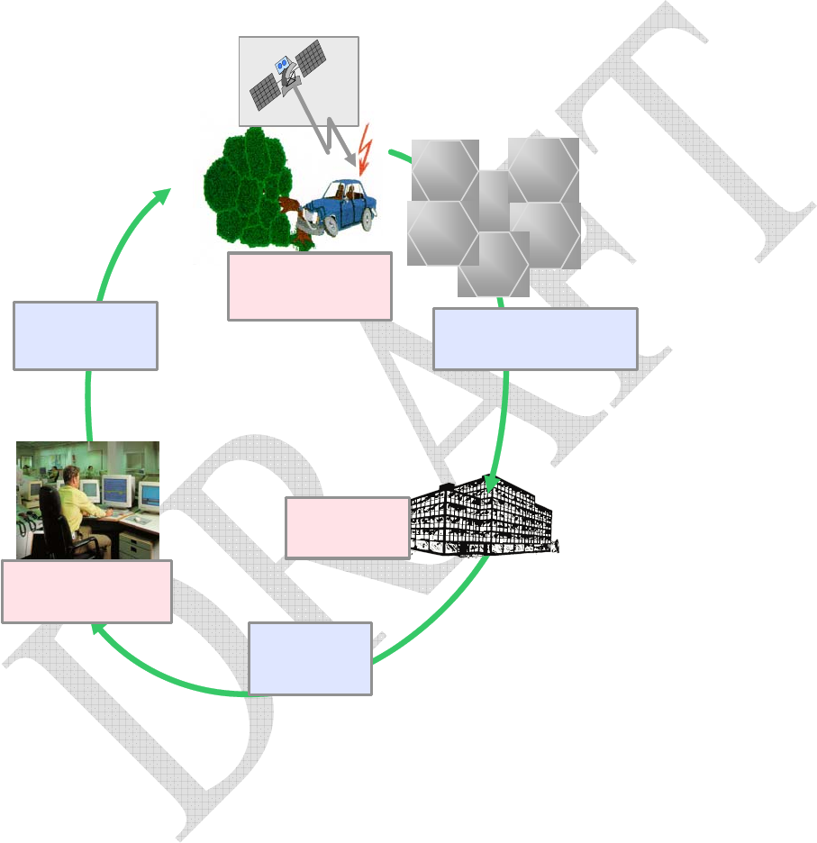
Emergency Call service is activated by the low cost TeleAid unit (PASS) in two different ways:
Manually by pushing an emergency call push-button (Emergency Call button or SOS button) or
Automatically by receiving a crash signal from the external airbag control unit.
Emergency
Location
Emergency
Call Message
Ser vi ce
Cent er
Police Control
Cent er
Voice
Connection Automatic or Manual
Emer genc y Cal l
Cellular
Network
GPS
) Vehicle Position on Map
) Customer Data record
) Selection/ information
operational control center (data
or voice connection)
) Voice connection between
vehicle and Service Center
Figure 2: Emergency Call Overview.
PASS-TCU User Manual 7
3.2 Roadside Assistance Overview
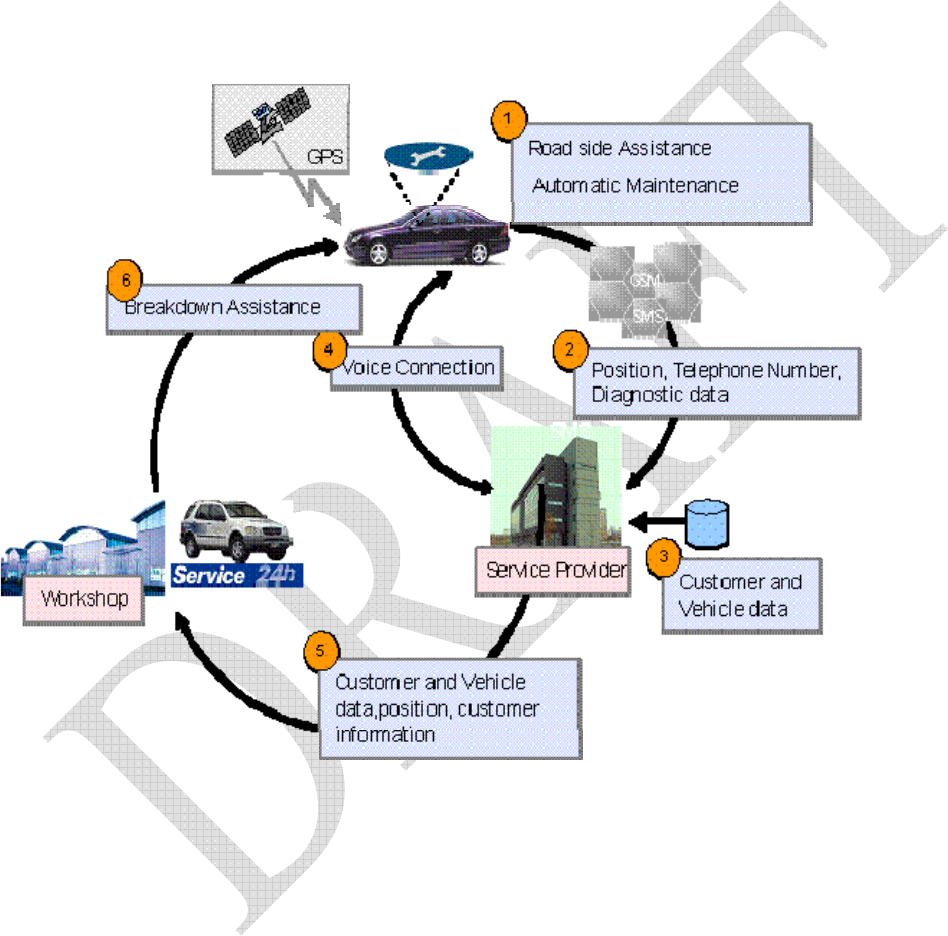
The Roadside Assistance service allows the customer to get in touch with the Service Center in case of a
breakdown of the vehicle or for any non-emergency assistance. A request for the Roadside Assistance can
be triggered by manually pressing a button available within the car. This service allows the service center to
provide quick and efficient assistance to the customer. The service can also be triggered automatically when
predefined thresholds (remaining distance, remaining time) have been reached.
Figure 3: Road Assistance Overview.
PASS-TCU User Manual 8
3.3 Remote Nearby Service Overview
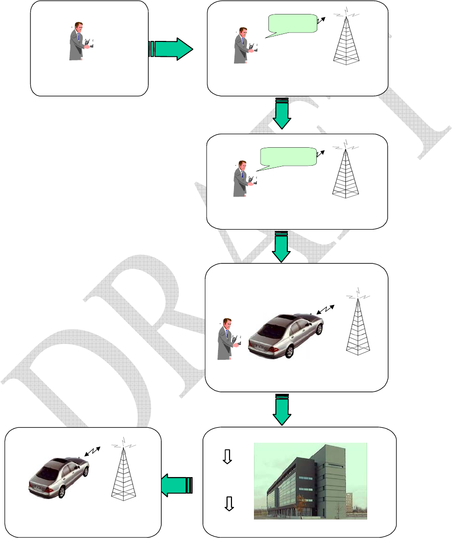
The Remote Nearby service allows the customer to unlock the vehicle, if the customer is nearby the vehicle.
The customer can call the service center to request for the RDU service.
Customer contacts the Service Center
to order service Remote Door Unlock
Unlock
vehicle
Service Center accepts customer‘s order
Transmission of customer‘s order to vehicle
&
'
Customer locked his
vehicle with keys inside
Vehicle accepts Unlock command
and unlocks doors, trunk and tank
Vehicle sends Door Unlock request
to the Service Center
Customer activates the service by
p
ressing the trunk button for 15 sec
Service center requests for password
A
nd customer provides the password
Password
Figure 4: Remote Door Unlock Overview.

PASS-TCU User Manual 9
4 Technical Specifications

PASS-TCU User Manual 10
5 Definitions and Acronyms
OTA: Over the Air
Ambient Temperature: Temperature surrounding the component as tested in a test chamber or as installed
in the vehicle.
Category and subcategory: In this document, electronic modules, electric motors and inductive devices are
classified into categories and subcategories, which determine the appropriate test requirements.
ECU: Electronic Control Unit
DUT: Device Under Test
Component: Any electrical or electronic assembly used in the vehicle, such as engine control module,
instrument cluster, junction block, sensor, switch, etc. Also used interchangeably with terms such as ECU,
Module, Device, DUT, etc.
Ignition Voltage Lines: The supply voltage lines to a DUT that are fed from the vehicle electrical power
distribution system through the ignition switch.
Inductive Device: An electromechanical device that stores energy in a magnetic field. Examples are
solenoids, relays, buzzers and electromechanical horns.
IOD: Ignition Off Current Draw.
IP Class: International Protection classification for solid and/or water intrusion for automotive applications
as described in DIN 40 050.
RKE: Remote Keyless Entry
TPM Sensor: Tire Pressure Monitor Sensor
Non-operational: A component shall be considered “Non-operational”, if it is connected to a power source,
but does not perform any normal operating functions during the test. The condition requires use of mating
connectors during the test. This condition is similar to the one experienced by an E/E component in a parked
vehicle.
NTC: Negative Temperature Co-efficient (Device with NTC feature shuts off power supply or reduces
certain component applications (e. g. CD-playing for a car radio) when device temperature goes below
certain minimum operating temperature specified).
Operational: A component shall be considered "Operational", if it performs functions as experienced during
vehicle operations on a continuous basis (without any interruptions). Power source may be from vehicle
battery, ignition feed or an independent power source, as in case of, RKE, or TPM Sensor, etc.
PET: Parametric Evaluation Technique.

PASS-TCU User Manual 11
Power-off: A component shall be considered "Power-off", when it is not electrically connected to a power
source, as in case of shipping or storage conditions. “Power-off” condition may require use of mating
connectors during some of the tests and shall be specified clearly in the “Test Parameters”.
PTC: Positive Temperature Co-efficient (Device with PTC feature shuts off power supply or reduces certain
component applications (e. g. CD-playing for a car radio) when device temperature goes above certain
maximum operating temperature specified).
PV: Production Validation.
Soak Time (Tsoak): Time taken by component to reach chamber ambient temperature at high or low
temperature during thermal cycling tests from the time chamber temperature reaches corresponding high or
low temperature levels.
Temperature class: Classification of maximum temperature a component will experience based on its
mounting location and specific packaging variations in the vehicle.
Tmin: Lowest ambient temperature experienced by any component (Usually -40 0C).
Tmax: Highest ambient temperature experienced by any component. Value of Tmax depends on temperature
class of the component.
Usage Life Profile (ULP): It is a software tool that assists in selecting the applicable qualification tests and
test parameters for a component based on input data such as design or service life, in-vehicle component
location, customer driving/usage pattern or other environmental stresses.
Vibration Class: Classification of vibration intensities a component will experience based on its mounting
location in the vehicle.

PASS-TCU User Manual 12
6 FCC Compliance
This device conforms to the FCC rules. Any change or modification to Hughes Network Systems’
equipment, not expressly approved by Hughes Network Systems, could void the user’s authority to operate
the equipment.
To comply with the FCC RF Exposure requirements, this device must be operated with a minimum
separation distance of 20 cm or more from a person’s body. Other operating configurations should be
avoided.
This device complies with Part 15 of the FCC Rules. Operation is subject to the following two conditions:
(1) this device may not cause harmful interference, and (2) this device must accept any interference received,
including interference that may cause undesired operation.