Humatics 200EVK-1202 UWB Transceiver (EVK) User Manual I
TDC Acquisition Holdings Inc. UWB Transceiver (EVK) I
UserManual.wiki
>
Humatics
>
200EVK 1202 User Manual
Rev A
Navigation menu
Upload a User Manual
Namespaces
Wiki Guide
HTML
PDF
Info
Views
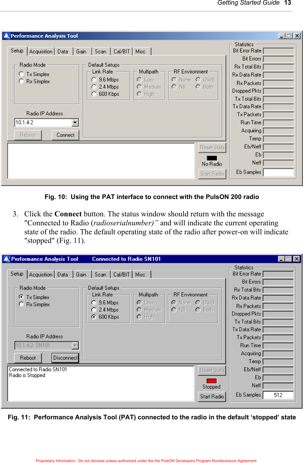
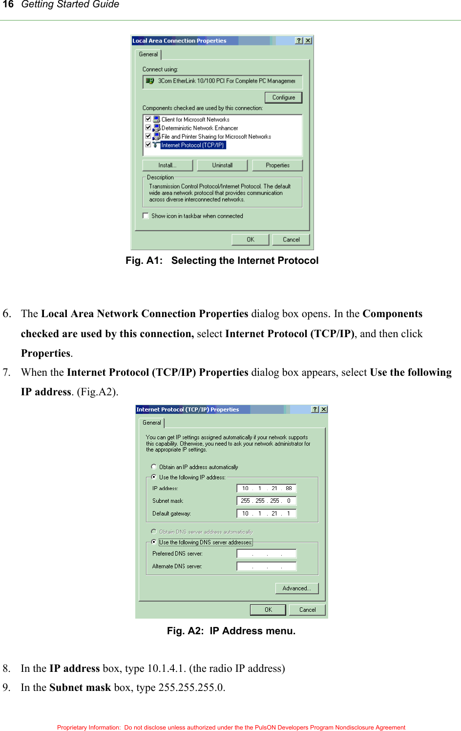
User Manual
Discussion / Help
Navigation