Humatics P330-A Ultra Wideband (UWB) radio transceiver User Manual
TDC Acquisition Holdings Inc. Ultra Wideband (UWB) radio transceiver
Humatics >
User Manual


2 P330 Data Sheet / User Guide
DRAFT
Copyright
All rights reserved. Time Domain® 2001-2017. All rights reserved.
Trademarks
Time Domain®, PulsON®, and “PulsON Triangle” logo are registered trademarks of Time Domain. Microsoft® and
Windows Vista®, Windows 7®, Windows 8®, and Windows 10® are registered trademarks of Microsoft Corporation.
MATLAB® is a registered trademark of MathWorks, Inc. Decawave is a registered trademark of Decawave Limited. Any
trademarks, trade names, service marks or service names owned or registered by any other company and used in this manual
are the property of its respective company.
Rights
Rights to use this documentation are set forth in the PulsON Products Terms and Conditions of Sale.
Document Information
Time Domain reserves the right to change product specifications without notice. Any changes to the functionality or
specifications will be issued as specific errata sheets or will be incorporated in new versions of this document. The latest
version of this document and future documents can be found on the Time Domain website. The name/number and date of
this document can be found on the left side of the cover page.
Regulatory Approvals
The P330, as supplied by Time Domain, has been designed to be compliant with both the US FCC regulations as well as
Europe’s ETSI EN 302 065 standard. As of this publication date, Time Domain is in the process of applying for FCC
certification and expects approval early in 2017. Certification to the ETSI standard is expected later in 2017.
Regardless, the user is free to buy the equipment for evaluation and demonstration purposes (but not for resale) in most
countries. When in doubt, the user should confirm with the relevant authority governing radio emissions.
All final products developed by the user which incorporate the P330 must be approved by the relevant authority governing
radio emissions for the target market country(s). The User bears all responsibility for obtaining such approval(s).

P330 Data Sheet / User Guide 3
DRAFT
TABLE OF CONTENTS
1 SUMMARY 5
2 P330 SOFTWARE 8
2.1 P330 Embedded Software ....................................................................................................... 8
2.2 Application Programming Interfaces (APIs) ......................................................................... 8
2.3 Graphical User Interfaces (GUIs) and Sample Code ............................................................ 9
2.4 API and GUI as Development Tools .................................................................................... 10
2.4.1 Ranging Measurement with RangeNet 10
2.4.2 Networking and Localization with RangeNet 11
2.5 Networking: RangeNet vs. RangeNet Lite ........................................................................... 13
2.6 Software & Hardware Support.............................................................................................. 13
3 HARDWARE BLOCK DIAGRAM 15
4 ELECTRICAL INTERFACES 17
4.1 Connecting to the P330 ......................................................................................................... 18
4.2 Connector Pinouts ................................................................................................................ 18
4.3 Powering and Grounding the Unit ....................................................................................... 22
4.3.1 Powering the P330 through the USB Power Jack vs Locking & Mezzanine Connectors 22
4.3.2 Reverse polarity protection 22
4.3.3 Two means of Powering the P330 22
4.3.4 Chassis Ground 22
4.4 Host to P330 Interface Options ............................................................................................ 23
4.4.1 USB 2.0 High Speed Device 23
4.4.2 User Serial 23
4.4.3 SPI 24
4.4.4 Ethernet and IP Addressing 26
4.4.5 CAN 27
4.4.6 Detection of Failures 27
4.5 GPIO ........................................................................................................................................ 27
4.6 Antenna Port .......................................................................................................................... 28
4.7 RF Transmit and Receive Characteristics .......................................................................... 28

4 P330 Data Sheet / User Guide
DRAFT
4.8 Indicator Lights ..................................................................................................................... 29
4.9 Heat Management ................................................................................................................. 30
4.10 Accessories ....................................................................................................................... 3130
4.10.1 Enclosure 31
4.10.2 Power Supply/Charger with Battery and Cables 3231
5 MECHANICAL INTERFACE 34
6 TECHNICAL SPECIFICATIONS 37
6.1 Summary of Key Performance Parameters ........................................................................ 37
6.2 Maximum Operating Range of a P330 Radio ..................................................................... 39
6.2.1 Fresnel – Key Limit to Operational Range 39
6.2.2 Examples of Operational Range 41
6.3 Range Measurement Rate .................................................................................................... 43
6.4 Range Measurement Precision, Bias and Accuracy ......................................................... 44
6.4.1 Precision in LOS and NLOS Conditions 44
6.4.2 Precision in Fresnel Nulls 44
6.4.3 Bias and Calibration 44
6.4.4 Accuracy 45
6.5 P330 Revisions and Differences .......................................................................................... 46
7 BROADSPEC ANTENNA 47
8 REGULATORY COMPLIANCE 48
8.1 Compliance with the U.S. FCC Regulations ....................................................................... 48
8.2 Compliance with the EU ETSI Standards ........................................................................... 49
9 IMPORT/EXPORT CONSIDERATIONS 51
10 CONFIGURATION AND ORDERING INFORMATION 52

P330 Data Sheet / User Guide 5
DRAFT
1 Summary
Time Domain is dedicated to providing industry with a wide variety of UWB platforms for use as
ranging radios, radars, multi-static radars and communications devices. The P330 is the latest
addition and joins the P400 family of devices.
The P400 family is based on Time Domain’s FIFE UWB chip while the P330 uses the Decawave
DW1000 UWB chip. While both chips support Two Way Time of Flight, the approaches used to
implement this capability were accomplished in very different manners. As a result, both chips have
significant advantages and disadvantages relative to each other. Consequently, there are applications
for which the P330 is ideally suited and others for which the P440 is perfect. For a detailed
discussion of these differences see the document Comparison of P330 and P440.
The P330 was developed by
Leveraging the P000 software interface and RangeNet GUI with
the network and localization capability of the P400
and the Decawave DW1000 ranging chip.
The result is a powerful development platform which will allow the user to build, test and
demonstrate rapid prototypes of end products without needing to first develop the basic hardware and
software necessary to demonstrate the ranging, network or localization capability of the end product.
With the P330 the user will be able to
Quickly demonstrate and quantify the performance of UWB ranging in a target environment
Organize a group of P330s as a self-localizing, network in which each member of the group
computes its own location and report this location and the location of the other P330s in the
area to a host controller
Quickly interface the P330 with virtually any hardware because the P330
o Accepts any voltage from 5.5 to 48volts
o Interfaces to a Host Controller through Serial, SPI, CAN, USB or Ethernet
o Operates from -40 to +85c
o Has excellent performance in high vibration environments
o Has emissions which are compliant with both the FCC regulations and the European
ETSI standards
Easily monitor and control a P330 system through the RangeNet GUI (or use the sample
MATLAB or C code provided with the P330 to develop your own monitor and control
system)
Once a proof of concept has successfully concluded, the user can move to the next step in the product
cycle either by using the P330s as is or by designing a low cost version of the P330 that contains only
the hardware necessary to fulfill the requirements of the project.
The P330 has the following additional features:
It is a coherent Ultra Wideband (UWB) radio transceiver optimized for measuring the
distance between two radios.
It uses the DW1000 UWB chip to measure distance by the Two-Way Time-of-Flight (TW-
TOF) method. These measurements have a precision of 10 cm (3 standard deviations) and a
bias error of +/-2 cm. Ranging rates of 180Hz are possible.

6 P330 Data Sheet / User Guide
DRAFT
It operates in both the low band 3.1-4.8GHz and the high band 6.0-7.0 GHz.
It communicates data between two or more P330s.
A wide range of settings allow ranging performance to be optimized for high ranging update
rates or long range operation.
It is provided with a network (RangeNet) which has been optimized for TW-TOF
measurement. This network can be operated using either the ALOHA (randomized) or
TDMA (Time Division Multiple Access) protocols.
It supports up to 4 independent communications channels thus allowing operation as a
CDMA (Code Division Multiple Access) network.
The network is provided with a localization engine which can be used to determine the
location of the unit in the X, Y and Z dimensions.
The RF emissions are compliant with the United States Federal Communications
Commission (FCC) per Rule Part 15.519.
The RF emissions are compliant with the European Union ETSI EN 302 065 standard mask.
The user monitors and controls the P330 through an Application Programming Interface
(API) over USB, Serial, SPI, Ethernet or CAN connections. USB driver support is provided
for Windows Vista 32/64, Windows 7 32/64, Windows 8 32/64, and Windows 10 operating
systems. Unix and OS X systems do not need a special driver for USB. The P330
automatically appears as a serial device.
The API provides all the commands and capabilities required by a user to design a network
tailored for operating multiple P330s as ranging radios.
To assist the user in demonstrating the performance of the P330, Time Domain also provides
RangeNet GUI, a PC-based Graphical User Interface, which exercises all of the API commands and
offers the following capabilities:
It provides programmers with a visual example of a host application which interfaces to the
P330 through the API.
It allows users to evaluate ranging, communications, network and localization performance.
It allows system analysts to visualize, collect, and log raw ranging data such that it is possible
to develop algorithms/strategies optimized for the chosen product application.
It allows users to operate multiple P330s to form a network of ranging radios which self
locate and report positions to the host.
Time Domain also provides sample C and MATLAB code for demonstrating the interface and
performance of the hardware.
The objective of providing the GUI, sample C and sample MATLAB code is to supply programmers
with several example interfaces and implementations which the user may then replace or tailor with
custom code optimized for their particular needs and applications.
This document describes the P330 hardware and software. This discussion is subdivided into the
following subsections.
Section 2 P330 Software
Section 3 Hardware Block Diagram
Section 4 Electrical Interfaces
Section 5 Mechanical Interface
Section 6 Technical Specifications
Section 7 Broadspec Antenna

P330 Data Sheet / User Guide 7
DRAFT
Section 8 Regulatory Compliance
Section 9 Import/Export Considerations
Section 10 Configuration and Ordering Information
Additional information including all of the documents referenced in this section can be found on the
web at www.timedomain.com. This includes: the API, software manuals, application notes, white
papers, examples, published papers, sample C code, sample MATLAB code, and more.

8 P330 Data Sheet / User Guide
DRAFT
2 P330 Software
The P330 software consists of five elements:
Embedded software operating on the P330 module
The Application Programming Interface (API) which defines the interface between the P330
and a Host processor
The RangeNet GUI which (1) illustrates operation of the P330 and (2) provides an analytical
tool for characterizing performance
Sample C and MATLAB code to assist the user in developing custom applications
The RangeNet network and localizer to enable systems of P330s to range, communicate
efficiently and determine their location
In addition, Time Domain is committed to periodically adding new features and capabilities through
software upgrades.
2.1 P330 Embedded Software
The P330 is a microprocessor-based UWB platform. The embedded software driving the onboard
processor has three principal functions:
It is responsible for controlling and monitoring the operation of the Decawave DW1000
UWB ranging chip.
It handles all communications (Ethernet, USB, SPI, Serial, and CAN) with the user’s Host
processor (typically a PC or single-board computer). It also controls 15 GPIO pins.
When instructed to act as a network, the onboard processor:
o Assumes all responsibilities for scheduling communications and range requests
o Provides the Host with status update information
o Handles supervisory commands sent by the Host
This increases the ranging update rate and significantly offloads the Host processor.
When instructed to compute node locations, the onboard processor will monitor reported
ranges and, based on input from the user, employ either a Kalman Filter based algorithm or a
Geometric solver to compute and report the location of device.
The processor can also monitor communications traffic and report ranges between other units
as well as the location of other units.
2.2 Application Programming Interfaces (APIs)
The communications between the P330 and the Host processor is defined in document 320-0336
P300 RangeNet API Specification. The API consists of a set of commands which allow the user to
initialize, control and monitor the P330 and the DW1000 chip. For example, these commands allow

P330 Data Sheet / User Guide 9
DRAFT
the user to:
Define the DW1000 operating properties (RF bands of operation, communications
characteristics and preamble code)
Generate individual range measurements
Collect statistics on those range measurements
Define a network based on either the ALOHA or TDMA protocol
Define behavior of units in a network. For example, the behavior of a static anchor/reference
node could be different from that of a mobile. It is also possible to allow or prohibit some
units from communicating in the network with other units.
Direct the P330 to compute its location based on ranges generated by the network.
Maintain a data base of all units in the network. Information includes range and location
data as well as other performance statistics.
Upload the contents of the data base to the host on a periodic or automatic basis.
Cause the unit to transition between operating as ranging only device, to operation as part of a
network, to operation as part of a network which localizes.
Buffer and control the flow of communications data between the Host and network
Collect and report various statistics including P330 node id, software versions, and network
performance statistics.
2.3 Graphical User Interfaces (GUIs) and Sample Code
Mastering all of the commands in an API can be a time-consuming task. To accelerate this learning
process, Time Domain provides an example Graphical User Interface (GUI) called the RangeNet GUI
which operates on a PC and exercises all of the API commands. The RangeNet GUI will also display
received data and allow the user to log all received data or API messages sent or received by the Host.
In addition, Time Domain also provides sample C and sample MATLAB code. The sample C code
enables embedded programmers to quickly interface to the P330. The sample MATLAB code
enables system analysts to quickly construct experiments to investigate and evaluate performance or
to build rapid prototypes. The sample code also includes parsers for extracting information from the
logfiles.
The sample code includes the following:
Ranging and Network (RangeNet)
150-0117 – RangeNet Sample C Applications
150-0118 – RangeNet Sample MATLAB Applications
150-0103 – Ranging Sample C Applications
150-0104 – Ranging Sample MATLAB Applications

10 P330 Data Sheet / User Guide
DRAFT
The RangeNet GUI is provided with a User Guide (320-0338 P300 RangeNet User Guide) and a
Quick Start Guide (320-0337 P300 Ranging and Location Quick Start Guide) that illustrate operation
of the equipment. Within 1 hour of receiving the equipment, the user will be able to measure range,
operate a network and localize.
2.4 API and GUI as Development Tools
This section provides a high level summary of the API and discusses how the RangeNet GUI can be
used as a development tool.
In general, the RangeNet GUI performs as one would expect. It allows the user to configure the
P330s, initiate range requests, move in and out of a network, calculate location, move to and from
different sleep states, measure the P330 temperature, display status, hardware and software version
numbers as well as other useful information. In addition, the RangeNet GUI allows the user to
display and log collected data as well as all communications between the Host and the P330.
2.4.1 Ranging Measurement with RangeNet
The RangeNet GUI allows the user to configure the P330 and take range measurements. The P330
supports the following two forms of range measurement.
Precision Range Measurements (PRM) are taken using the TW-TOF ranging technique. These
readings typically have high accuracy and are provided with estimates of range error as well as flags
that warn of possible errors. The user can use these range error estimates to drive a Kalman Filter.
The flags can be used to disregard inaccurate readings.
Echo Last Range (ELR) measurements are Precision Range Measurements which have been taken
between two other radios in the system. In other words, any time a unit takes a PRM it will broadcast
the last range measurement it took to any other radios in the area. For example, if Unit A measures
the distance between Unit A and Unit B, it will broadcast this range measurement to Units C, D, E,
etc., whenever it next initiates a range measurement. This is an alternate way of automatically
distributing range information through a system.
The RangeNet GUI allows the user to configure the unit and take range measurements. It also adds
an extra level of system software in that it will allow the user to:
Request a single range measurement, a fixed number of measurements, or a continuous series
of range measurements.
Display various DW1000 sources performance statistics including: Max Noise, STD Noise,
First Path, First Path Amplitude 1, First Path Amplitude 2, First Path Amplitude 3, RX
Preamble Count, and Max Growth CIR.
Compute and display P330 statistics including: Range Error Estimate, First Path Power and
RX Power (according to Decawave’s published algorithm), Range Status, and the number of
milliseconds required to take a measurement.
Display quality metrics that provide a warning if the reading is suspect.
Calculate performance statistics. For example, if the user requests a finite number of ranges,
the RangeNet GUI will compute the range success rate, the average range, the standard
deviation of the range measurements, and the average First Path Power.
Recalibrate a given link such that the bias or offset inherent in a range measurement can be
compensated.
P330 Data Sheet / User Guide 11
DRAFT
Allow the user to easily enter and transmit data.
Allow the user to receive and display data.
Log all messages exchanged between the Host and connected P330.
Display range measurements taken between other units in the area for which the connected
P330 is not a direct participant.
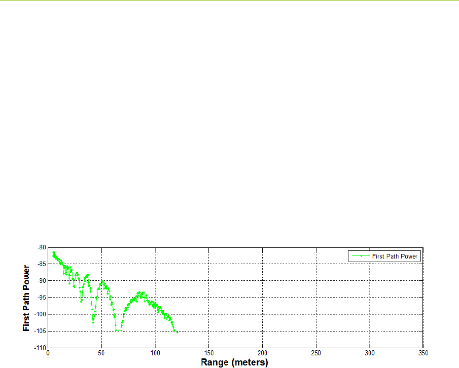
The ability to log data also allows the user to plot performance as a function of range. This is an
excellent tool for evaluating signal propagation in a given area. For example, the information shown
in Figure 2-1 was collected as the distance between two units was increased. Basically, data was
logged with one unit held stationary while the second unit was driven away. Figure 2-1 is a plot of
the received signal strength (First Path Power) as a function of separation distance. In this figure one
can observe several items of note:
There is a major Fresnel cancellation at 60and 130 meters as well as minor ones between 20
and 40meters.
The minimum sensitivity of this unit is -105db.
Fig. 2-1: Received signal strength (First Path Power) as function of separation distance.
2.4.2 Networking and Localization with RangeNet
Operating a system that consists of only two units is very simple. Operating with more than two units
starts to introduce significant complexity which is increased even further when the need to determine
location is added. For example:
There needs to be a way to prevent units from interfering with each other.
The number of radios in the system may vary with time. Units that enter the system need to
be discovered. Units that exit the system need to be removed from the network.
Not all units need to behave the same way. Some units might initiate and respond to range
measurement requests. Some might only initiate requests. Some might only respond. Some
units might only communicate with a subset of the system.
Before you can convert range into location it is necessary to define a coordinate system and
measure the position of anchor (fixed reference) units relative to that system.
The X,Y,Z location of the references needs to be communicated with all of the anchors.
Since ranges are taken while a unit is moving, simple trilateration may not produce valid
locations. It is therefore necessary to include in the location solving engine a Kalman Filter
to both filter out noise and better compute locations.

12 P330 Data Sheet / User Guide
DRAFT
The RangeNet API allows the user to define a network and to define the behavior of the radios in the
system. Operation of the network is controlled by the P330. In particular, the P330 is responsible for
scheduling range requests, maintaining all of the neighbors in a database, and passing data between
the Host and the network. The Host computer function is thereby limited to monitoring and
supervision, thus significantly offloading its responsibilities.
The RangeNet API provides the user with tools to define and monitor the network. For example:
The network can be defined using two different time-sharing protocols: ALOHA
(randomized) or TDMA (Time Division Multiple Access).
If the ALOHA protocol is used, then the average interval and the random variation of that
interval can both be defined. The average interval can be manually or automatically throttled
based on the number of units in the system. Radio behavior can be limited on a per unit basis
such that some units initiate and respond to range requests, while others initiate-only or
respond-only. In addition, some units can be instructed to limit their interactions to a subset
of the network members. While most ALOHA networks have an efficiency of 19%, the
efficiency of this ALOHA network is approximately 38%, making it equivalent to the
performance of a Slotted ALOHA system.
If the TDMA protocol is used, then the user can define a slot map that provides each radio
with instructions on when and to whom and with what parameters it should communicate.
Because the P330 supports multiple communications channels, it is possible to operate either
the ALOHA or TDMA protocol with a CDMA overlay.
Because the P330 network schedules range requests, it avoids the overhead of Host to P330
communications and can therefore run at a higher ranging rate.
The P330 network maintains a neighbor database. Besides noting all of the members of the
network and their ranges, this database also contains a large body of statistics and other
useful information. For example, the database includes received signal strength, approach
velocity, effective ranging rate, and signal quality.
The RangeNet API also provides the user with the ability to enable the P330s to compute their
location based on ranges generated by the network. This capability does not limit the user’s ability to
independently construct a Host based localizer.
The P330 API supports three localization modes: IDLE (awaiting instructions), Autosurvey
(anchors use UWB ranging to self locate) and Tracking (P330s compute position in the
system and report)
The API allows the Host to connect to any unit and use that connection to report the location
of any unit in the system as well as all of the range measurements taken in the system.
Based on instructions from the user, the P330 will compute either X and Y locations or X, Y
and Z locations, variance and covariance information and report those values through the
API.
While these are all powerful network tools, the complexity inherent in this richness can make it
difficult to visualize operation through just the API. The RangeNet GUI fills this gap. Not only does
the RangeNet GUI allow the user to configure the system, but it also provides a means for easily
maintaining different configurations, monitoring results, evaluating the performance of individual
links in the network, monitoring the neighbor database, reporting location information and quality
statistics from all units in the system. For example, the RangeNet GUI allows the user to:
Define all types of configuration information (including TDMA slot map, ranging

P330 Data Sheet / User Guide 13
DRAFT
configuration details, ALOHA setup information, neighbor database characteristics),
download it to the P330, store that configuration to disk, and recover from disk any given
configuration.
Monitor the database at whatever update rate the user finds useful.
Send, receive, and display data.
Display waveform scans, range measurements and location measurements as well as
relevant metrics and statistics associated with a particular links.
While all the functions mentioned so far are performed by the P330 processor and reported to the
GUI, additional location related capabilities have been included in the RangeNet GUI. For example:
The Autosurvey capability has been implemented through the RangeNet GUI. When
engaged, the units in the system will be ordered to range to each other and these ranges will
be reported to the GUI. The GUI will compute anchor locations until such time that the
standard deviation of the location measurements has achieved a user defined threshold.
Once the locations of the anchors have been defined (either through Autosurvey or manual
survey with a laser theodolite) the GUI will then broad cast locations information to all of the
units in the system. The P330 based network uses a flooding algorithm to distribute this
information through the system and an active confirmation system to verify that the
information has been successfully distributed..
Once the system transitions to Tracking Mode, the GUI will display, in real time, the location
of all of the units in the system.
The GUI also allows the user to define, display and add GPS like waypoints to the system.
2.5 Networking: RangeNet vs. RangeNet Lite
RangeNet Lite is a node-limited version of RangeNet and is intended to allow users to evaluate and
test before considering licensing or purchasing the unrestricted version. RangeNet Lite is provided
with all Ranging and Localization Development Kits, as well as the PulsON Lab and MegaLab
packages. It is node-locked in that the Lite version will support all of the features of RangeNet as
long as the system size is limited to 10 nodes or less. More specifically, the first 10 nodes that join
the system will operate normally. They can join and leave the network normally, but the 11th unit
and all subsequent units will not be recognized by the system. These units will still operate but will
likely interfere with the first 10 units and significantly degrade network performance for the first 10
units.
For information on upgrading from RangeNet Lite, please contact Time Domain directly at
sales@timedomain.com.
2.6 Software & Hardware Support
Time Domain is committed to maintaining full-featured software support for the hardware platforms.
We believe that the success of UWB will be largely determined not by the capability of the hardware
but by the richness of the software which drives the hardware. This includes improvements to both
the embedded software (where the basic functionality of the UWB technology can be changed) and
the API interface (where upper layers can be added).
It is Time Domain’s intention to continue increasing the capability of UWB by adding new and

14 P330 Data Sheet / User Guide
DRAFT
significant software functionality.
For example, consider recent releases:
2010 – Ranging capability demonstrated with P400
2011 – Monostatic radar functionality added
2012 – Ranging performance enhanced
2013 – Channel analysis and bistatic / multistatic radar functionality added
2014 – RangeNet, a networking capability based on the ALOHA and
TDMA protocol, added
2015 – RangeNet Lite added
2016 - Localization layer added to RangeNet
Support for Decawave DW1000 added to Rangenet
It is Time Domain’s intention to continually increase the capability of UWB by adding new and
significant software functionality.
P330 Data Sheet / User Guide 15
DRAFT
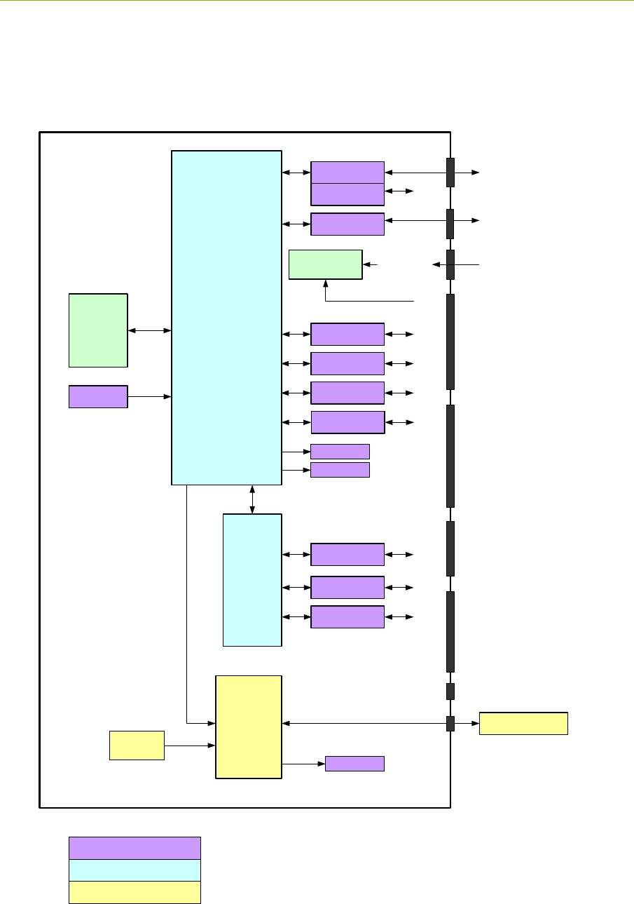
3 Hardware Block Diagram
This section provides and discusses at a high level the P330 functional hardware block diagram
shown in Figure 3-1. Additional detail on the various interfaces is provided in Section 4.
Fig. 3-1: P330 hardware functional block diagram
DW1000 RF Port A
Processor
FPGA
P330
UWB Antenna
Temp
Serial
USB USB Data Jack
Ethernet Jack
Ethernet
Can
J9
J5
Regulators
5-48Volts
Flash
and RAM
Memory
Blue LED
38.4MHz
Osc
USB Power Jack
SPI (5)
3.3V GPIO (3)
3.3V GPIO (3)
J10 User Mezzanine
- VCC_Main
- Power Enable
- Supply Ground
- Digital Ground
- SPI (5)
- Serial
- CAN
- ARM 3.3V GPIO (2)
- FPGA 3.3V GPIO (2)
J11 Locking Connector
- VCC_Main
- Supply Ground
- Digital Ground
- SPI (5)
- Serial
- CAN
- ARM 3.3V GPIO (1)
- FPGA 3.3V GPIO (3)
Power Enable
Ethernet RMII
J13
J8 Ethernet Mezzanine
- Digital Ground
- Ethernet
- ARM 1.8V GPIO (2)
- Ext 16MHz CLK (reserved)
1.8V GPIO (2)
1.8V GPIO (2)
J6 Factory Mezzanine
- Digital Ground
- FPGA 1.8V GPIO (2)
- ARM 3.3V GPIO (1)
- Factory Reserved
Chassis Ground
VCC_Main
Green LED
UWB Components
Non-UWB Component
User Interface
LEDs (4)

16 P330 Data Sheet / User Guide
DRAFT
The P330 requires less than a Watt of power from a DC supply that provides any voltage between 5.5
and 48 volts. This power can be provided through Time Domain’s standard external power supply, a
battery, or a user-supplied power source. Indicator lights provide operating status information.
The processor monitors and controls the DW1000, initiates range requests, controls the flow of data
to and from the DW1000, operates the network, computes locations and handles the interface with the
host/user.
The DW1000 is a full UWB transceiver. It transmits and receives packets, sends data, initiates Two
Way Time of Flight Range measurements and reports the range measurements as well as several
statistics related to the measurement.
The user can interface to the P330 through Ethernet, USB, SPI, Serial, or CAN. Ten GPIO pins are
available. If the SPI interface is not used, then these pins can be reassigned yielding an additional
five GPIOs for a total of 15.
In addition, the user can request that the P330 report the board temperature.
A variety of means have been provided to physically interface to the P330. These means include two
USB connectors, an Ethernet RJ45 connector, a locking connector, and three mezzanine connectors.
See Section 4 for details. The mezzanine connectors are suitable for mating directly with a customer-
provided board. Mating mezzanine connectors can be ordered with a variety of mated heights,
thereby allowing the user to mount low profile devices on their carrier board underneath the P330.
See Section 5 for details.
P330 Data Sheet / User Guide 17
DRAFT
4 Electrical Interfaces
This section provides a detailed description of the various P330 electrical interfaces. A standard P330
has the following connections:
One antenna port
Communications for Low Speed Serial, USB 2.0, Ethernet, CAN, SPI
Connections for up to 15 GPIO pins
Connections for power (5 to 48V), Ground, and Chassis Ground
There are also eight indicator LEDs, six on the board and two on the RJ45 jack.
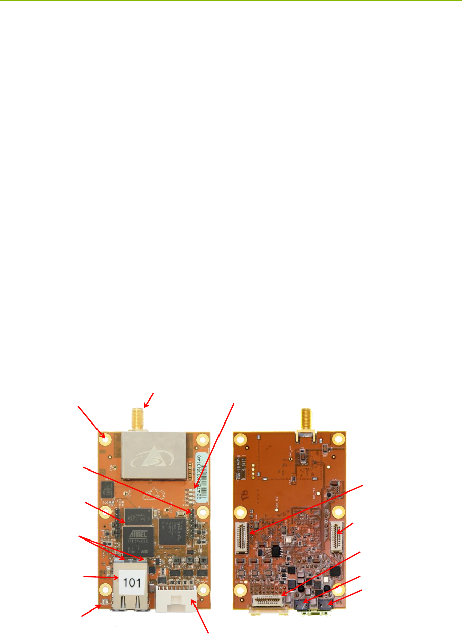
The physical interface to Communications, GPIO, and Power are through a mix of connectors (see
Figure 4-1) including the following:
Three mezzanine connectors
One locking connector
One Ethernet RJ45 connector
Two USB connectors (one power-only, one for data-only)
Two 0.1” DIP header, (one for the user and one for Factory checkout)
This arrangement provides the user with a maximum of flexibility for evaluating the technology and
demonstrating product proofs of concept. This flexibility of course comes with a monetary cost and
at some point in time the user will need to consider a stripped down implementation which provides
the required performance at a fraction of the cost. For further details on reducing the cost, contact
Time Domain directly at sales@timedomain.com.)
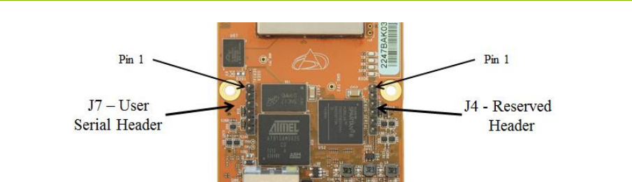
Fig. 4-1: Top and Bottom assembly drawing of the P330 highlighting key interfaces
Top Side Bottom Side
Chassis
Ground
J11- Locking
Ethernet Jack
with Kit
IP Address/Node Label
J10- User Mezzanine
J13- USB Power
J5- USB Data
J8- Ethernet Mezzanine
J6- Factory Mezzanine
J7 –User
Serial Header
J4 - Reserved
Header
Port A
UWB LEDs
Ethernet
LEDs
Signal LEDs

18 P330 Data Sheet / User Guide
DRAFT
Finally, the physical interface for the Chassis Ground is through the designated mounting screw hole
shown in Figure 4-1. (For additional details, see Section 4.3 – Powering and Grounding the Unit).
4.1 Connecting to the P330
The user can connect to the P330 in a number of different ways. For example, it is possible to:
Connect directly to the USB or Ethernet connectors
Build a special purpose cable and connect through the locking connector
Mount the P330 on a carrier board and communicate through one or more mezzanine
connectors
The following are examples of the electrical connections:
Option 1: USB. The user can connect to the board via the USB Data jack (J5) and power
the unit through the USB Power jack (J13).
Option 2: Ethernet. The user can connect to the P330 via the Ethernet RJ45 jack and then
power the unit through the USB Power jack (J13). Details on how the Ethernet IP address is
assigned can be found in Section 4.4.5 – Ethernet and IP Addressing.
Option 3: Locking Connector. The user can use the locking connector to connect via SPI,
User Serial, or CAN. This connector also provides power and ground. Details on the
pinouts for the locking connector and the part number for mating connector are provided in
the following section.
Option 4: User Mezzanine Connector. The User Mezzanine connector supports SPI, User
Serial, and CAN. It also provides power and ground. See the following section for details.
Option 5: Ethernet Mezzanine Connector. This connector provides power, ground, and all
of the Ethernet MAC signal lines necessary to communicate with the unit. However this
requires that the user provide an Ethernet PHY chip on a carrier board.
Several of these connection approaches offer access to the GPIO pins. See the following section for
details.
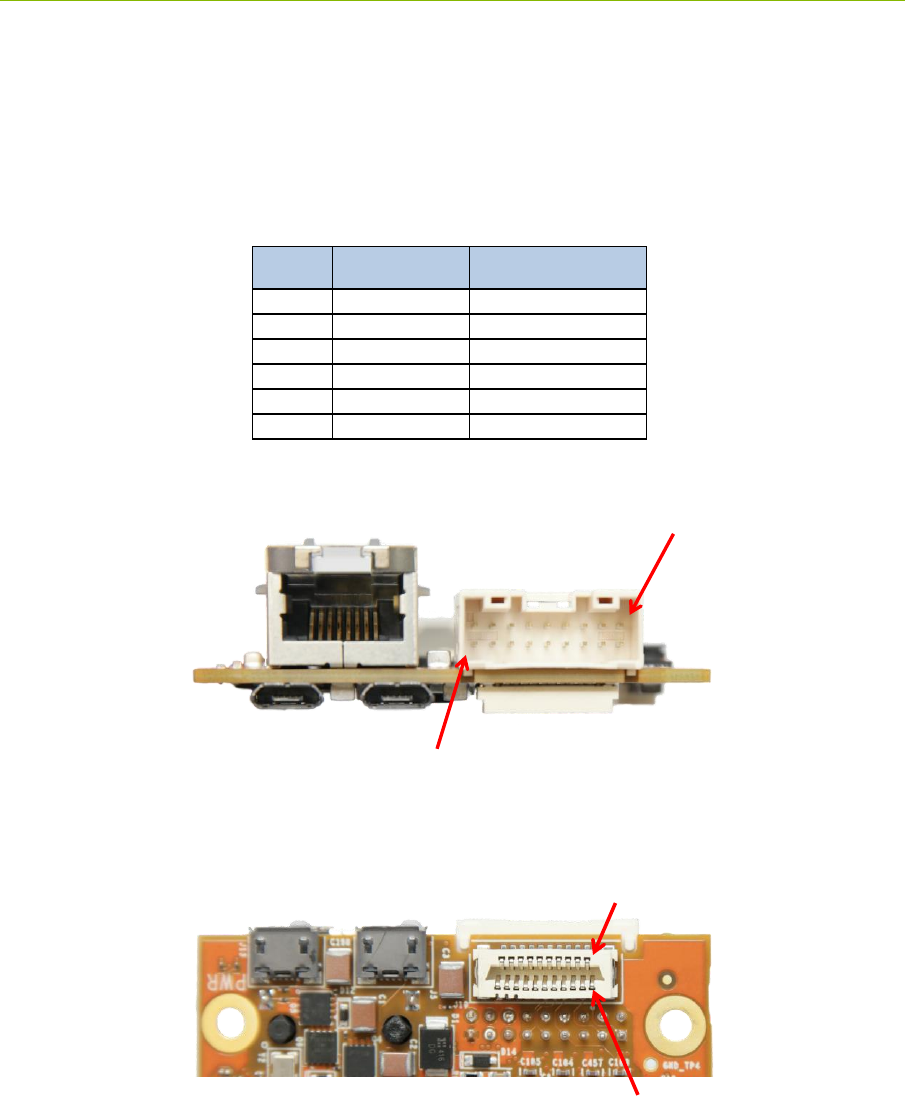
4.2 Connector Pinouts
The pinouts of the various connectors are shown in Figures 4-2, 4-3, 4-4, 4-5, and 4-6. The connector
pin numbering conventions are shown on Figures 4-7, 4-8 and 4-9.
All signal lines are provided with Electrostatic Discharge (ESD) protection (+/- 8 kV contact
discharge and +/-15 kV air-gap discharge). The signal line voltage levels are 3.3 Vdc, 1.8 Vdc, or (in
the case of CAN) are differential. These inputs are not tolerant to other voltages. Overdriving these
lines with too large a voltage or requiring them to source too much current will cause damage to the
P330. Please take care to avoid damage. Not only will this compromise or damage the performance
of the system but this class of damage is not covered by warranty.
Some of the mezzanine connector pins are marked as “Reserved.” The function of these pins may
change with time. If the user intends to mount the P330 on a carrier board, then it is advisable to
connect any pin marked “Reserved” to a landing point but to NOT connect the landing point to any
other trace on the carrier board.
The part numbers of all of the connectors and their mates can be found in Section 5 – Mechanicals.

P330 Data Sheet / User Guide 19
DRAFT
Finally, it may be useful to clarify the directions associated with the Serial transmit (TX) and receive
(RX) lines. “User Serial TX” means transmitted by the P330 to the Host. “User Serial RX” means
received by the P330 from the Host. All user serial lines operate at 3.3v.
Fig. 4-2: J11 - Locking connector
Fig. 4-3: J10 – User Mezzanine connector
Pin Name Function
1 SPI_MOSI SPI Master Out Slave In
2 SPI_INT SPI interrupt
3 SPI_MISO SPI Master In Slave Out
4 FPGA_GPIO_1_3.3V FPGA General Purpose IO #1, 3.3VDC
5 Digital Ground Digital Ground
6 FPGA_GPIO_2_3.3V FPGA General Purpose IO #2, 3.3VDC
7 SPI_CLK SPI Clock
8 Digital Ground Digital Ground
9 SPI_CS SPI Chip Select
10 User_Serial_TX User serial transmit
11 ARM_GPIO_0_3.3V ARM General Purpose IO #0, 3.3VDC
12 User_Serial_RX User serial receive
13 Supply_Ground Ground
14 Digital Ground Digital Ground
15 FPGA_GPIO_3_3.3V FPGA General Purpose IO #3, 3.3VDC
16 CAN_HIGH CAN differential high
17 VCC_Main Input Power
18 CAN_LOW CAN differential low
Pin Name Function
1 SPI_MOSI SPI Master Out, Slave In
2Digital Ground Digital Ground
3 SPI_MISO SPI Master In, Slave Out
4 SPI_INT SPI interrupt
5Digital Ground Digital Ground
6 FPGA_GPIO_1_3.3V FPGA General Purpose IO #1, 3.3VDC
7 SPI_CLK SPI clock
8 FPGA_GPIO_2_3.3V FPGA General Purpose IO #2, 3.3VDC
9 SPI_CS SPI Chip Select
10 Digital Ground Digital Ground
11 ARM_GPIO_0_3.3V ARM General Purpose IO #0, 3.3VDC
12 User_Serial_TX User serial transmit
13 Digital Ground Digital Ground
14 User_Serial_Rx User serial receive
15 ARM_GPIO_1_3.3V ARM General Purpose IO #1, 3.3VDC
16 Digital Ground Digital Ground
17 Power_Enable_H
Signal line to enable/disable on-board
regulators. This allows the user to turn power
to the board on and off with a single digital
control line. 0-2.1Vdc = off, 2.1Vdc to
VCC_Main = on
18 CAN_HIGH CAN differential high
19 Supply_Ground Ground
20 CAN_LOW CAN differential low
21 VCC_MAIN Input power (4.5 to 48v)

20 P330 Data Sheet / User Guide
DRAFT
SPI users should take note that the SPI interrupt line is pin 4 on the User Mezzanine and pin 2 on the
locking connector.
Fig. 4-4: J8 – Ethernet Mezzanine connector
Fig. 4-5: J6 – Factory Mezzanine connector
Pin Name Function
1 Digital_GND Digital Ground
2 E_Rx1 Ethernet Rx1
3 E_Rxer Ethernet Rxer
4 E_TxEn Ethernet TxEn
5 E_Tx0 Ethernet Tx0
6 Digital_GND Digital Ground
7 E_Tx1 Ethernet Tx1
8 E_CrsDv Ethernet CrsDv
9 Digital_GND Digital Ground
10 E_TxCk Ethernet TxCk
11 E_Rx0 Ethernet Rx0
12 Digital_GND Digital Ground
13 E_MDIO Ethernet MDIO
14 E_MDC Ethernet MDC
15 Digital_GND Digital Ground
16 Digital_GND Digital Ground
17 ARM_GPIO_0_1.8V ARM General Purpose IO #0, 1.8VDC
18 ARM_GPIO_1_1.8V ARM General Purpose IO #1, 1.8VDC
19 Digital_GND Digital Ground
20 Digital_GND Digital Ground
21 Ext_16MHz_In Reserved
Pin Name Function
1 Reserved
2 Reserved
3 Reserved
4 Reserved
5 Digital_GND Digital Ground
6 Digital_GND Digital Ground
7 Reserved
8 Reserved
9 Reserved
10 Reserved
11 Digital_GND Digital Ground
12 FPGA_GPIO_1_1.8V FPGA General Purpose IO # 1, 1.8VDC
13 Reserved
14 Reserved
15 Reserved
16 Reserved
17 Reserved
18 FPGA_GPIO_0_1.8V FPGA General Purpose IO #0, 1.8VDC
19 Reserved
20 ARM_GPIO_2_3.3V ARM General Purpose IO #2, 3.3VDC
21 Digital_GND Digital Ground
P330 Data Sheet / User Guide 21
DRAFT
The Factory Mezzanine connector has a number of GPIO pins and grounds which the user is free to
use. However the remaining lines are NOT available for use. All of these lines are active and are
used by the factory to test the unit as it moves through production. This connector can be used by the
customer but it is critical that the reserved pins should never be connected to any signal, ground, or
power lines. This can result in extreme damage to the unit.
Fig. 4-6: J7 – User Serial 0.1” Header
Fig. 4-7: J11 Locking connector pinouts
Fig. 4-8: J10 Mezzanine connector pinouts
Pin Name Function
1 Digital_GND Digital ground
2 No Connection Reserved
3 No Connection Reserved
4 User_Serial_RX User serial receive
5 User_Serial_TX User serial transmit
6 No Connection Reserved
17 15 13 11 9 7 5 3 1
18 16 14 12 10 8 6 4 2
20 18 16 14 12 10 8 6 4 2
21 19 17 15 13 11 9 7 5 3 1
22 P330 Data Sheet / User Guide
DRAFT
Fig. 4-9: J7 User Serial pinouts
4.3 Powering and Grounding the Unit
4.3.1 Powering the P330 through the USB Power Jack vs Locking &
Mezzanine Connectors
The P330 can be powered in three different ways: through the USB power jack, through the Locking
Connector or through the mezzanine connectors. The user should select one and only one means of
powering the unit. While it is physically possible to power the unit through all three means
simultaneously, this is a very bad practice and should be avoided. Connecting multiple power
sources at different voltages can result in damage.
Two different Grounds are provided: Digital Ground and Supply Ground. In principle Digital
Ground should be used for signal lines and Supply Ground should be used for main power ground. In
practice, the main value of the multiple ground lines is to guarantee a low impedance path to ground.
4.3.2 Reverse polarity protection
The power input (VCC_Main) is reverse polarity-protected and can be driven by any voltage between
5.0 and 48 volts.
4.3.3 Two means of Powering the P330
There are two techniques for supplying power to the P330. One can connect and disconnect the
power connectors or one can power the board continuously and use the Power_Enable_H pin on the
J10 User Mezzanine connector to turn on and off the P330 main power regulators. This capability
gives the user the opportunity to do a hard reboot of the P330 board without needing to physically
break a supply connection.
4.3.4 Chassis Ground
The P330 is provided with a chassis ground through one of the six mounting holes. Each of the six
mounting holes is copper plated on the top, bottom, and inside of the hole. The mounting holes are
not covered with silk screen. These holes are not connected to any ground planes or signals of any
sort. The one exception to this rule is connected to Digital_Ground through the parallel combination

P330 Data Sheet / User Guide 23
DRAFT
of a 0.01uF capacitor and 1.0 MegOhm resistor. This mounting hole provides the Chassis Ground.
The position of this hole is shown in Figure 4-1.
4.4 Host to P330 Interface Options
The P330 supports five different host interfaces: USB, Serial, SPI, Ethernet, and CAN. This wide
choice of interfaces provides the user with the freedom to experiment with and to optimize for their
specific application the means by which the overall system (P330 plus the user Host) communicates.
The characteristics of these interfaces are summarized below. For information on pin assignments see
Section 4.2 – Connector Pinouts.
The protocol used to communicate with the P330 is fully defined in the Time Domain RangeNet API
Specifications, various C and MATLAB examples, and in the document “Using the USB and Serial
specifications. All of these resources are provided on the delivery disks and are also available on the
Time Domain website, www.timedomain.com.
4.4.1 USB 2.0 High Speed Device
The P330 supports USB 2.0 High Speed Device connection through the USB Data microUSB jack
(J5). When connecting through J5 it is important to remember that this jack only provides the data
communications lines to the P330. To power the board, the user should apply power to the board
either through the USB Power microUSB jack (J13), through the locking connector (J11) or through
pin 21 on the User Mezzanine connector.
The maximum data rate for the USB is 480 Mbps. However, the maximum effective throughput will
be limited by many factors, including the speed of the Host computer, the specific implementation of
the USB driver, processing overhead at the P330, and processor overhead at the Host computer. The
effective transfer rate is on the order of 5-10% of the maximum data rate.
4.4.2 User Serial
The User Serial interface is RS-232 Universal Asynchronous Receiver/Transmitter (UART) Serial
link operating at 3.3V TTL logic levels. The maximum speed of the interface is 115.2 kbps. Lower
rates of 9.6, 19.2, 38.4, and 57.6 kbps are also supported. The default rate is 115.2 kbps.
However, the maximum rate is largely a function of the ability of the system to drive the cable
capacitance. If a shorter cable is used or if the user provides an external line driver, then the
communications rate can be increased by factors of 2 up to 921.6 kbps. Operation at these higher
ranges is also limited by the serial interface circuit on the user-provided Host computer. The
maximum length of cable must be determined empirically. Time Domain has found that a cable
length of 1 foot (30 cm) or less will support the 460.8 kbps rate quite reliably.
User Serial is provided on the Locking connector (J11), the User Mezzanine connector (J10), and the
User Header (J7).
The Serial interface uses 3.3 volt logic. Do not connect 5 volt serial cables to the P330. In fact, do not
connect any serial cables that operate at greater than 3.3 volts. The increased voltage will physically
damage the P330.
24 P330 Data Sheet / User Guide
DRAFT
While most users will connect to the serial port through either J11 or J10 doing so requires the
construction of a dedicated cable or interface. To use the serial interface directly, the user can
connect directly to J7 using a standard cable available from a number of sources including the
following:
FTDI (part number TTL-232R-3v3) or
Digikey (part number 768-1015-ND www.digikey.com).
4.4.3 SPI
The SPI interface is designed to operate at a maximum clock rate of 16.0 MHz with signals operating
at 3.3V TTL levels. The actual throughput of the link is limited by the various communications
overheads. However, transfer rates of 6-7 Mbps have been achieved using an un-optimized system.
The SPI interface allows the user to control the P330 with a co-located single board computer. Since
the operating speed of the link is subject to noise and line capacitance, the length of the SPI wiring
should be kept as short as possible. When operating the SPI interface at a maximum rate of 16Mhz,
the cable length should be no longer than a few inches (10-15cm). The exact length needs to be
confirmed empirically. If, for a given length of cable, the link experiences communications
problems, then the user should reduce the SPI clock rate.
The SPI port consists of five signals. Four of these are the typical SPI signals: CLK, CSn, MOSI, and
MISO, each with a 100k pull-up resistor to 3.3 V. The fifth signal (INT) is active-high and is used to
indicate that data exists in the slave output FIFO. The INT signal does not have a pull-up resistor and
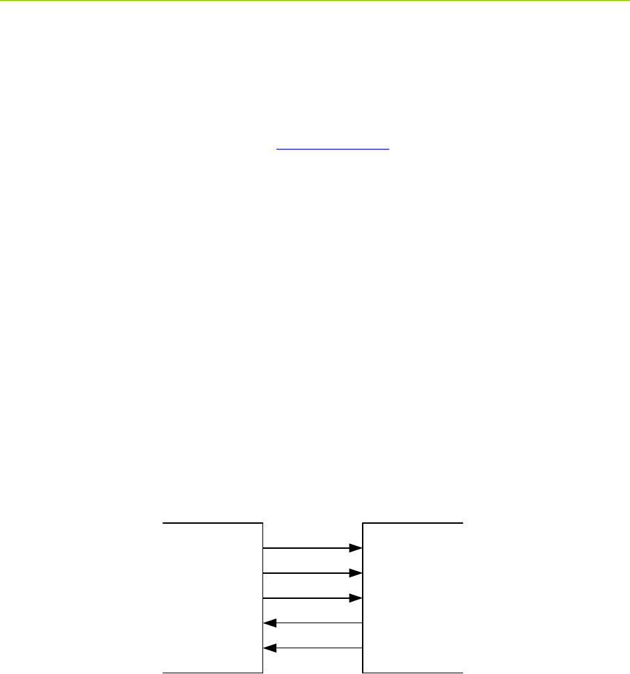
is not driven during initial power-up. The signals are illustrated in Figure 4-10. The SPI slave RX
and TX FIFOs are 4k x 8.
Fig. 4-10: SPI interconnect signals
The SPI port uses 8-bit bytes sent MSb first. The CLK idle state is high. The data is propagated on
the falling-edge (leading-edge) of clock and sampled on the rising-edge (trailing-edge) of clock as
shown below in Figure 4-11:
Master Slave
CLK
CSn
MOSI
MISO
INT
P330 Data Sheet / User Guide 25
DRAFT
CSn
CLK
MOSI
MISO 76543210
Bit 7 Bit 6 Bit 5 Bit 4 Bit 3 Bit 2 Bit 1 Bit 0 Bit 7
7
Bit 0
0
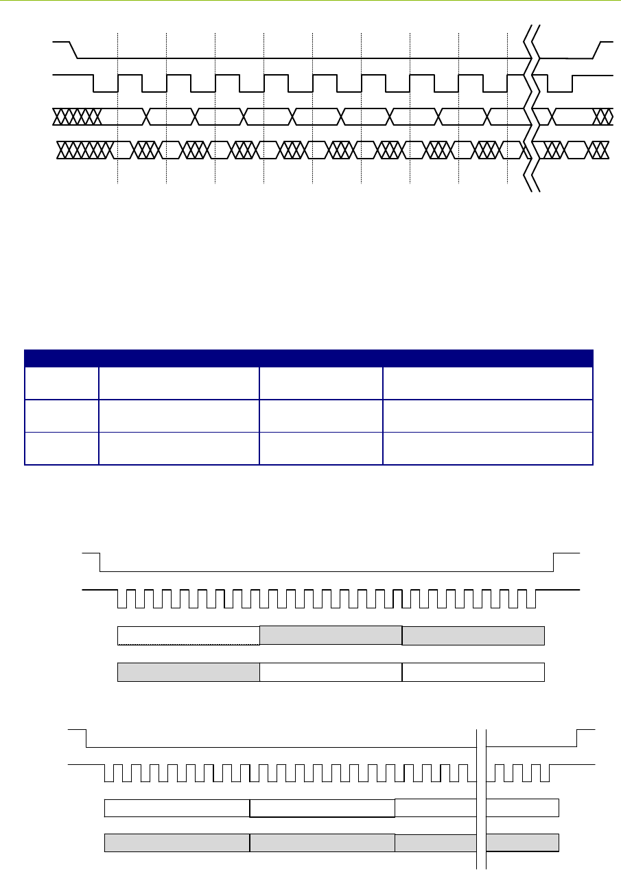
Fig. 4-11: Signaling timing diagram
The master drives the SPI chip-select low (CSn in above figure) and shifts an 8-bit command,
possibly followed by data. The first bit (MSb) of a command is always set. If the second bit is set,
then it is a read command, otherwise it is a write command. The commands are listed below in
Figure 4-12. The chip-select must stay active-low for the entire transaction, which is required to be
on 8-bit boundaries. This and other timing diagrams are shown in Figure 4-13. Timing constraints
are shown in Figure 4-14.
Command
Function
Command Format
Response Format
0x80
Write to slave input FIFO
Command
followed by data
N/A
0xC0
Read from slave output
FIFO
Command
Slave output FIFO data
0xC2
Read slave output FIFO
byte count
Command
Two bytes: MSB followed by LSB
Fig. 4-12: SPI command structure
CSn
Clk
MOSI
MISO
8-bit command (0xC2)
Response Byte 1 (MSB) Response Byte 2 (LSB)
Don’t Care Don’t Care
Don’t Care
Read slave output FIFO byte count
CSn
Clk
MOSI
MISO
8-bit command Data Byte 1 Data Byte 2
Don’t Care Don’t Care
Don’t Care
Write to slave input FIFO
Data Byte N
Don’t Care
Fig. 4-13: Timing diagrams
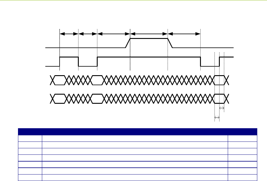
26 P330 Data Sheet / User Guide
DRAFT
CSn
CLK
MOSI
MISO
1 0 7
1 0 7
End of a SPI transaction Start of next SPI transaction
t1 t2 t3 t4 t5
t6
t7
Timing
Function
Minimum
t1
CLK high to CLK low (high pulse)
30 ns
t2
CLK low to CLK high (low pulse)
30 ns
t3
CLK rising-edge to CSn rising-edge (inactive)
50 ns
t4
CSn rising-edge (inactive) to CSn falling-edge (active) or time between transactions
60 ns
t5
CSn falling-edge (active) to CLK falling-edge
50 ns
t6
Data setup to CLK rising-edge
12 ns
t7
Data hold from CLK rising-edge
12 ns
Fig. 4-14: Timing constraints
4.4.4 Ethernet and IP Addressing
Ethernet 10/100 is provided either through the standard Ethernet RJ45 Jack or as Ethernet RMII
signal lines through the Ethernet Mezzanine Connector (J8). As such, the RMII signals cannot be
interfaced to directly. The user must provide a carrier board and an Ethernet PHY chip. The PHY
chip should be configured for Address 1.
The communications rate through this interface is limited not only by the Ethernet 10/100 protocol
but also by the processing capability of the connected computer and various system overheads.
The IP address of a unit is assigned in one of two ways. If the P330 came as part of a Development
Kit then the IP addresses will be set at the factory to 192.168.1.x, where “x” is indicated on a label
mounted on the P330’s RJ45 jack. If the P330 was ordered as an “Industrial Module” then the IP
address is normally set to 192.168.1.100. The RangeNet GUI gives the user the ability to change the
IP address or to select the Dynamic Host Configuration Protocol (DHCP). Upon special request and
in conjunction with volume orders, Industrial Modules can alternatively be shipped using DHCP.
As a side note, the Node ID of the P330 is set in a similar fashion. If the P330 came as part of a Kit
then the Node ID will be set to “x.” If the P330 came as an Industrial Module, then the Node ID is set
at the factory and can be determined through the API or the RangeNet GUI provided with the system.
When using the GUI, the Serial Number shown on the Status Info Tab will be identical in value to the
Node ID. However, the Status Info Tab shows the value in hexadecimal while the Node ID is shown
in decimal.
Instructions on how to connect to the P330 via Ethernet or change the IP address and Node ID are
provided in the documents 320-0338 P330 RangeNet User Guide.

P330 Data Sheet / User Guide 27
DRAFT
4.4.5 CAN
The CAN interface is provided with a TI SN65HVD231 CAN line driver. That driver provides a 5
volt differential signal. For additional details on the driver, a link is provided to the TI part. The
maximum data rate is 1 Mbps. http://www.ti.com/lit/ds/symlink/sn65hvd231.pdf
Time Domain’s application note 320-0326 CAN Interface Application Note provides additional
information on the software interface. This document is available on the Time Domain website.
4.4.6 Detection of Failures
When the P330 is powered, it will boot and execute a series of self-diagnostic checks. This process
takes approximately 10 seconds. At the end of this process the unit will respond to commands issued
by the Host. If the unit has failed to boot, then there will be no communications. If the unit has failed
self-diagnostics, it will set the “BIT Results” parameter to a non-zero number and attempt to function
normally. “Attempting” to function normally does not guarantee that the unit will actually function
properly. Therefore, it is a good practice for the Host computer to initiate communications with the
P330 by first checking the BIT Results. (This is accomplished with the Status Info Message. See the
API for details.) If the returned parameter is not zero, the unit should be power-cycled.
4.5 GPIO
The P330 has fifteen user-definable general purpose input/output (GPIO) pins. Most of these pins
operate on 3.3 Vdc but there are several that operate at 1.8 Vdc. Approximately half come from the
ARM processor and the remaining ones are connected to the FPGA. These pins can be defined as
inputs, outputs, or as having a special function. The SPI pins are special function pins. If the user
chooses not to use the SPI interface, then the SPI pins can be reallocated for general use. The state
and direction of these pins are controlled through the software API.
GPIO output pins can be used to source 1mA of current per pin. Do not exceed this limit. Exceeding
this limit will damage the P330.
The GPIO pins are not associated with a specific connector but are instead distributed through the
various connectors. Some GPIO pins are available from multiple connectors. Figure 4-15 lists the
various GPIO pins and their associated connector and pin number.
As of this date, there is currently no software support (i.e. API commands) for controlling the state of
the GPIOs. Similarly, the function of the SPI lines is currently fixed such that these lines can only be
used for SPI. Time Domain expects to provide expanded support for GPIOs in an upcoming
software release.

28 P330 Data Sheet / User Guide
DRAFT
Fig.4-15: GPIO and associated connector and pin locations
4.6 Antenna Port
The P330 has one antenna port. It is designated as Port A. The connector used is a standard polarity
female SMA connector (Digi-Key part number J801-ND).
When connecting the port to an SMA cable or antenna, be careful not to overtighten the connection.
This can cause damage to the board. Beware of loose connections. They can degrade performance.
As long as the connectors are “finger-tight,” the system will work well. To insure an optimal
connection, the user should use a calibrated SMA torque wrench. They cost <$100.
The P330 is intended to be used with Time Domain’s Broadspec antenna. Using any other antenna
will require recertification to confirm compliance with the relevant emissions regulations. However,
it is possible to add passive extension cables between the antenna port and the antenna. Be aware that
using alternate UWB antennas, additional fixed attenuators, additional cabling and/or connectors will
change the RF time-of-flight electrical distance between the antenna port and the phase center of the
antenna. Failure to account for such changes will result in a bias error in range measurements.
4.7 RF Transmit and Receive Characteristics
The RF transmit and receive characteristics are determined by the Decawave DW1000 chip. Given
that, the most logical source of detailed technical information on the DW1000 can be found in the
documents DW1000 User Manual and DW1000 Data Sheet. While these data sheets are posted on
the Time Domain website, the best place for the most recent information is on the Decawave website.
However, the DW1000 has a great many different settings. Since the standard was developed largely
before regulations were put in place, some of these settings are either unwise to use or offer marginal
utility. For example, some of the RF Channel band edges fall outside the legal limits. If used,
J11 - Locking
1 SPI_MOSI
2 SPI_INT
3 SPI_MISO
7 SPI_CLK
9 SPI_CS
4 FPGA_GPIO_1_3.3V
6 FPGA_GPIO_2_3.3V
11 ARM_GPIO_0_3.3V
15 FPGA_GPIO_3_3.3V
J10 - User Mezzanine
1 SPI_MOSI
3 SPI_MISO
4 SPI_INT
6 FPGA_GPIO_1_3.3V
7 SPI_CLK
8 FPGA_GPIO_2_3.3V
9 SPI_CS
11 ARM_GPIO_0_3.3V
15 ARM_GPIO_1_3.3V
J8 - Ethernet Mezzanine
17 ARM_GPIO_0_1.8V
18 ARM_GPIO_1_1.8V
J6 - Factory Mezzanine
12 FPGA_GPIO_1_1.8V
18 FPGA_GPIO_0_1.8V
20 ARM_GPIO_2_3.3V
P330 Data Sheet / User Guide 29
DRAFT
designers must add filtering to bring transmissions within legal limits. Furthermore, one of the high
band channels overlaps with 5.8 GHz making its use dependent on the absence of ubiquitous 1 watt,
5.8GHz WIFI. Also, the 900MHz bands offer little improvement over the 500MHz channels.
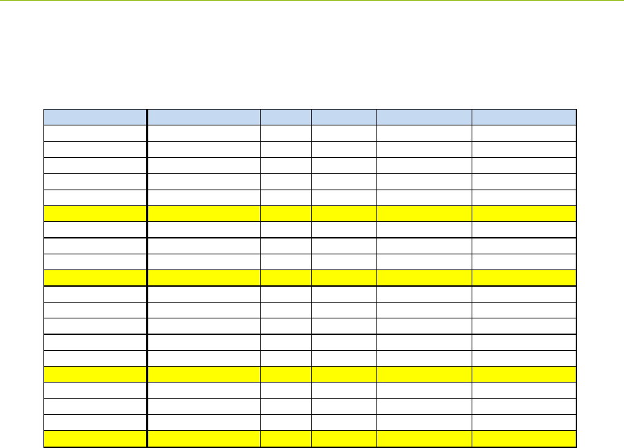
Therefore the P330 limits operation of the DW1000 chip to the 20 combinations shown in Table 4-1.
Table 4-1: DW1000 configurations supported by the P330.
These setting combinations are all in compliance with both the FCC and EU (ETSI) regulations. The
user has access to one additional DW1000 control and that is the transmit power. If the user accepts
the default P330 settings then the transmit power will be at or, slightly below, the regulatory limit.
The user also has the ability through the P330 API or GUI to set the transmit power up to 10db below
or above the regulatory limit. There are no issues with setting the transmit lower than the regulator
limit. Setting the transmit power to greater than the default value is useful in overcoming cable or
antenna losses and can be useful for development and evaluation purposes. However, using a higher
value (or using a different cabling or antenna combination) in a final product without recertification
for compliance with the regulations is expressly forbidden.
Of these, we have found that combinations highlighted in yellow are the most useful. They support
the largest number of communications channels and offer either the fastest ranging rate or the longest
operating range in both the high and low bands.
While Time Domain has found these 20 to be the most useful, we are open to increasing the number
of combinations supported if a compelling reason can be made for such additions.
4.8 Indicator Lights
The P330 is provided with eight indicator LEDs. See Figure 4-1 for exact locations. The following
is an explanation of the LED functions.
Ethernet LEDs (located on the back of the RJ45 connector)
Combinations RF Channel PRF Data Rate Preamb Length Preamble Code
1 2 (4.0/500MHz) 16 110 1024 3 or 4
2 2 16 850 256 3 or 4
3 2 16 850 512 3 or 4
4 2 16 850 1024 3 or 4
5 2 16 6.8 128 3 or 4
6 2 64 110 1024 9,10,11,12
7 2 64 850 256 9,10,11,12
8 2 64 850 512 9,10,11,12
9 2 64 850 1024 9,10,11,12
10 264 6.8 128 9,10,11,12
11 5 (6.5/500MHz) 16 110 1024 3 or 4
12 516 850 256 3 or 4
13 516 850 512 3 or 4
14 516 850 1024 3 or 4
15 516 6.8 128 3 or 4
16 564 110 1024 9,10,11,12
17 564 850 256 9,10,11,12
18 564 850 512 9,10,11,12
19 564 850 1024 9,10,11,12
20 564 6.8 128 9,10,11,12

30 P330 Data Sheet / User Guide
DRAFT
Green: Lit indicates operation at 100 Mbps, off means the link is operating at 10 Mbps.
Yellow: Lit indicates the link is available, flashing indicates activity, and off means no link.
UWB LEDs (located adjacent to the RJ45 connector)
Blue (Built in Test – BIT): flashing slowly (approximately 0.5 Hz) indicates that the unit is
operating normally. Flashing quickly (approximately 10 Hz) or solidly on or solidly off
indicates a failure.
Green (UWB activity): Toggles (if off, turns on – if on, turns off) as follows:
o On initiation of a Range or Network Request packet transmission
o On initiation of a Range or Network Response packet transmission
o On initiation of a Range or Network Data packet transmission
o On initiation of a Network Beacon transmission
The following is a description of the LED activity when the unit powers up. When power is applied
to the P330, the Green UWB LED will turn off and the Blue LED will turn on. The Blue LED will
stay on for approximately 8 seconds. During this time, the unit will boot and execute a Built in Test
(BIT) of the system. Once the unit has successfully booted and has passed BIT, then the Blue LED
will blink approximately every 2 seconds. Any behavior other than what is described above should
be considered to be a fault.
DW1000 LEDS (located adjacent to the barcode)
These LEDs (TX, RX, SFD and RXOK) are copied from and provide the same functions as the signal
LEDS found on the Decawave EVK. They have been included for the convenience of those users
familiar with operation of the EVK.
4.9 Heat Management
The P330 consumes approximately 1 watt. While this isn’t very much power, this energy is sufficient
to warm the board. In some extreme cases, this can cause issues. For example, if the board is
operated in a sealed enclosure, in a high ambient temperature, with solar heating then the resulting
thermal rise can raise the board temperature above its rated limit.
The P330 is equipped with a built in temperature sensor which will report the board temperature.
The user should monitor this temperature sensor and insure that the unit is not operated in excess of
the maximum rated temperature.
The following examples are provided to illustrate the effect of self heating on temperature rise.
Case 1: Ambient 23°C, bare P330 sitting on a table in still air. Board Temp: 34°C
Case 2: Ambient 23°C, P330 mounted in Time Domain enclosure accessory. Board Temp: 38°C
P330 Data Sheet / User Guide 31
DRAFT
4.10 Accessories
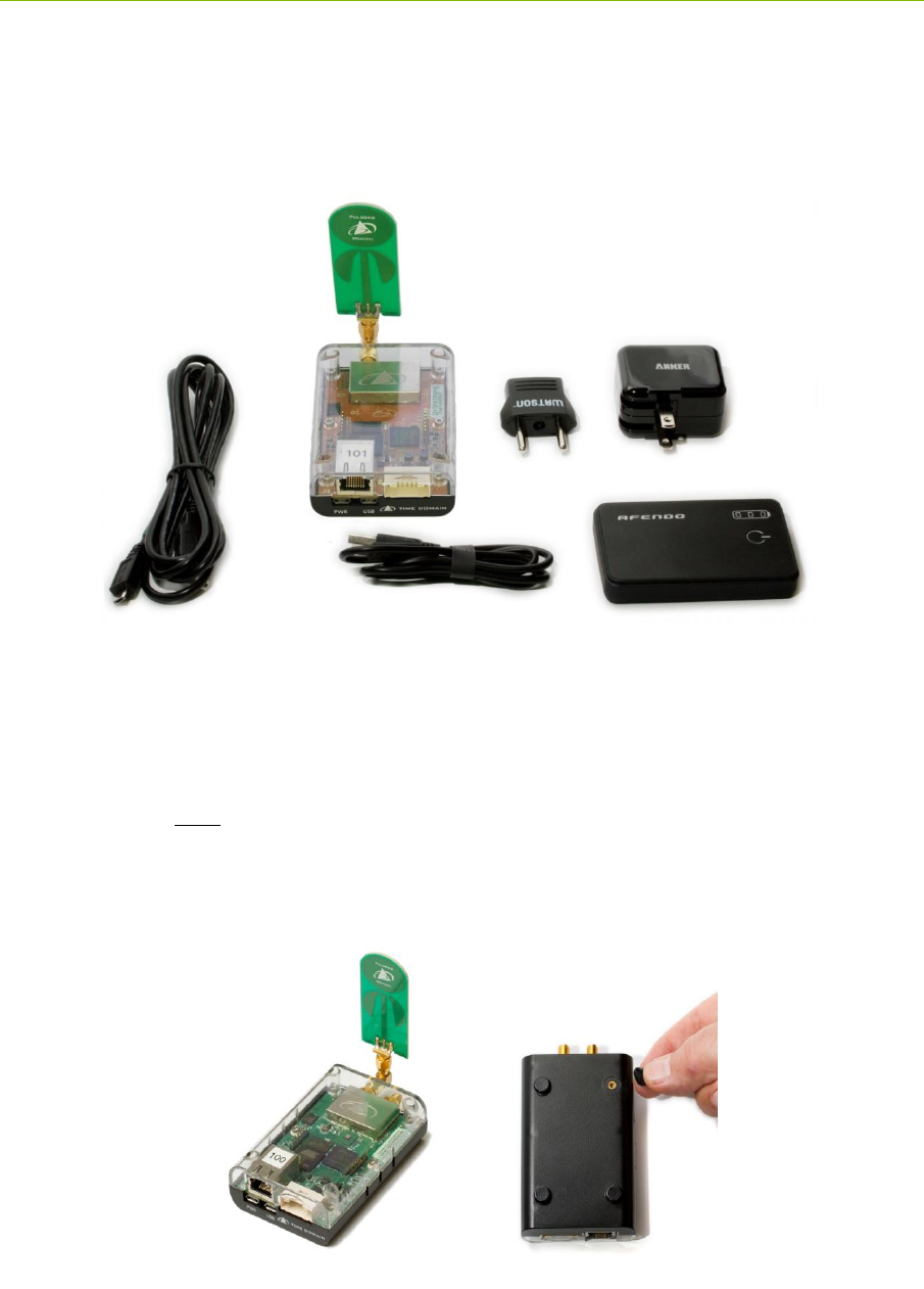
When the P330 is ordered as part of a Development Kit, it is provided with a number of accessories.
These accessories include: a custom plastic enclosure, a power supply, USB battery and cabling and
antenna. Units shipped outside the US are typically provided with a power plug adapter to ensure
compatibility with the user’s AC power plugs. This is illustrated in Figure 4-16.
Fig. 4-16: P330 with full set of accessories
4.10.1 Enclosure
The enclosure is intended to provide a modest level of protection for the boards. The primary goal is
to avoid damage from light handling, accidental drops on the floor, coffee spills, and the like. The
enclosures also make it easy to safely and conveniently take measurements in buildings and outdoors.
The enclosures are NOT waterproof or rain proof. A photo of the enclosure is shown in Figure 4-17.
Note that underneath the enclosure are 4 rubber feet which conceal four 4-40 (not metric) mounting
holes. Those holes are suitable for attaching the unit to a fixed object.
Fig. 4-17: P330 in standard enclosure (left) and view of enclosure bottom showing feet and
mounting holes for 4-40 screw
32 P330 Data Sheet / User Guide
DRAFT
4.10.2 Power Supply/Charger with Battery and Cables
P330s provided with Kits and Labs are normally powered through the USB Power jack. The easiest
(but not most reliable) way to communicate to the P330 is through the USB Data jack. Accordingly,
Time Domain provides each P330 with a USB Power Supply/battery charger, two USB cables (1.8 m
for communications and 15 cm for supplying power) and at least a 4000mAh USB battery. (USB
batteries change model numbers and capabilities almost continuously. As a result, the battery
provided with your kit may not be described in this data sheet, but it will drive the unit and supply at
least 4000mAh.
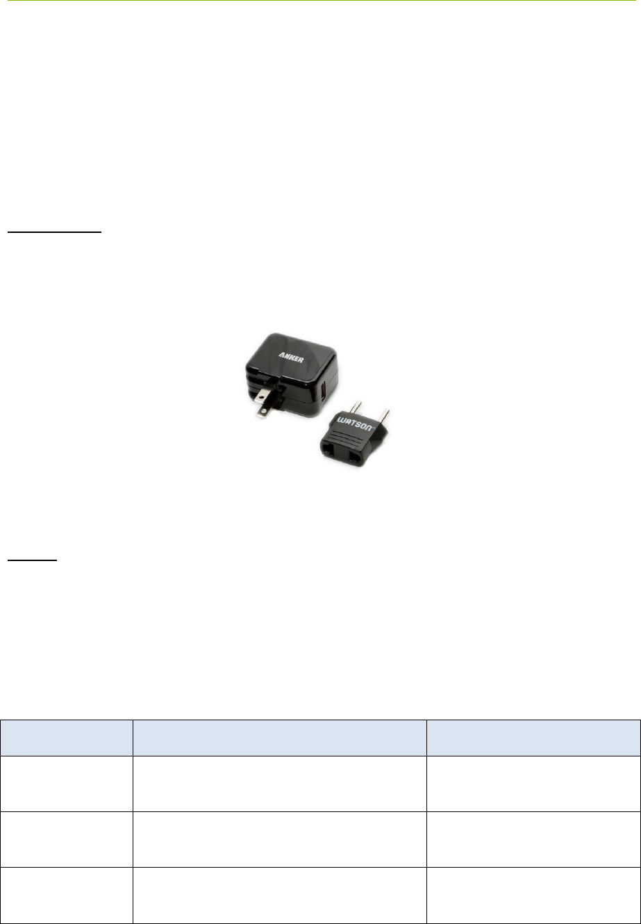
Power supply: The power supply is intended for use with the standard North American wall plugs.
For units shipped outside North America, the power supply is also provided with an interface plug
(see Figure 4-18). Every attempt is made to provide an adapter compatible with the end user’s
power system, but this cannot be guaranteed. Please indicate your preference when ordering your
equipment.
Fig. 4-18: USB Power Supply and interface plug
Cables: The 1.8 m (6 ft) cable is a standard USB cable and can be used to power the unit or
communicate through the USB data port. The 15 cm (6 in) cable is intended to connect the unit to
the USB battery but it can also support USB data communications.
In principle, there is nothing special about these components and they are almost universally
available. The user is free to provide substitutes and replacements for units that are lost or damaged.
While Time Domain does stock the USB battery all of these components are available on the web
from a variety of sources. Table 4-2 shown below provides source information for these
components. Where possible it includes specific suppliers and part numbers. Entering the product
description into your favorite internet search engine will lead you to any number of suppliers.
Description
Searchable description
Source and part number
USB battery
AFENDO 4000mah External Portable
Rechargeable Battery
6 ft/ 1.7 m USB
cable
6ft USB 2.0 A Male to Micro 5pin Male
28/28AWG Cable
Monoprice product number
12002
6 in /15 cm USB
cable
Premium USB to Micro USB Charge &
Sync Cable 0.5 ft –Black
Monoprice Product Number:
4868
P330 Data Sheet / User Guide 33
DRAFT
Charger/supply
Anker 10W (2A) Home and Travel USB
Wall Charger Adapter
Table 4-2: Accessory source information
WARNING: In practice, USB devices are not provided with a uniform level of quality. The devices
listed above work well and are recommended. The same cannot be said about other USB devices.
Some suppliers of cables use undersized wiring that is so small that it is not capable of providing
sufficient power to the P330s. Some produce power with a great deal of ripple. We have even seen
outputs with 1v spikes on a 5 volt signal! This is not acceptable for driving the P330s.
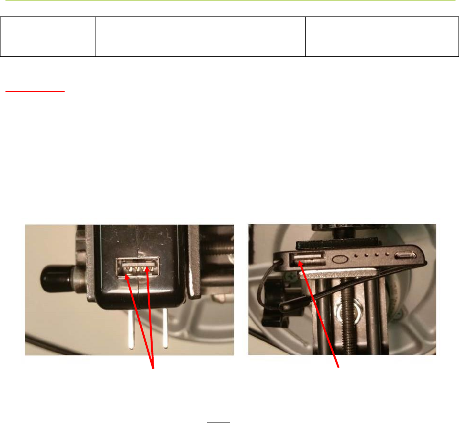
Some batteries and power supplies have very poor connectors. These connections are so flimsy that
they provide power only intermittently. Consider the devices shown in Figure 4-19. The connector
on the left provides a high quality connection with multiple contact points. The one on the right has
few contact points and will cause endless problems. Nothing will ruin a multiday measurement
campaign more completely than a few cheap, worthless USB cables and connections.
Fig. 4-19: Superior connections (left) and inadequate product (right)
When providing power from USB devices do NOT use USB extension cables. There is sufficient
voltage drop across these cables that they will not provide sufficient power to drive a P330.
Two sets of pins guarantee a good connection Nothing to insure a proper connection
34 P330 Data Sheet / User Guide
DRAFT
5 Mechanical Interface
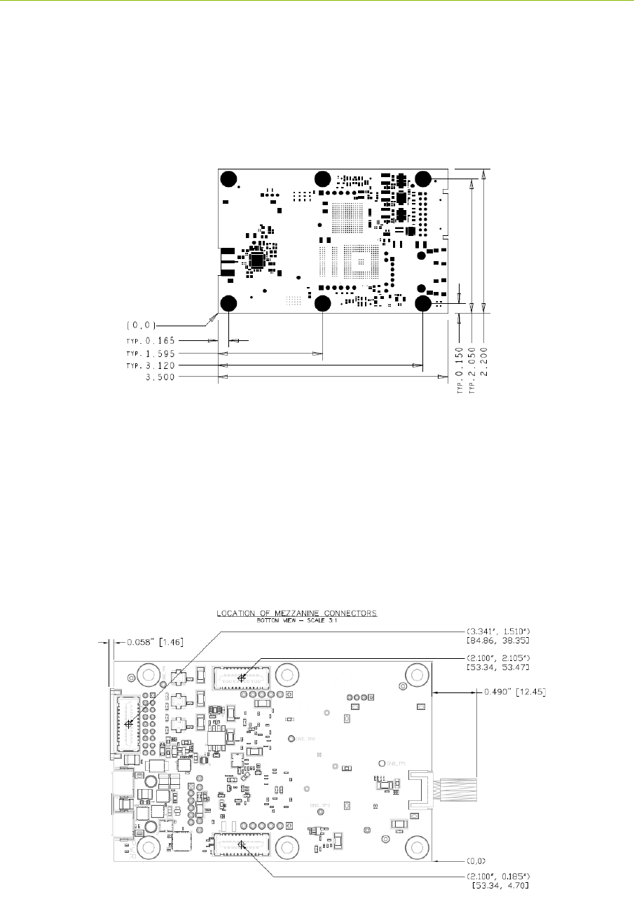
Figures 5-1, 5-2, 5-3, 5-4 and 5-5 provide the information which defines the board size, the height of
key components, as well as the location and dimensions of all connectors. Dimensions are shown in
British Imperial units (inches). Dimensions shown in [brackets] are in metric (millimeters). Table
5-1 lists the part numbers of all connectors and their respective mating pair.
Fig. 5-1: P330 board dimensions
The six mounting holes have an inside diameter of 0.125 inches (3.175 mm) and are sized for a #4
screw. The pads have an outside diameter of 0.250 inches (6.35 mm). The minimum distance
between the center of the hole and the closest component or circuit trace is 0.140” (3.556 mm).
It is anticipated that the number of mounting holes, size of the holes and placement separations are
sufficient to satisfy most vibration requirements. Several customers have already satisfactorily tested
the vibration performance of the P330 in extremely challenging end applications.
The P330 board is built to IPC Class 2 standards. The tolerances associated with hole size and
centering are consistent with this standard.
Fig. 5-2: Locations of Mezzanine connectors
P330 Data Sheet / User Guide 35
DRAFT
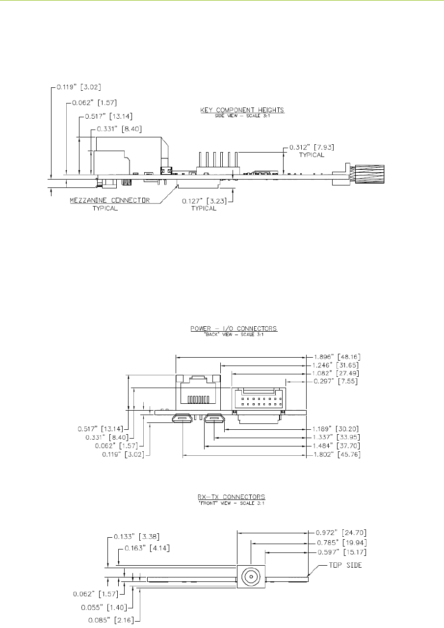
Shown in Figures 5-2 and 5-3 are all of the parts which extend out beyond the board dimensions.
This includes the RF SMA connectors, the Locking connector, the USB micro connectors, and the
RJ45 jack.
Fig. 5-3: Components which limit vertical height
When the P330 is mounted on a carrier board, the designer should be careful not to place any
components within 0.125” (3.17 mm) of the bottom of the board. This is a keep-out area and it is
reserved for components on the bottom side of the P330 board. Note that mating parts for the
mezzanine connectors are available with different lengths. By selecting a suitably tall mating
connector, the user can accommodate a wide variety of parts under the P330 without compromising
the keep-out area.
Fig. 5-4 Locations and dimensions of Power and I/O connectors at the rear of the P330
Fig. 5-5: Location and dimensions of RF SMA connector

36 P330 Data Sheet / User Guide
DRAFT
The part numbers for the P330 connectors and their mating pair are shown in Table 5-1.
Table 5-1: Connector part numbers
* These are standard SMA, USB, or 0.1” headers, for which the user has a very large number of
choices. The right choice is application-specific. Fortunately, there is an option for almost every
conceivable application.
Name and Number P330 Connector Part Number Mating Connector Part Number
J2 - SMA Port A
Cinch Connectivity# 142-0701-871,
Digikey# J610-ND
Many different choices. *
J5 - USB Data
FCI# 10103594-0001LF, Digikey# 609-
4050-1-ND
Many different choices. *
J6 - Factory Mezzanine
FCI# 91931-31121LF, Digikey# 609-
3520-2-ND
FCI# 91911-31321LF, Digikey# 609-
3424-2-ND
J7 - User Header
3M# 961106-6404-AR, Digikey#
3M9451-ND
Many different choices. *
J8 - Ethernet Mezzanine
FCI# 91931-31121LF, Digikey# 609-
3520-2-ND
FCI# 91911-31321LF, Digikey# 609-
3424-2-ND
J10 - User Mezzanine
FCI# 91931-31121LF, Digikey# 609-
3520-2-ND
FCI# 91911-31321LF, Digikey# 609-
3424-2-ND
J11 - Locking
JST Sales America: S18B-PUDSS-
1(LF)(SN), Digikey# 455-2490-ND
JST Sales America: PUDP-(18)V-S,
Digikey# 455-2473-ND
J13 - USB Power
FCI# 10103594-0001LF, Digikey# 609-
4050-1-ND
Many different choices. *

P330 Data Sheet / User Guide 37
DRAFT
6 Technical Specifications
6.1 Summary of Key Performance Parameters
Table 6-1 summarizes the P330 specifications and key performance parameters. For additional detail
on the performance of the DW1000 UWB chip see Decawave’s DW1000 User Manual and Data
Sheet. Note that the P330 uses a subset of the DW1000 RF channels. For a discussion on which
channels were implemented see Section 4.7 RF Transmit and Receive.
P330 Specs
Value
Physical Parameters
Board Dimensions (without SMAs):
3.5 x 2.2 inches (89 x 56 mm)
Assembly height (bottom to top
connectors):
0.703 inches (17.9 mm)
Weight:
1.6 ounces (45 grams)
Storage Temperature:
-40oC to 85oC
Operating Temperature range:
Industrial units:
-40oC to 85oC
Max allowable board temperature:
85c as reported by on board temp sensor
Humidity:
Up to 95%, non-condensing
Vibration:
Designed to meet most vibration specs. Existing
customers have already tested the P330 for operation in
extreme vibration environments.
Power & Ground & Boot Times
Input Power Range:
5.0 V to 48 V DC
Input Power Ripple:
100 mV pk-pk
Power Protection:
Reverse voltage
Electrostatic Discharge Protection:
+/-8kV contact discharge and
+/-15kV air-gap discharge
Chassis Ground:
Available. See Section 4.3.4 for details
Time from power on to completion of
boot:
11 seconds (no cables connected, with Serial connected
or USB connected, or no cables connected)
7 seconds (Ethernet connected)
Minimum time the power must be
turned off to force the processor to reboot:
1 second
Power & Temperature when Operating
as a Ranging Radio
Typical Power Consumption (board
temp 40oC, Vin= 5.0 V with state
transition times shown)
- Active (transmitting)
- Active (receiving)
- IDLE, Standby_E, Standby_S
1.0 Watts
1.0 Watts
0.5 Watts (Enter: 1.2 ms, Exit: 1.2 ms)
Operating Temp at ambient 23oC:
- On flat surface, receiving, no air
34oC (11o over ambient)

38 P330 Data Sheet / User Guide
DRAFT
circulation
- In Time Domain standard enclosure
38oC (15o over ambient)
User Interfaces/Devices
USB:
USB 2.0 Client – Micro-B connector
Maximum rate: 480 Mbps
See Section 4.4.2 for more details
Serial:
3.3V TTL Serial UART (8, n, 1) 115.2kbps (typical)
921.6kbps (over short, ~15cm cable)
See Section 4.4.3 for more details
Ethernet:
10/100
See Section 4.4.5 for more details
SPI:
3.3V TTL levels
16Mbps maximum clock rate
See Section 4.4.4 for more details
CAN:
See Section 4.4.6 for details
GPIO available:
3 Processor GPIO pin (3.3V)
2 Processor GPIO pin (1.8V)
8 FPGA GPIO pins (3.3V), 5 of which can be used
for SPI
2 FPGA GPIO pins (1.8V)
See Section 4.5 for more details
On Board Temperature Sensor:
-40oC to 125oC, +/- 2.0oC
RF Characteristics
Transmit Operating Band:
Chan 2 (4.0GHz center, 500MHz bandwidth) and
Chan 5 (6.5GHz center, 500MHz bandwidth)
Average Transmit Power:
Max power spectral density: -41 dBm/MHz
(This spectral density equates to approximately ~50 uW
or -13 dBm with an adjustability range: ~ -33 to -13
dBm)
Receive Sensitivity:
At 110Kbps:
At 6.8Mbps:
- 95 dB
-105 dB
Antenna Port
Standard 50 Ohm SMA coaxial
Antennas Supported:
Compatible with Time Domain BroadspecTM Toroidal
Dipole Antenna (0 dB) as well as a wide variety of 3rd
party antennas. Standard 50 Ohm SMA coaxial
connector
Communications
Channels per RF channel:
2 channels at PRF 16MHz, 4 at PRF 64MHz
Data Rate supported:
110,850, 6800 Kbps
Preamble Lengths:
128, 256, 512, 1024
Communications Type:
Packet transmission
Ranging Performance
Ranging Techniques:
Pulsed Two-Way Time-of-Flight (TW-TOF)

P330 Data Sheet / User Guide 39
DRAFT
Two-Way Time-of-Flight
Max Range:
30-400 meters (See Section 6.2)
Precision (3 Standard Deviations)
10.0 cm (See Section 6.4)
Unit to Unit bias error (uncalibrated):
~30 cm (See Section 6.4)
Bias error (-40 to 85) (uncalibrated):
~20 cm (See Section 6.4)
Bias error (if fully calibrated):
+/-2cm (See Section 6.4)
Range Measurement Rate
20-182 Hz (See Section 6.3)
Table 6-1: P330 performance characteristics
From time to time changes will be made to the P330 design. Section 6.8 describes how the version
number of any given board can be determined and describes the version to version differences.
6.2 Maximum Operating Range of a P330 Radio
Operating range in any given application will be a function of parameters the user can control and
ones that are beyond control. Controllable parameters include transmit power (normally set to the
maximum value that the regulations allow), the antenna height, and the RF channel/message
configuration parameters (such as PRF, data rate and preamble length). The channel and parameters
are usually set either for maximum ranging rate (which provides a shorter operating range) or the
maximum operating range (which results in a slower ranging rate).
Parameters which affect range but which are not controllable include blockages from RF reflective or
impenetrable structures and attenuation due to propagation through foliage and walls. Interference
from other RF systems operating in the area is also a possibility but in practice it rarely happens.
While all of these factors are well understood (if not obvious) the most important parameter to
consider (and the one most frequently overlooked) is constructive and destructive Fresnel cancellation
and enhancement.
Section 6.2.1 will describe why Fresnel is such an important factor and Section 6.2.2 will offer
empirical data to illustrate operational range performance and Fresnel effects under a wide variety of
conditions.
6.2.1 Fresnel – Key Limit to Operational Range
Basically, when operating over open ground, transmissions will be received from the direct path as
well as from the forward scattered reflections from the ground. Since the ground reflection will
arrive at the receiver a bit later than the signal following the direct path, the summation of the two
signals can be either destructive or constructive. Destructive cancellation can be so severe that at
some separation distances the signal will not be received. At some distances constructive interference
will significantly increase the received signal, in which case the operating range will be increased. At
other distances the delay time between the two signals could be so large that neither has a meaningful
effect on the other.
While the Fresnel effect is frequently overlooked, in most outdoor applications it will be the primary
factor limiting the operating range. To illustrate this phenomenon consider Figure 6-1. In this
example, two radios were placed approximately 1.7 meters above the ground and data was taken
while the distance between the units was increased. The first unit was mounted on a tripod and the
second mounting above the roof of a small car. The test started with a separation distance of 8 meters
and the car slowly drove off until the signal disappeared. Figure 6-1 shows the results as a plot of
First Path Power (a measure of the received signal strength) as a function of the distance.
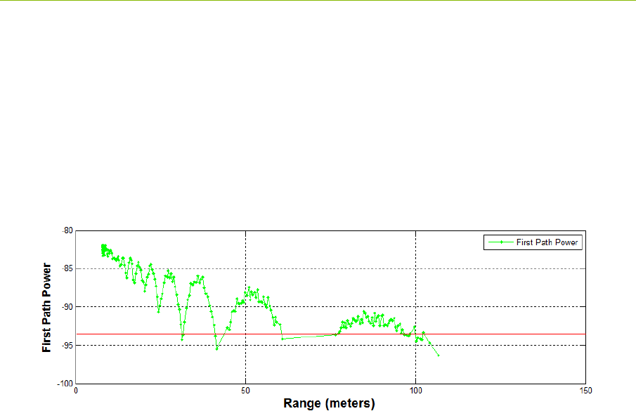
40 P330 Data Sheet / User Guide
DRAFT
There are several items to note. First, the received signal has serrated look. Every 5-10 meters the
signal strength diminishes. As the separation distance increases the spacing between minima
increases. At the same time the depth of the minima also increases. These serrations are destructive
cancellation due to the Fresnel effect.
Second, at some point the received signal strength will drop to the point that the receiver will not be
able to acquire. For these settings (RF Channel 5, 64 MHz PRF, preamble length of 64 and 6.8Mbps)
will link failed at -94dB. This level is indicated by the red line.
Finally, the -94dB value that defines the location of this red line will vary from unit to unit by a few
dB. A prudent system designer will incorporate additional margin to insure that all of the units will
meet the system operational requirement.
Fig. 6-1: Plot of received signal strength (First Path Power) vs separation distance (range in
meters)
Defining a maximum operating range is ambiguous. While it is clear that ranges were measured out to
100m, it is equally clear that no range measurements were possible between 60 and 75m. In fact, the
signal was marginal at 30 meters and again at 40 meters. Depending on the requirements of the
application, the correct specification for maximum operating range could be anything from 30-100
meters, perhaps less if an allowance for margin was added. The correct answer for most applications
is probably 65 meters, but users who need a higher quality of service would argue for 30 meters.
It is also possible to mitigate the Fresnel effects at the cost of increasing the complexity of the overall
system. For example, assume it is necessary to monitor the location of many units as they move
through a fixed area. Furthermore, assume that the location of the units is determined by measuring
their distance to a set of fixed references mounted on the walls of the area. Since the Fresnel effects
are largely due to geometry, their effects can be mitigated in several ways. First, the infrastructure of
fixed references could be doubled such that all units would have at least three references which were
not at ranges that corresponded to Fresnel minima. Second, the fixed infrastructure could be outfitted
with multiple antennas each a different height. This would change the geometry such that one
antenna would be affected by the a Fresnel while the second could be counted on to have an
acceptable signal.
It becomes more difficult to define a maximum operating range if the units in the link are also
allowed to vary their height. In this a case, the location of the Fresnel nulls will move quite
dramatically. Suppose you were designing a system for tracking the location of miners in an open
area. Suppose further that the location tag was mounted on the miner’s helmet. In this case, the
location of the Fresnel nulls would be considerably different between tall miners and short ones. The
Fresnel nulls would change if any miner sat down or climbed on a tall vehicle.
While this can get complicated, the goal of this section is not complication. The objective is to
illustrate this phenomenon in a way that a system engineer can understand the issue and work to
define an appropriate solution. One approach is to require that the operating distances to limited to a
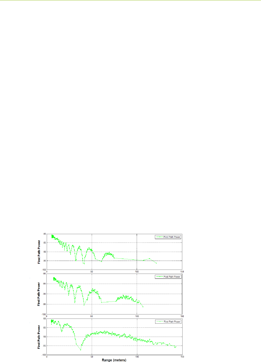
P330 Data Sheet / User Guide 41
DRAFT
very short value, in this case, to less than 30 meters. Another approach would be to add a significant
number of references to the system. Intermediate solutions are also possible. But failing to consider
propagation performance in the system design will result in a very unhappy customer.
6.2.2 Examples of Operational Range
The figures in this section illustrate operational performance of distance of 4 standard radio
configurations for each of three deployment scenarios. These figures are followed by a table
summarizing performance.
The four standard configurations are:
RF Channel 5 (High Ranging Rate) PRF 64M, Preamble 128, Data Rate 6.8Mbps
RF Channel 5 (Low Ranging Rate) PRF 64M, Preamble 1024, Data Rate 110kbps
RF Channel 5 (High Ranging Rate) PRF 64M, Preamble 128, Data Rate 6.8Mbps
RF Channel 5 (Low Ranging Rate) PRF 64M, Preamble 1024, Data Rate 110kbps
The three scenarios are
1.7m to 2.3m (tag mounted on a person’s helmet or on a robot to a wall mounted reference)
1.7m to 1.7m (tags mounted on helmets)
1.0m to 1.0m (tags on pallets or attached to a person’s belt).
Performance statistics are shown in Red in the lower right hand corner of the following figures. The
values to the left of the / indicate the range of values for the minimum and maximum reliable
operating range while the number to the right indicates the maximum range achieved. These are
subjective values based on the author’s opinion. The reader is encouraged to consider this data in the
context of a specific application and suggest better values.
As a side note, the Matlab used to collect and produce these figures is provided with the equipment
and can normally be found on the Time Domain website.
Fig. 6-2: RF Channel 5 (High Ranging Rate) Received Signal Strength vs Range for 3 scenarios
1.0 –1.0 m
1.7 –1.7 m
1.7 –2.3 m
30-60m / 120m
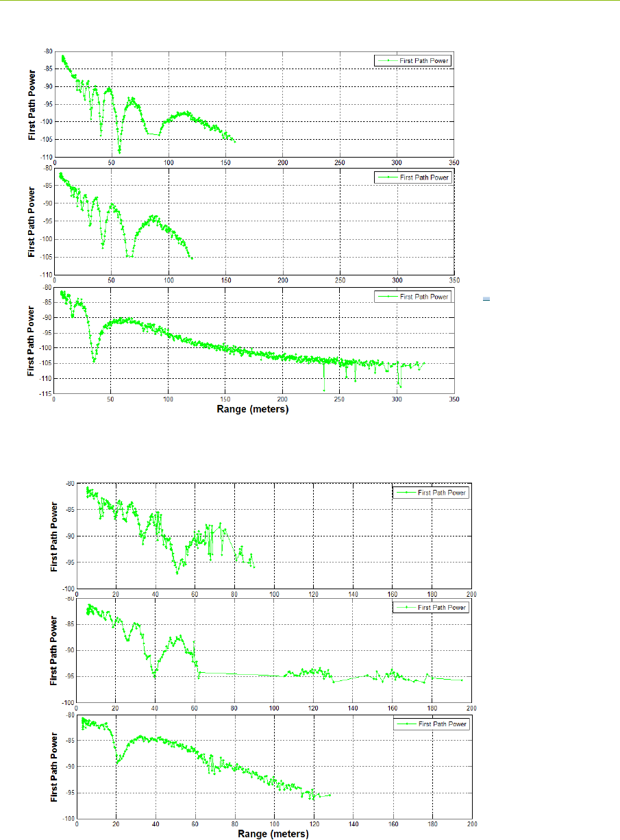
42 P330 Data Sheet / User Guide
DRAFT
Fig. 6-3: RF Channel 5 (Low Ranging Rate) Received Signal Strength vs Range for 3 scenarios
Fig. 6-4: RF Channel 2 (High Ranging Rate) Received Signal Strength vs Range for 3 scenarios
1.0 –1.0 m
1.7 –1.7 m
1.7 –2.3 m
60-100m / 230m
1.0 –1.0 m
1.7 –1.7 m
1.7 –2.3 m
40-60m / 120m
P330 Data Sheet / User Guide 43
DRAFT
Fig. 6-5: RF Channel 2 (High Ranging Rate) Received Signal Strength vs Range for 3 scenarios
These results are summarized in the following table.
Table 6-2: Maximum Operational Range for 4 radio configurations
6.3 Range Measurement Rate
Ranging Conversation Time is the amount of time required to take a single TW-TOF range
measurement. The maximum measurement rate is limited by the Host to P330 overhead conversation
time required to initiate a range request. This overhead will limit the measurement by approximately
30% of the values shown in the table below. This overhead is eliminated when the range requests are
handled through RangeNet.
The Maximum Range Measurement Rate is shown in Table 6-3 and is achieved when two radios
are operated as a network consisting of a single requester unit and a single responder unit.
1.0 –1.0 m
1.7 –1.7 m
1.7 –2.3 m
60-100m / 300m
RF Channel Low Rate (Max Range) High Rate
Chan 2
(Low band) 60-100/300 40-60/120
Chan 5
(High band) 60-100/230 30-60/120

44 P330 Data Sheet / User Guide
DRAFT
Table 6-3: Ranging performance characteristics at maximum legal transmit power
6.4 Range Measurement Precision, Bias and Accuracy
The Range Precision, Accuracy and Bias are defined by the performance of the Decawave DW1000
chip all of which is described in the Decawave product documentation. For more detail, the reader is
encouraged to review the product information provided by Decawave.
This section will focus on discussing the precision, accuracy and bias of the DW1000 based on
empirical data and experience gathered to date.
6.4.1 Precision in LOS and NLOS Conditions
The DW1000 has a precision (standard deviation) of 10cm. This is a 3 sigma value and has been
verified both in a lab environment and in the field. Note that this is a line of sight measurement and
it assumes that the antennas of the units are clearly visible to each other that there are no obstructions
or partial blockages of the direct path and that is very little reflective surfaces which will cause
“undo” amounts of multipath. These conditions are typical of operation outdoors and are also typical
inside large areas inside building.
Operating inside buildings frequently requires transmissions through walls as well as operation in the
presence of significant reflectors. These factors will attenuate and distort the signal in a variety of
ways that will compromise the precision and bias of the resulting readings. This degradation is
generally modest, largely because serious degradation will normally be significant enough to prevent
a link from being completed. For logistical reasons, it is very difficult to quantify this degradation
especially over a wide enough number of RF environments to be statistically significant. Even so,
one can expect the precision to be generally acceptable and consistent with the chip specification.
6.4.2 Precision in Fresnel Nulls
Bal blah blah blah
6.4.3 Bias and Calibration
The DW1000 does not report range measurements with a bias of zero. This is to be expected
because the bias is a function various electrical delays in the chip, on the board, in cabling to the
antenna and in the antenna itself.
This bias needs to be calibrated out and a procedure for doing so is described in the RangeNet User’s
Guide.
The user can expect each unit to have a different bias error. The variation for most of the units is
Configuration:
Chan 2 (low band) or 5 (high band), PRF=64MHz,
Preample (128 or 1024), Data Rate = (110KHz or
6.8Mbps)
Range Conversation Time
(milliseconds)
Maximum Range
Measurement Rate (Hz)
Chan 2: High Rate (64MHz, 128, 6.8MHz) 5.5 181.8
Chan 2: Low Rate (64MHz, 1024, 110KHz) 48.0 20.8
Chan 5: High Rate (64MHz, 128, 6.8MHz) 5.5 181.8
Chan 5: Low Rate (64MHz, 1024, 110KHz) 48.0 20.8
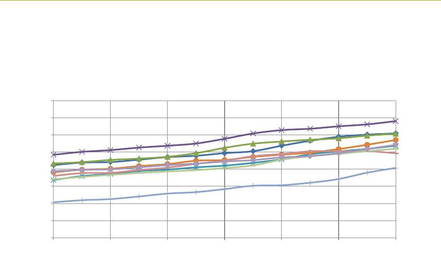
P330 Data Sheet / User Guide 45
DRAFT
approximately 150mm although it is not unusual to find individuals which are different by more than
300mm. It is also important to note that the bias also varies over temperature. Furthermore, this is
slightly nonlinear and even with a single order compensation, the user can expect residual bias errors
on the order of +/- 2 to 3 cm.
An example of bias performance over temperature of nine units is provided in Figure 6-6 below.
Fig. 6-6: DW1000 Bias performance over temperature.
While bias calibration is relatively straightforward it is very important that it is handled appropriately.
If not, then the user will experience significant errors when attempting to localize.
Decawave’s documentation and application notes provide several suggestions as to how these
changes in bias with temperature can be best accommodated.
Once Time Domain has completely characterizes the behavior of a few hundred units, it is our
intention to provide temperature compensated range measurement. In the meantime, the P330
provides the user with a means of measuring the board temperature. This allows the user the
opportunity to implement a temperature compensation routine.
6.4.4 Accuracy
Range accuracy is a function of precision and bias. If ranges are used to determine location, then the
location accuracy will be a function of the accuracy of the constituent range measurements. To a first
order, the accuracy of the DW1000 will be approximately 5-10cm. For many applications this will be
more than sufficient.
For applications that require more accuracy, it will be necessary to do a more complete analysis.
Such an analysis would include evaluation of the environment in which the equipment is to be used,
determination of the maximum rate at which a P330 would move, and consider the effects of
averaging. Basically, a “bad” environment and “fast” moving mobiles will degrade accuracy. On
the other hand, most errors are Gaussian so any form of averaging will improve accuracy. Averaging
can be the result of taking many range readings on a particular link and averaging them over time or it
could come in the form of taking many range readings to a large infrastructure of anchors (reference
units). Other forms of averaging are also possible.
Finally, the accuracy and reliability of a system can be greatly increased if the system relies on the
combined outputs of multiple types of sensors. For example, integrating measurements from a UWB
ranging, inertial sensors and, if the device is a robot, wheel odometry will greatly improve the overall
system performance.
15.0000
15.1000
15.2000
15.3000
15.4000
15.5000
15.6000
15.7000
15.8000
-40 -20 0 20 40 60 80
Meters
Temp C
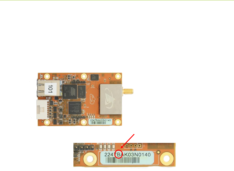
46 P330 Data Sheet / User Guide
DRAFT
6.5 P330 Revisions and Differences
From time to time slight changes or improvements are made to the P330 design. This section
explains how the user can identify the revision level of any P330 device and provides a location for
listing the differences between one revision level and another. This is also where any documentation
errors will be reported.
Version/Revision Level: The version or revision level of any given P330 is indicated in the bar
code of that particular P330 (See Figure 35 below).
Fig. 6-7: P330 Version indicated in bar code. Unit shown is a Rev B board.
To be more complete, the number 2247BAK03N0055 in the example shown above can be decoded as
follows:
2247: board type
B: board revision
A: board sub version
K: year of manufacture (for example J = 2015, K = 2016)
03: week of the year assembled
N: contract house
0140: serial number.
Note that when the user electronically polls the unit for its serial number, the returned value will be a
multi-digit number. These two values are linked in such a way that any board can be referenced by
either number.
Differences from previous versions: The B revision of the P330 is the first generally released
version. Had there been a previous version, then differences, improvements and corrections would be
summarized here.
Rev B board
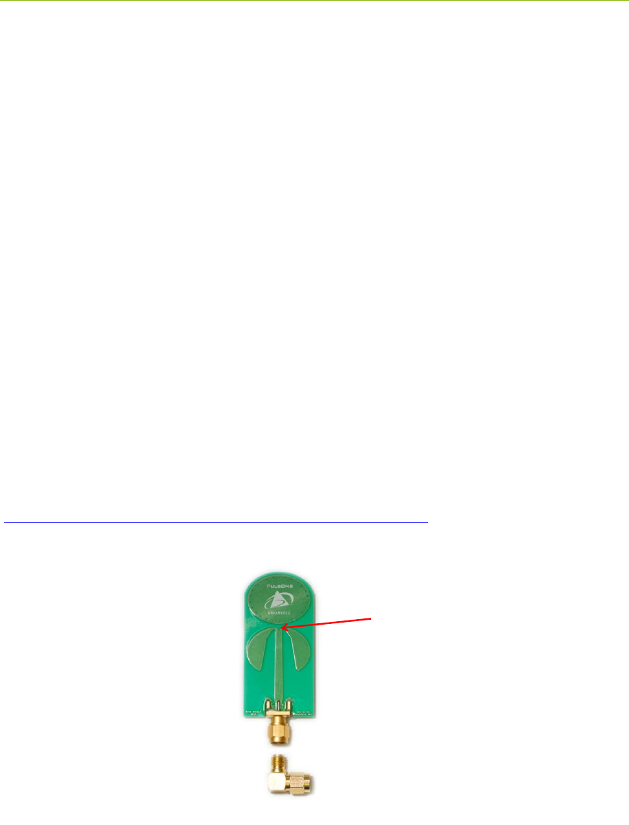
P330 Data Sheet / User Guide 47
DRAFT
7 Broadspec Antenna
The P330 is designed to operate with the Broadspec antennas shown in Figure 7-1. While this is the
antenna provided with the P330, the unit can accommodate a wide variety of standard and custom
antennas. The only electrical requirement is that the antenna used has a 50 ohm SMA connection.
Using a different antenna will likely change the beam pattern and gain, either of which will affect
certification. Using a different antenna may change the phase linearity and compromise the pulse
shape and integrity. This can affect the performance of the range measurement algorithms.
However, all of the transmit settings have been set assuming that the P330 is connected to the
Broadspec. In fact, the pending US certification effort will require use with the Broadspec antenna.
Using any other antenna (or even adding cabling between the P330 and the antenna) will require
recertification of the equipment.
For example, as per FCC 15.203, the Broadspec antenna must be professionally installed and the
installer has the responsibility to insure that the Broadspec antenna is used. EU regulations have
similar restrictions.
The Broadspec antenna (~3 dBi) provides an omni-directional transmit/receive pattern supporting a
frequency range of 3.1-5.3 GHz. It has a standard SMA male connector and measures 1.2” x 2.5” x
0.063” (3.0 x 63.5 x 1.6 mm). When ordered with a Kit it is also provided with a 90-degree connector
as shown in Figure 7-1.
The connector can also be ordered with a standard SMA female connector. See Section 10 for
ordering details.
Specifications are available on the web at:
http://www.timedomain.com/datasheets/TD_Broadspec_Antenna.pdf
Fig. 7-1: Broadspec antenna with phase center indicated
Phase Center
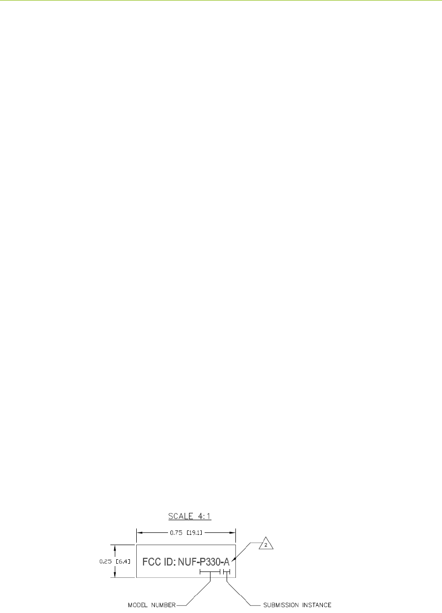
48 P330 Data Sheet / User Guide
DRAFT
8 Regulatory Compliance
The P330 with the Broadspec antenna has been designed to be in compliance with both the U.S. FCC
Part 15 subpart F regulations, sections 15.519 and 15.521 and with the European Union ETSI EN 302
065 standards.
Integration of the P330 into other user equipment will require certification of the resultant system.
While that certification is the responsibility of the end user, Time Domain will be happy to assist in
this process.
The P330 is currently undergoing testing for compliance with FCC regulations and Time Domain
expects to receive a formal FCC Grant of Equipment Authorization in early Spring 2017. Until then,
the user is free to use the equipment for evaluation and demonstration. After that authorization, the
equipment will be available for distribution and use in end products.
8.1 Compliance with the U.S. FCC Regulations
The standard P330 has been designed to be in compliance with the FCC regulations governing UWB
hand-held systems (Part 15.519) also known as “battery powered devices” or “mobile devices.” This
means that the device can be incorporated in a wide variety of products including mobile tracking
systems, mobile locators, radar-based locators, guidance and position systems, and communication
devices. Note that there are other applications which are specifically forbidden, such as use of the
devices in toys. See FCC Parts 15.519 and 15.521 for more details.
More specifically:
This device complies with 47 CFR Part 15 of the FCC Rules. Operation is subject to the
following two conditions: (1) This device may not cause harmful interference, and (2) this
device must accept any interference received, including interference that may cause
undesired operation.
Furthermore:
The user is cautioned that changes or modifications not expressly approved by the party
responsible for compliance could void the user’s authority to operate the equipment.
The label which provides the certification number is shown below in Figure 8-1.
Figure 8-1: FCC ID number
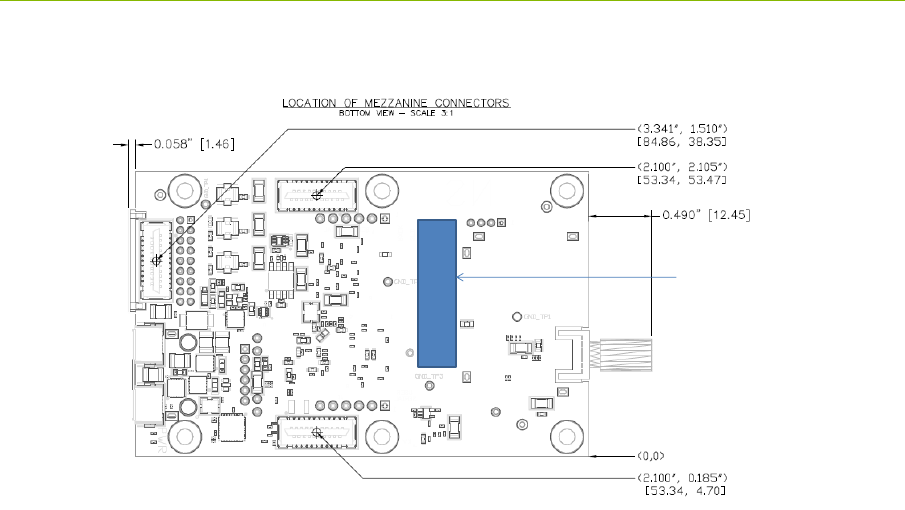
P330 Data Sheet / User Guide 49
DRAFT
This label will be located on the back or bottom side of the P330. See Figure 8-2.
Fig. 8-2: Planned location for certification number
If the P330 is incorporated into a different enclosure it is possible that the enclosure can alter the
unintentional and intentional emissions respectively.
The P330 is capable of transmitting at power levels in excess of the FCC limits for enhanced
performance. In order to use these higher powers in final applications, please consult and seek
authorization from the appropriate regulatory agencies. Time Domain has expertise in working with
regulatory agencies and can help as needed. However, the responsibility for obtaining such
authorization rests with the end user.
Additionally, the FCC regulations do not apply for US government or military applications. Proper
governmental use is described in “Government Regulations for Non-Licensed UWB Systems - Annex
K.” Developers interested in building a device for a particular government agency should discuss
their application and Annex K with that agency’s spectrum manager.
Time Domain is available to assist you with the certification process.
8.2 Compliance with the EU ETSI Standards
The standard P330 has been designed to be in compliance with the emissions mask defined in the
ETSI EN 302 065 standard.
The user is free to buy the equipment for evaluation and demonstration purposes. But before the
device can be generally marketed as an end product, its operation must be compliant with the ETSI
standard. The ETSI standard places additional requirements on operation of UWB devices beyond
just the emission mask. These requirements are related to the specific end application. For example,
depending on the user’s intended application, there can be additional limitations (or flexibilities) on
the location of fixed and mobile transmitters as well as on the rate at which transmissions can be
FCC ID
FCC Label Position

50 P330 Data Sheet / User Guide
DRAFT
generated. There are also alternate mitigation strategies which can be used to accomplish the intent of
the standard. These strategies need to be considered in the context of the target application.
The ETSI regulations also evolve over time with changes being introduced periodically. Product
developers need to keep this in mind as they evaluate applications and target products.
Finally, the P330 by itself cannot be certified. The P330 must be certified by the relevant body in the
context of the final product in which it is to be used.
Time Domain is available to assist you with the certification process.

P330 Data Sheet / User Guide 51
DRAFT
9 Import/Export Considerations
Time Domain has self-certified the P330 in all its variations under Export Commodity Control
Number (ECCN) 5A001b.4 pending formal classification from the U.S. Department of Commerce’s
Bureau of Industry and Security. This self-certification is based upon the Bureau’s previous
assignment of ECCN 5A001b.4 to the company’s P400 modules.
Products falling under ECCN 5A001b.4 are controlled for export purposes pursuant to the Commerce
Control List for National Security and Antiterrorism. For the latest information from the Commerce
Department on Export, please go to: http://www.bis.doc.gov/licensing/exportingbasics.htm.
While Time Domain has shipped products to more than twenty countries (and takes pride in doing so)
there are a small number of countries for which export license approval may be required.
Furthermore, these rules change with time. Therefore, the company reluctantly reserves the right to
refrain from selling P330s if there is a significant export concern.

52 P330 Data Sheet / User Guide
DRAFT
10 Configuration and Ordering Information
The P330 is available either as a single board (OEM Module) or as part of a Ranging and
Localization Development Kit. When ordered as part of a Kit, the P330 module is provided with a
number of hardware and software accessories.
The hardware accessories include the following:
Enclosure for P330 module: Housing made of damage-resistant plastic with clear
polycarbonate cover. Provides protection from improper handling during evaluation, testing,
and development activities.
Broadspec antenna: Time Domain’s standard UWB antenna as described in Section 7.
USB wall charger, battery, and cables: The USB battery can drive the P330 directly for
approximately 10.0 hours. The USB wall charger can drive the P330 directly from an AC
power source or can be used to recharge the battery. A short USB cable is provided for
connecting the battery to the P330 USB power port and a longer cable is provided for driving
the P330 either through the USB power port or for communicating to the P330 through the
USB communications. Most (but not all) commercially available USB battery packs will
drive the unit, so the user has the freedom to experiment with alternate battery approaches.
The P330 software offerings include the following:
RangeNet / RangeNet Lite: RangeNet is Time Domain’s GUI for demonstrating two
different ranging and localization capabilities. First, it allows the user to measure the
distance between two P330 units using TW-TOF ranging. Second, it allows the user to define
a network of P330s. More importantly, this network has been optimized for use with TW-
TOF ranging. RangeNet supports both the ALOHA and TDMA network protocols. It can
also be configured to transfer data. RangeNet “Lite” is a node-locked version of RangeNet in
that it is limited to operation with a maximum of 10 nodes. RangeNet Lite is provided to
allow the user to easily experiment with units both as standalone pairs and as members of a
network. Users interested in unrestricted operation of RangeNet should contact the factory
for information on purchase and licensing options.
All of the software packages come with sample C code and sample MATLAB code to illustrate the
API interface from a Host computer to the P330.
Table 10-1 provides the name of the part or kit, a part number, and short description of the part or
kit.
KIT Series
Part number
Description
P330 Ranging and
Localization Development
Kit
430RL01
Contains
5 P330 modules (130RM01)
5 Broadspec antennas (100ANR4)
5 enclosures (330EN01)
5 rechargeable USB batteries (340RB01)
5 USB wall chargers

P330 Data Sheet / User Guide 53
DRAFT
5 long USB cables (6 ft./1.8 m)
5 short USB cables (6 in./15cm)
RangeNet Lite (ranging and network
software, node-locked to 10 nodes)
5 hours of technical support
OEM Module Series
P330 UWB Module
130RM01
Single P330 Module (board only, no accessories).
Integratable printed circuit assembly designed to
provide precision ranging and wireless
communications with multiband (4 and 6.5 GHz)
operation. Supports Ethernet, USB, SPI, Serial, or
CAN interface.
Antenna Series
Broadspec Antenna (Male
SMA Connector)
100ANR2
UWB Antenna (3-7 GHz) with male SMA connector.
Omnidirectional antenna for use with P300 and P400
series platforms.
Broadspec Antenna (Male
SMA Connector) with Right
Angle Adapter
100ANR4
UWB Antenna (3-7 GHz) male SMA connector and
right angle SMA connector. Omnidirectional
antenna for use with P300 and P400 series platforms.
Accessory Series
P330 Enclosure
330EN01
Single P330 Enclosure. Made of damage resistant
ABS plastic with clear polycarbonate cover. Suitable
for lab use and light field testing.
Rechargeable Battery
340RB01
Rechargeable 300mAh USB battery. Provides 10
hours of continuous operation for P330.
Technical Services
Technical Support Block (10
hours)
910TS01
Ten hours of Time Domain remote engineering
technical support (phone or e-mail) for integration
and testing. Valid for one year from date of
purchase.
Technical Support Block (25
hours)
925TS01
Twenty five hours of Time Domain remote
engineering technical support (phone or e-mail) for
integration and testing. Valid for one year from date
of purchase.
Table 10-1: P330 Ordering Information
For pricing and ordering information, please contact sales@timedomain.com