Humax SV4 Satellite Radio Receiver User Manual SV4 Installation User Guide 062907a indd
Humax Co., Ltd. Satellite Radio Receiver SV4 Installation User Guide 062907a indd
Humax >
Users manual

Stratus 4
Stratus 4
Satellite Radio
User Guide
User Guide

Congratulations on the Purchase of your new SIRIUS Stratus 4
Plug-n-Play Radio
Your new SIRIUS Stratus 4 Plug-n-Play Radio lets you enjoy SIRIUS® Satellite Radio’s digital
entertainment in any vehicle where you’ve installed the included Vehicle Docking Station. Your
Stratus 4 is also compatible with the SUPH1 SIRIUS Universal Plug and Play Home Kit, the
SUPV1 SIRIUS Universal Plug and Play Vehicle Kit, and the SUBX1 SIRIUS Plug and Play
Universal Boombox (each sold separately).
Use this manual to familiarize yourself with all of your Stratus 4’s features and capabilities. For
the latest information about this and other SIRIUS products and accessories, visit http://www.
sirius.com.
[ Table of Contents ]
4
Table of Contents
TABLE OF CONTENTS . . . . . . . . . . . . . . . . . . . . . . . . . . . . . . 4
WARNING AND SAFETY INFORMATION . . . . . . . . . . . . . . . . . . . . . . 6
FCC Information . . . . . . . . . . . . . . . . . . . . . . . . . . . . . . . . 6
Canadian Compliance . . . . . . . . . . . . . . . . . . . . . . . . . . . . . . 7
General Precautions . . . . . . . . . . . . . . . . . . . . . . . . . . . . . . . 7
Warnings . . . . . . . . . . . . . . . . . . . . . . . . . . . . . . . . . . . 8
COPYRIGHTS & TRADEMARKS . . . . . . . . . . . . . . . . . . . . . . . . 10
PACKAGE CONTENTS . . . . . . . . . . . . . . . . . . . . . . . . . . . . . 11
INSTALLATION . . . . . . . . . . . . . . . . . . . . . . . . . . . . . . . . 13
Location . . . . . . . . . . . . . . . . . . . . . . . . . . . . . . . . . . . 13
Mounting the Vehicle Dock . . . . . . . . . . . . . . . . . . . . . . . . . . . 15
Installing the Antenna . . . . . . . . . . . . . . . . . . . . . . . . . . . . . 19
Connecting the Cigarette Lighter Adapter . . . . . . . . . . . . . . . . . . . . . 32
Docking Your SIRIUS Radio . . . . . . . . . . . . . . . . . . . . . . . . . . . 32
Connecting Your Stratus 4 to Your Vehicle’s Audio System . . . . . . . . . . . . . . 33
Direct Wired Audio Connection . . . . . . . . . . . . . . . . . . . . . . . . 33
Direct FM Audio Connection . . . . . . . . . . . . . . . . . . . . . . . . . 34
Cassette Adapter . . . . . . . . . . . . . . . . . . . . . . . . . . . . . . 35
Wireless Audio Connection . . . . . . . . . . . . . . . . . . . . . . . . . . 36
Wireless Audio Connection Using the FM Extender Antenna . . . . . . . . . . . . 37
Subscribing to the SIRIUS Service . . . . . . . . . . . . . . . . . . . . . . . . 48
CONTROLS . . . . . . . . . . . . . . . . . . . . . . . . . . . . . . . . . 49
SIRIUS Stratus 4 Front Panel . . . . . . . . . . . . . . . . . . . . . . . . . . 49
Vehicle Dock Reference Guide . . . . . . . . . . . . . . . . . . . . . . . . . . 50
OPERATION . . . . . . . . . . . . . . . . . . . . . . . . . . . . . . . . . 51
Display Screen Information . . . . . . . . . . . . . . . . . . . . . . . . . . . 51
Changing Channels and Categories . . . . . . . . . . . . . . . . . . . . . . . . 52
Selecting Channels Directly . . . . . . . . . . . . . . . . . . . . . . . . . . . 52
Channel Presets . . . . . . . . . . . . . . . . . . . . . . . . . . . . . . . 53
FM Transmitter Presets . . . . . . . . . . . . . . . . . . . . . . . . . . . . . 54
Jump Button . . . . . . . . . . . . . . . . . . . . . . . . . . . . . . . . . 55
[ Table of Contents ] 5
MENU OPTIONS . . . . . . . . . . . . . . . . . . . . . . . . . . . . . . . 56
SIRIUS ID . . . . . . . . . . . . . . . . . . . . . . . . . . . . . . . . . . 56
FM Transmitter . . . . . . . . . . . . . . . . . . . . . . . . . . . . . . . . 57
Settings . . . . . . . . . . . . . . . . . . . . . . . . . . . . . . . . . . . 59
Display Options . . . . . . . . . . . . . . . . . . . . . . . . . . . . . . 59
Audio Level . . . . . . . . . . . . . . . . . . . . . . . . . . . . . . . . 60
Tones . . . . . . . . . . . . . . . . . . . . . . . . . . . . . . . . . . 61
Clock . . . . . . . . . . . . . . . . . . . . . . . . . . . . . . . . . . . 61
Jump Settings . . . . . . . . . . . . . . . . . . . . . . . . . . . . . . . 62
Channel Lock . . . . . . . . . . . . . . . . . . . . . . . . . . . . . . . 63
Signal . . . . . . . . . . . . . . . . . . . . . . . . . . . . . . . . . . . . 65
Factory Default . . . . . . . . . . . . . . . . . . . . . . . . . . . . . . . . 65
TROUBLESHOOTING . . . . . . . . . . . . . . . . . . . . . . . . . . . . . 67
OPTIONAL ACCESSORIES . . . . . . . . . . . . . . . . . . . . . . . . . . . 68
SPECIFICATIONS . . . . . . . . . . . . . . . . . . . . . . . . . . . . . . . 70
WARRANTY . . . . . . . . . . . . . . . . . . . . . . . . . . . . . . . . . 71
SIRIUS ID . . . . . . . . . . . . . . . . . . . . . . . . . . . . . . . . . . 72

[ Warning and Safety Information ]
6
Warning and Safety Information
FCC Information
This device complies with part 15 of the FCC Rules. Operation is subject to the following two
conditions:
This device may not cause harmful interference, and
This device must accept any interference received, including interference that may cause
undesired operation.
Note: This equipment has been tested and found to comply with the limits for a
CLASS B digital device, pursuant to Part 15 of the FCC Rules. These limits are
designed to provide reasonable protection against harmful interference when the
equipment is operated in a commercial environment. This equipment generates,
uses, and can radiate radio frequency energy and, if not installed and used in
accordance with the instructions, may cause harmful interference to radio com-
munications. However, there is no guarantee that interference will not occur in a
particular installation. If this equipment does cause harmful interference to radio
or television reception, which can be determined by turning the equipment off
and on, the user is encouraged to try to correct the interference by one or more
of the following measures:
Reorient or relocate the receiving antenna.
Increase the separation between the equipment and the receiver.
Connect the equipment into an outlet on a circuit different from that to
which the receiver is connected.
Consult the dealer or an experienced radio/TV technician for help.
1.
2.
3.
4.
WARNING
Changes or modifications not expressly approved by the manufacturer could void the user’s
authority to operate the equipment.
1.
2.
[ Warning and Safety Information ] 7
Canadian Compliance
This Class B digital apparatus complies with Canadian ICES-003.
Cet appareil numérique de la classe B est conforme à la norme NMB-003 du Canada.
General Precautions
Liquid Crystal Precautions
If the LCD screen on the radio is damaged, do not to touch the liquid crystal fluid. If any of the
following situations happen, take the action indicated:
If the liquid crystal fluid comes in contact with your skin, wipe the skin area with a cloth
and then wash the skin thoroughly with soap and running water.
If the liquid crystal fluid gets into your eye, flush the eye with clean water for at least 15
minutes. Seek medical care.
If the liquid crystal fluid is ingested, flush your mouth thoroughly with water. Drink large
quantities of water and induce vomiting. Seek medical care.
Safety Precautions
Be sure to observe the following warnings. Failure to follow these safety instructions and
warnings may result in a serious accident.
Do not operate your Stratus 4 in a way that might divert your attention from driving safely.
As a driver, you alone are responsible for safely operating your vehicle in accordance with
traffic safety laws at all times.
Do not install the unit where it may obstruct your view through the windshield, or of your
vehicle’s indicator displays.
Do not install the unit where it may hinder the function of safety devices such as an airbag.
Doing so may prevent the airbag from functioning properly in the event of an accident.
Be sure the unit is installed as described in the installation instructions which accompa-
ny each accessory kit. SIRIUS Satellite Radio is not responsible for issues arising from
installations which were not installed according to the instructions.
1.
2.
3.
•
•
•
•
[ Warning and Safety Information ]
8
To avoid short circuits, do not open the unit, and never put or leave any metallic objects
(coins, tools, etc.) inside the unit.
If the unit emits smoke or unusual odors, turn the power off immediately, and disconnect the
unit from any power source.
Do not drop the unit or subject it to strong shocks.
If the unit doesn’t seem to be working properly, turn the unit off, wait 10 seconds and then
turn it on again.
The installation and use suggestions contained in this manual are subject to any restrictions
or limitations that may be imposed by applicable law. The purchaser should check
applicable law for any restrictions or limitations before installing and/or operating this unit.
Do not install the FM Extender Antenna where it will hinder or block your view. In some states
it may be illegal to mount it on the windshield of your vehicle. Check applicable law for any
restrictions or limitations before installing the FM Extender Antenna on your windshield.
Do not install the FM Extender Antenna where it may hinder the function of safety devices
such as an airbag. Doing so may prevent the airbag from functioning properly in the event
of an accident.
Warnings
Notice To Drivers In California and Minnesota
State law prohibits drivers in California and Minnesota from using suction mounts on their wind-
shields while operating motor vehicles. Other dashboard or friction mounting options should be
used. SIRIUS does not take any responsibility for any fines, penalties, or damages that may be
incurred as a result of disregarding this notice. (See California Vehicle Code Section 26708(a);
Minnesota Statutes 2005, Section 169.71)
Operating Temperature
The Stratus 4 is designed to operate between -20° to +85° C (-4° to +185° F). Avoid leaving
the radio in a vehicle or elsewhere where the temperature may fall outside this range. Extreme
temperatures or extreme temperature fluctuations can degrade the performance of the LCD
display screen, and possibly damage it.
•
•
•
•
•
•
•
[ Warning and Safety Information ] 9
Cleaning and Maintenance
If the radio or accessories become dirty, turn the power off and wipe it clean with a soft cloth.
Do not use hard cloths, strong cleaning fluids, paint thinner, alcohol, or other volatile solvents
to clean. These may cause damage to the radio.
Cigarette Lighter Adapter
The Vehicle Dock cannot be powered directly from a vehicle’s 12VDC power system. It must be
powered from the vehicle’s cigarette lighter or similar power port using the included Cigarette
Lighter Adapter or an equivalent DC power adapter (see your local electronics dealer).
Connecting the Vehicle Dock directly to the vehicle’s 12VDC power system may result in
damage to the Vehicle Dock or SIRIUS radio, or both.

[ Copyrights & Trademarks ]
10
Copyrights & Trademarks
© 2007 SIRIUS Satellite Radio Inc. All Rights Reserved.
® “SIRIUS”, the SIRIUS dog logo, channel names and logos are trademarks of SIRIUS Satellite
Radio Inc. “NFL” and the NFL Shield logo, and the NFL Sunday Drive name and logo are
registered trademarks of the National Football League. “NHL” and the NHL Shield are registered
trademarks of the National Hockey League. “NBA” and the NBA silhouette logo are registered
trademarks of NBA Properties Inc. All other trademarks, service marks, sports team names,
album art, and logos are the property of their respective owners. All Rights Reserved.
Portions of the software on this radio are licensed under the eCos License. Distribution of
eCos requires that the eCos source code be made available to SIRIUS Satellite Radio custom-
ers. The eCos License and eCos source code are available to the public at http://www.sirius.
com/ecoslicense.
SIRIUS Satellite Radio reserves all rights to all radio software not covered under the eCos
license. This includes all portions of radio software that were not distributed to SIRIUS as part
of the eCos operating system.
Hardware, subscription and activation fee required. For full Terms & Conditions, visit
http://sirius.com. Prices and programming are subject to change. Not available in HI and AK.
Equipment and subscription sold separately. Installation required with some equipment.
[ Package Contents ] 11
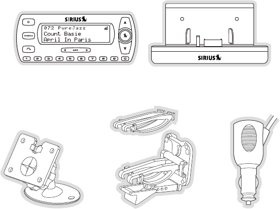
Package Contents
The following items are included with your purchase of the SIRIUS Stratus 4 radio:
Stratus 4 RadioStratus 4 Radio Vehicle DockVehicle Dock
Adhesive Dash MountAdhesive Dash Mount Vent Mount &
Extended Vent Hooks
Vent Mount &
Extended Vent Hooks
Cigarette Lighter
Adapter
Cigarette Lighter
Adapter
[ Package Contents ]
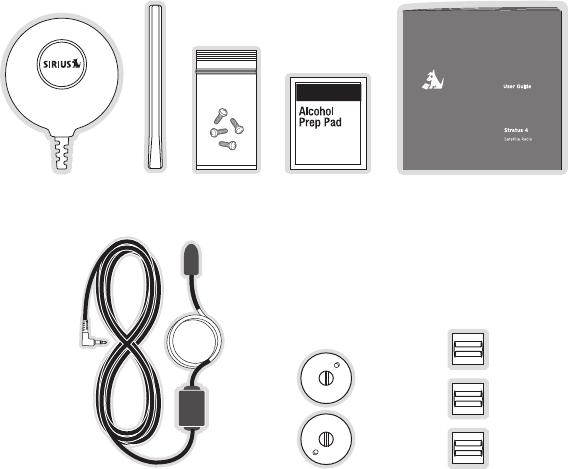
12
Unpack your SIRIUS Stratus 4 radio carefully and make sure that everything shown is
present. If anything is missing or damaged, or if your the radio fails to operate, notify your dealer
immediately. We recommend that you retain the original carton and packing materials in case
you need to ship your radio in the future.
Antenna
Cover/Tail
Antenna
Cover/Tail
Alcohol
Swab
Alcohol
Swab
ScrewsScrewsMagnetic
Antenna
Magnetic
Antenna
User GuideUser Guide
Suction Cups (2)Suction Cups (2)FM Extender AntennaFM Extender Antenna Self Adhesive
Cable Guides (3)
Self Adhesive
Cable Guides (3)
[ Installation ] 13
Installation
SIRIUS suggests that you have your Stratus 4 professionally-installed in your vehicle. Professional
installation provides an experienced technician to install this product in your vehicle, advice
for selecting a suitable mounting location for the Vehicle Dock, installation of the antenna,
and proper routing of all the necessary wires and cables. If the locations of your SIRIUS
radio and your vehicle’s FM antenna make the performance the SIRIUS radio’s built-in
FM transmitter within your vehicle poor, a professional installer will have the necessary
accessories to install an optional FM Direct Adapter or audio cable to connect the audio output
of the Vehicle Dock directly to your vehicle’s audio system. Ask your SIRIUS retailer if they
provide professional installation services, or can recommend a professional installation service.
Location
When installing the Vehicle Dock in your vehicle, choose a location in your vehicle where it will
not block your vision, interfere with the vehicle controls, or obstruct the air bag. The location
should be easily accessible and provide good visibility of the display, and should not be located
where it will be in direct sunlight which will affect the visibility of the display screen.
[ Installation ]
14
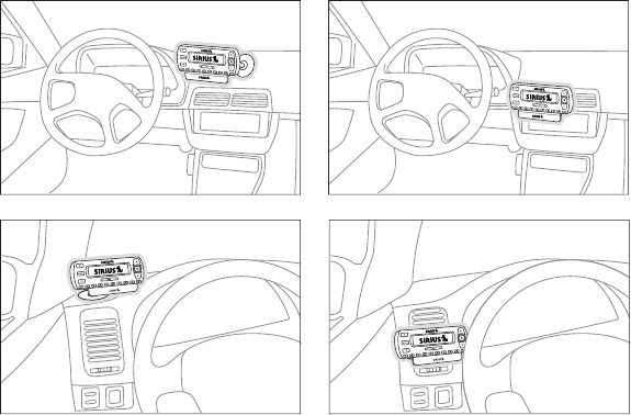
Figure 1 shows two examples of the Stratus 4 mounted in a vehicle: A is the dash mount
method, and B is the vent mount method using the vent mount clip.
A. B.
A.
B.
Figure 1
[ Installation ] 15
Mounting the Vehicle Dock
Dash Mount Method (A)
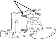
Attach the dash mount to the vehicle dock using the provided screws (see Figure 2).
Select the mounting position carefully before adhering the mount to your vehicle. Once the
mount has been adhered to a surface, it will not be possible to remove it and adhere it again.
Once you’ve selected a mounting location, clean the mounting surface area in the vehicle with
the provided alcohol swab. Peel the protective material off the adhesive on the foot and press
the foot firmly against the vehicle surface.
Allow the adhesive to adhere for a minimum of 2-4 hours before using the mount. The best
adhesion occurs after 24 hours.
Attach Dock
to Mount with
Included Screws
Figure 2
[ Installation ]
16
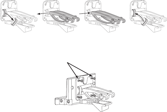
Vent Mount Method (B)
To mount the vehicle dock using the vent mount, install the vent mount as follows:
If the vent louvers in your vehicle are recessed, you may need to use the supplied longer
vent hooks with the vent mount. Refer to Figure 3 and install the longer vent hooks into the
vent mount. Be sure to observe the orientation of the vent hooks as shown.
Attach the vent mount to the vehicle dock using the provided screws (see Figure 4).
1.
2.
Attach Dock
to Mount with
Included Screws
Figure 4
Slide Short
Vent Hooks Out
Remove
End Cap
Slide Extended
Vent Hooks In
Replace
End Cap
Figure 3
[ Installation ] 17
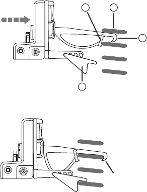
Refer to Figure 5 and attach the vent mount to a heating/air conditioning vent in your
vehicle. Position the two tension springs A against a vent louver B. Then push the
vent mount into the vent, far enough so that the hooks C drop down and hook the rear
of the vent louver (see Figure 6). Once you are sure that the hooks have grasped a
vent louver, the tension springs A will keep the vent mount hooked to the louver.
3.
FM OUT ANT
C
B
A
D
PUSH
FM OUT ANT HOOKED
Figure 5
Figure 6
[ Installation ]
18
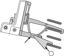
The angle of the docking station may be changed by changing the position of foot D on
the vent mount to a different adjustment hole (see Figure 7).
4.
FM OUT ANT
ADJUSTMENT
HOLES
D
Figure 7
[ Installation ] 19
Installing the Magnetic Antenna
Caution
Because adhesive is used in the installation of the Rubber Antenna Cover/Tail, we recommend
that you install the antenna at or above room temperature (68° F). The adhesive on the Rubber
Cover/Tail may not adhere properly to the vehicle roof at temperatures lower than this. Warmer
temperatures will also make it easier to route of the antenna cable through the rubber molding
around the windows and in other areas in the vehicle. Maximum adhesion usually occurs within
72 hours at room temperature, so you should avoid car washes as well as other contact with
the antenna and Rubber Cover/Tail during this 72 hour period.
Warning
Be sure not to cut, damage, or puncture the external jacket of the antenna cable during the
installation procedure. Damage to the antenna cable can degrade the SIRIUS signal or make
it unavailable, and can also cause water to intrude via the cable into the antenna causing the
antenna to fail.
Do not lengthen or shorten the antenna cable by cutting it. Doing so will cause the antenna to
not function properly.
Installation
Installing the magnetic antenna consists of two steps:
Mounting the magnetic antenna and Rubber Antenna Cover/Tail on the vehicle
Routing the antenna cable through the vehicle to the Vehicle Dock
ANTENNA MOUNTING
The SIRIUS Magnetic Mount Vehicle Antenna has a strong magnetic mount designed to hold
it in place during normal driving conditions (highway/city). This also makes the antenna easy to
remove for transferring it to other vehicles.
•
•
[ Installation ]
20
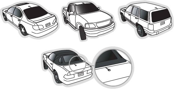
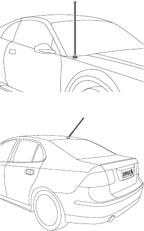
Figure 8 shows the optimal mounting location for the antenna on several types of vehicles.
These mounting positions should be observed when installing the antenna:
Sedan/Coupe/SUV/Mini-Van: Install the antenna at the rear center of the roof, near the
rear window.
Pickup Truck: Install the antenna at the front center of the roof, near the windshield.
Convertible: Install the antenna at the front center of the trunk lid, near the rear window.
The SIRIUS antenna needs to have an unobstructed area of 3 inches by 3 inches around it.
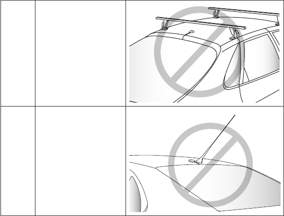
It is important to mount the antenna where no obstructions will block the antenna from receiving
the SIRIUS signal. Objects which can obstruct the antenna could be a roof rack, a sunroof, a
roof-mounted cargo container, another antenna, etc. If your vehicle has a potential obstruction,
be sure that the SIRIUS antenna is mounted at least 3 inches away from it (but no closer than
3 inches from the roof edge, or trunk lid in the case of a convertible).
Note: Read the DO and DO NOT installation tips beginning on page 29 for additional antenna
installation information.
•
•
•
Sedan/Coupe Pickup Truck SUV/Mini-Van
Convertible
Figure 8
[ Installation ] 21
Follow this procedure to mount the antenna:
Select an appropriate mounting position for your type of vehicle that has an unobstructed
area of 3 inches by 3 inches around the antenna.
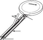
Attach the Rubber Cover/Tail to the antenna, as shown in Figure 9, and press the antenna
cable into the rubber cover/tail. The Rubber Cover/Tail will help to position the antenna
the correct distance from the edge of the roof or trunk lid.
Clean the surface area of the vehicle where you will be installing the antenna with the
alcohol prep pad.
Peel the protective material from the adhesive strips (see Figure 9) and press the rubber
Cover/Tail firmly into place on the vehicle.
Double check that the location of the antenna and rubber cover/tail are correct, and
continue to press firmly down on the Rubber Cover/Tail for another 30 seconds. At room
temperature (68° F), maximum adhesion usually occurs within 72 hours. During this
period, avoid car washes and other contact with the antenna and the Rubber Antenna
Cover/Tail.
CABLE ROUTING
After you have mounted the antenna you can route the antenna cable to the SIRIUS
Vehicle Dock. Separate antenna cable routing procedures are provided for each type of vehicle:
Sedan/Coupe, Pickup Truck, SUV/Mini-Van and Convertible.
1.
2.
3.
4.
5.
Rubber Antenna
Cover/Tail
Protective
Strips Strain
Relief
Cable
Magnetic Antenna
(Upside-Down)
Figure 9
[ Installation ]
22
Note that additional breakout illustrations for each step of the antenna cable routing procedures
can be found on the SIRIUS website at http://www.sirius.com. Click on the Install/Activate link
and then follow the link for the Car Installation Tips.
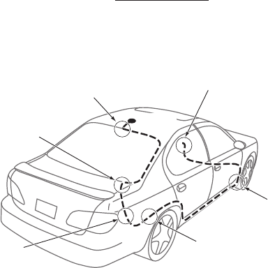
Sedan /Coupe Antenna Cable Routing Procedure
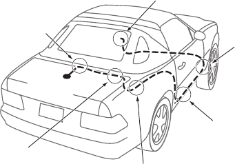
Figure 10 shows how the antenna cable should be routed from the antenna to your SIRIUS
radio in a sedan/coupe.
Follow these detailed cable installation instructions:
Feed the cable from the antenna underneath the rubber molding around the rear window.
Use a plastic putty knife or similar object to lift the rubber molding around the rear window
and tuck the antenna cable underneath the molding. Route the antenna cable around and
down the window to the lowest point. If your rear window does not have rubber molding,
SIRIUS recommends consulting with a professional installer.
1.
1. Feed Cable Under
Rubber Molding
Around Window
4. Route Cable from Trunk Under
Interior Trim, into Cabin and
Towards Front of Vehicle
6. Bring Cable Out To
SIRIUS
Receiver
Location
5. Bring Cable out from Trim
and Route Under Carpet to
Dashboard or Console.
2. Route Cable Out of
Window Molding and
Into Weatherstripping
Around Trunk Opening
3. Route Cable
Along Trunk Wall
and Into Cabin
ANTENNA
Figure 10
[ Installation ] 23
Route the antenna cable out of the window molding and into the rubber weather stripping
around the trunk opening. Lift the weather stripping from the opening and tuck the cable
inside it, then replace the weather stripping. To avoid sharp bends in the cable, run the
cable inside of the weather stripping for a few inches, then remove the cable from the
weather stripping inside of the trunk. Keep the cable away from hinges, gears, etc., that
could damage it.
Route the cable out from the rubber weather stripping and along the trunk wall. Continue
routing the cable into the cabin through a conduit or along an existing wiring harness.
Route the cable through the main cabin area under the interior trim, towards the front
of the vehicle. Use the plastic putty knife to lift the plastic trim just enough to tuck the
cable under underneath. Avoid side airbag locations on back pillars and above the doors.
(Airbag locations are marked with “SRS” logos.) Be careful not to crimp or cut the cable.
Bring the cable out from the trim near the firewall and route it under the carpet toward
the dashboard or console. Coil any excess cable in a hidden location, such as under the
carpet, keeping it away from any vehicle pedals or controls. Secure the excess cable with
wire ties.
Bring the end of the cable out at the SIRIUS Vehicle Dock location. Leave yourself enough
cable so you can easily connect it to the antenna connector on the Vehicle Dock.
2.
3.
4.
5.
6.
[ Installation ]
24
Pickup Truck Antenna Cable Routing Procedure
Figure 11 shows how the antenna cable should be routed from the antenna to your SIRIUS
radio in a pickup truck.
Follow these detailed cable installation instructions:
Use a plastic putty knife or similar tool to lift the rubber molding around the windshield and
tuck the antenna cable underneath it.
Continue tucking the cable underneath the windshield molding around the windshield to
the lowest corner.
At the lowest corner of the windshield, route the cable out of the windshield molding and
into the rubber weather stripping around the door opening. Lift the weather stripping from
the opening and tuck the cable inside it, then replace the weather stripping. Run the cable
inside of the weather stripping to the bottom of the door opening.
Pull the cable out of the weather stripping at the bottom of the door opening and route
it under the carpet toward the dashboard. Coil any excess cable in a hidden location,
such as under the carpet, keeping it away from any vehicle pedals or controls. Secure the
excess cable with wire ties.
1.
2.
3.
4.
1. Route Cable Under
Rubber Molding
Around Windshield
2. Continue Tucking Cable
Under Molding To
Bottom of Windshield
3. Route Cable Out of Molding
and Into Weatherstripping
Around Door Opening.
Continue to Bottom of
Door Opening.
4. Bring Cable out from
Weatherstripping and
Route Under Carpet
5. Bring Cable Out to
SIRIUS Receiver
Location
ANTENNA
Figure 11
[ Installation ] 25
Bring the end of the cable out at the SIRIUS Vehicle Dock location. Leave yourself enough
cable so you can easily connect it to the antenna connector on the Vehicle Dock.
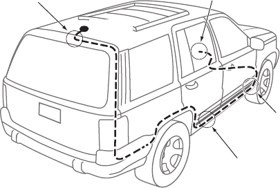
SUV/ Mini-Van Antenna Cable Routing Procedure
Figure 12 shows how the antenna cable should be routed from the antenna to your SIRIUS
radio in an SUV or a Mini-Van.
Follow these detailed cable installation instructions:
Feed the antenna cable underneath the rubber weather stripping of the rear tailgate win-
dow/door and route the cable along the rear hatch. Lift the weather stripping from the
opening and tuck the cable inside it, then replace the weather stripping. Pull the cable out
from weather stripping and route it into the cabin under the interior trim. Avoid hinges or
gears that could crimp or cut the cable.
5.
1.
1. Feed Cable Under
Rubber Seal Around
Hatch Opening
3. Route Cable
Under Carpet
to Dashboard
4. Bring Cable Out To
SIRIUS
Receiver
Location
2. Route Cable Under Interior
Trim, into Cabin and
Towards Front of Vehicle
ANTENNA
Figure 12
[ Installation ]
26
Route the cable through the SUV’s main cabin area under the interior trim, towards the
front of the vehicle. Use a plastic putty knife to lift the plastic trim just enough to tuck the
cable under underneath. Avoid side airbag locations on back pillars and above the doors.
(Airbag locations are marked with “SRS” logos.) Be careful not to crimp or cut the cable.
Bring the cable out from the trim near the firewall and route it under the carpet toward
the dashboard or console. Coil any excess cable in a hidden location, such as under the
carpet, keeping it away from any vehicle pedals or controls. Secure the excess cable with
wire ties.
Bring the end of the cable out at the SIRIUS Vehicle Dock location. Leave yourself enough
cable so you can easily connect it to the antenna connector on the Vehicle Dock.
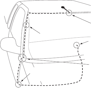
Convertible Antenna Cable Routing Procedure
Figure 13 shows how the antenna cable should be routed from the antenna to your SIRIUS
radio in a convertible.
2.
3.
4.
6. Bring Cable Out To
SIRIUS
Receiver
Location
1. Bring Cable from
Antenna Into Inside
of Trunk Lid
2. Tape Cable Along
Inside of Lid to
Hinge Strut
4. Route Cable from Trunk
Under Interior Trim, into
Cabin and Towards Front
of Vehicle
5. Bring Cable out from
Trim and Route Under
Carpet to Dashboard
or Console.
3. Tie Cable to Hinge Strut, Allowing
Slack for Lid to Open and Close.
Route Cable Into Cabin
Through Existing Wire
Channel.
ANTENNA
Figure 13
[ Installation ] 27
Follow these detailed cable installation instructions:
Bring the cable from the antenna into the trunk at the front edge of the trunk lid. Keep
any bends in the cable loose. Tape or tie the cable along the inside of the trunk lid to the
trunk lid hinge strut.
Allow enough slack in the cable so the trunk lid can easily open and close and keep the
cable away from hinges, gears, etc., that could crimp or cut it. Route the cable along the
trunk wall and into the cabin through a conduit or along an existing wiring harness.
Route the cable through the main cabin area under the interior trim, towards the front of
the vehicle. Use a plastic putty knife to lift the plastic trim just enough to tuck the cable un-
der underneath. Avoid side airbag locations on back pillars and above the doors. (Airbag
locations are marked with “SRS” logos.) Be careful not to crimp or cut the cable.
Bring the cable out from the trim near the firewall and route it under the carpet toward
the dashboard or console. Coil any excess cable in a hidden location, such as under the
carpet, keeping it away from any vehicle pedals or controls. Secure the excess cable with
wire ties.
Bring the end of the cable out at the SIRIUS Vehicle Dock location. Leave yourself enough
cable so you can easily connect it to the antenna connector on the Vehicle Dock.
TIPS
The following DO and DO NOT antenna mounting tips illustrate how to install the antenna for
optimal performance, and also illustrate where the antenna should not be installed.
DO
Mount the antenna on the
roof, at least 3 inches from
the edge.
1.
2.
3.
4.
5.
[ Installation ]
28
DO
Mount the antenna on
the roof where it has a
clear view of the sky in all
directions.
DO
Mount the antenna on the
roof where it has at least
3 inches of clear space
around it.
3”
[ Installation ] 29
DO
Use the supplied Rubber
Tail Cover to protect the
antenna cable.
DO
NOT
Don’t mount the antenna
inside the vehicle, for
example, on the dashboard.
DO
NOT
Don’t mount the antenna on
any of the vehicle’s front,
back or side pillars.
[ Installation ]
30
DO
NOT
Don’t mount the antenna
close to a roof rack. Adjust
the rack so it’s further away
from the antenna or move
the antenna closer to the
center of the roof.
DO
NOT
Don’t mount the antenna
close to another antenna.
Mount it at least 3 inches
away.
[ Installation ] 31
DO
NOT
Don’t mount the antenna
closer than 3 inches from
the edge of the roof. Use
the supplied rubber tail/
cover as a guide for judging
proper length and correct
positioning.
After you’ve routed the cable to the SIRIUS Vehicle Dock, connect the antenna cable to the ANT
connection on the right side of the Vehicle Dock. (See Figure 14.)
FM OUT ANT
Vehicle Dock
(Right Side)
Antenna
Connection
Figure 14
[ Installation ]
32
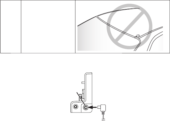
Connecting the Cigarette Lighter Adapter
Connect the provided cigarette lighter adapter to the 5VDC connector on the back of the Ve-
hicle Dock. (See Figure 15.)
Note: Do not power the Vehicle Dock directly from your vehicle’s 12VDC power system
without using the Cigarette Lighter Adapter. This could damage the Vehicle Dock, your
SIRIUS receiver or both.
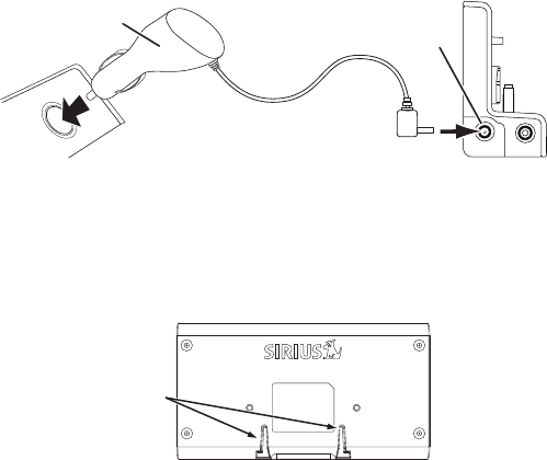
Docking Your SIRIUS Radio
To place your SIRIUS radio into the Vehicle Dock, align the radio against the rear of the Dock
so that the rails on the Dock fit into the mounting slots in the back of the radio (Figure 16).
Slide the radio all the way down onto the Dock so that it fits firmly.
AUDIO
5VDC
Vehicle
Dock
(Left Side)
5V DC
Connection
12V
Power
Outlet
Cigarette Lighter
Adapter
Figure 15
Mounting
Slots
Figure 16
[ Installation ] 33
Connecting Your SIRIUS Stratus 4 to Your Vehicle’s Audio
System
There are two ways to connect your SIRIUS Stratus 4 to your vehicle’s audio system:
Direct Connection or Wireless Connection. Which one will perform best in your vehicle
depends on your vehicle’s audio system.
For the latest information go to http://www.sirius.com/vehicleinstallation.
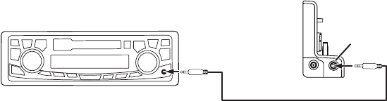
Direct Wired Audio Connection
If your vehicle’s audio system has an “AUX IN” or “LINE IN” jack it is the best-quality audio
connection you can use for your SIRIUS radio. (And if the AUX IN or LINE IN connector is located
somewhere on the front of your vehicle radio or elsewhere in the cabin, this is also the easiest
way to connect your SIRIUS receiver.)
1. Purchase an audio cable that matches the connection type of your vehicle’s audio system and
your SIRIUS Vehicle Dock at your local electronics retailer.
• The Vehicle Dock requires a male 1
/
8” stereo connector.
2. Plug the cable’s male 1
/
8” stereo connector into the AUDIO jack on the left side of the Vehicle
Dock. Plug the other end into the AUX IN/LINE IN connector on your vehicle’s audio system.
(See Figure 17.)
AUDIO
5VDC
Aux In Mode
Stereo Cable (Sold Separately)
AUDIO
Jack
Vehicle Radio
To AUX IN
or LINE IN
Connector
Vehicle Dock
(Left Side)
Figure 17
[ Installation ]
34
Direct FM Audio Connection
If your vehicle’s audio system does not have an AUX IN/LINE IN connection, a SIRIUS FM Direct
Adapter (sold separately) will provide the next best quality connection between your SIRIUS Stra-
tus 4 and your vehicle radio. You will listen to your SIRIUS Stratus 4 through your car radio’s FM
tuner, but the SIRIUS FM Direct Adapter connects your vehicle’s FM radio directly to your SIRIUS
radio’s FM OUT jack, eliminating the outside static and interference you sometimes experience when
using a wireless FM connection. (See Figure 18.)
NOTE: Professional installation may be required. See your local SIRIUS retailer. The SIRIUS
FM Direct Adapter is available at your local SIRIUS retailer or at http://shop.sirius.com.
Follow to the instructions included with the FM Direct Adapter.
FM OUT ANT
Vehicle Radio
Antenna
Connection
Vehicle
Antenna
FM OUT
Jack
Vehicle Dock
(Right Side)
FM Direct Adapter
(Sold Separately)
FM Mode
Figure 18
[ Installation ] 35
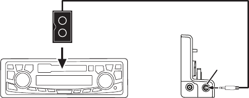
Cassette Adapter
If your vehicle’s audio system has a cassette player you can purchase a cassette adapter
from your local electronics retailer or from SIRIUS at http://shop.sirius.com. Plug the adapter’s
connector into the AUDIO jack on the left side of the Vehicle Dock, and insert the adapter into
your vehicle’s cassette player. (See Figure 19.)
Note: Refer to the cassette adapter’s instructions for correct use.
AUDIO
5VDC
Cassette Mode
Vehicle Radio
Cassette Adapter (Sold Separately)
Vehicle Dock
(Left Side)
AUDIO
Jack
Figure 19
[ Installation ]
36
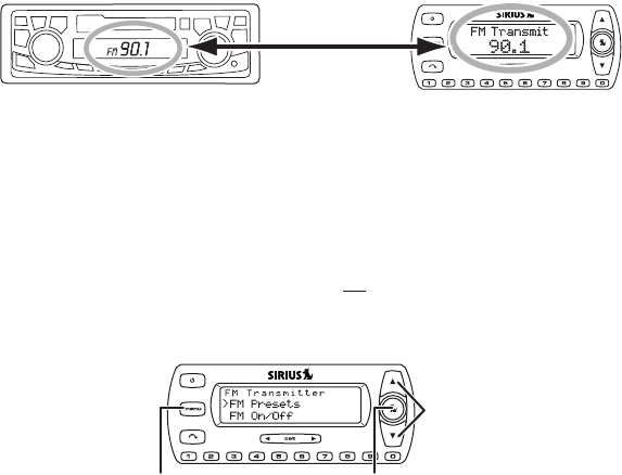
Wireless Audio Connection
If you cannot connect your SIRIUS Stratus 4 directly to your vehicle’s audio system, your SIRIUS
Stratus 4 contains an FM transmitter that will ‘broadcast’ its audio to your vehicle’s FM radio.
To use this you need to tune the Stratus 4’s FM transmitter to an FM frequency that’s not be-
ing used in your area (See Figure 20). If you use an FM channel that is being used by a local
broadcaster, it will interfere with the performance of your SIRIUS radio.
1. Tune through your vehicle radio’s FM channels to find an FM channel (between 88.1MHz
and 107.9MHz) that is not broadcasting in your area.
• If you’re not sure which FM channels are not broadcasting in your home or travel cities,
you can also go to http://www.sirius.com/fmchannel and search for a suggested FM
channel based on your zip code.
2. Once you have located an FM channel that is not broadcasting in your area, save it as a
preset on your vehicle radio. This will become your SIRIUS preset.
3. Dock your SIRIUS receiver and turn its power ON. Wait for the Channel Update to finish
before pressing any buttons.
4. Press and hold the MENU button. The Stratus 4’s display will show the FM TRANSMITTER
display (see Figure 21).
SIRIUS SV4Vehicle Radio
MATCH
FREQUENCIES
Figure 20
Select
Button
Channel
UP/DOWN
Buttons
MENU
Button
Figure 21
[ Installation ] 37
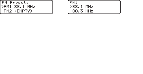
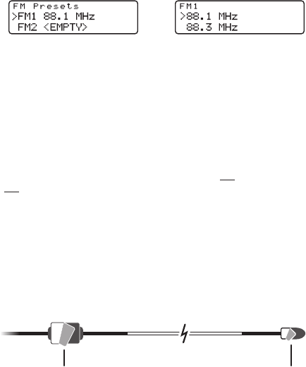
5. Use the Channel UP/DOWN buttons to highlight FM PRESETS and press the Select
button. The FM PRESETS screen will appear (see Figure 22, left).
6. Select FM1. The FM1 preset screen will appear (see Figure 22, right).
Note: FM1 is factory-set to 88.1MHz (indicated by a check-mark). This may not be the
best frequency for your area.
7. Use the Channel UP/DOWN buttons to highlight the same FM frequency that you set
your vehicle’s radio to in Step 2. A check-mark will appear next to the frequency.
8. Press the Select button to set the FM Transmitter frequency and return to the FM PRESETS
screen.
9. Press the MENU button twice to return to the Default screen.
To listen to your SIRIUS radio, turn your SIRIUS radio ON, then turn your vehicle’s FM radio ON
and press the SIRIUS preset you set in Step 2, on page 36.
TIP: If you regularly travel between cities with different active FM channels, you may need to
find channels that are not broadcasting in each city. Your SIRIUS Stratus 4 can store 5 different
preset FM transmitter channels so you can easily switch to the best FM channel for each city.
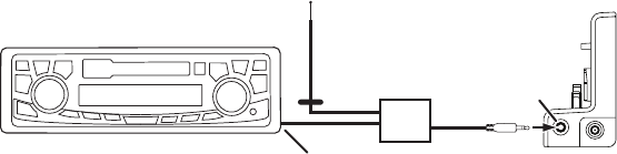
Wireless Audio Connection Using the FM Extender Antenna
Your SIRIUS Stratus 4 radio includes an FM Extender Antenna that can maximize your Stratus
4’s audio quality when using a wireless audio connection. Should the wireless audio quality with-
out the FM Extender Antenna be not acceptable, you can try using the FM Extender Antenna (or
opt for a direct connection, as described previously). Proper placement of the FM Extender An-
tenna inside your vehicle in close proximity to the vehicle’s own FM antenna will provide a strong
FM signal for good reception.
Because of the different kinds and locations of radio antennas found in different vehicles,
SIRIUS suggests that you have the FM Extender Antenna professionally-installed in your vehicle.
Professional installation provides an experienced technician to install the Extender Antenna,
knowledge of your vehicle for locating its radio antenna, and routing the cable and connecting it to
Figure 22
[ Installation ]
38
your SIRIUS radio. Ask your SIRIUS retailer if they provide professional installation services, or can
recommend a professional installation service.
The FM antennas found in vehicles are of four distinct types:
Aerial-Type Fender-Mounted
Radio Antenna:
A fixed or retractable aerial antenna
located on the front or rear fender of
the vehicle.
•
Aerial-Type Roof-Mounted
Radio Antenna:
A fixed aerial antenna mounted on the
roof (often at the front or rear of the
roof, just above the window glass).
•
[ Installation ] 39
Before attempting installation, you should verify the type and location of the FM antenna in your
particular vehicle. If you have trouble locating it, consult the manual which accompanied your
vehicle, consult a dealer for your type of vehicle, or consult a professional installer.
On-Glass Type Radio Antenna:
Wires on the window glass of the
vehicle, usually near the top of the
window. It may be located on the
windshield glass, the rear window
glass, or a rear side window in some
SUV and mini-van type vehicles (and
other vehicles). It will look similar
to the rear window defroster wires
found in many vehicles.
•
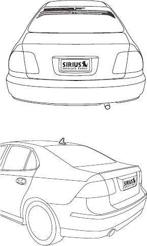
“Shark-Fin” Type Radio Antenna:
A device resembling a shark fin (or
other shape) located on the vehicle
roof above the rear window.
•
[ Installation ]
40
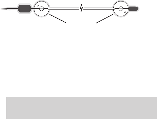
The FM Extender Antenna should be mounted inside the vehicle, as close as possible to the
vehicle antenna. A test mounting should be done first using the included suction cup mounts
to test the installation. Once you find a location that provides good results, you will remove the
suction cups and permanently adhere the FM Extender Antenna using the supplied adhesive
mounts.
To install the FM Extender Antenna in your vehicle, follow these instructions:
1. Attach the suction cups to the FM Extender Antenna in the positions shown in Figure 22.
2. In this step, follow the specific instructions in sub-step a, b, c, or d depending on the type
of radio antenna in your vehicle:
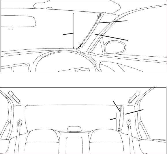
a. Installation Instructions for Vehicles with Aerial-Type Fender-Mounted Antenna.
For vehicles where the radio antenna is located on the front fender, the FM Extender
Antenna should be mounted vertically on the front windshield at the edge of the
glass nearest to the antenna (see Figure 23).
For vehicles where the radio antenna is located on the rear fender, the FM
Extender Antenna should be mounted vertically on the rear window at the edge of the
glass nearest to the antenna (see Figure 24).
Attach the FM Extender Antenna to the section of glass closest to the vehicle
antenna in a vertical orientation (see Figure 23 or Figure 24). The wire between the
two suction cups should be pulled taut and as straight as possible, and should not
obstruct the driver’s view.
Suction Cups
Figure 22
Important Caution: In some states it may not be legal to put the FM Extender
Antenna on the windshield glass. In this case, mount the FM Extender Antenna
on the A-pillar or B-pillar adjacent to the FM antenna (see Figures 23 and 24).
[ Installation ] 41
Mount FM Extender
Antenna at Edge of
Windshield Nearest
to Vehicle Antenna.
Alternate Mounting
Location on
Adjacent A-Pillar.
Vehicle
Antenna
Mount FM Extender Antenna at Edge of
Rear Windshield Nearest to Vehicle Antenna.
Vehicle
Antenna
Alternate
Mounting
Location
on Adjacent
B-Pillar.
Figure 23
Figure 24
[ Installation ]
42
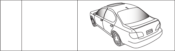
b. Installation Instructions for Vehicles with Aerial-Type Roof-Mounted Antenna.
For
vehicles where the radio antenna is located on the front or rear of the roof of the
vehicle, the FM Extender Antenna should be mounted horizontally on the front or rear
glass below the vehicle antenna, or installed into the vehicle’s headliner, directly
under the vehicle antenna.
If you are installing the FM Extender Antenna on the window glass, attach the
suction cups to the glass under the vehicle antenna in a horizontal orientation.
The wire between the two suction cups should be pulled taut and as straight as
possible, and should not obstruct the driver’s view (see Figure 25).
If you are installing the FM Extender Antenna into the headliner, remove the suction
cups and tuck the wire into the headliner, stretched taut and straight, and centered
directly under the vehicle antenna.
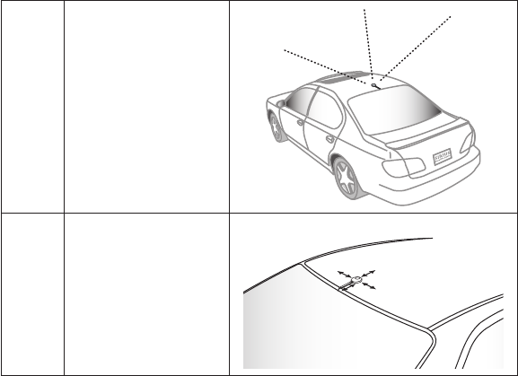
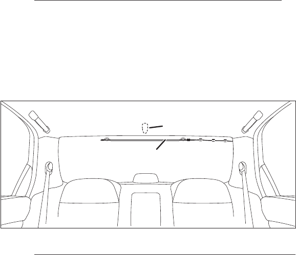
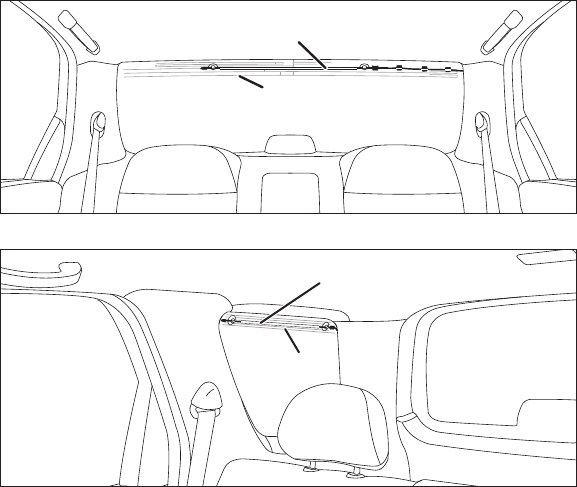
c. Installation Instructions for Vehicles with On-Glass Type Antenna.
For vehicles where the radio antenna is located on the window glass, the FM Extender
Antenna can be mounted horizontally on the glass, directly over the vehicle’s radio
antenna, or installed into the vehicle’s headliner, directly above the vehicle’s antenna.
If you are installing the FM Extender Antenna on the window glass, attach the
suction cups to the glass centered over the vehicle’s radio antenna in a horizontal
•
•
•
Mount FM Extender Antenna on
Rear Windshield Under Roof-Mounted
Vehicle Antenna.
Vehicle Antenna (on Roof)
Figure 25
[ Installation ] 43
orientation. The wire between the two suction cups should be pulled taut and as
straight as possible, and should not obstruct the driver’s view. (See Figures 26 & 27)
If you are installing the FM Extender Antenna into the headliner, remove the suction
cups and tuck the wire into the headliner, stretched taut and straight, and centered
directly above the vehicle’s antenna.
•
Mount FM Extender Antenna on
Rear Windshield Directly Over
Vehicle Antenna
Vehicle Antenna
(Inside Glass)
Mount FM Extender Antenna
on Window Directly Over
Vehicle Antenna
Vehicle Antenna
Figure 26
Figure 27
[ Installation ]
44
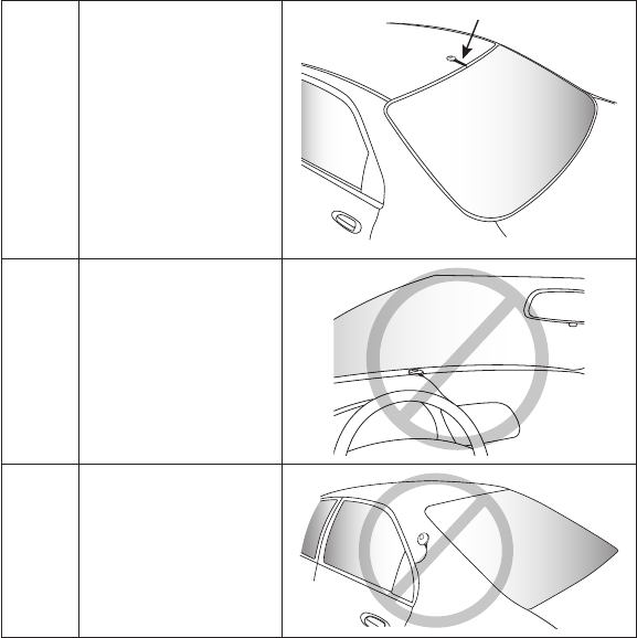
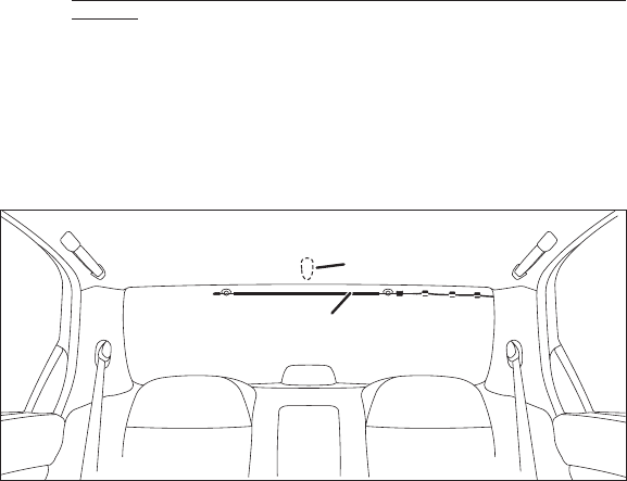
d. Installation Instructions for Vehicles with Shark-Fin Type Roof-Mounted
Antenna. For vehicles where the radio antenna is located on the rear of the roof of
the vehicle, the FM Extender Antenna should be mounted horizontally on the glass
below the vehicle’s antenna, or installed into the vehicle’s headliner, directly under
the vehicle’s antenna.
If you are installing the FM Extender Antenna on the window glass, attach the
suction cups to the glass under the vehicle antenna in a horizontal orientation.
The wire between the two suction cups should be pulled taut and as straight as
possible, and should not obstruct the driver’s view (see Figure 28).
If you are installing the FM Extender Antenna into the headliner, remove the
suction cups and tuck the wire into the headliner, stretched taut and straight, and
centered directly under the vehicle antenna.
•
•
Mount FM Extender Antenna on
Rear Windshield Under Roof-Mounted
Vehicle Antenna.
Vehicle Antenna (on Roof)
Figure 28
[ Installation ] 45
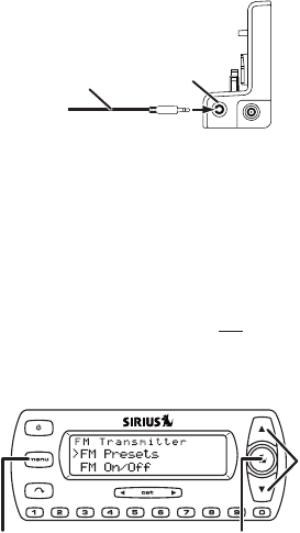
3. Temporarily plug the FM Extender Antenna into the Vehicle dock’s FM OUT connector
(see Figure 29).
4. Tune through your vehicle radio’s FM channels to find an FM channel (between 88.1MHz
and 107.9MHz) that is not broadcasting in your area.
• If you’re not sure which FM channels are not broadcasting in your home or travel cities,
you can also go to http://www.sirius.com/fmchannel and search for a suggested FM
channel based on your zip code.
a. Once you have located an FM channel that is not broadcasting in your area, save it as
a preset on your vehicle radio. This will become your SIRIUS preset.
b. Dock your SIRIUS receiver and turn its power ON. Wait for the Channel Update to
finish before pressing any buttons.
c. Press and hold the MENU button. The Stratus 4’s display will show the FM TRANSMITTER
display (see Figure 30).
FM OUT ANT
FM OUT
Jack
Vehicle Dock
(Right Side)
Cable From
FM Extender Antenna
Figure 29
Select
Button
Channel
UP/DOWN
Buttons
MENU
Button
Figure 30
[ Installation ]
46
d. Use the Channel UP/DOWN buttons to highlight FM PRESETS and press the Select
button. The FM PRESETS screen will appear (see Figure 31, left).
e. Select FM1. The FM1 screen will appear (see Figure 31, right).
Note: FM1 is factory-set to 88.1MHz (indicated by a check-mark). This may not be the
best frequency for your area.
f. Use the Channel UP/DOWN buttons to highlight the same FM frequency that you set your
vehicle’s radio to in Step 4a, on page 45. A check-mark will appear next to the frequency.
g. Press the Select button to set the FM Transmitter frequency and return to the FM
PRESETS screen.
h. Press the MENU button twice to return to the Default screen.
To listen to your SIRIUS radio, turn your SIRIUS radio ON, then turn your vehicle’s FM
radio ON and press the SIRIUS preset you set in Step 2, on page 24. You should now
hear the audio from your SIRIUS radio over your vehicle’s FM radio. If the audio quality is
not satisfactory, try moving the FM Extender Antenna slightly to see if a better signal can
be obtained.
Note: If you have mounted the FM Extender Antenna in the headliner of the vehicle, skip
Step 5.
When you are satisfied with the FM Extender Antenna’s mounting location, remove the
suction cup mounts and peel the backing off the adhesive mounts (see Figure 27).
Permanently adhere the FM Extender Antenna in the same position on the glass
(or A-Pillar), keeping it taut and as straight as possible.
5.
Adhesive Adhesive
Figure 32
Figure 31
[ Installation ] 47
Unplug the FM Extender Antenna from the Vehicle Dock and permanently route its cable
around the vehicle’s passenger compartment to your Stratus 4 Vehicle Dock.
• Use the included self adhesive cable guides (if necessary) to hold the antenna cable in
place until it reaches the weather stripping or moulding at the edge of the window.
• Tuck the cable into the molding and route it around the passenger compartment towards
the Vehicle Dock. Take advantage of any existing cable channels or wiring conduits.
• Take care not pull the cable across sharp edges that could damage it, and keep it away
from areas where it might entangle feet or interfere with the driver’s pedals.
• Coil any excess antenna cable in a location where it can be hidden and then secured.
7. Plug the FM Extender Antenna into the Vehicle Dock’s FM OUT connector. Refer to
Figure 29 on page 45.
6.
[ Installation ]
48
Subscribing to the SIRIUS Service
Before you can listen to the SIRIUS service, you need to subscribe to the SIRIUS Satellite
Radio service. To subscribe, do the following:
Be sure that your SIRIUS Stratus 4 is correctly installed, is properly docked in the Vehicle
Dock, and that the antenna is oriented to receive the SIRIUS signal.
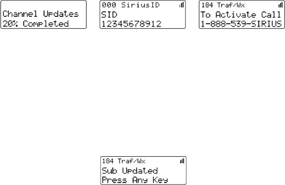
Turn on the Stratus 4. After the startup sequence, it will update the SIRIUS channel line-up (see
Figure 32, left). Wait until the channel updates have completed before pressing any buttons.
Once the channels have been updated, the radio will automatically tune to channel 184
and the display will change to Call 1-888-539-SIRIUS to Subscribe (see Figure 32,
center). You will not be able to listen to any other channels until you activate your SIRIUS
subscription.
Use the Channel UP/DOWN buttons to tune to channel 0 to display your Stratus 4’s
unique 12-digit SIRIUS ID Number (SID). See Figure 32, right.
The SID number is also available on your Stratus 4’s packaging, and may also be accessed
by pressing the MENU button and selecting SIRIUS ID. Write the SID number down.
Have your credit card handy and contact SIRIUS on the Internet at:
https://activate.siriusradio.com/ and follow the prompts to activate your subscription.
You can also call SIRIUS toll-free at: 1-888-539-SIRIUS (1-888-539-7474).
When you have successfully subscribed to the SIRIUS service your Stratus 4 will display
an alert message (see Figure 33). To continue, press the Select button.
You are now ready to begin enjoying SIRIUS Satellite Radio’s digital entertainment, and can
tune to other channels!
1.
2.
3.
4.
•
5.
6.
Figure 32
Figure 33
[ Controls ] 49
Controls
SIRIUS Stratus 4 Front Panel
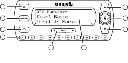
Figure 34 and the section following identify and describe the SIRIUS Stratus 4’s buttons and
controls.
Power Button: Turns the radio’s power ON and OFF.
MENU Button: Accesses Menu Options to make setup and feature changes. Pressing
and holding selects between different preset frequencies used by the built-in wireless
FM transmitter.
Jump Button: Jumps to a pre-selected traffic/weather channel.
Preset/Direct Tune Buttons (0 – 9): Sets and selects preset channels. Also lets you
directly tune channels by entering the channel number.
Category < > Buttons: Navigates through the Category List screen which displays
SIRIUS channel categories.
LCD Display: Displays information about the Stratus 4’s operation and about the program
that is playing.
Channel UP/DOWN Buttons: Navigates through channels and display screens.
Select Button: Selects items highlighted on the display screen. When at the Default
display screen, a press-and-release will display a prompt to enter a channel number.
1.
2.
3.
4.
5.
6.
7.
8.
1
2
3 7
7
8
4
5 6
Figure 34
[ Controls ]
50
Vehicle Dock Reference Guide
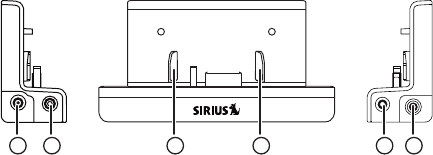
Figure 35 and the section following identify and describe the Vehicle Dock’s features and
connectors.
DC5V Power Connector: Power connection for the supplied cigarette lighter adapter
(see page 32 ).
Audio Out (AUDIO) Connector: Audio output for directly connecting to your vehicle’s
audio system (see pages 33 & 35 ).
Docking Rails: Fit-into slots in the back of the SP5 to secure it while it is docked
(see page 32).
FM OUT Connector: FM output for use with the optional FM Direct Adapter (see page 34).
Antenna (ANT) Connector: Connection for the supplied magnetic antenna (see page 31).
1.
2.
3.
4.
5.
AUDIO
5VDC FM OUT ANT
1 2 433 5
Figure 35
[ Operation ] 51
Operation
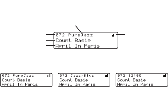
Display Screen Information
Whenever you power your Stratus 4 ON, the previously-selected channel will automatically
begin playing, and the Stratus 4’s display screen will show the currently-tuned channel, the
song or show being played, the artist name and other information. This screen is referred to as
the Default screen in this manual. Figure 36 identifies the information displayed when listening
to a typical broadcast.
You can choose to have the channel name, category name, or the time displayed on the Default
display screen (see Figure 37).
To change the display, press the MENU button, use the Channel UP/DOWN buttons and Select
button to highlight and select DISPLAY OPTIONS > MODE, and then choose the desired display
option. (See MODE, on page 60.)
Song Title
Artist Name
Channel Number Signal Strength
Channel Name
Figure 36
Figure 37
[ Operation ]
52
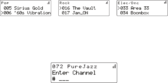
Changing Channels and Categories
Pressing the Channel UP or DOWN button will cause the Stratus 4 to immediately tune to the
next or previous channel.
Pressing the Category < or > button once will display a list of the channels in the current category,
highlighting the currently-tuned channel (see Figure 38). Use the Channel UP/DOWN buttons
to navigate through the list, and press the Select button to choose a selected channel. Press
the Category < or > buttons to scroll through all the different categories (see Figure 38).
Selecting Channels Directly
You can directly tune to any channel by entering its channel number. Momentarily press and
release the Select button. At the display prompt (Figure 39), use the Preset/Direct tune (0 – 9)
buttons to enter the channel’s three-digit number.
Figure 38
Figure 39

[ Operation ] 53
Channel Presets
You can store up to 10 of your favorite channels as presets for quick access by pressing the
0 – 9 buttons.
Storing Channel Presets
To store a favorite channel as a preset, do the following:
Tune the Stratus 4 to the channel you want to store as a preset.
Press and hold for 1 second the numbered preset button (0 – 9) in which you want
to store the channel. You will hear an audible beep and the display will confirm that the
channel has been stored as a preset (see Figure 40).
Note: If the preset button already has a channel stored in it, the newly-stored channel will
replace the original preset.
Selecting Presets
To tune to a preset channel, press and release one of the 0 – 9 buttons. If you press a preset
button in which no channel has been saved, the PRESET EMPTY message will be displayed
(see Figure 41).
1.
2.
Figure 40
Figure 41
[ Operation ]
54
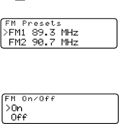
FM Transmitter Presets
If you are using a wireless connection between your SIRIUS Stratus 4 and your vehicle’s audio
system (see page 36), you can easily select between the five different preset FM transmitter
frequencies or select new FM transmitter preset frequencies without having to go through the
Menu Options (see page 57).
To quickly access the FM Transmitter menu, press and hold the MENU button.
If the FM Transmitter is set to ON: Each press-and-hold of the MENU button will switch to the
next preset FM Transmitter frequency (see Figure 42).
If the FM Transmitter is set to OFF: The FM On/Off screen appears (see Figure 43). Use the
Channel UP/DOWN buttons to highlight ON, and press the Select button.
After selecting ON, the FM PRESETS screen will appear. Each press-and-hold of the MENU
button will switch to the next preset FM Transmitter frequency (see Figure 42).
Figure 42
Figure 43
[ Operation ] 55
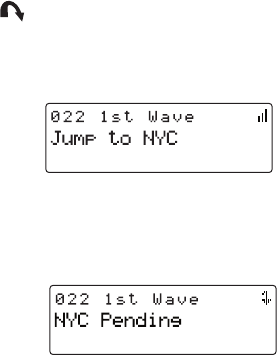
Jump Button
Pressing the Jump button will jump to a traffic/weather channel which you have chosen for your
area. This button allows you to quickly tune the traffic/weather for your area and then tune back
to the original channel by pressing the Jump button again (see Figure 44).
If your traffic/weather report is not immediately available, the display will indicate that a jump
is pending (see Figure 45). Once your local traffic/weather report is ready, the Stratus 4 will
automatically tune to the traffic/weather channel. You may have to wait a few minutes for your
desired report.
Pressing the Jump button while a jump is pending will cancel the jump. Pressing the Jump
button after the Stratus 4 has tuned to the traffic/weather report will return to the channel you
had been listening to immediately prior to pressing the Jump button.
Refer to Jump Settings on page XX for information on configuring the Jump button for
traffic/weather in your area.
Figure 44
Figure 45
[ Menu Options ]
56
Menu Options
Menu Options allows you to set and/or change the various features and settings of your SIRIUS
Stratus 4. Press and release the MENU button to display the MENU OPTIONS screen (see Figure 46).
Use the Channel UP/DOWN buttons to highlight selections in the menu lists and press the Select
button to select them. To exit a menu, press the MENU button. If you don’t make a selection within
10 seconds the Stratus 4 will exit the MENU OPTIONS screen and revert to the last active display
mode. You can exit any Menu Options screen by pressing the MENU button.
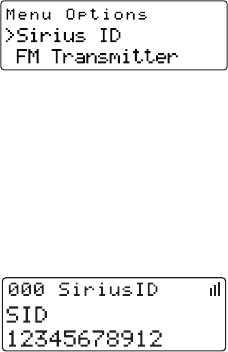
SIRIUS ID
This displays your Stratus 4’s 12-digit SIRIUS ID (SID) number (see Figure 47).
The SID is unique to each SIRIUS radio, and is required to activate your service. We
recommend that you write this number in the space provided near the end of this user guide.
No adjustments are allowed in this mode. To exit, press the MENU button.
Figure 46
Figure 47
[ Menu Options ] 57
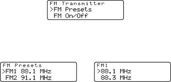
FM Transmitter
The FM Transmitter menu option allows you to enable or disable the Stratus 4’s built-in FM
transmitter, and select up to 5 different preset FM transmitter frequencies (see Figure 48).
FM PRESETS
You can select from the 5 preset FM transmitter frequencies:
1. On the FM TRANSMITTER screen (Figure 48), highlight and select FM PRESETS.
The FM PRESETS screen will appear (see Figure 49, left). Note: You may also enter this
list by pressing and holding the MENU button.
2. Use the Channel UP/DOWN buttons to highlight the FM preset you want (FM1 – FM5),
and press the Select button. The display will show a list of FM frequencies (see Figure 49,
right). The currently-selected frequency for that preset will be highlighted.
3. To select the FM Preset: Press the Select button.
To change the FM Preset’s FM frequency: Use the Channel UP/DOWN buttons to
highlight a different FM frequency, then press the Select button.
To exit, press the MENU button.
Figure 48
Figure 49

[ Menu Options ]
58
FM ON/OFF
You can turn the Stratus 4’s FM transmitter ON and OFF:
1. From the FM TRANSMITTER screen (see Figure 48, on page 57), highlight and select FM
On/Off. The FM ON/OFF screen will appear (see Figure 50).
2. To turn the FM transmitter ON, highlight and select ON; to turn the FM transmitter OFF,
highlight and select OFF.
Press the MENU button to exit.
Figure 50
[ Menu Options ] 59
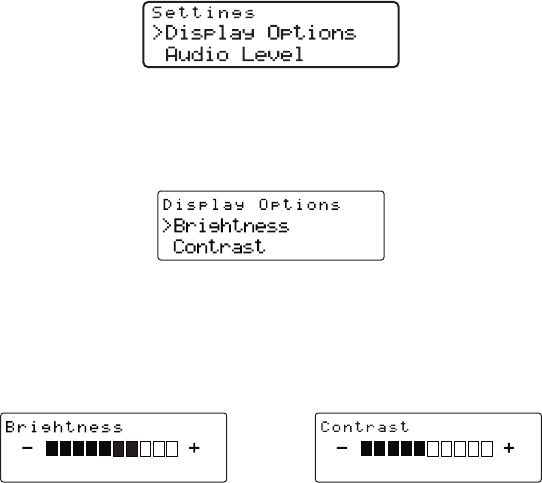
Settings
The SETTINGS menu lets you access the DISPLAY OPTIONS, AUDIO LEVEL, TONES, CLOCK, JUMP
SETTINGS and CHANNEL LOCK menu options (see Figure 51).
Display Options
The Display Options menu (Figure 52) lets you adjust the Stratus 4’s LCD display to improve its
visibility in different lighting conditions, and to display different types of information.
BRIGHTNESS AND CONTRAST
Brightness adjusts the overall intensity of the LCD display to help with viewing in different
lighting conditions. Contrast adjusts the relationship between the background and the text on
the LCD display.
Use the Channel UP/DOWN buttons to adjust the brightness and contrast. The bar graphs will
indicate the change (see Figure 53).
Figure 51
Figure 52
Figure 53
[ Menu Options ]
60
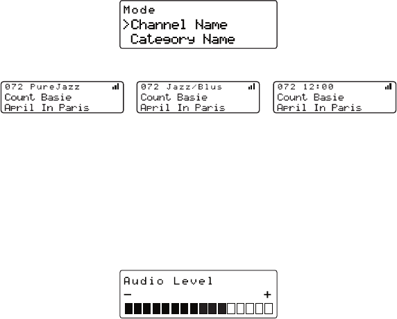
Mode
The MODE screen (Figure 54) lets you change the default display screen to display
either the channel name, category name, or the time. See Figure 55 for examples.
Use the Channel UP/DOWN buttons to select the desired mode and press the Select button
to set your choice.
Audio Level
The AUDIO LEVEL screen lets you use the Channel UP/DOWN buttons to adjust the Stratus 4’s
audio output level (see Figure 56). The bar graph will indicate the change.
Figure 50Figure 54
Channel Name Category Name Clock
Figure 55
Figure 56

[ Menu Options ] 61
Tones
You can select whether to hear an audible confirmation tone as you navigate menus and lists.
To turn the tones on or off, use the Channel UP/DOWN buttons to select your choice and press
the Select button to set your choice (see Figure 57).
Clock
The CLOCK screen (see Figure 58) allows you to setup the clock that appears on the Default
screen, based on the format desired and the time zone in which you reside. The actual time is
provided via the SIRIUS satellite signal, and will automatically update your Stratus 4.
Format
Displays the time in either 12-hour (default) or 24-hour format (see Figure 59).
Figure 57
Figure 58
Figure 59
[ Menu Options ]
62
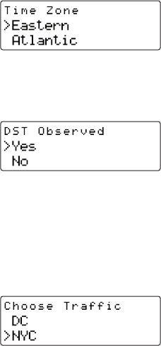
Time Zone
Since the clock adjusts the time automatically, it is important to specify your time zone. Select
your time zone from the list of the available time zones (see Figure 60).
Daylight Savings Time
Select ON if your area observes Daylight Savings Time; select OFF if your area does not (see
Figure 61).
Jump Settings
The Jump menu lets you select which city’s traffic and weather reports the Stratus 4 will provide
when you press the Jump button. Use the Channel UP/DOWN buttons to select a city and
press the Select button to set your choice (see Figure 62).
Figure 60
Figure 61
Figure 62

[ Menu Options ] 63
Channel Lock
Your SIRIUS Stratus 4 has the ability to lock channels you do not want others (such as children)
to access without your permission. Locked channels will not appear on the Channel List screen,
or when browsing channels with the Channel UP/DOWN buttons. When the anyone tries to
access a locked channel using the Direct Tuning function (see page 52), an ENTER CODE screen
will be displayed and the channel won’t be accessed until the correct code is entered.
Locking and Unlocking Channels
Select the CHANNEL LOCK menu option. The CHANNEL LOCK screen will appear
(see Figure 63, left).
Select LOCK/UNLOCK. You will need to enter the lock code to proceed. Refer to Changing
the Lock/Unlock Code, on page 64 for information on how to set the lock code.
Once you enter the lock code the LOCK/UNLOCK screen will appear (see Figure 63, right).
Use the Channel UP/DOWN buttons to highlight the channel you wish to lock or unlock
from the channel list. Pressing the Select button will either add a padlock icon next to the
channel name to indicate that the channel will be locked, or unlock a locked channel by
removing the padlock icon.
1.
2.
3.
Figure 63

[ Menu Options ]
64
Changing the Lock/Unlock Code
The first time you access the LOCK/UNLOCK menu, you must enter the default lock code. The
default lock code is 0 0 0 0. You can keep this code or change it. To change the lock code:
Select the CHANNEL LOCK menu option. The CHANNEL LOCK screen will appear
(see Figure 63, left, on page 63)
Select the EDIT CODE menu option. The ENTER CODe screen will appear (see Figure 64).
Enter the default lock code (0 0 0 0) or the current lock code if you have changed it from
the default code. (If you enter the wrong code, a message will be displayed indicating that
the wrong code has been entered.)
The NEW CODE prompt will be displayed. Enter your new four digit code using the
0 – 9 number buttons. You will then be prompted to enter the new code again to confirm.
When the new lock code is confirmed, the lock code is changed.
You can use this same procedure to change the lock code again after you have changed it from
the default code.
Note: If you have forgotten your Channel Lock code, call SIRIUS Customer Service for help.
1.
2.
3.
4.
5.
Figure 64
[ Menu Options ] 65
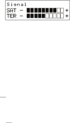
Signal
When using the optional Home Docking Station or Boombox indoors, it is important to aim the
antenna for maximum signal reception. The SIGNAL screen (see Figure 65) visually shows the
strength of the satellite and terrestrial signals being received by the Stratus 4. (Refer to the Home
Docking Station installation guide for more information about properly orienting the antenna.)
The SAT bar graph indicates the strength of the satellite signal strength; the TER bar graph
indicates the strength of the terrestrial signal strength (if available).
Factory Default
The Factory Default menu option will restore most every feature of the radio to the original fac-
tory settings. The following is a list of all features affected by the Factory Default option:
All Channel Presets are cleared
Radio set to Normal Tuning Mode
Display brightness set to 50%
Display Contrast set to 50%
FM Transmitter set to ON
FM Transmitter Preset #1 set to 88.1 MHz
Jump setting is cleared
Top line display mode set to Channel Name
Audio level set to -3dB
Confirmation Tone set to ON
Note that the Parental Control feature is not affected by the Factory Default option. If a code
has been set for the Parental Control feature, the code will not be reset by the Factory Default
•
•
•
•
•
•
•
•
•
•
Figure 65

[ Menu Options ]
66
feature, preventing someone from circumventing the Channel Lock feature. Channels which
have been locked will remain locked.
To activate the Factory Default feature, and restore the above features to their factory defaults,
do the following:
Highlight and select FACTORY DEFAULT from the Menu Options screen. The RESTORE?
screen will appear (see Figure 66, left).
Highlight and select YES to restore the above settings to the their factory default settings,
or select NO to leave them as-is and return to the MENU OPTIONS screen.
If you select YES, a confirmation screen appears (see Figure 66, right). Use the Channel
UP/DOWN buttons to select YES to restore all settings to the settings from the factory, or
select NO to leave them as-is and return to the Menu Options menu.
If you select YES, the Stratus 4 will restore the original factory settings (see Figure 128).
When the Restore is complete, the Stratus 4 tune to Channel 184 (the SIRIUS pre-
view channel) and display CALL 1-888-539-SIRIUS TO SUBSCRIBE. Your Stratus 4 is still
subscribed to the SIRIUS service, and you can tune to any channel that hasn’t been
locked using the Channel Lock feature.
1.
2.
3.
4.
5.
Figure 66
Figure 66

[ Troubleshooting ] 67
Troubleshooting
Symptom Solution
The Stratus 4 does not
power ON
Blown fuse, or the power cable is not properly connected.
• Check for a bad fuse and check power cable connection
Display reads:
No Antenna
The satellite antenna is not connected to the radio.
• Check the satellite antenna connection to the radio.
Display reads:
Acquiring Signal
No satellite signal is being received.
• Check for obstacles over or around the satellite antenna.
• Change the vehicle location to eliminate nearby obstacles
(bridges, overpasses, tress, buildings, etc.).
Audio static or loss of
clarity
The FM frequency contains static.
• Locate a quiet FM frequency on your vehicle radio and set the FM
transmitter frequency of the SIRIUS radio to match.
• If using the Vehicle Dock AUDIO OUT connector, check the cable
connections.
No sound The audio cables are not connected, or the FM radio is set to the
wrong frequency.
• Check the audio cables at the SIRIUS radio and the vehicle’s
audio system.
• Tune the vehicle’s FM radio to the same FM frequency the SIRIUS
FM transmitter is tuned.
[ Optional Accessories ]
68
Optional Accessories
The following optional accessories are available for purchase from your SIRIUS retailer to
maximize your SIRIUS experience:
SUBX1 SIRIUS Plug and Play Universal Boombox
The SUBX1 SIRIUS Plug and Play Universal Boombox is a portable docking station and audio
system for use with the SIRIUS radio. With the built-in amplifier and speakers, the boombox
delivers rich powerful sound indoors or outdoors, and features an auxiliary input for other audio
devices,
Included with the boombox is an adjustable indoor/outdoor windowsill antenna with 20’ of cable
and an AC adapter.
SUPH1 SIRIUS Universal Plug and Play Home Kit
The SUPH1 SIRIUS Universal Plug and Play Home Kit is a compact docking cradle that posi-
tions the radio for easy viewing and operation. Designed for quick and easy self-installation, it
includes all necessary cabling to connect your SIRIUS radio to your home audio system.
The kit includes a compact tabletop/desktop docking cradle with FM output for wireless con-
nectivity, an audio cable for connection to any stereo bookshelf system, an adjustable indoor/
outdoor windowsill antenna with 20’ of cable, and an AC Adapter.
SUPV1 SIRIUS Universal Plug and Play Vehicle Kit
The SUPV1 SIRIUS Universal Plug and Play Vehicle Kit is a compact docking cradle that posi-
tions the radio for easy wiring, viewing, and operation in an additional vehicle. Designed for
quick and easy self-installation, it provides several mounting options and includes all necessary
cabling to connect your SIRIUS radio to your vehicle audio system.
The SUPV1 SIRIUS Universal Plug and Play Vehicle Kit will work with the Sportster 4 and most
new SIRIUS plug and play radios.
The kit includes a mobile docking cradle, a suction cup vehicle mount, a vent mount, a cigarette
lighter adapter, and a magnetic antenna with 21’ of cable.
[ Optional Accessories ] 69
FM Direct Adapter
The FM Direct Adapter accessory redirects your vehicle’s FM antenna signal when listening to
your SIRIUS radio using your vehicle’s AM/FM radio. When the SIRIUS radio is powered on
the FM Direct Adapter automatically redirects the vehicle’s FM antenna signal away from the
vehicle’s AM/FM radio, reducing any interference which might be present from FM radio sta-
tion broadcasts. When the SIRIUS radio is turned off, the FM antenna signal is automatically
redirected back to the vehicle’s AM/FM radio. (Product number 14100.)
[ Specifications ]
70
Specifications
Satellite Frequencies . . . . . . . . . . . . . . . . . . . . . . . . . . . . . . . . . . . . . .2322.293/2330.207 MHz
Terrestrial Frequencies . . . . . . . . . . . . . . . . . . . . . . . . . . . . . . . . . . . . . . . . . . . . . 2326.250MHz
Radio Power Requirements . . . . . . . . . . . . . . . . . . . . . . . 4.9 – 5.6 Volts, Negative Ground, DC
Audio Output . . . . . . . . . . . . . . . . . . . . . . . . . . . . . . . . . . . . . . . . . . . .550mVrms (+/- 50mVrms)
Total Harmonic Distortion (THD) . . . . . . . . . . . . . . . . . . . . . . . . . . . . . . . . . . . . . . . . . . . . <0.2%
Signal-to-noise (S/N) . . . . . . . . . . . . . . . . . . . . . . . . . . . . . . . . . . . . . . . . . . . Greater than 73dB
Fuse Requirement . . . . . . . . . . . . . . . . . . . . . . . . . . . . . . . . . . . . . . . . . . . . . . . . . . . . . . 2A ATC
Radio Dimensions (Length x Width x Depth). . . . . . . . . . . . . . 114.3mm x 48.26mm x 15.24mm
(4.5” x 1.9” x 0.6”)
Radio Weight . . . . . . . . . . . . . . . . . . . . . . . . . . . . . . . . . . . . . . . . . . . . . . . . . . . . . 85.0g (3.0 oz.)
Cigarette Lighter Adapter Power Requirements . . . . . . . . . .9 –16 Volts, Negative Ground, DC
Antenna Type . . . . . . . . . . . . . . . . . . . . . . . . . . . . . . . . . . . . . . . . . . . . . . . Low Profile Magnetic
Antenna Cable Length . . . . . . . . . . . . . . . . . . . . . . . . . . . . . . . . . . . . . . .21’ (single micro-cable)
Antenna Connector Type . . . . . . . . . . . . . . . . . . . . . . . . . . . . . . . . . . . . . . . . . SMB (right-angle)
Audio Out Interface . . . . . . . . . . . . . . . . . . . . . . . . . . . . . . . . . . . . . . . 1/8” / 3.5mm Stereo Jack
FM Out Interface . . . . . . . . . . . . . . . . . . . . . . . . . . . . . . . . . . . . . . . . . . . . . . . . . . . . 2.5mm Jack
Note: Features and Specifications are subject to change without notice.
[ Warranty ] 71
Warranty
12 Month Warranty
SIRIUS Satellite Radio Inc. (the “Company”) warrants to the original retail purchaser of this product
that should this product or any part thereof, under normal use and conditions, be proven defective in
material or workmanship within 12 months from the date of original purchase, such defect(s) will be
repaired or replaced with new or reconditioned product (at the Company’s option) without charge for
parts and repair labor. To obtain repair or replacement within the terms of this Warranty, the product
is to be delivered with proof of warranty coverage (e.g. dated bill of sale), specification of defect(s),
transportation prepaid, to the location shown below under WARRANTY RETURN.
This Warranty does not extend to the elimination of externally generated static or noise, to correction
of antenna problems, to costs incurred for installation, removal or reinstallation of the product, or to
damage to tapes, compact discs, speakers, accessories, or vehicle electrical systems.
This Warranty does not apply to any product or part thereof which, in the opinion of the Company, has
suffered or been damaged through alteration, improper installation, mishandling, misuse, neglect, ac-
cident, or by removal or defacement of the factory serial number/bar code label(s). THE EXTENT OF
THE COMPANY’S LIABILITY UNDER THIS WARRANTY IS LIMITED TO THE REPAIR OR REPLACE-
MENT PROVIDED ABOVE AND, IN NO EVENT, SHALL THE COMPANY’S LIABILITY EXCEED THE
PURCHASE PRICE PAID BY PURCHASER FOR THE PRODUCT.
This Warranty is in lieu of all other express warranties or liabilities. ANY IMPLIED WARRANTIES,
INCLUDING ANY IMPLIED WARRANTY OF MERCHANTABILITY, SHALL BE LIMITED TO THE DURA-
TION OF THIS WRITTEN WARRANTY. ANY ACTION FOR BREACH OF ANY WARRANTY HEREUN-
DER INCLUDING ANY IMPLIED WARRANTY OF MERCHANTABILITY MUST BE BROUGHT WITHIN
A PERIOD OF 48 MONTHS FROM DATE OF ORIGINAL PURCHASE. IN NO CASE SHALL THE
COMPANY BE LIABLE FOR ANY CONSEQUENTIAL OR INCIDENTAL DAMAGES FOR BREACH OF
THIS OR ANY OTHER WARRANTY, EXPRESS OR IMPLIED, WHATSOEVER. No person or represen-
tative is authorized to assume for the Company any liability other than expressed herein in connection
with the sale of this product. Some states do not allow limitations on how long an implied warranty
lasts or the exclusion or limitation of incidental or consequential damage so the above limitations or
exclusions may not apply to you. This Warranty gives you specific legal rights and you may also have
other rights which vary from state to state.
WARRANTY RETURN: To obtain repair or replacement within the terms of this Warranty, please return
product to an authorized retailer or call Customer Service at 1-800-869-5590; proof of purchase and
description of defect are required. Products to be returned to an approved warranty station must be
shipped freight prepaid.

[ SIRIUS ID ]
72
SIRIUS ID
Write down the SIRIUS ID (SID) of your SIRIUS Stratus 4 in the space provided below.
SID: _______________________________________
[ Notes ] 73

SIRIUS Customer Service: 1-888-869-5590
customercare@sirius-radio.com
SIRIUS Satellite Radio Inc.
1221 Avenue of the Americas
New York, NY 10020
1-888-539-7474
http://www.sirius.com

Stratus 4 User Guide (062907a)
00.ABCD1.001
sirius.com
Sirius Satellite Radio Inc.
1221 Avenue of the Americas
New York, NY 10020
800.869.5590