Humax T9 Wi-Fi Router User Manual
Humax Co., Ltd. Wi-Fi Router
UserManual.wiki
>
Humax
>
T9 User Manual
>
User Manual
Contents
1.
User Manual
2.
Users manual
User Manual
Navigation menu
Upload a User Manual
Namespaces
Wiki Guide
HTML
PDF
Info
Views
User Manual
Discussion / Help
Navigation

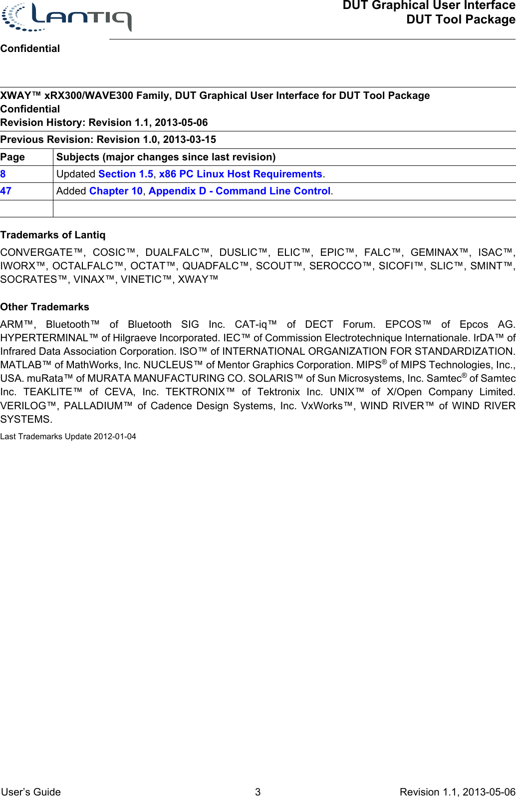
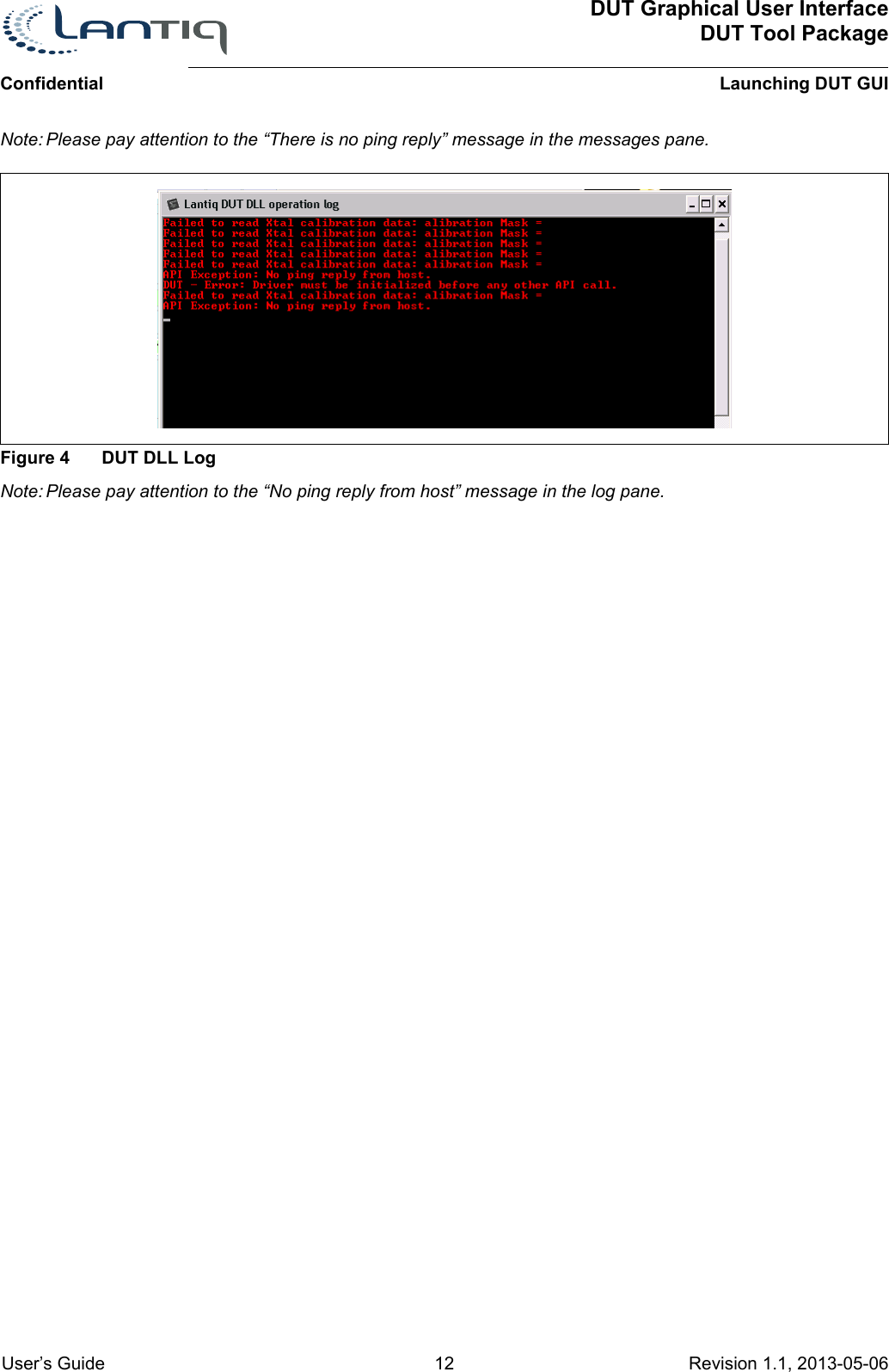
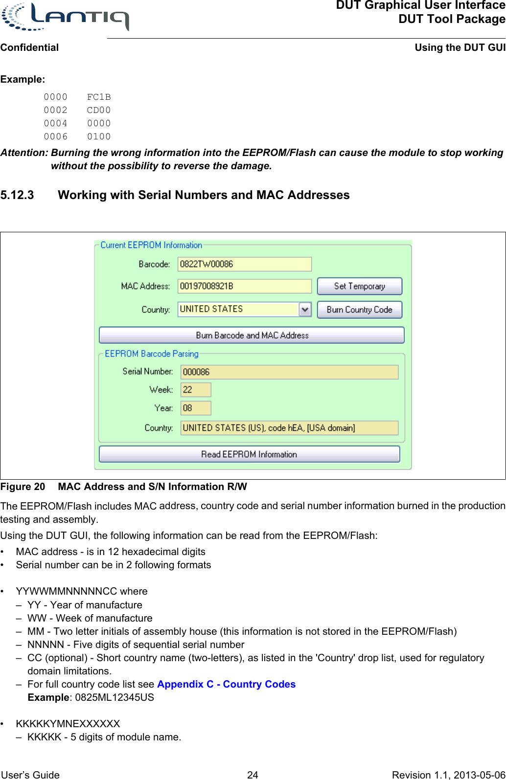
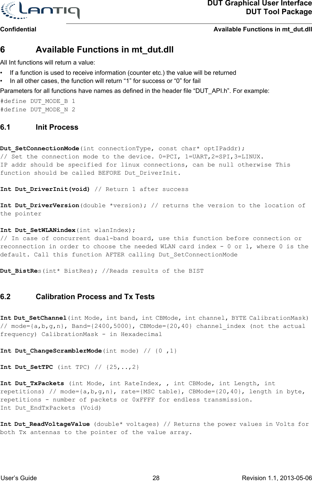
![ConfidentialDUT Graphical User InterfaceDUT Tool PackageIntroduction User’s Guide 8 Revision 1.1, 2013-05-06 1 Introduction1.1 PurposeThis user guide explains how to use the DUT GUI application. The application is used for hardware development purposes and evaluations based on Lantiq's WiFi MIMO technology.1.2 About the Test Driver and the DUT GUI ApplicationThe DUT GUI is an application used to help hardware and RF designers test and verify the behavior of their design based on Lantiq's WiFi solution.DUT GUI uses a specially designed test driver with the firmware that uses all HW and PHY level algorithms. The driver also allows transmission and receiving without the limitations of the IEEE 802.11n standard [4].The DUT GUI includes an API to control the WiFi functionality (mt_dut.dll). The API can be used to control the DUT (Device Under Test) from an external application.Together with wireless LAN test equipment maker LitePoint, Lantiq have integrated this dll into LitePoint's IQFact Design Verification Test (DVT) software. IQFact is a comprehensive set of WiFi physical layer transmitter and receiver tests utilizing a large set of channels, data rates and channel bandwidths. The tool allows you to verify assembly in the production line with a vast test coverage in a short test time1.3 Content of the Installation KitThe installation package for the DUT GUI installs the following items onto your computer:• DUT GUI Core• ActivePerl application - Perl interpreter (used for TCP/IP mode)• Release Notes [5]• User’s Guide (= this document)Note: Contact Lantiq for the latest application version and installation instructions.1.4 Supported InterfacesThe DUT GUI application allows you to control the WiFi chipset through the following interface:• TCP/IP - Control the chipset when it is assembled on a Linux based host. In order for the DUT GUI to work, the host should contain operational driver firmware. The following Host and Linux versions are supported:• Lantiq's Universal Gateway (UGW) software1.5 x86 PC Linux Host RequirementsThe DUT system provides following requirements to the x86 Linux host in order to operate properly:1. Microsoft® Windows® XP SP 3.0 and .NET Framework 2.0 (min. requirement)2. Support for Microsoft® Windows® 7, 32/64 bit3. OS login/password required is root/wlan4. This may be changed by editing the linux_hosts.txt file in the DUT's installation directory, with a new username/password to be specified in its [PC] section.5. Tftp client package must be installed.](https://usermanual.wiki/Humax/T9.User-Manual/User-Guide-3606265-Page-8.png)
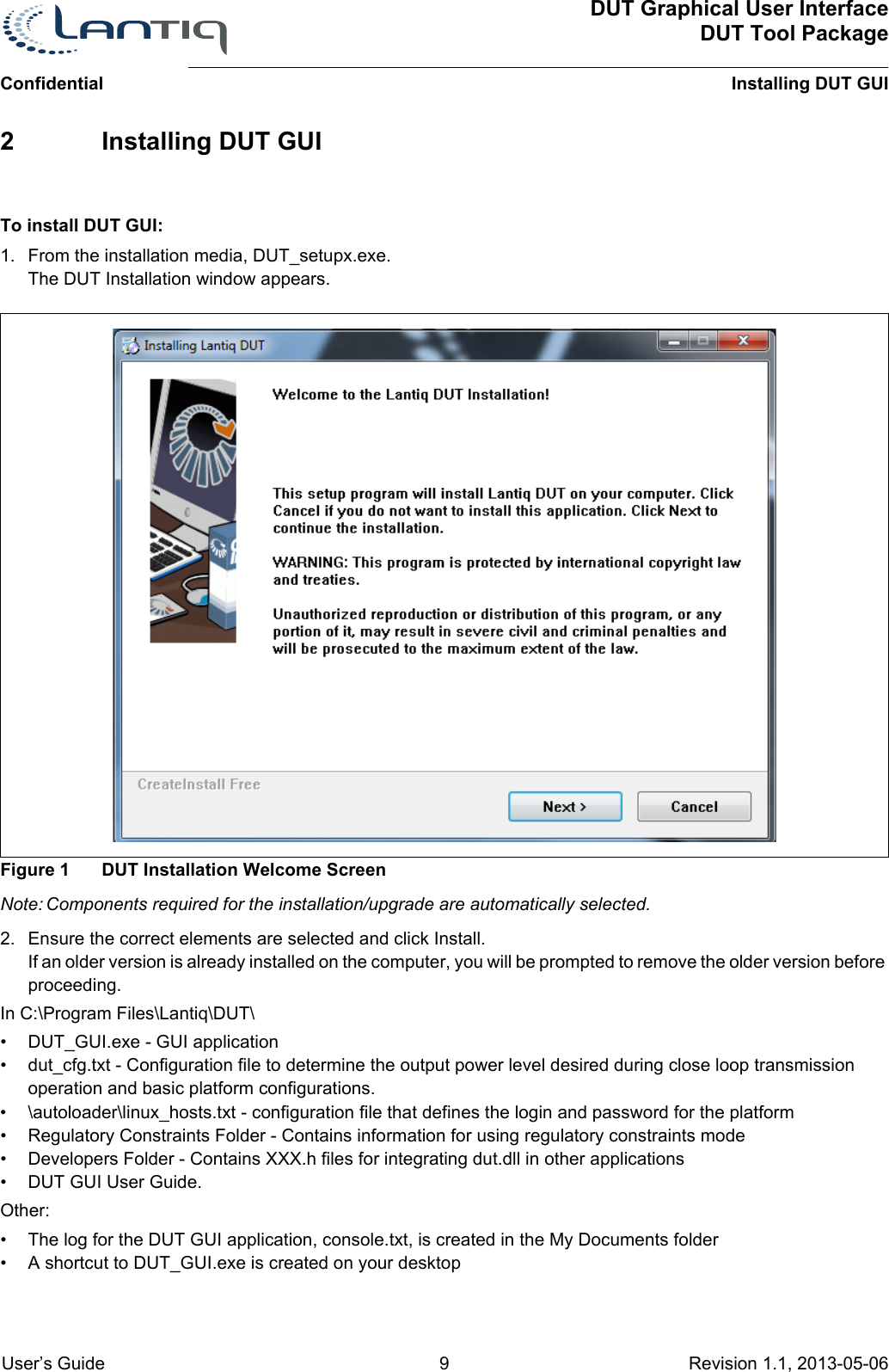
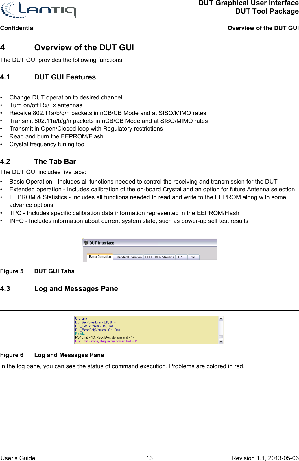
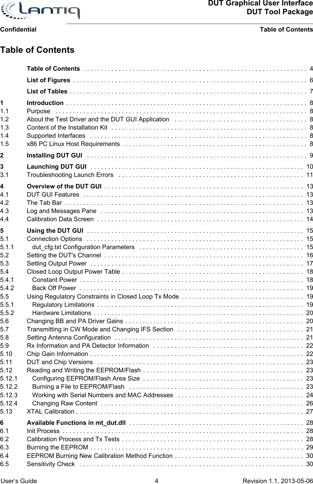
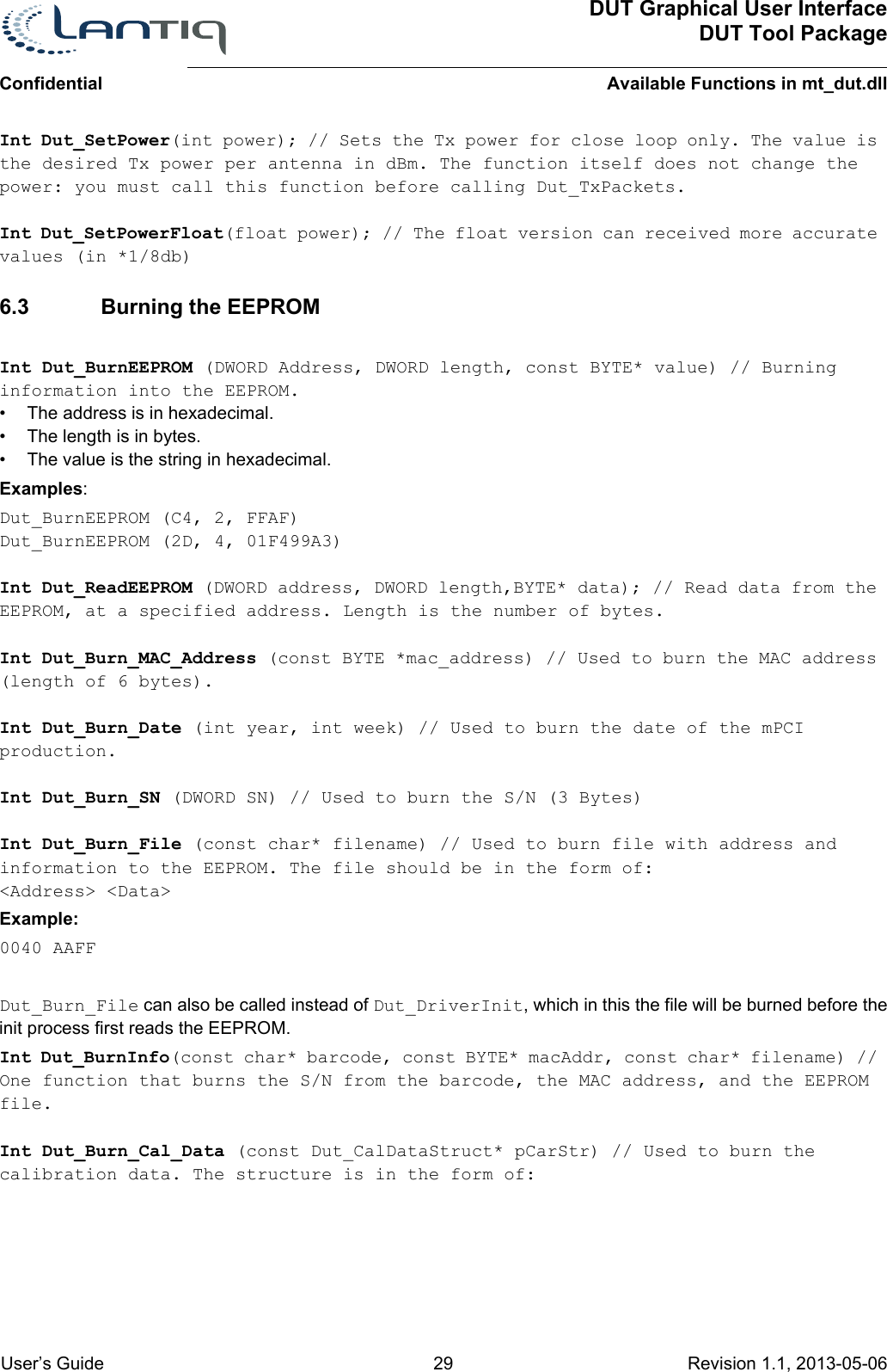
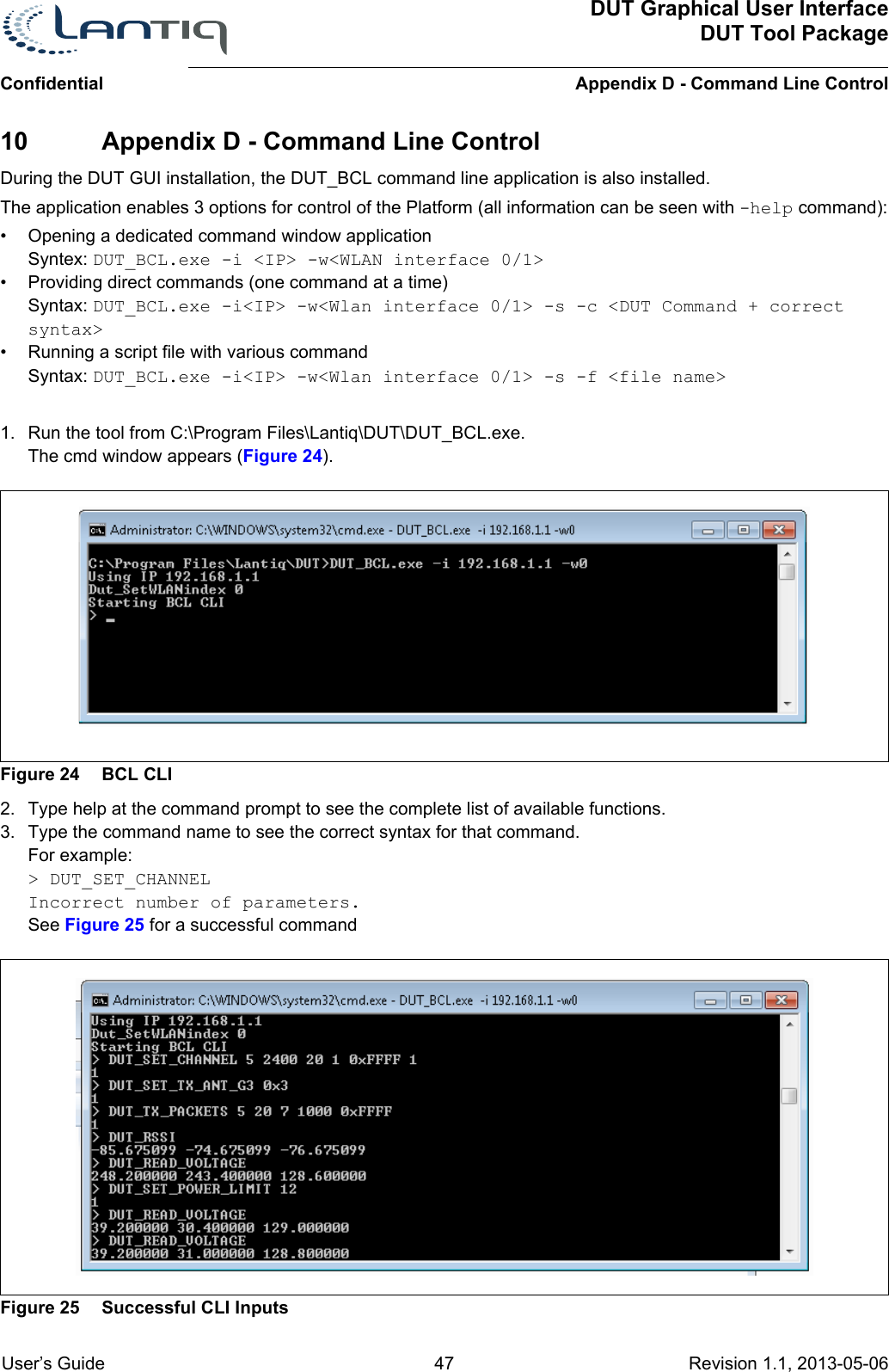
![ConfidentialDUT Graphical User InterfaceDUT Tool PackageUsing the DUT GUI User’s Guide 16 Revision 1.1, 2013-05-06 For example: XTAL_CAL_BIAS = 70 should be used for TXC part.Non-Volatile memory type NV_MEMORY_TYPE0 = 1 // Wlan0 memory typeNV_MEMORY_TYPE1 = 1 // Wlan1 memory typeSelect the memory type used for storing HW related data.1 - eeprom, 2 - flash, 3 - efuseFast OperationFAST_RESTART_METHOD = 10 - Regular Mode1- Fast Restart modeNote:1. Other parameters in dut_cfg.txt are used for debug and should not be modified.2. In case improper hardware type was chosen, it may be required to reboot the DUT host (system to which the device is connected) before reconnection.5.2 Setting the DUT's ChannelFigure 8 Channel Setting and Transmission ScreenWhen the DUT GUI is initialized, it sets the DUT to a channel according to the last run. You can select different parameters and set the DUT's channel using the following options:• PHY Type - Used to select the operation band. PHY type also depends on the type of packets the DUT will transmit. However, if a PHY type of 2.4 Ghz is chosen (for example - 802.11b [2] ) the DUT will also receive and analyze 802.11g and 802.11n packets.• Spectrum BW (Band width) - Dictates the spectrum bandwidth of the transmission:– Non-channel Bonding (nCB) = 20 Mhz– Channel Bonding (CB) = 40 Mhz](https://usermanual.wiki/Humax/T9.User-Manual/User-Guide-3606265-Page-16.png)
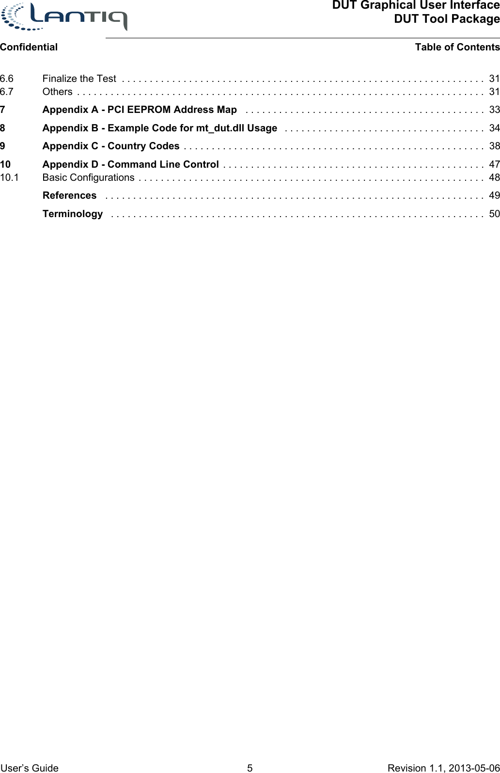
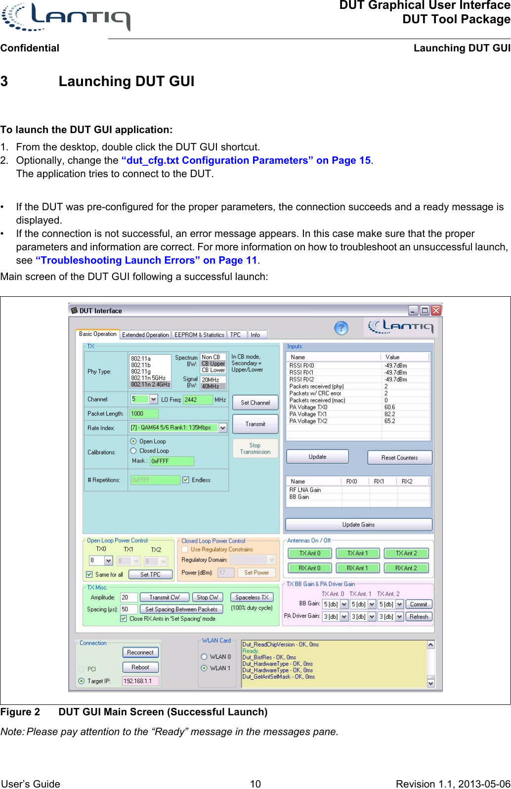
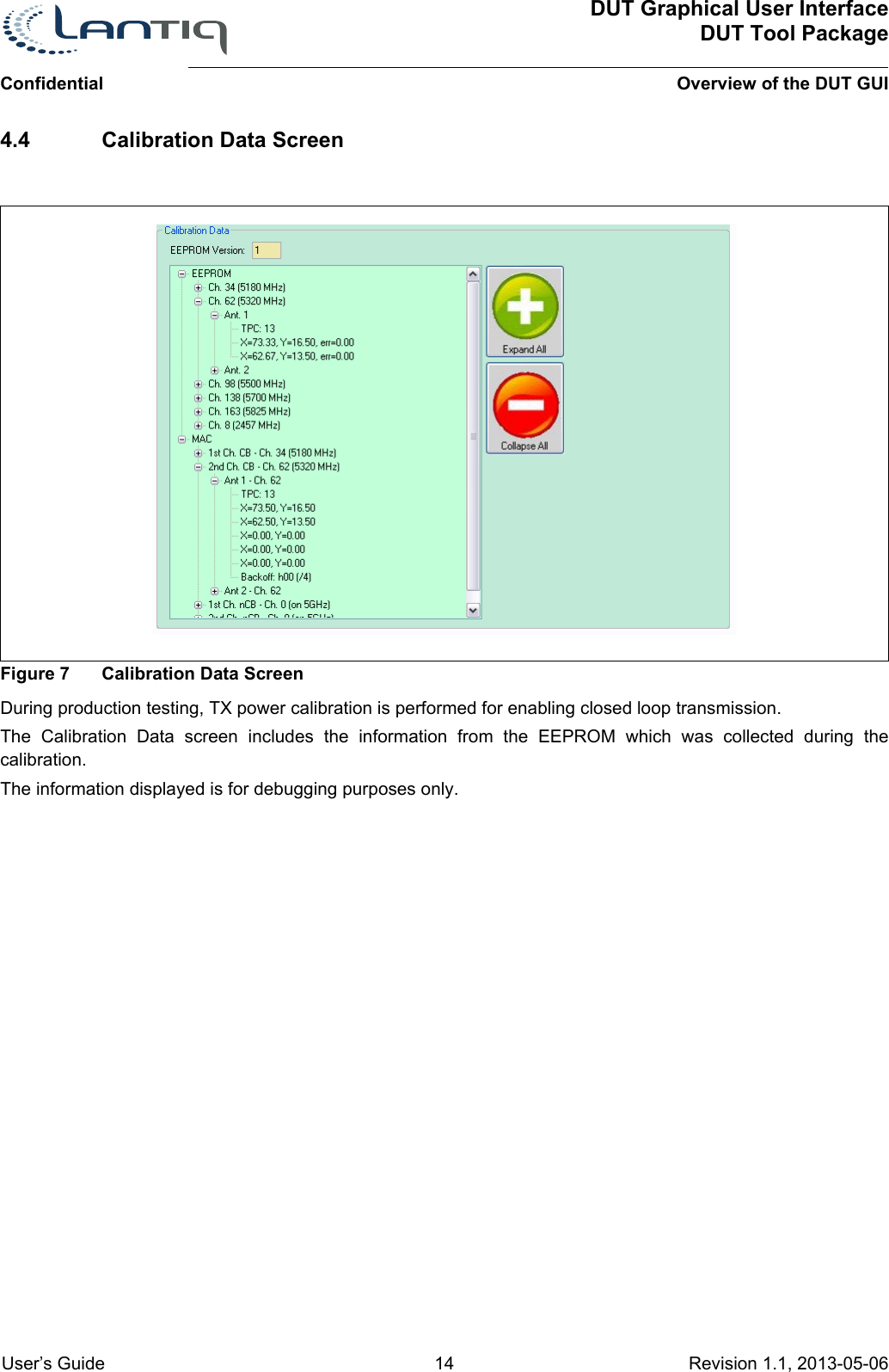
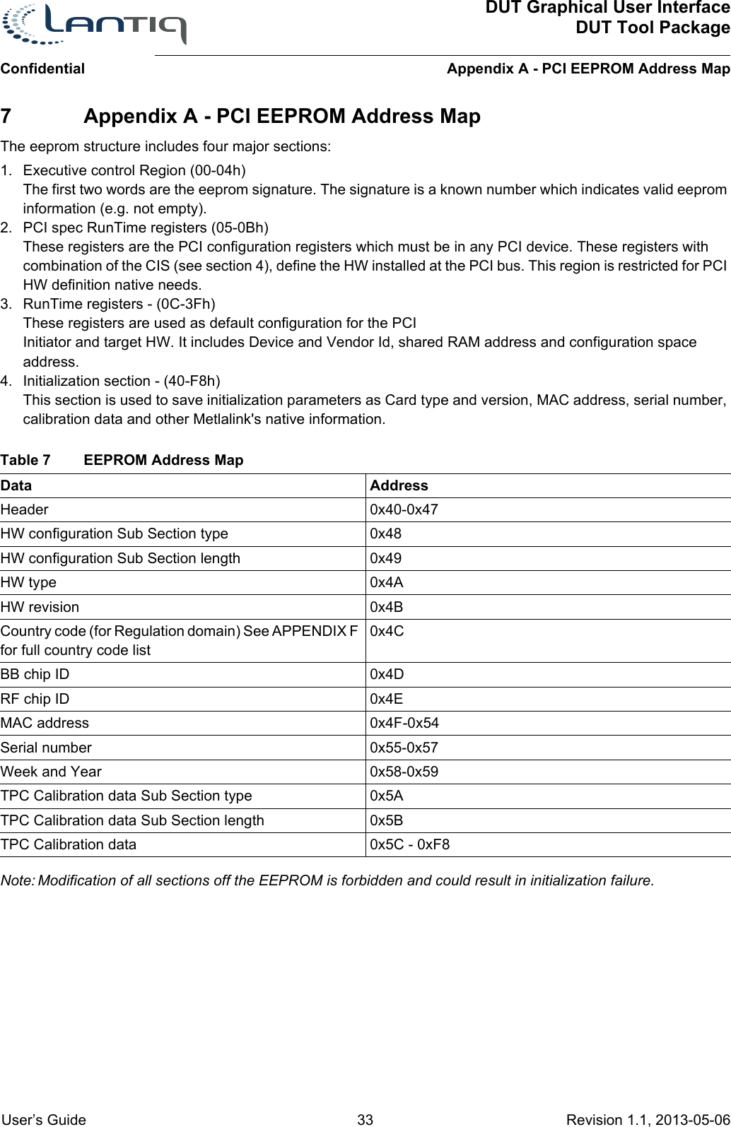
![DUT Graphical User InterfaceDUT Tool PackageUsing the DUT GUIConfidential User’s Guide 17 Revision 1.1, 2013-05-06 If CB is used, the selected channel is the primary channel and you need to choose if the secondary channel will be on the lower or upper side of the primary channel. The DUT GUI automatically calculates the actual frequency of the DUT's LO according to the channel, the BW, and the location of the secondary channelFigure 9 Example of Primary and Secondary Channel Selection in CB Mode• Signal BW - When the 40Mhz spectrum BW is chosen, you can choose between CB (40 MHz) Tx or SSB (single side band) transmission.– In SSB mode, all Tx and Rx filters are on 40 MHz BW, LO is according to 40 MHz transmission but the actual transmitted signal is only in one side of the LO (according to the location of the primary channel)– The difference from the previous option of 20MHz is the location of the signal in comparison to the LO and the filters used. • Channel - Select a channel according to the 802.11n standard definition of channel. LO Frequency will automatically be calculated according to BW definitions.• Byte length - The packet length in bytes. The maximum length is 1570 bytes.• Rate index - According to the MCS table at the 802.11a/b/g/n standards [1]/[2]/[3]/[4]. The list of available rate indexes will be according to the protocol type chosen.• Calibration mask - This influences the initial calibration inside the RF chip after setting channel. The value should be set to 0xFFFF.• Repetitions - How many times the packet should be transmitted.Note: 0xFFFF (65535 in Decimal) = endless transmission• Set Channel button - To instruct the DUT to change channel:– a.Set all the parameters.– b.Click Set Channel. When changing channel all transmissions will be stopped.• Transmit button - To instruct the DUT to start transmitting:– a.Set all the parameters.– b.Click Transmit. • Stop Transmission button - Use this to instruct the DUT to stop transmitting (only available when DUT is in Transmit mode).5.3 Setting Output PowerFigure 10 Open Loop Tx Setting](https://usermanual.wiki/Humax/T9.User-Manual/User-Guide-3606265-Page-17.png)
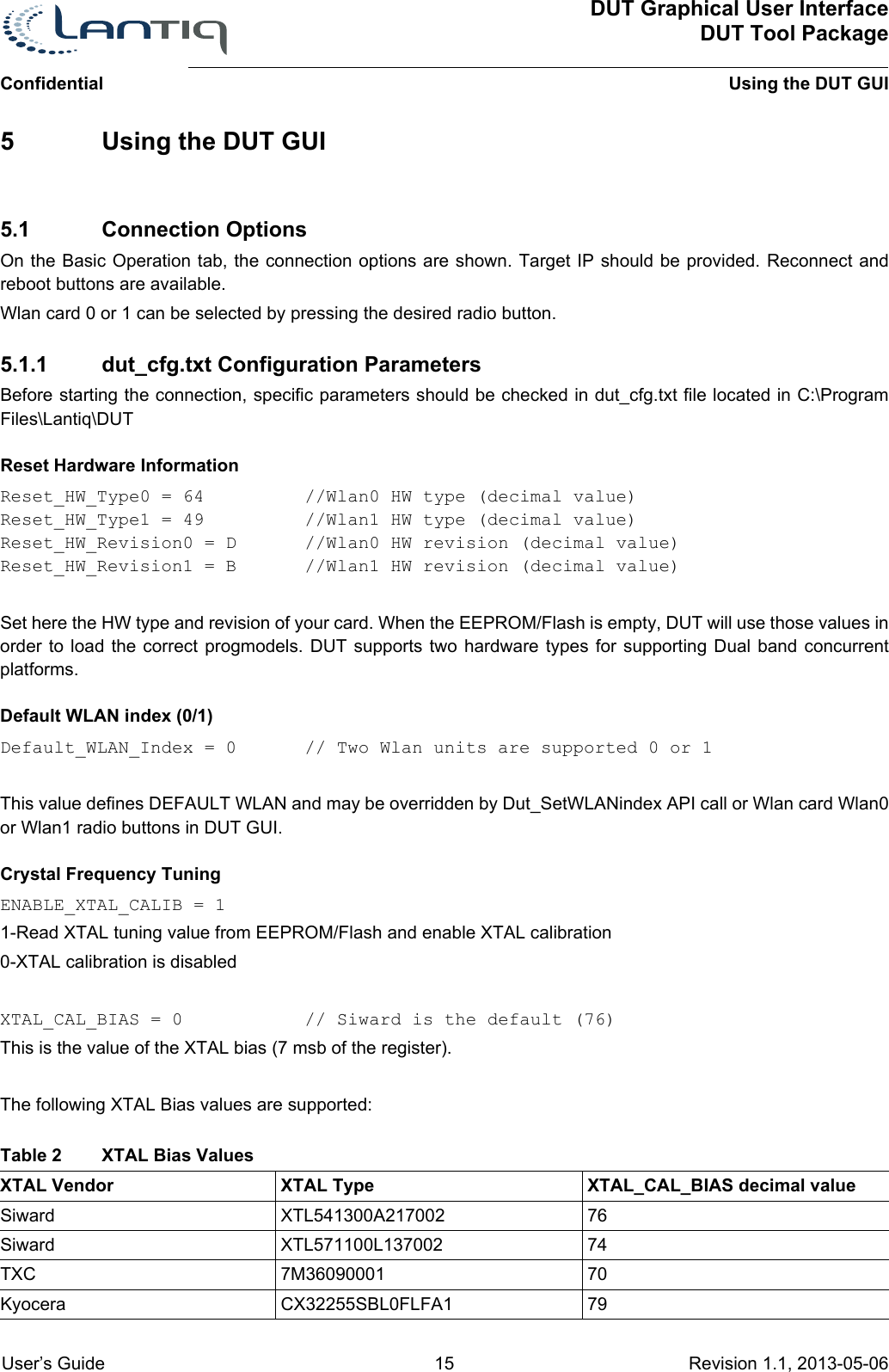
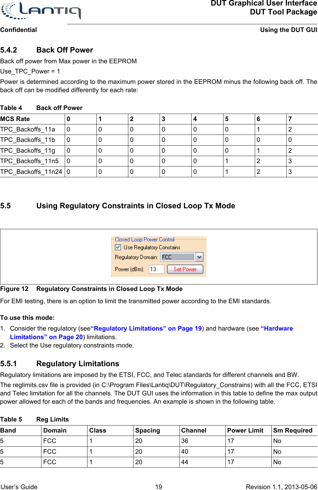
![ConfidentialDUT Graphical User InterfaceDUT Tool PackageUsing the DUT GUI User’s Guide 18 Revision 1.1, 2013-05-06 When transmission is used, you can select several standard and special configurations:• Set TPC - This option is only available in open loop (see Calibration Mask details in “Setting the DUT's Channel” on Page 16.TPC is one of the gain controls of the RF chip. Enter 1, to select transmission with the highest power, any number greater than 2 will lower the output power. The maximum value for TPC is 30 (lowest power). You can decide whether to apply the same TPC value to both transmitters or set independent values for each transmitter.The output power in open loop mode can be changed before or during transmission.5.4 Closed Loop Output Power TableFigure 11 Closed Loop Tx Setting• Set Tx power - In a closed loop transmission (see Calibration Mask details in “Setting the DUT's Channel” on Page 16, power is set automatically using pre-calibrated information stored in the EERPOM/flash. The information is stored in the EEPROM/flash during the TPC calibration method implemented by Litepoint's IQFact application.• The Tx output power is configured automatically according to the rate (see tables below). • Output power in closed loop can be changed before or during transmission.• Close loop power can be set in 1/8 dB resolution example 16.125 dBm, 16.875 dBm etc.• Power table according to the rate is found and can be adjusted in the file: dut_cfg.txt which is located in C:\Program Files\Lantiq\DUT.• There are two options to set the default power per rate. Both are configured using the Use_TPC_Power parameter option in the dut_cfg.txt file: Constant Power and “Back Off Power” on Page 19.5.4.1 Constant PowerUse_TPC_Power = 0Power is determined according to the following table:MCS Rate 01234567Const_Power_11a 17 17 16 15 15 15 15 15Const_Power_11b 19 19 19 19 19 19 19 19Const_Power_11g 19 19 18 18 17 17 17 17Const_Power_11n5 17 16 16 15 15 15 15 15Const_Power_11n24 18 18 17 17 17 17 17Note: For 802.11n [4], rates 8-15 have the same power as rates 0-7.Table 3 Constant Power](https://usermanual.wiki/Humax/T9.User-Manual/User-Guide-3606265-Page-18.png)
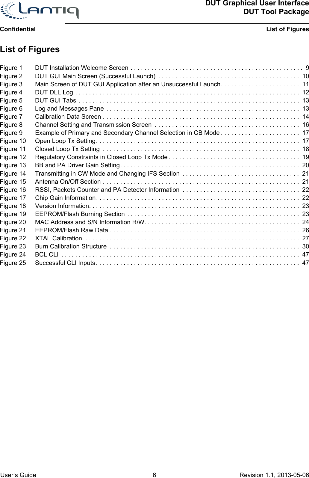
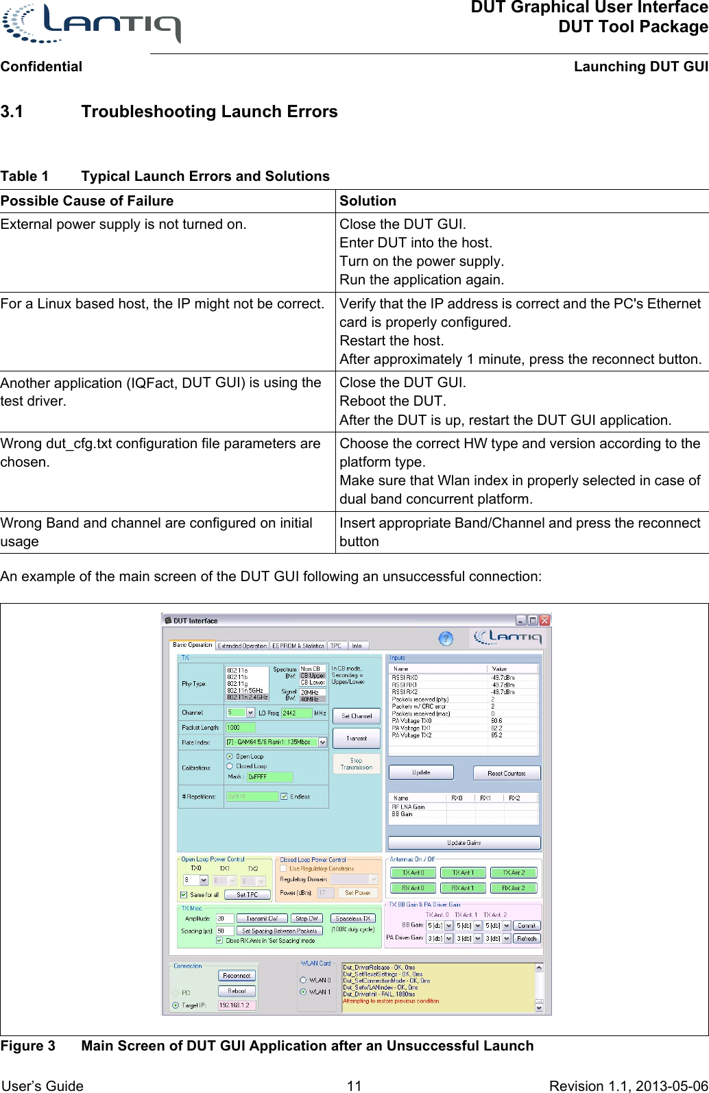
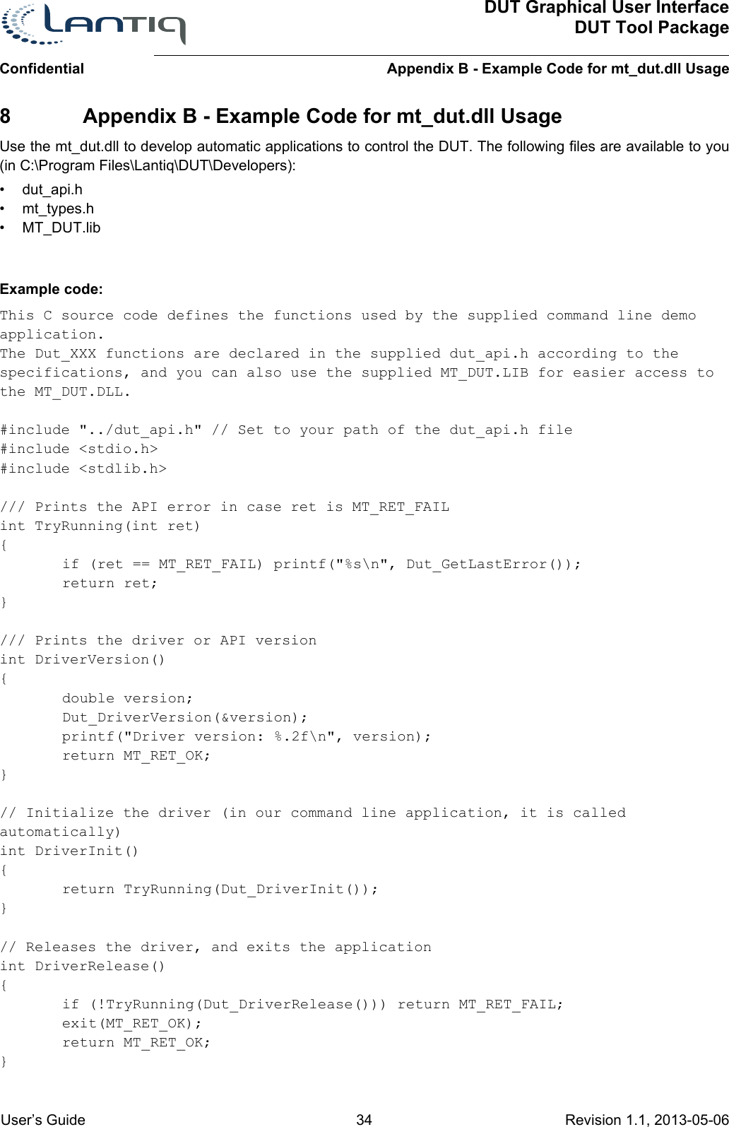
![ConfidentialDUT Graphical User InterfaceDUT Tool PackageUsing the DUT GUI User’s Guide 20 Revision 1.1, 2013-05-06 5.5.2 Hardware LimitationsThe hardware limitation are different for every type of board. During EMI certification, for example, an RF board might need to lower the output power even more than required in the regulation for the specific channel used because of band edge, 2nd harmonic and other limitations.The DUT GUI uses information from the supplied limits.ini file according to the HW Type and HW Version information found in the EEPROM during startup. All known HW types are listed at the top of the ini file.Example:[HWTypes]0x301a_0x8006_0xc4_0x45= GPB-2080x301a_0x0007_0x30_0x43 = GPB-3040x301a_0xC007_0x40_0x44= Easy388 family board (WRX RFIC)If there is no HW limit for the HW used in the specific channel, only the regulatory limits will be taken into account.DUT GUI will not allow users to change the desired Tx power value more than the limitation described above allow.After the desired power is changed, click Set power for the change to take effect.5.6 Changing BB and PA Driver GainsFigure 13 BB and PA Driver Gain SettingThe DUT GUI allows you to control the TPC attenuator in the RF chip and two additional RF chip internal amplifiers:• Base band gain (BB gain) - In the BB side of the RF chip there is an option to boost dB gain by 0, 2.5, or 5• PA driver gain - In the RF side of the RF chip there is an option to gain 0 or 3 dB using the PA driver gain controlThe system automatically determines the initial value of both gains and this might differ between frequencies and bands.Note: This Gain change option is applicable for XWAY™ WAVE300 devices only.5FCC 120 48 17 No5FCC 220 52 24 Yes5FCC 220 56 24 Yes5FCC 220 60 24 Yes5FCC 220 64 24 YesTable 5 Reg Limits (cont’d)Band Domain Class Spacing Channel Power Limit Sm Required](https://usermanual.wiki/Humax/T9.User-Manual/User-Guide-3606265-Page-20.png)
![ConfidentialDUT Graphical User InterfaceDUT Tool PackageAvailable Functions in mt_dut.dll User’s Guide 30 Revision 1.1, 2013-05-06 Figure 23 Burn Calibration Structure6.4 EEPROM Burning New Calibration Method Functionextern MT_RET PASCAL Dut_EEPROM3_Burn_Cal_Data(const Dut_CalDataStruct3* inCalArray, Dut_CalDataStruct3* outCalArray, int numStructures);// Burn calibration data using the Dut_CalDataStruct3 for EEPROM Version 3 (defined // above)// int numStructurs - # of Dut_AntCalDataStruct3 structures in calArray (2.4 + 5 GHz)// outCalArray is an optional parameter (can be NULL). If specified, the function // fills the outCalArray with the linear correlation (LR) results.// You can use the function Dut_EEPROM3_Test_Cal_Data to verify the LR results for// part or all of the structures before burning.extern MT_RET PASCAL Dut_EEPROM3_Test_Cal_Data(const Dut_CalDataStruct3* inCalArray, Dut_CalDataStruct3* outCalArray, int numStructures);// Same as Dut_EEPROM3_Burn_Cal_Data but without burning to the EEPROM.6.5 Sensitivity CheckInt Dut_SetMACAddress(const BYTE* macAddr); // Sets the MAC address for the testing procedure. Does NOT burn to EEPROM. macAddr is a BYTE[6] array. This function can and should be called before the call to Dut_DriverInit(). It sets the Rx filter in the lower Mac for packets only in this MAC address.Int Dut_SetRxAntenna(int rx_antenna_mask);](https://usermanual.wiki/Humax/T9.User-Manual/User-Guide-3606265-Page-30.png)

![ConfidentialDUT Graphical User InterfaceDUT Tool PackageAvailable Functions in mt_dut.dll User’s Guide 32 Revision 1.1, 2013-05-06 Int Dut_ReadRFGain(BYTE* RF_Gain_Values); // Read RF Gain - RF_Gain_Values must be an array of 6 bytes with:0 - RX0_LNA_Gain1 - RX0_MIXER_GAIN_6DB2 - RX1_LNA_Gain3 - RX1_MIXER_GAIN_6DB4 - RX2_LNA_Gain5 - RX2_MIXER_GAIN_6DBInt Dut_ReadBBGain(int* BB_Gain_Values); // Read BB Gain - BB_Gain_Values must be an array of three integers for each antenna - returns total of LPF1+LPF2+VGA in dbInt Dut_ReadDetector(BYTE* detector_values); // Read Detector - detector_values must be an array of four bytes:0 - PLL_Lock1 - THD0 (Threshold detector RX0 output)2 - THD1 (Threshold detector RX1 output)3. - THD2 (Threshold detector RX2 output)"Int Dut_ReadVoltageValueEx(double* pVoltage, int numSamples) // Same as ReadVoltageValue, numSamples - # of samples for each antenna for averaging. Default value for numSamples (used in Dut_ReadVoltageValue) function is 35Tx Gains Set/Get for each TX antenna:Int Dut_SetTxGains(int* bbGains, int* driverGains);Int Dut_GetTxGains(int* bbGains, int* driverGains);// Parameters: // bbGains - array of 2 ints (for each TX ant). Each value can be 0 for 0[db], 1 for 2.5[db] and 2 for 5[db]// driverGains - array of 2 ints (for each TX ant). Each value can be 0 (Low) or 1 (High)Dut_StopRISC() // Stops the GenRISC processor (PHY)Dut_StartRISC() // Starts the GenRISC processor (PHY)](https://usermanual.wiki/Humax/T9.User-Manual/User-Guide-3606265-Page-32.png)
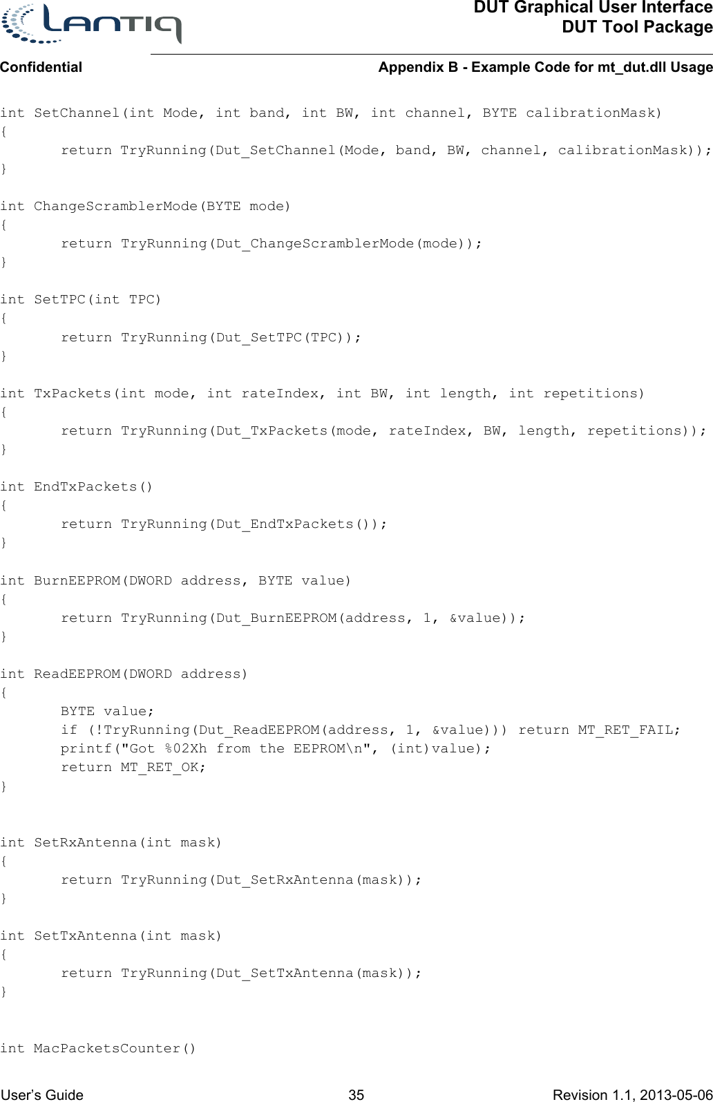
![ConfidentialDUT Graphical User InterfaceDUT Tool PackageAppendix B - Example Code for mt_dut.dll Usage User’s Guide 36 Revision 1.1, 2013-05-06 { DWORD PacketsCounter; if(!TryRunning(Dut_MacPacketsCounter(&PacketsCounter))) return MT_RET_FAIL; printf("MAC PacketCounter = %d\n",(int)PacketsCounter); return MT_RET_OK;}int PhyPacketsCounter(){int i;double PacketsVector[2];if(!TryRunning(Dut_PacketsCounter(PacketsVector))) return MT_RET_FAIL;for (i=0; i<2; ++i)printf("PacketCounter %d=%f\n", i, PacketsVector[i]);return MT_RET_OK;}int ResetPacketsCounter(){if(!TryRunning(Dut_ResetPacketsCounter())) return MT_RET_FAIL;return MT_RET_OK;}int RSSIVector(){int i;double RSSIVector[3];if (!TryRunning(Dut_RSSIVector(RSSIVector))) return MT_RET_FAIL;for (i=0; i<3; ++i)printf("RSSI Ant %d=%f\n", i, RSSIVector[i]);return MT_RET_OK;}// Directly writes a masked 32-bit value to the firmware memory space.int WriteReg(DWORD address, DWORD data, DWORD mask){return TryRunning(Dut_WriteData(address, data, mask));}int ReadReg(DWORD address, DWORD mask){DWORD data = 0;if (!TryRunning(Dut_ReadData(address, &data, mask))) return MT_RET_FAIL;printf("Received data: 0x%08X\n", data);return MT_RET_OK;}int ReadVoltageValue(int antenna){](https://usermanual.wiki/Humax/T9.User-Manual/User-Guide-3606265-Page-36.png)
![DUT Graphical User InterfaceDUT Tool PackageAppendix B - Example Code for mt_dut.dll UsageConfidential User’s Guide 37 Revision 1.1, 2013-05-06 double voltage = 0.0;if (!TryRunning(Dut_ReadVoltageValue(antenna, &voltage))) return MT_RET_FAIL;printf("Antenna voltage: %f\n", voltage);return MT_RET_OK;}int BURN_DATE(int year, int week){return (TryRunning(Dut_Burn_Date(year, week)));}int BURN_MAC_ADDRESS(BYTE b0, BYTE b1, BYTE b2, BYTE b3, BYTE b4, BYTE b5){BYTE macAddr[6] = {b0, b1, b2, b3, b4, b5};return (TryRunning(Dut_Burn_MAC_Address(macAddr)));}int BURN_CAL_DATA(int channel, int band, int TPC0, int maxPower0, double a0, double b0){int i;Dut_CalDataStruct calData;calData.band = band;calData.channel = channel;for (i=0; i<2; ++i) // In this example, we use the same variables for ant0 and ant1{calData.ants[i].TPC = TPC0;calData.ants[i].a = a0;calData.ants[i].b = b0;calData.ants[i].maxPower = maxPower0;}return (TryRunning(Dut_Burn_Cal_Data(&calData)));}// Burn an example file to the EEPROMint BURN_FILE(){return (TryRunning(Dut_Burn_File("eeprom_file.txt")));}// Burns the serial number to the EEPROMint BURN_SN(unsigned int SN){return (TryRunning(Dut_Burn_SN(SN)));}](https://usermanual.wiki/Humax/T9.User-Manual/User-Guide-3606265-Page-37.png)
![DUT Graphical User InterfaceDUT Tool PackageReferencesConfidential User’s Guide 49 Revision 1.1, 2013-05-06 References[1] IEEE 802.11a-1999 High-speed Physical Layer in the 5 GHz bandhttp://standards.ieee.org/getieee802/download/802.11a-1999.pdf[2] IEEE 802.11b-1999 Higher Speed Physical Layer Extension in the 2.4 GHz bandhttp://standards.ieee.org/getieee802/download/802.11b-1999.pdf[3] IEEE 802.11g-2003 Further Higher Data Rate Extension in the 2.4 GHz Bandhttp://standards.ieee.org/getieee802/download/802.11g-2003.pdf[4] IEEE 802.11n-2009—Amendment 5: Enhancements for Higher Throughputhttp://standards.ieee.org/getieee802/download/802.11n-2009.pdf[5] XWAY™ xRX300/WAVE300 DUT Tool Package Release 6.30 Release Note Rev. 2.4](https://usermanual.wiki/Humax/T9.User-Manual/User-Guide-3606265-Page-49.png)