Humminbird 515 525 535 565 Owner S Manual 531368 1_A_English
2014-07-06
: Humminbird Humminbird-515-525-535-565-Owner-S-Manual humminbird-515-525-535-565-owner-s-manual humminbird pdf
Open the PDF directly: View PDF ![]() .
.
Page Count: 26
565
525
515
531368-1_A
Operations Manual
Operations Manual
535

ii
Thank Y
Thank You!
ou!
Thank you for choosing Humminbird®, America's #1 name in fishfinders. Humminbird®
has built its reputation by designing and manufacturing top-quality, thoroughly
reliable marine equipment. Your Humminbird® is designed for trouble-free use in even
the harshest marine environment. In the unlikely event that your Humminbird® does
require repairs, we offer an exclusive Service Policy - free of charge during the first year
after purchase, and available at a reasonable rate after the one-year period. For
complete details, see the separate warranty card included with your unit. We
encourage you to read this operations manual carefully in order to get full benefit from
all the features and applications of your Humminbird® product.
Contact our Customer Resource Center at either 1-334-687-0503 or visit our website
at www.humminbird.com.
WARNING! This device should not be used as a navigational aid to prevent collision,
grounding, boat damage, or personal injury. When the boat is moving, water depth may
change too quickly to allow time for you to react. Always operate the boat at very slow
speeds if you suspect shallow water or submerged objects.
WARNING! Disassembly and repair of this electronic unit should only be performed by
authorized service personnel. Any modification of the serial number or attempt to repair
the original equipment or accessories by unauthorized individuals will void the warranty.
Handling and/or opening this unit may result in exposure to lead, in the form of solder.
WARNING! This product contains lead, a chemical known to the state of California to
cause cancer, birth defects and other reproductive harm.
NOTE: All screens and graphics used in this manual are based on the 320V x 320H display
size of the Fishfinder535; however, this information is applicable to the models which
have 240V x 160H, 240V x 240H and 640V x 320H displays also.
Humminbird®, Selective Fish ID+TM, WhiteLine®, RTS®, X-PressTM Menu, Fish ID+TM, Structure ID®,
TrueArchTM, UltraBlackTM, Angler Profile PresetsTM are trademarked by or registered trademarks of
Techsonic Industries, Inc. © 2004. All rights reserved.
i

iv
Zoom Level (Sonar Zoom View Only) ............................................................................ 20
Sonar Menu Tab 21
Fish ID+.......................................................................................................................... 21
Fish Sensitivity ............................................................................................................ 22
Real Time Sonar (RTS®) Window (Sonar View Only)............................................ 23
Depth Lines (Advanced) ............................................................................................ 24
Surface Clutter (Advanced) ...................................................................................... 25
Noise Filter (Advanced).............................................................................................. 26
Max Depth (Advanced).............................................................................................. 26
Water Type (Advanced).............................................................................................. 27
Alarms Menu Tab 28
Depth Alarm................................................................................................................ 28
Fish ID Alarm .............................................................................................................. 29
Low Battery Alarm...................................................................................................... 30
Alarm Tone .................................................................................................................. 30
Setup Menu Tab 31
Units - Depth................................................................................................................ 32
Units - Temp (International Only) ............................................................................ 32
Units - Distance (with Temp/Speed Only).............................................................. 32
Units - Speed (with Temp/Speed Only) .................................................................. 33
User Mode.................................................................................................................... 33
Language (International Only) ................................................................................ 33
Triplog Reset (with Temp/Speed Only) .................................................................. 34
Restore Defaults.......................................................................................................... 34
Select Views (Advanced) .......................................................................................... 35
Select Readouts (Advanced, Sonar View Only) .................................................... 36
Depth Offset (Advanced) .......................................................................................... 37
Temp Offset (Advanced)............................................................................................ 38
Speed Calibration (Advanced, with Temp/Speed Only) ...................................... 38
T
Table of C
able of Con
ont
ten
ents
ts
iii
How Sonar Works 1
Single Beam Sonar ........................................................................................................ 1
DualBeam Sonar............................................................................................................ 1
What’s On the Screen 2
Views 4
Sonar View .................................................................................................................... 4
Understanding Sonar History .................................................................................... 5
Real Time Sonar (RTS®) Window................................................................................ 5
Sonar Zoom View ........................................................................................................ 6
Big Digits View .............................................................................................................. 7
Bottom Presentation.................................................................................................... 8
Key Functions 10
POWER/LIGHT Key .................................................................................................... 10
VIEW Key .................................................................................................................... 10
MENU Key .................................................................................................................... 10
4-WAY Cursor Control Key .......................................................................................... 11
EXIT Key ........................................................................................................................ 11
Powering Up the Unit 12
The Menu System 12
Start-Up Options Menu 15
Normal Operation ...................................................................................................... 15
Simulator .................................................................................................................... 15
System Status ..............................................................................................................16
Sonar X-Press™ Menu 17
Sensitivity .................................................................................................................... 17
Upper Range (Advanced: Sonar and Big Digits View Only) ................................ 18
Lower Range ................................................................................................................ 18
Chart Speed ................................................................................................................ 19
Bottom View .............................................................................................................. 20
T
Table of C
able of Con
ont
ten
ents
ts
1
How Sonar W
How Sonar Work
orks
s
Sonar technology is based on sound waves. The Humminbird FishFinder uses sonar
to locate and define structure, bottom contour and composition, as well as depth
directly below the transducer.
Your FishFinder sends a sound wave signal and determines distance by measuring
the time between the transmission of the sound wave and when the sound wave is
reflected off of an object; it then uses the reflected signal to interpret location, size,
and composition of an object.
Sonar is very fast. A sound wave can travel from the surface to a depth of 240 ft
(70 m) and back again in less than ¹⁄₄ of a second. It is unlikely that your boat can
"outrun" this sonar signal.
Your FishFinder will either have Single Beam sonar or DualBeam sonar. Find the
correct sonar description that applies to your unit.
NOTE: All sonar units typically read to deeper depths in fresh water than in salt water.
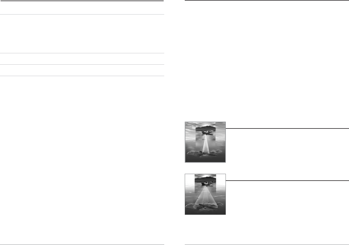
Single Beam Sonar
Single Beam Sonar
Your Humminbird FishFinder 515, 525 or 535 uses a 200 kHz
single beam sonar system with a 20° area of coverage. Depth
capability is affected by such factors as boat speed, wave
action, bottom hardness, water conditions and transducer
installation.
DualBeam Sonar
DualBeam Sonar
Your Humminbird FishFinder 565 uses a 200/83 kHz dual beam
sonar system with a wide (60°) area of coverage. DualBeam
sonar is optimized to show the greatest bottom definition using
a narrow (20°) beam yet can still indicate fish found in the wide
(60°) beam when the Fish ID+TM feature is turned on. DualBeam
is ideal for a wide range of conditions - from shallow to very deep water in both fresh
and salt water. Depth capability is affected by such factors as boat speed, wave action,
bottom hardness, water conditions and transducer installation.
v
Troubleshooting 39
FishFinder Doesn’t Power Up .................................................................................. 39
FishFinder Defaults to Simulator with a Transducer Attached .......................... 39
Display Problems........................................................................................................ 40
Finding the Cause of Noise........................................................................................ 41
Humminbird Fishfinder Accessories 42
Specifications 43
Contact Humminbird 44
NOTE: Entries in this Table of Contents which list (International Only) are only available on
products sold outside of the US and Canada by our authorized International Distributors.
To obtain a list of authorized International Distributors, please visit our website at
www.humminbird.com or contact our Customer Resource Center at 334-687-0503 to
locate the distributor nearest you.
NOTE: Entries in this Table of Contents which list (with Temp/Speed Only) require the
purchase of separate accessories. You can visit our website at www.humminbird.com to
order these accessories online or contact our Customer Resource Center at 1-334-687-0503.
T
Table of C
able of Con
ont
ten
ents
ts
3
2
Wha
What’
t’s On the Scr
s On the Screen
een
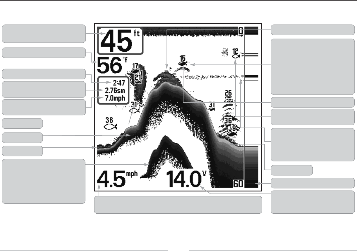
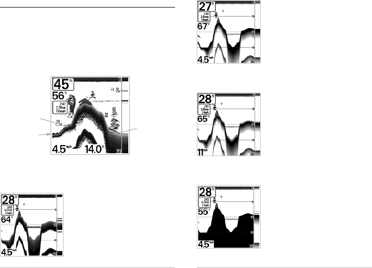
The Humminbird FishFinder can display a variety of useful information about the area under and adjacent to your boat, including the following items:
Depth - water depth; can be set to alarm when the
water becomes too shallow.
Temperature - water surface temperature.
Second Sonar Return - when the sonar signal
bounces between the bottom and the surface of
the water and back again. Use the appearance of
the second return to determine bottom hardness.
Hard bottoms will show a strong second return,
while soft bottoms will show a very weak one or
none at all. Speed - if a Temp/Speed accessory is attached, the FishFinder can display the speed of the boat, and can
keep a Triplog of nautical or statute miles traveled.
Battery Voltage - the voltage of the boat’s battery;
can be set to alarm if the voltage falls below a
certain point.
RTS® (Real Time Sonar) Window
Soft Bottom
Thermoclines - layers of water with different
temperatures that appear at different depths and
different times of the year. A thermocline typically
appears as a continuous band of many gray levels
moving across the display at the same depth.
Structure - where fish may be hiding.
Fish - the FishFinder displays fish as arches and/or
fish icons, and can be set to alarm when a fish of a
certain size is detected. When a target is detected, a
Fish ID+TM symbol appears on the display with the
depth displayed above it. The size of the symbol
indicates the intensity of the sonar return. The unit
will clearly show schools of Bait Fish as "clouds" of
different shapes and sizes, depending on the
number of fish and boat speed.
Bait Ball
Hard Bottom
Rocky Bottom
Timer - Elapsed time with Temp/Speed Accessory.
Distance - Distance traveled with Temp/Speed
Accessory.
Average Speed - Average speed reading with
Temp/Speed Accessory. 83kHz, Wide Beam Hollow Fish Symbol
(Dual Beam Units Only)
200kHz, Narrow Beam Shaded Fish Symbol
5
to show the bottom. Depth Range is automatically selected to keep the bottom visible on
the display, although you can adjust it manually as well (see Sonar
X-PressTM Menu). Either five or six additional Digital Readouts (depending on your model)
display information from optional-purchase accessories. These information boxes can be
customized to show only the information desired (see Setup Menu Tab, Select Readouts).
NOTE: If the Depth number is flashing, it means that the unit is having trouble locating
the bottom. This usually happens if the water is too deep, the transducer is out of the
water, the boat is moving too fast, or for any other reason that the unit can’t accurately
receive continuous data.
Understanding Sonar Hist
Understanding Sonar Histor
ory
y
It is important to understand the significance of the Humminbird display. The
display does NOT show a literal 3-dimensional representation of what is under the
water. Each vertical band of data received by the control head and plotted on the
display represents something that was detected by a sonar return at a particular
time. As both the boat and the targets (fish) may be moving, the returns are only
showing a particular segment of time when objects were detected, not exactly
where those objects are in relation to other objects shown on the display.
R
Real Time Sonar (R
eal Time Sonar (RTS
TS®) Window
) Window
AReal Time Sonar (RTS®) window appears on the right side of the display in the Sonar
View only. The RTS Window always updates at the fastest rate possible for depth
conditions and shows only the returns from the bottom, structure and fish that are within
the transducer beam. The RTS Window plots the depth and intensity of a sonar return.
The Narrow RTS Window
indicates the sonar intensity
through the use of grayscale.
The grayscale used matches
the bottom view grayscale
setting used in the sonar
history window (i.e. Inverse,
StructureID®, WhiteLine®,
Bottom Black). The depth of
the sonar return is indicated
by the vertical placement of
the return on the display
depth scale.
The Wide RTS Window in-
dicates the sonar intensity
through the use of a bar graph.
The length of the plotted return
provides an indication of
whether the return is weak or
strong. The depth of the sonar
return is indicated by the
vertical placement of the return
on the display depth scale. The
Wide RTS Window does not
make use of grayscale. (see
Sonar Menu - RTS®Window).
4
Views
Views
The views available on your FishFinder are:
• Sonar View
• Zoom View
• Big Digits View.
Sonar View is the default view. When the VIEW key is pressed, the display cycles
through the available views. When the EXIT key is pressed, the display cycles
through the available views in reverse order. Any view can be hidden or displayed as
part of the view rotation using Select View from the Advanced Setup Menu.
NOTE: When you change any menu settings that affect the sonar, the view will update
immediately (i.e. you don’t have to exit the menu to apply the change to the screen). For
instance, by switching between "Inverse" and "Structure ID" from the X-PressTM menu it is
possible to quickly alternate between the two viewing methods.
Sonar View
Sonar View
Sonar View presents a historical log of sonar returns. Depth is always displayed.
Readouts for temperature and speed are automatically displayed if the appropriate
accessory is connected. The most recent sonar returns are charted on the right side
of the window; as new information is received, the older information is moved
across the display to the left.
A Digital Depth Readout is displayed in the upper left corner. A scale with Upper and
Lower Depth Range readouts appears along the right edge of the Sonar View. The
scale indicates the distance from the surface of the water to a depth range sufficient
Upper Range
Depth
Temperature
Triplog w/ Temp/Speed
Speed w/ Temp/Speed
Lower Range
RTS Window

7
Big Digits View
Big Digits View
Big Digits View provides digital data in a large, easy-to-see format. Depth is always
displayed. Readouts for temperature, speed and Triplog information are displayed
automatically if the appropriate accessory is connected to the system. The Triplog
shows distance traveled, average speed, and time elapsed since the Triplog was last
reset. The digital readouts in the Big Digits View cannot be customized.
Big Digits View
Speed
Timer shows the time
elapsed since Triplog
was last reset
Distance is the distance
traveled since the Triplog
was last reset
Voltage - the battery
voltage.
Average Speed shows
the speed since the
Triplog was last reset
Digital Depth
Temperature
6
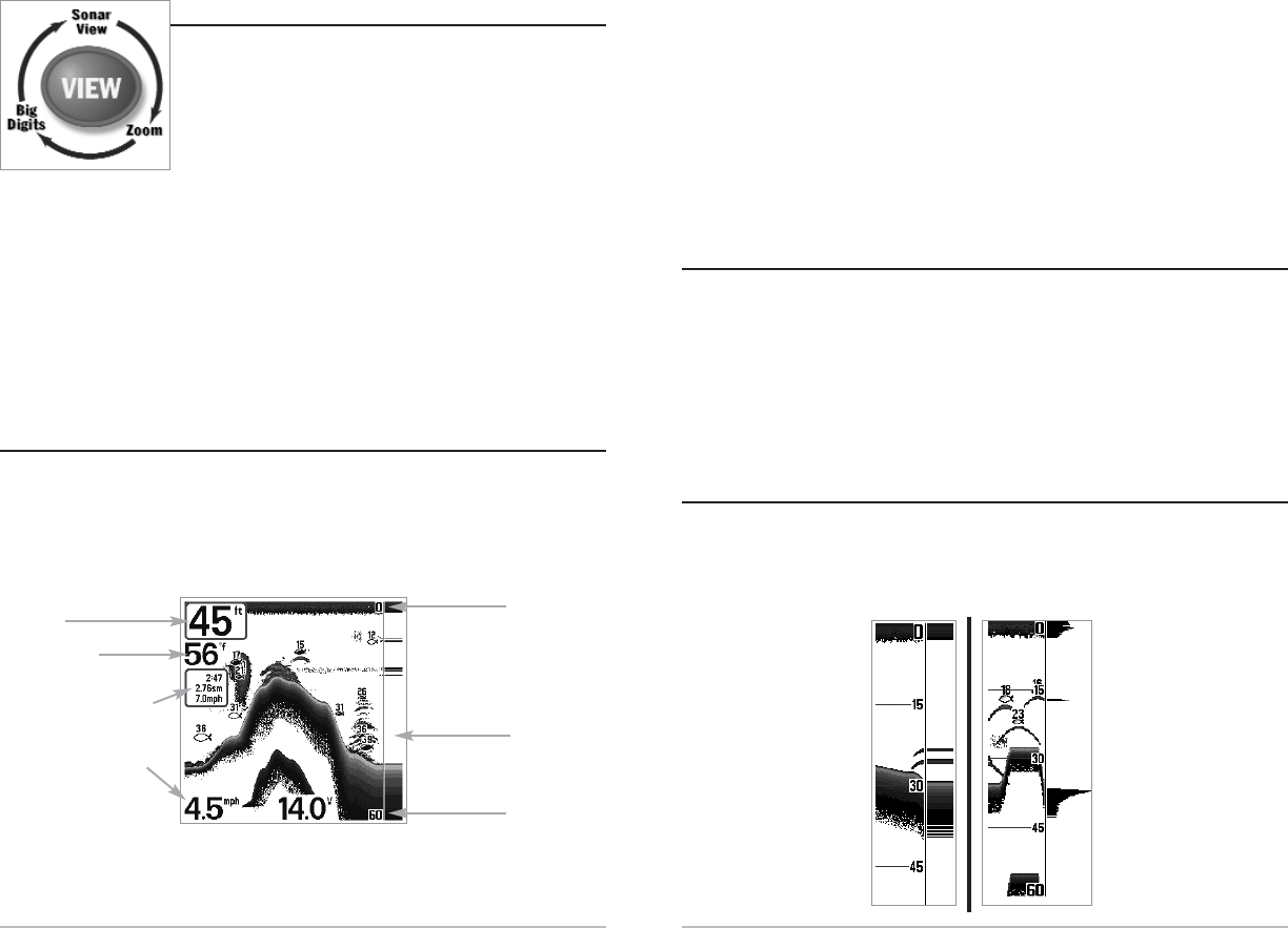
Sonar Z
Sonar Zoom View
oom View
Sonar Zoom View increases the displayed resolution to separate sonar returns that
are very close together, such as those caused by fish suspended close to the bottom
or within structure. In Zoom View, the display is split to show a narrow slice of the
full range view on the right and the zoomed view on the left. The full range view on
the right also contains the Zoom Preview Box that shows what part of the full range
view is shown in zoom view on the left; the Zoom Preview Box tracks the bottom in
the full range view.
As the depth changes, the zoomed view updates automatically to display a
magnified image of the bottom. The Zoom Preview Box shows where the zoomed
view is in relation to the full range view. The Zoom Level, or magnification, is
displayed in the lower left corner and can be changed to suit conditions (see Sonar
X-Press Menu: Zoom Level). Upper and Lower Zoom Depth Range numbers indicate
the depth of the water which is being viewed.
Digital depth is displayed in the upper left hand corner. No additional digital
readouts, such as Temperature or Voltage, can be displayed in the Sonar Zoom View.
Sonar Zoom View
Full Range
View
Zoomed View Zoom
Preview Box
Zoom Level
Lower
Depth Range
9
Structure ID® represents weak returns as light
pixels and strong returns as dark pixels. This has the
benefit of ensuring that strong returns will be
clearly visible on the display.
WhiteLine® highlights the strongest sonar returns
in white resulting in a distinctive outline. This
has the benefit of clearly defining the bottom on
the display.
Bottom Black displays all pixels below the bottom
contour as black, regardless of signal strength.
This has the benefit of providing a high contrast
between the bottom and other sonar returns on
the display. Any targets such as fish, structure
and thermoclines will be shown using the Structure
ID method.
8
Bot
Bott
tom Pr
om Presen
esenta
tation
tion
As the boat moves, the unit charts the changes in depth on the display to create a profile
of the Bottom Contour. The type of bottom can be determined from the return charted
on the display. A Hard Bottom such as compacted sediment or flat rock appears as a
thinner line across the display. A Soft Bottom such as mud or sand appears as a thicker
line across the display. Rocky Bottoms have a broken, random appearance.
The sonar returns from the bottom, structure and fish can be represented as either
Inverse (default), WhiteLine®, Structure ID®, or Bottom Black. See Sonar X-Press
Menu: Bottom View for details on how to set the bottom view.
Inverse is a method where weak returns are shown
with dark pixels and strong returns with lighter
pixels. This has the benefit of ensuring that weak
signals will be clearly visible on the display.
Bottom Contour Profile with
RTS® Window. Temp/Speed
Accessory is optional.
Rocky Bottom
Hard Bottom
Soft Bottom

11
Start-Up Options Menu - Press the MENU key during the power up sequence to view
the Start-Up Options menu.
X-PressTM Menu - Press the MENU key once for the Sonar X-Press Menu. The X-Press
menu allows you to access frequently-used settings without having to navigate
through the whole menu system. When the X-Press menu is displayed, you can use
the UP or DOWN Cursor keys to move to a particular menu choice. As soon as you
alter a parameter (using the RIGHT or LEFT Cursor keys) the X-Press menu will
collapse temporarily, and the screen will update if it is affected by your menu setting
change, allowing you to see the effects of your action immediately. Reactivate the X-
Press Menu by using the UP or DOWN Cursor keys.
Main Menu - Press the MENU key twice for the tabbed Main Menu System. The Main
Menu System is organized under tabbed headings to help you find a specific menu item
quickly: Alarms, Sonar, and Setup tabs are part of your tabbed Main Menu System. Use
the LEFT or RIGHT 4-Way Cursor Control key to select a tab; then use the DOWN or UP
key to select the menu item, and the LEFT or RIGHT key to alter a menu setting.
4
4-W
-Wa
ay C
y Cursor C
ursor Con
ontr
trol K
ol Ke
ey
y
Use the DOWN or UP arrow keys to select a menu choice from the menu
list, then use the LEFT or RIGHT arrow keys to change a menu setting.
NOTE: Menu choices are implemented and saved immediately - no further action is required.
EXIT K
EXIT Ke
ey
y
The EXIT key has multiple functions, depending on the situation:
• If an alarm is sounding, pressing EXIT will cancel the alarm.
• If a menu tab is selected, pressing EXIT will exit the menu mode and return
to the view.
• If a menu is active, pressing EXIT will return to the previous level in the
menu system.
• Pressing EXIT will cycle through the available views in reverse order.
10
K
Ke
ey F
y Func
unctions
tions
Your
Humminbird
user interface consists of a set of easy-to-use keys that work with
various on-screen views and menus to give you flexibility and control over your
fishing experience.
PO
POW
WE
ER/LIGHT K
R/LIGHT Ke
ey
y
The POWER/LIGHT key is used to turn the FishFinder on and off, and
also to adjust the backlight and contrast of the display. Press the
POWER/LIGHT key to turn the unit on. The Title screen is then displayed until the
FishFinder begins sonar operation.
Your FishFinder will start up with the backlight on and will
automatically turn it off to conserve power. To turn the backlight
on for night fishing or to adjust the display constrast press the
POWER/LIGHT key to access the Light and Contrast menu. Use
the DOWN Cursor key to select Light or Contrast and then use the LEFT or RIGHT Cursor
key to change the settings. Press EXIT to exit the Light and Contrast menu.
Press and hold the POWER/LIGHT key for 3 seconds to turn the unit off. A message
will appear telling you how many seconds there are until shutdown occurs. Your
FishFinder should always be turned off using the POWER/LIGHT key. This will
ensure that shutdown occurs properly and any menu settings will be saved.
VI
VIEW K
EW Ke
ey
y
The VIEW key is used to cycle through all available views. Press the
VIEW key to advance to the next view. Repeatedly pressing VIEW
cycles through all views available. Views can be hidden to optimize the system to
your fishing requirements (see Setup Menu Tab: Select Views, Advanced).
M
ME
EN
NU K
U Ke
ey
y
The MENU key is used to access the menu system.
Main Menu Tabs - Less frequently-adjusted menus
are grouped into the Main Menu System. The Main
Menu system is organized under the following tab
headings to help you find a specific menu item
quickly: Alarms, Sonar, and Setup. Press the MENU
key twice for the Main Menu, then use the 4-Way
Cursor LEFT or RIGHT key to select a tab, and use
the DOWN or UP key to select a specific menu item
under that tab, then use the LEFT or RIGHT keys
again to change a menu setting. Press the EXIT key
to move quickly to the top of the tab. A down arrow
at the bottom of a menu means that you can scroll
to additional menu choices using the DOWN Cursor key. A right or left arrow on a
menu choice means that you can use the RIGHT or LEFT Cursor keys to make changes
or see more information.
NOTE: The Main Menu choices will vary depending on whether you are in Normal or Advanced
user mode.
User Mode (Normal or Advanced) - An Advanced Mode is provided for users who
desire the highest level of control over the FishFinder, and Normal Mode for users
who desire greater simplicity and fewer menu choices. Additional Advanced menu
choices will be displayed throughout the menu system when you navigate to
specific menus while in Advanced Mode. Any changes made while in Advanced
Mode will remain in effect after you switch back to Normal Mode. For example, if
you set specific views to be visible while in Advanced User Mode, and then return to
Normal User Mode, those views will still be visible. See Setup Menu Tab: User Mode
for specific instructions on changing to Advanced User Mode.
Main Menu System
Normal User Mode
13
12
P
Pow
owering Up the Unit
ering Up the Unit
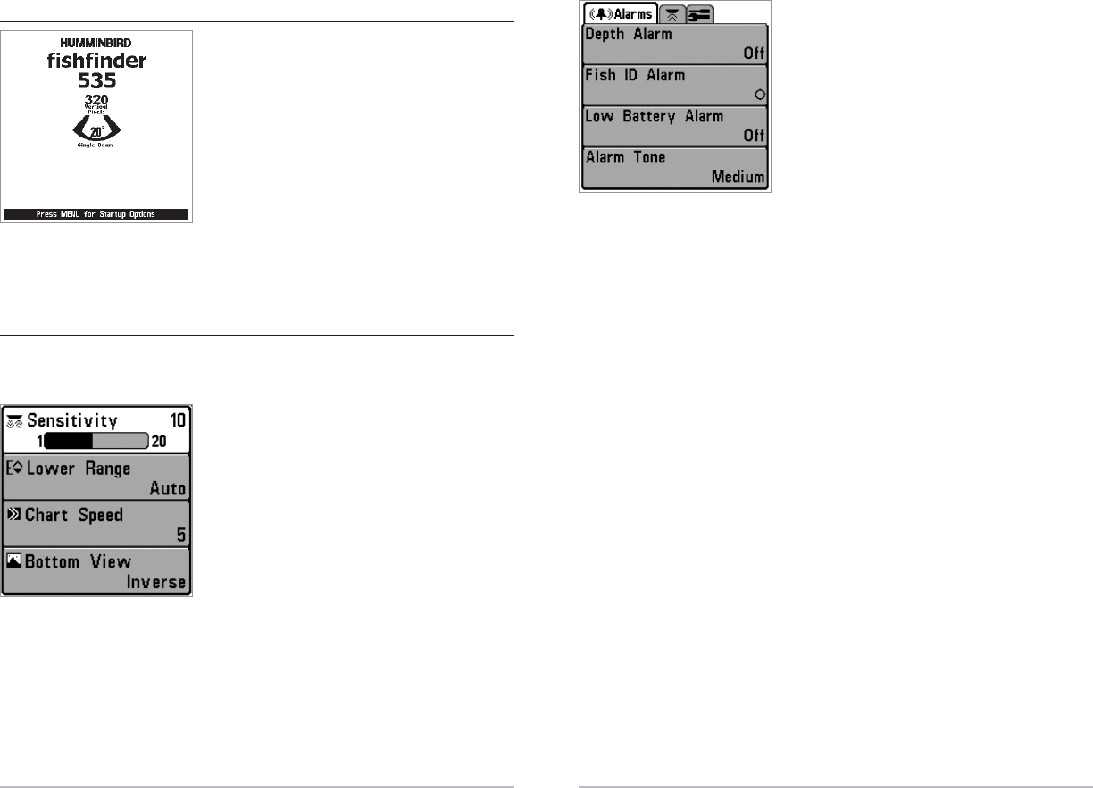
Turn on your FishFinder by pressing the
POWER/LIGHT key. The Title screen is displayed
until the FishFinder begins operation. Your
FishFinder will begin Normal or Simulator operation,
depending on the presence or absence of a
transducer.
The Menu S
The Menu Syst
ystem
em
The menu system is divided into easy-to-use menu modules. The main components
of the menu system are:
Start-Up Options Menu - Press the MENU key
during the power up sequence to view the Start-Up
Options menu.
X-PressTM Menu - The X-Press menu allows you to
access the settings that are changed frequently
without having to navigate through the whole menu
system. Press the MENU key once to display the X-
Press Menu. When you select a menu item from the
X-Press menu, the menu will collapse, leaving only
the menu choice on the screen. Use the Up or Down
Cursor keys to reactivate the X-Press menu.
NOTE: The X-Press Menu choices will vary depending on which view is active when you press the
MENU key, as well as whether you are in Normal or Advanced user mode.
X-PressTM Menu
This is a typical Title screen for the
FishFinder 535. Your model may have a
slightly different Title screen.
S
Star
tart
t-Up Options Menu
-Up Options Menu
Press the MENU key when the Title screen is displayed to access the Start-Up
Options menu.
Use the UP and DOWN 4-Way Cursor keys to
position the cursor, then the RIGHT Cursor key to
select one of the following choices. If you wait too
long, the system will default to whichever menu
mode happens to be highlighted:
• Normal
• Simulator
• System Status.
See the following paragraphs for more information
about each of these choices.
Normal Oper
Normal Opera
ation
tion
Use Normal operation for on the water operation with a transducer connected. In
addition, your FishFinder uses advanced transducer detection methods to
determine if a transducer is connected. If a functioning transducer is connected,
Normal operation will be selected automatically at power up and your FishFinder
can be used on the water.
Exit Normal operation by powering your FishFinder off.
Simula
Simulat
tor
or
Use the Simulator to learn how to use your FishFinder before taking your boat on
the water. The Simulator is a very powerful tool that simulates on the water
operation, providing a randomly-updated display. We recommend going through
this manual while using the Simulator, since all of the menus function and affect the
display the way they actually do when in Normal operating state.
NOTE: To get the full benefit of the Simulator, it is important to select Simulator manually
from the Start-Up Options menu as opposed to letting the FishFinder enter Simulator
automatically (as it will if a transducer is not connected and you do nothing during power
up). Manually selecting Simulator from the Start-Up Options menu allows you to pre-
configure your FishFinder for on the water operation. Any menu changes you make will
be saved for later use.
Start-Up Options Menu
15
14
Total Screen Update - when you change any menu settings that affect the Sonar
View, the view will update immediately (i.e. you don’t have to exit the menu to
apply the change to the screen). For instance, by switching between "Inverse" and
"Structure ID" from the X-Press menu it is possible to alternate quickly between the
two viewing methods.
Sonar Tab, Normal Mode
Sonar Tab, Advanced Mode

17
16
A message will appear on the display periodically
to remind you that you are using the Simulator.
Exit the Simulator by powering your FishFinder off.
S
Syst
ystem S
em Sta
tatus
tus
Use System Status to view system connections
and to conduct a unit self-test.
The following screens are displayed in turn when
you press the VIEW button when using System
Status:
• Self Test
• Accessory Test.
Self Test displays results from the internal diagnostic self test, including unit serial
number, Printed Circuit Board (PCB) serial number, software revision, total hours of
operation and the input voltage.
Accessory Test lists the accessories connected to
the system.
NOTE: The speed accessory will be detected only if the
paddlewheel has moved since your FishFinder was
powered up.
Exit System Status by powering your FishFinder
off.
Accessory Test Screen
System Status Self Test Screen
Simulator
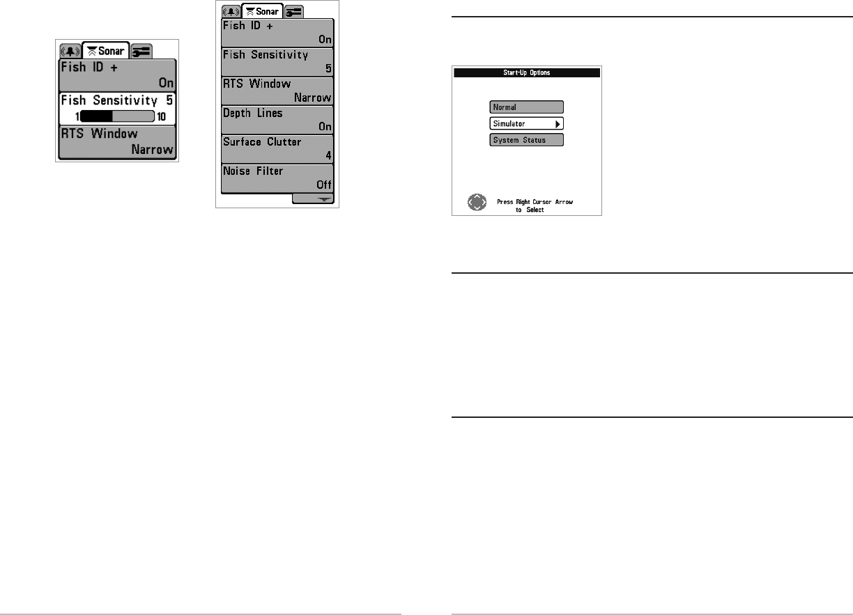
Sonar X
Sonar X-Pr
-Pres
ess
sT
TM
MMenu
Menu
The Sonar X-PressT
TM
Mmenu provides access to the
settings most frequently-used. Press the MENU key
once while in any of the Sonar Views to access the
Sonar X-Pressmenu.
NOTE: Upper Range only appears in Advanced User Mode
when in Sonar or Big Digits View.
NOTE: Zoom Level only appears in Sonar Zoom View.
Sensitivity
Sensitivity
Sensitivity controls how much detail is shown on the
display. Increasing the sensitivity shows more sonar returns from small baitfish and
suspended debris in the water; however, the display may become too cluttered. When
operating in very clear water or greater depths, increased sensitivity shows weaker
returns that may be of interest. Decreasing the sensitivity eliminates the clutter from
the display that is sometimes present in murky or muddy water. If Sensitivity is adjusted
too low, the display may not show many sonar returns that could be fish.
To adjust the Sensitivity:
1. Highlight Sensitivity on the Sonar X-Press menu.
2. Use the LEFT or RIGHT 4-Way Cursor Control keys to increase or decrease the
Sensitivity setting. (Low = 1, High = 20, Default = 10)
Sensitivity at Medium Sensitivity at HighSensitivity at Low
Sonar X-PressTM Menu

19
To adjust the Lower Range:
1. Highlight Lower Range on the Sonar X-PressTM menu.
2. Use the LEFT or RIGHT 4-Way Cursor Control keys to increase or decrease the
Lower Range setting. (AUTO, 10 to 800 feet, 3 to 260 meters [International
Models Only], Default = AUTO)
Char
Chart Speed
t Speed
Chart Speed determines the speed at which the sonar
information moves across the display, and consequently the amount of detail
shown. A faster speed shows more information in the Sonar View and is preferred
by most anglers; however, the sonar information moves across the display quickly.
A slower speed keeps the information on the display longer, but the bottom and
fish details become compressed and may be difficult to interpret. Regardless of the
Chart Speed setting, the RTS® Window will update at the maximum rate possible
for the depth conditions. Adjust Chart Speed to your personal preference.
To adjust the Chart Speed:
1. Highlight Chart Speed on the Sonar X-Press menu.
2. Use the LEFT or RIGHT 4-Way Cursor Control keys to increase or decrease the
Chart Speed setting. (1-9, Ultra, where 1 = Slow, 9 = Fast, Ultra = Fastest,
Default = 4)
18
Upper R
Upper Rang
ange
e
(Adv
(Advanc
anced: Sonar and Big Digits Views Only)
ed: Sonar and Big Digits Views Only)
Upper Range sets the shallowest depth range that will be displayed on the Sonar
and Big Digits Views. The Upper Range menu choice is available when User Mode is
set to Advanced (see Setup Menu Tab: User Mode). Upper Range is often used with
Lower Range.
To adjust the Upper Range:
1. Make sure you are in Advanced Mode, then highlight Upper Range on the
Sonar X-Press menu.
2. Use the LEFT or RIGHT 4-Way Cursor Control keys to increase or decrease the
Upper Range setting. (0 to 790 feet or 0 to 257 meters [International Models
Only], Default = 0)
L
Low
ower R
er Rang
ange
e
Lower Range sets the deepest depth range that will be
displayed. Automatic is the default setting. When in automatic mode, the lower
range will be adjusted by the unit to follow the bottom. Selecting a specific setting
locks the depth range into Manual mode. Use both Upper and Lower Range together
to view a specific depth range manually when looking for fish or bottom structure.
will be displayed in the lower right corner of the screen when you start
manually adjusting the Lower Range to indicate that you are in Manual mode.
For example, if you are fishing in 60 feet of water but are only interested in
the first 30 feet (surface to a depth of 30 feet) you should set the Lower
Depth Range limit to 30. The display will show the 0 to 30 foot range,
allowing you to see a more detailed view than you would see if the display
went all the way to the bottom.
M
For example, if you are only interested in the area between 20 and 50 feet deep,
you should set the Upper Depth Range to 20 and the Lower Depth Range to 50.
The Sonar View will then show the 30 foot area between 20 and 50, and will not
show the surface or the bottom (assuming the bottom is deeper than 50 feet), and
will show greater detail for that area between 20 and 50 feet.
21
Sonar Menu T
Sonar Menu Tab
ab
Press the MENU key twice to access the Main Menu
System and then press the RIGHT Cursor key to select
the Sonar tab.
NOTE: Depth Lines, Surface Clutter, Noise Filter, Max Depth,
and Water Type only appear in Advanced User Mode.
Fish I
Fish ID+
D+T
TM
M
Fish ID+TM uses advanced signal processing to interpret
sonar returns, and will display a Fish Symbol when very selective requirements are met.
When a fish is detected, a fish icon and its depth are displayed above the return that
has been classified as being a fish. Three different fish size icons represent the intensity
of the sonar return, and provide an indicator of relative fish size. Single beam sonar
FishFinders represent targets as Shaded Fish Symbols. Dual beam sonar FishFinders
represent targets detected in the 200 kHz narrow beam as Shaded Fish Symbols, and
represent targets detected in the 83 kHz wide beam as Hollow Fish Symbols with their
associated depths. The sonar return for the Hollow Fish Symbols will not be shown.
200kHz, Narrow Beam Shaded Fish Symbols 83kHz, Wide Beam Hollow Fish
Symbols(Dual Beam Only)
Sonar Menu
20
Bot
Bott
tom View
om View
Bottom View selects the method used to represent
bottom and structure on the display. Inverse represents weak returns as dark pixels and
strong returns as lighter pixels. This has the benefit of ensuring that weak signals will
be clearly visible on the display. Structure ID® represents weak returns as light pixels
and strong returns as dark pixels. This has the benefit of ensuring that strong returns
will be clearly visible on the display. WhiteLine® highlights the strongest sonar returns
in white resulting in a distinctive outline. This has the benefit of clearly defining the
bottom on the display. Bottom Black displays all pixels below the bottom contour as
black, regardless of signal strength. Any targets such as fish, structure and thermoclines
will be shown using the Structure ID method. This has the benefit of providing a high
contrast between the bottom and other sonar returns on the display. (See Bottom
Presentation on page 8 for more detail).
To adjust the Bottom View:
1. Highlight Bottom View on the Sonar X-Press menu.
2. Use the LEFT or RIGHT 4-Way Cursor Control keys to change the Bottom View
setting. (Inverse, Structure ID, WhiteLine, Bottom Black, Default = Inverse)
Z
Zoom L
oom Le
ev
vel
el
(Sonar Z
(Sonar Zoom View Only)
oom View Only)
Zoom Level sets the magnification level for the Sonar Zoom View, and is only available
on the X-PressTM menu when the Sonar Zoom View is active. Use Zoom to increase the
display resolution to separate sonar returns that are very close together.
To adjust the Zoom Level:
1. Highlight Zoom Level on the Sonar X-Press menu.
2. Use the LEFT or RIGHT 4-Way Cursor Control keys to change the Zoom Level
setting for the Sonar Zoom View. (2x, 4x, 6x, 8x, Default = 2x)
NOTE: The Zoom Preview Box tracks the bottom and cannot be moved by the user.
23
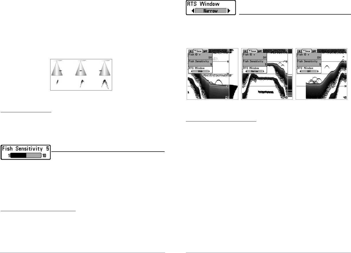
R
Real Time Sonar (R
eal Time Sonar (RTS®) Window
TS®) Window
(Sonar View Only)
(Sonar View Only)
RTS® Window sets the RTS window to either Wide or Narrow, or turns it off in the
Sonar View. The RTS window always updates at the fastest rate possible and only
displays returns that are within the transducer beam. (See Real Time Sonar (RTS)
Window for additional detail).
To change the RTS Window setting:
1. Highlight RTS Window on the Sonar main menu.
2. Use the LEFT or RIGHT 4-Way Cursor Control keys to change the RTS Window
setting. (Wide, Narrow, Off, Default = Off)
RTS Window (Narrow) RTS Window (Off)RTS Window (Wide)
22
When Fish ID+ is turned off, the FishFinder shows only the raw sonar returns on the
display. For dual beam Fishfinders, when Fish ID+ is turned off, only the narrow
beam is used to detect sonar returns. These returns will often result in "arches"
forming on the display, indicating potential targets. Due to the transducer beam
angle, the distance to a fish decreases as the fish moves into the beam, and then
increases as it moves out again, creating a Fish Arch when this distance change is
shown on the display. Boat speed, chart speed, and the position of the fish within
the sonar beam greatly affect the shape of the arch.
To turn Fish ID+ on or off:
1. Highlight Fish ID+ on the Sonar main menu.
2. Use the LEFT or RIGHT 4-Way Cursor Control keys to turn the Fish ID+ setting
On or Off. (On, Off, Default = On)
Fish Sensitivity
Fish Sensitivity
Fish Sensitivity adjusts the threshold of the Fish ID+
detection algorithms. Selecting a higher setting allows weaker returns to be
displayed as fish. This is useful for identifying smaller fish species or baitfish.
Selecting a lower setting displays fewer fish from weak sonar returns. This is
helpful when seeking larger species of fish. Fish Sensitivity is used in conjunction
with Fish ID+. Fish ID+ must be On for Fish Sensitivity to affect the ability of the
FishFinder to identify sonar returns as fish.
To change the Fish Sensitivity setting:
1. Highlight Fish Sensitivity on the Sonar main menu.
2. Use the LEFT or RIGHT 4-Way Cursor Control keys to change the Fish
Sensitivity setting. (Low = 1, High = 10, Default = 5)
Transducer Cone and Fish Arches

25
Sur
Surf
fac
ace Clut
e Clutt
ter
er
(Adv
(Advanc
anced)
ed)
Surface Clutter adjusts the filter that removes surface clutter noise caused by algae
and aeration. The lower the setting, the less surface clutter will be displayed. The
Surface Clutter menu choice is available when User Mode is set to Advanced (see
Setup Menu Tab: User Mode).
To change the Surface Clutter setting:
1. Make sure you are in Advanced User Mode, then highlight Surface Clutter on
the Sonar main menu.
2. Use the LEFT or RIGHT 4-Way Cursor Control keys to change the Surface
Clutter setting. (Low = 1 to High = 10, Default = 5)
Surface Clutter
24
Depth Lines
Depth Lines
(Adv
(Advanc
anced)
ed)
Depth Lines divide the display into four equal sections which are separated by three
horizontal depth lines. The depth of each line is displayed along the depth scale. You
can either turn Depth Lines On or Off. The Depth Lines menu choice is available
when User Mode is set to Advanced (see Setup Menu Tab: User Mode).
To change the Depth Lines setting:
1. Make sure you are in Advanced User Mode, then highlight Depth Lines on
the Sonar main menu.
2. Use the LEFT or RIGHT 4-Way Cursor Control keys to turn the Depth Lines
setting On or Off. (Off, On, Default = Off)
Depth Lines
Surface Clutter

27
W
Wa
at
ter T
er Type
ype
(Adv
(Advanc
anced)
ed)
Water Type configures your unit for operation in fresh or salt water. The Water Type menu
choice is available when User Mode is set to Advanced (see Setup Menu Tab: User Mode).
NOTE: In salt water, what would be considered a large fish might be 2 to 10 times bigger
than a large fish in fresh water (depending on the type of fish you are seeking). The salt
water setting allows for a greater range in fish size adjustment to account for this. Also,
make sure that the Water Type is set accurately, especially in salt water, as this affects the
accuracy of deep water depth readings.
To change the Water Type setting:
1. Make sure you are in Advanced User Mode, then highlight Water Type on
the Sonar main menu.
2. Use the LEFT or RIGHT 4-Way Cursor Control keys to change the Water Type
setting. (Fresh, Salt, Default = Fresh)
26
Noise Filt
Noise Filter
er
(Adv
(Advanc
anced)
ed)
Noise Filter adjusts the sonar Noise Filter to limit interference on the display from
sources such as your boat engine, turbulence, or other sonar devices. The Noise
Filter menu choice is available when User Mode is set to Advanced (see Setup Menu
Tab: User Mode).
NOTE: The Off setting removes all filtering; Low, Medium and High settings add
progressive filtering of the sonar returns. In some deep water situations, the High setting
may actually hinder your FishFinder’s ability to find the bottom.
To change the Noise Filter setting:
1. Make sure you are in Advanced User Mode, then highlight Noise Filter on
the Sonar main menu.
2. Use the LEFT or RIGHT 4-Way Cursor Control keys to change the Noise Filter
setting. (Off, Low, Medium, High, Default = Low)
Max Depth
Max Depth
(Adv
(Advanc
anced)
ed)
Max Depth adjusts the maximum depth of operation. The performance of your
FishFinder can be tuned to the maximum depth you will be fishing in by setting the
Max Depth. When a maximum depth is set, your FishFinder will not attempt to
acquire sonar data below that depth, thus increasing overall performance. When Max
Depth is set to Auto, the FishFinder will acquire bottom readings as needed (within
the capacity of the unit). If the bottom is deeper than the Max Depth setting, the
digital depth readout will flash, indicating that the FishFinder cannot locate the
bottom. The Max Depth menu choice is available when User Mode is set to Advanced
(see Setup Menu Tab: User Mode).
To change the Max Depth setting:
1. Make sure you are in Advanced User Mode, then highlight Max Depth on
the Sonar main menu.
2. Use the LEFT or RIGHT 4-Way Cursor Control keys to change the Max Depth
setting. (AUTO, 10 to 800 feet or 3 to 260 meters [International Models
Only], Default = AUTO)
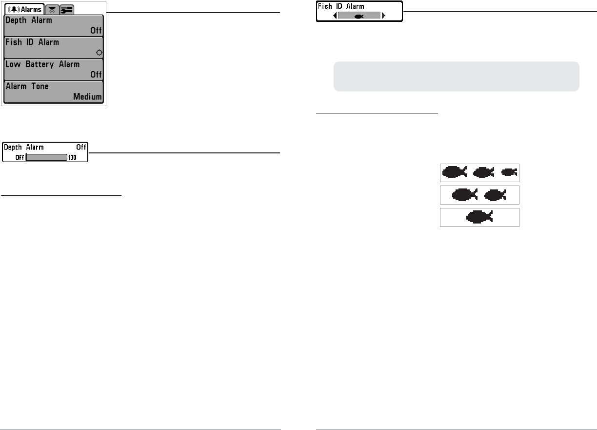
29
Fish I
Fish ID Alarm
D Alarm
Fish ID Alarm sounds when the FishFinder detects fish
that correspond to the alarm setting. Fish ID Alarm will
only sound if Fish ID+TM is on.
To change the Fish ID Alarm setting:
1. Highlight Fish ID Alarm on the Alarms main menu.
2. Use the LEFT or RIGHT 4-Way Cursor Control keys to change the Fish ID Alarm
setting. (Off, All, Large/Medium, Large, Default = Off)
All
Large/Medium
Large
For example, if you've set the Fish ID Alarm to sound for Large fish only, the
Fish ID alarm will sound when a large-sized fish is detected.
28
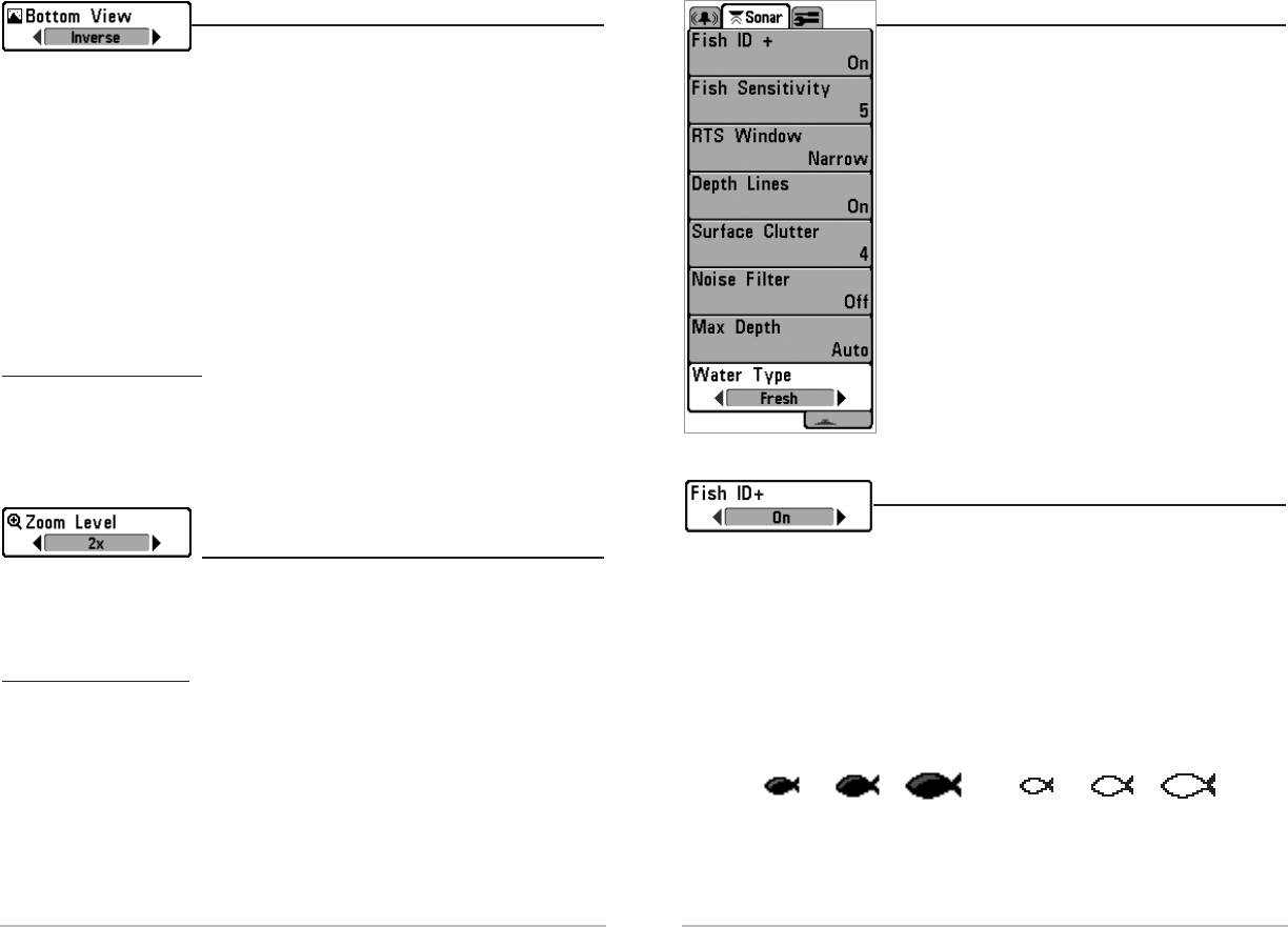
Alarms Menu T
Alarms Menu Tab
ab
From any view, press the MENU key twice to
access the Main Menu System. The Alarms tab will
be the default selection.
NOTE: When an alarm is triggered, you can silence it
by pressing any key. The alarm will be silenced, and
will not be triggered again until you enter a new
instance of the alarm condition.
Depth Alarm
Depth Alarm
Depth Alarm sounds when the depth becomes equal to or
less than the menu setting.
To change the Depth Alarm setting:
1. Highlight Depth Alarm on the Alarms main menu.
2. Use the LEFT or RIGHT 4-Way Cursor Control keys to change the Depth Alarm
setting. (OFF, 1 to 100 feet, or 5 to 30 meters [International Models Only],
Default = OFF)
Alarms Menu
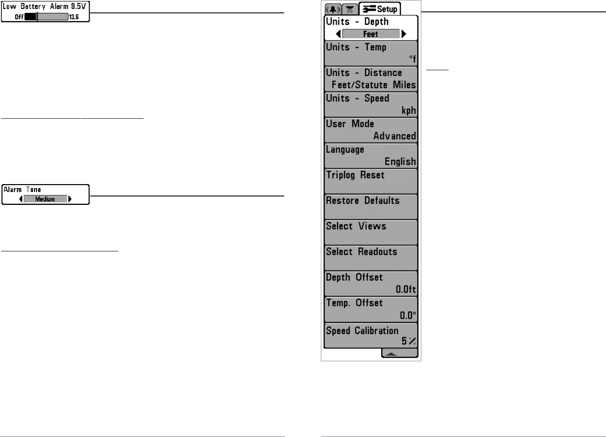
Setup Menu T
Setup Menu Tab
ab
From any view, press the MENU key twice to access
the tabbed Menu System, then press the RIGHT
cursor key until the Setup tab is selected.
NOTE:
Units - Temp (International Models Only)
Units - Distance (Only if Temp/Speed is Connected)
Units - Speed (Only if Temp/Speed is Connected)
Triplog Reset (Only if Temp/Speed is Connected)
Language (International Models Only)
Select Views (Advanced)
Select Readouts (Advanced)
Depth Offset (Advanced)
Temp Offset (Advanced)
Speed Calibration (Advanced, Only
if Temp/Speed Connected)
Setup Menu Tab
30
L
Low Ba
ow Bat
tt
ter
ery Alarm
y Alarm
Low Battery Alarm sounds when the input battery
voltage is equal to or less than the menu setting. The battery alarm will only sound for
the battery which is connected to the fishfinder. The Low Battery Alarm should be set
to warn you when the battery voltage drops below the safety margin that you have
determined. For instance, if you are running a trolling motor (battery operated), you
would want to set the Low Battery Alarm to sound before the battery voltage drops too
low for it to be used to start your main, gasoline-powered engine.
To change the Low Battery Alarm setting:
1. Highlight Low Battery Alarm on the Alarms main menu.
2. Use the LEFT or RIGHT 4-Way Cursor Control keys to change the Low Battery
Alarm setting. (Off, 8.5V - 13.5V, Default = Off)
Alarm T
Alarm Tone
one
Alarm Tone selects the pitch of the alarm sound. A
brief tone will be produced as you adjust the Alarm Tone so that you can select
the tone that you can hear best.
To change the Alarm Tone setting:
1. Highlight Alarm Tone on the Alarms main menu.
2. Use the LEFT or RIGHT 4-Way Cursor Control keys to change the Alarm Tone
setting. (High, Medium, Low, Default = Medium)
31
33
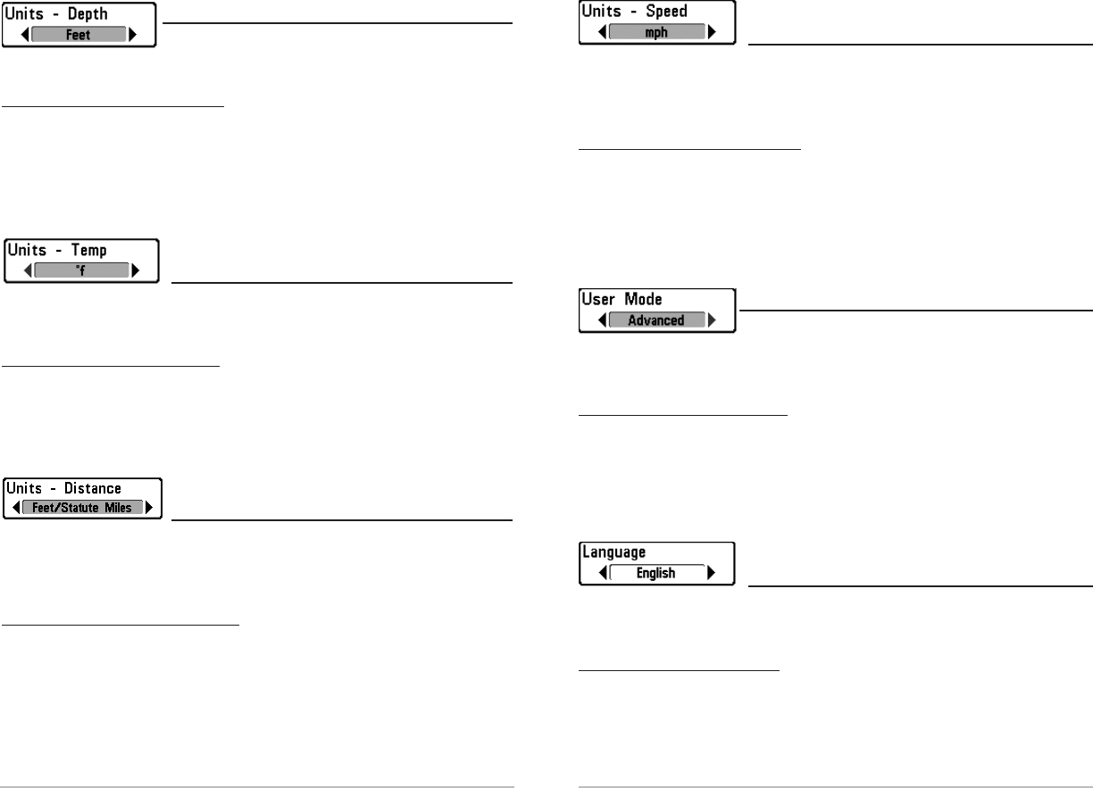
Units - Speed
Units - Speed
(with T
(with Temp/
emp/Speed Only)
Speed Only)
Units - Speed selects the units of measure for speed-related readouts, and will only
appear in the menu if a Temp/Speed Accessory is connected and the paddlewheel
has moved at least once.
To change the Units - Speed setting:
1. Highlight Units - Speed on the Setup menu.
2. Use the LEFT or RIGHT 4-Way Cursor Control keys to change the Units - Speed
setting. (kph [International Models Only], mph, kts, Default = kph for
International models and mph for Domestic models)
User Mode
User Mode
User Mode sets the menu system to either Normal or
Advanced. When set to Normal (default setting,) only the basic menu options are
shown. When set to Advanced, additional menu choices are available.
To change the User Mode setting:
1. Highlight User Mode on the Setup menu.
2. Use the LEFT or RIGHT 4-Way Cursor Control keys to change the User Mode setting.
(Normal, Advanced, Default = Normal)
Languag
Language
e
(In
(Int
terna
ernational Only)
tional Only)
Language selects the display language for menus.
International Models Only.
To change the Language setting:
1. Highlight Language on the Setup menu.
2. Use the LEFT or RIGHT 4-Way Cursor Control keys to change the Language
setting. (Default = English)
32
Units - Depth
Units - Depth
Units - Depth selects the units of measure for all depth-
related readouts.
To change the Units - Depth setting:
1. Highlight Units - Depth on the Setup menu.
2. Use the LEFT or RIGHT 4-Way Cursor Control keys to change the Units -
Depth setting. (Meters [International Models Only], Feet, Fathoms; Default
is Meters for International models, and Feet for Domestic models)
Units - T
Units - Temp
emp
(In
(Int
terna
ernational
tional Only)
Only)
Units - Temp selects the units of measure for all temperature-related readouts.
International Models Only.
To change the Units - Temp setting:
1. Highlight Units - Temp on the Setup menu.
2. Use the LEFT or RIGHT 4-Way Cursor Control keys to change the Units - Temp
setting. (Celsius, Fahrenheit; Default = Celsius)
Units - Distanc
Units - Distance
e
(with T
(with Temp/
emp/Speed Only)
Speed Only)
Units - Distance selects the units of measure for all distance-related readouts, and
will only appear in the menu if a Temp/Speed Accessory is connected and the
paddlewheel has moved at least once.
To change the Units - Distance setting:
1. Highlight Units - Distance on the Setup menu.
2. Use the LEFT or RIGHT 4-Way Cursor Control keys to change the Units - Distance
setting. (Domestic Models: Statute Miles, Nautical Miles; Default = Statute Miles;
International Models: Meters/Kilometers, Meters/Nautical Miles, Feet/Statute
Miles, Feet/Nautical Miles; Default = Meters/Kilometers)
35
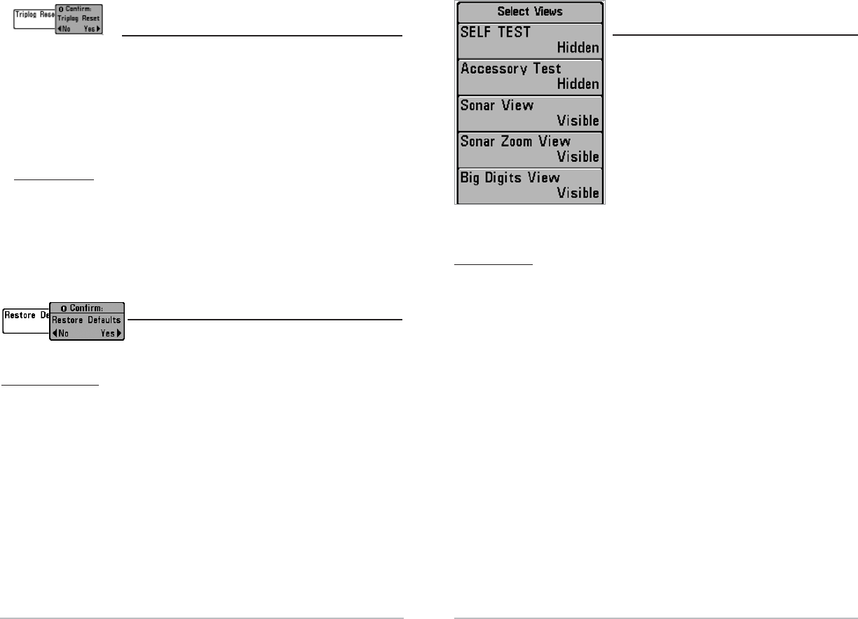
Selec
Select Views
t Views
(Adv
(Advanc
anced)
ed)
Select Views sets the available views to either
hidden or visible in the view rotation. The view
will be removed from the view rotation if it is set to
Hidden and will be displayed in the view rotation if
it is set to Visible. The following views are
available: Self Test, Accessory Test, Sonar View,
Sonar Zoom View, Big Digits View, and their
display status can be changed only when in
Advanced User Mode (see Setup Menu Tab: User
Mode.)
To Select Views:
1. Make sure you are in Advanced User Mode, then highlight Select Views on
the Setup menu.
2. Use the RIGHT 4-Way Cursor Control key to initiate this procedure.
3. The Select Views submenu will appear, showing a list of all Views that can
be hidden or made visible. Use the UP or DOWN Cursor keys to select a
particular view, then use the RIGHT or LEFT Cursor keys to change the View
status from Visible to Hidden or vice versa.
Select Views
34
T
Triplog R
riplog Reset
eset
(with T
(with Temp/
emp/Speed Only)
Speed Only)
Triplog Reset resets the Triplog to zero, and will only appear in the menu if a
Temp/Speed Accessory is connected and the paddlewheel has moved at least once.
The Triplog provides the following information: timer for elapsed time, distance
traveled since last reset, and average speed.
Note: See Setup Menu Tab: Select Readouts (Advanced) to find out how to display Triplog
information on the screen.
To Reset Triplog:
1. Highlight Reset Triplog on the Setup menu.
2. Use the RIGHT 4-Way Cursor Control key to initiate Triplog Reset.
3. The Confirm dialog box will appear. To reset the Triplog, press the RIGHT
Cursor key once more. To cancel Reset Triplog, press the LEFT Cursor key.
R
Rest
estor
ore Def
e Defaults
aults
Restore Defaults resets ALL menu settings to their
factory defaults. Use this menu choice with caution!
To Restore Defaults:
1. Highlight Restore Defaults on the Setup menu.
2. Use the RIGHT 4-Way Cursor Control key to initiate restoring defaults.
3. The Confirm dialog box will appear. To reset the defaults, press the RIGHT
Cursor key once more. To cancel Restore Defaults, press the LEFT Cursor key.
37
To Select Readouts:
1. Make sure you are in Advanced User Mode, then highlight Select Readouts
on the Setup main menu.
2. Use the RIGHT 4-Way Cursor Control key to initiate this procedure.
3. The Select Readouts submenu will appear, showing a list of all Readouts.
Use the UP or DOWN Cursor keys to select a particular Readout position,
then use the RIGHT or LEFT Cursor keys to change what will be displayed at
that position. (Off, Speed, Temperature, Triplog, Voltage)
Depth O
Depth Of
ffset
fset
(Adv
(Advanc
anced)
ed)
Depth Offset will adjust the digital depth readout to indicate depth from the waterline
or boat's keel. Enter a positive vertical measurement from the transducer to the
waterline to read the depth from the waterline. Enter a negative vertical measurement
from the transducer to keel to read the depth from the keel. This menu choice is
available only when in Advanced User Mode (see Setup Menu Tab: User Mode.)
To change the Depth Offset setting:
1. Make sure you are in Advanced User Mode, then highlight Depth Offset on
the Setup menu.
2. Use the LEFT or RIGHT 4-Way Cursor Control keys to change the Depth Offset
setting. (-10.0 to +10.0 or -3 to 3 meters [International Models Only], Default = 0)
36
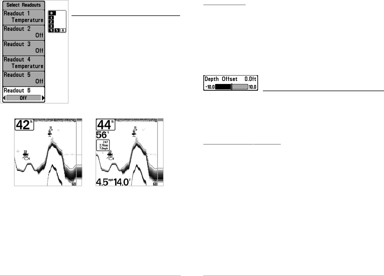
Selec
Select R
t Readouts
eadouts
(Adv
(Advanc
anced, Sonar View Only)
ed, Sonar View Only)
Select Readouts sets individual digital readouts on
the Sonar View. This Advanced feature allows you
to select what data will be displayed in each of
either 5 or 6 (depending on your model) fixed-
position data windows arranged around the left
and bottom edges of the Sonar View screen, or
whether a particular window will be turned off,
displaying nothing in that area; you can access
this menu choice only when in Advanced User
Mode (see Setup Menu Tab: User Mode.)
Data windows can display readouts from supported accessories such as Temp/Speed.
Each data window can either be empty or contain one of the following:
- Speed (will only be displayed if a Temp/Speed Accessory is attached and the
paddlewheel has moved at least once)
- Temperature
- Triplog (will only be displayed if a Temp/Speed Accessory is attached and
the paddlewheel has moved at least once)
- Voltage.
Default Sonar View Customized Sonar View
Select Readouts

39
T
Tr
roubleshooting
oubleshooting
Before contacting the Humminbird Customer Resource Center, please read the
following section. Taking the time to review these troubleshooting guidelines may
allow you to solve a performance problem yourself, and therefore avoid sending
your unit back for repair.
FishFinder Doesn’t Power Up
If your FishFinder doesn’t power up, use the Installation Guide that also comes with
it for specific confirmation details, making sure that:
• the power cable is properly connected to the FishFinder control head,
• the power cable is wired correctly, with red to positive battery terminal and
black to negative terminal or ground
• the fuse is operational
• the battery voltage of the power connector is at least 10 Volts.
Correct any known problems, including removing corrosion from the battery
terminals or wiring, or actually replacing the battery if necessary.
FishFinder Defaults to Simulator with a Transducer Attached
A connected and functioning transducer will cause the newly-started FishFinder to
go into Normal operating mode automatically. If, when you power up the FishFinder,
it goes into Simulator mode automatically, even though a transducer is already
connected, this means that the control head is not detecting the transducer.
Perform the following troubleshooting tasks:
• Using the Installation Guide that also comes with your FishFinder, check to
make sure that the transducer cable is securely connected to the FishFinder.
Reconnect if necessary, and power up the FishFinder again to see if this fixes
the problem.
• Replace the transducer with a known good transducer if available and
power up the control head again.
• Check the transducer cable. Replace the transducer if the cable is damaged
or corroded.
38
T
Temp O
emp Of
ffset
fset
(Adv
(Advanc
anced)
ed)
Temp Offset will adjust the temperature readout by the amount entered. This menu
choice is available only when in Advanced User Mode (see Setup Menu Tab: User Mode.)
To change the Temp Offset setting:
1. Make sure you are in Advanced User Mode, then highlight Temp Offset on
the Setup menu.
2. Use the LEFT or RIGHT 4-Way Cursor Control keys to change the Temp Offset
setting. (-10.0 to +10.0 , Default = 0)
Speed C
Speed Calibr
alibra
ation
tion
(Adv
(Advanc
anced, with T
ed, with Temp/
emp/Speed Only)
Speed Only)
Speed Calibration will adjust the speed readout by the percentage entered, and will
only appear in the menu if a Temp/Speed Accessory is connected and the
paddlewheel has moved at least once when the unit is in Advanced User Mode
(see Setup Menu Tab: User Mode.)
To change the Speed Calibration setting:
1. Make sure you are in Advanced User Mode, then highlight Speed
Calibration on the Setup menu.
2. Use the LEFT or RIGHT 4-Way Cursor Control keys to change the Speed
Calibration setting. (-20% to +20%, Default = 0%)

41
40
Displa
Display Pr
y Problems
oblems
There are several main conditions or sources of possible interference that may
cause problems with the quality of the information displayed on the control head.
Look in the following table for some symptoms of display problems and possible
solutions:
Problem Possible Cause
The control head loses power at
high speeds.
When the boat moves at higher
speeds, the bottom disappears
or suddenly weakens, or the
display contains gaps.
There are no fish detected,
even when you know they are
in the water under the boat,
or sonar readings seem weak
or faulty.
If the power output of your boat’s engine is
unregulated, the control head may be protecting
itself using its over-voltage protection feature. Make
sure the input voltage does not exceed 20 Volts.
The transducer position may need to be adjusted. A
mix of air and water flowing around the transducer
(cavitation) may be interfering with the inter-
pretation of sonar data. See your Installation Guide
for suggestions on adjusting the transducer position.
Electrical noise from the boat’s engine may be
interfering with sonar reception. See Finding the
Cause of Noise for more information.
Sonar readings may be affected if the transducer is
not positioned correctly (i.e. mounted at an angle, not
straight down), or there is some kind of mechanical
interference, either because it is mounted inside a
hull that is too thick for proper sonar transmission,
the bond between the transducer and the hull is not
airtight, or because the transducer is dirty. Check with
your Installation Guide for guidance on re-positioning
the transducer, and make sure the transducer is clean.
Low battery voltage may be affecting the power of
signal transmission.
Electrical noise from the boat’s engine may be
interfering with sonar reception. See Finding the
Cause of Noise for more information.
Finding the C
Finding the Cause of Noise
ause of Noise
Electrical noise usually affects the display with many black dots at high speeds, and
high sensitivity readings. One or more of the following sources can cause noise or
interference:
Possible Source of Noise How to Isolate It
Other electronic devices
The boat’s engine
Cavitation from the boat’s
propeller
Turn off any nearby electronic devices to see if the
problem goes away, then turn them on one at a
time to see if the noise re-appears.
To determine whether the boat’s engine is the
source of the noise, increase the RPMs while the
boat is in neutral and stationary to see if the noise
increases proportionately; if noise appears when
you rev the engine, the problem could be the spark
plugs, alternator, or tachometer wiring. Replace the
spark plugs with resistor plugs, install an alternator
filter, or route the control head power and
transducer cables away from the engine wiring.
Turbulence created by the propeller can cause
noise; make sure the transducer is mounted at
least 15” (38 cm) from the propeller, and that the
water flows smoothly over the face of the
transducer at all times.

43
42
Humminbird Fishfinder Ac
Humminbird Fishfinder Acc
ces
essories
sories
Accessories customize the Humminbird to your needs and enable you to stay on the
edge of new technology and to catch more fish. When an accessory is connected to
the system, additional menus and readouts are added automatically to your
Humminbird menu system. Accessories available today that are supported by your
Humminbird include:
Temperature/Speed: simply plugs into the Humminbird control head and provides
real time speed and temperature readouts, as well as a valuable Triplog function.
NOTE: If an external Temperature/Speed (TS-W) or Temperature (TG-W) accessory is
connected AND a transducer with temperature built in is connected at the same time, the
TS-W or TG-W accessory will override the temperature built in to the transducer.
Be sure to check out our website www.humminbird.com for additional new and
exciting accessories to grow your Humminbird Fishfinder!
NOTE: Accessories require a separate purchase.
Specifica
Specifications
tions
Depth Capability........................................................................ 800 ft (250 m)
Power Output ........................................................................ 250 Watts (RMS)
2000 Watts (Peak to Peak)
Operating Frequency...................... 200 kHz Single Beam (515, 525 and 535)
200 kHz and 83 kHz Dual Beam (565 Only)
Area of Coverage.......................................................... 60° @ -10 dB in 83 kHz
20° @ -10 dB in 200 kHz
Target Separation .......................................................... 2¹₂ Inches (63.5 mm)
Power Requirement.......................................................................... 10-20 VDC
LCD Matrix.......................................................................... 240 V x 160 H (515)
240 V x 240 H (525)
320 V x 320 H (535)
640 V x 320 H (565)
Transducer........................................................................................ XHS-9-20-T
Transducer Cable Length ................................................................ 20 ft (6 m)
Product specifications and features are subject to change without notice.

44
Contact Humminbird
Contact the Humminbird Customer Resource Center
in any of the following ways:
By Telephone
(Monday - Friday 8:00 a.m. to 4:30 p.m. Central Standard Time):
334-687-0503
By e-mail
(typically we respond to your e-mail within three business days):
custserv@techsonic.com
For direct shipping, our address is:
Techsonic Industries, Inc.
Service Department
678 Humminbird Lane
Eufaula, AL 36027 USA
