Humotion DX3520FQ Data Logger User Manual User man
Humotion GmbH Data Logger User man
UserManual.wiki
>
Humotion
>
DX3520FQ User Manual
User man
Navigation menu
Upload a User Manual
Namespaces
Wiki Guide
HTML
PDF
Info
Views
User Manual
Discussion / Help
Navigation


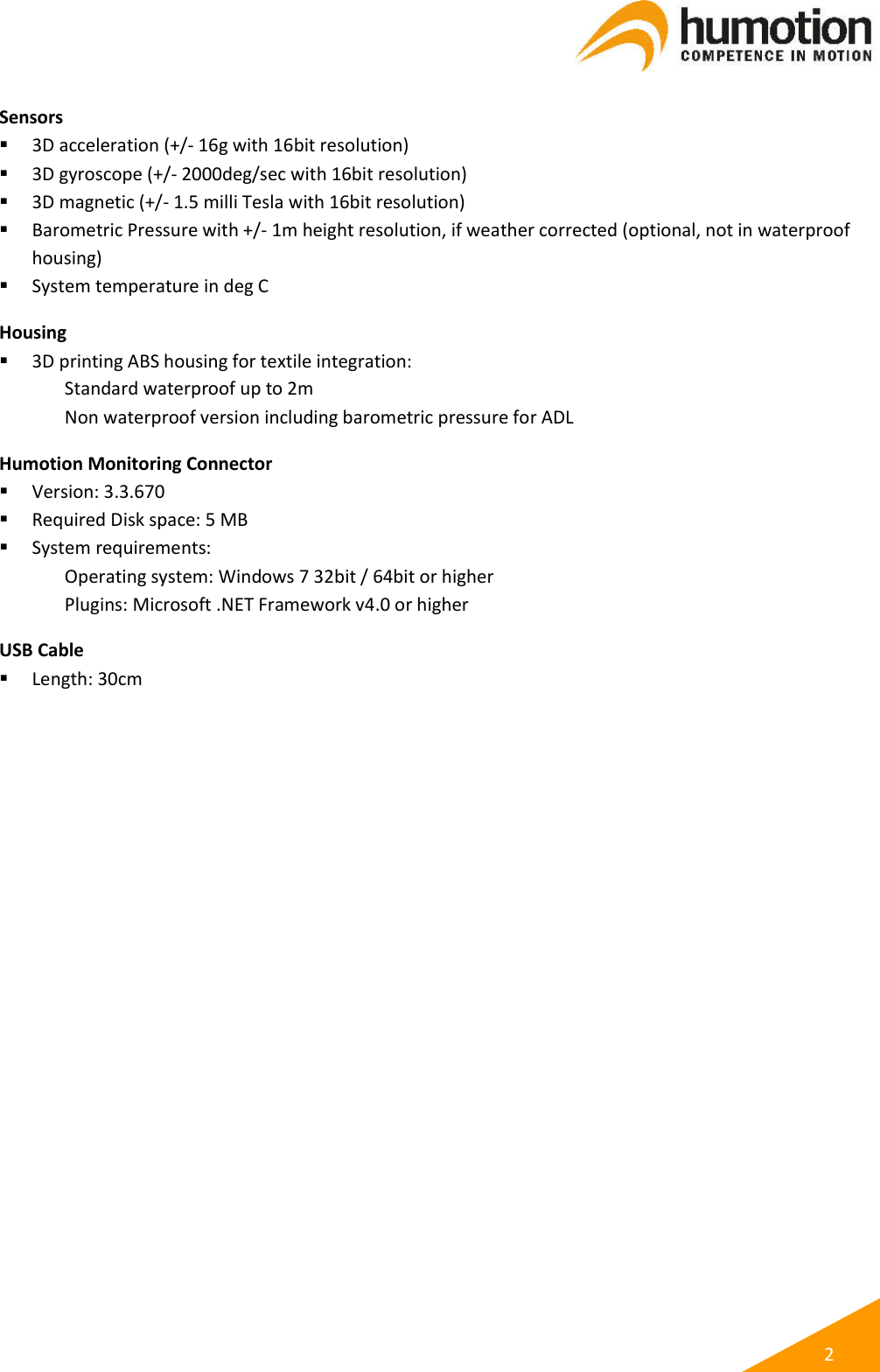
![1 2. DX3.5-20FQ General Information and Specifications The DX3.5-20FQ is a movement monitoring device about the size of a Flash drive. It is capable of recording a vast range of data. The recorded data can be easily exported into a useable format for independent analysis. Control of and interaction with the DX3.5-20FQ (data recording, data transfer, battery charging) is enabled through usage of the Monitoring Connector software. Dimensions [LxWxH mm] Size: 60x20x10mm Weight: < 15g Battery Lithium-Polymer Battery Capacity [mAh] 240 Charging [via USB standard (< 500mA)] full charge < 4hrs 80% charge from empty < 2hrs Measurement Time > 15 hrs @125Hz Sample Rate > 10 hrs @250Hz Sample Rate Memory Storage 512Mbyte > 200 hrs @125Hz Sample Rate (lossless compressed) > 100 hrs @250Hz Sample Rate (lossless compressed) Measurement stops on charging, continues after charging. Storage Format Proprietary lossless compression format (DCM) Allows bit accurate unpack. Export to standard CSV formats possible for scientific applications. Data Rates: 2.5Mbyte / hrs. @125Hz (lossless compressed) 5.0Mbyte / hrs. @250Hz (lossless compressed) External Connections USB (for data transfer and charging)](https://usermanual.wiki/Humotion/DX3520FQ/User-Guide-3826174-Page-4.png)
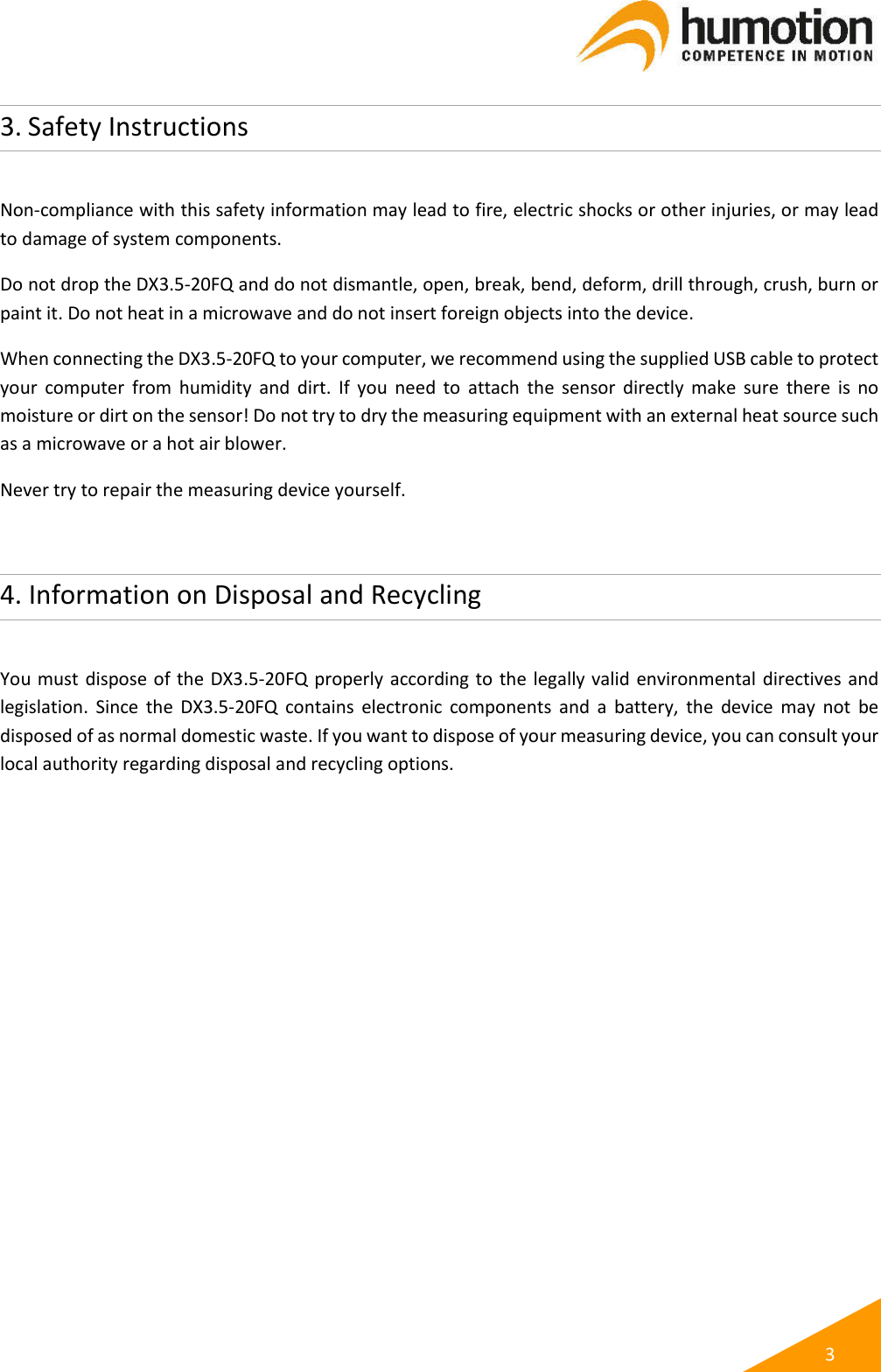
![5 6.2 Data Transfer Each time a measurement is stopped by connecting the Humotion DX3.5-20FQ with your computer’s USB port recorded data is transferred automatically to your computer. Progress of current data transfer is shown in tab “Files to upload” in the Humotion Monitoring Connector software. Once the data transfer is completed, recorded data can be accessed in directory Users\[User Name]\Documents\Humotion Monitoring Connector\Data on our computer. NOTE: Do not unplug the USB cable from the Humotion DX3.5-20FQ USB port before data has been transferred completely. Unplugging during an active data transfer may lead to permanent loss of recorded data on the Humotion DX3.5-20FQ. 6.3 Battery Charging Each time the Humotion DX3.5-20FQ is connected with your computer’s USB port (e. g. to start or stop a measurement) the battery of the Humotion DX3.5-20FQ is charged automatically if required. The Humotion DX3.5-20FQ requires a minimum voltage of 3.8 V for proper operation. Charge status of the battery is shown bottom left in Humotion Monitoring Connector software. NOTE: To charge the Humotion DX3.5-20FQ always use the supplied USB cable with a USB port of your computer. 6.4 Troubleshooting A defect of the Humotion DX3.5-20FQ is deemed to have occurred when the built-in LED flashes with high frequency (ca. 1-2x / 1 sec, color can either be red and/or green) and / or the device is not recognized after connecting it to your computer. NOTE: In case of any defect please immediately contact our customer support. Never try to repair the DX3.5-20FQ yourself as it may result in a fire, electric shocks or other injuries, or may lead to damage to the system components.](https://usermanual.wiki/Humotion/DX3520FQ/User-Guide-3826174-Page-8.png)