Hunt Electronic HLC8JMD Wireless IP CAMERA User Manual
Hunt Electronic Co., Ltd. Wireless IP CAMERA Users Manual
Users Manual
Warnings, Cautions and Copyright
WARNING
TO REDUCE THE RISK OF FIRE OR ELECTRIC SHOCK, DO NOT EXPOSE THIS PRODUCT
TO RAIN OR MISTURE.
DO NOT INSERT ANY METALLIC OBJECT THROUGH VENTILATION GRILLS.
CAUTION
CAUTION
RISK OF ELECTRIC SHOCK
DO NOT OPEN
CAUTION:TO REDUCE THE RISK OF ELECTRIC SHOCK.
DO NOT REMOVE COVER (OR BACK).
NO USER-SERVICEABLE PARTS INSIDE.
REFER SERVICING TO QUALIFIED SERVICE PERSONNEL.
COPYRIGHT
THE TRADEMARKS MENTIONED IN THE MANUAL ARE LEGALLY REGISTERED TO THEIR
RESPECTIVE COMPANIES.

Federal Communication Commission Interference Statement
This equipment has been tested and found to comply with the limits for a Class B
digital device, pursuant to Part 15 of the FCC Rules. These limits are designed to
provide reasonable protection against harmful interference in a residential
installation. This equipment generates, uses, and can radiate radio frequency
energy and, if not installed and used in accordance with the instructions, may
cause harmful interference to radio communications. However, there is no
guarantee that interference will not occur in a particular installation. If this
equipment does cause harmful interference to radio or television reception,
which can be determined by turning the equipment off and on, the user is
encouraged to try to correct the interference by one or more of the following
measures:
• Reorient or relocate the receiving antenna.
• Increase the separation between the equipment and receiver.
• Connect the equipment into an outlet on a circuit different from that to which
the receiver is connected.
• Consult the dealer or an experienced radio/TV technician for help.
FCC Caution:
This device complies with Part 15 of the FCC Rules. Operation is subject to the
following two conditions: (1) This device may not cause harmful interference,
and (2) this device must accept any interference received, including interference
that may cause undesired operation.
FCC Radiation Exposure Statement:
This equipment complies with FCC radiation exposure limits set forth for an
uncontrolled environment. This equipment should be installed and operated
with minimum distance 20cm between the radiator & your body.
Product specification
Main Features:
HD 1080P Real Time
Digital Noise Reduction
Digital Wide Dynamic Range
H.264/ M-JPEG Compression
IR LED Built
Support 2-way Audio
Micro SD Card Backup
Wireless
Support iPhone/iPad/Android
Dual Streaming
SDK for Software Integration
Free Bundle 36 ch Recording Software
Hardware
CPU
Multimedia SoC
RAM
128 MB
Flash
16 MB
Image Sensor
1 / 2.7” Mega-Pixel CMOS sensor
Sensitivity
Color : 0.1 Lux (AGC ON)
B / W: 0.05 Lux (AGC ON)
Lens Type
2.8mm
View Angle
102°( H), 59°( V)
ICR
Mechanism IR cut Filter
Audio
Input : Microphone built-in
Output : Speaker built-in
Support 2-way audio
Power Consumption
DC 5V power supply
Max: 4.0 W
Operating Temperature
0°C ~ 45°C
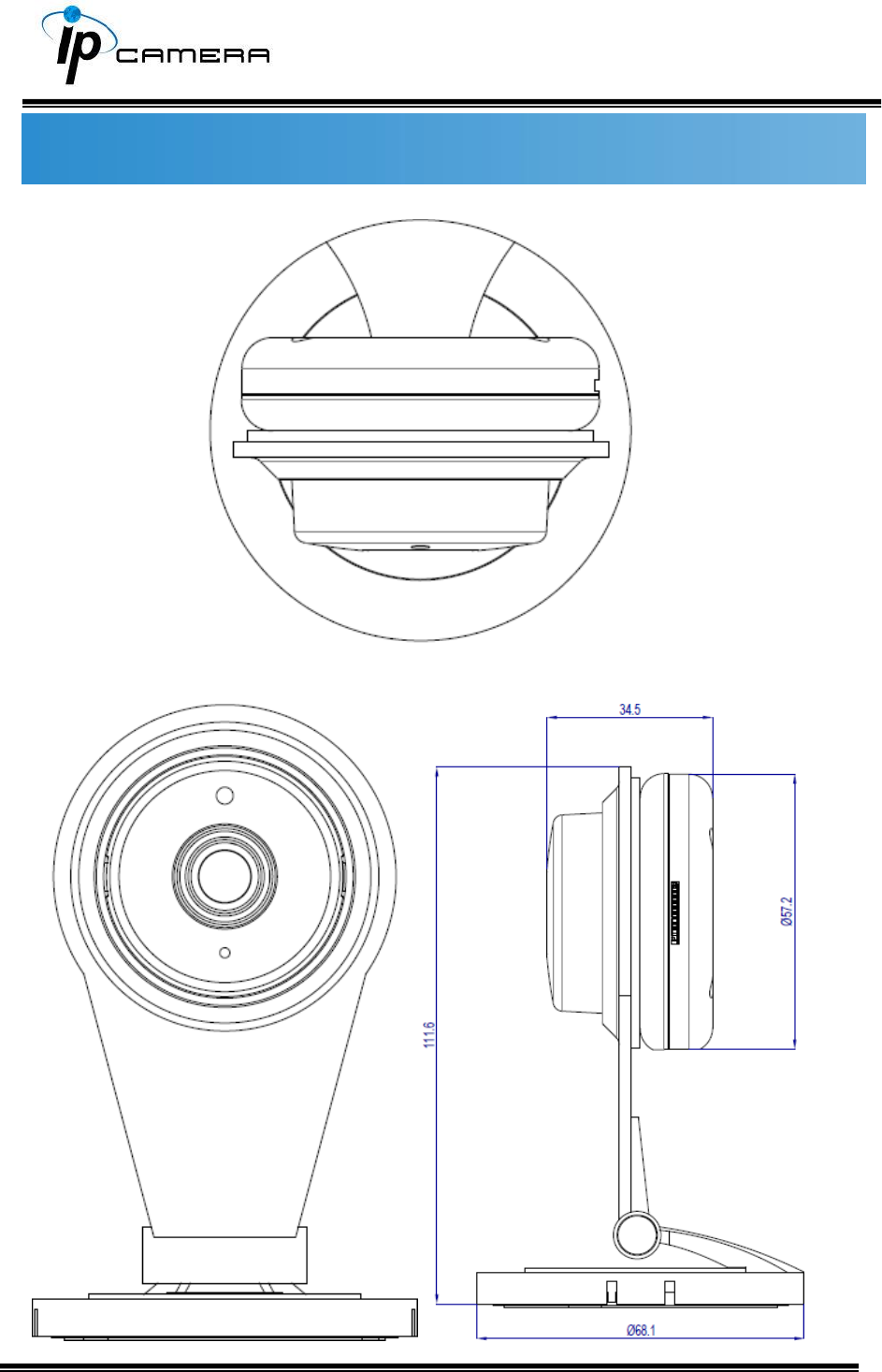
Dimensions
68.1mm x (H)111.6mm
Weight
100g
IR LEDs
LEDs
4 LEDs
IR distance
5m

Network
Network Protocol
IPv6, IPv4, HTTP, HTTPS, SSL, TLS , DNS , ICMP, IGMP,
ARP, RTSP/RTP/RTCP, TCP/IP, UDP, FTP, PPPoE, DHCP,
DDNS, NTP, UPnP, 3GPP, SAMBA, Bonjour
System
Video Resolution
1920x1080@30fps,1280x720@30fps, 640x480@30fps,
320x240@30fps
Video Adjust
Brightness, Contrast, Hue, Sharpness, AGC, Shutter
Time, Sense-Up, D-WDR , Flip, Mirror, Day&Night
Adjustable, De-noise , LDC
Features
Motion Detection, Privacy Mask, Anti Fog, Corridor
Mode, Push Video , P2P(Optional)
Dual Streaming
Yes
Image Snapshot
Yes
Full Screen Monitoring
Yes
Privacy Mask
Yes, 3 different areas
Compression Format
H.264/ M-JPEG
Video Bitrates Adjust
CBR, VBR
Motion Detection
Yes, 3 Different Areas
Triggered Action
Mail, FTP, Save to SD card, SAMBA
Pre/ Post Alarm
Yes, configurable
Security
Password protection, HTTPS encrypted data
transmission,
Firmware Upgrade
HTTP mode, can be upgraded remotely
Simultaneous Connection
Up to 10
Wireless
Wireless
802.11 b/g/n
Security
WEP,WPA-PSK,WPA2-PSK
Micro SD Card Management (Optional)
Recording Trigger
Motion Detection, IP check, Schedule
Video Format
AVI, JPEG
Video Playback
Yes
Delete Files
Yes
Web Browsing Requirement
OS
Windows 7, 8 , 10 ,XP, Microsoft IE 6.0 or above
Mobile Support
iOS 8 or above, Android 4.4.2 or above.
Hardware Suggested
Intel Dual Core 2.8G,RAM, 4GB, Graphic card: 128MB
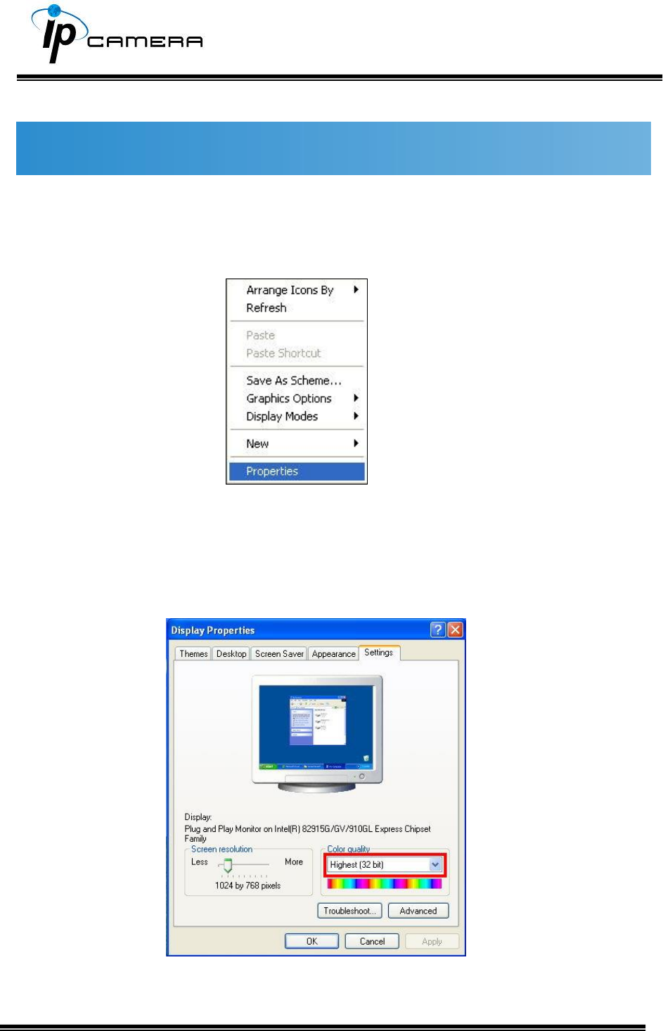
Monitor Settings
1. Right-Click on the desktop. Select Properties
2. Change color quality to highest: 32bit.
Hardware Installation
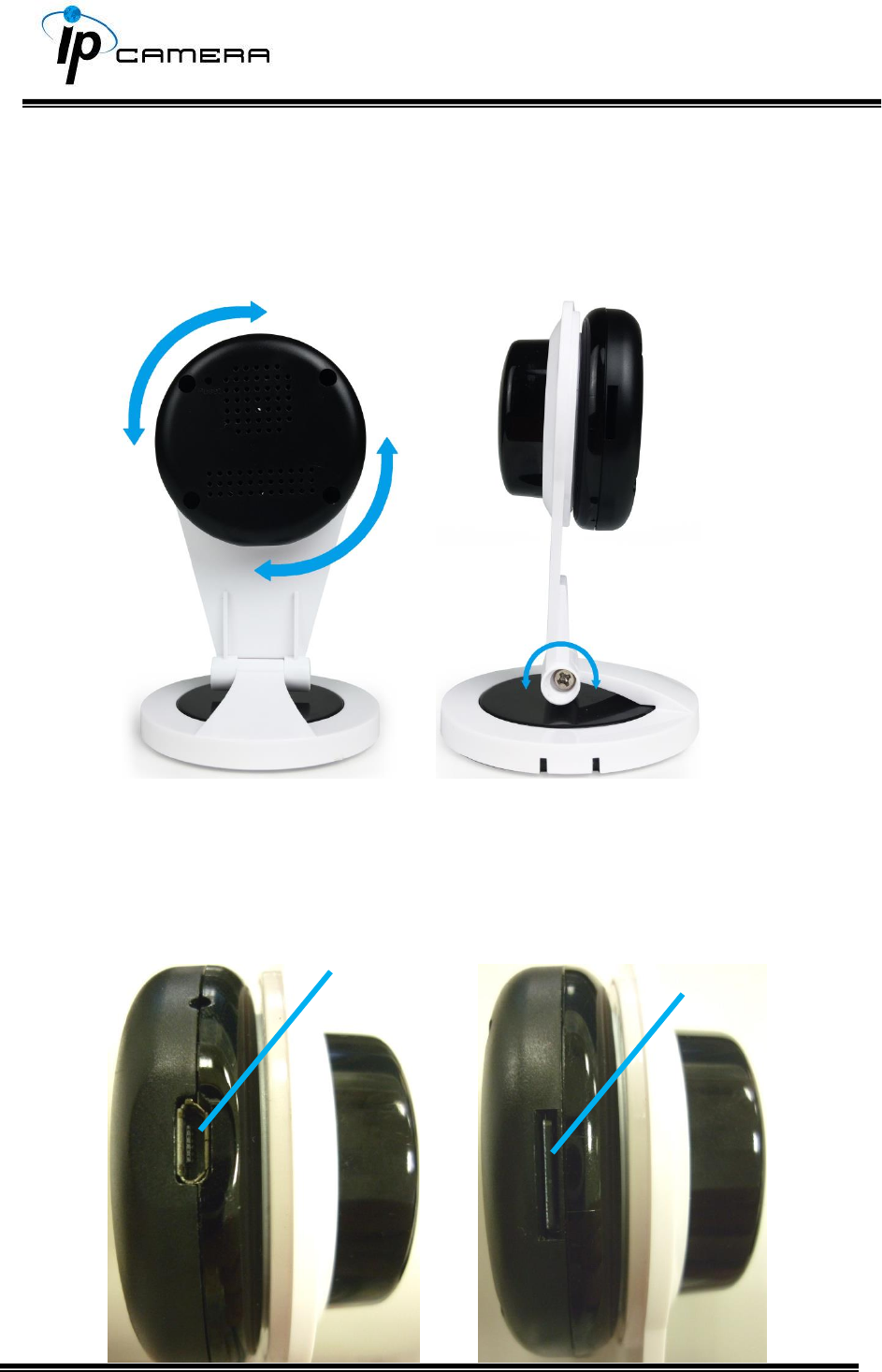
1. Angle Adjustment
You may be able to adjust the angle of the camera in various directions
when you are to install the MicroSD card or connect it to the adaptor.
Please refer to the image below.
2. Connector Instruction
The camera connectors are as below. Connect the power and the Ethernet
cable with the camera, and set it according to your network environment.
SD card slot
USB plug
IP Assignment
The camera does not work with RJ45 cable, therefore the user has to establish the
wireless connection via a router which shares the same LAN as the desktop
computer. The wireless network can be set up using SSID to perform the remote
operation.
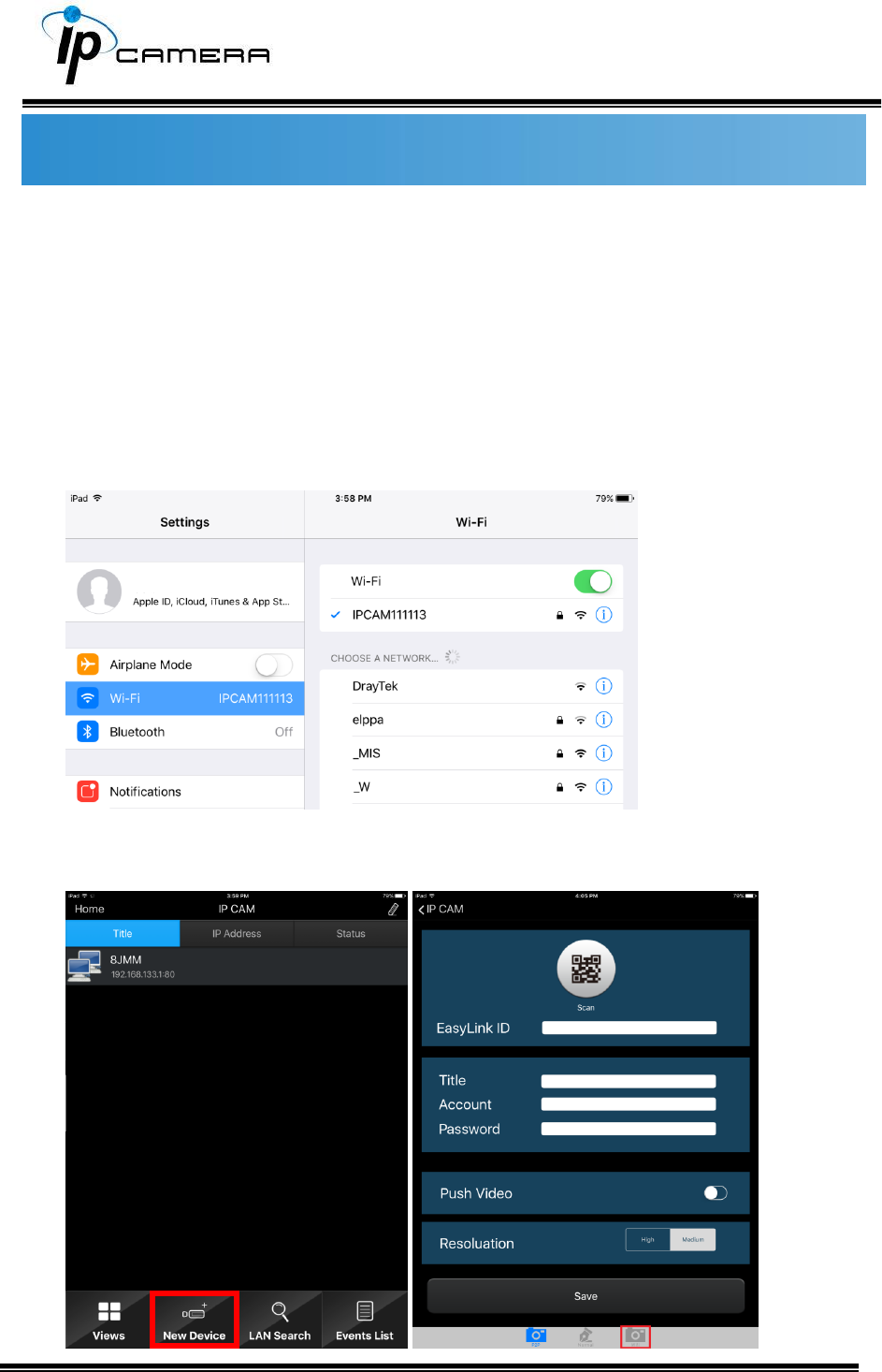
1. Once the camera is switched on, use the mobile device or tablet computer
to search for SSID through Wi-Fi and establish a connection. As the image
demonstrates below, the SSID name of the camera is IPCAM111113, which
is derived from the term “IP CAM”, with 111113 being the last 6 digits of
the MAC address of the device, hence the SSID name IPCAM111113.
Enter the default password “12345678” for accessing the SSID. Once the
connection has been successfully established, open the IPmotion APP, click on
New Device, and click on WiFi icon as framed in the image below.
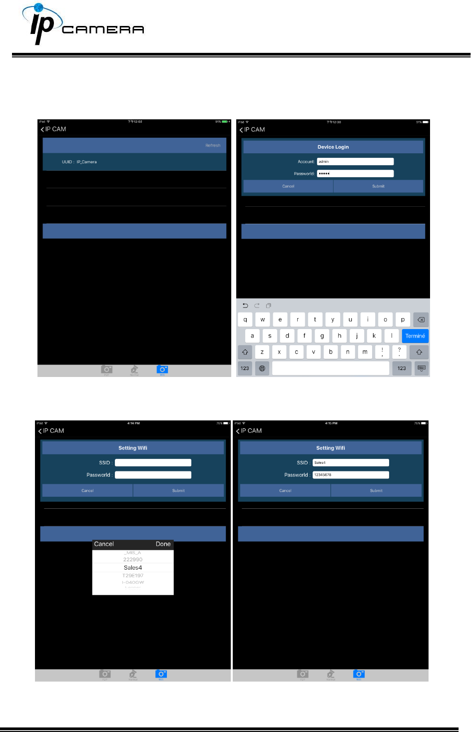
The same SSID name will be displayed in the WiFi interface which you have just
entered. Click on the SSID and enter its account name and password. (Account:
admin / Password: admin)
You will be asked to select the router which has been found online. Click on the
router which you would like to be connected with, key-in the password for the
router, and click on Submit.
Take the image below as the reference. Open the setting of the mobile device or
tablet computer, and select the same WiFi service which shares the same
connection of the camera.
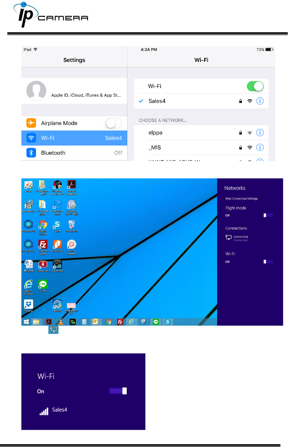
Now the camera is ready to be operated remotely from a desktop computer.
Click the icon at the right corner of the menu bar. The setup menu will pop up
from the right.
Turn on the Wi-Fi option by clicking on the bar with a mouse-click.
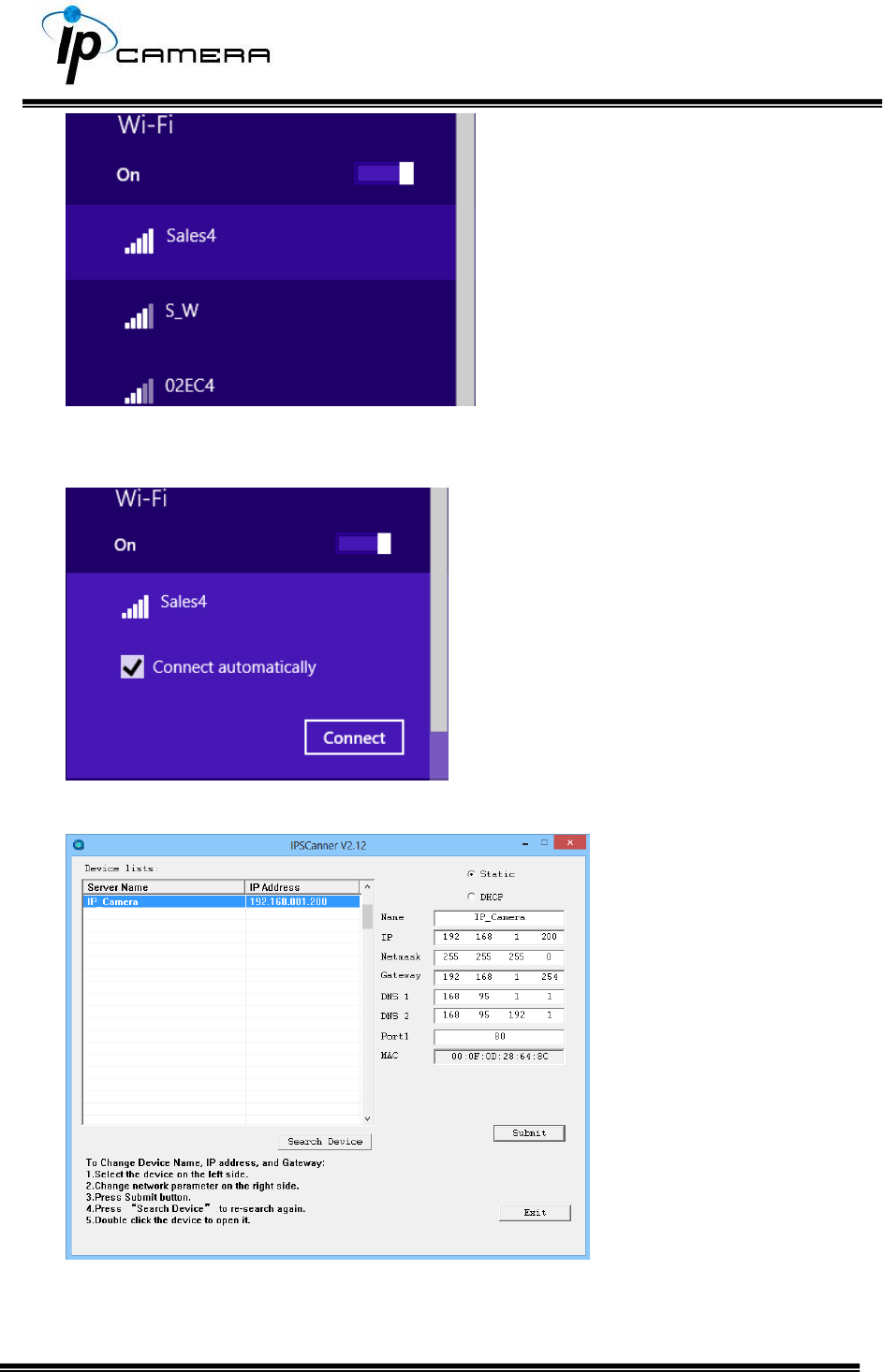
Select the same server that operates the wireless connection. In this case,
the Sales4 is the aimed server.
Click on Connect to allow the Wi-Fi connection to be established.
Execute IP Scanner, click on Search Device to find the expected IP camera or
simply open an IE browser and enter the IP address of the IP camera which
you would like to connect to.

Install ActiveX control
1. For users of IE 6.0 or above:
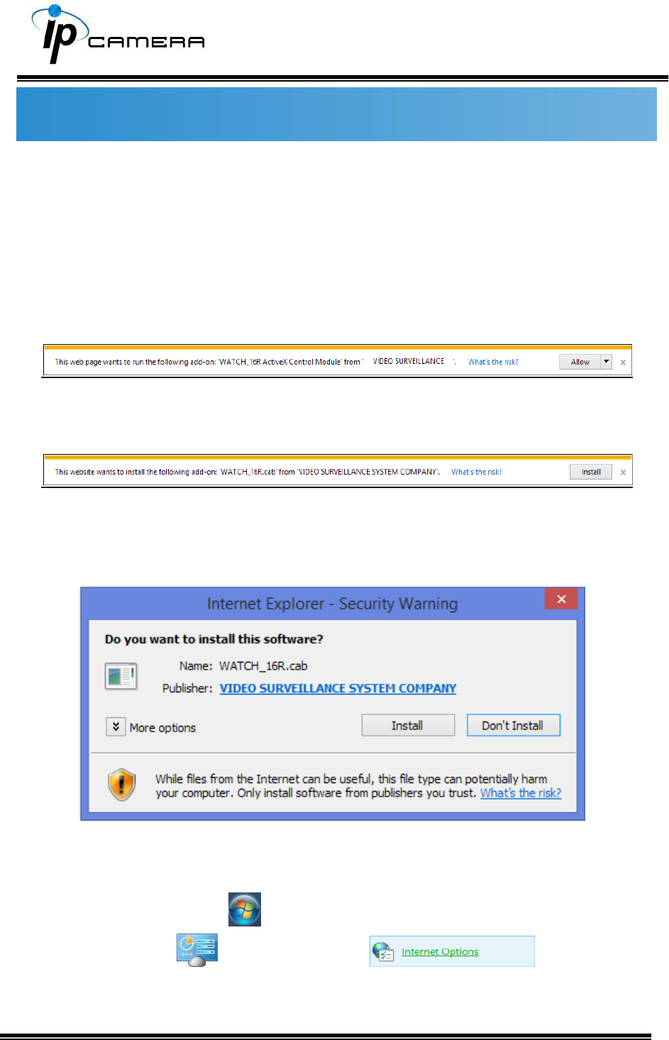
When viewing the camera video for the first time via IE, the browser will ask you to
install the ActiveX component.
Choose ‘Allow’,
Then choose ‘Install’.
Start installing the ActiveX component.
If the installation fails, please check the security settings in the IE browser.
Go to Start-Up Menu on the lower left corner of the Windows, select
Control Panel then Double-click on to access
to Internet Properties settings.
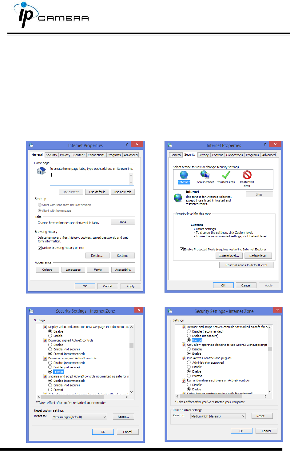
Starting from Internet Properties, proceeding step A and B:
A. Security Custom Level Security Settings Download unsigned
ActiveX controls Enable or Prompt (recommended).
B. Security Custom Level Security Settings Initialize and script
ActiveX controls not marked as safe Enable or Prompt
(recommended).
1
2
3
4
5
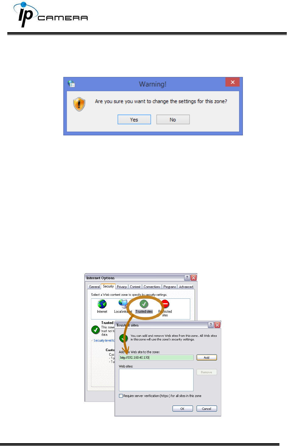
When popup the following dialogue box, click Yes.
2. You can choose another way:
Go to: IE→Tools → Internet Options… → Security Tab → Trusted sites → Add the IP
address and click OK.
In the site list you can key one single IP address or a LAN address. For example, if you
add 192.168.21.*, all the IP address under 21.* on the LAN will be regarded as trusted
sites.
2. To Non-IE Web Browser Users
If you use Firefox or Google chrome to access the IP camera but fails to watch the live
video, please follow the steps to install necessary tools:
(The following pictures are based on chrome.)
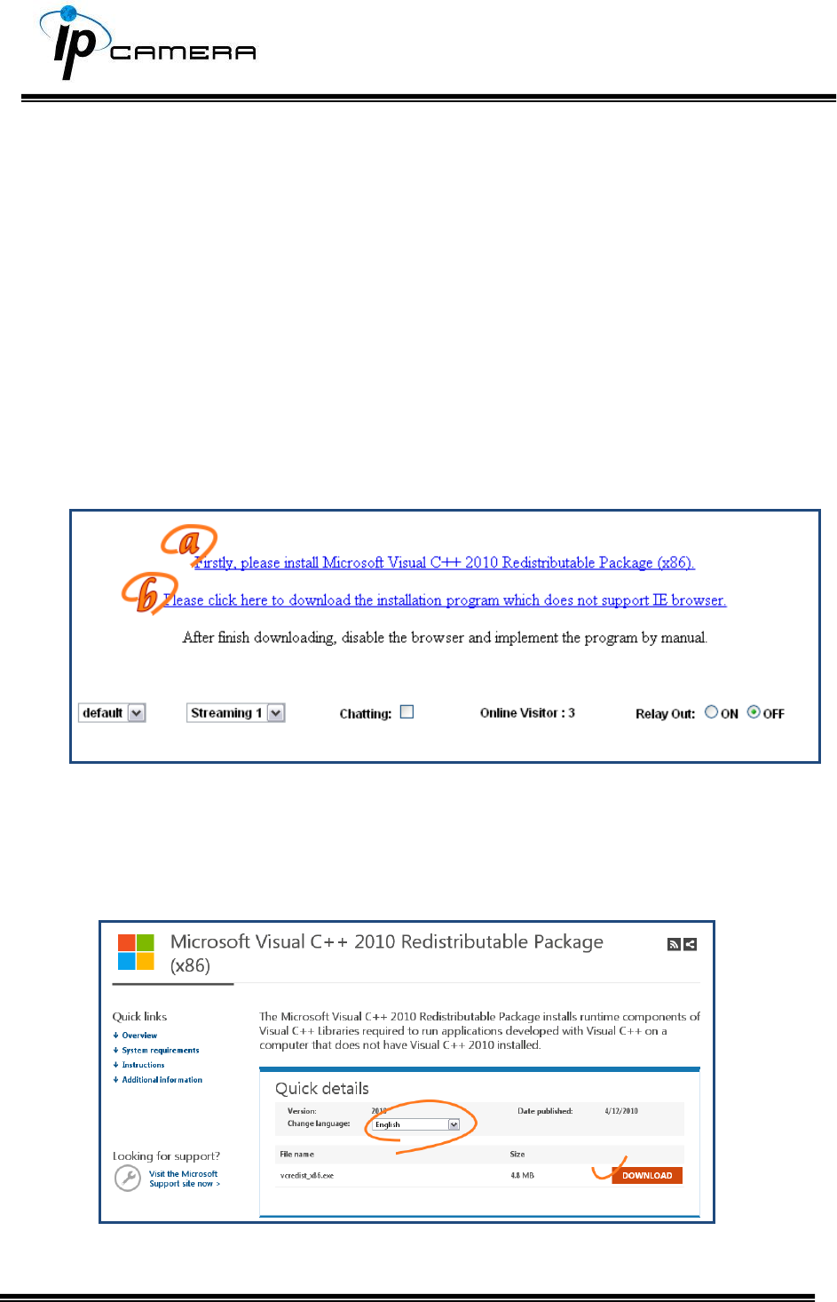
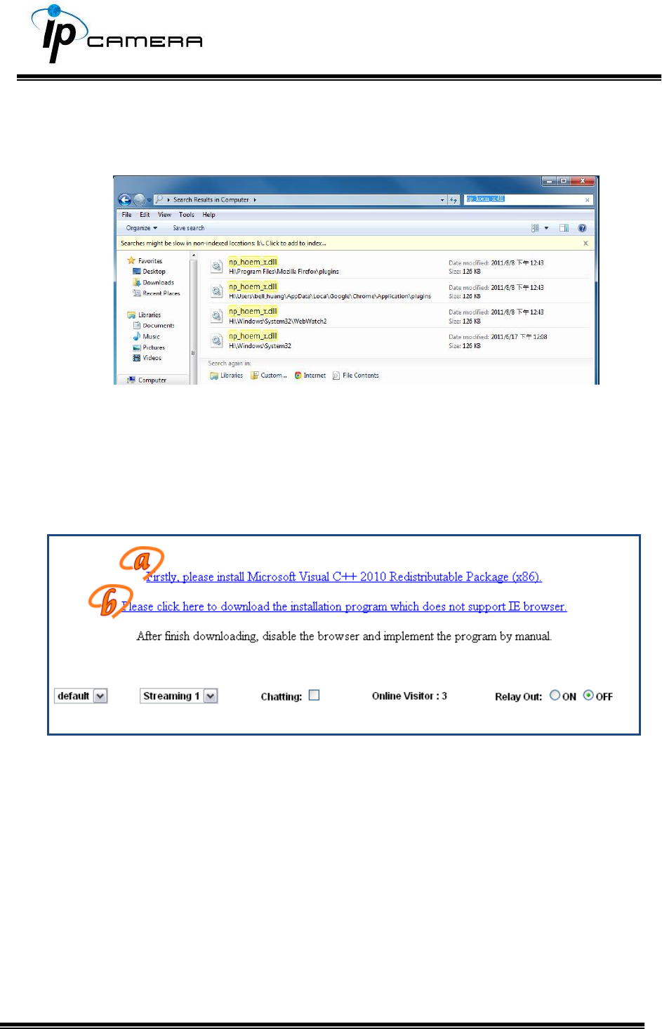
a. You may see the prompt message as the picture below. Click the link:
Firstly, please install Microsoft Visual C++ 2010 Redistributable Package (x86).
The link will conduct you to the Microsoft official site where you can download the
tools. Please select the language and click download.
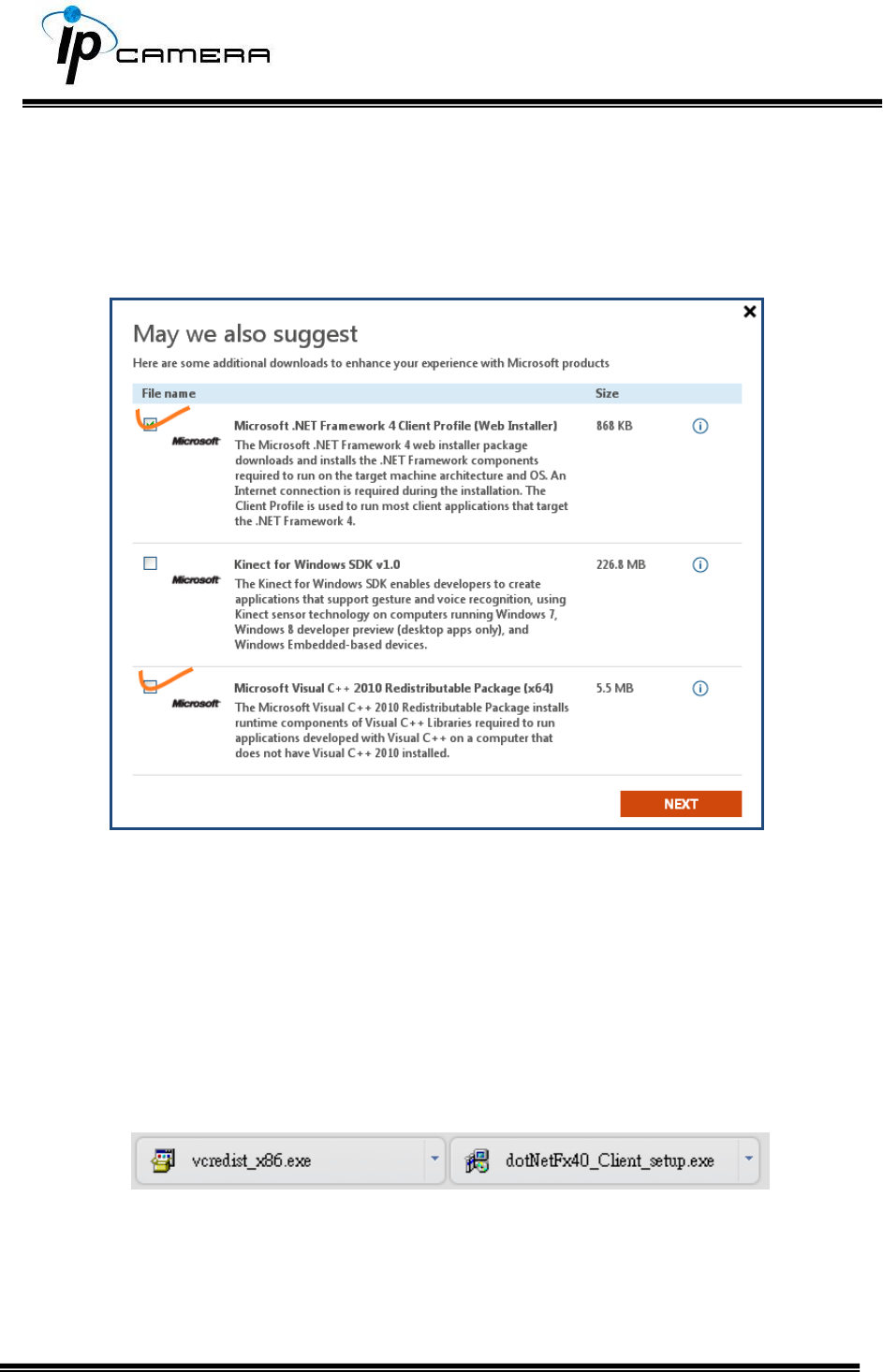
In the pop-up window, please tick the first and the third file as the picture below.
Click Next to download both Microsoft .NET Framework 4 Client Profile (Web
Installer) and Microsoft Visual C++ 2010 Redistributable Package (x64).
After finishing downloading, execute the two files respectively to install them. The
windows may ask you to reboot the PC when the installation is finished.
b. Then, click the second link Please click here to download the installation program
which does not support IE browser to download Setup ActiveX.
After finishing downloading, execute the files to install ActiveX. Then restart the
browser.
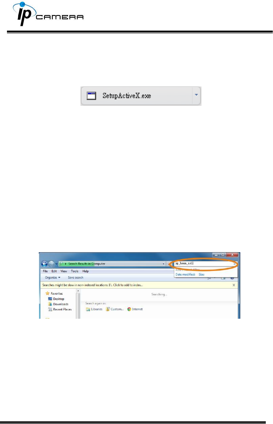
c. If you execute the steps above but still cannot see live video normally, please try
the following solution:
Search for the file np_hoem_x.dll in your system disk. For Windows XP users, please
go to Start → Search → Search for All files and folders and key-in np_hoem_x.dll.
For Windows 7 users, please use the search bar on the top-right of the Windows
Explorer.
Delete all the files named np_hoem_x.dll. They're the ActiveX control tools installed
in your computer, but the old version of ActiveX might not be compatible with the
new version of the browser. Therefore, they need to be deleted in order to install the
latest ActiveX control.
Start your web browser, and repeat the step 2-b: Download the installation program
which does not support IE browser to download and install ActiveX.
Live Video
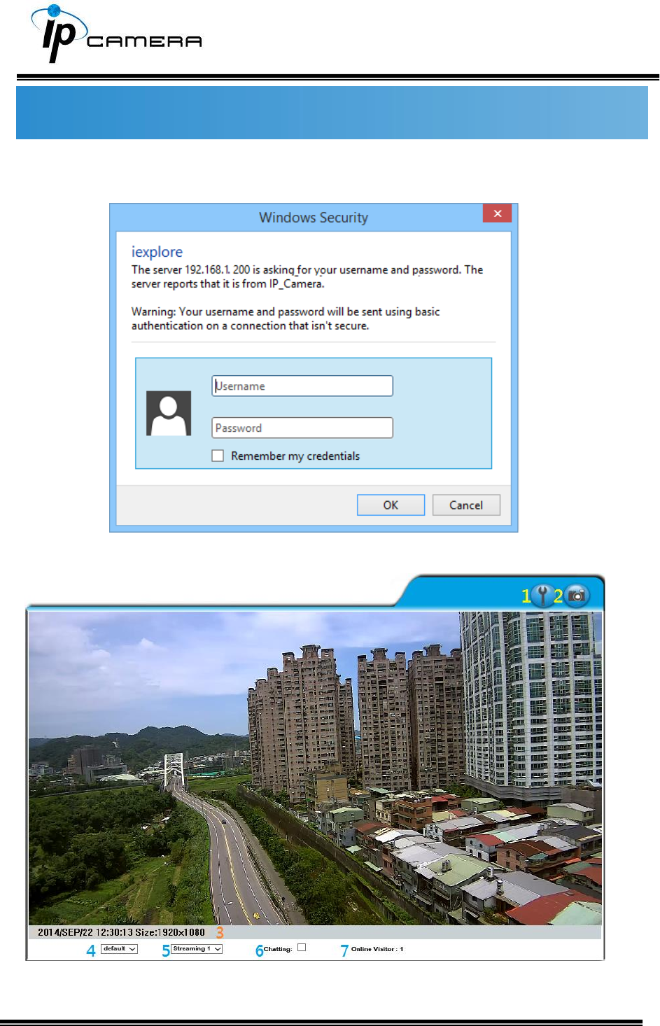
Start an IE browser, type the IP address of the IP camera in the address field. It will
show the following dialogue box. Key-in the user name: admin and password: admin.
When the IP Camera is successfully connected it shows the following interface.
1. Get into the administration page.
2. Video Snapshot.
3. Show the system time, video resolution, and video refreshing rate.
4. Adjust image: 1/2x, 1x, 2x.
5. Streaming source: If the streaming 2 is closed, this function will not be
displayed.
6. Tick on Chatting for enabling two-way audio.
7. Shows how many people are connected to this IP camera.
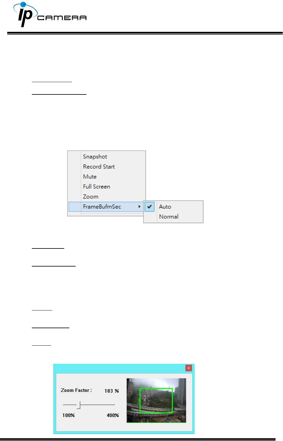
Right-Click the mouse on the video, a menu will pop up.
1. Snapshot: Save a JPEG picture.
2. Record Start: Record the video in the local PC. It will ask where to save
the video. To stop recording, right-click again and Select Record Stop.
The video format is AVI. Use Microsoft Media Player to play the recorded
file.
3. Mute: Turn-off the audio. Click again to turn on it.
4. Full Screen: Full-screen mode.
5. Zoom: Enable the zoom-in and zoom-out functions. First, select Enable
digital zoom option within the pop-up dialogue box and then drag and
drop the bar to adjust the zoom factors.

6. Frame Buffm Sec: T This function aims to build a temporary buffer to
accumulate several video frames in a LAN network environment. It can
make video streaming smooth when the network speed is slow.
Select Auto to allow this function automatically help fix the streaming
performance whenever the video happens to be lagging.
Select Normal to play the video data based on the current network
streaming performance. (Note: the lagging of the video displayed will not
be seen as a result of the actual video data)
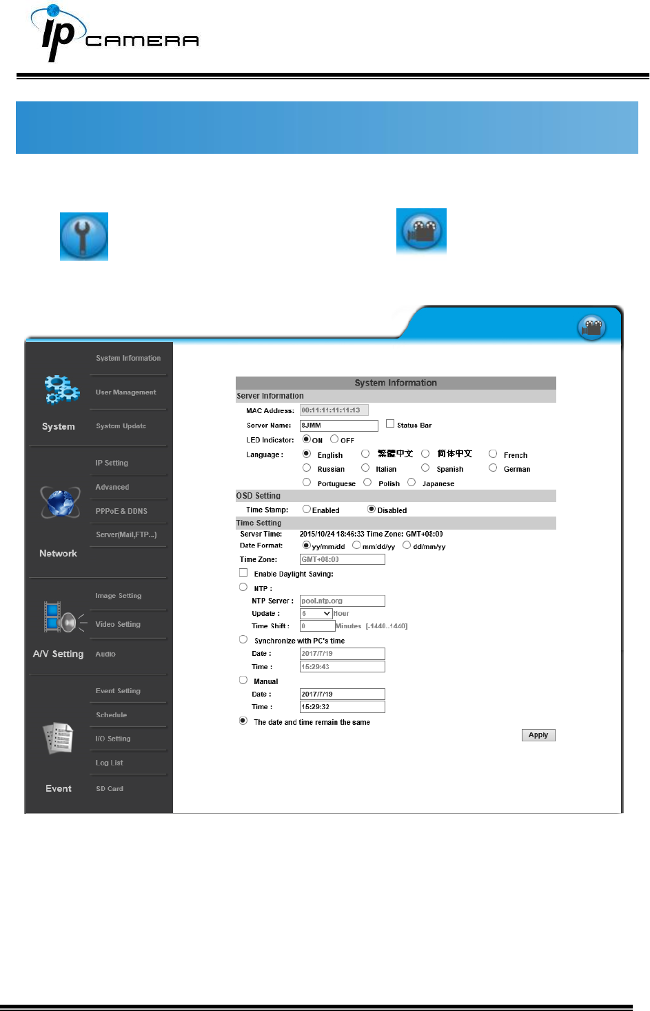
System
Click to get into the administration page. Click to go back to the live
video page.
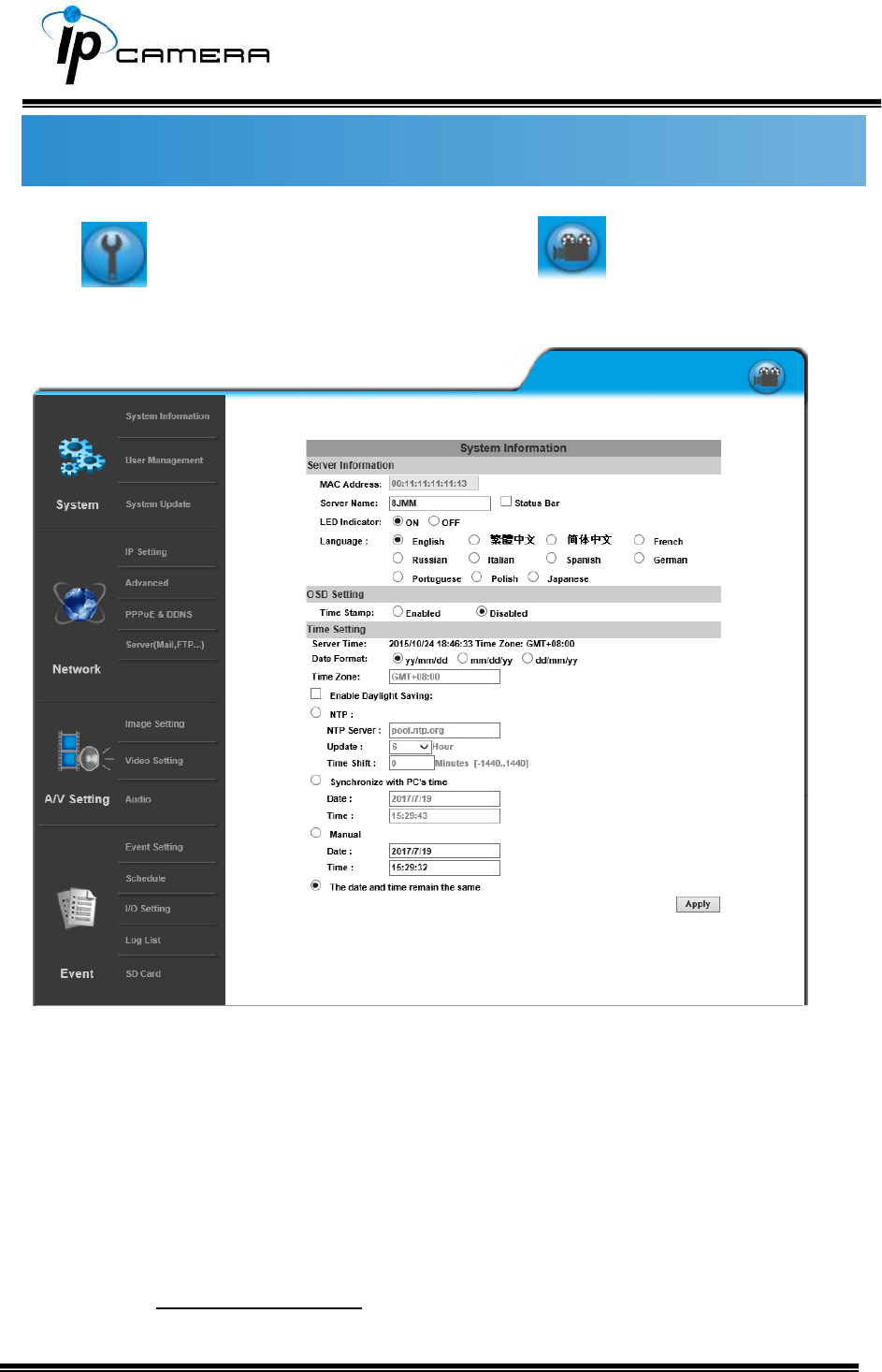
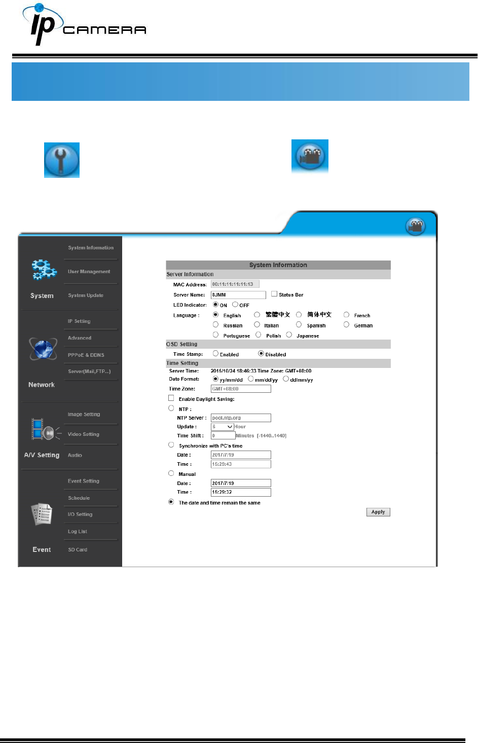
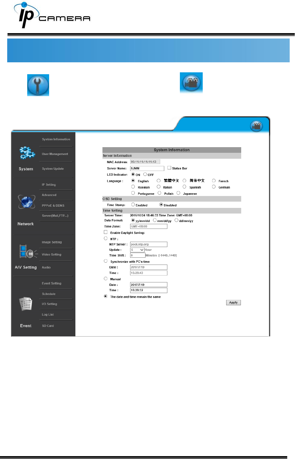
I. System Information
a. Server Information
Set up the camera name, language, and the camera time.
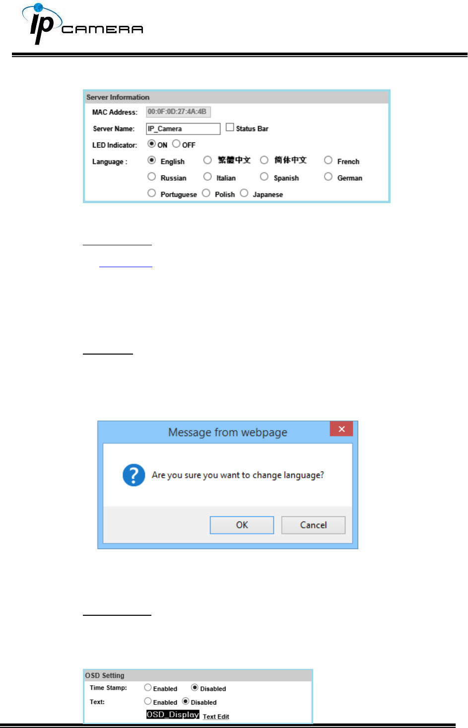
1. Server Name: This is the Camera name. This name will be shown on
the IP Scanner.
2. LED Indicator: Turn on/off the LED indicator on the camera.
3. Language: English and other languages can be selected. When a
language preference is selected, the following dialogue box will pop up
to confirm the change.
b. OSD Setting
Select a position where the date & time stamp / text are displayed on
the screen.
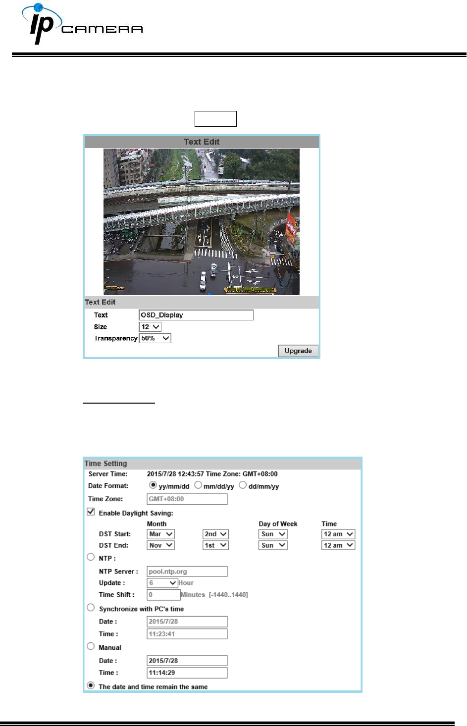
Click Text Edit for editing the OSD content, including text size and
transparency. Click the Upgrade button to apply the settings.
c. Time Setting
Select between NTP, Synchronize with PC’s time, Manual, The date
and time remain the same for setting the server time.
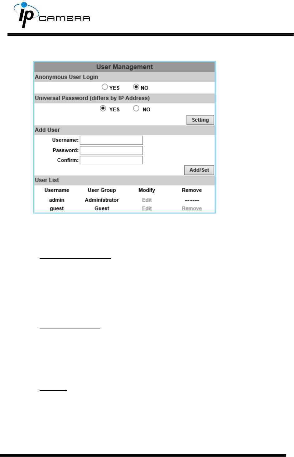
II. User Management
The IP Camera supports three different users: administrator, general, and
anonymous user.
1. Anonymous User Login
Select Yes for allowing access to watch live video of the IP camera without
having to enter username and password. Yet when entering the
configuration page of the IP camera, the system will do otherwise. Select
No for requiring a username and login to access the camera.
2. Universal Password
Select Yes for allowing login to this IP camera by universal password.
Please refer to Universal Password chapter for more explanations.
Select No for disabling universal password.
3. Add user
Type the user name and password, then click Add/Set. The guest user
can only browse live video page and is not allowed to enter the
configuration page. Click “Edit” or “Remove” in the user list to modify
them. The system will ask you to key-in the password in the pop-up
window before you edit the user information.
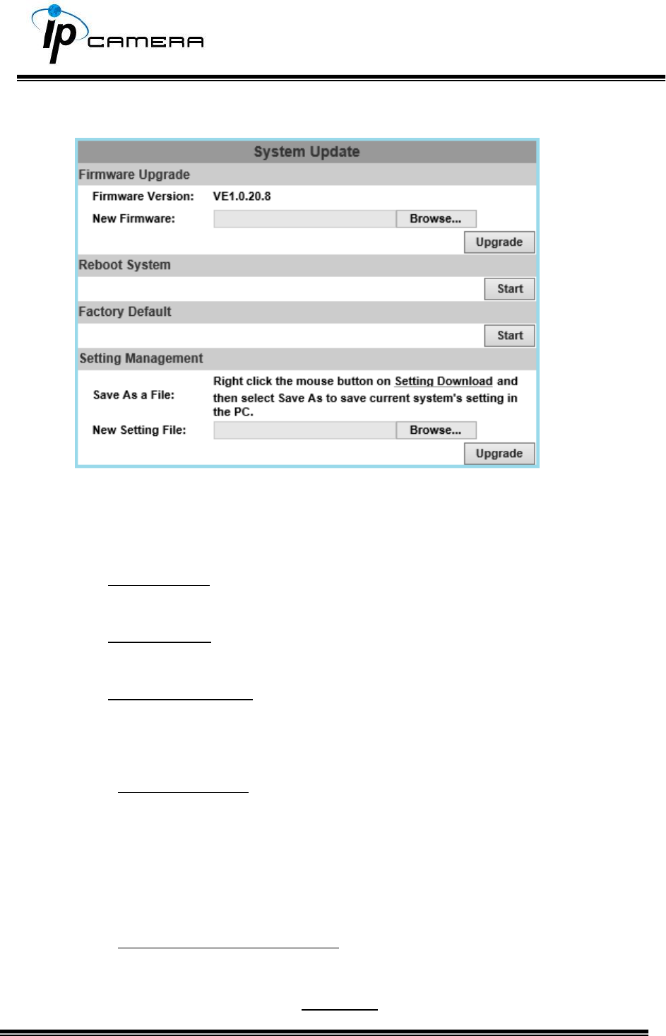
III. System update
a. To update the firmware online, click Browse… to select the firmware.
Then click Upgrade to proceed.
b. Reboot system: re-start the IP camera
c. Factory default: delete all the settings of this IP camera.
d. Setting Management: The user can download the current settings to PC,
or upgrade from previous saved settings.
1. Settings download
Right-click the mouse button on Setting Download Select Save
AS… to save current IP Camera settings in PC Select saving
directory Save
2. Upgrade from previous settings
Browse search previous settings open upgrade Settings
update confirm click index.html. for returning to the main page.
Network
Click to get into the administration page. Click to go back to the live
video page.
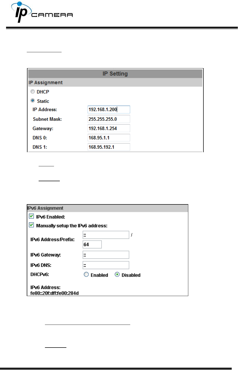
I. IP Settings
IP Assignment
The IP Camera supports DHCP and static IP.
a. DHCP: The IP Camera will get all the network parameters automatically.
b. Static IP: Type-in the IP address subnet mask, gateway, and DNS.
IPv6 Assignment
Enable DHCPv6 to configure the following IPv6 address settings:
Manually setup the IPv6 address: Key-in the Address, Gateway, and
DNS.
DHCPv6: If you have a DHCPv6 server, enable it to assign the IPv6
automatically. The assigned IP address will be displayed beside the
column.
Automatically generated IPv6 Address: Indicates a virtual IPv6
address generated automatically by the IP camera. This virtual IPv6
address cannot be used on WAN.
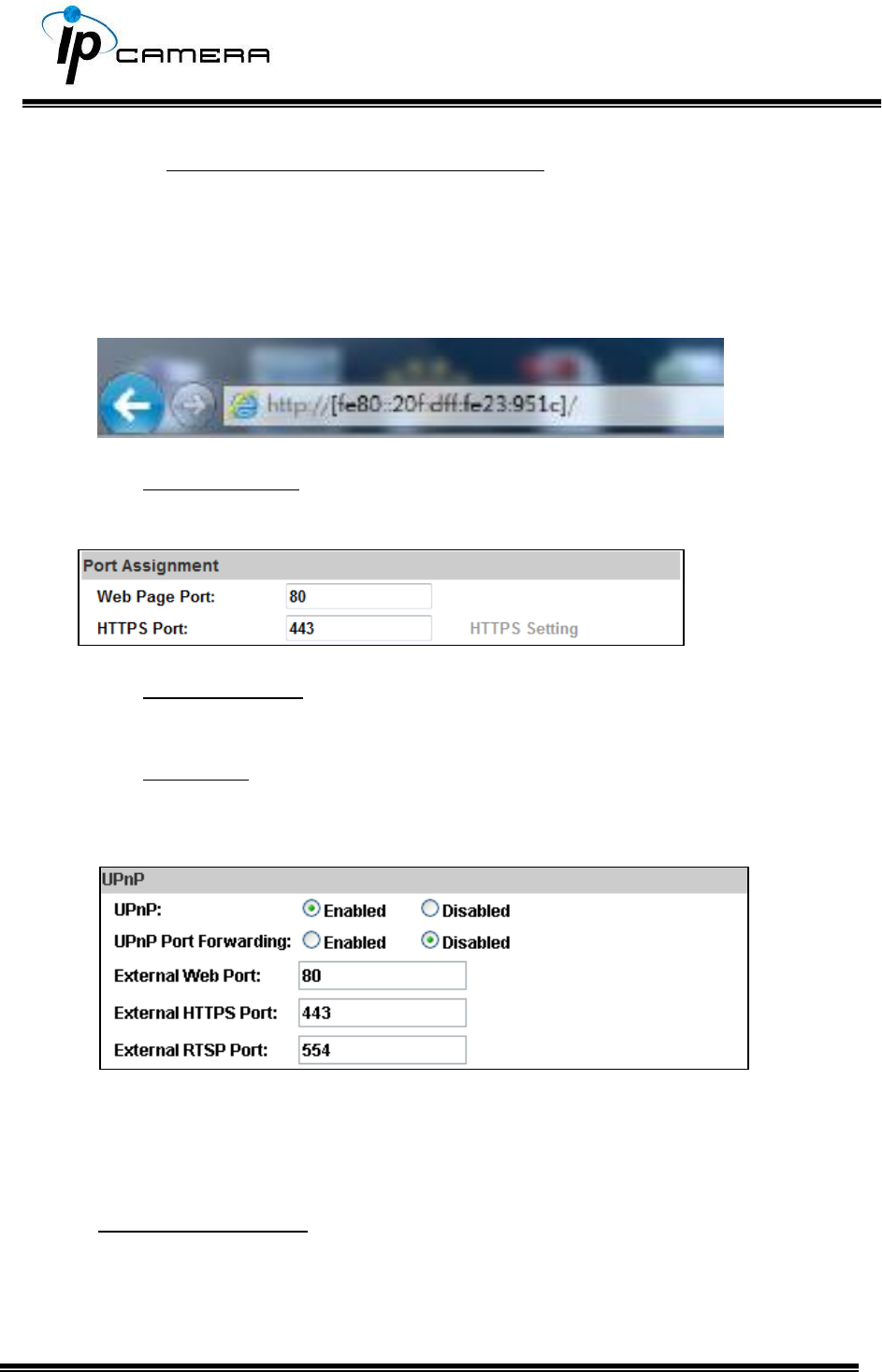
To use IPv6 address to access the IP camera, open the web browser, and key-
in the [IPv6 address] in the address bar. The [ ] parentheses mark is
necessary.
a. Port Assignment: The user might need to assign a different port to avoid
conflicts when setting up the IP.
b. Web Page Port: setup the web page connecting port and video
transmitting port (Default: 80)
c. HTTPs Port: setup the https port(Default: 443)
UPnP
This IP camera supports UPnP, if this service is enabled on your computer, the
camera will automatically be detected and a new icon will be added to My
Network Places.
UPnP Port Forwarding:Enable UPnP Port Forwarding for accessing the IP
Camera from the Internet; this option allows the IP Camera to open ports on
the router automatically so that video streams can be sent out from a LAN.
There are three external ports for being set: Web Port, Http Port and RTSP
port. To utilize of this feature, make sure that your router supports UPnP and
is activated. Note: UPnP must be enabled on your computer.
Please follow the procedure to activate UPnP:
<Approach 1>
i. open the Control Panel from the Start Menu
ii. Select Add/Remove Programs
iii. Select Add/Remove Windows Components and open Networking
Services section
iv. Click Details and select UPnP to setup the service.
v. The IP device icon will be added to My Network Places.
vi. The user may double click the IP device icon to access IE browser
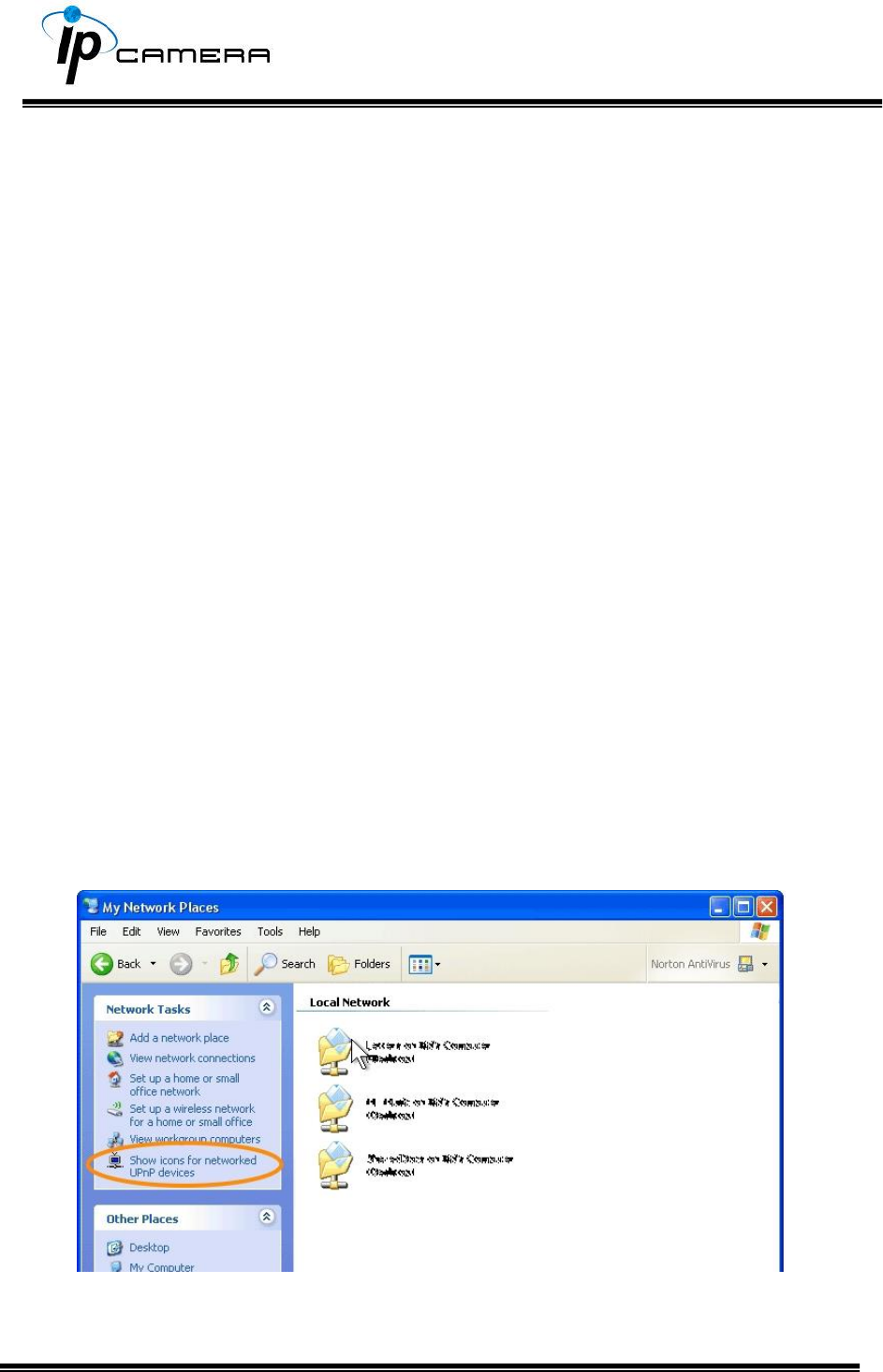
<Approach 2>
i. Open My Network Space
ii. Click Show icons for networked UPnP devices in the tasks column on
the left of the page.
iii. Windows might ask your confirmation for enabling the components.
Click Yes.
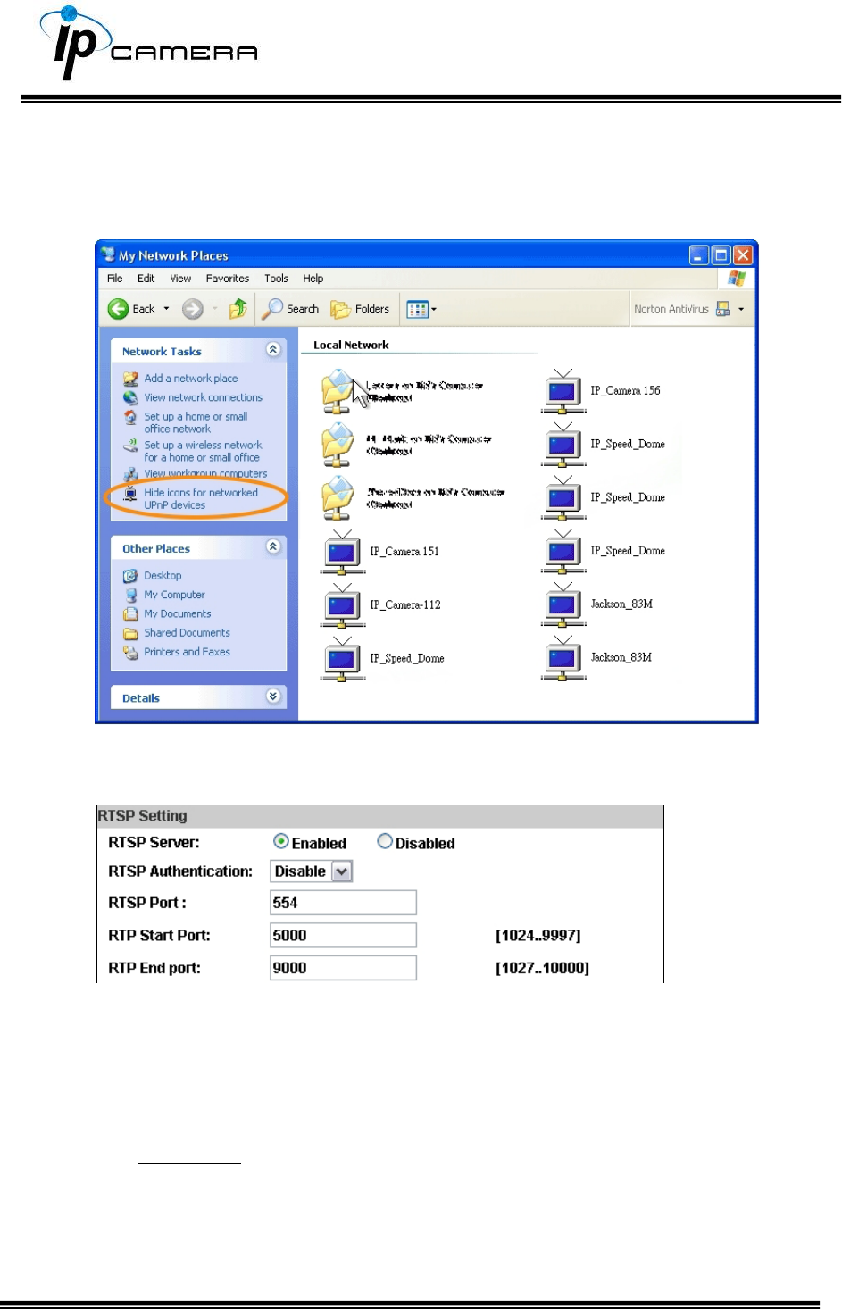
iv. Now the IP device is displayed under the LAN. Double-click the icon to
access the camera via web browser. To disable the UPnP, click Hide
icons for networked UPnP devices in the tasks column.
RTSP Setting
If you have a media player that supports RTSP protocol, you can use it to
receive video streaming from the IP camera. The RTSP address can be set for
two streamings respectively.
i. RTSP Server: enable or disable
Disable means everyone who knows your camera IP Address can link to
your camera via RTSP. No username & password required.
Under Basic and Digest authentication mode, the camera asks for a
username and password before allows access.
The password is transmitted as a clear text under basic mode, which
provides a lower level of security than under digest mode.
Make sure your media player supports the authentication schemes.
ii. RTSP Port: setup port for RTSP transmitting (Default: 554)
iii. RTP Start and End Port: in RTSP mode, you can use TCP and UDP for
connecting. TCP connection uses RTSP Port (554). UDP connection uses
RTP Start and End Port.
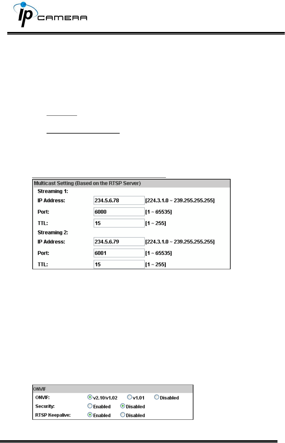
Multicast Setting (Based on the RTSP Server)
Multicast is a bandwidth conservation technology. This function allows
several users to share the same packet sent from the IP camera.
For using Multicast, appoint here an IP Address and port. TTL means the life
time of packet, the larger the value is, the more users can receive the packet.
For using Multicast, be sure to enable the function Force Multicast RTP via
RTSP in your media player. Then key in the RTSP path of your camera:
rtsp ://( IP address)/ to receive the multicast.
ONVIF
i. Choose your ONVIF version and settings.
Under ONVIF connection, the video will be transmitted by RTSP. Be sure
to enable the RTSP server in IP setting, otherwise the IP Camera will not
be able to receive the video via ONVIF.
ii. Security:
By selecting Disable, the username and password are not required for
accessing the camera via ONVIF. By selecting Enable the username and
password are necessary.
iii. RTSP Keepalive:
When the function is enabled, the camera checks once in a while if the
user who is connected to the camera via ONVIF is still connected. If the
connection has been broken the camera will stop transmitting video to
the user.
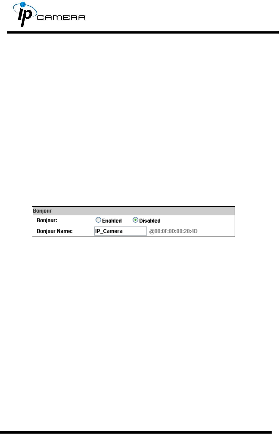
Bonjour
This function allows Apple systems to connect to this IP camera. On Bonjour
Name key-in the name here.
The web browser Safari also has a Bonjour function. Tick Include Bonjour in
the bookmark setting, for the IP camera to appear under the bonjour
category. Click the icon to connect to the IP camera.
The Bonjour function on Safari browser doesn't support HTTPS protocol. If on
the camera you select https, the camera will appear on Safari's bookmarks
but it cannot be accessed.
Take as a reference to the following image:
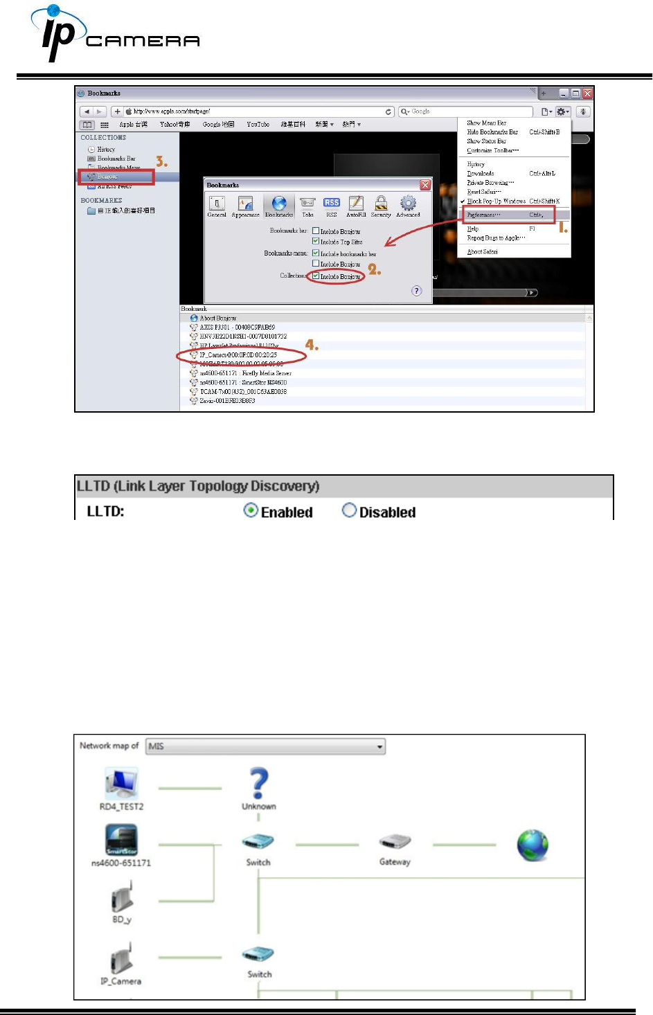
LLTD
If your PC supports LLTD, enable this function for allowing checking the
connection status, properties, and device location (IP address) in the network
map.
If the computer is running Windows Vista or Windows 7, you can find LLTD
through the path:
Control Panel → Network and Internet → Network and Sharing Center →
Click See full map.
II. Advanced
a. Https (Hypertext Transfer Protocol Secure)
When the users access cameras via Https protocol, the transmitted
information will be encrypted, increasing the security level.
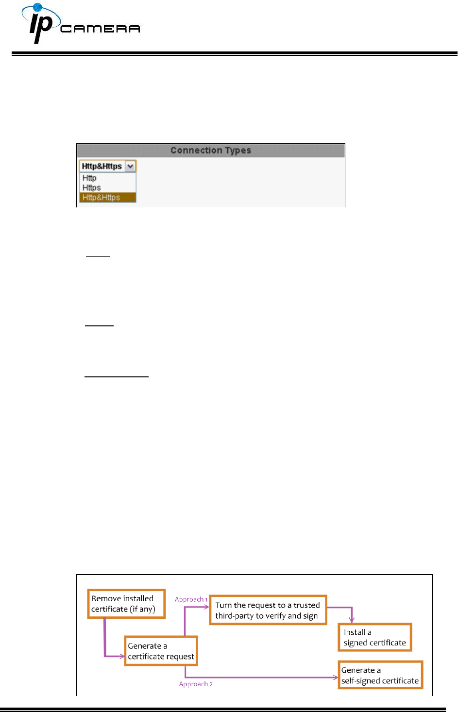
Select the connection type:
• Http: the user can access the camera via the Http path but cannot
access it via the Https path.
• Https: the user can access the camera via the Https path but cannot
access it via the Http path.
• Http & Https: Both the Http and Https path can be used to access the
camera. When you change the connection type settings, it may cause
connection error or disconnection error if you switch the protocol
directly. Therefore, Http & Https mode is necessary.
If you want to change from Http to Https, please switch to Http & Https
mode first, and then switch to Https mode and vice versa.
The Https protocol has a verifying mechanism. When the user access a
website via Https, the browser will check the certificate of that domain
and verify its trustiness and security.
Certificate generation process:
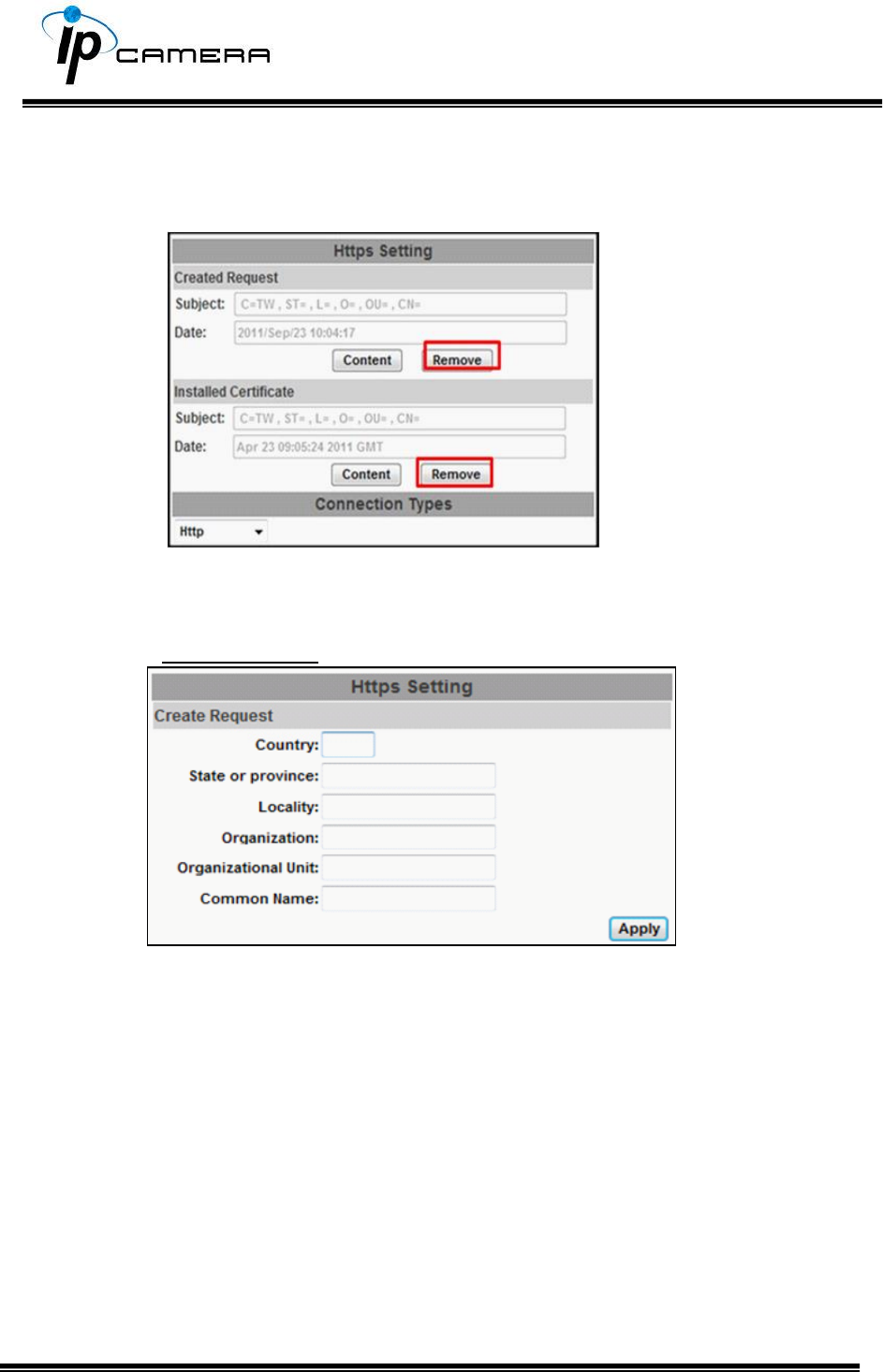
• Remove the existing certificate: Before you generate a new certificate,
please remove the installed one. Select the Http connection type and
click Remove. If a dialog box pops up to ask you to confirm, click Yes.
• Created Request: Fill-in the following form and click apply.
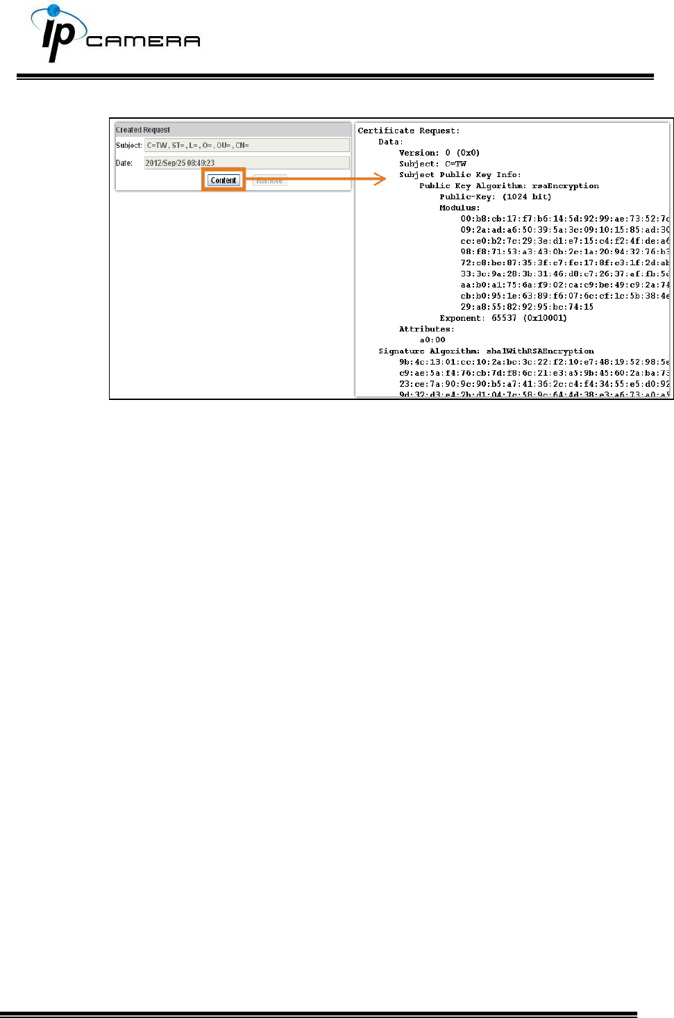
• After generating a certificate request, if you choose to turn it and
verified by a trusted third-party, click Content and copy all the request
content.
• According to the certificate source, there are two ways to install the
certificate:
If you had sent the certificate request for signing and receiving a signed
certificate, click browse and find the certificate file in your computer.
Click Apply to install it.
If you choose to generate a self-signed certificate, fill-in the following
forms and set the validity day, click Apply to finish installed it.
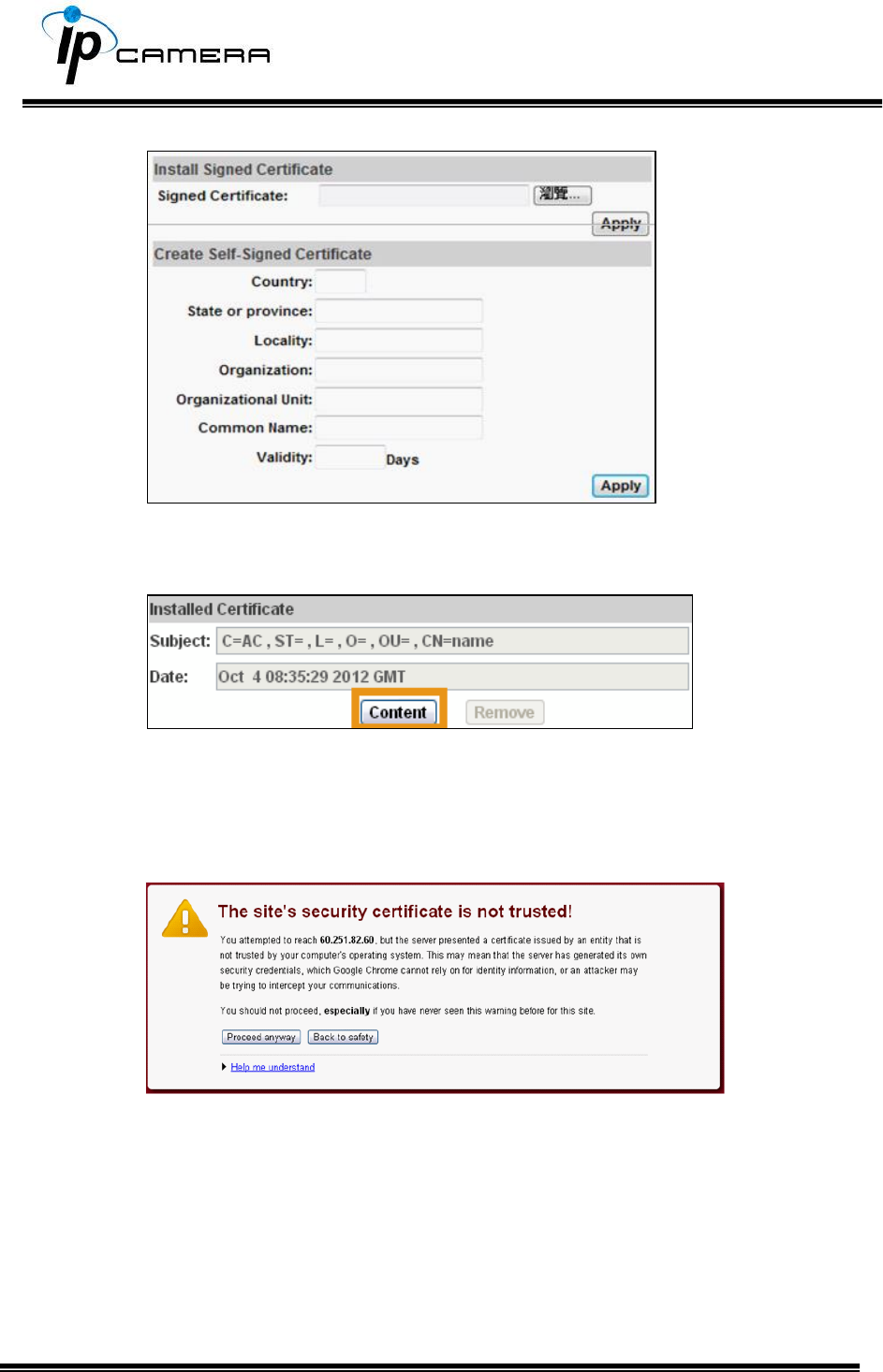
After finishing the installation, click on Content to call out and check the
certificate content.
To use Https to access the camera, open your browser, and key-in
https:// (IP address)/ in the address bar. Now your data will be
transmitted via encrypted communications. The browser will check your
certificate status. It might show the following warning message:
Meaning that certificate is self-signed or signed by a distrusted
institution. Click Proceed anyway to return to the camera page.
b. SNMP (Simple Network Management Protocol)
1. SNMPv1 or SNMPv2: write the name of both Write
Community and Read Community.
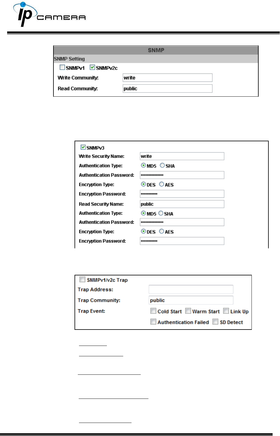
2. SNMPv3: Set the Security Name, Authentication Type,
Authentication Password, Encryption Type, Encryption
Password of Write mode and Read mode.
3. Enable SNMPv1/SNMPv2 Trap for detecting the Trap server.
Please set what event needs to be detected.
• Cold Start: The camera starts up or reboots.
• Setting changed: The SNMP settings have been
changed.
• Network Disconnected: The network connection is broken down
(The camera will send trap messages after the network is
connected again).
• V3 Authentication Failed: A SNMPv3 user account tries to get
authentication but failed. (Due to incorrect password or
community)
• SD Insert / Remove: A Micro SD card is inserted or
removed.
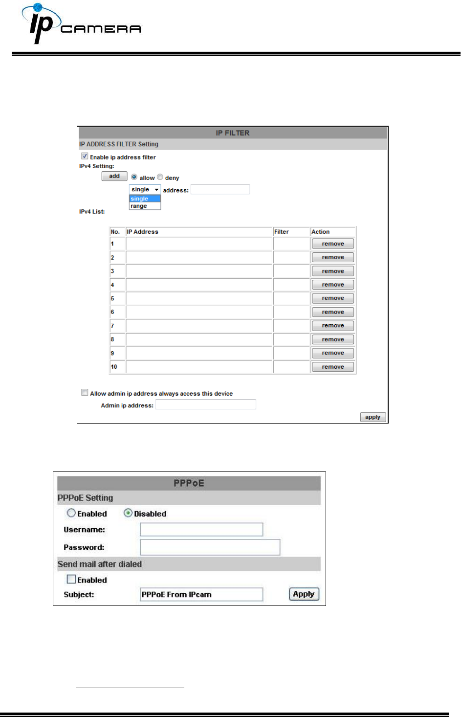
c. Access list:
Enable IP address filter for setting the IP addresses which allows or
denies this camera. There are two options: single and range.
III. PPPoE & DDNS
a. PPPoE: Select Enabled to use PPPoE. Key-in the the Username and
password for ADSL connection.
Send mail after dialed: When connected to the internet, the camera will
send a mail to a specific mail account.
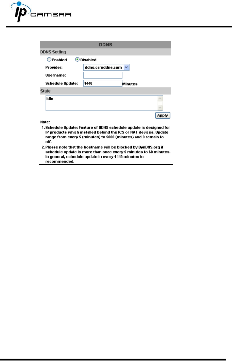
b. DDNS (camddns example):
Enable this service
Key-in the username.
IP schedule update. Default: 5 minutes
Click Apply.
DDNS Status
(1) Updating: Information update
(2) Idle: Stop service
(3) DDNS registration successful, can now log by
http://<username>.ddns.camddns.com: Register successfully.
(4) Update Failed, the name is already registered: The user name has
already been used. Please change it.
(5) Update Failed; please check your internet connection: Network
connection failed.
(6) Update Failed, please check the account information you provided:
The server, user name, and password may be wrong.
IV. Server Settings
There are three server types available: Email, FTP and SAMBA. Select the
item for display detailed configuration options. You can configure either one
or all of them.
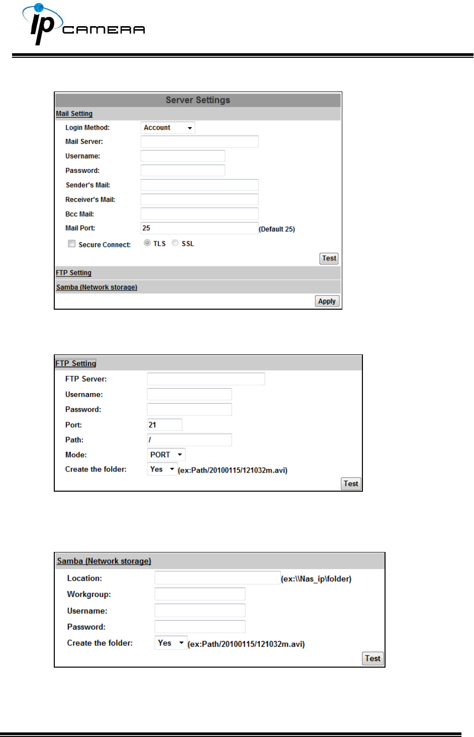
To send out the video via mail of FTP, please set up the configuration first.
FTP
To send out the video via mail of FTP, please set up the configuration.
Samba
Select this option to send the media files via a neighbor network when an
event is triggered.
Click Apply to save the setting, then use Test button to test the server
connection. A message box will tell you OK! if it works, and a test document
will be created in the location.
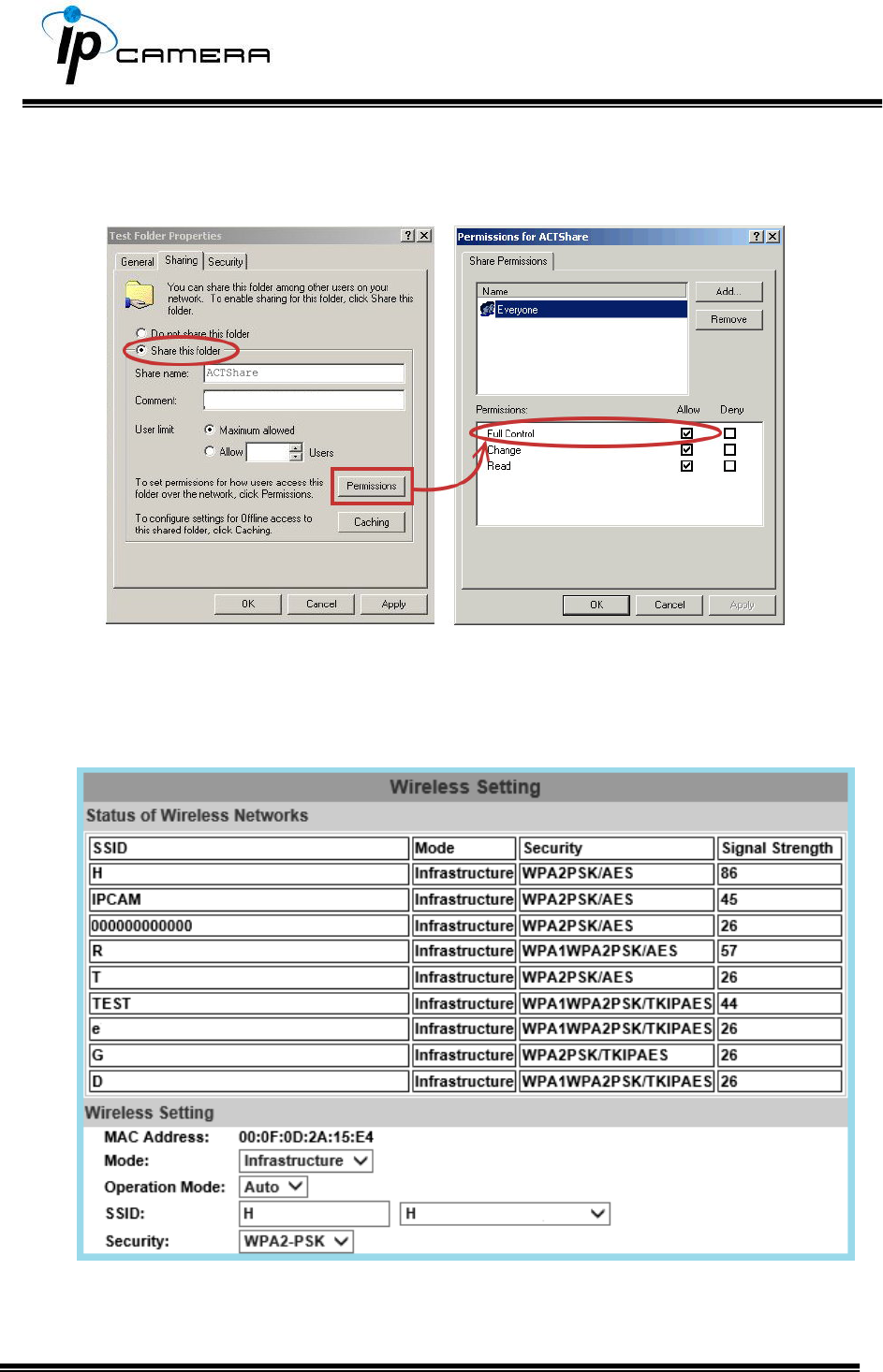
If the test failed, check the sharing setting of your location folder. The folder
properties must be shared and the permissions must be Full Control as the
picture.
V. Wireless Setting (Optional): Support 802.11 b/g/n
This function allows user to set up the IP camera wireless network connection.
a. Status of Wireless Networks
The camera scans and shows the SSID, Mode, Security, and Signal strength of
the wireless network.
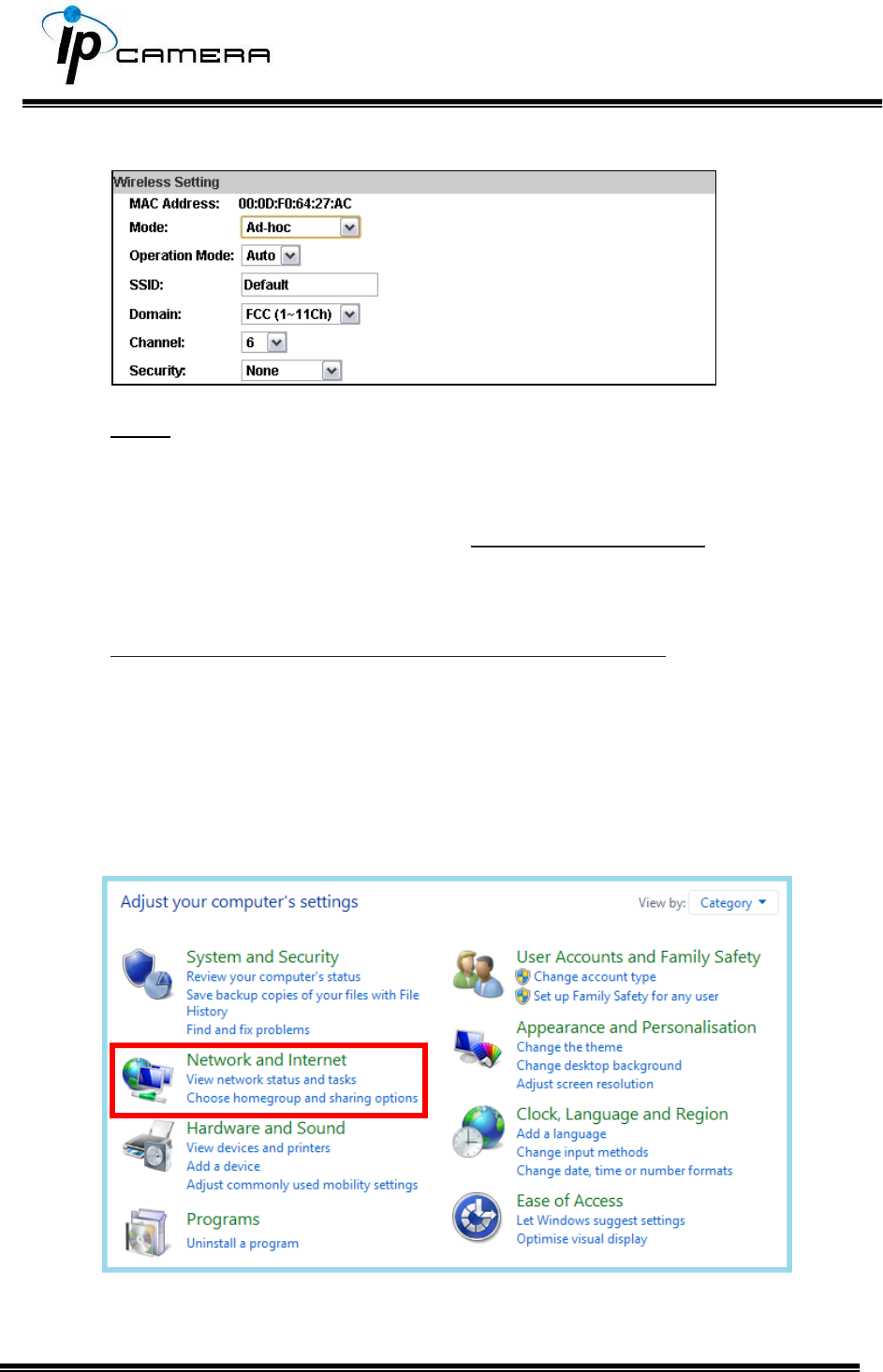
b. Wireless Setting
Mode: Infrastructure mode is used to link to the wireless router. Ad-hoc
mode is used to link to the PC directly.
Domain and Channel options appear only in the Ad-hoc mode.
Ad-hoc is a short term derived from wireless ad hoc network, known as
WANET. This type of network is only established temporarily, and does not
rely on a pre-existing network through a router or Wireless Access Point.
How to connect to an ad-hoc Wi-Fi network in Windows 8.1
To make the Ad-hoc mode available, follow the steps below. This is done
manually. Note that this demonstration applies to Windows 8.1 since the
Windows 8.1 system no longer shows Ad-hoc network in the Wi-Fi list.
The following example is based on another type of IP camera.
Go to “Control Panel”, then “Network and Internet”.
Click on "Network and Sharing Center".
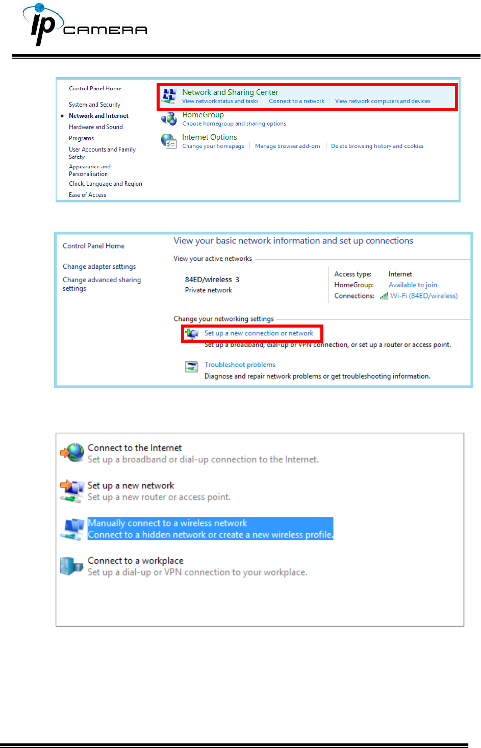
Click "Set up a new connection or network".
In the pop-up window, double click "Manually connect to a wireless network".
Enter the SSID of the ad-hoc network (as shown by "netsh wlan show
networks") into the "Network name" field.
Configure security settings accordingly.
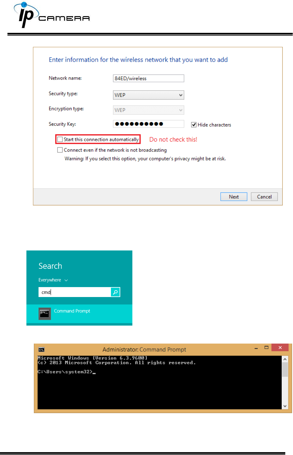
Make sure that "Start this connection automatically" is unchecked, click
"Next", then "Close"
Open the search window (Windows key+Q) and search for “cmd”
Run the command to open up a new window.
Enter the messages below.
1. > netsh wlan set profileparameter <ssid> connectiontype=ibss
2. > netsh wlan connect <ssid>
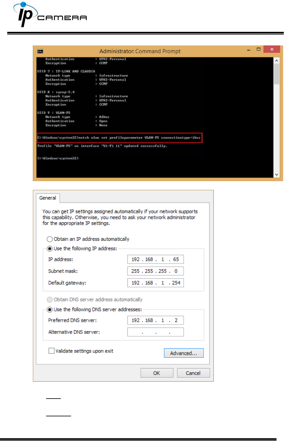
Now Ad-hoc mode is available after the IP settings completion.
SSID: The ID of the wireless network service.
Domain: The wireless network standards are different in each region.
Please select the wireless standard of you location. FCC is the American
standard. ETSI is the European standard. JP is the Japanese standard.
Channel: Assign a channel for the camera in order to avoid interference.
Security: Select WEP, WPA-PSK, or WPA2-PSK according to your wireless
router settings.
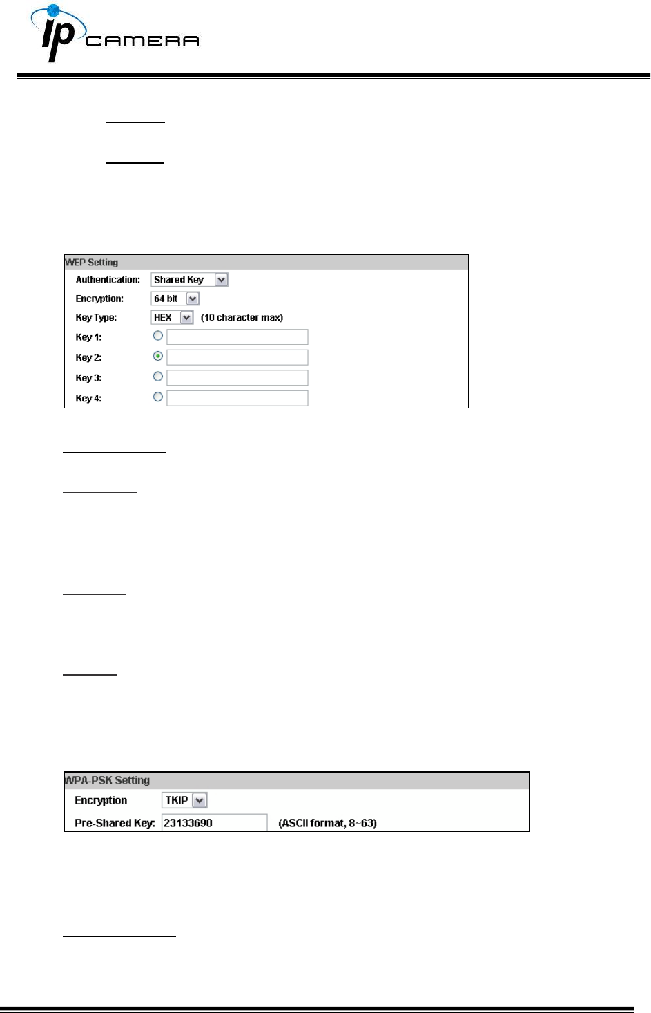
a. WEP Setting
Authentication: Open System or Shared Key, according to your wireless router.
Encryption: The option determines the length of the key password. In HEX type,
10 characters are allowed if you select 64 bit; 26 characters are allowed if you
select 128bit; In ASCII type, 5 characters are allowed if you select 64 bit; 13
characters are allowed if you select 128bit.
Key Type: In HEX type, the key password can only be hexadecimal numbers. In
ASCII type, the key password can be any letter and number. (Capital and
lowercase letters are regarded as different.)
Key 1~4: Enter the key password according to your wireless router setting. The
length and type must be consistent with the settings above.
b. WPA-PSK/ WPA2-PSK Setting
Encryption: TKIP or AES, according to your wireless router.
Pre-Shared Key: Key-in the key password according to your wireless router
settings. Any letters and numbers are allowed. (Capital and lowercase letters
are regarded as different.)
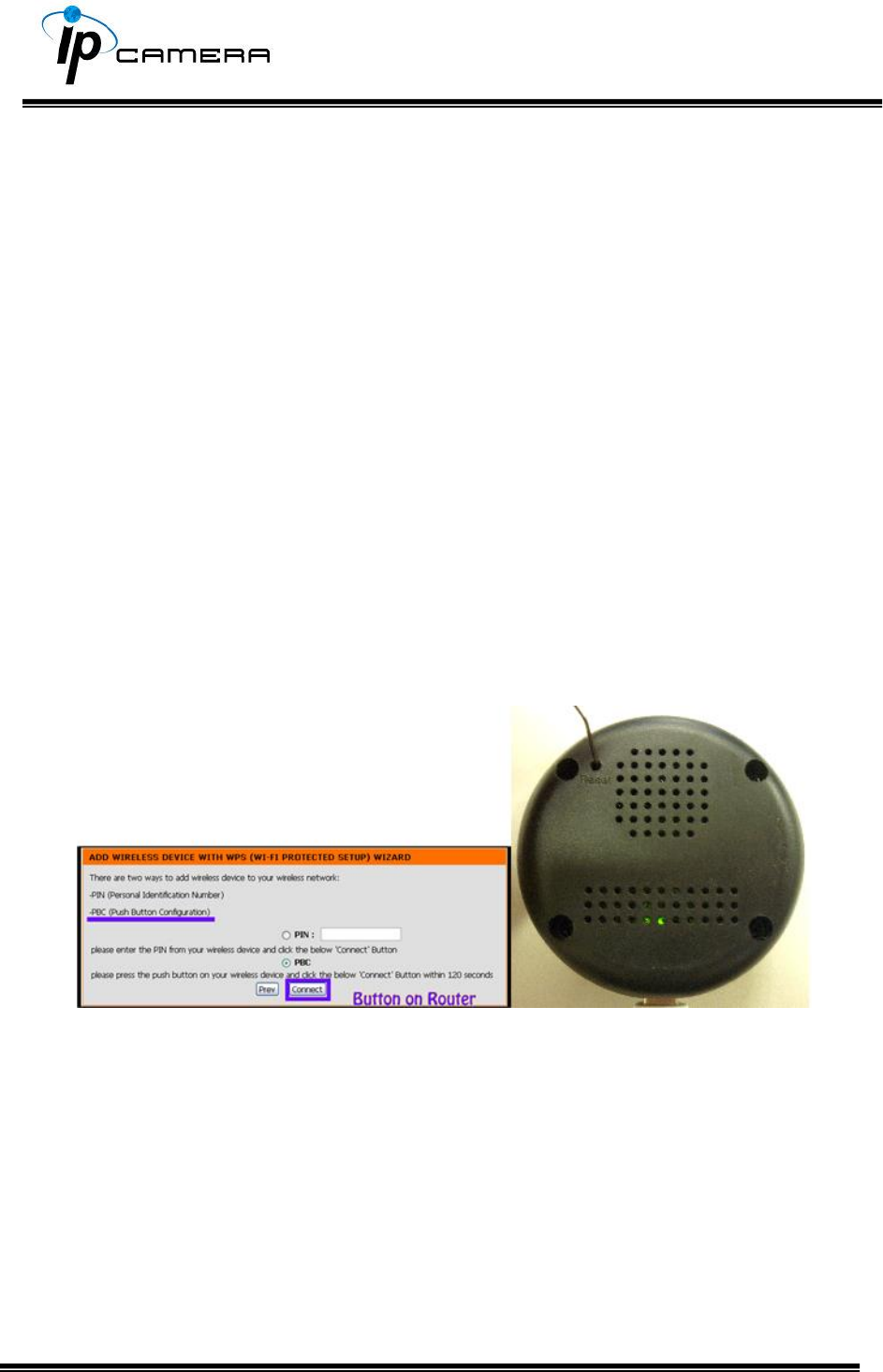
c. WPS
WPS (Wi-Fi Protected Setup) is an interface standard that allows users to
easily establish wireless network, and be free from complicated security
setting.
Please follow the steps for starting WPS. The menu and usage of every
router may be different from the sample pictures.
Set up SSID and pre-shared key on your wireless router. WPS only supports
WPA/WPA2 security. Do not select WEP security. Plug on the power adapter to
the IP camera.
Once the wireless connection of the camera has been established with the PC,
enter the wireless setting page, and check if the SSID of your wireless router is
listed in Status of Wireless Networks. If yes, continue toward next step, no
other wireless settings are needed.
Access your router, and press the Connect button of the PBC (Push Button
Configuration) setting page on your router. Then use any hard & tiny little stick
to reach the WPS button within the hole where there is a word “Reset” right
under. The green light inside the camera at the back will start flashing.
When it finally stops flashing and lights constantly, it means the WPS
connection is successful. Refresh the wireless setting page on the camera; you
will see that the security settings have been already automatically completed.
Meanwhile you might see a message on your router page to inform you the
connection is OK.
If the light finally stops flashing but the lights are off, it means the WPS
connection failed.
Check your wireless router setting, and make sure the SSID of the wireless
router is found by the camera and listed in Status of Wireless Networks.
A / V Settings
Click to get into the administration page. Click to go back to the live
video page.
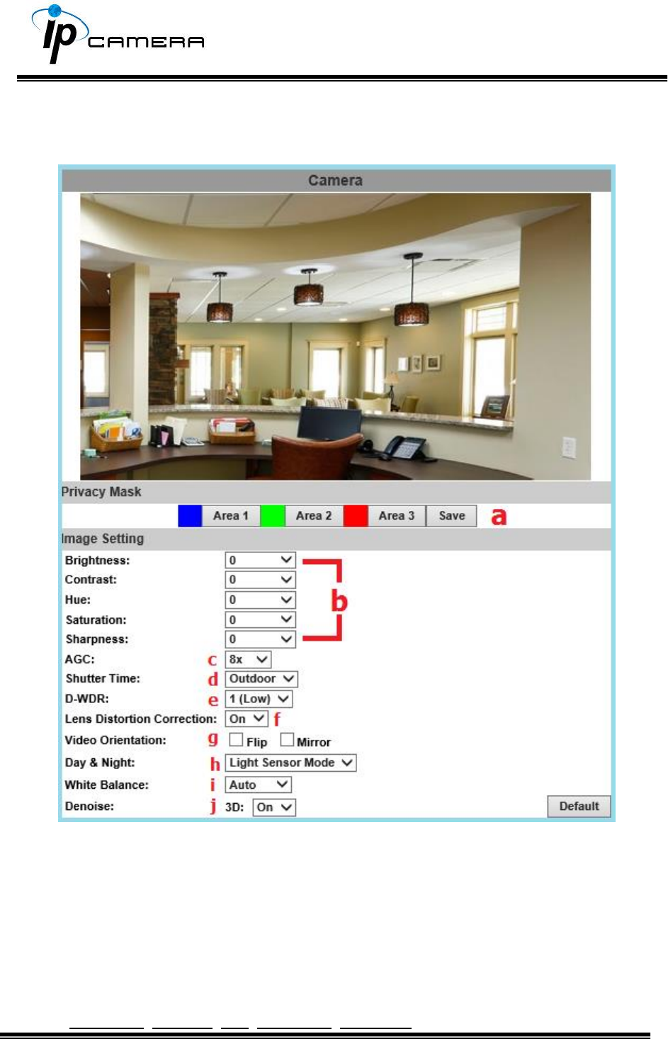
1. Image Setting
Please refer to the details below for image settings:
a. For security and privacy purposes, there are three areas that can be set
up for privacy. Click the Area button first, and then drag an area on the
above image. Remember to save your settings. The masked area will not
be shown on both live view and recording image.
b. Brightness, Contrast, Hue, Saturation, Sharpness can be adjusted here.

c. AGC: The sensitivity of the camera can be adjusted to the environmental
lighting. By enabling this function the camera will get brighter images on
low light, but the level of noise may also increase. The available values are:
16x, 24x, 32x, 48x.
d. Shutter Time: Choose the location of your camera or a fixed shutter time.
The shorter the shutter time is the less light the camera receives and the
image becomes darker.
Note: When you select a number in Shutter Time, the shutter time will vary in a
range and be controlled by camera automatically. The following table shows the
shutter time options and corresponding range.
e. D-WDR: This function enables the camera to reduce the contrast in the view
to avoid dark zones as a result of over and under exposure. If the Input
resolution is 30fps, the default value is fixed on ENABLED. The available values
are: OFF, 1, 2, 3, 4, 5, 6, 7, 8
If the D-WDR is enabled the values for bright, dark and contrast can be
adjusted.
f. Lens Distortion Correction: Straight the curves in the borders of the image
caused by the lens angles. The available values are: OFF, 1, 2, 3, 4, 5, 6, 7, 8, 9,
10.
g. Video Orientation: Flip or mirror the image.
h. Day & Night: The camera can detect the light level of the environment. If you
choose Light Sensor Mode, the image will be turned black and white at night
in order to keep a clear image. Under Times Mode the switch time of
Color/Black and white will be according to the given time. You can also control
it by choosing Color or B/W.
i. White Balance: There are 6 modes which can be assigned for different
lighting sources:
AUTO - Continuously adjusts camera color balance according to any change of
color temperatures and lightings.
Manual –Adjust color balance with Red Gain & Blue Gain values.
j. Denoise: This function is able to filter the noise and blur from the image and
show a clearer view. You can set the values for 3D filters.
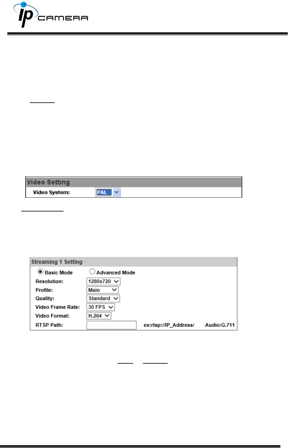
2. Video Setting
Video System: NTSC or PAL
The IP Camera provides three types of streaming settings:
a. Streaming 1 & 2 Basic Mode:
1. 1920x1080@30fps,1280x720@30fps, 640x480@30fps, 320x240@30fps
2. Profile: Chose between Main or Baseline
3. Quality: There are 5 levels. Best/ High/ Standard/ Medium/ Low
The higher the quality is, the bigger the file size becomes. Not good for Internet
transmission.
4. Video Frame Rate (5~30 FPS): The video refreshing rate per second.
5. Video Format: H.264 or JPEG
6. RTSP Path: RTSP output name
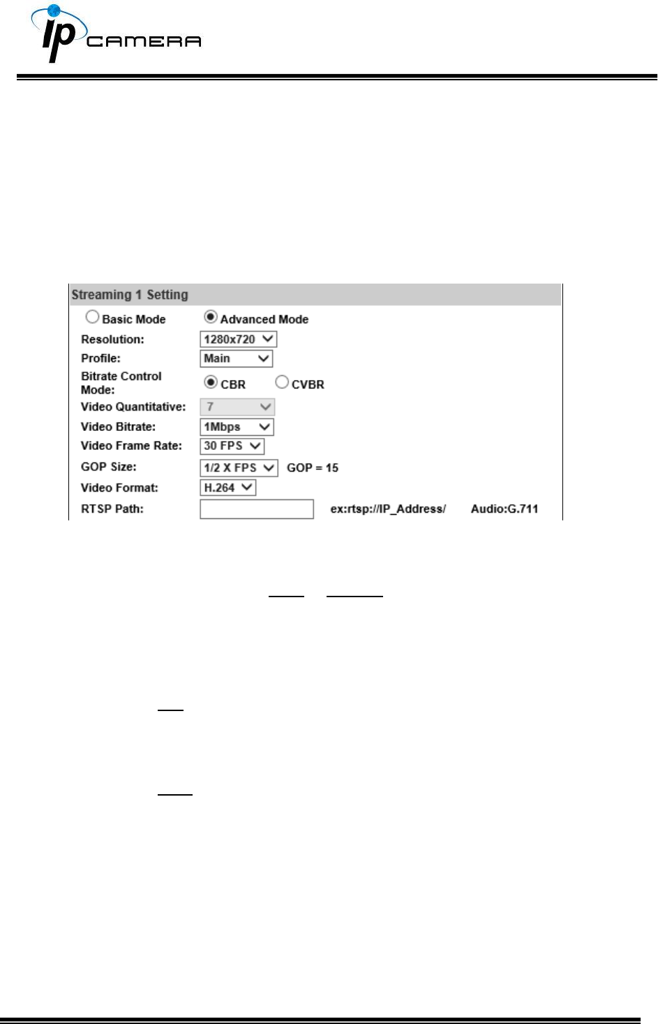
b. Streaming 1 & 2 Advanced Mode:
1. 1920x1080@30fps,1280x720@30fps, 640x480@30fps, 320x240@30fps
2. Profile: Chose between Main or Baseline
3. Bitrate Control Mode: There are CBR (Constant Bit Rate) and CVBR
(Constrained Variable Bit Rate)
CBR
Video Bitrate Limit: (32Kbps~8Mbps)
The higher the CBR is, the better the video quality is.
CVBR
Video Quantitative: 1(Low) ~10(High)
The higher the compression rate, the lower the picture quality is; vice versa. Avoid
image breaking up or lagging by setting the bandwidth limit for CVBR streaming.
4. Video Frame Rate (5~30 FPS): The video refreshing rate per second.
5. GOP Size (1, 1/2, 2) X FPS: "Group of Pictures". The higher the GOP is,
the better the quality is.
6. Video Format: H.264 or JPEG
7. RTSP Path: RTSP output connecting path
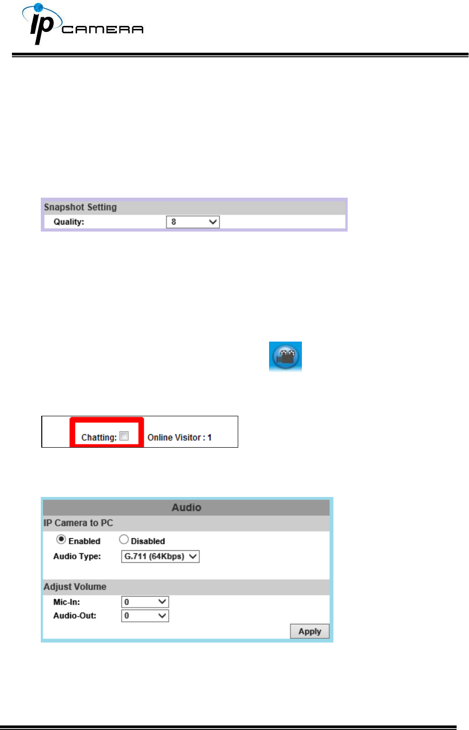
c. Snapshot Setting:
Select the snapshot image quality from 1(Low) ~10(High).
3. Audio
The IP Camera supports 2-way audio. The user can send audio from the IP
Camera built-in microphone to the remote PC; the user can also send audio
from remote PC to IP Camera’s external speaker.
a. Audio from local PC to IP Camera: Click on the icon and mark “chatting”
in the Live View browser page. Note that the audio will not be smooth when the
SD card is being recorded.
b. IP Camera to PC (Audio from IP camera built-in microphone to local PC): Select
Enable to start this function & you also can select the audio type.
c. Adjust Volume: When both Chatting (in live mode) and Audio Out are on, the
built-in microphone may be automatically shut down to avoid echoing effects.
Event List
Click to get into the administration page. Click to go back to the live
video page.
The IP Camera provides multiple event settings.
1. Event Setting
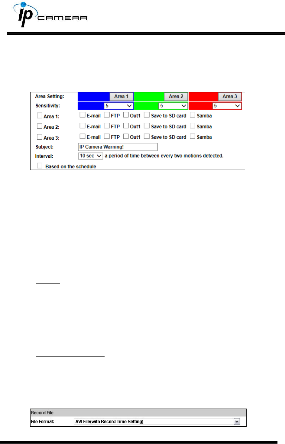
a. Motion Detection
To enable motion detection, tick Area 1/2/3. Click Area 1/2/3 in Area Setting,
and draw an area on the preview screen. When motion is detected in the area,
the word Motion! will be displayed on the live screen. The camera will send
video or snapshot to specific mail addresses, trigger the output device, or save
video to FTP/ Micro SD card/ Samba.
By selecting save to SD card, the video or snapshot will be saved to the Micro
SD card. Also, by ticking E-mail/ FTP/ Samba on the Log option, the motion
detection log will be sent to E-mail/ FTP/ Samba simultaneously.
Subject: Type in the message you would receive when motion is
detected. The default message is “IP Camera Warning!”.
Interval: For example, when selecting 10 sec, once the motion is
detected and the action is triggered, it cannot be triggered again
within 10 seconds.
Based on the schedule: When the option box is ticked, only during the
selected schedule time the motion detection is enabled.
b. Record File
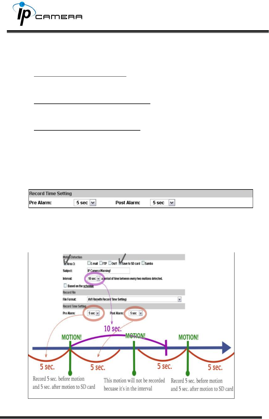
When an event occurs, the IP camera will record a video clip or take snapshot,
and then send to mail/ FTP/ Samba. Select the file format to be saved.
AVI File (with Record Time Setting): Save AVI video file. The video length is
according to the value set in Record Time Setting.
JPEG File (Single File with Interval Setting): Save single JPEG picture file
when the event occurs.
JPEG Files (with Record Time Setting): Only when selecting "JPEG" in
streaming 1 video format of Video Setting, this option can be enabled. Select
this option to save several JPEG picture files. The successive picture files
cover a period of time according to the value set in Record Time Setting.
c. Record Time Setting
When an event occurs, the IP camera can record a video clip or take a
snapshot, and then send it via mail/ FTP/ Samba. Select the video recording
length before and after the event is detected.
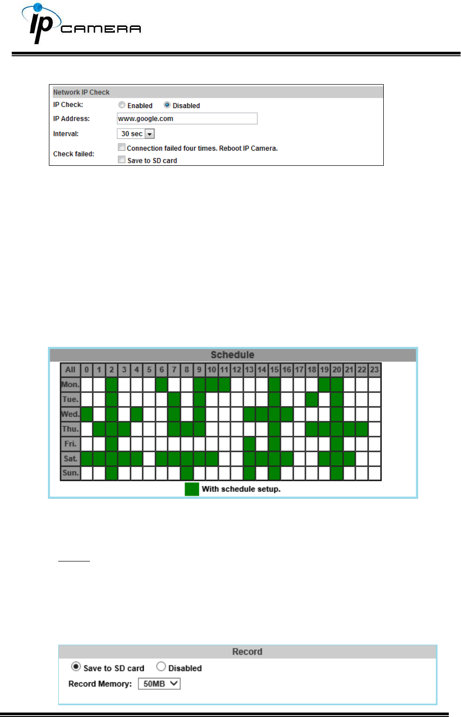
d. Network IP Check:
After enabling IP Check, the IP camera can check if the network server is
connecting. If the IP camera checking failed, the image will be recorded to the
SD card.
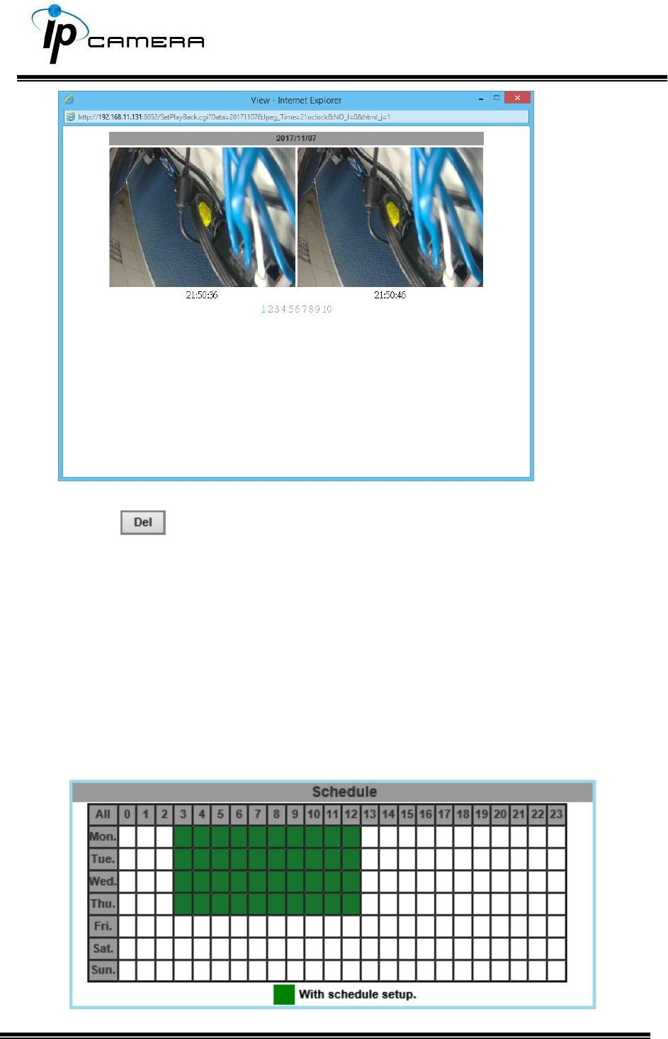
2. Schedule
a. Schedule: Tick the grids on the calendar to manage the time of your schedule
to automatically record video files, or take snapshots.
b. Snapshot & Record:
Record: After completing the Schedule, the camera data will be recorded according
to the schedule made from the calendar. Be aware that SD cards may fail in time
for being recorded too long.
You may set up how much you would like the SD card memory to be used in order to
estimate when it is a right time to swap for a new one.
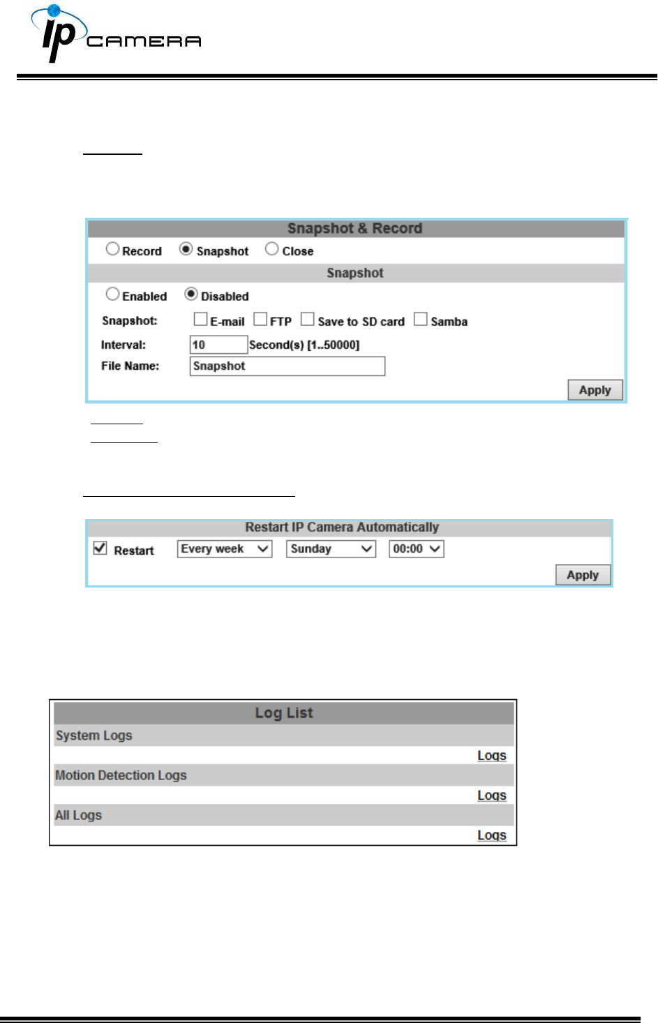
Snapshot: After enabling the snapshot function; the user can select the storage
position of the snapshot file, the interval time of the snapshot and the reserved
file name of the snapshot.
Interval: Users can set the interval between two snapshots.
File Name: Enter the file name of your snapshot file.
Restart IP Camera Automatically: Set up the time for IP camera to restart
automatically after ticking Restart to enable access.
3. Log List
Sort by System Logs and Motion Detection Logs. In addition, System Logs won’t
lose data due to power failure.
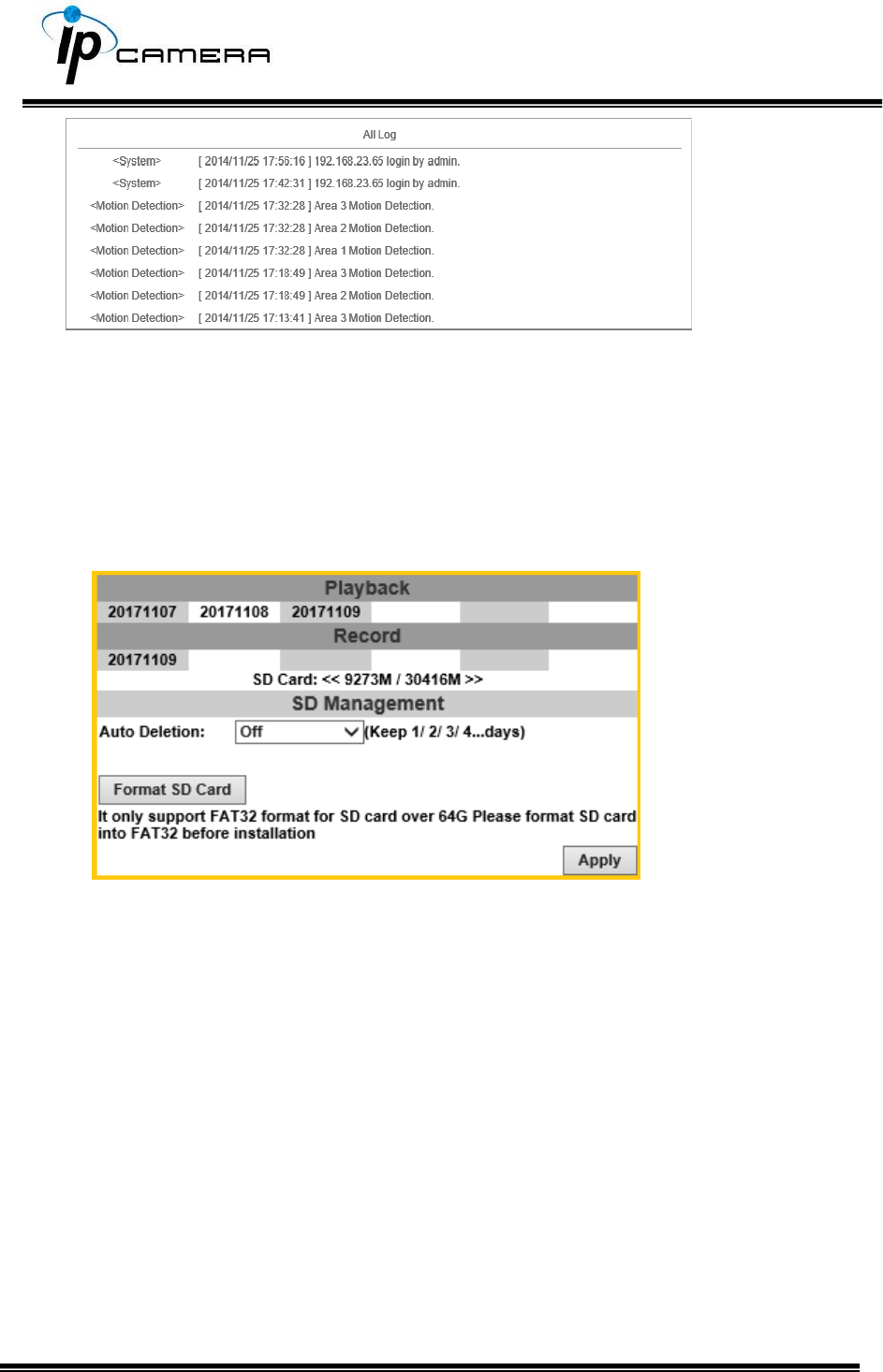
4. SD Card
Please Insert t h e Micro SD card before use it. Make sure t o push the Micro
SD card into the slot completely.
a. Playback
Click the date under the Playback title and a list of files will pop up.
For example, if the date 2017/11/07 is clicked, all the events happened within
that time frame will then appear in a list like the one below.
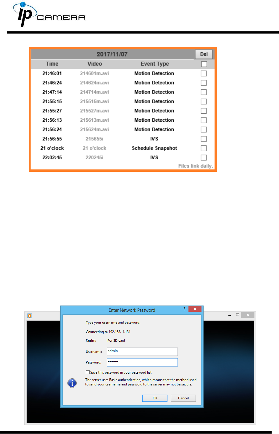
The enlisted files under Video category are files representing events.
There are 3 types of file formats, and each is different for its own Event Type.
Notice how the file name formations under the Video category represent the
time when a file is created. For instance, the file name “214601m.avi” means
the video is recorded at 21:46:01 today, m means Motion Detection, and avi
represents the file format.
Click on the file name to open the file.
For avi files, you need Microsoft Media Player which is supposedly
built-in in your PC. The default Username & Password for playing the video
file are both admin.
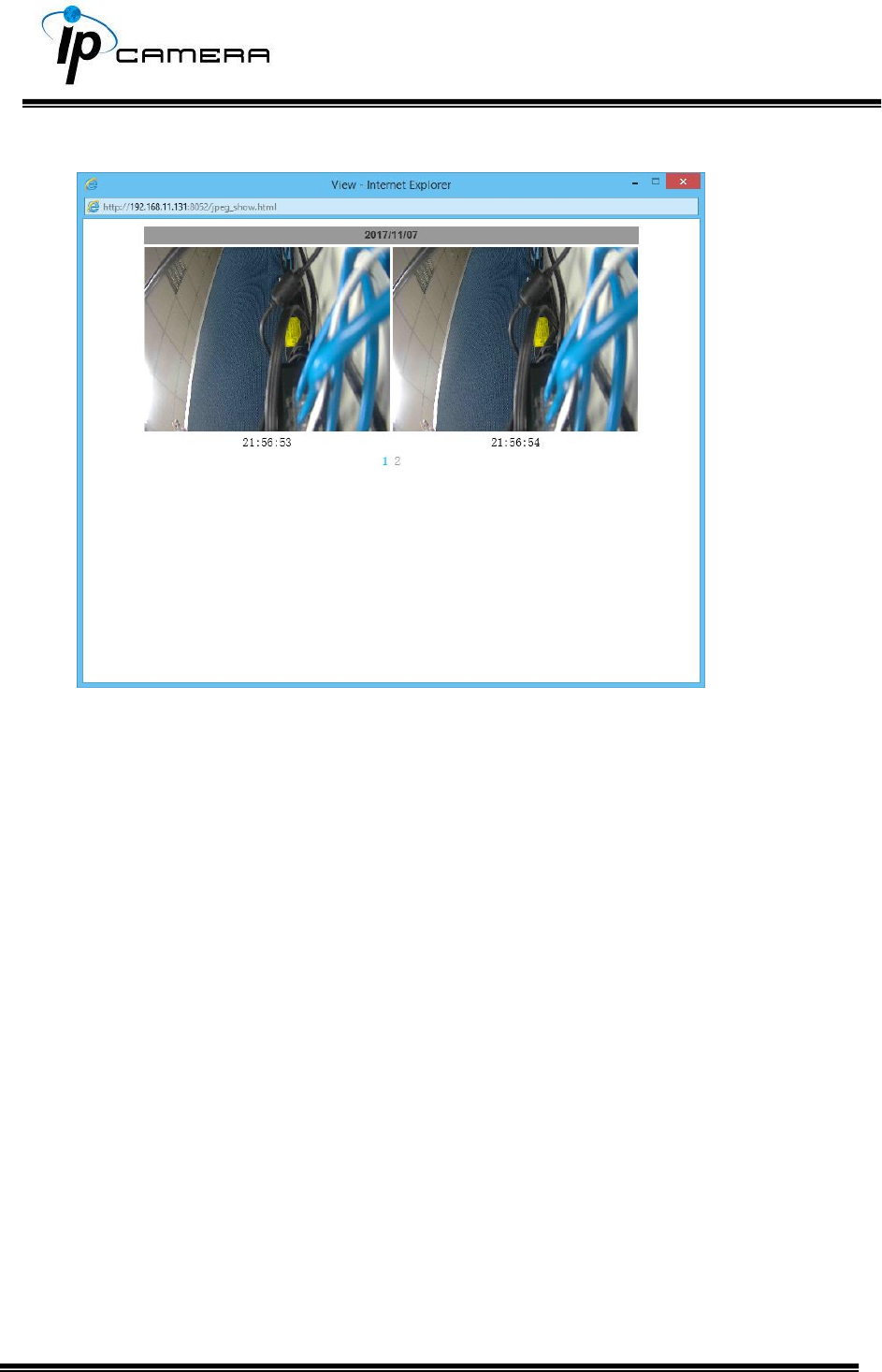
Clicking on an IVS file (such as 215655i) will bring out a pop-up window
suggesting an IVS event captured as snapshots as the one below:
Clicking on any title that is labeled with “time unit” (such as 21 o’clock) at the
end will bring out a pop-up window indicating the snapshot taken as scheduled
in Schedule mode and enabled in Snapshot mode.
Click the icon to delete any file by marking on the checkbox under the Del
category with a mouse click.
b. Record
The recording mode is enabled after Record is set in Schedule mode.
Take the schedule calendar below for example, the grids coloured in green
between 3~12 are scheduled to start recording from 3 o’clock to 12 o’clock
from Monday to Thursday.
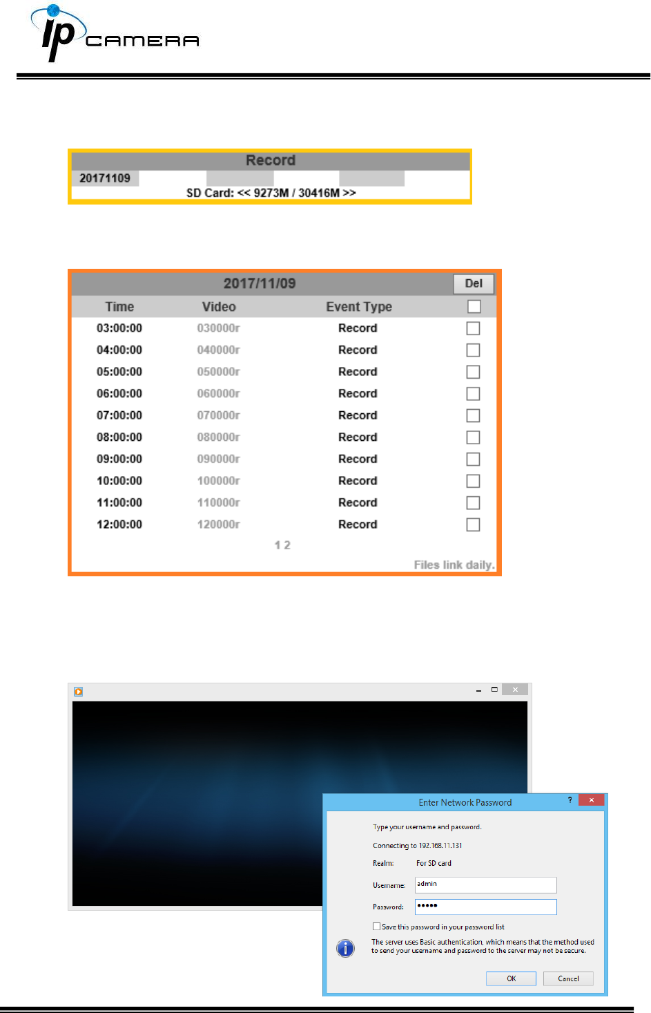
Once the recording mode is on, the video data recorded will be found and
labelled as 2017/11/09.
Click on 2017/11/09 to enter the next page where all files recorded on that
date are enlisted.
Click on any video title to open Microsoft Media Player (supposedly
already built-in in your PC) and play the video file. Key-in admin for
both Username & Password to get permission to view the video.
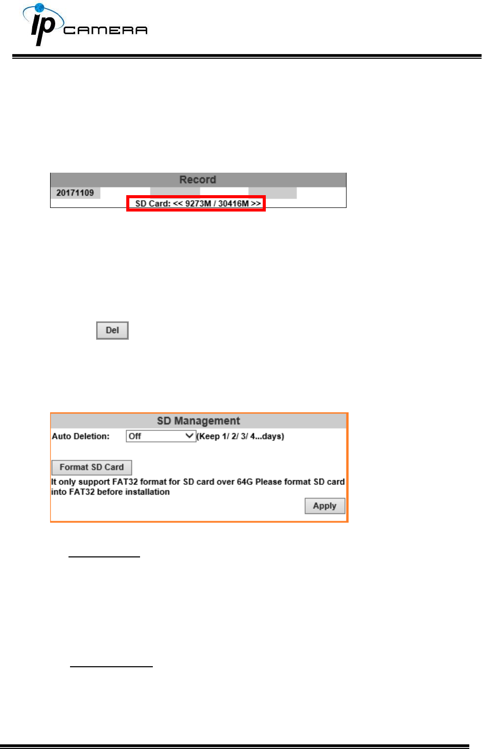
The number at the bottom indicates the distributive law of the current SD
Card memory which is divided and assigned to different types of recording
purposes. The left side shows how much memory is still available, and the
right side shows how much the total memory is.
If the memory of the SD card is over 128G, 70% of the memory will be used
for scheduled recording, and 30% will be used for event recording.
If the memory of the SD card is below 128G, 50% of the memory will be used
for scheduled recording, and 50% will be used for event recording.
Click the icon to delete any file by marking on the checkbox under the
Del category with a mouse click.
c. SD Management
c1. Auto Deletion: Choosing “The 1st day” means the recoding file will be kept
for one day. Example: It is five o’clock now. Choose “The 1st day”. The files will be
kept from five o’clock yesterday to five o’clock today. The oldest file will be deleted if
the Micro SD card is full.
Note:The use of the SD card will s l i g h t l y affect the operation of the IP
Camera, such as affecting the frame rate of the video.
c2. Format SD Card: Click the icon to process the SD Card formatting into
FAT32 format. Be cautious that since it only supports FAT format for SD Card
over 64G, please format SD Card into FAT32 before installation.
d. SD Card Files
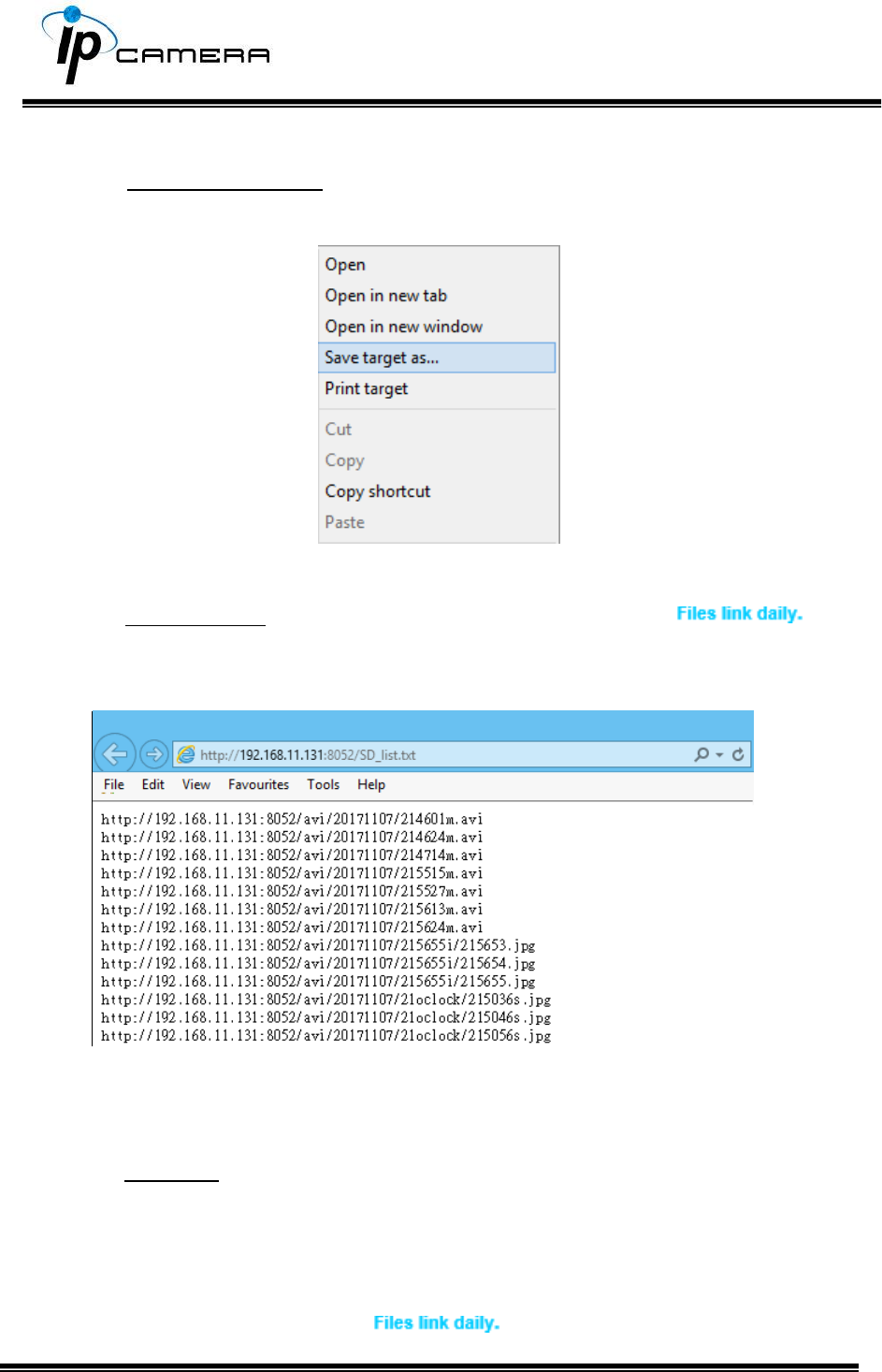
d1. Downloading the Files: For both Playback and Record mode, after entering a
date data to see the Video and Event Type, right-click on a title under the Video list,
and choose “Save Target As…” from its pop-up window to start downloading the file.
d2. Linking the Files: For both Playback and Record mode, find the
link at the right corner of the bottom after entering a date data to see the Video and
Event Type. Click on the link, a window will pop up.
You may copy any of the protocol provided in the window and paste it on a web
browser as a URL address to look at each file.
d3. Copy to PC: You can insert the Micro SD card to the PC and read the files directly,
or use FlashGet instead to download the files from the IP camera. (In this way you do
not need to pull out the Micro SD card from the camera.) To use FlashGet for
downloading image and video data from the Micro SD card, please follow the
steps:
i. Enter data list and right-click “ ”, select “save target as…” then save
the link list to PC.
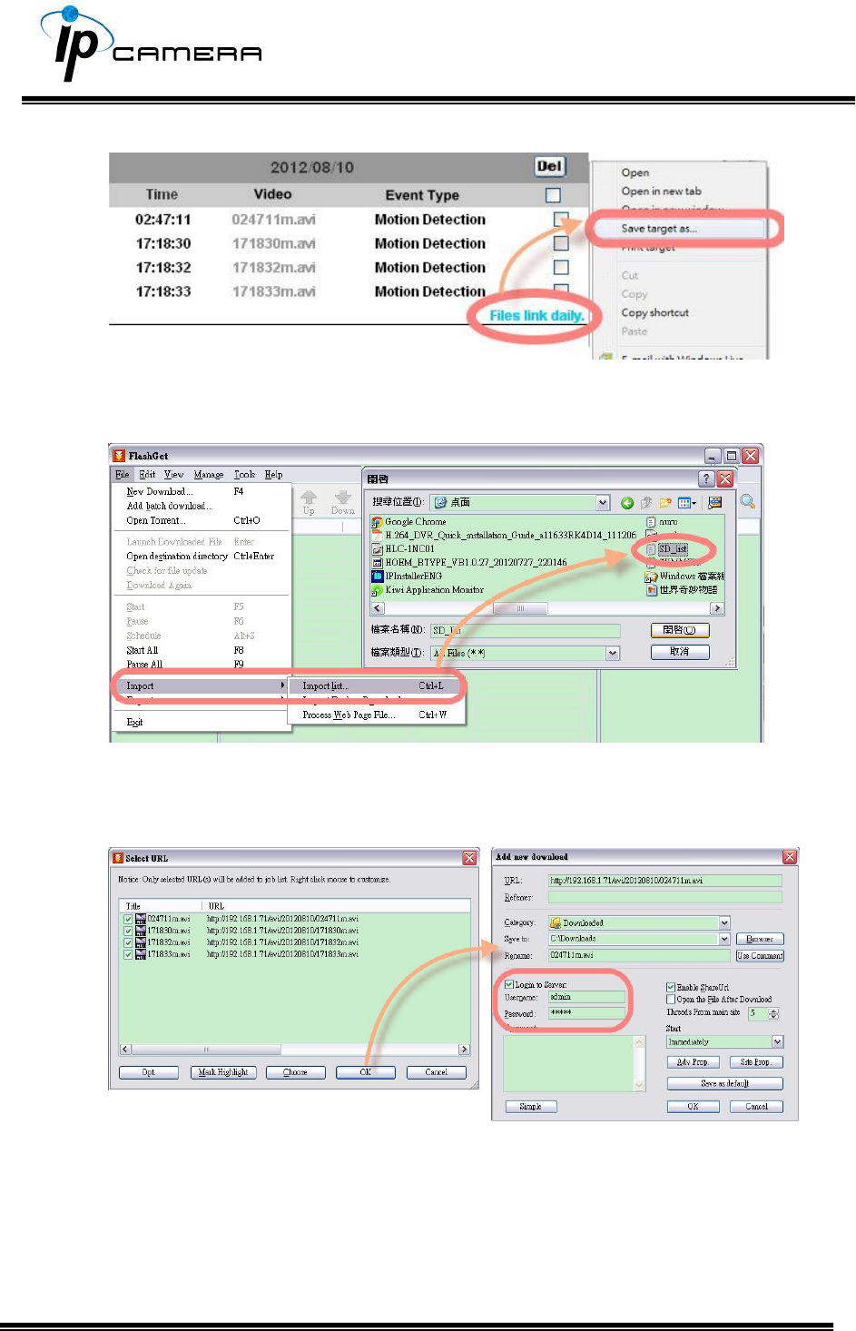
ii. Open FlashGet, select "File"→ "Import" → "Import list", and find the link list file
you just saved. The file name may be called “SD_list”.
iii. FlashGet will show you the link list, and you can tick the files you want to copy to
your PC. Give the directory path in the new download window, and remember to
enable "Login to Server": key in the IP Camera username and password.
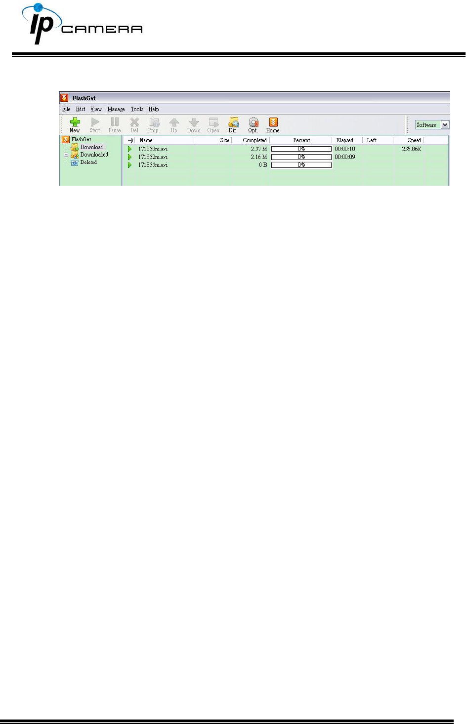
iv. Click OK to start download.
FlashGet is free software that can be downloaded from FlashGet official
website. The example above is based on FlashGet ver.1.9.6.
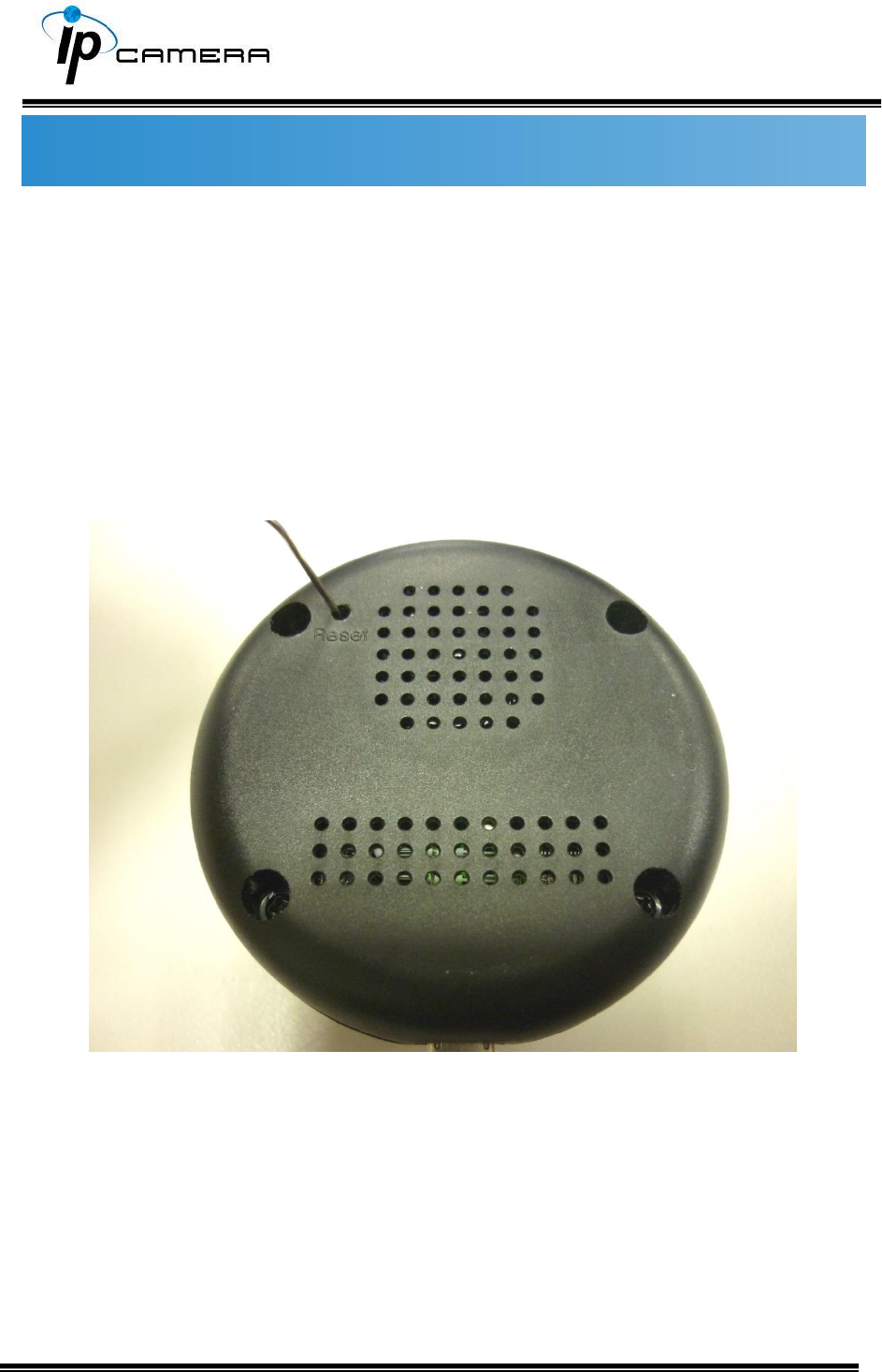
Factory Default
If you forget your password, please follow the steps to set back the IP Camera
to its default value.
• Keep the power through while it is already switched on.
• Use any hard & tiny little stick to reach into the hole where there is a
word “Reset” right under. Press and hold the button within as
demonstrated in the picture below.
• It will take around 5 seconds to boot the camera.
• Release the button when the camera finishes booting.
• Re-login the camera using the default IP (http://192.168.1.200), and user
name: admin, password: admin.
Universal Password
If you forgot the password of your IP camera, you can reset the camera to factory
default, or follow the procedure below to generate a universal password.
Note: Universal password will be valid only when you enable the function in User
Management.
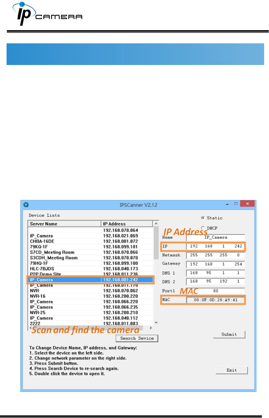
1. First, you need to know the IP address and MAC address of your IP camera.
You can use IP Scanner to scan the LAN, and see the IP address and MAC
address on the side column.
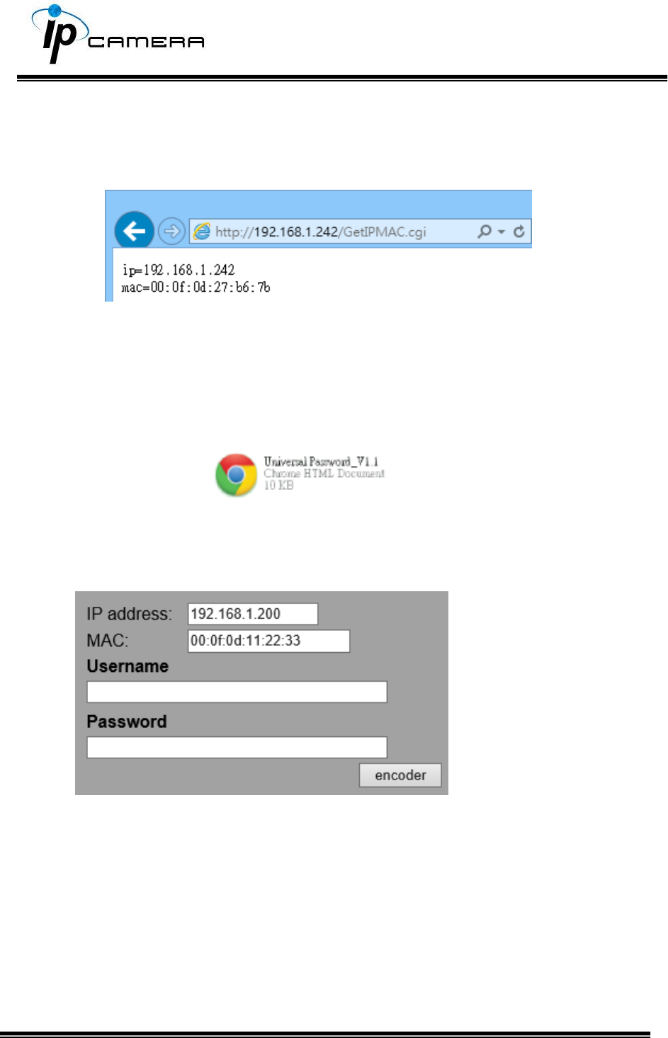
Or, if you already know the IP address of camera: Open the web browser, key in
http:// (IP address) /GetIPMAC.cgi and press enter. The IP address and MAC
address will be displayed on browser.
2. Locate the .html file named Universal Password_V1.1 in the Universal
Password from the Applications folders in CD-ROM. Open it with a web
browser.
3. The camera IP address and MAC address will be displayed automatically in
both IP Address and MAC columns.
After clicking on encoder, a set of username and password will appear.
The universal username and password are generated from the IP address and
MAC address you key-in, so if you change the camera IP address the universal
password changes, too.
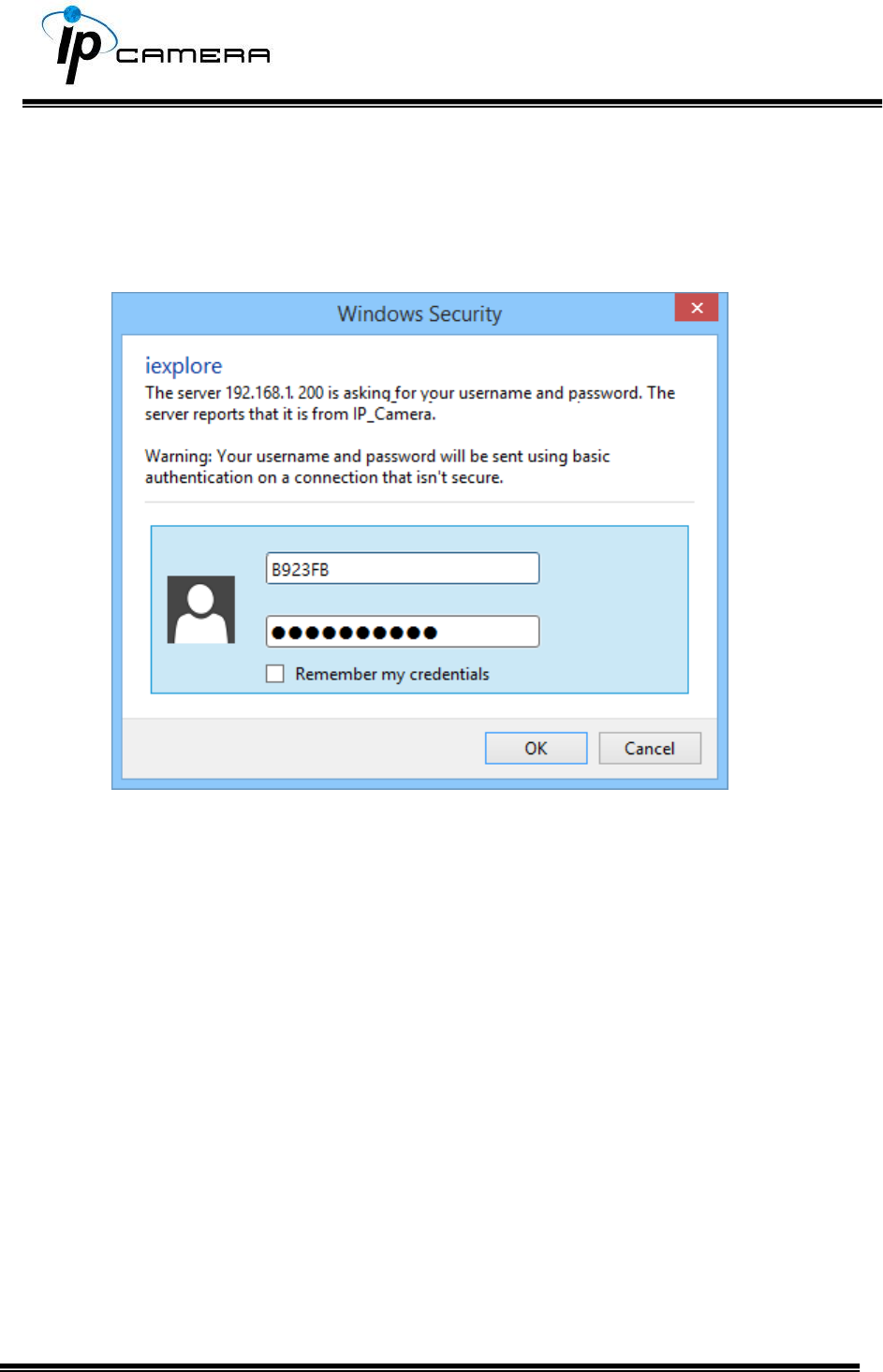
4. Take the generated username and password. Use them to log into the
camera.
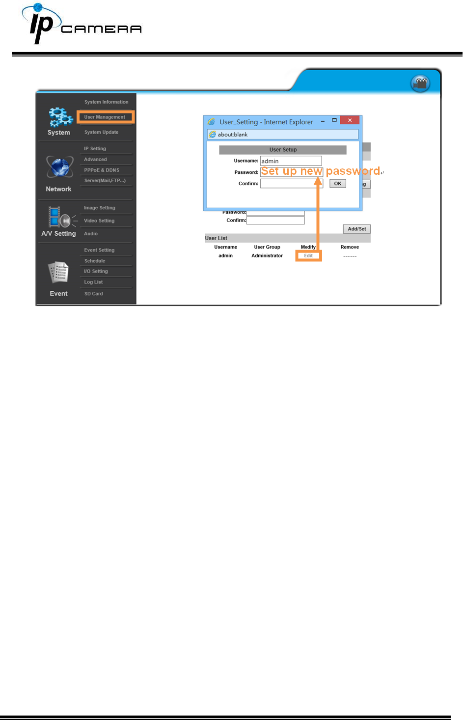
5. Now you can login as administrator. Turn to User Management page. The use
of universal password does not affect the previous user setting, so the
administrator account password does not change until you edit it. Please click
Edit to give a new administrator password.
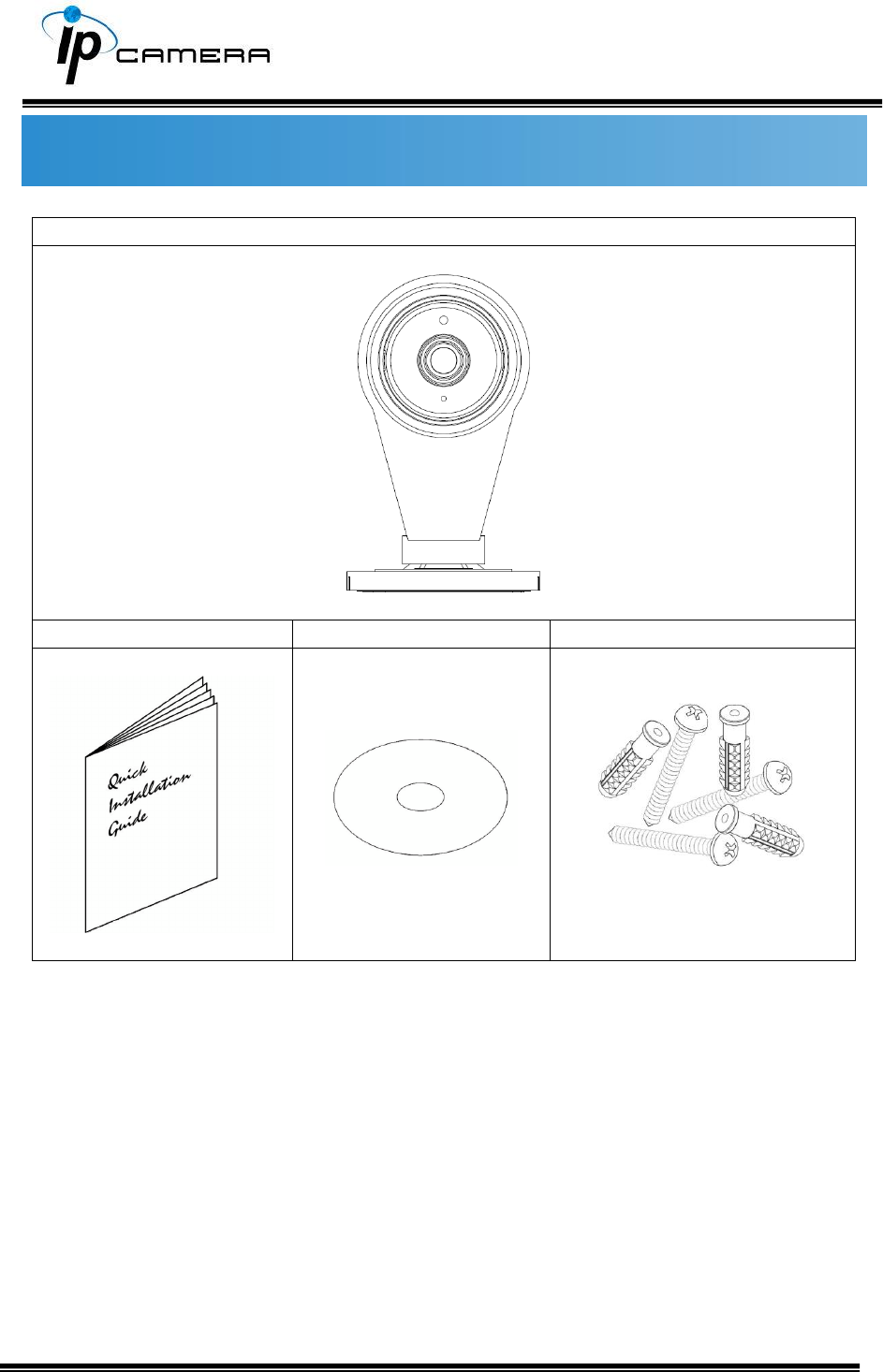
Package Contents
IP Camera
Quick Installation Guide
CD
Screw Package
• The CD includes user manual and software tools

Micro SD Card Compatibility (Optional)
The following are the recommended Micro SD Cards:
Transcend
SDHC class4 16GB
SD class4 16GB
SDHC class4 32GB
SD class4 32GB
SD class6 4GB
SDHC class6 4GB
SD class6 8GB
SDHC class6 8GB
SD class6 16GB
SDHC class6 16GB
SDHC class10 4GB
SDHC class10 8GB
SDHC class10 16GB
SDHC class 10 Max. 64GB
SanDisk
SDHC class4 8GB
SDHC class4 16GB
SDHC class4 32GB
SDHC class10 Max. 128GB