Hunter Douglas Window Fashions ROL Motor Control User Manual
Hunter Douglas Window Fashions Motor Control Users Manual
Users Manual
Installation • Operation • Care
Sonnette™
Cellular Roller Shades
PowerView™ Motorization

CONTENTS
Questions?
Call Hunter Douglas Consumer Support at 1-888-501-8364.
© 2016 Hunter Douglas. All rights reserved. All trademarks used herein are the property of Hunter Douglas.
or their respective owners
Getting Started:
Product View ........................................................................................................1
Tools and Fasteners Needed ..................................................................................2
Installation:
Installation Overview .............................................................................................3
STEP 1 — Mount the Installation Brackets .............................................................3
Inside Mount .....................................................................................................4
Outside Mount ..................................................................................................6
STEP 2 — Install the Shade ..................................................................................8
STEP 3 — Connect the Power Source ....................................................................9
Attach the Magnetic Hold-Down Brackets (Optional) ..............................................14
Operation:
Testing the Shade ...............................................................................................15
Using the PowerView™ Remote ............................................................................15
Resetting the Shade (If Necessary) .......................................................................17
Troubleshooting ..................................................................................................18
Care:
Removing the Shade ...........................................................................................26
Cleaning Procedures ...........................................................................................26
Declarations ......................................................................................................27
Warranty ................................................................................................ Back Cover
GETTING STARTED
1
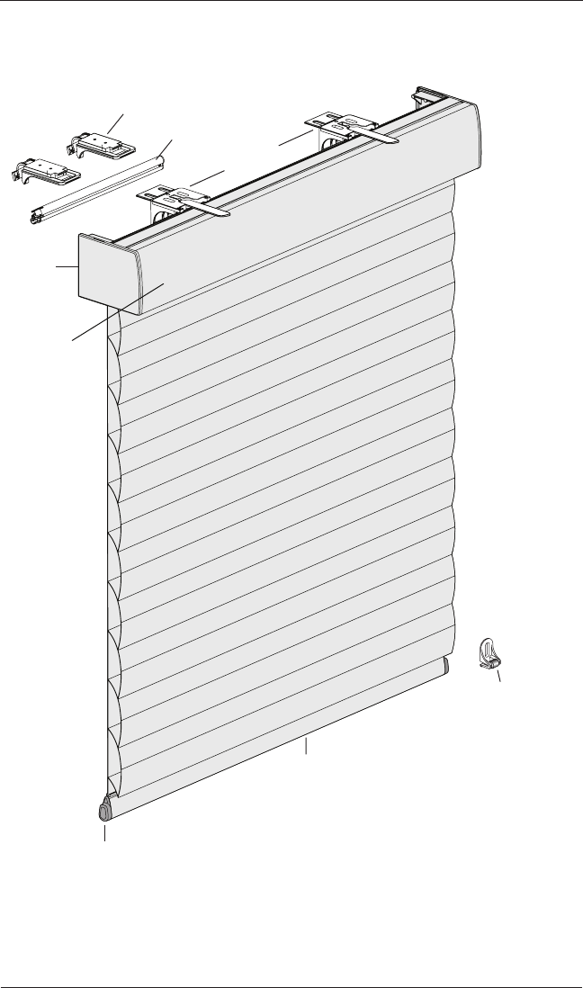
Product View
Installation
Brackets
End
Cap
Bottom Rail
End Cap
Magnetic
Hold-Down
Bracket
(Optional)
Headrail
Bottom Rail
Battery Wand
Battery Wand Clips
2
GETTING STARTED
Thank you for purchasing Hunter Douglas Sonnette™ Cellular Roller Shades. With proper
installation, operation, and care, your new shades will provide years of beauty and performance.
Please thoroughly review this instruction booklet and packing list before beginning the
installation.
Tools and Fasteners Needed
■Flat blade and Phillips screwdrivers
■Level (laser level is recommended)
■Measuring tape and pencil
■Pliers
■Power drill,
3
/
32
" drill bit, and
1
/
4
" hex driver
■Scissors (heavy-duty)
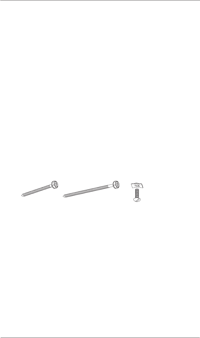
In addition, you will need fasteners designed to work with your specific mounting surface(s).
■#6 Hex Head Screws (Provided). Two 1
1
/
2
" screws are provided per installation bracket.
■Longer #6 Hex Head Screws (Not Provided). If using spacer blocks, use #6 screws long
enough for a secure attachment.
■Speed Nuts and Screws (Provided). Extension brackets come with screws and speed nuts.
■Drywall Anchors (Not Provided). Use drywall anchors when mounting into drywall.
Speed Nut
and Screw
(Provided with Each
Extension Bracket)
#6 x 1
1
/
2
"
Hex Head Screw
(Provided)
Longer #6 Hex Head Screw
for Use with Spacer Blocks
(Not Provided)
INSTALLATION
3
Installation Overview
To install your shade, you will need to perform the following three steps:
STEP 1: Mount the Installation Brackets
STEP 2: Install the Shade
STEP 3: Connect the Power Source
STEP 1 — Mount the Installation Brackets
■Your order will include the correct number of installation brackets for your shade width, as
shown in the table below.
■Shade orders may also include spacer blocks or extension brackets, if they were specified
for added clearance.
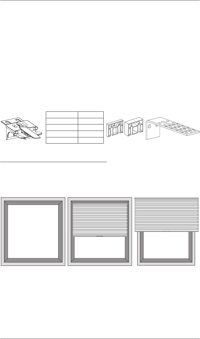
Mounting Types and Window Terminology
If the installation brackets are mounted correctly, the rest of the installation process follows
easily. To prepare for this important first step, review the mounting types and basic window
terminology illustrated below.
■Refer to the appropriate page below based on your order:
➤Inside Mount — Page 4
➤Outside Mount — Page 6
Installation Bracket For Added Clearance
Shading Width Brackets
2
3
4
5Extension
Bracket
1
/
4
" or
1
/
2
"
Spacer Blocks
14" – 36"
36
1
/
8
" – 79"
79
1
/
8
" – 96"
96
1
/
8
" – 120"
Outside Mount
Shading mounts
outside window
opening.
Inside Mount
Shading fits within
window opening.
Collectively, the sill and
jambs are called the
“window casement.”
Molding
Head Jamb
Sill
Jamb Jamb
INSTALLATION
4
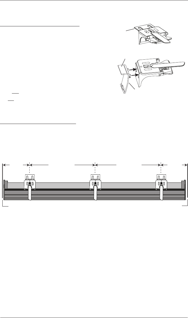
Mount the Installation Brackets — Inside Mount
Prepare the Installation Brackets
■If using the optional back cover: Use pliers or
heavy duty scissors to remove the top tabs on the
installation brackets.
➤Then remove the top tab on the back cover
brackets.
➤Snap the prongs on the back cover brackets into
the holes on the back of the installation brackets.
■If not using the optional back cover: Remove the
top tab only on the installation brackets.
NOTE: Save these tabs once removed. They may be used as shims, if necessary.
Mount the Installation Brackets
■Mark 2" to 3" from each jamb for bracket location.
➤If more than two installation brackets came with your order, space additional bracket(s)
evenly between the two end brackets and mark their location. Mount into wood
whenever possible.
Tab
Remove Top Tab
Back Cover Bracket
Space Evenly Space Evenly
2" to 3" 2" to 3"
Jamb Jamb
INSTALLATION
5
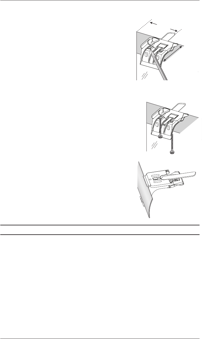
■Center the brackets on your marks and mark the location of the screw holes.
➤The minimum casement depth required for
installation brackets is 1".
➤The minimum casement depth required for a fully
recessed mount is 3
3
/
16
".
■Use a level to check that the mounting surface is level.
Shim the brackets, if necessary (use the top tab that was
removed from the brackets).
■Drill the screw holes using a
3
/
32
" drill bit.
CAUTION: Use drywall anchors when mounting into drywall.
■Attach the installation brackets using the screws provided.
IMPORTANT: Do not overtighten the screws. Check to
ensure the lever can be moved easily side to side. If not,
loosen the screws
in one-eighth turn increments until the
lever can be moved easily.
IMPORTANT: The front edges of the installation brackets
must be level and aligned to eachother.
■If using the optional back cover: Install the cover into
the back cover brackets. If necessary, trim the back cover
to the desired width.
Proceed to “Install the Shade” on page 8.
2" to 3"
Casement
Depth
Back
Cover
INSTALLATION
6
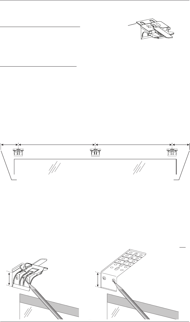
Mount the Installation Brackets — Outside Mount
Prepare the Installation Brackets
■Use pliers or heavy duty scissors to remove the top
tabs on the installation brackets.
NOTE: Save these tabs once removed. They may be used as shims, if necessary.
Mount the Installation Brackets
■Center the headrail over the window opening at the desired height. Use a pencil to lightly
mark each end of the headrail.
➤Alternatively, measure the width of the headrail and use that width to mark the headrail
end points over the window opening.
■Mark 2" to 3" from each end of theheadrail.
➤If more than two installation brackets came with your order, space additional bracket(s)
evenly between the two end brackets and mark their location. Mount into wood
whenever possible.
■Center the installation brackets or extension brackets on your marks and mark where to drill
the screw holes.
➤A minimum 1
1
/
8
" flat vertical surface isrequired for the installation brackets. Extension
brackets require 1
1
/
4
".
➤The tops of the installation brackets or extension brackets should be at the desired
height. The brackets should be level andaligned.
CAUTION: The rear of the brackets must be flush against a flat mounting surface. Do not
mount brackets oncurved molding.
Tab
Remove Top Tab
Back Cover Bracket
Window Opening
Space Evenly Space Evenly
2" to 3" 2" to 3"
Headrail End Mark Headrail End Mark
1
1
/
8
"Extension
Bracket
1
1
/
4
"
INSTALLATION
7
■Drill the screw holes using a
3
/
32
" drill bit.
CAUTION: Use drywall anchors when mounting into drywall.
■Attach the installation or extension
brackets using the screws provided.
IMPORTANT: The tops of the
installation brackets or extension
brackets must be level with their
front edges aligned.
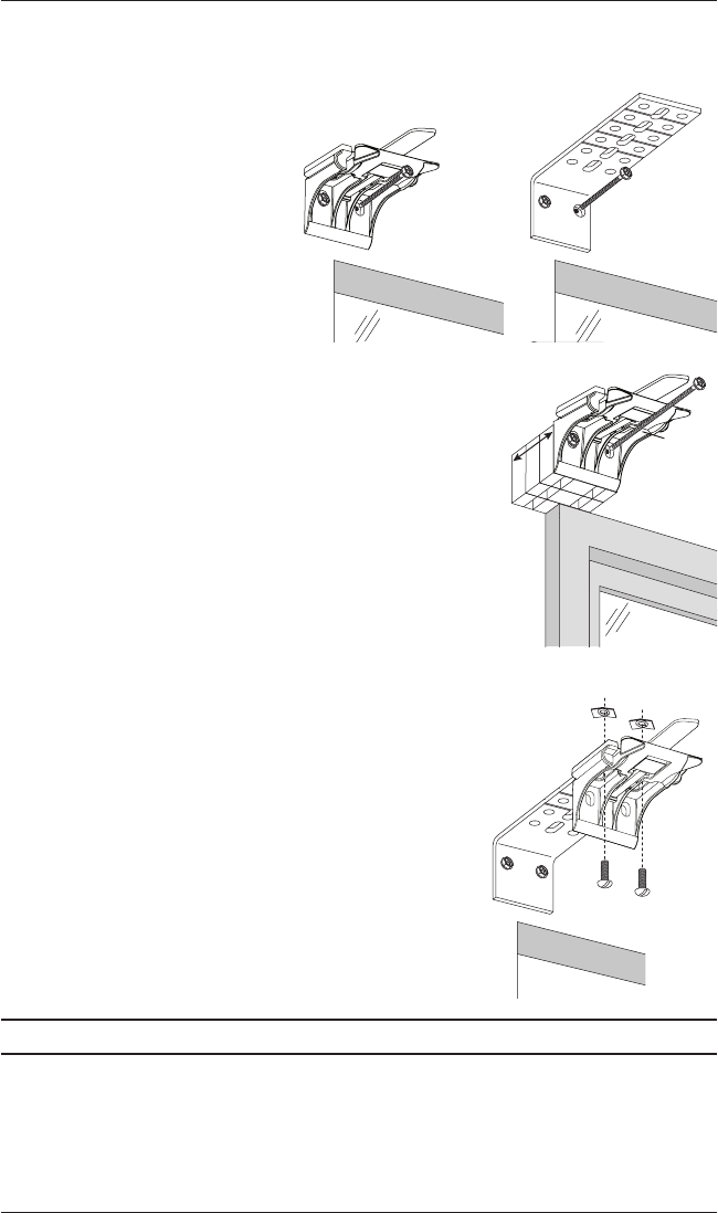
■If using spacer blocks, attach the spacer block(s) and
installation bracket to a flat vertical mounting surface
with #6screws long enough for asecure installation.
IMPORTANT: Do not add more than 1
1
/
2
" of
clearance using spacer blocks.
IMPORTANT: The tops of the installation brackets
must be level with the front edges aligned.
■If using extension brackets, attach an installation bracket
to the underside of each extension bracket using thespeed
nuts and screws provided.
Proceed to “Install the Shade” on page 8.
1
1
/
2
"
Maximum
Spacer
Blocks
Longer
Screw
Speed Nuts
Screws
INSTALLATION
8
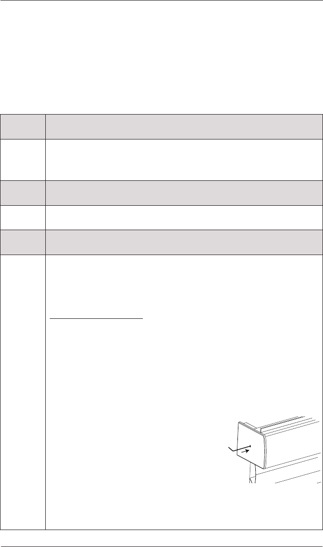
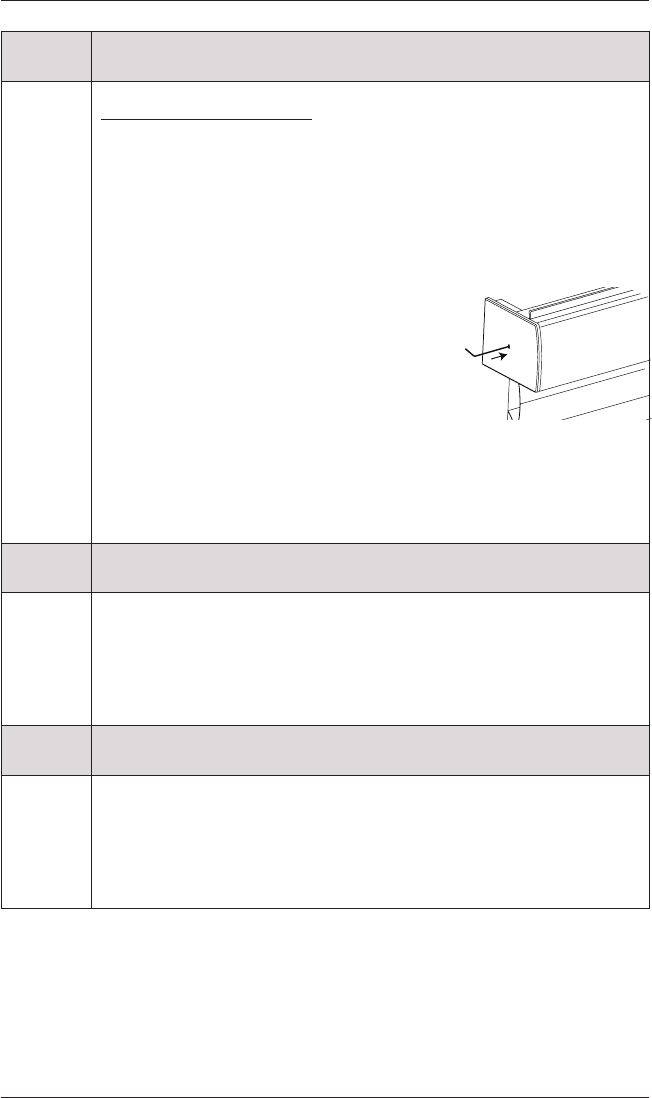
STEP 2 — Install the Shade
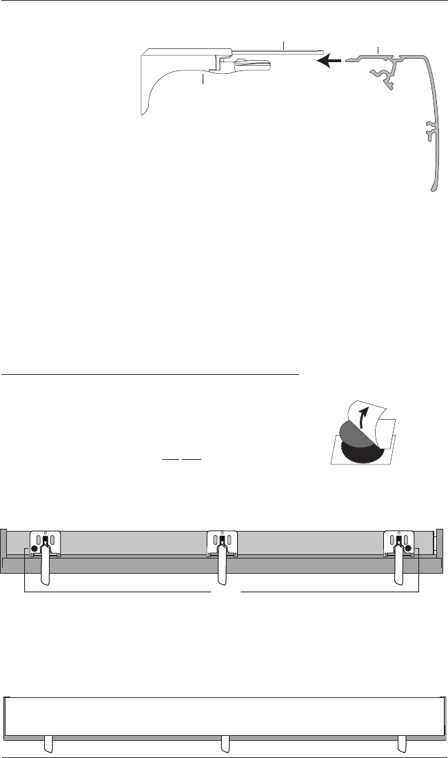
■Peel back the protective
covering from the top of
the headrail. Leave the
rest of the protective
covering on the front of
the headrail.
■Position the shade so
that the front faces you.
■Slide the headrail into
the installation brackets so the edge of the headrail is between the lever and the bracket,
asshown.
■Firmly push the headrail into each bracket until it clicks and the lever snaps to the right side
of the bracket.
IMPORTANT: Carefully pull on the headrail at each bracket to ensure it is
installedsecurely.
■Completely remove the protective covering from the headrail.
Attach the Dust Cover (Optional for Outside Mounts)
The dust cover is used to protect the top of the headrail from exposure on outside mounted
shades.
■Cut the dust cover to desired width.
■Remove the paper backing on one side of the hook and loop
fastener dots.
■Apply the dots to the installation brackets on each end of the shades.
■Remove the remaining paper backing from the dots.
■Center the dust cover over the top of the shade, above the dots.
■Press the dust cover down onto the dots.
Headrail
Installation
Bracket
Lever
Slide the Headrail
Between the Lever
and the Bracket.
Remove
Paper
Backing
Overhead View
No Dust Cover
Dots
Dust Cover Installed
INSTALLATION
9
STEP 3 — Connect the Power Source
NOTE: When power is connected to the motor, a green LED inside the manual control button
housing will flash to indicate the shade is ready for operation.
■Refer to the appropriate page based on your order.
➤For a battery wand, see below.
➤For a satellite battery pack, see page 10.
➤For an 18V DC power supply, see page12.
➤For an 18V DC power supply with daisy-chain connections, see page13.
➤For a C-size satellite battery wand or large DC power supply, see the instructions that
came with the unit.
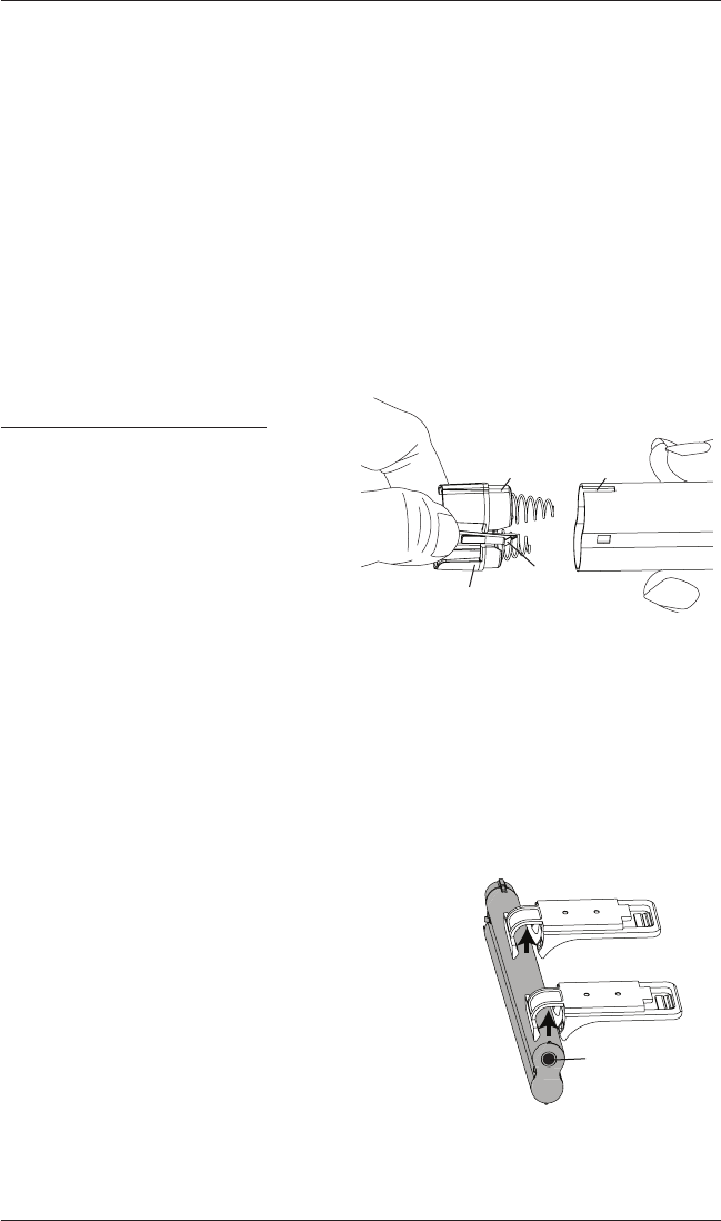
If You Have a Battery Wand...
Install the Batteries into the Battery Wand
■Squeeze the cap latch to release thecap.
■Remove the cap from the battery wand.
■Install the batteries according to the
instructions on the battery wand label.
➤Hunter Douglas recommends AA alkaline batteries for use with our battery-powered
shades. These will provide more than one year of operation, depending on usage.
Lithium and rechargeable batteries are not recommended.
■Replace the cap.
➤Align the tab with the end of the wand.
➤Press the cap on until it latches.
Mount the Battery Wand into theBattery Wand Clips
■Place the battery wand with its socket toward the motor
end of the shade.
■Push the battery wand straight up into the battery wand
clips until it snaps into place. Check to make sure the
battery wand is secure.
CAUTION: Be sure the cables do not become pinched
by the battery wand clips during installation. Damage or
overheating of components could result.
TabSlot
Cap
Latch
Battery
Wand
Squeeze
Place the socket
toward the motor end.
INSTALLATION
10
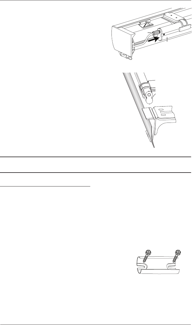
Plug the Power Cable into the Battery Wand
■From the back of the shade headrail, connect the
power cable (from the motor side) into the socket
on the battery wand.
■Two-On-One Headrail Shades. Plug in both
cables to the battery wands.
Install the Back Cover
■If using a back cover, install it into the back cover
brackets,
as shown.
Proceed to “Attach Magnetic Hold-Down Brackets (Optional)” on page14
or “Testing the Shade” on page15.
If You Have a Satellite Battery Pack...
Install the Batteries into the Battery Wand
■See the instructions on the previous page.
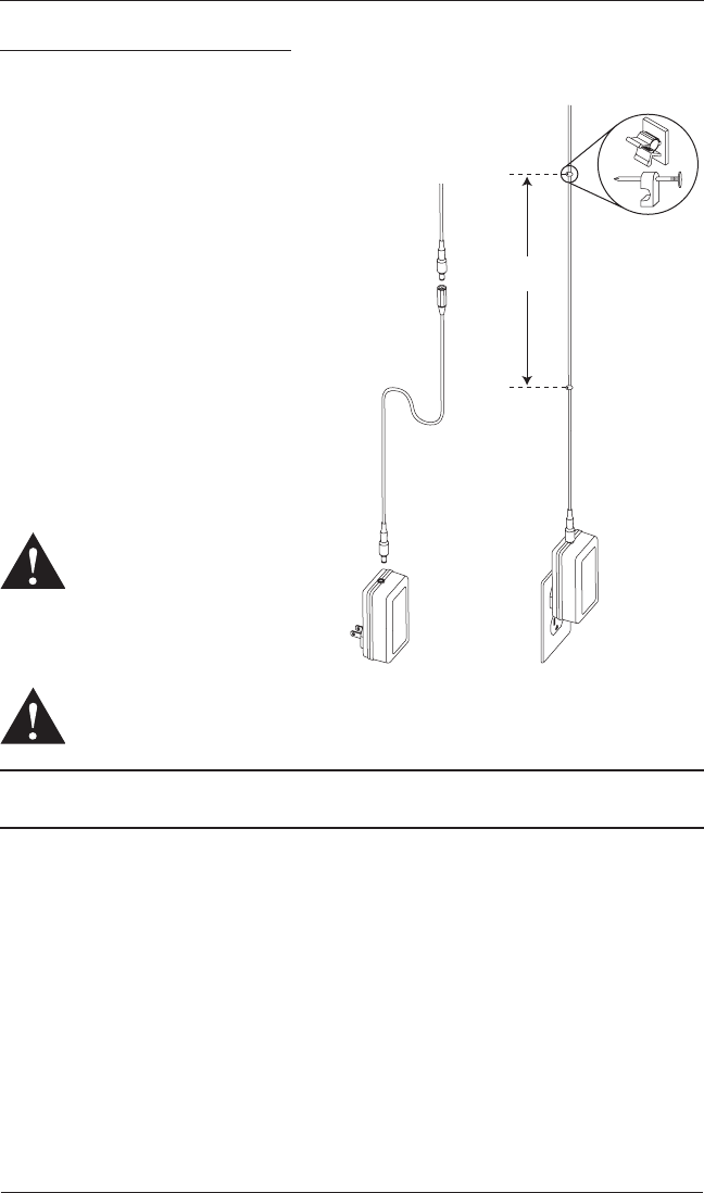
Mount the Satellite Battery Pack
■Decide where you want to mount the satellite battery pack. A satellite battery pack may be
mounted in any orientation.
■Mark the screw holes for the wall mount bracket.
■Drill the screw holes using a
3
/
32
" drill bit.
■Remove the backing from the double-sided tape. Press the
bracket into place.
■Attach the bracket using the screws provided.
Power
Cable
Battery
Wand
Back
Cover
Battery Wand
Wall Mount Bracket
INSTALLATION
11
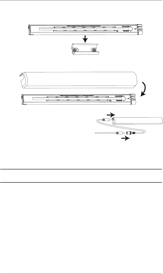
■Position the battery wand so the power cable is easily connected to the socket.
■Snap the battery wand into the wall mount bracket.
■Replace the cover with the slot aligned to the socket in the battery wand.
■Plug the power cable from the shade into
the extension cable.
■Plug the other end of the extension cable
into the socket in the battery wand.
■Two-On-One Headrail Shades. Plug in both
power cables into the extension cables and then
plug both extension cables into the sockets in the
battery wands.
Proceed to “Attach Magnetic Hold-Down Brackets (Optional)” on page14
or “Testing the Shade” on page15.
Socket
Battery Wand Cover
Slot
Socket
Battery Wand Cover
Extension
Cable
Power Cable
from Shading
INSTALLATION
12
If You Have a DC Power Supply...
Connect the Power Supply
■Plug the power cable from the shade into
the extension cable.
■Plug the other end of the extension cable
into the DC power supply.
■Plug the DC power supply into a standard
outlet.
■Secure the extension cable using wire
retainers (not supplied). If hiding the
cable behind the shade, make sure
it does not impede the operation of
theshade.
■Space the wire retainers approximately
15" apart along the power supply cable,
as shown.
WARNING: Keep cords and small
parts out of the reach of children.
They can wrap cords around their
necks and STRANGLE. They can
also put small parts in their
mouths and CHOKE.
WARNING: Electric shock and/or a fire hazard may occur, if not properly installed.
Proceed to “Attach Magnetic Hold-Down Brackets (Optional)” on page14
or “Testing the Shade” on page15.
Power Cable
from Shading
Extension
Cable
DC
Power
Supply
15"
Maximum
Wire Retainers
INSTALLATION
13
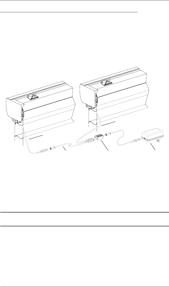
If You Have a DC Power Supply with Daisy-Chain Connections...
The daisy-chain feature allows up to three PowerView™ shades to be powered by a single DC
power supply. However, each shade can operate independently. The daisy-chain feature is only
available with the DC power supply option.
■Route the power cables from each shade to the connector, using an extension cable, if
necessary.
■Plug an extension cable into the connector and plug the cable into the DC power supply.
Two extension cables and two connectors are used for three shades.
■Plug the DC power supply into a standard outlet.
Two-On-One Headrail Shades
■Route the power cables from each side of the shade to the connector. Use extension cables,
if necessary.
■Plug the extension cables or power cables into the connector and plug the cable into the DC
power supply.
Proceed to “Attach Magnetic Hold-Down Brackets (Optional)” on page14
or “Testing the Shade” on page15.
Power Cable
from Shading
Power Cable
from Shading
Extension Cable Connector DC Power Supply
INSTALLATION
14
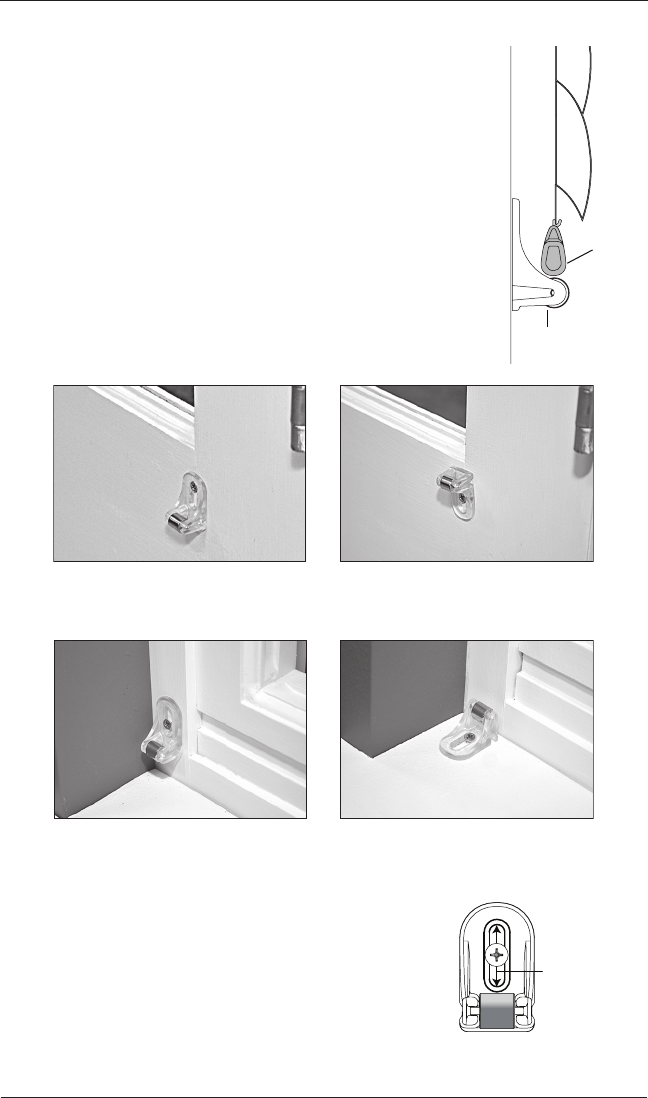
Attach the Magnetic Hold-Down Brackets (Optional)
■Lower the shade.
■Place the magnetic hold-down bracket onto the bottom rail just
inside the end cap, oriented as shown.
■Mark the screw location using the mounting options shown below.
➤The screw should be placed in the middle of the channel. This
will allow for adjustment.
■Drill the screw holes using a
3
/
32
" drill bit.
■Attach the hold-down brackets to the mounting surface using
the screws provided.
Hold-Down
Bracket
Bottom
Rail
Outside Mount
Preferred Alternate
Inside Mount
Preferred Alternate
Adjust bracket
height by
loosening the
screw and sliding
the bracket up or
down.
OPERATION
15
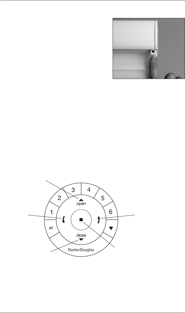
Testing the Shade
Use the manual control button to test the shade and
ensure that the motor and power source are working
correctly.
■Press the manual control button to lower the
shade. If the shade does not operate, see
“Troubleshooting” on page20.
■Test vane operation by pressing the manual control
button to open the vanes and then pressing it again
to close the vanes.
■After the vanes are fully closed, press the manual control button to raise the shade.
CAUTION: When raising the shade for the first time, observe how the fabric rolls up into
the headrail. It should roll up evenly. If the bottom rail is not level or the shade starts to rub
against either window jamb, immediately press the manual control button to stop the shade.
See “Adjust the Bottom Rail Weight” on page23.
■Two-On-One Headrail Shades have two motors and two battery packs. The right motor
operates the right shade and the left motor operates the left shade. Use the manual control
buttons on each side to test the two shades individually.
Using the PowerView™ Remote
First, activate the remote by pulling both plastic tabs from the back battery compartment.
IMPORTANT: If you have more than one remote, see “Adding Additional Remote(s) to the
PowerView™ Shade Network” in the PowerView Motorization Remote Control Guide.
Group 1
Group 2
OPEN
CLOSE
Group 3
Group 4
Group 5
Group 6
Favorite
(Shading/vane position)
LEFT
ARROW
T
ilts vanes closed
RIGHT ARROW
Tilts vanes open
STOP
(Press and hold for
programming mode)

OPERATION
16
Joining a Shade to a Group
IMPORTANT: The shade will not operate using the remote until it has been joined to a group.
1. Press and hold ■ STOP for 4 seconds to put the remote in program mode. The lights on the
remote will flash to indicate it is in program mode.
2. Press the desired group number (1 – 6) on the remote. The backlight for the group number
will flash to show it is selected.
3. Press and hold the manual control button on the shade.
4. While continuing to press the manual button, press ▲ OPEN on the remote. The shade will
move slightly to indicate it has joined the group. Release the manual control button.
5. Press and hold ■ STOP for 4 seconds to exit program mode. The lights will stop flashing.
Basic Operation
1. To wake up the remote, simply pick it up or press ■ STOP. The last group(s) selected will be
highlighted and active.
2. Press “all” or groups 1 – 6 to select specific shade(s) to move. Selected group button(s) will
light to show they are selected.
a. Multiple group buttons may be selected at a time.
b. To deselect a group, press the group button again. The backlight for that group button
will go out.
3. Press ▼ CLOSE to lower the selected shade(s).
4. Press the right arrow to open the vanes.
5. Press the left arrow to close the vanes.
6. Press ▲ OPEN to raise the selected shade(s).
7. Press ■ STOP to stop shade or vane movement anywhere along its travel.
8. While a shade is in motion, press the opposite of shade motion (▲ OPEN or ▼ CLOSE) to
reverse direction.
9. Press ♥ FAVORITE to send selected shade(s) to your preset “favorite” position. Refer to the
PowerView™ Motorization Remote Control Guide on how to set a favorite position.
Operating Tips
1. When the shade is raised, pressing the right arrow will first lower the shade and then open
the vanes.
2. When the shade is lowered with the vanes open, pressing ▲ OPEN will first close the vanes
and then raise the shade all the way.

OPERATION
17
Further Operation and Programming Information
PowerView™ Pebble™ Remote and/or PowerView Surface Remote Operation
For information regarding operation and programming of the PowerView remote, refer to your
PowerView Motorization Remote Control Guide.
PowerView Scene Controller
For information regarding operation and programming of the PowerView Scene Controller, refer
to your PowerView Motorization Scene Controller Guide.
PowerView App Operation
The PowerView Hub is required for PowerView App operation. For information regarding setup
and operation using the PowerView App, refer to the online PowerView App Software Guide at
hunterdouglas.com/powerview/support.
Resetting the Shade (If Necessary)
Basic Reset
The basic reset is used to reset the shade’s travel limits.
1. Press and hold the manual control button for 6 seconds. The shade will move slightly.
2. Release the manual control button. The shade will raise to its fully open position to set the
upper travel limit, then lower to the fully closed position with vanes open to set the lower
travel limit. The shade will move slightly one more time to indicate that the travel limits have
been reset.
Resetting Shade Programming
This reset erases all shade programming from memory, including group assignments, preventing
any input device from operating the shade. Its primary use is during installation to correct group
and network assignments. This reset does not affect travel limits.
1. Press and hold the manual control button for 12 seconds. The shade will move slightly after 6
seconds, then again after 12 seconds. Release the button.
2. Refer to “Joining a Shade to a Group” on page 18 to program the shade to a group.
OPERATION
18
Troubleshooting
If your shade is not operating correctly:
■First review the guide that came with your control device.
■Refer to the following troubleshooting procedures for specific solutions for your shade.
If questions remain, please contact the Hunter Douglas Customer Information Center at
1-888-501-8364.
Problem The shade will not snap into the installation brackets.
Solution Check that the installation brackets are aligned andlevel.
Check that the locking tab on the installation bracket slides over the headrail.
Problem The shade will not raise.
Solution If the hold-down brackets have been used, make sure they have been released.
Problem The shade does not roll up, or it rolls up too slowly.
Solution If the hold down brackets have been used, make sure they have been released.
Check that the shade is being raised straight up and is not skewing the fabric
against the headrail. If this is not the case, you can adjust by:
Adding Spring Tension
■Locate the adjustment behind the LEFT end cap cover.
➤The cover is removed by placing your thumb in the center and releasing
the snap on the top back corner.
■Raise the shade completely and hold into place.
■Push a
3
/
16
" Allen wrench into the access hole in the end cap of the shade
(about a
1
/
2
").
CAUTION: When pressing the
Allen wrench into the end, you are
compressing a spring and freeing the
lock from engagement.
To re-engage the lock, simply pull the Allen
wrench straight out of the end cap access hole.
➤Using
1
/
2
turn increments, rotate Allen wrench counter-clockwise to add
tension. Test and repeat, if necessary.
Push in
at Least
1
/
2
"
OPERATION
19
Problem The shade will drift up once stopped.
Solution Removing Spring Tension
■Locate the adjustment behind the LEFT end cap cover.
➤The cover is removed by placing your thumb in the center and releasing
the snap on the top back corner.
■Raise the shade completely and hold into place.
■Push a
3
/
16
" Allen wrench into the access hole in the end cap of the shade
(about a
1
/
2
").
CAUTION: When pressing the
Allen wrench into the end, you are
compressing a spring and freeing the
lock from engagement.
To re-engage the lock, simply pull the Allen
wrench straight out of the end cap access hole.
➤Using
1
/
2
turn increments, rotate Allen wrench counter-clockwise to add
tension. Test and repeat, if necessary.
Problem The shade is hard to raise or lower, or will not raise or lower.
Solution Shades cannot be forced into tight inside mount window openings. If an inside
mount, make sure there is clearance between the ends of the shade and the
window casement.
Check that the installation brackets are level. Shim to level, if necessary.
Problem Vanes do not align on side-by-side shades.
Solution Vane alignment is only guaranteed within
1
/
4
" when shades are ordered at
the same time, at the same height, with the same color and fabric, and when
specified on the order form.
Check that the windows are square and the sameheight.
Push in
at Least
1
/
2
"
OPERATION
20
Problem The shade raises or lowers unevenly, the bottom rail is not level when fully
raised, or the fabric winds unevenly or starts to rub against one end of the
headrail.
Solution Keep the bottom rail level while raising the shade. Side-to-side movement while
raising the shade may cause fabric to skew.
Check that the window is square by measuring the diagonals.
Check that the installation brackets are level. Shim to level, if necessary.
If the headrail is level and the window is square, adjust the bottom rail weight.
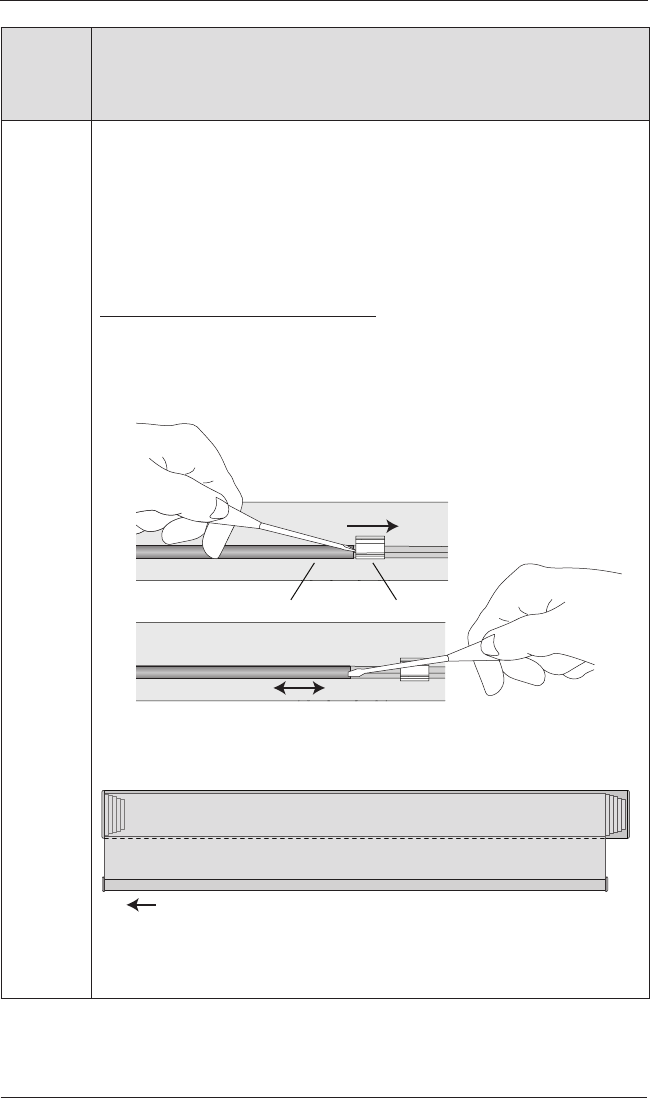
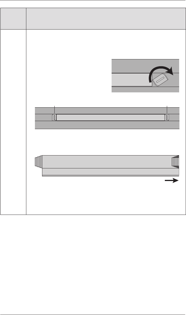
Adjusting the Bottom Rail Weight
IMPORTANT: Only adjust the bottom rail weight if the fabric does not roll up
straight into theheadrail.
First, release both weight locks. On the back of the bottom rail, insert a flat-
blade screwdriver into the slot in each weight lock and slide
them away from the weight.
Slide the weight, in 1" increments, in the direction the fabric is gathering.
Secure the weight by sliding each lock back in position next to the weight.
Test and, if necessary, adjust again.
Slide Lock to
Release Weight
Weight Weight Lock
Move Weight
Move Weight
Gathered
Fabric Fabric Roll in Headrail
Bottom Rail

OPERATION
21
Problem The shade will not fit into the installation brackets.
Solution If the shade has a battery wand, check that the wand is not interfering with the
installation brackets.
Check that the installation brackets are level and aligned. Adjust and/or shim to
level, if necessary.
Be sure the heads of the mounting screws are flush against the installation
bracket.
Check that the headrail is completely inserted into the installation brackets. See
“STEP 2 — Install the Shade” on page10.
Problem The shade does not operate using the manual control button.
Solution Unplug the power cable from the motor, then plug it back in. A green LED inside
the manual control button housing should flash to indicate the motor has power.
Check that the batteries in the battery wand, satellite battery pack, or C-size
satellite battery wand are correctly inserted and fresh.
Check that the battery wand, satellite battery pack, C-size satellite battery wand,
or DC power supply is securely connected to the power cable and the cables are
not pinched or caught in the headrail or installation brackets.
Problem The shade is not responding to the PowerView™ remote.
Solution IMPORTANT: A shade will not operate using the remote until it has been
joined to a group
Check that the correct group number is selected.
Check that the batteries in the remote are correctly inserted andarefresh. The
LEDs that backlight the remote should come on full bright when ■ STOP is
pressed.
Problem The vanes do not open when the shade is first operated.
Solution Make sure the shade is completely lowered.
Open and close the shade several times to help open the vanes. If necessary,
gently pull down on the bottom rail.
OPERATION
22
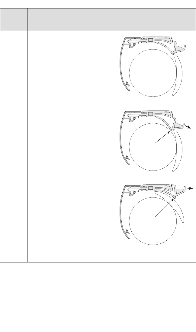
Problem The shade is hard to raise or lower, or the bottom rail does not stop at the
top limit.
Solution Check the adjustment position of
both limit stops. The top illustration
shows the correct adjustment. The
limit stop catches the bottom rail,
and the bottom of the limit stop is
slightly above or barely touching the
fabric roll.
In the second illustration, the limit
stop adjustment is too tight. The
fabric may not drop freely and could
even be damaged when the shade
is raised. To correct this, the limit
stop should be adjusted one step up.
Simply pull back on the rear of the
limit stop to adjust its position.
In the bottom illustration, the
adjustment is too loose. The bottom
rail can slip under the limit stop.
If the bottom rail rotates through
the headrail, it must be backed out
before adjusting the limit stop.
IMPORTANT: Both limit stops must
be adjusted to the same position or
else skewing may occur.
Pull Back
to Adjust
Fabric Roll
Bottom
Rail
Limit StopHeadrail
Pull Back
to Adjust
Too Tight —
Adjust One Step Up
Too Loose —
Adjust One Step Down

OPERATION
23
Problem The bottom rail does not raise or lower completely, or its location when fully
lowered has changed over time.
Solution The batteries may be low in the battery wand, satellite battery pack, or C-size
satellite battery wand. Replace the batteries.
Check that the battery wand, satellite battery pack, C-size satellite battery wand,
or DC power supply is securely connected to the power cable and the cables are
not pinched or caught in the headrail or installation brackets.
Check that there is clearance between the ends of the shade and the window
casement on inside mounts.
Check if the fabric rolls up evenly into the headrail. If not, see “Adjust the Bottom
Rail Weight” on page23.
Reset the travel limits. See “Resetting the Shade” on page19.
See the PowerView™ Motorization Remote Control Guide for operation or
programming troubleshooting solutions.
Problem Adjacent shades do not roll up evenly.
Solution It is considered normal if the roll-up on both shades is within
5
/
16
" of each other.
If one shade rolls up tighter than another, lower and raise both shades several
times.
Reset the shade. See “Resetting the Shade” on page19.
Check that the shade fabric is not catching on any brackets or components.
Check that the fabric winds evenly and does not rub against the headrail. If
uneven, see “Adjust the Bottom Rail Weight” on page23.
Problem Two-On-One Headrail Shades Only: The center gap is not even from the top
to the bottom of the shade, interfering with the function of the shade.
Solution Ensure the entire length of the headrail is straight and level. If the center portion
of the headrail is higher than the ends, the center gap will close together. If the
center portion of the headrail is lower than the ends, the center gap increases. If
necessary, adjust the height of each bracket by moving it within the screw slots
or by using shims.
OPERATION
24
Problem The shade raises or lowers unevenly, the fabric rubs against one end of the
headrail, or the bottom rail is uneven when fullyraised.
Solution Check that the window is square by measuring the diagonals.
Check that the installation brackets are level. Shim to level, ifnecessary.
Adjust the Bottom Rail Weight:
■Release the weight clips by inserting
a flat blade screwdriver into the
weight clip and turning clockwise.
■Move the weight in 1" increments toward the side where the fabric
isgathering.
■Secure the weight clips in position by turning them counterclockwise after
making the adjustment.
■Test and, if necessary, adjust again.
Weight
Bottom Rail
Weight
Clip
Weight
Clip
Fabric Roll
Gathered
Fabric
Move Weight

OPERATION
25
Problem The vanes do not close fully when the shade stops in the lowest position.
Solution The shade should be programmed to stop in its lowest position with the vanes
closed. A small distance between the front and back fabric facings in the fully
closed position is normal.
■If this distance is excessive or moves over time, open the shade to its full
“vane open” position and try again. If this does not correct the problem,
reset the bottom limit. See “Resetting the Shade” on page19.
■See the PowerView™ Motorization Remote Control Guide for operation or
programming troubleshooting solutions.
Problem The shade raises from the sill when the vanes areclosed.
Solution A small gap between the sill and the bottom of the shade is normal in the fully
lowered “vane closed” position. The gap is necessary to allow for the unimpeded
movement of the bottomrail.
■If this distance is excessive or moves over time, open the shade to its full
“vane open” position and try again. If this does not correct the problem,
reset the bottom limit. See “Resetting the Shade” on page19.
■See the PowerView Motorization Remote Control Guide for operation or
programming troubleshooting solutions.
Problem The front fabric appears to cling to the back fabric.
Solution Lightly apply a static spray for home furnishings. Follow the manufacturer’s
directions. Allow the shade to dry in the fully lowered position. If necessary,
reapply the static spray each time the shade is professionally cleaned.
CARE
26
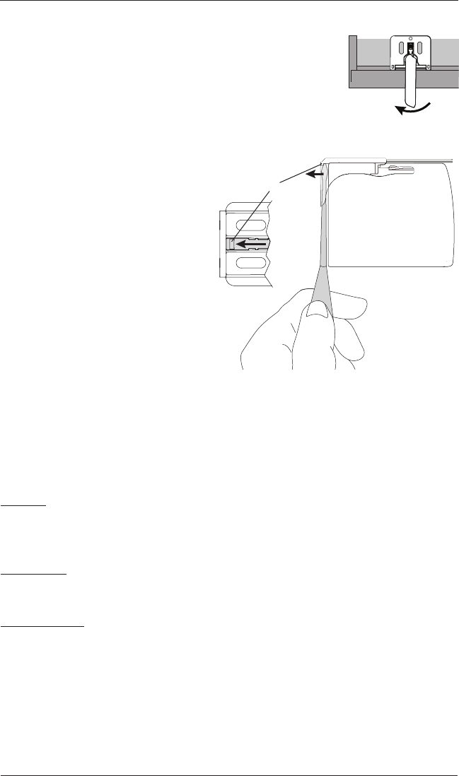
Removing the Shade
■Move each lever of the installation brackets to the left to release
the shade.
➤A flat blade screwdriver can be used to move the lever.
CAUTION: Be very careful not to tear or damage thefabric.
➤If the lever is inaccessible or
inoperable, lower the shade until
you can see the underside of the
bracket. Carefully reach a small
flat blade screwdriver behind the
shade to the tab on bottom of the
bracket between the screw holes.
➤Push the tab away from the shade
and pull the headrail to release it
from the bracket.
■Carefully pull the shade to remove it
from the brackets.
Cleaning Procedures
Sonnette™ Cellular Shades are made from anti-static, dust-resistant materials which repel dirt
and dust. The following options are available if your shade needs cleaning.
CAUTION: Do not steam the shades.
Dusting
■Regular light dusting with a feather duster is all the cleaning that needed in most
circumstances.
Vacuuming
■Use a hand-held vacuum with low suction for more thorough dust removal.
Spot-Cleaning
CAUTION: Do not use spot clean treatment on Highline™, Textura™ and Elan™ Metallic fabrics.
■Prepare a solution of warm water and a mild detergent.
■Dampen a clean cloth in the solution and wring it out.
■Dab the spot with the dampened cloth until it is gone. Do not rub the fabric.
■Allow the shade to dry in the completely lowered position.
Move Lever to Left
Top View
Installation Bracket
End Cap
Tab
Underside of
Bracket

DECLARATIONS
27
27
U.S. Radio Frequency FCC Compliance
FCC ID information is located behind the motor-side end cap. The end cap may be removed to view this
information.
This device complies with Part 15 of the FCC Rules. Operation is subject to the following two conditions:
(1) This device may not cause harmful interference, and
(2) This device must accept any interference received, including interference that may cause undesired
operation.
This equipment has been tested and found to comply with the limits for a Class B digital device, pursuant
to Part 15 of the FCC Rules. These limits are designed to provide reasonable protection against harmful
interference in a residential installation. This equipment generates, uses and can radiate radio frequency
energy and, if not installed and used in accordance with the instructions, may cause harmful interference
to radio communications. However, there is no guarantee that interference will not occur in a particular
installation. If this equipment does cause harmful interference to radio or television reception, which can be
determined by turning the equipment off and on, the user is encouraged to try to correct the interference by
one or more of the following measures:
• Reorient or relocate the receiving antenna.
• Increase the separation between the equipment and receiver.
• Connect the equipment into an outlet on a circuit different from that to which the receiver is connected.
• Consult the dealer or an experienced radio/TV technician for help.
Any changes or modifications not expressly approved by the party responsible for compliance could void the
user’s authority to operate the equipment.
Industry Canada
Under Industry Canada regulations, this radio transmitter may only operate using an antenna of a type
and maximum (or lesser) gain approved for the transmitter by Industry Canada. To reduce potential
radio interference to other users, the antenna type and its gain should be so chosen that the equivalent
isotropically radiated power (e.i.r.p.) is not more than that necessary for successful communication.
This device complies with Industry Canada licence-exempt RSS standard(s). Operation is subject to the
following two conditions: (1) this device may not cause interference, and (2) this device must accept any
interference, including interference that may cause undesired operation of the device.
Class B Digital Device Notice
This Class B digital apparatus complies with Canadian ICES-003, RSS-Gen and RSS-210.
CAN ICES-3 (B)/NMB-3(B)
European Conformity
We, the undersigned,
Hunter Douglas Window Fashions
One Duette Way, Broomfield, CO 80020, USA
Hunter Douglas Europe B.V.
Piekstraat 2, 3071 EL Rotterdam, The Netherlands
certify and declare under our sole responsibility that assembly PV4 conforms with the essential
requirements of the EMC directive 2004/108/EC and R&TTE directive 1999/5/EC.
A copy of the original declaration of conformity may be found at:
www.hunterdouglas.com/RFcertifications.

Notes

The Hunter Douglas® Lifetime Guarantee is an expression of our desire to provide a thoroughly satisfying
experience when selecting, purchasing and living with your window fashion products. If you are not thoroughly
satisfied, simply contact Hunter Douglas at (888) 501-8364 or visit hunterdouglas.com. In support of this policy
of consumer satisfaction, we offer our Lifetime Limited Warranty as described below.
NOTE: In no event shall Hunter Douglas or its licensed fabricators/distributors be liable or responsible for incidental
or consequential damages or for any other indirect damage, loss, cost or expense. Some states do not allow the exclusion or
limitation of incidental or consequential damages, so the above exclusion or limitation may not apply to you. This warranty
gives you specific legal rights, and you may also have other rights which vary from state to state.
Different warranty periods and terms apply for commercial products and applications.
Hunter Douglas (or its licensed fabricator/distributor) will repair or replace the
window fashion product or components found to be defective.
COVERED
BY A LIFETIME LIMITED WARRANTY
• Hunter Douglas window fashion products are
covered for defects in materials, workmanship
or failure to operate for as long as the original
retail purchaser owns the product (unless shorter
periods are provided below).
• All internal mechanisms.
• Components and brackets.
• Fabric delamination.
• Operational cords for a full 7 years from the
date of purchase.
• Repairs and/or replacements will be made with
like or similar parts or products.
• Hunter Douglas motorization components are
covered for 5 years from the date of purchase.
NOT COVERED
BY A LIFETIME LIMITED WARRANTY
• Any conditions caused by normal wear and tear.
• Abuse, accidents, misuse or alterations to the
product.
• Exposure to the elements (sun damage, wind,
water/moisture) and discoloration or fading
over time.
• Failure to follow our instructions with respect
to measurement, proper installation, cleaning
or maintenance.
• Shipping charges, cost of removal and reinstallation.
TO OBTA IN WARRANTY SERVICE
1. Contact your original dealer (place of purchase) for warranty assistance.
2. Visit hunterdouglas.com for additional warranty information, frequently asked questions and access to service locations.
3. Contact Hunter Douglas at (888) 501-8364 for technical support, certain parts free of charge, for assistance in obtaining
warranty service or for further explanation of our warranty.
XXXXXXXXX 9/16